Embed Size (px)
Citation preview
Über die blauen Reiter am rechten Rand können Sie direkt zu den Kapiteln springen. Mit den oberen Schaltflächen wechseln Sie zwischen Standard und Vollbild oder drucken die aktuelle Seite aus. Auf der jeweiligen Startseite sind die Hauptpunkte mit den entsprechenden Abschnitten verknüpft. Mit den unteren Schaltflächen können Sie hin und her blättern.Sie benötigen das Programm Adobe Reader möglichst in der aktuellsten Version, mindestens aber Version 6. Sie können sich den kostenlosen Adobe Reader unter folgendem Link herunterladen: www.adobe.com/de
Use the blue tabs at the right margin to go directly to the respective chapters.The buttons above enable switching between standard and full-screen formats and printing of the page.On each cover page the main items are linked to the corresponding chapter.The lower buttons allow scrolling up and down.Adobe Reader is required, at least version 6 but preferably the most recent version. Adobe Reader can be downloaded free of charge at: www.adobe.com/de
WWW.ANKER-SCHROEDER.DE © 09
Hinweis für die Benutzung
Direction for Use
Wege zum Ziel:
Guide to your solution:
2 WWW.ANKER-SCHROEDER.DE © 09 3WWW.ANKER-SCHROEDER.DE © 09
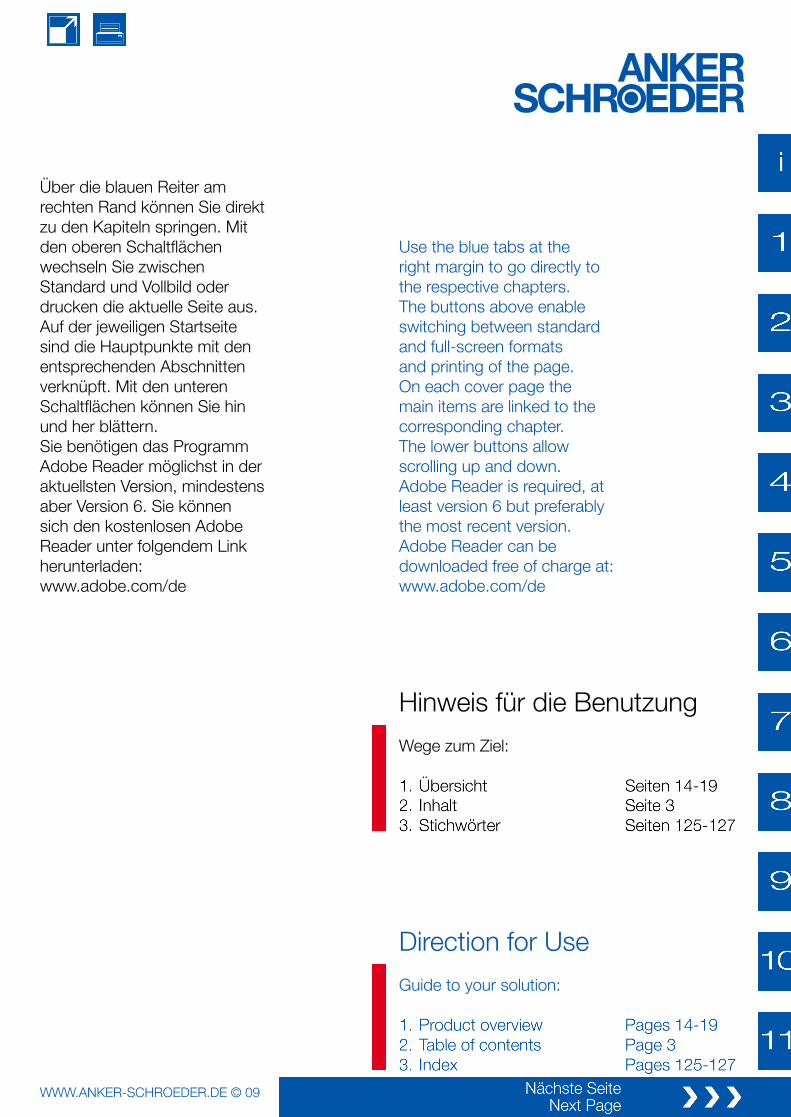
Leysiel /Gebr. Neumann,Emden
Einleitung, GeschichteÜbersichten
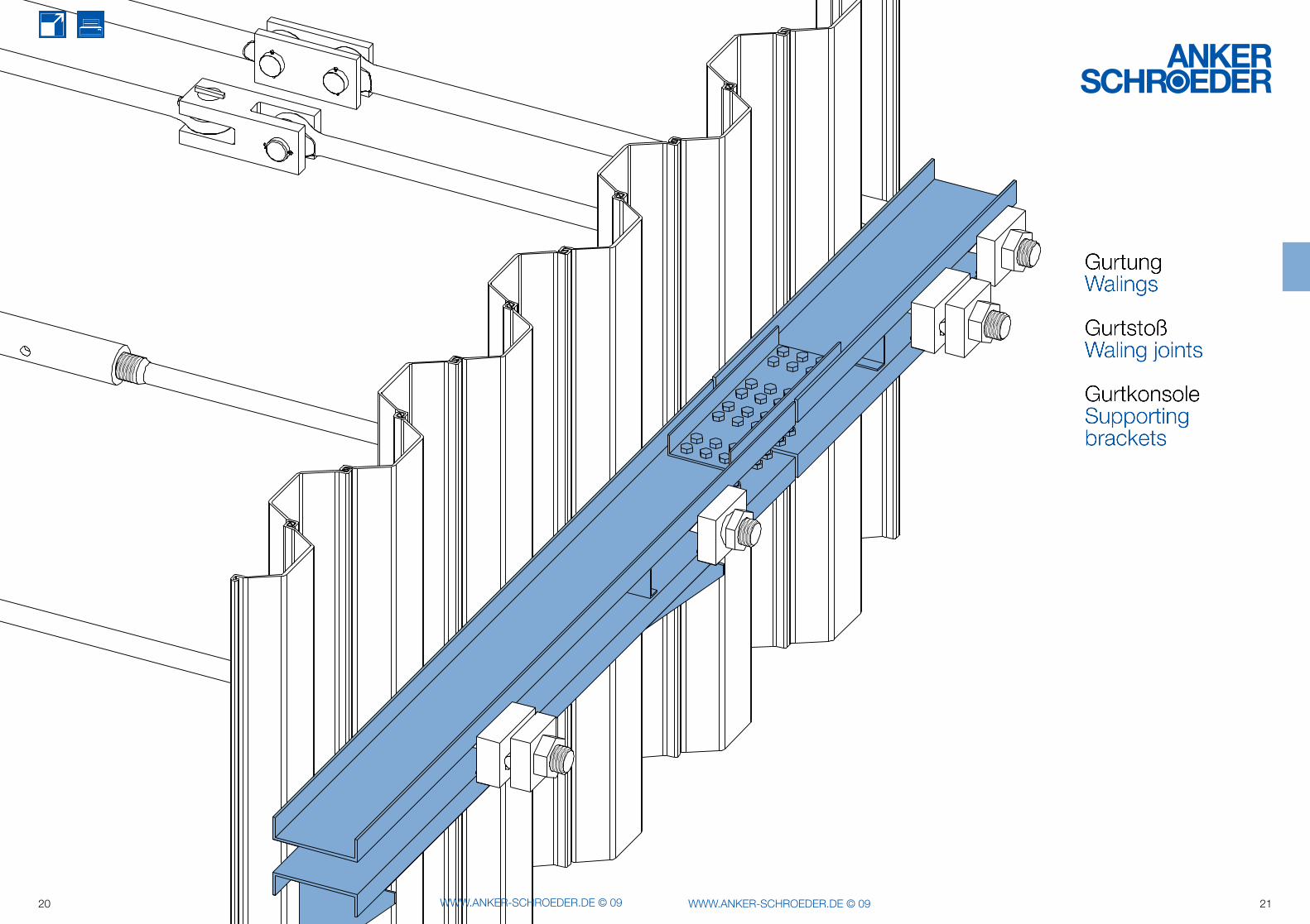
GurtungGurtstoßGurtkonsole
GurtbolzenVordere / Hintere Platte für Gurtbolzen
AnkerRV-Pfahl / BohrpfahlReibepfahlanschluss
Spannschloss, MuffeGelenkige Verbindung
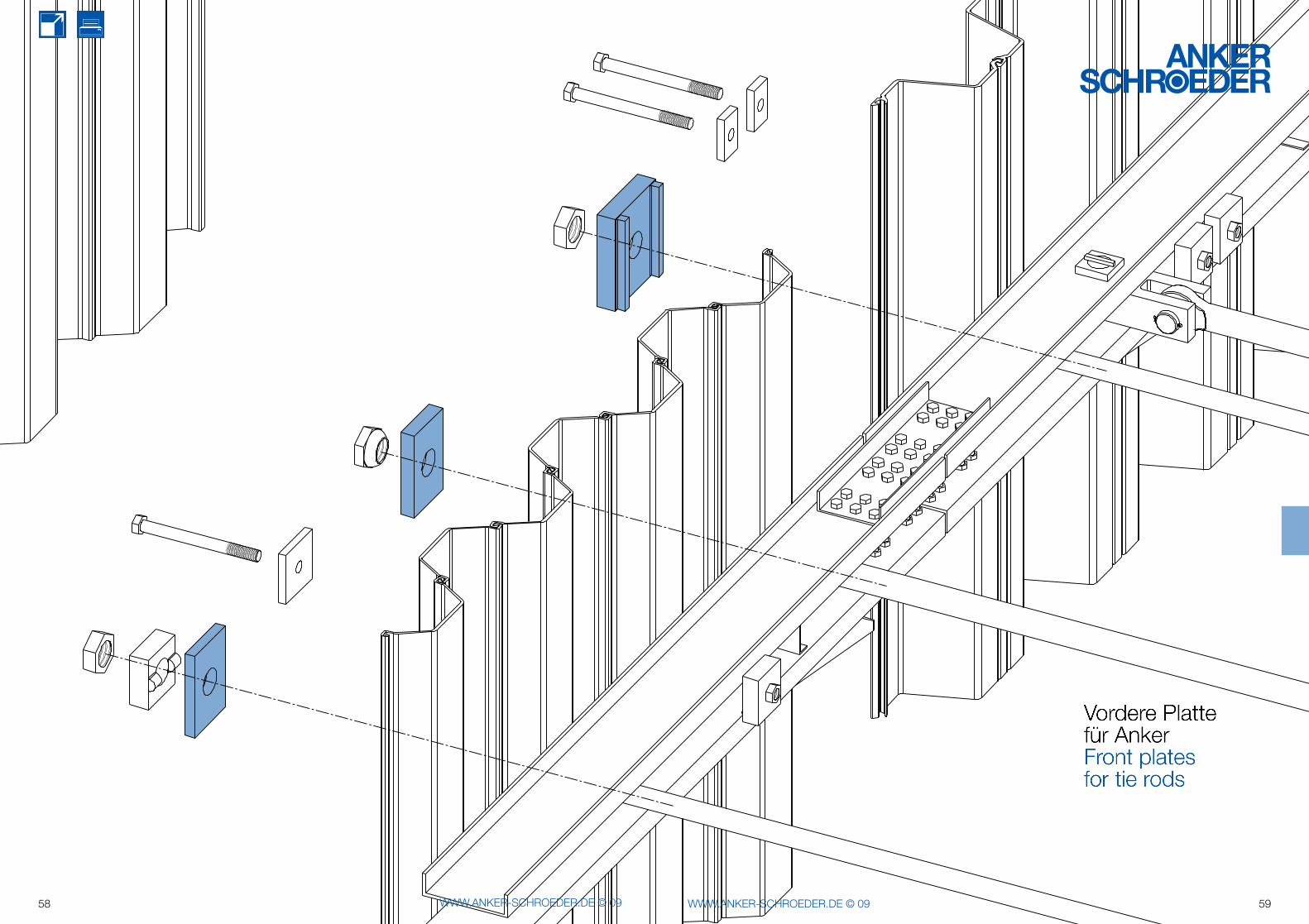
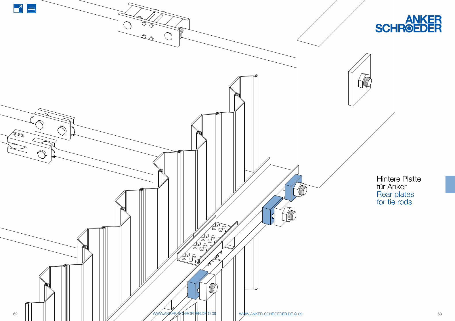
Vordere Platte für AnkerHintere Platte für Anker
Neigung und SchräglageGelenkscheibe, Wälzmutter
Anschluss für schwere WändeAnschluss für BetonwändePlatte für Betonauflage
HolmprofilNische, Leiter, Haltebügel
Poller, Pollerbefestigung
Anhang:Anfrageschema, AusschreibungstextStichwortverzeichnis
Introduction, company historyGeneral information
WalingsWaling jointsSupporting brackets
Waling boltsFront / rear plates for waling bolts
Tie rodsDisplacement-injected piles/drill foundation pilesConnections for friction-fitted piles
Turnbuckles, coupling sleevesHinged connections
Front plates for tie rodsRear plates for tie rods
Declination and inclinationRocker plates, swivel nuts
Connections for high-modulus wallsConnections for concrete wallsPlates for installation on concrete
Capping profilesRecesses, ladders, handrails
Bollards, bollards anchoring
Appendix:Quotation checklist, assistance for tendersIndex
Inhalt Contents
4 WWW.ANKER-SCHROEDER.DE © 09 5WWW.ANKER-SCHROEDER.DE © 09
Leysiel / Gebr. Neumann, Emden
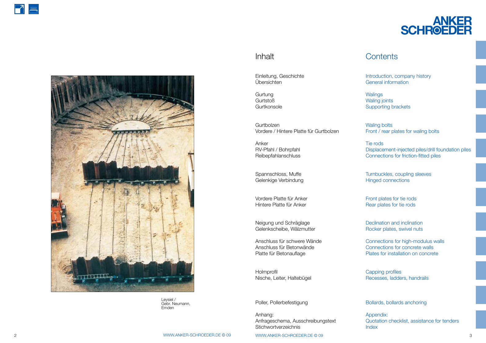
Spundwand mit Ausrüstungsmaterial
Distribution plate for anchorage
Upset round steel tie rods provide a proven safe and economic anchoring solution.
Sheet piling with accessories
Verteilungsplatte für Verankerung
Aufgestauchte Rundstahlankerhaben sich als sichere undwirtschaftliche Verankerung bewährt.
ist das Motto, unter dem ANKER-SCHROEDER seit Jahrzehnten zuverlässig Zugelemente - hauptsächlich aus Rundstahl - fertigt.Mit diesem Handbuch wollen wir allen Planern, Konstrukteuren, Bauleitern und Einkäufern eine Hilfestellung bei der Auswahl von Bauteilen für den Stahlwasserbau geben, aber auch Anregungen für Gespräche mit uns.Mit dem Erscheinen dieses Handbuches verlieren ältere Informationsunterlagen ihre Gültigkeit.
Für Verbesserungsvorschläge und Hinweise für die nächste Auflage sind wir Ihnen dankbar. Sprechen Sie uns bitte an!
Gerne unterstützen wir Sie im Auftragsfall mit Berechnungen und Zeichnungen, die wir zumeist kostenlos erstellen.
Auf Wunsch bieten wir Montage, Spannarbeiten oder die Vermietung von Vorrichtungen an.
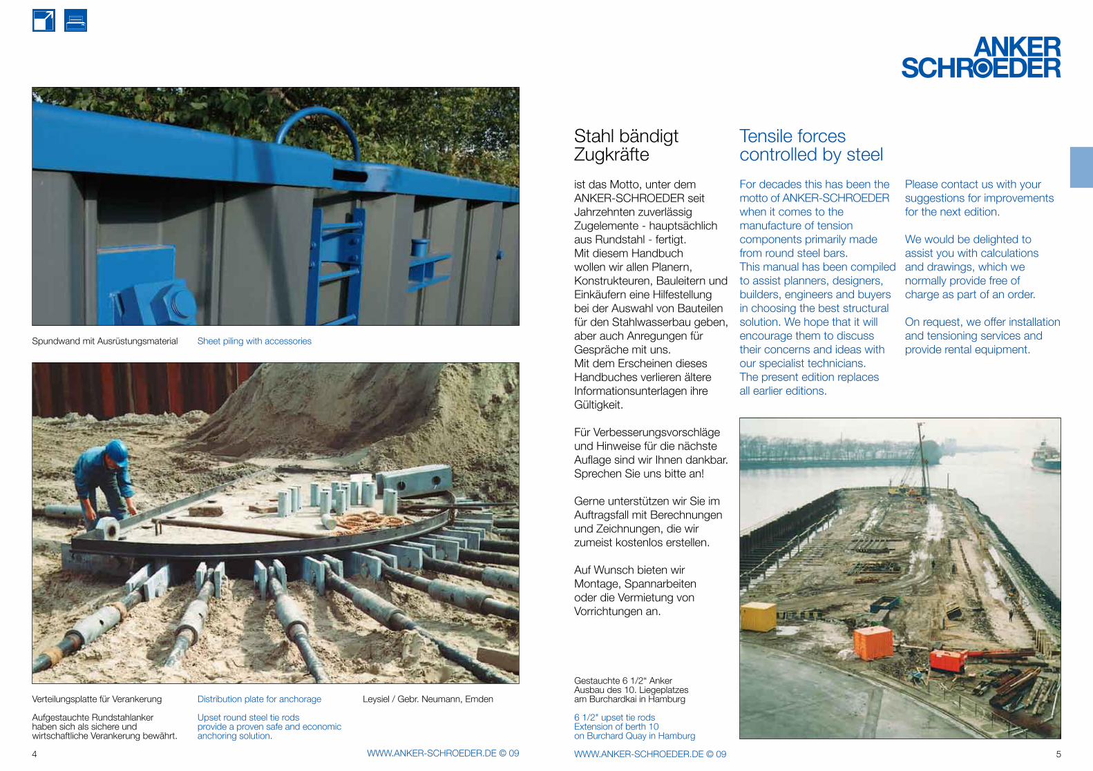
Gestauchte 6 1/2“ AnkerAusbau des 10. Liegeplatzesam Burchardkai in Hamburg
6 1/2" upset tie rodsExtension of berth 10on Burchard Quay in Hamburg
For decades this has been the motto of ANKER-SCHROEDER when it comes to the manufacture of tension components primarily made from round steel bars. This manual has been compiled to assist planners, designers, builders, engineers and buyers in choosing the best structural solution. We hope that it will encourage them to discuss their concerns and ideas with our specialist technicians.The present edition replaces all earlier editions.
Stahl bändigtZugkräfte
Tensile forces controlled by steel
Please contact us with your suggestions for improvements for the next edition.
We would be delighted to assist you with calculations and drawings, which we normally provide free of charge as part of an order.
On request, we offer installation and tensioning services and provide rental equipment.
6 WWW.ANKER-SCHROEDER.DE © 09 7WWW.ANKER-SCHROEDER.DE © 09
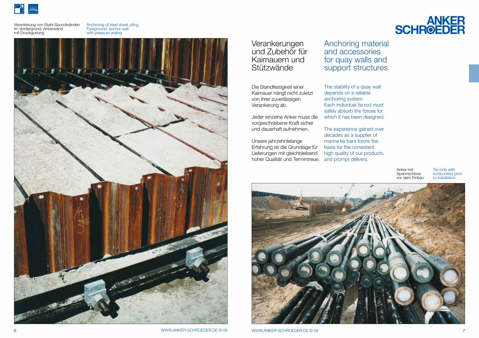
Verankerung von Stahl-SpundwändenIm Vordergrund: Ankerwandmit Druckgurtung
Anchoring of steel sheet pilingForeground: anchor wall with pressure waling
Die Standfestigkeit einer Kaimauer hängt nicht zuletzt von ihrer zuverlässigen Verankerung ab.
Jeder einzelne Anker muss die vorgeschriebene Kraft sicher und dauerhaft aufnehmen.
Unsere jahrzehntelange Erfahrung ist die Grundlage für Lieferungen mit gleichbleibend hoher Qualität und Termintreue.
The stability of a quay wall depends on a reliable anchoring system.Each individual tie rod must safely absorb the forces for which it has been designed.
The experience gained over decades as a supplier of marine tie bars forms the basis for the consistent high quality of our products and prompt delivery.
Anker mitSpannschlossvor dem Einbau
Tie rods with turnbuckles prior to installation
Verankerungenund Zubehör fürKaimauern undStützwände
Anchoring material and accessories for quay walls and support structures
8 WWW.ANKER-SCHROEDER.DE © 09 9WWW.ANKER-SCHROEDER.DE © 09
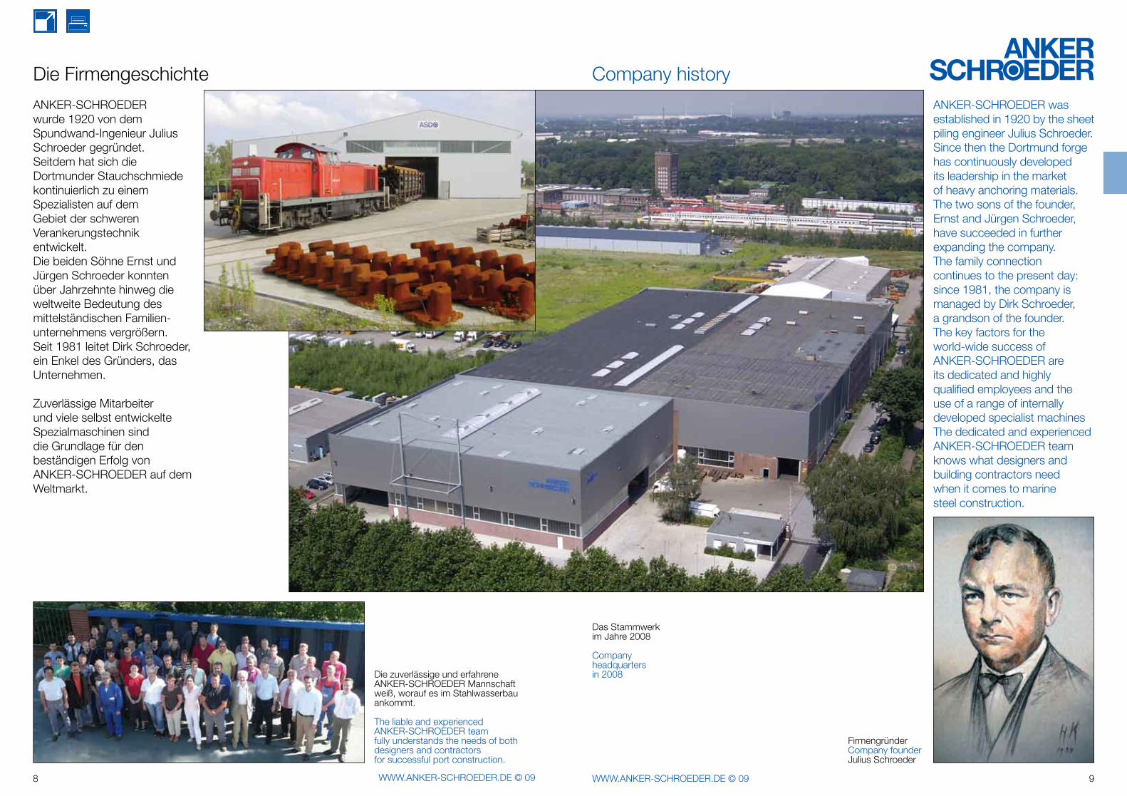
ANKER-SCHROEDER wurde 1920 von dem Spundwand-Ingenieur Julius Schroeder gegründet. Seitdem hat sich die Dortmunder Stauchschmiede kontinuierlich zu einem Spezialisten auf dem Gebiet der schweren Verankerungstechnik entwickelt. Die beiden Söhne Ernst und Jürgen Schroeder konnten über Jahrzehnte hinweg die weltweite Bedeutung des mittelständischen Familien-unternehmens vergrößern.Seit 1981 leitet Dirk Schroeder, ein Enkel des Gründers, das Unternehmen.
Zuverlässige Mitarbeiter und viele selbst entwickelte Spezialmaschinen sind die Grundlage für den beständigen Erfolg von ANKER-SCHROEDER auf dem Weltmarkt.
The liable and experienced ANKER-SCHROEDER team fully understands the needs of both designers and contractors for successful port construction.
Die zuverlässige und erfahreneANKER-SCHROEDER Mannschaft weiß, worauf es im Stahlwasserbau ankommt.
Die Firmengeschichte
ANKER-SCHROEDER was established in 1920 by the sheet piling engineer Julius Schroeder. Since then the Dortmund forge has continuously developed its leadership in the market of heavy anchoring materials. The two sons of the founder, Ernst and Jürgen Schroeder, have succeeded in further expanding the company.The family connection continues to the present day: since 1981, the company is managed by Dirk Schroeder, a grandson of the founder.The key factors for the world-wide success of ANKER-SCHROEDER are its dedicated and highly qualified employees and the use of a range of internally developed specialist machines The dedicated and experienced ANKER-SCHROEDER team knows what designers and building contractors need when it comes to marine steel construction.
FirmengründerCompany founderJulius Schroeder
Das Stammwerk im Jahre 2008
Company headquartersin 2008
Company history
10 WWW.ANKER-SCHROEDER.DE © 09 11WWW.ANKER-SCHROEDER.DE © 09
Sie können unseren Produkten vertrauen! You can rely on our products!
We only usestandardised and certified materials.
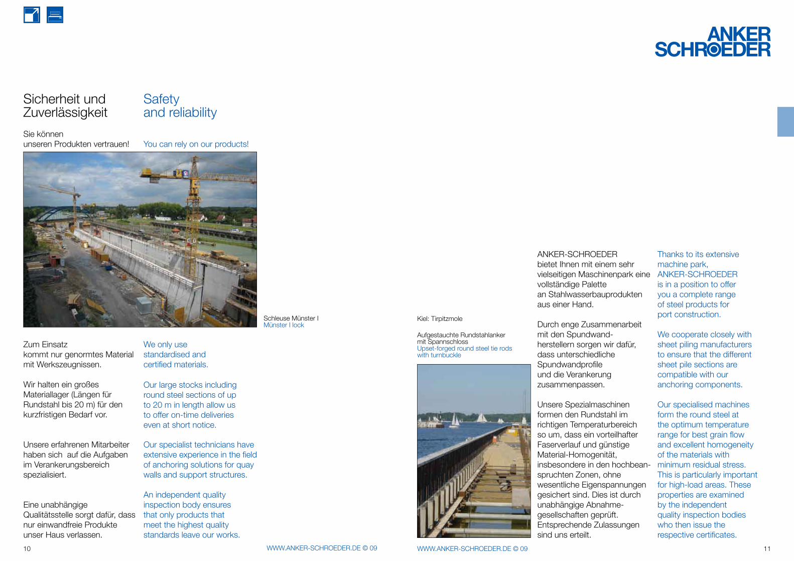
Schleuse Münster IMünster I lock
Eine unabhängige Qualitätsstelle sorgt dafür, dass nur einwandfreie Produkte unser Haus verlassen.
Unsere erfahrenen Mitarbeiter haben sich auf die Aufgaben im Verankerungsbereich spezialisiert.
Wir halten ein großes Materiallager (Längen für Rundstahl bis 20 m) für den kurzfristigen Bedarf vor.
Zum Einsatz kommt nur genormtes Material mit Werkszeugnissen.
Our large stocks including round steel sections of up to 20 m in length allow us to offer on-time deliveries even at short notice.
Our specialist technicians have extensive experience in the field of anchoring solutions for quay walls and support structures.
An independent quality inspection body ensures that only products that meet the highest quality standards leave our works.
Sicherheit und Zuverlässigkeit
Safety and reliability
ANKER-SCHROEDER bietet Ihnen mit einem sehr vielseitigen Maschinenpark eine vollständige Palette an Stahlwasserbauprodukten aus einer Hand.
Durch enge Zusammenarbeit mit den Spundwand-herstellern sorgen wir dafür, dass unterschiedliche Spundwandprofile und die Verankerung zusammenpassen.
Unsere Spezialmaschinen formen den Rundstahl im richtigen Temperaturbereich so um, dass ein vorteilhafter Faserverlauf und günstige Material-Homogenität, insbesondere in den hochbean-spruchten Zonen, ohne wesentliche Eigenspannungen gesichert sind. Dies ist durch unabhängige Abnahme-gesellschaften geprüft. Entsprechende Zulassungen sind uns erteilt.
Kiel: Tirpitzmole
Aufgestauchte Rundstahlanker mit SpannschlossUpset-forged round steel tie rodswith turnbuckle
Thanks to its extensive machine park,ANKER-SCHROEDER is in a position to offer you a complete range of steel products for port construction.
We cooperate closely with sheet piling manufacturers to ensure that the different sheet pile sections are compatible with our anchoring components.
Our specialised machines form the round steel at the optimum temperature range for best grain flow and excellent homogeneity of the materials with minimum residual stress. This is particularly important for high-load areas. These properties are examined by the independent quality inspection bodies who then issue the respective certificates.
12 WWW.ANKER-SCHROEDER.DE © 09 13WWW.ANKER-SCHROEDER.DE © 09
Qualität heißt, den Anforderungen der Kunden zu entsprechen.Diese Definition des Begriffes Qualität ist ein Ziel der Unternehmenspolitik von ANKER-SCHROEDER.
Darüber hinaus helfen wir unseren Kunden in allen Bereichen von der technischen Beratung über die fachgerechte Produktion bis hin zur Einhaltung der gewünschten Liefertermine.
Qualität wird bei ANKER-SCHROEDER durch fortlaufende Aus- und Weiterbildung der Mitarbeiter gewährleistet und durch eine unabhängige Qualitätsstelle unterstützt. Dies ist durch die Zulassungen der Abnahmegesellschaften dokumentiert (ABS, BV, DNV, GL, LRS, TÜV). Der große Eignungsnachweis zum Schweißen nach DIN 18800-7 und DIN 19704 ist vorhanden.
Durch ständige Weiter-entwicklung, wie z.B. die Einführung von Qualitätszirkeln und die Integration eines Qualitätssicherungssystems nach DIN EN ISO 9001:2000 stellen wir uns den steigenden Anforderungen der Zukunft zum Vorteil unserer Kunden.
Quality means meeting the requirements of the customer.
This definition of quality is at the heart of the corporate policy of ANKER-SCHROEDER.
In addition to providing quality products, we assist our customers in all their activities with initial advice and the provision of suitable components as well as on-time delivery.
Quality is ensured by continuous training of the staff and supported by an independent quality inspection body. The certificates of approval by recognised organisations (ABS, BV, DNV, GL, LRS, TUEV) testify the quality of ANKER-SCHROEDER. The company is an approved welding contractor according to DIN 18800-7 and DIN 19704.
We will meet the future requirements of customers through our process of continuous improvement such as the implementation of quality working groups and the integration of a quality system according to DIN EN ISO 9001:2000.
ANKER-SCHROEDERQualität
ANKER-SCHROEDERquality
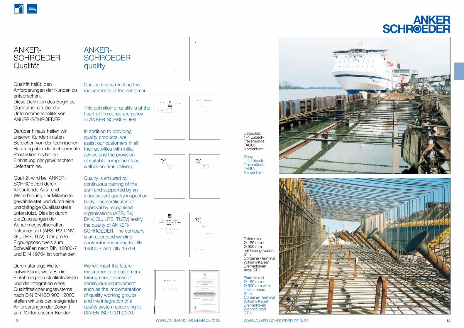
Liegeplatz 1-4 Lübeck-Travemünde TAGU; Nordenham
Quay 1-4 Lübeck-Travemünde TAGU; Nordenham
Plate tie rod Ø 180 mm / Ø 500 mm with inside thread 5“ for Container Terminal Wilhelm Kaisen BremerhavenWorking pool CT III
Telleranker Ø 180 mm / Ø 500 mmmit Innengewinde 5“ für Container-Terminal Wilhelm Kaisen BremerhavenArge CT III
14 WWW.ANKER-SCHROEDER.DE © 09 15WWW.ANKER-SCHROEDER.DE © 09
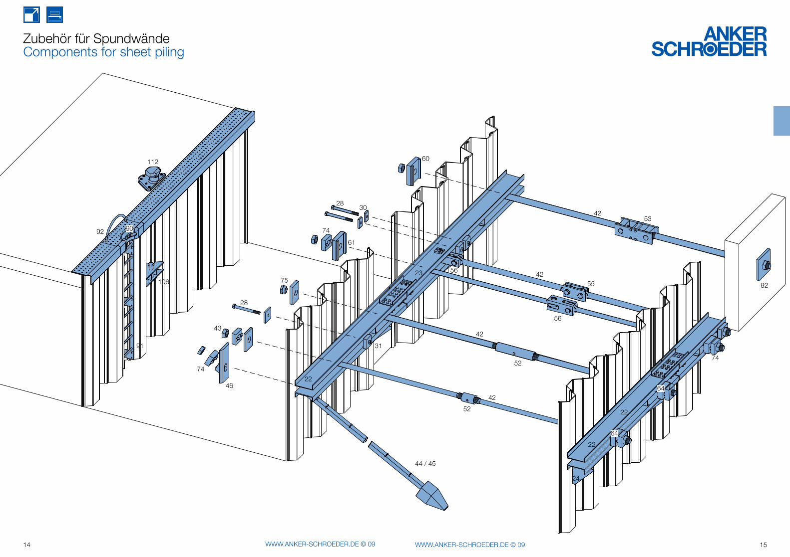
Zubehör für SpundwändeComponents for sheet piling
91
74
106
9092
112
2830
28
74
61
75
22
31
46
43
44 / 45
60
56
4253
4255
56
42
52
52
42
23
22
22
64
74
82
24
64
16 WWW.ANKER-SCHROEDER.DE © 09 17WWW.ANKER-SCHROEDER.DE © 09
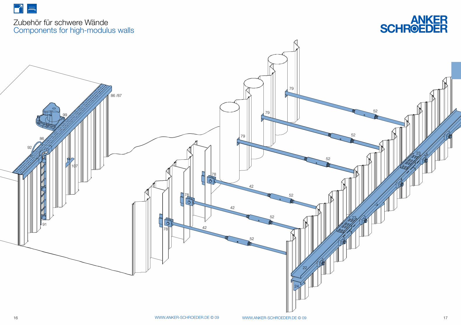
Zubehör für schwere Wände Components for high-modulus walls
78
78
78
92
99
86 /87
107
86
9142
79
23
42
42
52
52
52
52
52
52
22
24
23
79
79
18 WWW.ANKER-SCHROEDER.DE © 09 19WWW.ANKER-SCHROEDER.DE © 09
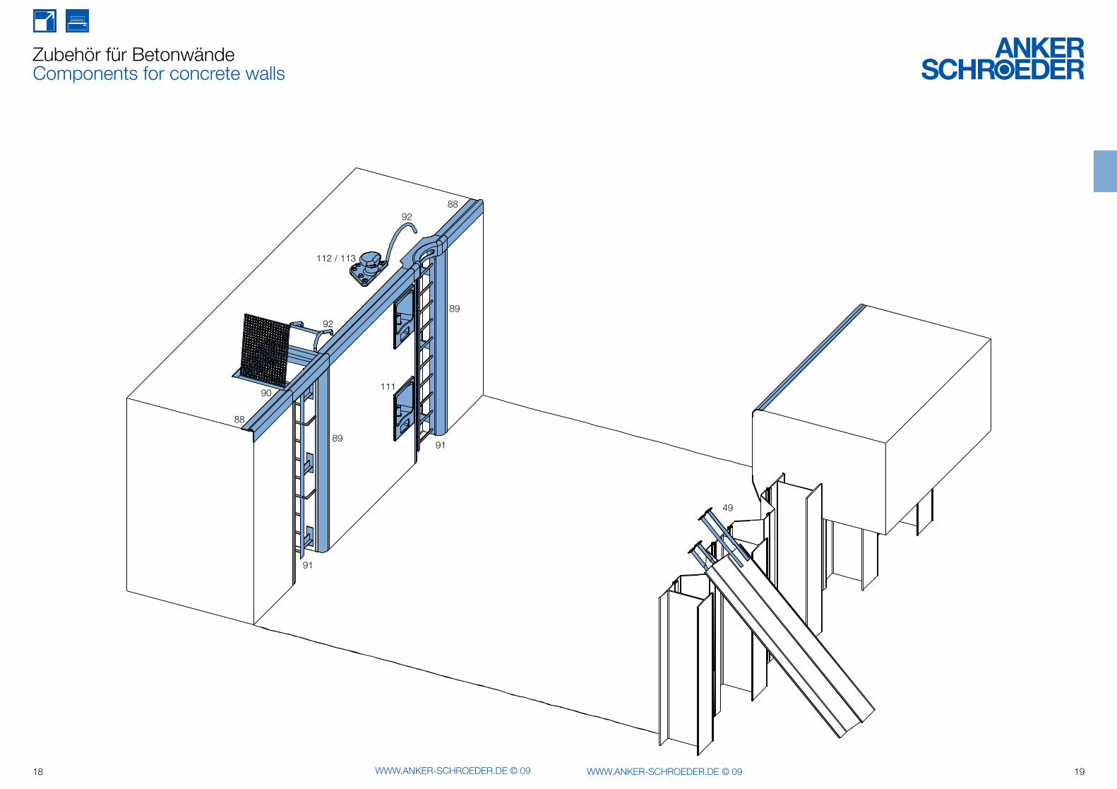
Zubehör für BetonwändeComponents for concrete walls
8892
112 / 113
89
91
111
92
90
88
91
89
49
20 WWW.ANKER-SCHROEDER.DE © 09 21WWW.ANKER-SCHROEDER.DE © 09
A C A
B
C AA
A C A
B
C AA
A C A
B
C AA
A C A
B
AA
ba
l
f
e
SW
f
2eC
y
22 WWW.ANKER-SCHROEDER.DE © 09 23WWW.ANKER-SCHROEDER.DE © 09
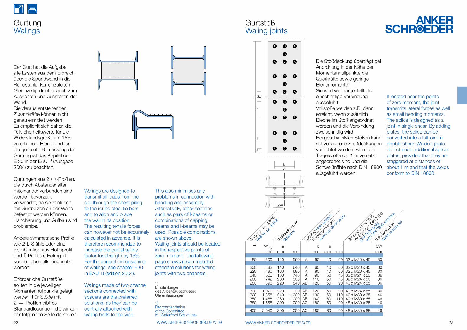
Der Gurt hat die Aufgabe alle Lasten aus dem Erdreich über die Spundwand in die Rundstahlanker einzuleiten. Gleichzeitig dient er auch zum Ausrichten und Aussteifen der Wand. Die daraus entstehenden Zusatzkräfte können nicht genau ermittelt werden. Es empfiehlt sich daher, die Teilsicherheitswerte für die Widerstandsgröße um 15% zu erhöhen. Hierzu und für die generelle Bemessung der Gurtung ist das Kapitel der E 30 in der EAU 1) (Ausgabe 2004) zu beachten.
Gurtungen aus 2 [ -Profilen, die durch Abstandshalter miteinander verbunden sind, werden bevorzugt verwendet, da sie zentrisch mit Gurtbolzen an der Wand befestigt werden können. Handhabung und Aufbau sind problemlos.
Andere symmetrische Profile wie 2 I-Stähle oder eine Kombination aus Holmprofil und I-Profil als Holmgurt können ebenfalls eingesetzt werden.
Erforderliche Gurtstöße sollten in die jeweiligen Momentennullpunkte gelegt werden. Für Stöße mit 2 [ -Profilen gibt es Standardlösungen, die wir auf der folgenden Seite darstellen.
Walings are designed to transmit all loads from the soil through the sheet piling to the round steel tie bars and to align and brace the wall in its position.The resulting tensile forces can however not be accurately calculated in advance. It is therefore recommended to increase the partial safety factor for strength by 15%. For the general dimensioning of walings, see chapter E30 in EAU 1) (edition 2004).
Walings made of two channel sections connected with spacers are the preferred solutions, as they can be centrally attached with waling bolts to the wall.
1)Empfehlungen des Arbeitsausschusses Ufereinfassungen
1)Recommendationof the Committee for Waterfront Structures
GurtungWalings
If located near the points of zero moment, the joint transmits lateral forces as well as small bending moments. The splice is designed as a joint in single shear. By adding plates, the splice can be converted into a full joint in double shear. Welded joints do not need additional splice plates, provided that they are staggered at distances of about 1 m and that the welds conform to DIN 18800.
Die Stoßdeckung überträgt bei Anordnung in der Nähe der Momentennullpunkte dieQuerkräfte sowie geringe Biegemomente.Sie wird wie dargestellt als einschnittige Verbindung ausgeführt.Vollstöße werden z.B. dann erreicht, wenn zusätzlichBleche im Stoß angeordnet werden und die Verbindung zweischnittig wird. Bei geschweißten Stößen kann auf zusätzliche Stoßdeckungen verzichtet werden, wenn die Trägerstöße ca. 1 m versetzt angeordnet sind und die Schweißnähte nach DIN 18800 ausgeführt werden.
GurtstoßWaling joints
This also minimises any problems in connection with handling and assembly.Alternatively, other sections such as pairs of I-beams or combinations of capping beams and I-beams may be used. Possible combinations are shown above.Waling joints should be located in the respective points of zero moment. The following page shows recommended standard solutions for waling joints with two channels.
][ Wel.y a l b e f SW cm3 mm mm mm mm mm mm
180 300 140 560 A 60 40 60 32 x M20 x 45 30
200 382 140 640 A 60 40 60 32 x M20 x 45 30 220 490 160 680 A 80 40 60 32 x M20 x 45 30 240 600 180 740 A 90 50 75 32 x M24 x 50 36 260 742 200 800 A 110 50 75 32 x M24 x 50 36 280 896 220 840 AB 120 50 90 40 x M24 x 55 36
300 1 070 220 920 AB 120 50 90 40 x M24 x 55 36 320 1 358 240 1 000 AB 130 60 110 40 x M30 x 65 46 350 1 468 260 1 000 AB 140 60 110 40 x M30 x 65 46 380 1 658 300 1 000 AC 180 60 90 48 x M30 x 65 46
400 2 040 300 1 000 AC 180 60 90 48 x M30 x 65 46
Loch
bild
Hole p
attern
Schrau
benDIN
7990
DIN 79
90 b
olts
Gurtun
g
(UPN)
[[
Wali
ng
(U
PN)
[[
Stoßd
ecku
ng[[
Einzela
bmes
sung
Splice
[[
Individ
ual d
imen
sions
Schlüs
selw
eite
with D
IN 79
89 w
ashe
rs
mit Sch
eiben
DIN79
89
Widt
h acro
ss fla
t
C
50
50
24 WWW.ANKER-SCHROEDER.DE © 09 25WWW.ANKER-SCHROEDER.DE © 09
GurtkonsoleSupporting brackets
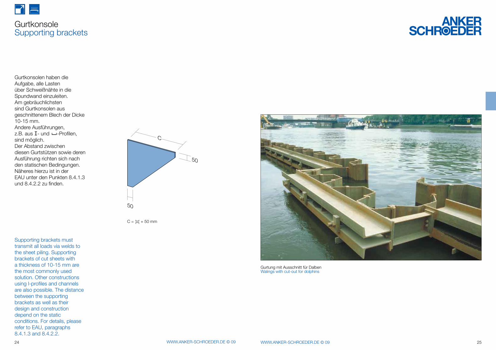
Gurtkonsolen haben die Aufgabe, alle Lasten über Schweißnähte in die Spundwand einzuleiten.Am gebräuchlichsten sind Gurtkonsolen aus geschnittenem Blech der Dicke 10-15 mm. Andere Ausführungen, z.B. aus I- und [ -Profilen, sind möglich.Der Abstand zwischen diesen Gurtstützen sowie deren Ausführung richten sich nach den statischen Bedingungen. Näheres hierzu ist in der EAU unter den Punkten 8.4.1.3 und 8.4.2.2 zu finden.
Supporting brackets must transmit all loads via welds to the sheet piling. Supporting brackets of cut sheets with a thickness of 10-15 mm are the most commonly used solution. Other constructions using I-profiles and channels are also possible. The distance between the supporting brackets as well as their design and construction depend on the static conditions. For details, please refer to EAU, paragraphs 8.4.1.3 and 8.4.2.2.
C = + 50 mm
Gurtung mit Ausschnitt für DalbenWalings with cut-out for dolphins
][
26 WWW.ANKER-SCHROEDER.DE © 09 27WWW.ANKER-SCHROEDER.DE © 09
M52
Ll
M52
L
l
l1
2
28 WWW.ANKER-SCHROEDER.DE © 09 29WWW.ANKER-SCHROEDER.DE © 09
GurtbolzenWaling bolts
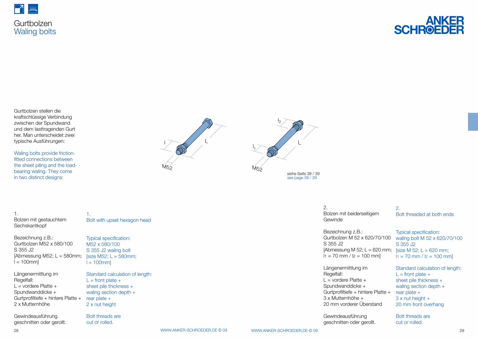
Gurtbolzen stellen die kraftschlüssige Verbindung zwischen der Spundwand und dem lasttragenden Gurt her. Man unterscheidet zwei typische Ausführungen:
Waling bolts provide friction-fitted connections between the sheet piling and the load-bearing waling. They come in two distinct designs:
1.Bolt with upset hexagon head
Typical specification:M52 x 580/100S 355 J2 waling bolt [size M52; L = 580mm; l = 100mm]
Standard calculation of length:L = front plate +sheet pile thickness + waling section depth + rear plate + 2 x nut height
Bolt threads arecut or rolled.
1.Bolzen mit gestauchtem Sechskantkopf
Bezeichnung z.B.:Gurtbolzen M52 x 580/100S 355 J2[Abmessung M52; L = 580mm; l = 100mm]
Längenermittlung im Regelfall:L = vordere Platte + Spundwanddicke + Gurtprofiltiefe + hintere Platte + 2 x Mutternhöhe
Gewindeausführung geschnitten oder gerollt.
2.Bolzen mit beiderseitigem Gewinde
Bezeichnung z.B.:Gurtbolzen M 52 x 620/70/100 S 355 J2[Abmessung M 52; L = 620 mm; l1 = 70 mm / l2 = 100 mm]
Längenermittlung imRegelfall:L = vordere Platte + Spundwanddicke + Gurtprofiltiefe + hintere Platte +3 x Mutternhöhe +20 mm vorderer Überstand
Gewindeausführung geschnitten oder gerollt.
2.Bolt threaded at both ends
Typical specification:waling bolt M 52 x 620/70/100 S 355 J2 [size M 52; L = 620 mm; l1 = 70 mm / l2 = 100 mm]
Standard calculation of length:L = front plate + sheet pile thickness +waling section depth +rear plate + 3 x nut height + 20 mm front overhang
Bolt threads are cut or rolled.
siehe Seite 38 / 39see page 38 / 39
t
b
h
Ø
t
b
h
Øt
b
h
Ø
t
b
h
Ø
30 WWW.ANKER-SCHROEDER.DE © 09 31WWW.ANKER-SCHROEDER.DE © 09
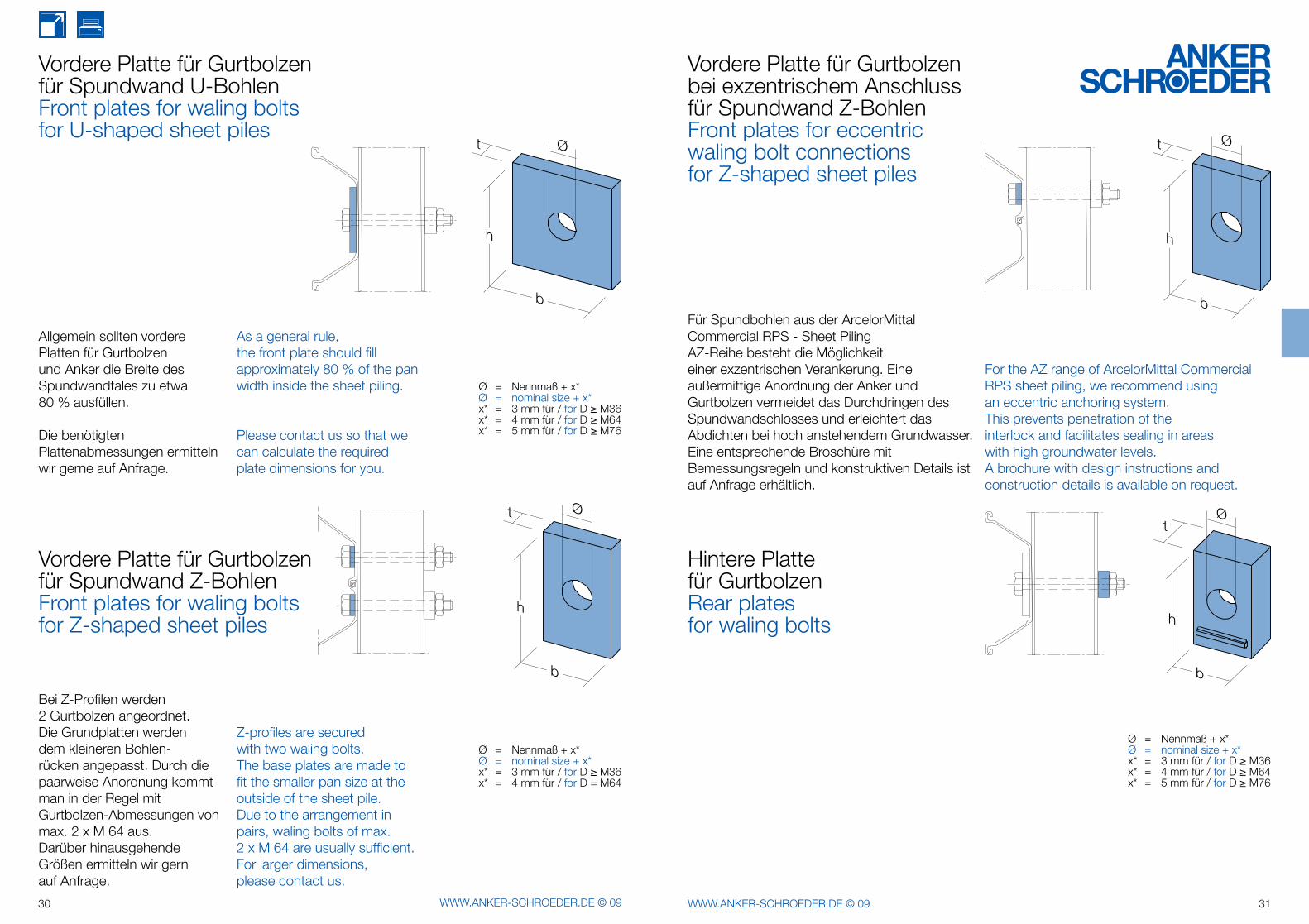
Ø = Nennmaß + x*Ø = nominal size + x*x* = 3 mm für / for D ≥ M36x* = 4 mm für / for D = M64
Vordere Platte für Gurtbolzenfür Spundwand U-BohlenFront plates for waling bolts for U-shaped sheet piles
Vordere Platte für Gurtbolzenfür Spundwand Z-BohlenFront plates for waling boltsfor Z-shaped sheet piles
Ø = Nennmaß + x*Ø = nominal size + x*x* = 3 mm für / for D ≥ M36x* = 4 mm für / for D ≥ M64x* = 5 mm für / for D ≥ M76
Allgemein sollten vordere Platten für Gurtbolzen und Anker die Breite des Spundwandtales zu etwa 80 % ausfüllen.
Die benötigten Plattenabmessungen ermitteln wir gerne auf Anfrage.
As a general rule, the front plate should fill approximately 80 % of the pan width inside the sheet piling.
Please contact us so that we can calculate the required plate dimensions for you.
Z-profiles are secured with two waling bolts.The base plates are made to fit the smaller pan size at the outside of the sheet pile.Due to the arrangement in pairs, waling bolts of max.2 x M 64 are usually sufficient. For larger dimensions, please contact us.
Bei Z-Profilen werden2 Gurtbolzen angeordnet. Die Grund platten werden dem kleineren Bohlen-rücken angepasst. Durch die paarweise Anordnung kommt man in der Regel mit Gurtbolzen-Abmessungen von max. 2 x M 64 aus.Darüber hinaus gehende Größen ermitteln wir gernauf Anfrage.
Vordere Platte für Gurtbolzenbei exzentrischem Anschlussfür Spundwand Z-BohlenFront plates for eccentric waling bolt connectionsfor Z-shaped sheet piles
Hintere Plattefür GurtbolzenRear platesfor waling bolts
Ø = Nennmaß + x*Ø = nominal size + x*x* = 3 mm für / for D ≥ M36x* = 4 mm für / for D ≥ M64x* = 5 mm für / for D ≥ M76
Für Spundbohlen aus der ArcelorMittal Commercial RPS - Sheet Piling AZ-Reihe besteht die Möglichkeit einer exzentrischen Verankerung. Eine außermittige Anordnung der Anker und Gurtbolzen vermeidet das Durchdringen des Spundwandschlosses und erleichtert das Abdichten bei hoch anstehendem Grundwasser. Eine entsprechende Broschüre mit Bemessungsregeln und konstruktiven Details ist auf Anfrage erhältlich.
For the AZ range of ArcelorMittal Commercial RPS sheet piling, we recommend using an eccentric anchoring system.This prevents penetration of the interlock and facilitates sealing in areas with high groundwater levels.A brochure with design instructions and construction details is available on request.
32 WWW.ANKER-SCHROEDER.DE © 09 33WWW.ANKER-SCHROEDER.DE © 09
34 WWW.ANKER-SCHROEDER.DE © 09 35WWW.ANKER-SCHROEDER.DE © 09
Warum aufgestauchte Rundstahlanker?Why using upset round steel tie rods?
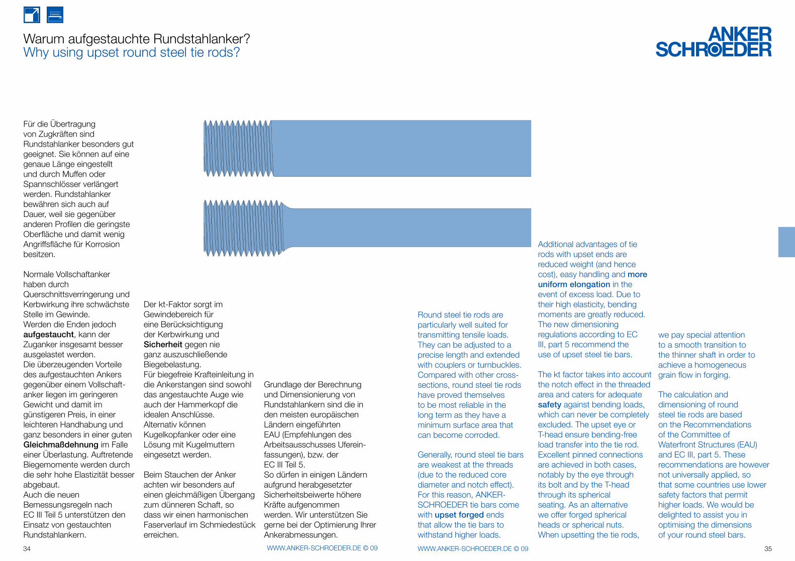
Für die Übertragung von Zugkräften sind Rundstahlanker besonders gutgeeignet. Sie können auf eine genaue Länge eingestellt und durch Muffen oder Spannschlösser verlängert werden. Rundstahlanker bewähren sich auch auf Dauer, weil sie gegenüber anderen Profilen die geringste Oberfläche und damit wenig Angriffs fläche für Korrosion besitzen.
Normale Vollschaftankerhaben durch Querschnittsverringerung und Kerb wirkung ihre schwächste Stelle im Gewinde. Werden die Enden jedoch aufgestaucht, kann der Zuganker insgesamt besser ausgelastet werden.Die überzeugenden Vorteile des aufgestauchten Ankers gegenüber einem Vollschaft-anker liegen im geringeren Gewicht und damit im günstigeren Preis, in einer leichteren Handhabung und ganz besonders in einer guten Gleichmaßdehnung im Falle einer Überlastung. Auftretende Biegemomente werden durch die sehr hohe Elastizität besser abgebaut.Auch die neuen Bemessungsregeln nach EC III Teil 5 unterstützen den Einsatz von gestauchten Rundstahlankern.
Der kt-Faktor sorgt im Gewindebereich für eine Berücksichtigung der Kerbwirkung und Sicher heit gegen nie ganz auszuschließende Biegebelastung.Für biegefreie Kraft einleitung in die Ankerstangen sind sowohl das angestauchte Auge wie auch der Hammerkopf die idealen Anschlüsse.Alternativ können Kugelkopfanker oder eine Lösung mit Kugelmuttern eingesetzt werden.
Beim Stauchen der Anker achten wir besonders auf einen gleichmäßigen Übergang zum dünneren Schaft, so dass wir einen harmonischen Faserverlauf im Schmiedestück erreichen.
Grundlage der Berechnung und Dimensionierung von Rundstahlankern sind die in den meisten europäischen Ländern eingeführten EAU (Empfehlungen des Arbeitsausschusses Uferein-fassungen), bzw. derEC III Teil 5. So dürfen in einigen Ländern aufgrund herabgesetzter Sicherheitsbeiwerte höhere Kräfte aufgenommen werden. Wir unterstützen Sie gerne bei der Optimierung Ihrer Ankerabmessungen.
Round steel tie rods are particularly well suited for transmitting tensile loads. They can be adjusted to a precise length and extended with couplers or turnbuckles. Compared with other cross-sections, round steel tie rods have proved themselves to be most reliable in the long term as they have a minimum surface area that can become corroded.
Generally, round steel tie bars are weakest at the threads(due to the reduced core diameter and notch effect). For this reason, ANKER-SCHROEDER tie bars come with upset forged ends that allow the tie bars to withstand higher loads.
Additional advantages of tie rods with upset ends are reduced weight (and hence cost), easy handling and more uniform elongation in the event of excess load. Due to their high elasticity, bending moments are greatly reduced. The new dimensioning regulations according to EC III, part 5 recommend the use of upset steel tie bars.
The kt factor takes into account the notch effect in the threaded area and caters for adequate safety against bending loads, which can never be completely excluded. The upset eye or T-head ensure bending-free load transfer into the tie rod.Excellent pinned connections are achieved in both cases, notably by the eye through its bolt and by the T-head through its spherical seating. As an alternative we offer forged spherical heads or spherical nuts.When upsetting the tie rods,
we pay special attention to a smooth transition to the thinner shaft in order to achieve a homogeneous grain flow in forging.
The calculation and dimensioning of round steel tie rods are based on the Recommendations of the Committee of Waterfront Structures (EAU) and EC III, part 5. These recommendations are however not universally applied, so that some countries use lower safety factors that permit higher loads. We would be delighted to assist you in optimising the dimensions of your round steel bars.
36 WWW.ANKER-SCHROEDER.DE © 09 37WWW.ANKER-SCHROEDER.DE © 09
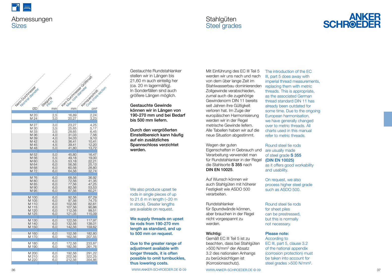
AbmessungenSizes
Gestauchte Rundstahlanker stellen wir in Längen bis 21,60 m auch einteilig her (ca. 20 m lagermäßig).In Sonderfällen sind auch größere Längen möglich.
Gestauchte Gewinde können wir in Längen von190-270 mm und bei Bedarf bis 500 mm liefern.
Durch den ver größerten Einstellbereich kann häufigauf ein zusätzlichesSpannschloss verzichtet werden.
We also produce upset tie rods in single pieces of up to 21.6 m in length (~20 m in stock). Greater lengths are available on request.
We supply threads on upset tie rods from 190-270 mm length as standard, and up to 500 mm on request.
Due to the greater range of adjustment available with longer threads, it is often possible to omit turnbuckles, thus lowering costs.
Mit Einführung des EC III Teil 5 werden wir uns nach und nach von dem über lange Zeit im Stahlwasserbau dominierenden Zollgewinde verabschieden, zumal auch die zugehörige Gewindenorm DIN 11 bereits seit Jahren ihre Gültigkeit verloren hat. Im Zuge der europäischen Harmonisierung werden wir in der Regel metrische Gewinde liefern.Alle Tabellen haben wir auf die neue Situation abgestimmt.
Wegen der guten Eigenschaften in Gebrauch und Verarbeitung verwendet man für Rundstahlanker in der Regel die Stahlsorte S 355 nach DIN EN 10025.
Auf Wunsch können wir auch Stahlgüten mit höherer Festigkeit wie ASDO 500 verarbeiten.
Rundstahlanker für Spund wände können,aber brauchen in der Regel nicht vorgespannt zuwerden.
Wichtig:Gemäß EC III Teil 5 ist zu beachten, dass bei Stahlgüten >500 N/mm2 der Absatz 3.2 des nationalen Anhangs zu berücksichtigen ist (Korrosionsschutz).
StahlgütenSteel grades
The introduction of the EC III, part 5 does away with imperial thread measurements, replacing them with metric threads. This is appropriate, as the associated German thread standard DIN 11 has already been outdated for some time. Due to the ongoing European harmonisation, we have generally changed over to metric threads. All charts used in this manual refer to metric threads.
Round steel tie rods are usually made of steel grade S 355 (DIN EN 10025) as it offers good workability and usability.
On request, we also process higher steel grade such as ASDO 500.
Round steel tie rods for sheet piles can be prestressed, but this is normally not necessary.
Please note:According to EC III, part 5, clause 3.2 of the national appendix (corrosion protection) must be taken into account for steel grades >500 N/mm².
ØD mm mm cm²
M 20 2,5 16,89 2,24 M 24 3,0 20,27 3,23
M 27 3,0 23,27 4,25 M 30 3,5 25,65 5,17 M 33 3,5 28,65 6,45 M 36 4,0 31,03 7,56 M 39 4,0 34,03 9,10 M 42 4,5 36,41 10,41 M 45 4,5 39,41 12,20 M 48 5,0 41,80 13,72
M 52 5,0 45,80 16,47 M 56 5,5 49,18 19,00 M 60 5,5 53,18 22,21 M 64 6,0 56,56 25,13 M 68 6,0 60,56 28,80 M 72 6,0 64,56 32,74
M 76 6,0 68,56 36,92 M 80 6,0 72,56 41,35 M 85 6,0 77,56 47,25 M 90 6,0 82,56 53,53 M 95 6,0 87,56 60,21
M 100 6,0 92,56 67,29 M 105 6,0 97,56 74,75 M 110 6,0 102,56 82,61 M 115 6,0 107,56 90,86 M 120 6,0 112,56 99,51 M 125 6,0 121,05 115,09
M 130 6,0 122,56 117,97 M 140 6,0 132,56 138,01 M 150 6,0 142,56 159,62
M 160 6,0 152,56 182,80 M 170 6,0 162,56 207,55
M 180 6,0 172,56 233,87 M 190 6,0 182,56 261,76 M 200 6,0 192,56 291,22 M 210 6,0 202,56 322,25 M 220 6,0 212,56 354,86
Pitch
Steigu
ng
Nomina
l diam
eter
Nenn-
Durchm
esse
r
Max. c
ore d
iamete
r
Kern-
Durchm
esse
r Größtm
aß
Core c
ross
-sec
tion
Kernq
uersc
hnitt
38 WWW.ANKER-SCHROEDER.DE © 09 39WWW.ANKER-SCHROEDER.DE © 09
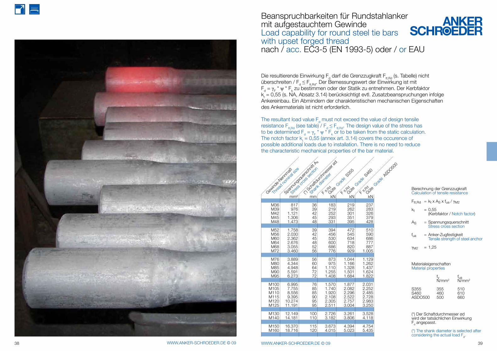
Die resultierende Einwirkung Fd darf die Grenzzugkraft Ftt,Rd (s. Tabelle) nicht überschreiten / Fd ≤ Ftt,Rd. Der Bemessungswert der Einwirkung ist mit Fd = γF * ψ * Fk zu bestimmen oder der Statik zu entnehmen. Der Kerbfaktor kt = 0,55 (s. NA, Absatz 3.14) berücksichtigt evtl. Zusatzbeanspruchungen infolge Ankereinbau. Ein Abmindern der charakteristischen mechanischen Eigenschaften des Ankermaterials ist nicht erforderlich.
The resultant load value Fd must not exceed the value of design tensile resistance Ftt,Rd (see table) / Fd ≤ Ftt,Rd. The design value of the stress has to be determined Fd = γF * ψ * Fk or to be taken from the static calculation. The notch factor kt = 0,55 (annex art. 3.14) covers the occurence of possible additional loads due to installation. There is no need to reduce the characteristic mechanical properties of the bar material.
Beanspruchbarkeiten für Rundstahlanker mit aufgestauchtem GewindeLoad capability for round steel tie bars with upset forged threadnach / acc. EC3-5 (EN 1993-5) oder / or EAU
Berechnung der GrenzzugkraftCalculation of tensile resistance
Ftt,Rd = kt x AS x fua / γM2
kt = 0,55 (Kerbfaktor / Notch factor)
AS = Spannungsquerschnitt Stress cross section
fua = Anker-Zugfestigkeit Tensile strength of steel anchor
γM2 = 1,25
(*) Der Schaftdurchmesser ød wird der tatsächlichen Einwirkung Fd angepasst.
(*) The shank diameter is selected after considering the actual load Fd.
MaterialeigenschaftenMaterial properties
fy fua N/mm2 N/mm2
S355 355 510S460 460 610ASDO500 500 660
mm² mm kN kN kN
M36 817 36 183 219 237 M39 976 39 219 262 283 M42 1.121 42 252 301 326 M45 1.306 45 293 351 379 M48 1.473 48 331 395 428
M52 1.758 39 394 472 510 M56 2.030 42 456 545 590 M60 2.362 45 530 634 686 M64 2.676 48 600 718 777 M68 3.055 52 686 820 887 M72 3.460 56 776 929 1.005
M76 3.889 56 873 1.044 1.129 M80 4.344 60 975 1.166 1.262 M85 4.948 64 1.110 1.328 1.437 M90 5.591 72 1.255 1.501 1.624 M95 6.273 72 1.408 1.684 1.822
M100 6.995 76 1.570 1.877 2.031 M105 7.755 85 1.740 2.082 2.252 M110 8.556 85 1.920 2.296 2.485 M115 9.395 90 2.108 2.522 2.728 M120 10.274 95 2.305 2.757 2.983 M125 11.191 95 2.511 3.004 3.250
M130 12.149 100 2.726 3.261 3.528 M140 14.181 110 3.182 3.806 4.118
M150 16.370 115 3.673 4.394 4.754 M160 18.716 120 4.015 5.023 5.435
Threa
d no
minal s
ize
Gewind
e-Nen
nmaß
F tt,R
d
Güte G
rade
S460
Güte G
rade
ASDO500
F tt,R
d
Stress
cros
s sec
tion
Spann
ungs
quers
chnit
t As
Shank
diam
eter
(*) Sch
aftdu
rchmes
ser ø
d
Güte G
rade
S355
F tt,R
d
40 WWW.ANKER-SCHROEDER.DE © 09 41WWW.ANKER-SCHROEDER.DE © 09
Korrosionsschutz von RundstahlankernCorrosion protection of round steel tie rods
Wenn die ermittelten Ankerdurchmesser um 2-5 mm erhöht werden, kann auf einen kostspieligen und empfindlichen Korrosionsschutz verzichtet werden.
Die somit erhöhte Lebens-dauer bei Verlegung der Anker im Kiesbett ist in den meisten Fällen ausreichend.
Wenn man glaubt, an der Küste (im Tidebereich) oder in aggressiven Böden nicht auf einen zusätzlichen Korrosionsschutz verzichten zu können, kommen 5 weitere Möglichkeiten in Frage:
1. Feuerverzinkung2. Feuerverzinkung mit zusätzlichem Anstrich3. Anstrich-Komplett- systeme (verschiedener Hersteller) - auf Bitumenbasis (Teerepoxy) - auf Kunststoffbasis4. Schrumpfschlauch- Systeme5. Band-Umwicklung
Zu diesem komplexen Thema beraten wir Sie gern entsprechend Ihren Anforde-rungen. Wir arbeiten in diesem Bereich eng mit ver-schiedenen Fachfirmen zu-sammen und können Ihnen die gewünschten
Schutzsysteme anbieten. Die Arbeiten sind teilweise auch nach dem Einbau auf der Baustelle möglich.Bei feuerverzinkten Ankern können die Gewinde gering-fügig unterschnitten werden, so dass beim Nachschneiden noch ein Teil der Verzinkung im Gewindebereich verbleibt. Unvermeidliche Fehlstellen müssen gegebenenfalls kalt nachgearbeitet werden.
Gewinde müssen vor dem Sandstrahlen sehr gut ge-schützt und nachher intensiv gereinigt werden! Beim Strahlen sollten keine Muttern oder Spannschlös-ser aufgezogen sein.
A cost-effective method to protect steel tie rods against corrosion is simply to increase the calculated diameter by 2 to 5 mm.
The resulting increased design life is normally sufficient for tie rods installed in the aggregate bed. On the coast (in tidal areas) or in corrosive soils, there might be a need for extra protection against corrosion.For this purpose, we recommend five options:
1. Hot-dip galvanizing 2. Hot-dip galvanizing with additional protective coating 3. Complete coating systems (available from various manufacturers) -based on bitumen (tar epoxy) -based on plastics 4. Hot-shrink sleeve systems 5. Wrapping
We would be delighted to assist you in assessing the necessary for such complex solutions in accordance with your requirements. In the field of corrosion protection, we cooperate closely with various specialised subcontractors
and can offer you any coating you require. Some protective coatings can even be applied after installation. The threads of hot-dip galva-nized tie rods can be slightly undercut so that some of the galvanizing coat remains on the threaded ends after recut-ting. Such unavoidable de-fects might need to be cold-reworked.
Threads must be carefully protected before the rods are sand blasted and properly cleaned afterwards! Ensure that all nuts and turnbuckles are removed before sand-blasting the rods.
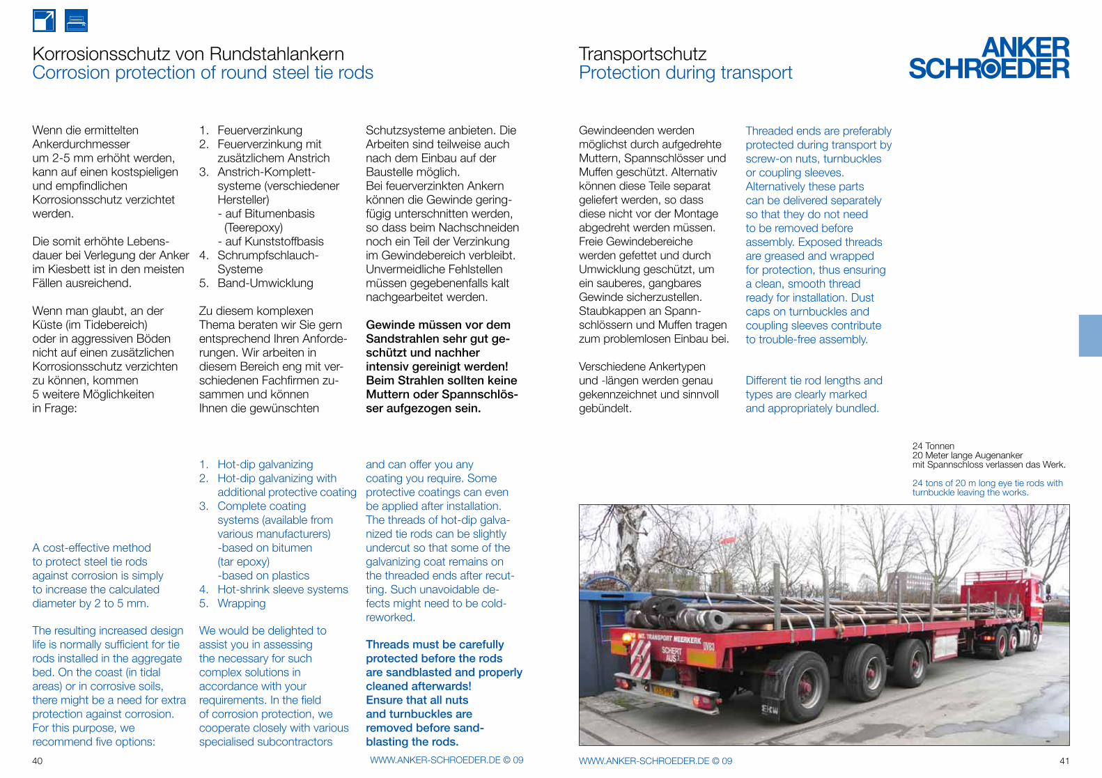
TransportschutzProtection during transport
Gewindeenden werdenmöglichst durch aufgedrehte Muttern, Spannschlösser und Muffen geschützt. Alternativ können diese Teile separat geliefert werden, so dass diese nicht vor der Montage abgedreht werden müssen. Freie Gewinde bereiche werden gefettet und durch Umwicklung geschützt, um ein sauberes, gangbares Gewinde sicherzustellen. Staubkappen an Spann-schlössern und Muffen tragen zum problemlosen Einbau bei.
Verschiedene Ankertypen und -längen werden genau gekennzeichnet und sinnvoll gebündelt.
Threaded ends are preferably protected during transport by screw-on nuts, turnbuckles or coupling sleeves. Alternatively these parts can be delivered separately so that they do not need to be removed before assembly. Exposed threads are greased and wrapped for protection, thus ensuring a clean, smooth thread ready for installation. Dust caps on turnbuckles and coupling sleeves contribute to trouble-free assembly.
Different tie rod lengths and types are clearly marked and appropriately bundled.
24 Tonnen 20 Meter lange Augenankermit Spannschloss verlassen das Werk.
24 tons of 20 m long eye tie rods with turnbuckle leaving the works.
ØD
b1
ØD
b
ØD
Ød
b
ka2
m
ØD
Ød
b
ød2
ØD
lv
hv hg
ØD
Ød
b
lgh
E
sw
42 WWW.ANKER-SCHROEDER.DE © 09 43WWW.ANKER-SCHROEDER.DE © 09
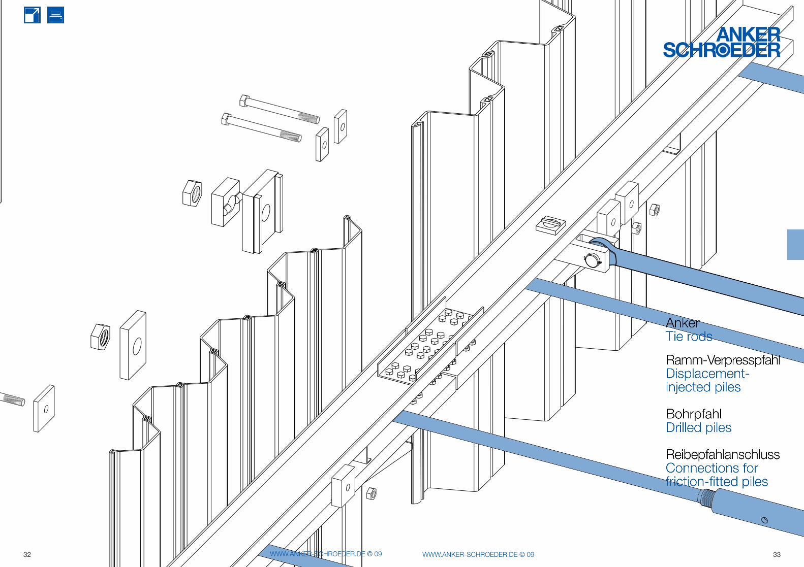
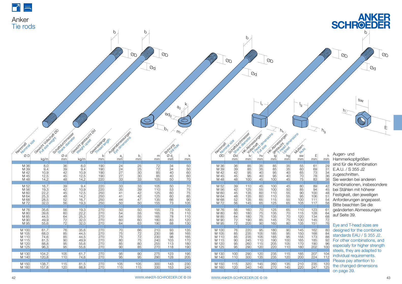
AnkerTie rods
Augen- und Hammerkopfgrößen sind für die Kombination E.A.U. / S 355 J2 zugeschnitten. Sie werden bei anderen Kombinationen, insbesondere bei Stählen mit höherer Festigkeit, den jeweiligen Anforderungen angepasst.Bitte beachten Sie die geänderten Abmessungen auf Seite 39.
Eye and T-head sizes are designed for the combined standards EAU / S 355 J2.For other combinations, and especially for higher strength steels, they are adapted to individual requirements.Please pay attention to the changed dimensions on page 39.
ØD Ød lv hv lg hg sw E h mm mm mm mm mm mm mm mm M 36 36 85 35 85 35 55 61 29 M 39 39 85 35 85 35 60 69 31 M 42 42 95 40 95 40 65 73 34 M 45 45 95 40 95 40 70 78 36 M 48 48 100 45 100 45 75 83 38
M 52 39 110 45 100 45 80 89 42 M 56 42 125 55 100 50 85 94 45 M 60 45 135 60 110 55 90 100 48 M 64 48 135 60 110 55 95 106 51 M 68 52 135 65 115 55 100 111 54 M 72 56 145 65 125 65 105 117 58
M 76 56 160 70 125 65 110 123 61 M 80 60 180 75 135 70 115 128 64 M 85 64 180 75 135 70 120 134 68 M 90 72 190 85 145 75 130 145 72 M 95 72 205 90 160 80 135 151 76 M 100 76 220 95 180 90 145 162 80 M 105 85 235 105 185 95 150 168 84 M 110 85 235 105 185 95 155 173 88 M 115 90 245 110 190 100 165 185 92 M 120 95 260 115 205 105 170 190 96 M 125 95 290 120 220 110 180 202 100
M 130 100 290 120 235 115 185 207 104 M 140 110 300 135 235 120 200 224 112
M 150 115 320 145 260 135 210 235 120 M 160 120 340 145 270 145 220 247 125
Ø D Ø d b a2 b1 m Ø d2 k kg/m mm kg/m mm mm mm mm mm mm M 36 8,0 36 8,0 190 24 25 72 34 50 M 39 9,4 39 9,4 190 24 25 72 34 50 M 42 10,9 42 10,9 190 27 30 85 40 60 M 45 12,5 45 12,5 190 27 30 85 40 60 M 48 14,2 48 14,2 220 33 33 105 50 70
M 52 16,7 39 9,4 220 33 33 105 50 70 M 56 19,3 42 10,9 220 35 39 110 53 75 M 60 22,2 45 12,5 250 41 42 125 60 75 M 64 25,3 48 14,2 250 41 42 125 60 85 M 68 28,5 52 16,7 250 44 47 135 66 90 M 72 32,0 56 19,3 250 50 50 155 73 105
M 76 35,6 56 19,3 270 50 50 155 73 105 M 80 39,6 60 22,2 270 54 55 165 78 110 M 85 44,5 64 25,3 270 54 55 165 78 110 M 90 49,9 72 32,0 270 60 60 180 83 120 M 95 55,6 72 32,0 270 64 63 190 88 130
M 100 61,7 76 35,6 270 70 66 210 93 135 M 105 68,0 85 44,5 270 75 72 230 98 165 M 110 74,6 85 44,5 270 75 72 230 98 165 M 115 81,5 90 49,9 270 80 75 240 103 170 M 120 88,8 95 55,6 270 85 80 255 113 180 M 125 96,3 95 55,6 270 90 85 270 118 190
M 130 104,2 105 61,7 270 95 90 275 123 195 M 140 120,8 110 74,6 270 95 95 290 128 205
M 150 138,7 115 81,5 270 105 105 300 143 230 M 160 157,8 120 88,8 270 115 115 330 153 240
Shank
diam
eter
Schaft
durch
messe
r
Nomina
l size
Nennm
aß
Weig
ht up
set
Gewich
t ges
tauch
t Ød
Threa
d len
gth
Gewind
eläng
e
Eye d
imen
sions
Augen
abmes
sung
en
Drill ho
le
Bohru
ng
Full s
ize w
eight
Gewich
t Voll
scha
ft ØD
Shank
diam
eter
Schaft
durch
messe
r
Nomina
l size
Nennm
aß
Vollsc
haft
HK-Abm
essu
ngen
NutsMut
tern
Full s
ize
T-he
ad d
imen
sions
gesta
ucht
HK-Abm
essu
ngen
Upset
T-he
ad d
imen
sions
44 WWW.ANKER-SCHROEDER.DE © 09 45WWW.ANKER-SCHROEDER.DE © 09
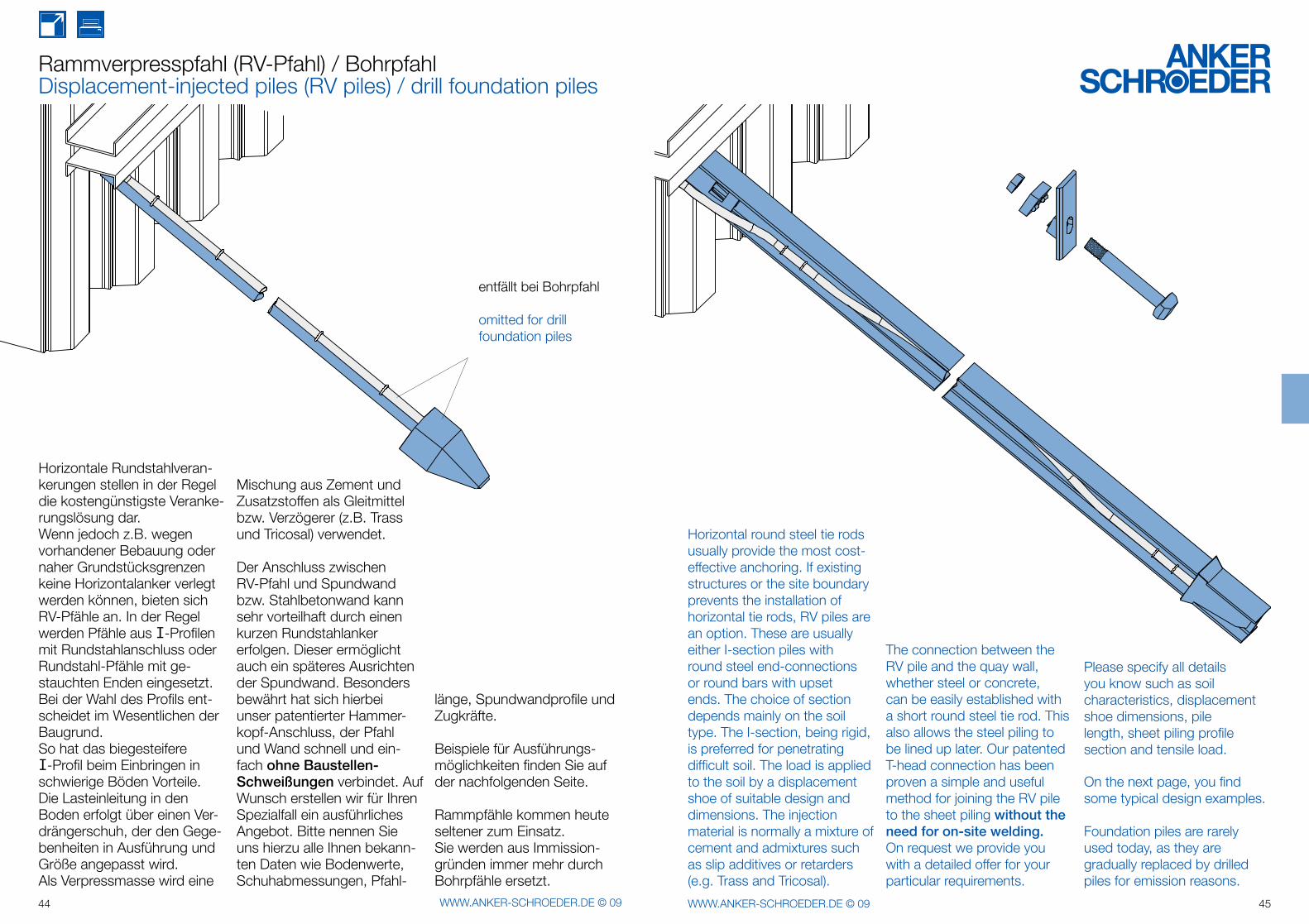
Horizontale Rundstahlveran-kerungen stellen in der Regel die kosten günstig ste Veranke-rungslösung dar. Wenn jedoch z.B. wegen vorhandener Bebau ung oder naher Grundstücksgrenzen keine Horizontalanker verlegt werden können, bieten sich RV-Pfähle an. In der Regel werden Pfähle aus I-Profilen mit Rundstahlanschluss oder Rund stahl-Pfähle mit ge-stauchten Enden eingesetzt. Bei der Wahl des Profils ent-scheidet im Wesentlichen der Baugrund.So hat das biegesteifereI-Profil beim Einbringen in schwierige Böden Vorteile.Die Lasteinleitung in den Boden erfolgt über einen Ver-drängerschuh, der den Gege-benheiten in Ausführung und Größe angepasst wird. Als Verpressmasse wird eine
Mischung aus Zement und Zusatzstoffen als Gleitmittel bzw. Verzögerer (z.B. Trass und Tricosal) verwendet.
Der Anschluss zwischen RV-Pfahl und Spundwand bzw. Stahlbetonwand kann sehr vorteilhaft durch einen kurzen Rundstahlanker erfolgen. Dieser ermöglicht auch ein späteres Ausrichten der Spundwand. Besonders bewährt hat sich hierbei unser patentierter Hammer-kopf-Anschluss, der Pfahl und Wand schnell und ein-fach ohne Baustellen-Schweißungen verbindet. Auf Wunsch erstellen wir für Ihren Spezialfall ein ausführliches Angebot. Bitte nennen Sie uns hierzu alle Ihnen bekann-ten Daten wie Bodenwerte, Schuhabmessungen, Pfahl-
länge, Spundwandprofile und Zugkräfte.
Beispiele für Ausführungs-möglichkeiten finden Sie auf der nachfolgenden Seite.
Rammpfähle kommen heute seltener zum Einsatz. Sie werden aus Immission-gründen immer mehr durch Bohrpfähle ersetzt.
Rammverpresspfahl (RV-Pfahl) / BohrpfahlDisplacement-injected piles (RV piles) / drill foundation piles
entfällt bei Bohrpfahl
omitted for drill foundation piles
Horizontal round steel tie rods usually provide the most cost-effective anchoring. If existing structures or the site boundary prevents the installation of horizontal tie rods, RV piles are an option. These are usually either I-section piles with round steel end-connections or round bars with upset ends. The choice of section depends mainly on the soil type. The I-section, being rigid, is preferred for penetrating difficult soil. The load is applied to the soil by a displacement shoe of suitable design and dimensions. The injection material is normally a mixture of cement and admixtures such as slip additives or retarders (e.g. Trass and Tricosal).
The connection between the RV pile and the quay wall,whether steel or concrete,can be easily established with a short round steel tie rod. This also allows the steel piling to be lined up later. Our patented T-head connection has been proven a simple and useful method for joining the RV pile to the sheet piling without the need for on-site welding. On request we provide you with a detailed offer for your particular requirements.
Please specify all details you know such as soil characteristics, displacement shoe dimensions, pile length, sheet piling profile section and tensile load.
On the next page, you find some typical design examples.
Foundation piles are rarely used today, as they are gradually replaced by drilled piles for emission reasons.
46 WWW.ANKER-SCHROEDER.DE © 09 47WWW.ANKER-SCHROEDER.DE © 09
Bohrpfahl und RV-Pfahl-AnschlussDrilled foundation pile connection / RV-Pile Connection
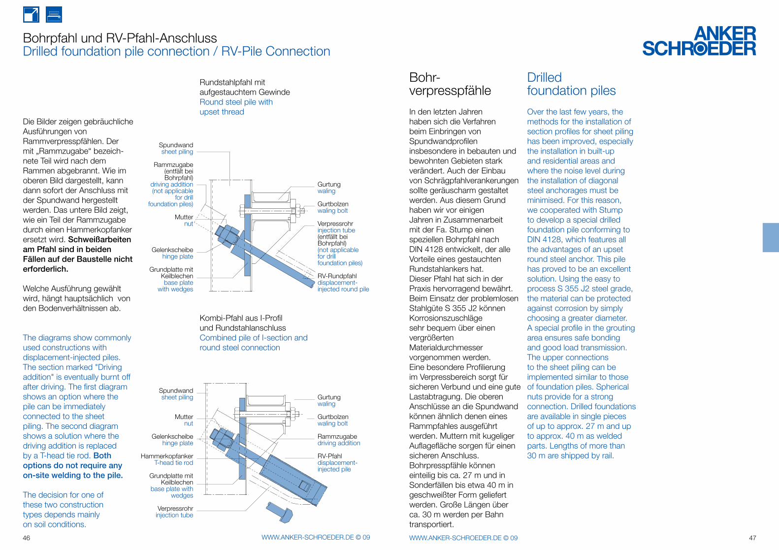
Die Bilder zeigen gebräuchliche Aus führungen von Rammverpresspfählen. Der mit „Rammzugabe“ bezeich-nete Teil wird nach dem Rammen abge brannt. Wie im oberen Bild dargestellt, kann dann sofort der Anschluss mit der Spundwand hergestellt werden. Das untere Bild zeigt, wie ein Teil der Ramm zugabe durch einen Hammerkopf anker ersetzt wird. Schweißarbeiten am Pfahl sind in beiden Fällen auf der Baustelle nicht erforderlich.
Welche Ausführung gewählt wird, hängt hauptsächlich von den Bodenver hält nissen ab.
The diagrams show commonly used constructions with displacement-injected piles. The section marked "Driving addition" is eventually burnt off after driving. The first diagram shows an option where the pile can be immediately connected to the sheet piling. The second diagram shows a solution where the driving addition is replaced by a T-head tie rod. Both options do not require any on-site welding to the pile.
The decision for one of these two construction types depends mainly on soil conditions.
Gurtungwaling
Gurtbolzenwaling bolt
Verpressrohrinjection tube(entfällt bei Bohrpfahl)(not applicable for drill foundation piles)
RV-Rundpfahldisplacement-injected round pile
Spundwandsheet piling
Mutternut
Gelenkscheibehinge plate
HammerkopfankerT-head tie rod
Grundplatte mit Keilblechen
base plate with wedges
Verpressrohrinjection tube
Gurtungwaling
Gurtbolzenwaling bolt
Rammzugabedriving addition
RV-Pfahldisplacement-injected pile
Rundstahlpfahl mitaufgestauchtem GewindeRound steel pile withupset thread
Kombi-Pfahl aus I-Profilund RundstahlanschlussCombined pile of I-section and round steel connection
Spundwandsheet piling
Rammzugabe(entfält bei Bohrpfahl)
driving addition(not applicable
for drill foundation piles)
Mutternut
Gelenkscheibehinge plate
Grundplatte mit Keilblechenbase plate
with wedges
Bohr-verpresspfähle
In den letzten Jahren haben sich die Verfahren beim Einbringen von Spundwandprofilen insbesondere in bebauten und bewohnten Gebieten stark verändert. Auch der Einbau von Schrägpfahlverankerungen sollte geräuscharm gestaltet werden. Aus diesem Grund haben wir vor einigen Jahren in Zusammenarbeit mit der Fa. Stump einen speziellen Bohrpfahl nach DIN 4128 entwickelt, der alle Vorteile eines gestauchten Rundstahlankers hat.Dieser Pfahl hat sich in der Praxis hervorragend bewährt.Beim Einsatz der problemlosen Stahlgüte S 355 J2 können Korrosionszuschläge sehr bequem über einen vergrößerten Materialdurchmesser vorgenommen werden.Eine besondere Profilierung im Verpressbereich sorgt für sicheren Verbund und eine gute Lastabtragung. Die oberen Anschlüsse an die Spundwand können ähnlich denen eines Rammpfahles ausgeführt werden. Muttern mit kugeliger Auflagefläche sorgen für einen sicheren Anschluss.Bohrpresspfähle können einteilig bis ca. 27 m und in Sonderfällen bis etwa 40 m in geschweißter Form geliefert werden. Große Längen über ca. 30 m werden per Bahn transportiert.
Drilledfoundation piles
Over the last few years, the methods for the installation of section profiles for sheet piling has been improved, especially the installation in built-up and residential areas and where the noise level during the installation of diagonal steel anchorages must be minimised. For this reason, we cooperated with Stump to develop a special drilled foundation pile conforming to DIN 4128, which features all the advantages of an upset round steel anchor. This pile has proved to be an excellent solution. Using the easy to process S 355 J2 steel grade, the material can be protected against corrosion by simply choosing a greater diameter. A special profile in the grouting area ensures safe bonding and good load transmission. The upper connections to the sheet piling can be implemented similar to those of foundation piles. Spherical nuts provide for a strong connection. Drilled foundations are available in single pieces of up to approx. 27 m and up to approx. 40 m as welded parts. Lengths of more than 30 m are shipped by rail.
ø 21
010
41
R 10 bearbeitet / machined
ø705
430
48 WWW.ANKER-SCHROEDER.DE © 09 49WWW.ANKER-SCHROEDER.DE © 09
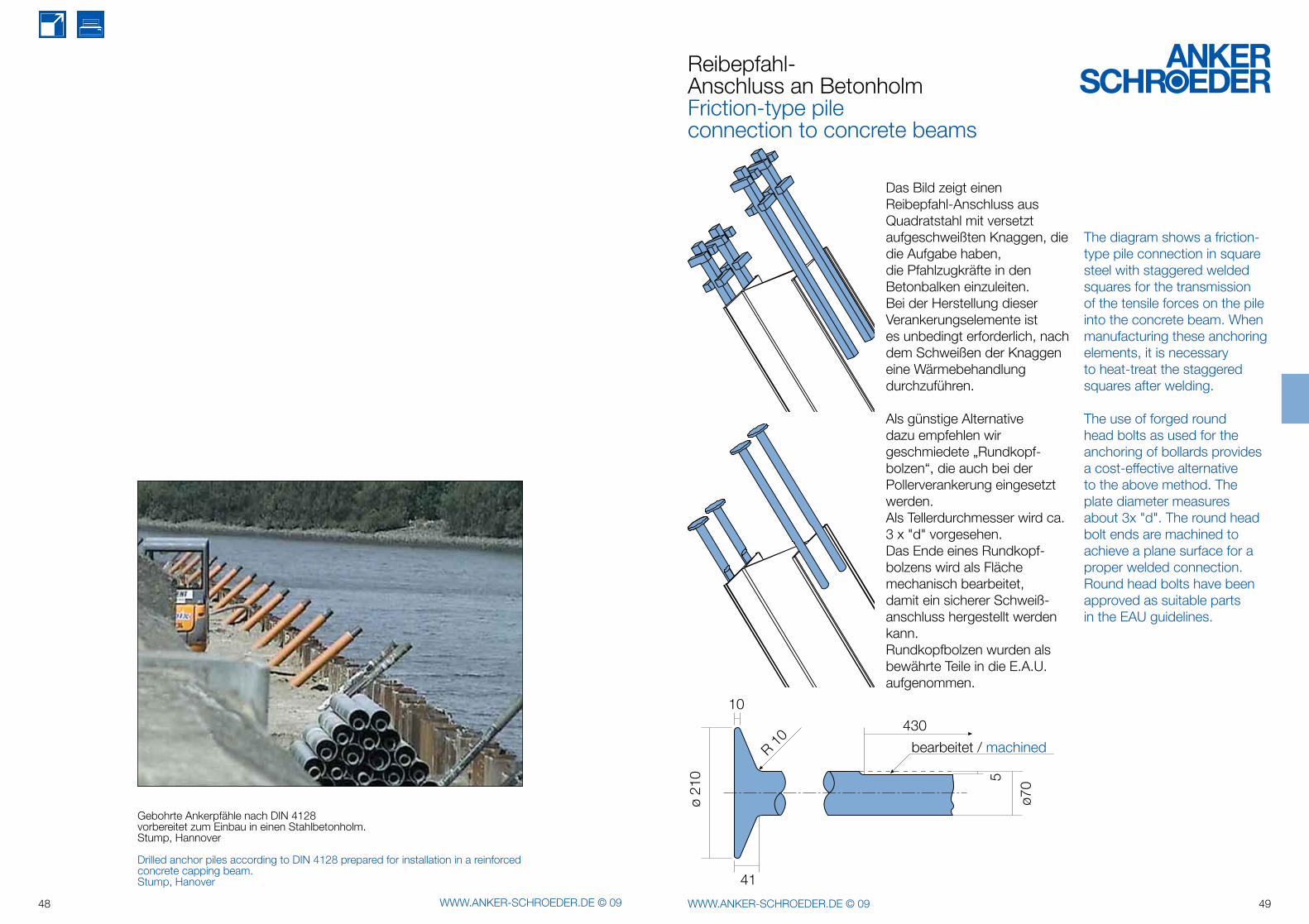
Gebohrte Ankerpfähle nach DIN 4128 vorbereitet zum Einbau in einen Stahlbetonholm.Stump, Hannover
Drilled anchor piles according to DIN 4128 prepared for installation in a reinforced concrete capping beam.Stump, Hanover
Reibepfahl-Anschluss an BetonholmFriction-type pileconnection to concrete beams
Das Bild zeigt einen Reibepfahl-Anschluss aus Quadratstahl mit ver setzt aufgeschweißten Knaggen, die die Aufgabe haben,die Pfahlzugkräfte in den Betonbalken einzuleiten. Bei der Herstellung dieser Verankerungs ele mente istes unbedingt erforderlich, nach dem Schweißen der Knaggen eine Wärmebehandlung durchzuführen.
Als günstige Alternative dazu empfehlen wir geschmiedete „Rundkopf-bolzen“, die auch bei der Pollerverankerung einge setzt werden.Als Tellerdurchmesser wird ca. 3 x "d" vorgesehen.Das Ende eines Rundkopf-bolzens wird als Fläche mechanisch bearbeitet,damit ein sicherer Schweiß-anschluss hergestellt werden kann.Rundkopfbolzen wurden als bewährte Teile in die E.A.U. aufgenom men.
The diagram shows a friction-type pile connection in square steel with staggered welded squares for the transmission of the tensile forces on the pile into the concrete beam. When manufacturing these anchoring elements, it is necessary to heat-treat the staggered squares after welding.
The use of forged round head bolts as used for the anchoring of bollards provides a cost-effective alternative to the above method. The plate diameter measures about 3x "d". The round head bolt ends are machined to achieve a plane surface for a proper welded connection. Round head bolts have been approved as suitable parts in the EAU guidelines.

50 WWW.ANKER-SCHROEDER.DE © 09 51WWW.ANKER-SCHROEDER.DE © 09
Ø e
a1ØD1
Ø e
a ØD1 h
g
k
52 WWW.ANKER-SCHROEDER.DE © 09 53WWW.ANKER-SCHROEDER.DE © 09
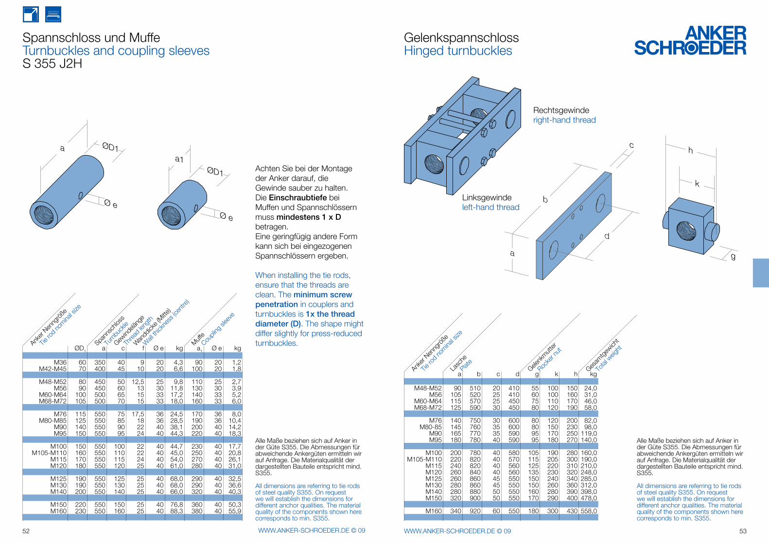
Spannschloss und MuffeTurnbuckles and coupling sleevesS 355 J2H
Achten Sie bei der Montage der Anker darauf, die Gewinde sauber zu halten.Die Einschraubtiefe bei Muffen und Spannschlössern muss mindestens 1 x D betragen.Eine geringfügig andere Form kann sich bei eingezogenen Spannschlössern ergeben.
When installing the tie rods, ensure that the threads are clean. The minimum screw penetration in couplers and turnbuckles is 1x the thread diameter (D). The shape might differ slightly for press-reduced turnbuckles.
GelenkspannschlossHinged turnbuckles
Rechtsgewinderight-hand thread
Linksgewindeleft-hand thread
Alle Maße beziehen sich auf Anker in der Güte S355. Die Abmessungen für abweichende Ankergüten ermitteln wir auf Anfrage. Die Materialqualität der dargestellten Bauteile entspricht mind. S355.
All dimensions are referring to tie rods of steel quality S355. On request we will establish the dimensions for different anchor qualities. The material quality of the components shown here corresponds to min. S355.
ØD1 a c f Ø e kg a1 Ø e kg
M36 60 350 40 9 20 4,3 90 20 1,2 M42-M45 70 400 45 10 20 6,6 100 20 1,8
M48-M52 80 450 50 12,5 25 9,8 110 25 2,7 M56 90 450 60 13 30 11,8 130 30 3,9 M60-M64 100 500 65 15 33 17,2 140 33 5,2 M68-M72 105 500 70 15 33 18,0 160 33 6,0
M76 115 550 75 17,5 36 24,5 170 36 8,0 M80-M85 125 550 85 18 36 28,5 190 36 10,4 M90 140 550 90 22 40 38,1 200 40 14,2 M95 150 550 95 24 40 44,3 220 40 18,3
M100 150 550 100 22 40 44,7 230 40 17,7 M105-M110 160 550 110 22 40 45,0 250 40 20,8 M115 170 550 115 24 40 54,0 270 40 26,1 M120 180 550 120 25 40 61,0 280 40 31,0
M125 190 550 125 25 40 68,0 290 40 32,5 M130 190 550 130 25 40 68,0 290 40 36,6 M140 200 550 140 25 40 66,0 320 40 40,3
M150 220 550 150 25 40 76,8 360 40 50,3 M160 230 550 160 25 40 88,3 380 40 55,9
a b c d g k h kg
M48-M52 90 510 20 410 55 100 150 24,0 M56 105 520 25 410 60 100 160 31,0 M60-M64 115 570 25 450 75 110 170 46,0 M68-M72 125 590 30 450 80 120 190 58,0
M76 140 750 30 600 80 120 200 82,0 M80-85 145 760 35 600 80 150 230 98,0 M90 165 770 35 590 95 170 250 119,0 M95 180 780 40 590 95 180 270 140,0
M100 200 780 40 580 105 190 280 160,0 M105-M110 220 820 40 570 115 205 300 190,0 M115 240 820 40 560 125 220 310 210,0 M120 260 840 40 560 135 230 320 248,0 M125 260 860 45 550 150 240 340 285,0 M130 280 860 45 550 150 260 360 312,0 M140 280 880 50 550 160 280 390 398,0 M150 320 900 50 550 170 290 400 478,0
M160 340 920 60 550 180 300 430 558,0
Anker
Nenng
röße
Tie ro
d no
minal s
ize
Spann
schlo
ss
Muffe
Turn
buck
le
Coupli
ng sl
eeve
Gewind
eläng
e
Threa
d len
gth
Wandd
icke (M
itte)
Wall
thick
ness
(cen
tre)
Tie ro
d no
minal s
ize
Anker
Nenng
röße
Plate
Lasc
he
Rocke
r nut
Gelenk
mutter
Total
weig
ht
Gesam
tgew
icht
ød1
g
c1
ød2
l1
l2
h1
54 WWW.ANKER-SCHROEDER.DE © 09 55WWW.ANKER-SCHROEDER.DE © 09
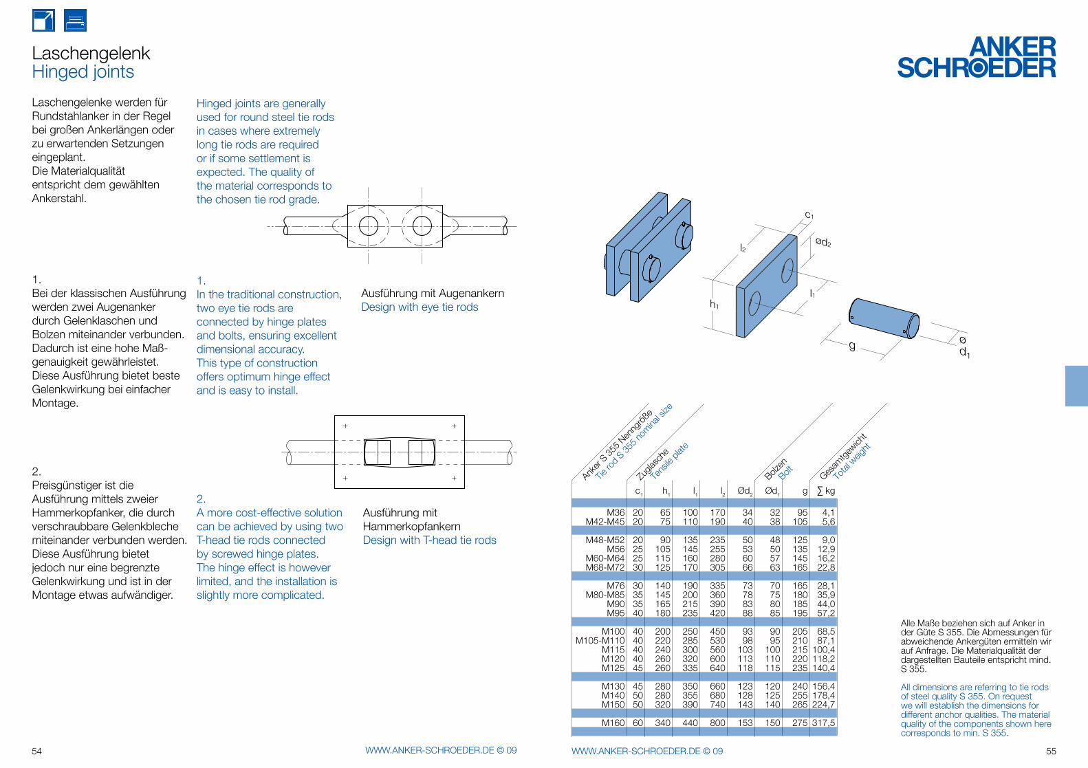
LaschengelenkHinged joints
Hinged joints are generally used for round steel tie rods in cases where extremely long tie rods are required or if some settlement is expected. The quality of the material corresponds to the chosen tie rod grade.
1.In the traditional construction, two eye tie rods are connected by hinge plates and bolts, ensuring excellent dimensional accuracy. This type of construction offers optimum hinge effect and is easy to install.
2.A more cost-effective solution can be achieved by using two T-head tie rods connected by screwed hinge plates. The hinge effect is however limited, and the installation is slightly more complicated.
Laschengelenke werden für Rundstahlanker in der Regel bei großen Anker längen oder zu erwartenden Setzungen eingeplant.Die Materialqualität entspricht dem gewählten Ankerstahl.
1.Bei der klassischen Ausführung werden zwei Augenanker durch Gelenklaschen und Bolzen miteinander verbunden.Dadurch ist eine hohe Maß-genauigkeit gewährleistet. Diese Aus führung bietet beste Gelenkwirkung bei einfacher Montage.
2.Preisgünstiger ist die Ausführung mittels zweier Hammerkopfanker, die durch verschraubbare Gelenkbleche miteinander verbunden werden. Diese Aus führung bietet jedoch nur eine begrenzte Gelenkwirkung und ist in der Mon tage etwas aufwändiger.
Ausführung mit AugenankernDesign with eye tie rods
Ausführung mit HammerkopfankernDesign with T-head tie rods
Alle Maße beziehen sich auf Anker in der Güte S 355. Die Abmessungen für abweichende Ankergüten ermitteln wir auf Anfrage. Die Materialqualität der dargestellten Bauteile entspricht mind. S 355.
All dimensions are referring to tie rods of steel quality S 355. On request we will establish the dimensions for different anchor qualities. The material quality of the components shown here corresponds to min. S 355.
c1 h1 l1 l2 Ød2 Ød1 g ∑ kg
M36 20 65 100 170 34 32 95 4,1 M42-M45 20 75 110 190 40 38 105 5,6
M48-M52 20 90 135 235 50 48 125 9,0 M56 25 105 145 255 53 50 135 12,9 M60-M64 25 115 160 280 60 57 145 16,2 M68-M72 30 125 170 305 66 63 165 22,8
M76 30 140 190 335 73 70 165 28,1 M80-M85 35 145 200 360 78 75 180 35,9 M90 35 165 215 390 83 80 185 44,0 M95 40 180 235 420 88 85 195 57,2
M100 40 200 250 450 93 90 205 68,5 M105-M110 40 220 285 530 98 95 210 87,1 M115 40 240 300 560 103 100 215 100,4 M120 40 260 320 600 113 110 220 118,2 M125 45 260 335 640 118 115 235 140,4
M130 45 280 350 660 123 120 240 156,4 M140 50 280 355 680 128 125 255 178,4 M150 50 320 390 740 143 140 265 224,7
M160 60 340 440 800 153 150 275 317,5
Anker
S 355 N
enng
röße
Tie ro
d S 35
5 nom
inal s
ize
Bolzen
Bolt Gesam
tgew
icht
Total
weig
ht
Zugla
sche
Tens
ile p
late
h
ød
ce
l
l
l3
2
2
1
ød1
g ød1g1
ød3
g3
c1
h
e
ød1
ød2
ød3
l4
a2
ød1g2
h
e
ød1
ød2
ød3
l5
a2
l3
ød4
a2
h
56 WWW.ANKER-SCHROEDER.DE © 09 57WWW.ANKER-SCHROEDER.DE © 09
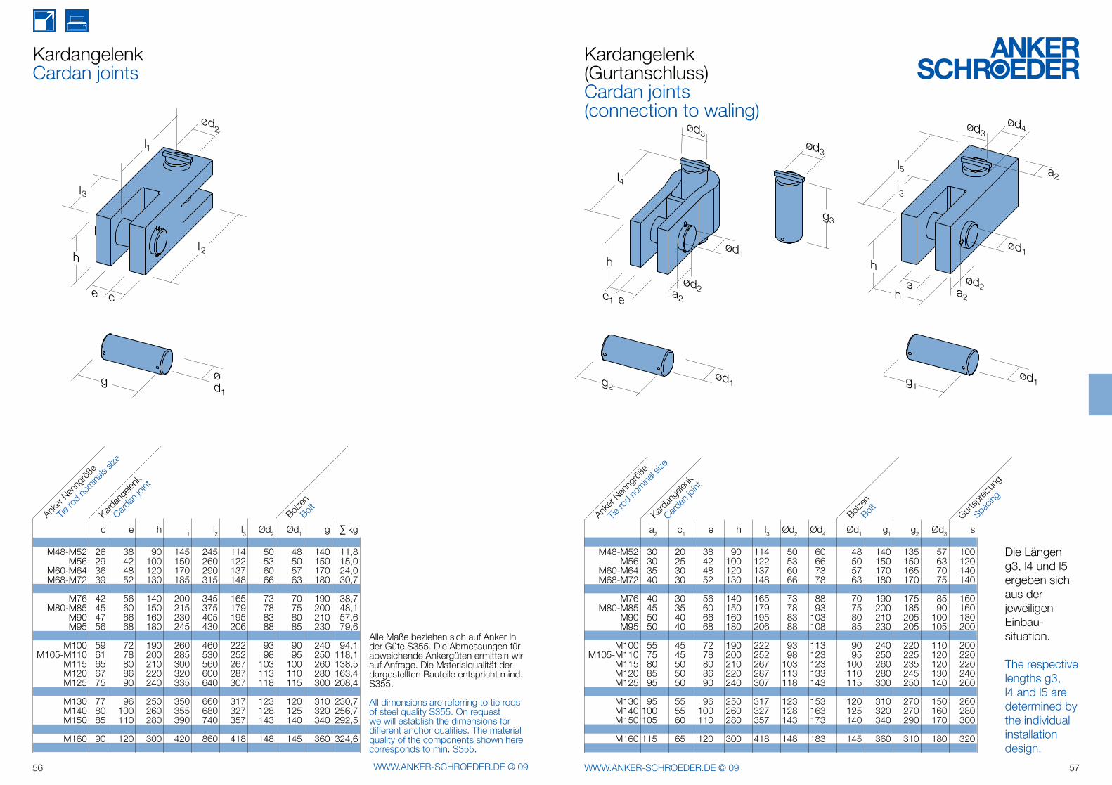
KardangelenkCardan joints
Kardangelenk(Gurtanschluss)Cardan joints(connection to waling)
Die Längen g3, l4 und l5 ergeben sich aus der jeweiligen Einbau-situation.
The respective lengths g3, l4 and l5 are determined by the individual installation design.
Alle Maße beziehen sich auf Anker in der Güte S355. Die Abmessungen für abweichende Ankergüten ermitteln wir auf Anfrage. Die Materialqualität der dargestellten Bauteile entspricht mind. S355.
All dimensions are referring to tie rods of steel quality S355. On request we will establish the dimensions for different anchor qualities. The material quality of the components shown here corresponds to min. S355.
c e h l1 l2 l3 Ød2 Ød1 g ∑ kg
M48-M52 26 38 90 145 245 114 50 48 140 11,8 M56 29 42 100 150 260 122 53 50 150 15,0 M60-M64 36 48 120 170 290 137 60 57 170 24,0 M68-M72 39 52 130 185 315 148 66 63 180 30,7
M76 42 56 140 200 345 165 73 70 190 38,7 M80-M85 45 60 150 215 375 179 78 75 200 48,1 M90 47 66 160 230 405 195 83 80 210 57,6 M95 56 68 180 245 430 206 88 85 230 79,6
M100 59 72 190 260 460 222 93 90 240 94,1 M105-M110 61 78 200 285 530 252 98 95 250 118,1 M115 65 80 210 300 560 267 103 100 260 138,5 M120 67 86 220 320 600 287 113 110 280 163,4 M125 75 90 240 335 640 307 118 115 300 208,4
M130 77 96 250 350 660 317 123 120 310 230,7 M140 80 100 260 355 680 327 128 125 320 256,7 M150 85 110 280 390 740 357 143 140 340 292,5
M160 90 120 300 420 860 418 148 145 360 324,6
a2 c1 e h l3 Ød2 Ød4 Ød1 g1 g2 Ød3 s
M48-M52 30 20 38 90 114 50 60 48 140 135 57 100 M56 30 25 42 100 122 53 66 50 150 150 63 120 M60-M64 35 30 48 120 137 60 73 57 170 165 70 140 M68-M72 40 30 52 130 148 66 78 63 180 170 75 140
M76 40 30 56 140 165 73 88 70 190 175 85 160 M80-M85 45 35 60 150 179 78 93 75 200 185 90 160 M90 50 40 66 160 195 83 103 80 210 205 100 180 M95 50 40 68 180 206 88 108 85 230 205 105 200
M100 55 45 72 190 222 93 113 90 240 220 110 200 M105-M110 75 45 78 200 252 98 123 95 250 225 120 220 M115 80 50 80 210 267 103 123 100 260 235 120 220 M120 85 50 86 220 287 113 133 110 280 245 130 240 M125 95 50 90 240 307 118 143 115 300 250 140 260
M130 95 55 96 250 317 123 153 120 310 270 150 260 M140 100 55 100 260 327 128 163 125 320 270 160 280 M150 105 60 110 280 357 143 173 140 340 290 170 300
M160 115 65 120 300 418 148 183 145 360 310 180 320
Tie ro
d no
minals
size
Anker
Nenng
röße
Kardan
gelen
k
Bolzen
Cardan
joint
BoltTie
rod
nomina
l size
Anker
Nenng
röße
Kardan
gelen
k
Bolzen
Cardan
joint
Bolt Gurtsp
reizu
ng
Spacin
g
58 WWW.ANKER-SCHROEDER.DE © 09 59WWW.ANKER-SCHROEDER.DE © 09
t
b
h
Ø
t
b
h
Ø
t
b
h
Ø
t
b
h
Ø
60 WWW.ANKER-SCHROEDER.DE © 09 61WWW.ANKER-SCHROEDER.DE © 09
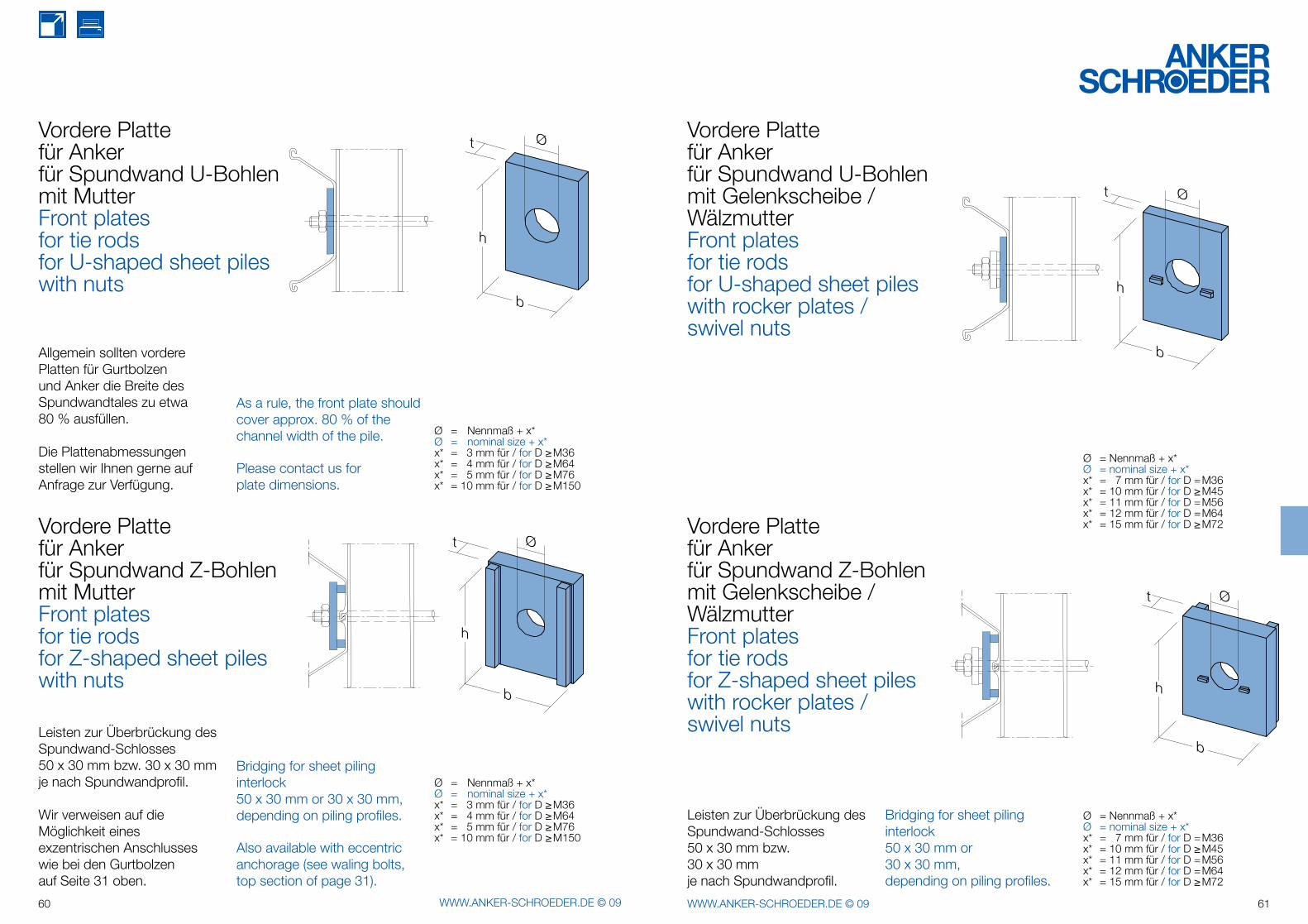
Vordere Plattefür Ankerfür Spundwand U-Bohlenmit MutterFront platesfor tie rodsfor U-shaped sheet pileswith nuts
Vordere Plattefür Ankerfür Spundwand Z-Bohlenmit MutterFront platesfor tie rodsfor Z-shaped sheet pileswith nuts
Ø = Nennmaß + x*Ø = nominal size + x*x* = 3 mm für / for D ≥ M36x* = 4 mm für / for D ≥ M64x* = 5 mm für / for D ≥ M76 x* = 10 mm für / for D ≥ M150
Allgemein sollten vordere Platten für Gurtbolzen und Anker die Breite des Spundwandtales zu etwa 80 % ausfüllen.
Die Plattenabmessungen stellen wir Ihnen gerne auf Anfrage zur Verfügung.
As a rule, the front plate should cover approx. 80 % of the channel width of the pile.
Please contact us for plate dimensions.
Ø = Nennmaß + x*Ø = nominal size + x*x* = 3 mm für / for D ≥ M36x* = 4 mm für / for D ≥ M64x* = 5 mm für / for D ≥ M76x* = 10 mm für / for D ≥ M150
Leisten zur Überbrückung des Spundwand-Schlosses50 x 30 mm bzw. 30 x 30 mm je nach Spundwandprofil.
Wir verweisen auf die Möglichkeit eines exzentrischen Anschlusses wie bei den Gurtbolzen auf Seite 31 oben.
Bridging for sheet pilinginterlock50 x 30 mm or 30 x 30 mm,depending on piling profiles.
Also available with eccentric anchorage (see waling bolts, top section of page 31).
Vordere Plattefür Ankerfür Spundwand U-Bohlenmit Gelenkscheibe / WälzmutterFront platesfor tie rodsfor U-shaped sheet pileswith rocker plates /swivel nuts
Vordere Plattefür Ankerfür Spundwand Z-Bohlenmit Gelenkscheibe / WälzmutterFront platesfor tie rodsfor Z-shaped sheet pileswith rocker plates /swivel nuts
Ø = Nennmaß + x*Ø = nominal size + x*x* = 7 mm für / for D = M36x* = 10 mm für / for D ≥ M45x* = 11 mm für / for D = M56x* = 12 mm für / for D = M64x* = 15 mm für / for D ≥ M72
Ø = Nennmaß + x*Ø = nominal size + x*x* = 7 mm für / for D = M36x* = 10 mm für / for D ≥ M45x* = 11 mm für / for D = M56x* = 12 mm für / for D = M64x* = 15 mm für / for D ≥ M72
Leisten zur Überbrückung des Spundwand-Schlosses50 x 30 mm bzw.30 x 30 mmje nach Spundwandprofil.
Bridging for sheet pilinginterlock50 x 30 mm or30 x 30 mm,depending on piling profiles.
62 WWW.ANKER-SCHROEDER.DE © 09 63WWW.ANKER-SCHROEDER.DE © 09
t
b
h
Ø
t
b
h
Ø
64 WWW.ANKER-SCHROEDER.DE © 09 65WWW.ANKER-SCHROEDER.DE © 09
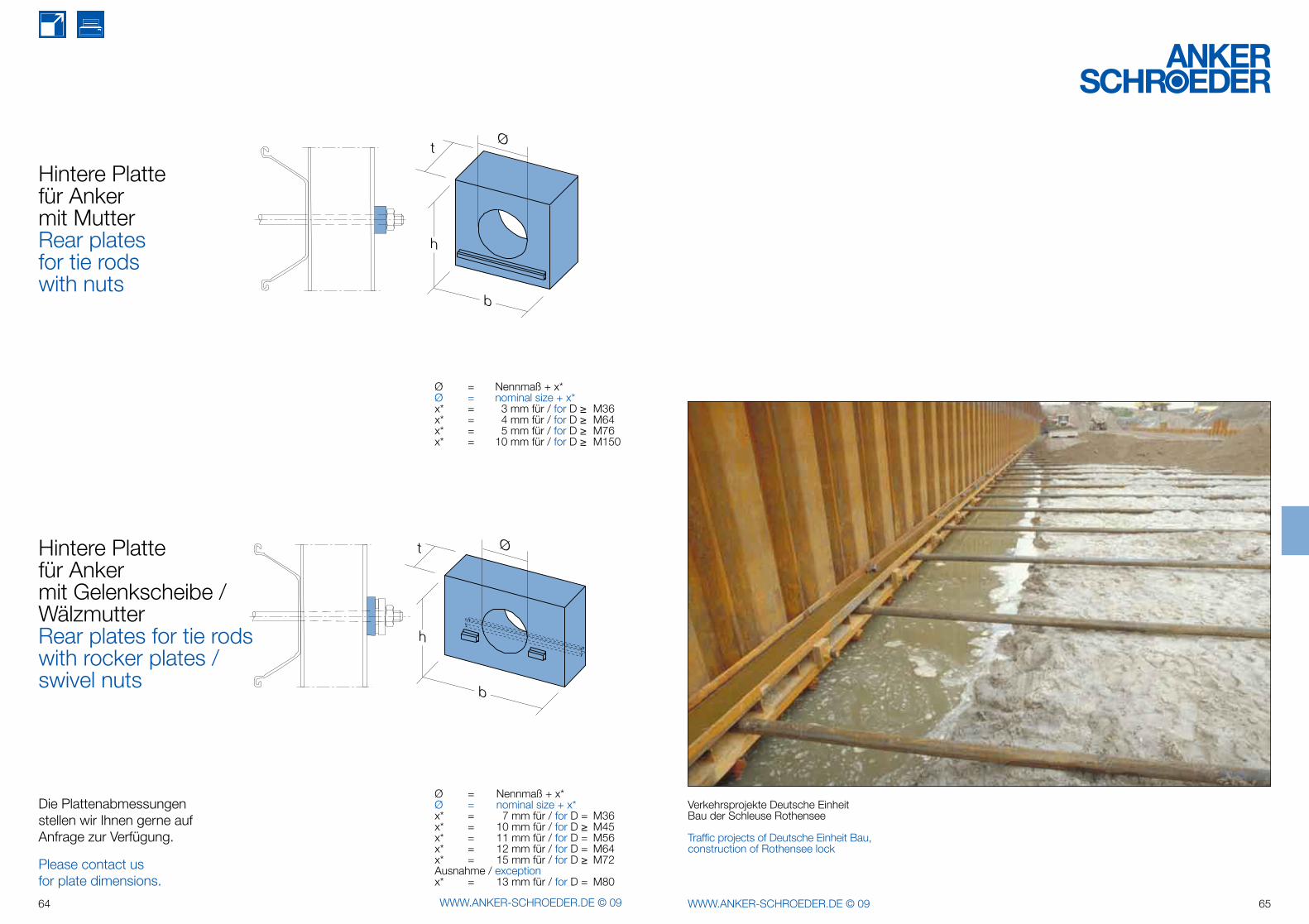
Ø = Nennmaß + x*Ø = nominal size + x*x* = 3 mm für / for D ≥ M36x* = 4 mm für / for D ≥ M64x* = 5 mm für / for D ≥ M76x* = 10 mm für / for D ≥ M150
Hintere Plattefür Ankermit Gelenkscheibe / WälzmutterRear plates for tie rodswith rocker plates /swivel nuts
Ø = Nennmaß + x*Ø = nominal size + x*x* = 7 mm für / for D = M36x* = 10 mm für / for D ≥ M45x* = 11 mm für / for D = M56x* = 12 mm für / for D = M64x* = 15 mm für / for D ≥ M72Ausnahme / exceptionx* = 13 mm für / for D = M80
Die Plattenabmessungen stellen wir Ihnen gerne auf Anfrage zur Verfügung.
Please contact us for plate dimensions.
Hintere Plattefür Ankermit MutterRear platesfor tie rodswith nuts
Verkehrsprojekte Deutsche EinheitBau der Schleuse Rothensee
Traffic projects of Deutsche Einheit Bau,construction of Rothensee lock
66 WWW.ANKER-SCHROEDER.DE © 09 67WWW.ANKER-SCHROEDER.DE © 09
68 WWW.ANKER-SCHROEDER.DE © 09 69WWW.ANKER-SCHROEDER.DE © 09
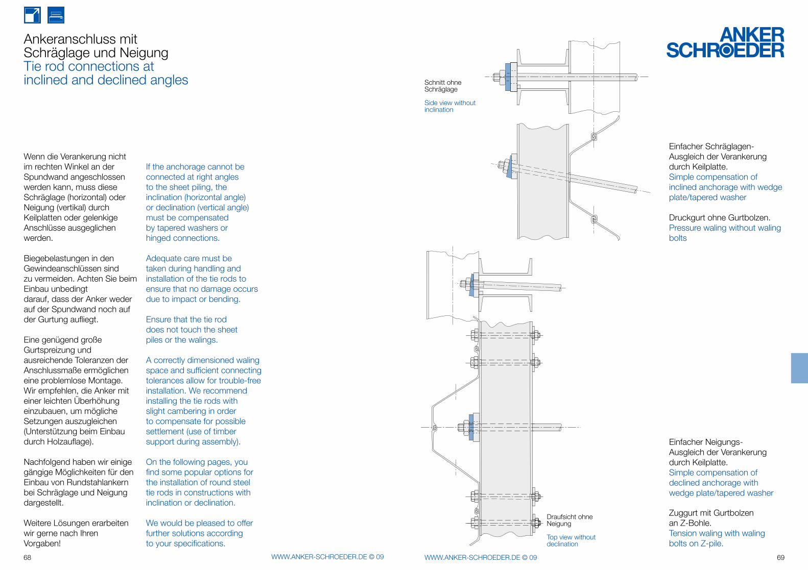
Ankeranschluss mitSchräglage und NeigungTie rod connections at inclined and declined angles
Wenn die Verankerung nicht im rechten Winkel an der Spundwand angeschlossen werden kann, muss diese Schräglage (horizontal) oder Neigung (vertikal) durch Keilplatten oder gelenkige Anschlüsse ausgeglichen werden.
Biegebelastungen in den Gewindeanschlüssen sind zu vermeiden. Achten Sie beim Einbau unbedingt darauf, dass der Anker weder auf der Spundwand noch auf der Gurtung aufliegt.
Eine genügend große Gurtspreizung und ausreichende Toleranzen der Anschlussmaße ermöglichen eine problemlose Montage. Wir empfehlen, die Anker mit einer leichten Überhöhung einzubauen, um mögliche Setzungen auszugleichen(Unterstützung beim Einbau durch Holzauflage).
Nachfolgend haben wir einige gängige Möglichkeiten für den Einbau von Rundstahlankern bei Schräglage und Neigung dargestellt.
Weitere Lösungen erarbeiten wir gerne nach Ihren Vorgaben!
If the anchorage cannot be connected at right angles to the sheet piling, the inclination (horizontal angle) or declination (vertical angle) must be compensated by tapered washers or hinged connections.
Adequate care must be taken during handling and installation of the tie rods to ensure that no damage occurs due to impact or bending.
Ensure that the tie rod does not touch the sheet piles or the walings.
A correctly dimensioned waling space and sufficient connecting tolerances allow for trouble-free installation. We recommend installing the tie rods with slight cambering in order to compensate for possible settlement (use of timber support during assembly).
On the following pages, you find some popular options for the installation of round steel tie rods in constructions with inclination or declination.
We would be pleased to offer further solutions according to your specifications.
Einfacher Neigungs-Ausgleich der Verankerung durch Keilplatte.Simple compensation of declined anchorage with wedge plate/tapered washer
Zuggurt mit Gurtbolzen an Z-Bohle.Tension waling with waling bolts on Z-pile.
Draufsicht ohne Neigung
Top view without declination
Einfacher Schräglagen-Ausgleich der Verankerung durch Keilplatte.Simple compensation of inclined anchorage with wedge plate/tapered washer
Druckgurt ohne Gurtbolzen.Pressure waling without waling bolts
Schnitt ohne Schräglage
Side view without inclination
70 WWW.ANKER-SCHROEDER.DE © 09 71WWW.ANKER-SCHROEDER.DE © 09
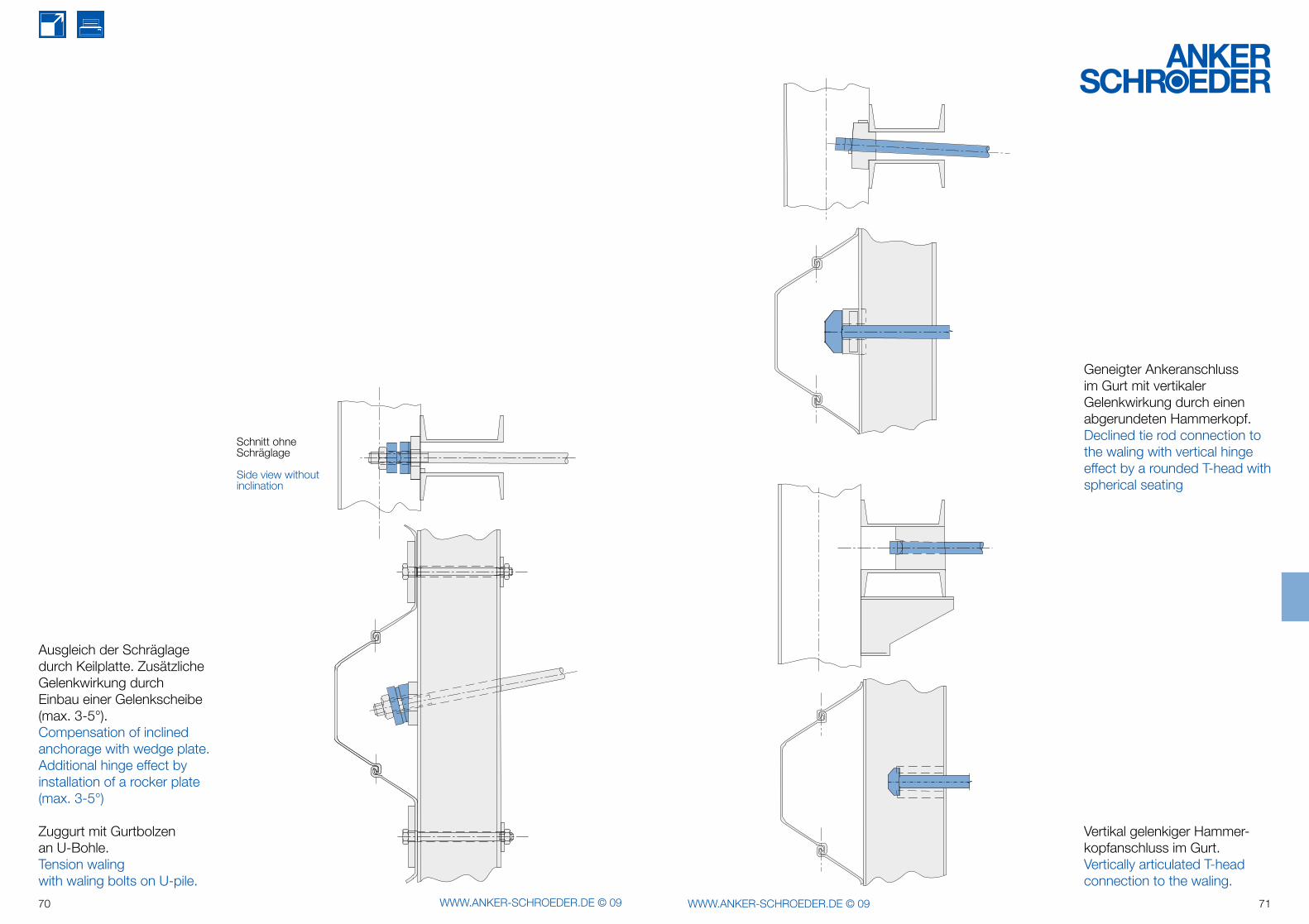
Ausgleich der Schräglage durch Keilplatte. Zusätzliche Gelenk wirkung durch Einbau einer Gelenk scheibe(max. 3-5°).Compensation of inclined anchorage with wedge plate. Additional hinge effect by installation of a rocker plate (max. 3-5°)
Zuggurt mit Gurtbolzen an U-Bohle.Tension waling with waling bolts on U-pile.
Schnitt ohne Schräglage
Side view without inclination
Geneigter Ankeranschluss im Gurt mit vertikaler Gelenkwirkung durch einen abgerundeten Hammerkopf.Declined tie rod connection to the waling with vertical hinge effect by a rounded T-head with spherical seating
Vertikal gelenkiger Hammer- kopfanschluss im Gurt.Vertically articulated T-head connection to the waling.
I.
II.
72 WWW.ANKER-SCHROEDER.DE © 09 73WWW.ANKER-SCHROEDER.DE © 09
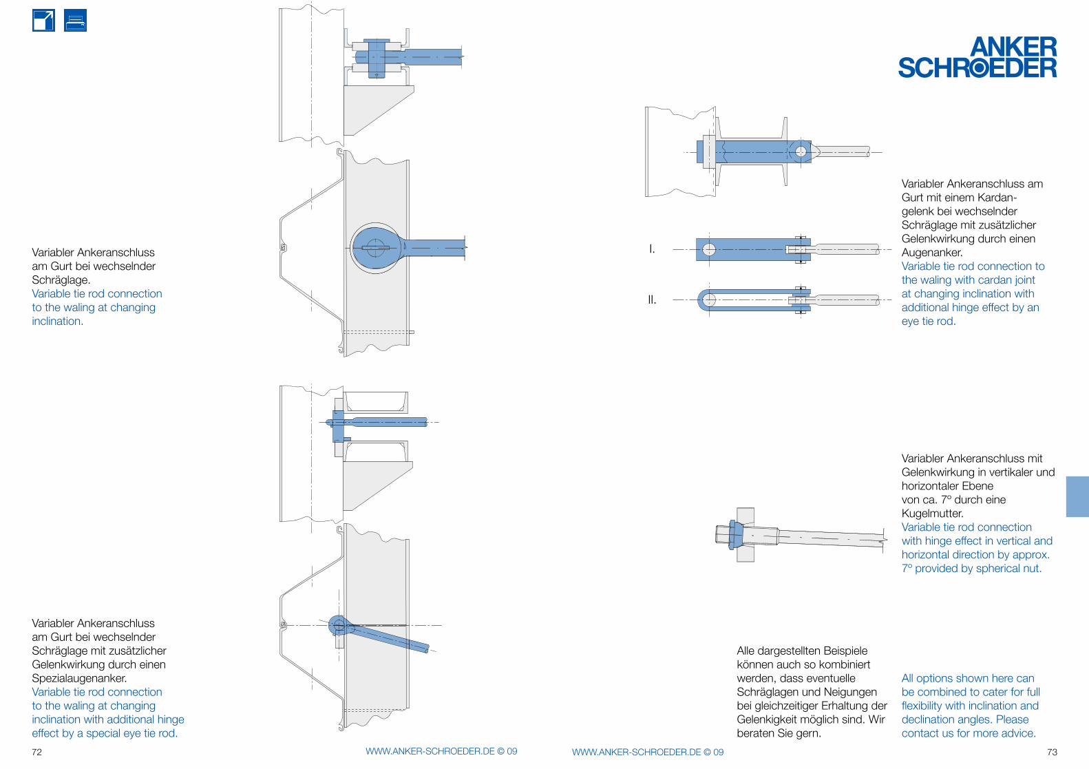
Variabler Ankeranschluss am Gurt bei wechselnder Schräglage.Variable tie rod connection to the waling at changing inclination.
Variabler Ankeranschluss am Gurt bei wechselnder Schräglage mit zusätzlicher Gelenkwirkung durch einen Spezialaugen anker.Variable tie rod connection to the waling at changing inclination with additional hinge effect by a special eye tie rod.
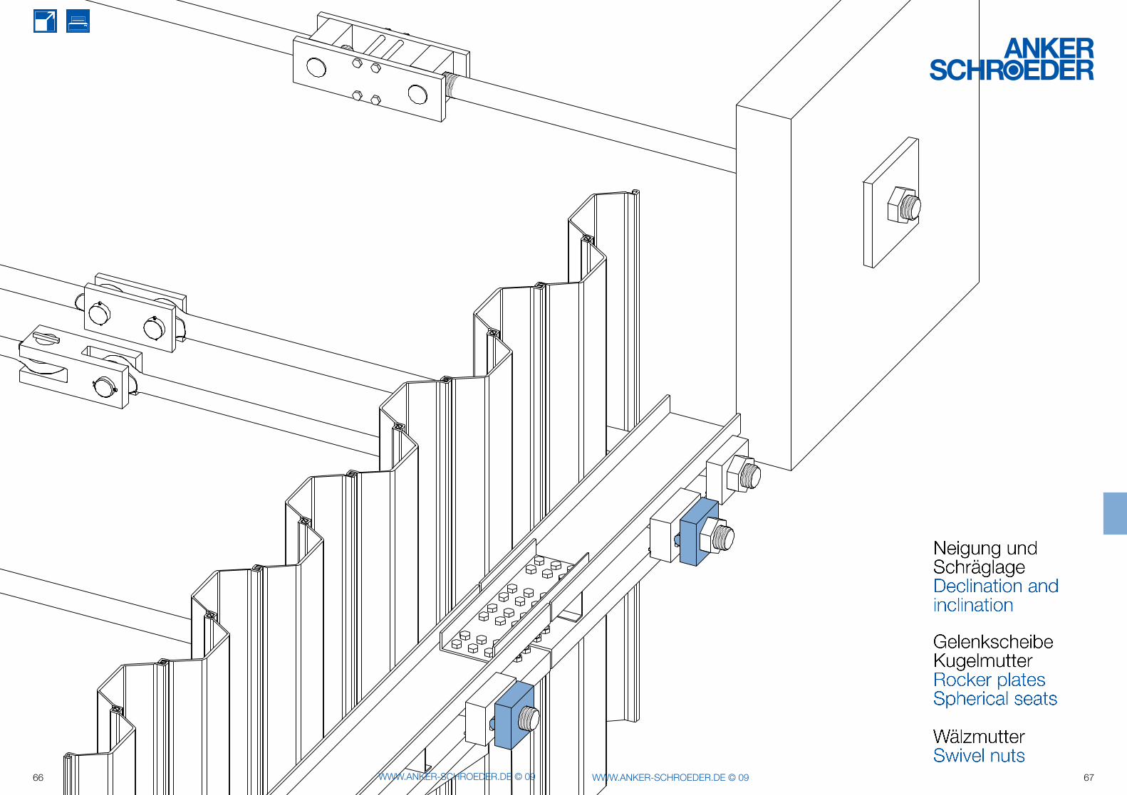
All options shown here can be combined to cater for full flexibility with inclination and declination angles. Please contact us for more advice.
Alle dargestellten Beispiele können auch so kombiniert werden, dass even tuelle Schräglagen und Neigungen bei gleichzeitiger Erhaltung der Gelen kigkeit möglich sind. Wir beraten Sie gern.
Variabler Ankeranschluss am Gurt mit einem Kardan-gelenk bei wechselnder Schräglage mit zusätzlicher Gelenk wirkung durch einen Augenanker.Variable tie rod connection to the waling with cardan joint at changing inclination with additional hinge effect by an eye tie rod.
Variabler Ankeranschluss mit Gelenkwirkung in vertikaler und hori zontaler Ebene von ca. 7º durch eine Kugelmutter.Variable tie rod connection with hinge effect in vertical and horizontal direction by approx. 7º provided by spherical nut.
t Ø
b
h50/60
t ØD
b
h50/60
74 WWW.ANKER-SCHROEDER.DE © 09 75WWW.ANKER-SCHROEDER.DE © 09
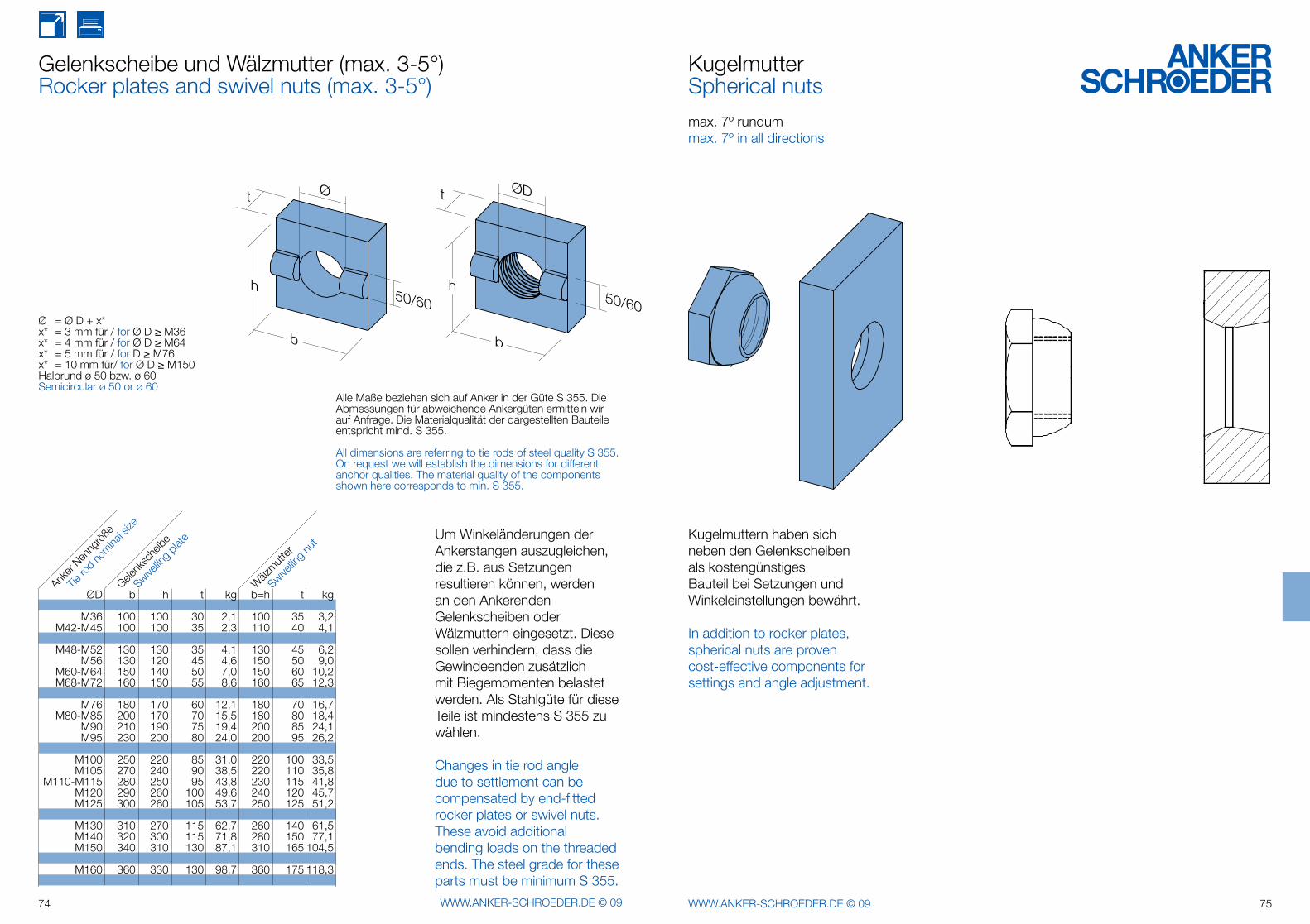
Gelenkscheibe und Wälzmutter (max. 3-5°)Rocker plates and swivel nuts (max. 3-5°)
Um Winkeländerungen der Ankerstangen auszugleichen, die z.B. aus Setzungen resultieren können, werden an den Ankerenden Gelenkscheiben oder Wälzmuttern eingesetzt. Diese sollen verhindern, dass die Gewindeenden zusätzlich mit Biegemomenten belastet werden. Als Stahlgüte für diese Teile ist mindestens S 355 zu wählen.
Changes in tie rod angledue to settlement can becompensated by end-fittedrocker plates or swivel nuts.These avoid additionalbending loads on the threadedends. The steel grade for theseparts must be minimum S 355.
Ø = Ø D + x*x* = 3 mm für / for Ø D ≥ M36x* = 4 mm für / for Ø D ≥ M64x* = 5 mm für / for D ≥ M76x* = 10 mm für/ for Ø D ≥ M150 Halbrund ø 50 bzw. ø 60Semicircular ø 50 or ø 60
KugelmutterSpherical nuts
max. 7º rundummax. 7º in all directions
Kugelmuttern haben sich neben den Gelenkscheiben als kostengünstiges Bauteil bei Setzungen und Winkeleinstellungen bewährt.
In addition to rocker plates, spherical nuts are proven cost-effective components for settings and angle adjustment.
Alle Maße beziehen sich auf Anker in der Güte S 355. Die Abmessungen für abweichende Ankergüten ermitteln wir auf Anfrage. Die Materialqualität der dargestellten Bauteile entspricht mind. S 355.
All dimensions are referring to tie rods of steel quality S 355. On request we will establish the dimensions for different anchor qualities. The material quality of the components shown here corresponds to min. S 355.
ØD b h t kg b=h t kg
M36 100 100 30 2,1 100 35 3,2 M42-M45 100 100 35 2,3 110 40 4,1
M48-M52 130 130 35 4,1 130 45 6,2 M56 130 120 45 4,6 150 50 9,0 M60-M64 150 140 50 7,0 150 60 10,2 M68-M72 160 150 55 8,6 160 65 12,3
M76 180 170 60 12,1 180 70 16,7 M80-M85 200 170 70 15,5 180 80 18,4 M90 210 190 75 19,4 200 85 24,1 M95 230 200 80 24,0 200 95 26,2
M100 250 220 85 31,0 220 100 33,5 M105 270 240 90 38,5 220 110 35,8 M110-M115 280 250 95 43,8 230 115 41,8 M120 290 260 100 49,6 240 120 45,7 M125 300 260 105 53,7 250 125 51,2
M130 310 270 115 62,7 260 140 61,5 M140 320 300 115 71,8 280 150 77,1 M150 340 310 130 87,1 310 165 104,5
M160 360 330 130 98,7 360 175 118,3
Tie ro
d no
minal s
ize
Anker
Nenng
röße
Swivellin
g plat
e
Gelenk
sche
ibe
Swivellin
g nut
Wälz
mutter
76 WWW.ANKER-SCHROEDER.DE © 09 77WWW.ANKER-SCHROEDER.DE © 09
b
l
l
t
t
a
b
ød
e2
1
1
1
2
2
78 WWW.ANKER-SCHROEDER.DE © 09 79WWW.ANKER-SCHROEDER.DE © 09
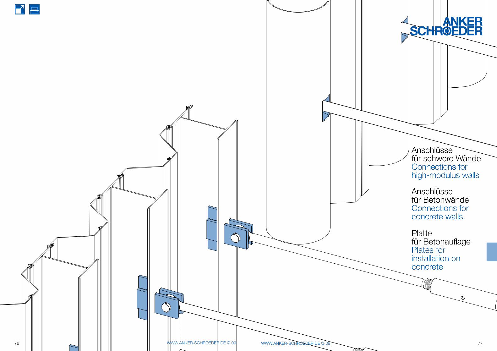
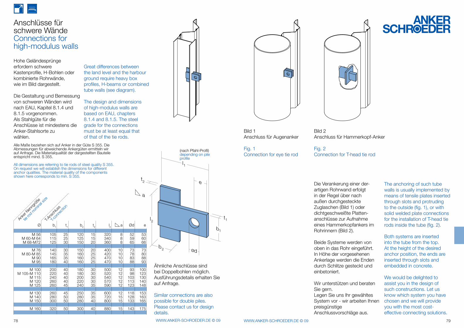
Anschlüsse für schwere WändeConnections for high-modulus walls
Hohe Geländesprünge erfordern schwere Kastenprofile, H-Bohlen oder kombi nierte Rohrwände,wie im Bild darge stellt.
Die Gestaltung und Bemessung von schweren Wänden wird nach EAU, Kapitel 8.1.4 und 8.1.5 vorgenommen.Als Stahlgüte für die Anschlüsse ist mindestens die Anker-Stahlsorte zu wählen.
Great differences between the land level and the harbour ground require heavy box profiles, H-beams or combined tube walls (see diagram).
The design and dimensions of high-modulus walls are based on EAU, chapters 8.1.4 and 8.1.5. The steel grade for the connections must be at least equal that of that of the tie rods.
Ähnliche Anschlüsse sind bei Doppelbohlen möglich. Ausführungsdetails erhalten Sie auf Anfrage.
Similar connections are alsopossible for double piles.Please contact us for designdetails.
(nach Pfahl-Profil)depending on pile profile
The anchoring of such tube walls is usually implemented by means of tensile plates inserted through slots and protruding to the outside (fig. 1), or with solid welded plate connections for the installation of T-head tie rods inside the tube (fig. 2).
Both systems are inserted into the tube from the top.At the height of the desired anchor position, the ends are inserted through slots and embedded in concrete.
We would be delighted to assist you in the design of such constructions. Let us know which system you have chosen and we will provide you with the most cost-effective connecting solutions.
Die Verankerung einer der-artigen Rohrwand erfolgt in der Regel über nach außen durchgesteckte Zuglaschen (Bild 1) oder dichtgeschweißte Plat ten-an schlüsse zur Aufnahme eines Hammer kopfankers im Rohrinnern (Bild 2).
Beide Systeme werden von oben in das Rohr eingeführt. In Höhe der vorge sehenen Ankerlage werden die Enden durch Schlitze gesteckt und einbe toniert.
Wir unterstützen und beraten Sie gern. Legen Sie uns Ihr gewähltes System vor - wir arbeiten Ihnen preisgünstige Anschlussvorschläge aus.
Bild 2Anschluss für Hammerkopf-Anker
Fig. 2 Connection for T-head tie rod
Bild 1Anschluss für Augenanker
Fig. 1Connection for eye tie rod
Alle Maße beziehen sich auf Anker in der Güte S 355. Die Abmessungen für abweichende Ankergüten ermitteln wir auf Anfrage. Die Materialqualität der dargestellten Bauteile entspricht mind. S 355.
All dimensions are referring to tie rods of steel quality S 355. On request we will establish the dimensions for different anchor qualities. The material quality of the components shown here corresponds to min. S 355.
Ø b1 t1 b2 t2 l2 a Ød e
M 56 105 25 120 15 320 8 52 53 M 60-M 64 115 25 125 15 340 8 59 60 M 68-M72 125 30 150 20 360 8 65 66
M 76 140 30 150 20 400 10 73 73 M 80-M 85 145 35 160 25 420 10 78 80 M 90 165 35 160 25 470 10 83 88 M 95 180 40 160 25 470 10 88 93
M 100 200 40 180 30 500 12 93 100 M 105-M 110 220 40 180 30 520 12 98 123 M 115 240 40 200 30 540 12 103 130 M 120 260 40 220 30 570 12 113 140 M 125 260 45 240 35 590 12 123 148
M 130 260 45 250 35 600 12 118 153 M 140 280 50 280 35 720 15 128 163 M 150 300 50 280 40 800 15 133 165
M 160 320 50 300 40 880 15 143 175
T-Ans
chlus
s
T-con
necti
on
tierod
nomina
l size
Anker
Nenng
röße
80 WWW.ANKER-SCHROEDER.DE © 09 81WWW.ANKER-SCHROEDER.DE © 09
Anschlüsse für BetonwändeConnections for concrete walls
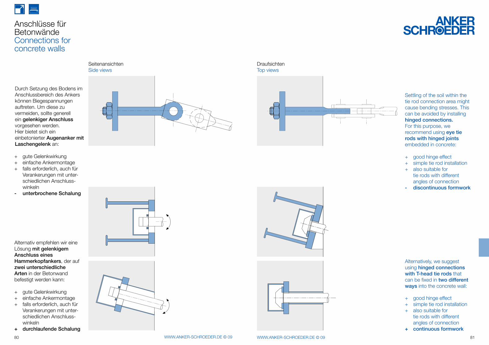
+ gute Gelenkwirkung+ einfache Ankermontage+ falls erforderlich, auch für Verankerungen mit unter- schiedlichen Anschluss- winkeln- unterbrochene Schalung
Alternativ empfehlen wir eine Lösung mit gelenkigem Anschluss eines Hammerkopfankers, der aufzwei unterschiedlicheArten in der Betonwand befestigt werden kann:
+ gute Gelenkwirkung+ einfache Ankermontage+ falls erforderlich, auch für Verankerungen mit unter- schiedlichen Anschluss- winkeln+ durchlaufende Schalung
SeitenansichtenSide views
Durch Setzung des Bodens im Anschlussbereich des Ankers können Biegespannungen auftreten. Um diese zu vermeiden, sollte generell ein gelenkiger Anschluss vorgesehen werden.Hier bietet sich eineinbetonierter Augenanker mit Laschengelenk an:
Settling of the soil within the tie rod connection area might cause bending stresses. This can be avoided by installing hinged connections.For this purpose, we recommend using eye tie rods with hinged jointsembedded in concrete:
+ good hinge effect+ simple tie rod installation+ also suitable for tie rods with different angles of connection- discontinuous formwork
Alternatively, we suggest using hinged connections with T-head tie rods that can be fixed in two different ways into the concrete wall:
+ good hinge effect+ simple tie rod installation+ also suitable for tie rods with different angles of connection+ continuous formwork
DraufsichtenTop views
t Ø
b
82 WWW.ANKER-SCHROEDER.DE © 09 83WWW.ANKER-SCHROEDER.DE © 09
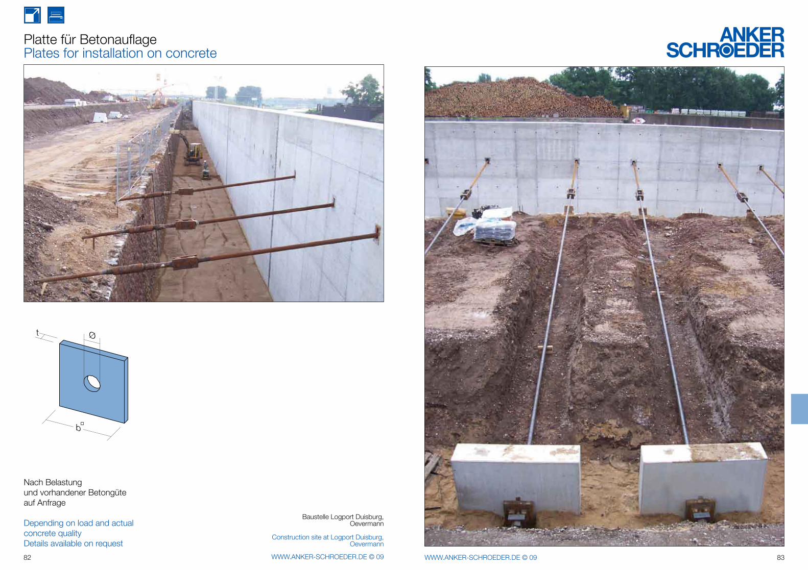
Platte für BetonauflagePlates for installation on concrete
Nach Belastungund vorhandener Betongüteauf Anfrage
Depending on load and actual concrete quality Details available on request
Baustelle Logport Duisburg,Oevermann
Construction site at Logport Duisburg,Oevermann
84 WWW.ANKER-SCHROEDER.DE © 09 85WWW.ANKER-SCHROEDER.DE © 09
a
b
aa
b
aa
b
86 WWW.ANKER-SCHROEDER.DE © 09 87WWW.ANKER-SCHROEDER.DE © 09
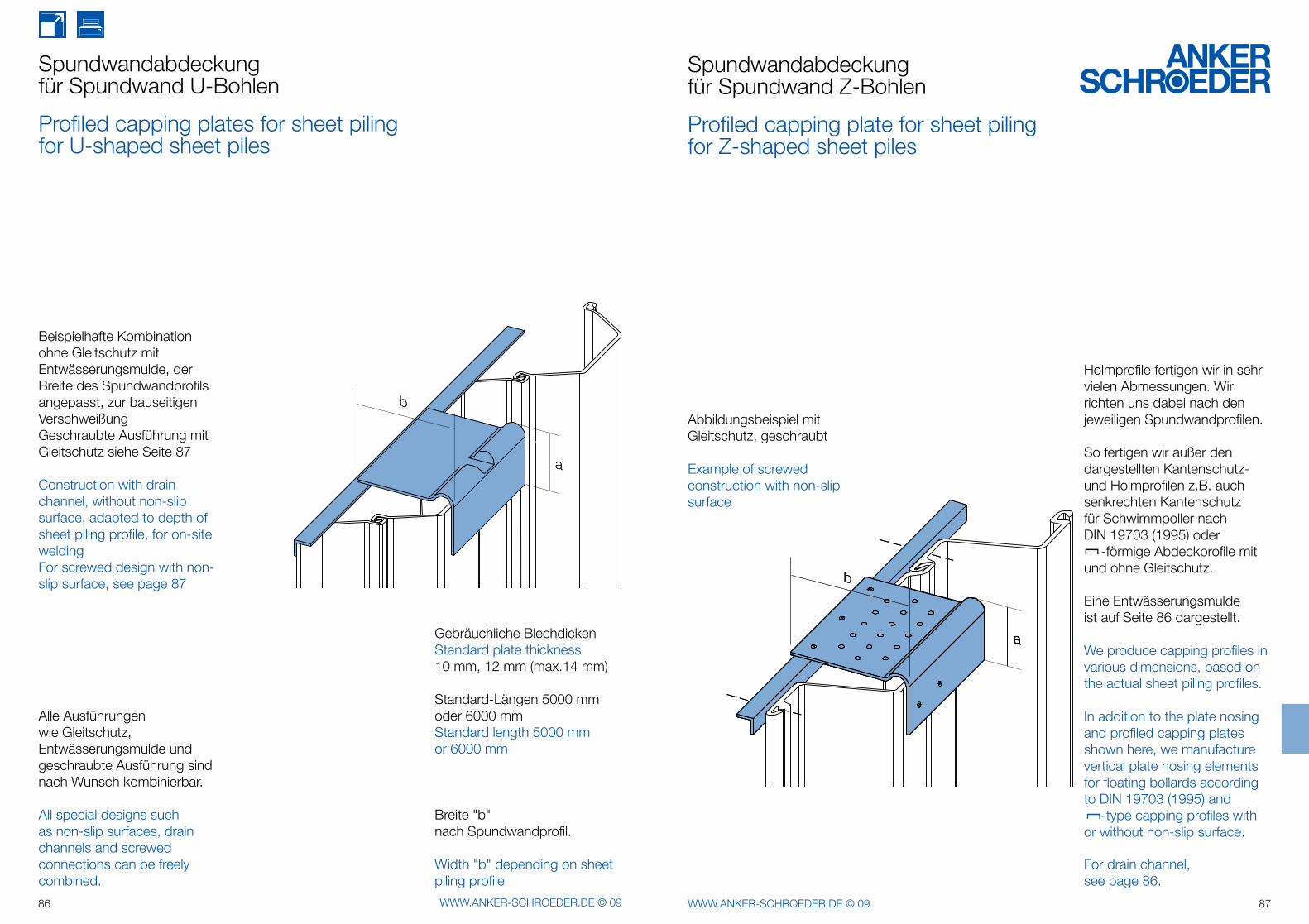
Gebräuchliche BlechdickenStandard plate thickness10 mm, 12 mm (max.14 mm)
Standard-Längen 5000 mm oder 6000 mmStandard length 5000 mmor 6000 mm
Beispielhafte Kombination ohne Gleitschutz mit Entwässerungsmulde, der Breite des Spundwandprofils angepasst, zur bauseitigen VerschweißungGeschraubte Ausführung mitGleitschutz siehe Seite 87
Construction with drain channel, without non-slip surface, adapted to depth of sheet piling profile, for on-site weldingFor screwed design with non-slip surface, see page 87
Alle Ausführungen wie Gleitschutz, Entwässerungsmulde und geschraubte Ausführung sind nach Wunsch kombinierbar.
All special designs such as non-slip surfaces, drain channels and screwed connections can be freely combined.
Breite "b" nach Spundwandprofil.
Width "b" depending on sheet piling profile
Spundwandabdeckungfür Spundwand U-Bohlen
Profiled capping plates for sheet pilingfor U-shaped sheet piles
Holmprofile fertigen wir in sehr vielen Abmessungen. Wir richten uns dabei nach den jeweiligen Spundwandprofilen.
So fertigen wir außer den dargestellten Kantenschutz- und Holmprofilen z.B. auch senkrechten Kantenschutz für Schwimmpoller nach DIN 19703 (1995) oder [
-förmige Abdeckprofile mit und ohne Gleitschutz.
Eine Entwässerungsmulde ist auf Seite 86 dargestellt.
We produce capping profiles in various dimensions, based on the actual sheet piling profiles.
In addition to the plate nosing and profiled capping plates shown here, we manufacture vertical plate nosing elements for floating bollards according to DIN 19703 (1995) and[
-type capping profiles with or without non-slip surface.
For drain channel, see page 86.
Spundwandabdeckungfür Spundwand Z-Bohlen
Profiled capping plate for sheet pilingfor Z-shaped sheet piles
Abbildungsbeispiel mit Gleitschutz, geschraubt
Example of screwed construction with non-slip surface
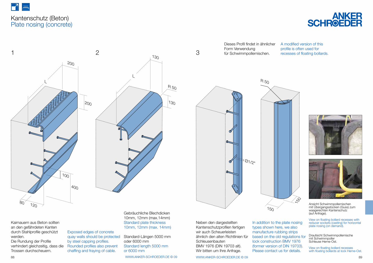
120
L
80
400
200
200
100
L
R 50
130
130
Ø1/2"
150
150
R 50
88 WWW.ANKER-SCHROEDER.DE © 09 89WWW.ANKER-SCHROEDER.DE © 09
Kantenschutz (Beton)Plate nosing (concrete)
1 2
Kaimauern aus Beton sollten an den gefährdeten Kanten durch Stahlprofile geschützt werden.Die Rundung der Profile verhindert gleichzeitig, dass die Trossen durchscheuern.
Exposed edges of concrete quay walls should be protected by steel capping profiles. Rounded profiles also prevent chaffing and fraying of cable.
Gebräuchliche Blechdicken10mm, 12mm (max.14mm)Standard plate thickness10mm, 12mm (max. 14mm)
Standard-Längen 5000 mm oder 6000 mmStandard length 5000 mmor 6000 mm
3
Neben den dargestellten Kantenschutzprofilen fertigen wir auch Scheuerleisten ähnlich den alten Richtlinien für Schleusenbauten BMV 1976 (DIN 19703 alt).Wir bitten um Ihre Anfrage.
Dieses Profil findet in ähnlicher Form Verwendungfür Schwimmpollernischen.
A modified version of this profile is often used for recesses of floating bollards.
In addition to the plate nosing types shown here, we also manufacture rubbing strips based on the old regulations for lock construction BMV 1976 (former version of DIN 19703). Please contact us for details.
Draufsicht Schwimmpollernische mit Schwimmpoller Schleuse Herne-Ost.
View on floating bollard recesses with floating bollards at lock Herne-Ost.
Ansicht Schwimmpollernischen mit Übergangsstücken (Guss) zum waagerechten Kantenschutz (auf Anfrage).
View on floating bollard recesses with reducer sockets (casting) for horizontal plate nosing (on demand).
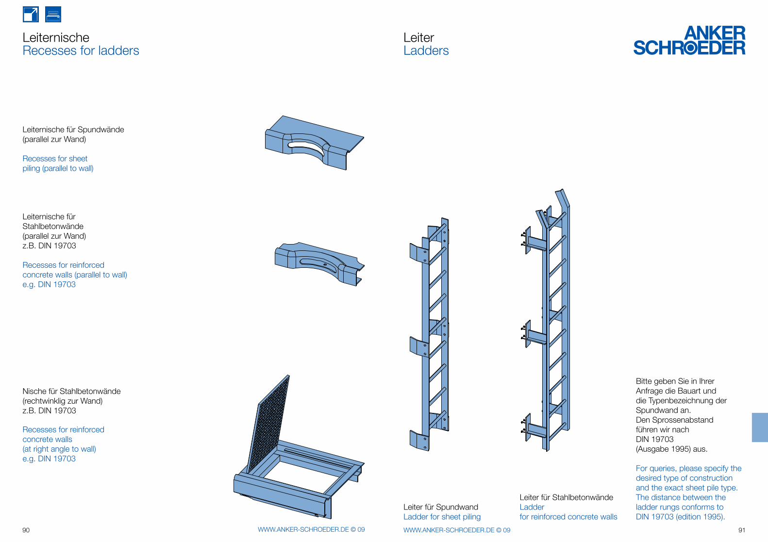
90 WWW.ANKER-SCHROEDER.DE © 09 91WWW.ANKER-SCHROEDER.DE © 09
Leiternische für Spundwände (parallel zur Wand)
Recesses for sheet piling (parallel to wall)
Leiternische für Stahlbetonwände(parallel zur Wand)z.B. DIN 19703
Recesses for reinforced concrete walls (parallel to wall)e.g. DIN 19703
Nische für Stahlbetonwände (rechtwinklig zur Wand)z.B. DIN 19703
Recesses for reinforced concrete walls (at right angle to wall)e.g. DIN 19703
LeiternischeRecesses for ladders
Leiter für StahlbetonwändeLadder for reinforced concrete walls
Leiter für SpundwandLadder for sheet piling
Bitte geben Sie in Ihrer Anfrage die Bauart und die Typenbezeichnung der Spundwand an. Den Sprossenabstandführen wir nachDIN 19703 (Ausgabe 1995) aus.
For queries, please specify the desired type of construction and the exact sheet pile type. The distance between the ladder rungs conforms toDIN 19703 (edition 1995).
LeiterLadders
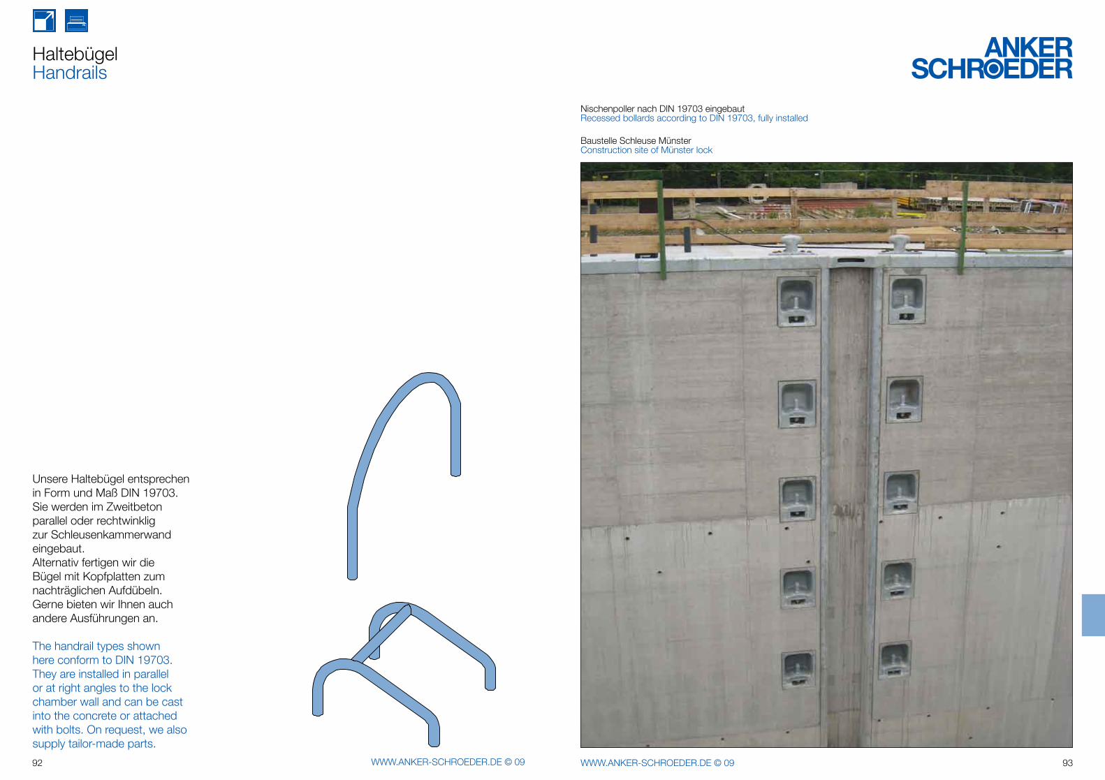
92 WWW.ANKER-SCHROEDER.DE © 09 93WWW.ANKER-SCHROEDER.DE © 09
Unsere Haltebügel entsprechen in Form und Maß DIN 19703. Sie werden im Zweitbeton parallel oder rechtwinklig zur Schleusenkammerwand eingebaut. Alternativ fertigen wir die Bügel mit Kopfplatten zum nachträglichen Aufdübeln.Gerne bieten wir Ihnen auch andere Ausführungen an.
The handrail types shown here conform to DIN 19703. They are installed in parallel or at right angles to the lock chamber wall and can be cast into the concrete or attached with bolts. On request, we also supply tailor-made parts.
HaltebügelHandrails
Nischenpoller nach DIN 19703 eingebaut Recessed bollards according to DIN 19703, fully installed
Baustelle Schleuse MünsterConstruction site of Münster lock
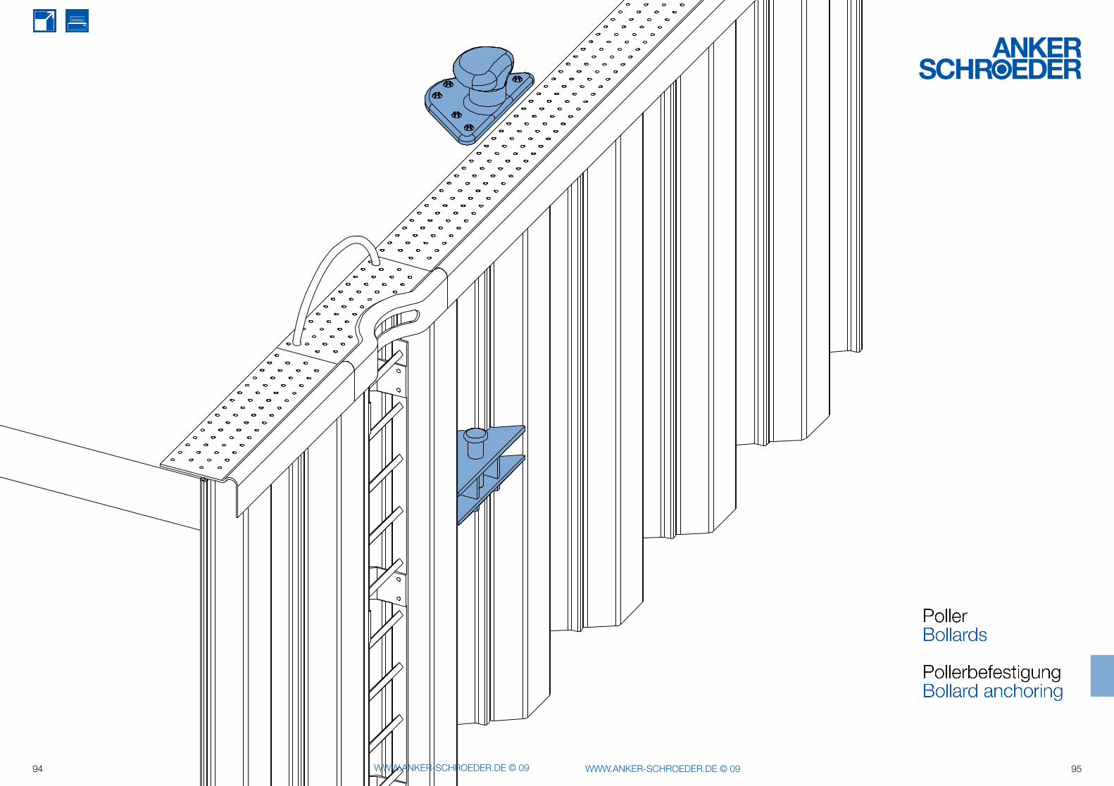
94 WWW.ANKER-SCHROEDER.DE © 09 95WWW.ANKER-SCHROEDER.DE © 09
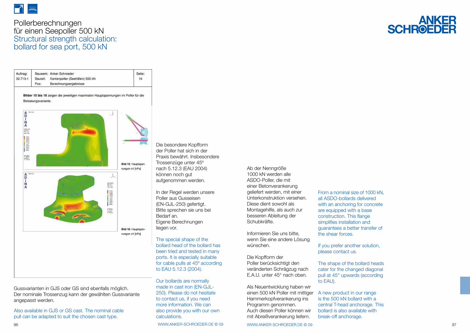
96 WWW.ANKER-SCHROEDER.DE © 09 97WWW.ANKER-SCHROEDER.DE © 09
Pollerberechnungenfür einen Seepoller 500 kNStructural strength calculation:bollard for sea port, 500 kN
Die besondere Kopfformder Poller hat sich in der Praxis bewährt. Insbesondere Trossenzüge unter 45ºnach 5.12.3 (EAU 2004) können noch gut aufgenommen werden.
In der Regel werden unsere Poller aus Gusseisen(EN-GJL-250) gefertigt.Bitte sprechen sie uns bei Bedarf an.Eigene Berechnungen liegen vor.
The special shape of the bollard head of the bollard has been tried and tested in many ports. It is especially suitable for cable pulls at 45º according to EAU 5.12.3 (2004).
Our bollards are normally made in cast iron (EN-GJL-250). Please do not hesitate to contact us, if you need more information. We can also provide you with our own calculations.
Also available in GJS or GS cast. The nominal cable pull can be adapted to suit the chosen cast type.
Ab der Nenngröße1000 kN werden alle ASDO-Poller, die mit einer Betonverankerung geliefert werden, mit einer Unterkonstruktion versehen.Diese dient sowohl als Montagehilfe, als auch zur besseren Ableitung der Schubkräfte.
Informieren Sie uns bitte, wenn Sie eine andere Lösung wünschen.
Die Kopfform derPoller berücksichtigt den veränderten Schrägzug nach E.A.U. unter 45° nach oben.
Als Neuentwicklung haben wir einen 500 kN Poller mit mittiger Hammerkopfverankerung ins Programm genommen.Auch diesen Poller können wir mit Abreißverankerung liefern.
From a nominal size of 1000 kN, all ASDO-bollards delivered with an anchoring for concrete are equipped with a base construction. This flange simplifies installation and guarantees a better transfer of the shear forces.
If you prefer another solution, please contact us.
The shape of the bollard heads cater for the changed diagonal pull at 45° upwards (according to EAU).
A new product in our range is the 500 kN bollard with a central T-head anchorage. This bollard is also available with break-off anchorage.
Gussvarianten in GJS oder GS sind ebenfalls möglich.Der nominale Trossenzug kann der gewählten Gussvariante angepasst werden.
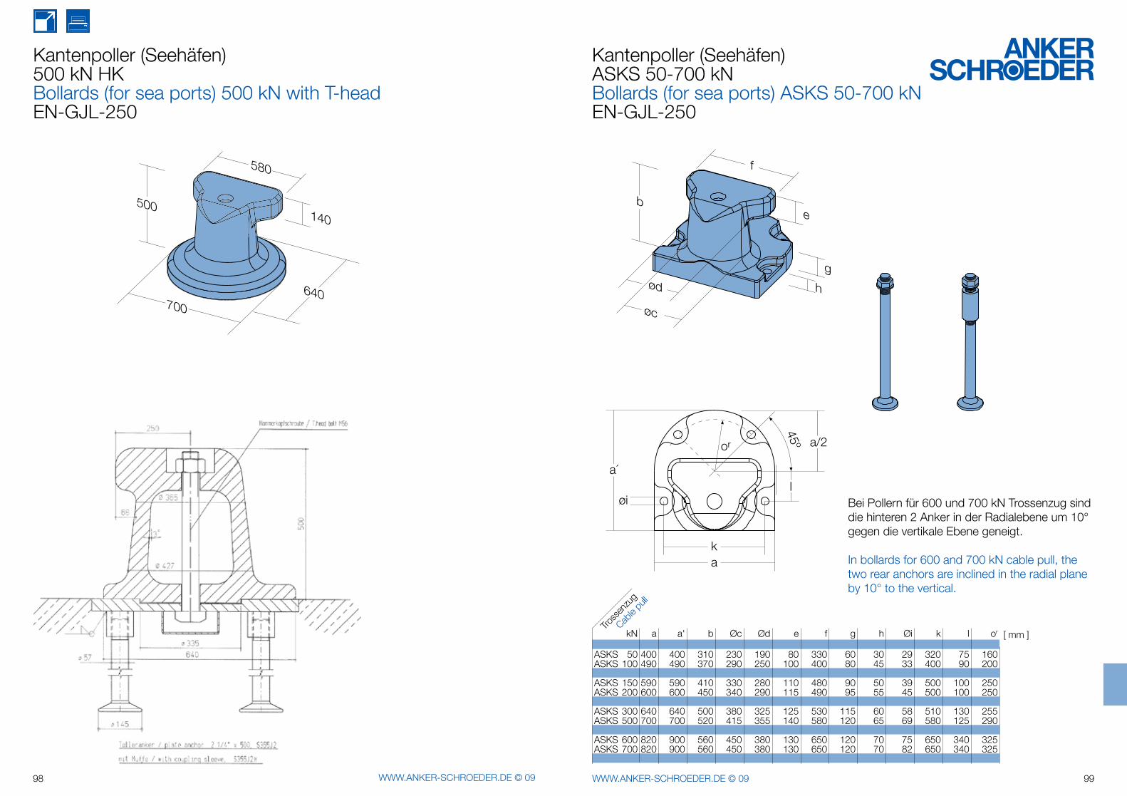
580
140500
700640
f
e
ød
øc
g
h
b
øil
ka
or
a´
45º a/2
98 WWW.ANKER-SCHROEDER.DE © 09 99WWW.ANKER-SCHROEDER.DE © 09
Kantenpoller (Seehäfen)500 kN HKBollards (for sea ports) 500 kN with T-headEN-GJL-250
Kantenpoller (Seehäfen)ASKS 50-700 kNBollards (for sea ports) ASKS 50-700 kNEN-GJL-250
Bei Pollern für 600 und 700 kN Trossenzug sind die hinteren 2 Anker in der Radialebene um 10° gegen die vertikale Ebene geneigt.
In bollards for 600 and 700 kN cable pull, the two rear anchors are inclined in the radial plane by 10° to the vertical.
Tross
enzu
g
Cable
pulll
kN a a' b Øc Ød e f g h Øi k l or
ASKS 50 400 400 310 230 190 80 330 60 30 29 320 75 160 ASKS 100 490 490 370 290 250 100 400 80 45 33 400 90 200
ASKS 150 590 590 410 330 280 110 480 90 50 39 500 100 250 ASKS 200 600 600 450 340 290 115 490 95 55 45 500 100 250
ASKS 300 640 640 500 380 325 125 530 115 60 58 510 130 255 ASKS 500 700 700 520 415 355 140 580 120 65 69 580 125 290
ASKS 600 820 900 560 450 380 130 650 120 70 75 650 340 325 ASKS 700 820 900 560 450 380 130 650 120 70 82 650 340 325
[ mm ]
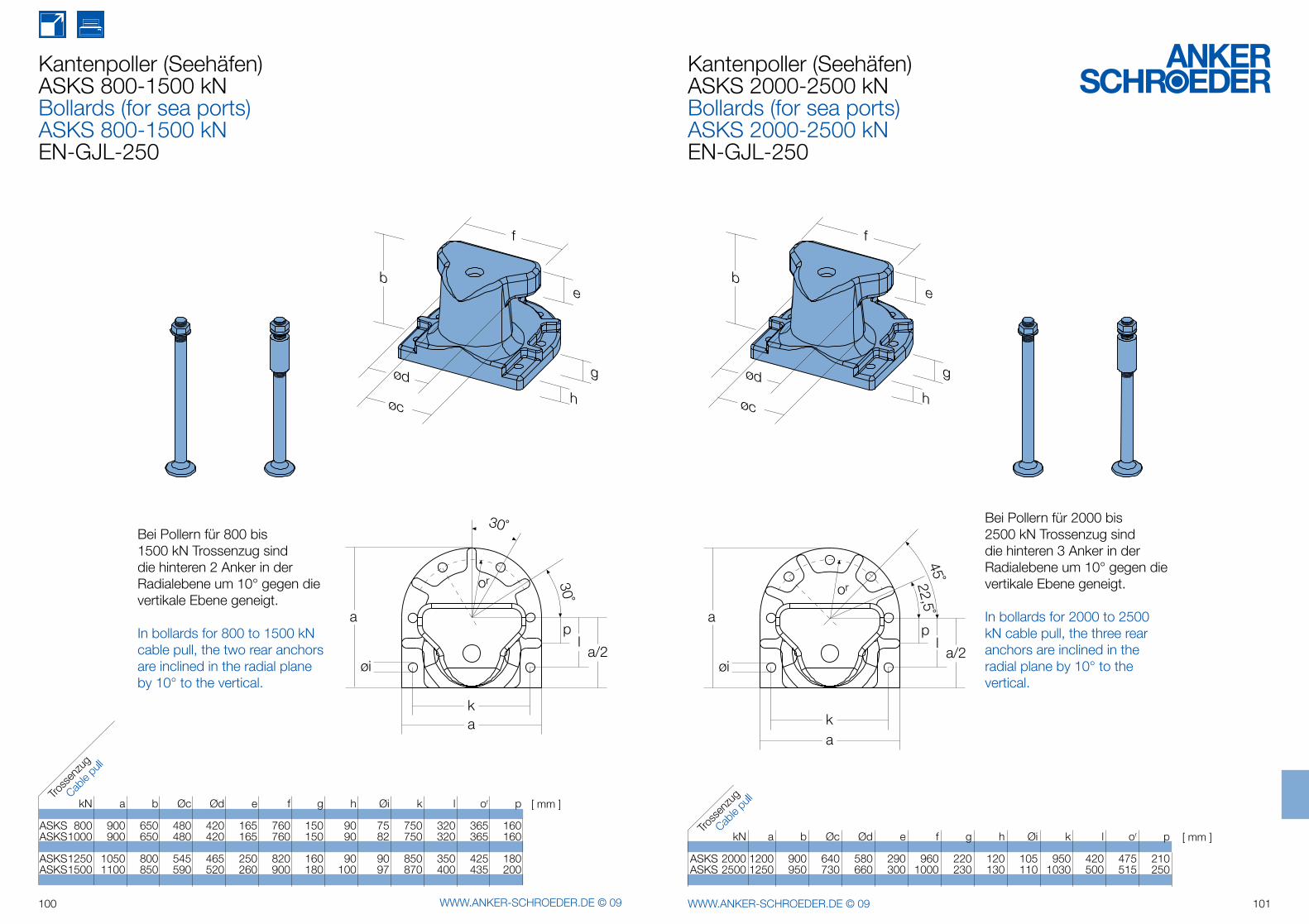
f
e
ød
øch
g
b
øi
ka
a
la/2
or
30˚
30˚
p
f
e
ød
øch
g
b
øi
ka
or
a
a/2
pl
22,5˚45˚
100 WWW.ANKER-SCHROEDER.DE © 09 101WWW.ANKER-SCHROEDER.DE © 09
Kantenpoller (Seehäfen) ASKS 800-1500 kNBollards (for sea ports)ASKS 800-1500 kNEN-GJL-250
Bei Pollern für 800 bis 1500 kN Trossenzug sind die hinteren 2 Anker in der Radialebene um 10° gegen die vertikale Ebene geneigt.
In bollards for 800 to 1500 kN cable pull, the two rear anchors are inclined in the radial plane by 10° to the vertical.
Kantenpoller (Seehäfen)ASKS 2000-2500 kNBollards (for sea ports)ASKS 2000-2500 kNEN-GJL-250
Bei Pollern für 2000 bis 2500 kN Trossenzug sind die hinteren 3 Anker in der Radialebene um 10° gegen die vertikale Ebene geneigt.
In bollards for 2000 to 2500 kN cable pull, the three rear anchors are inclined in the radial plane by 10° to the vertical.
kN a b Øc Ød e f g h Øi k l or p
ASKS 800 900 650 480 420 165 760 150 90 75 750 320 365 160ASKS 1000 900 650 480 420 165 760 150 90 82 750 320 365 160
ASKS 1250 1050 800 545 465 250 820 160 90 90 850 350 425 180ASKS 1500 1100 850 590 520 260 900 180 100 97 870 400 435 200
kN a b Øc Ød e f g h Øi k l or p
ASKS 2000 1200 900 640 580 290 960 220 120 105 950 420 475 210 ASKS 2500 1250 950 730 660 300 1000 230 130 110 1030 500 515 250
Tross
enzu
g
Cable
pulll
Tross
enzu
g
Cable
pulll[ mm ]
[ mm ]
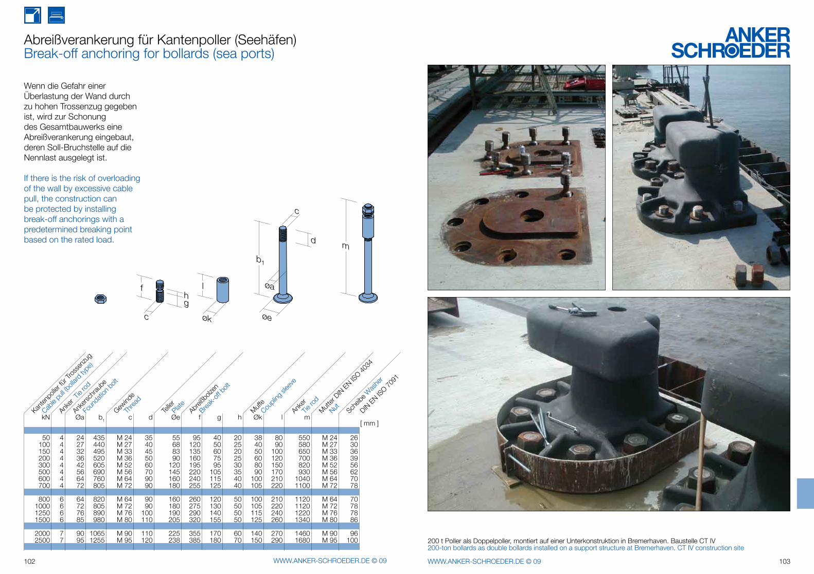
m
økc øe
c
øa
d
l
gh
b1
f
102 WWW.ANKER-SCHROEDER.DE © 09 103WWW.ANKER-SCHROEDER.DE © 09
Abreißverankerung für Kantenpoller (Seehäfen)Break-off anchoring for bollards (sea ports)
Wenn die Gefahr einer Überlastung der Wand durch zu hohen Trossenzug gegeben ist, wird zur Schonung des Gesamtbauwerks eine Abreißverankerung eingebaut, deren Soll-Bruchstelle auf die Nennlast ausgelegt ist.
If there is the risk of overloading of the wall by excessive cable pull, the construction can be protected by installing break-off anchorings with a predetermined breaking point based on the rated load.
200 t Poller als Doppelpoller, montiert auf einer Unterkonstruktion in Bremerhaven. Baustelle CT IV200-ton bollards as double bollards installed on a support structure at Bremerhaven. CT IV construction site
kN Øa b1 c d Øe f g h Øk l m
50 4 24 435 M 24 35 55 95 40 20 38 80 550 M 24 26 100 4 27 440 M 27 40 68 120 50 25 40 90 580 M 27 30 150 4 32 495 M 33 45 83 135 60 20 50 100 650 M 33 36 200 4 36 520 M 36 50 90 160 75 25 60 120 700 M 36 39 300 4 42 605 M 52 60 120 195 95 30 80 150 820 M 52 56 500 4 56 690 M 56 70 145 220 105 35 90 170 930 M 56 62 600 4 64 760 M 64 90 160 240 115 40 100 210 1040 M 64 70 700 4 72 805 M 72 90 180 255 125 40 105 220 1100 M 72 78
800 6 64 820 M 64 90 160 260 120 50 100 210 1120 M 64 70 1000 6 72 805 M 72 90 180 275 130 50 105 220 1120 M 72 78 1250 6 76 890 M 76 100 190 290 140 50 115 240 1220 M 76 78 1500 6 85 980 M 80 110 205 320 155 50 125 260 1340 M 80 86
2000 7 90 1065 M 90 110 225 355 170 60 140 270 1460 M 90 96 2500 7 95 1255 M 95 120 238 385 180 70 150 290 1680 M 95 100
Cable
pull (
bolla
rd ty
pe)
Kanten
polle
r fürTro
ssen
zug
Anker
Tie ro
d
Telle
rAbr
eißbo
lzen
Break-
off b
olt
Ankers
chrau
be
Foun
datio
n bolt
Gewind
e
MuffeCou
pling
slee
ve
Anker
Mutter
DINEN
ISO
4034
Scheib
e Was
her
Threa
d
Plate
Tie ro
d
Nut DIN
EN IS
O 7091
[ mm ]
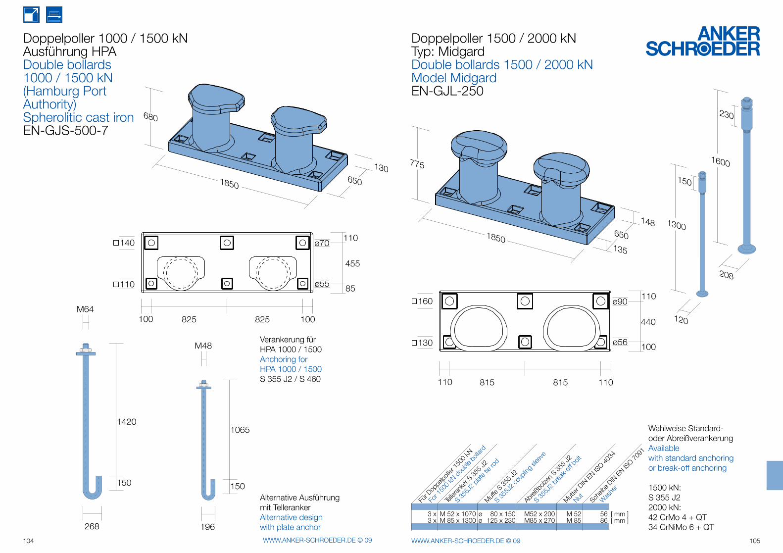
680
1306501850
110
85
455
100 100825 825
ø70
ø55
140
110
268
M64
1420
150
196
M48
1065
150
775
1486501850135
110
100
440
110 110815 815
ø90
ø56
160
130
120
208
150
230
1600
1300
104 WWW.ANKER-SCHROEDER.DE © 09 105WWW.ANKER-SCHROEDER.DE © 09
Doppelpoller 1000 / 1500 kN Ausführung HPA Double bollards1000 / 1500 kN(Hamburg Port Authority)Spherolitic cast ironEN-GJS-500-7
Verankerung fürHPA 1000 / 1500Anchoring forHPA 1000 / 1500S 355 J2 / S 460
Alternative Ausführung mit TellerankerAlternative design with plate anchor
Doppelpoller 1500 / 2000 kNTyp: MidgardDouble bollards 1500 / 2000 kNModel MidgardEN-GJL-250
Wahlweise Standard- oder AbreißverankerungAvailable with standard anchoring or break-off anchoring
1500 kN:S 355 J22000 kN:42 CrMo 4 + QT 34 CrNiMo 6 + QT
3 x M 52 x 1070 ø 80 x 150 M52 x 200 M 52 56 3 x M 85 x 1300 ø 125 x 230 M85 x 270 M 85 86
For 1
500 k
N dou
ble b
ollard
Für D
oppe
lpolle
r 150
0 kN
Abreiß
bolze
n S35
5 J2
Telle
ranke
r S35
5 J2
S 355J
2 plat
e tie
rod
Muffe S
355 J2
Mutter
DINEN
ISO
4034
Scheib
e DINEN
ISO
7091
S 355J
2 cou
pling
slee
ve
S 355J
2 brea
k-off
bolt
Nut Was
her
[ mm ][ mm ]
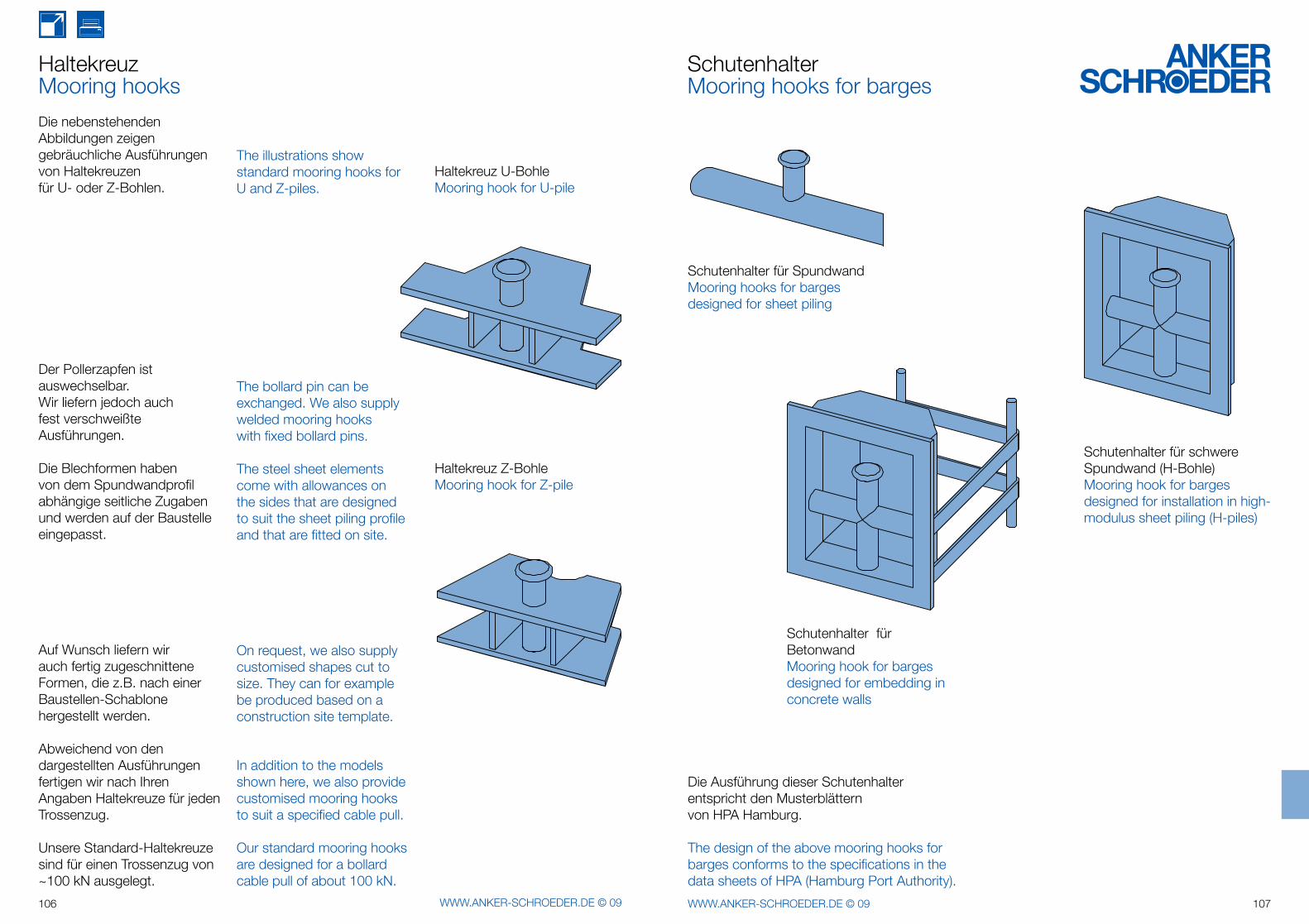
106 WWW.ANKER-SCHROEDER.DE © 09 107WWW.ANKER-SCHROEDER.DE © 09
Haltekreuz U-BohleMooring hook for U-pile
Haltekreuz Z-BohleMooring hook for Z-pile
HaltekreuzMooring hooks
Die nebenstehenden Abbildungen zeigen gebräuchliche Aus führungen von Haltekreuzen für U- oder Z-Bohlen.
Der Pollerzapfen ist auswechselbar. Wir liefern jedoch auch fest verschweißte Ausführungen.
Die Blechformen haben von dem Spundwandprofil abhängige seitliche Zugaben und werden auf der Baustelle eingepasst.
Auf Wunsch liefern wir auch fertig zugeschnittene Formen, die z.B. nach einer Baustellen-Schablone hergestellt werden.
Abweichend von den dargestellten Aus führungen fertigen wir nach Ihren Angaben Haltekreuze für jeden Trossen zug.
Unsere Standard-Haltekreuze sind für einen Trossenzug von ~100 kN ausgelegt.
The illustrations showstandard mooring hooks forU and Z-piles.
The bollard pin can be exchanged. We also supply welded mooring hooks with fixed bollard pins.
The steel sheet elements come with allowances on the sides that are designed to suit the sheet piling profile and that are fitted on site.
On request, we also supply customised shapes cut to size. They can for example be produced based on a construction site template.
In addition to the models shown here, we also provide customised mooring hooks to suit a specified cable pull.
Our standard mooring hooks are designed for a bollard cable pull of about 100 kN.
Schutenhalter für BetonwandMooring hook for barges designed for embedding in concrete walls
Schutenhalter für schwere Spundwand (H-Bohle)Mooring hook for barges designed for installation in high-modulus sheet piling (H-piles)
Schutenhalter für SpundwandMooring hooks for barges designed for sheet piling
SchutenhalterMooring hooks for barges
Die Ausführung dieser Schutenhalter entspricht den Musterblätternvon HPA Hamburg.
The design of the above mooring hooks for barges conforms to the specifications in the data sheets of HPA (Hamburg Port Authority).
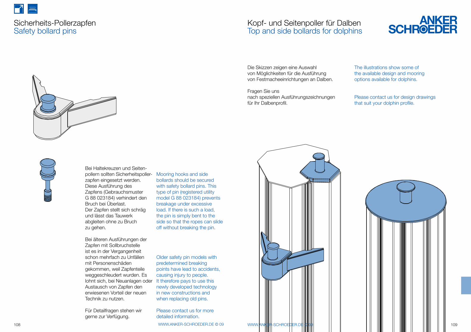
108 WWW.ANKER-SCHROEDER.DE © 09 109WWW.ANKER-SCHROEDER.DE © 09
Bei Haltekreuzen und Seiten-pollern sollten Sicherheitspoller-zapfen eingesetzt werden. Diese Ausführung des Zapfens (Gebrauchsmuster G 88 023184) verhin dert den Bruch bei Überlast. Der Zapfen stellt sich schräg und lässt das Tauwerk abgleiten ohne zu Bruch zu gehen.
Bei älteren Ausführungen der Zapfen mit Sollbruchstelle ist es in der Vergangenheit schon mehrfach zu Unfällen mit Personenschäden gekom men, weil Zapfenteile weggeschleudert wurden. Es lohnt sich, bei Neuanlagen oder Austausch von Zapfen den erwiesenen Vorteil der neuen Technik zu nutzen.
Für Detailfragen stehen wir gerne zur Verfügung.
Mooring hooks and side bollards should be secured with safety bollard pins. This type of pin (registered utility model G 88 023184) prevents breakage under excessive load. If there is such a load, the pin is simply bent to the side so that the ropes can slide off without breaking the pin.
Older safety pin models with predetermined breaking points have lead to accidents, causing injury to people.It therefore pays to use this newly developed technology in new constructions and when replacing old pins.
Please contact us for more detailed information.
Sicherheits-PollerzapfenSafety bollard pins
Die Skizzen zeigen eine Auswahl von Möglichkeiten für die Ausführung von Festmache einrichtungen an Dalben.
Fragen Sie uns nach speziellen Ausfüh rungs zeichnungen für Ihr Dalben profil.
The illustrations show some of the available design and mooring options available for dolphins.
Please contact us for design drawings that suit your dolphin profile.
Kopf- und Seitenpoller für DalbenTop and side bollards for dolphins
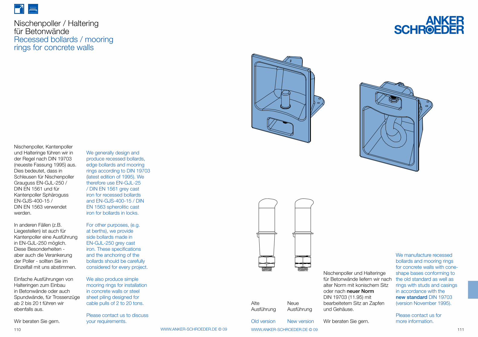
110 WWW.ANKER-SCHROEDER.DE © 09 111WWW.ANKER-SCHROEDER.DE © 09
Nischenpoller, Kantenpoller und Halteringe führen wir in der Regel nach DIN 19703 (neueste Fassung 1995) aus.Dies bedeutet, dass in Schleusen für Nischenpoller Grauguss EN-GJL-250 / DIN EN 1561 und für Kantenpoller Sphäroguss EN-GJS-400-15 / DIN EN 1563 verwendet werden.
In anderen Fällen (z.B. Liegestellen) ist auch für Kantenpoller eine Ausführung in EN-GJL-250 möglich.Diese Besonderheiten -aber auch die Verankerung der Poller - sollten Sie im Einzelfall mit uns abstimmen.
Einfache Ausführungen von Halteringen zum Einbau in Betonwände oder auch Spundwände, für Trossenzüge ab 2 bis 20 t führen wir ebenfalls aus.
Wir beraten Sie gern.
We generally design and produce recessed bollards, edge bollards and mooring rings according to DIN 19703 (latest edition of 1995). We therefore use EN-GJL-25 / DIN EN 1561 grey cast iron for recessed bollards and EN-GJS-400-15 / DIN EN 1563 spherolitic cast iron for bollards in locks.
For other purposes, (e.g. at berths), we provide side bollards made in EN-GJL-250 grey cast iron. These specifications and the anchoring of the bollards should be carefully considered for every project.
We also produce simple mooring rings for installation in concrete walls or steel sheet piling designed for cable pulls of 2 to 20 tons.
Please contact us to discuss your requirements.
Nischenpoller / Haltering für BetonwändeRecessed bollards / mooring rings for concrete walls
Nischenpoller und Halteringe für Betonwände liefern wir nach alter Norm mit konischem Sitz oder nach neuer NormDIN 19703 (11.95) mitbearbeitetem Sitz an Zapfen und Gehäuse.
Wir beraten Sie gern.
We manufacture recessed bollards and mooring rings for concrete walls with cone-shape bases conforming to the old standard as well as rings with studs and casings in accordance with the new standard DIN 19703 (version November 1995).
Please contact us for more information.
AlteAusführung
Old version
NeueAusführung
New version
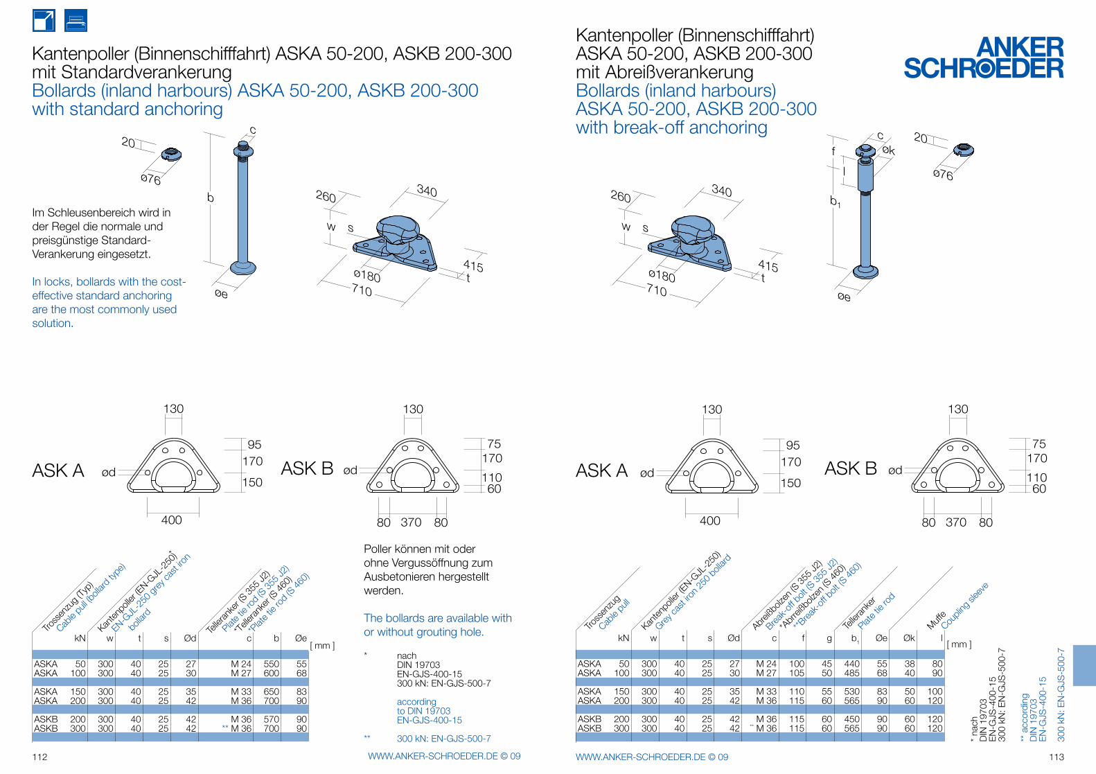
ASK A ASK B
20
ø76
130
95170
150
400
ød
130
75170
110
370
ød
60
8080
øe
b
c
ø180
340
415
710
w
260
t
s
ASK A ASK B
20
ø76
130
95170
150
400
ød
130
75170
110
370
ød
60
8080
ø180
340
415
710
w
260
t
s
øe
b1
økc
l
f
112 WWW.ANKER-SCHROEDER.DE © 09 113WWW.ANKER-SCHROEDER.DE © 09
Kantenpoller (Binnenschifffahrt) ASKA 50-200, ASKB 200-300mit StandardverankerungBollards (inland harbours) ASKA 50-200, ASKB 200-300with standard anchoring
Im Schleusenbereich wird in der Regel die normale und preisgünstige Standard-Verankerung eingesetzt.
In locks, bollards with the cost-effective standard anchoring are the most commonly used solution.
Kantenpoller (Binnenschifffahrt) ASKA 50-200, ASKB 200-300mit AbreißverankerungBollards (inland harbours)ASKA 50-200, ASKB 200-300with break-off anchoring
Poller können mit oder ohne Vergussöffnung zum Ausbetonieren hergestellt werden.
The bollards are available with or without grouting hole.
* nach DIN 19703 EN-GJS-400-15 300 kN: EN-GJS-500-7
according to DIN 19703 EN-GJS-400-15
** 300 kN: EN-GJS-500-7 * na
chD
IN 1
9703
E
N-G
JS-4
00-1
530
0 kN
: EN
-GJS
-500
-7
** a
ccor
ding
DIN
197
03E
N-G
JS-4
00-1
5
300
kN: E
N-G
JS-5
00-7
kN w t s Ød c f g b1 Øe Øk l
ASKA 50 300 40 25 27 M 24 100 45 440 55 38 80 ASKA 100 300 40 25 30 M 27 105 50 485 68 40 90
ASKA 150 300 40 25 35 M 33 110 55 530 83 50 100 ASKA 200 300 40 25 42 M 36 115 60 565 90 60 120
ASKB 200 300 40 25 42 M 36 115 60 450 90 60 120 ASKB 300 300 40 25 42 ** M 36 115 60 565 90 60 120
kN w t s Ød c b Øe
ASKA 50 300 40 25 27 M 24 550 55 ASKA 100 300 40 25 30 M 27 600 68
ASKA 150 300 40 25 35 M 33 650 83 ASKA 200 300 40 25 42 M 36 700 90
ASKB 200 300 40 25 42 M 36 570 90 ASKB 300 300 40 25 42 ** M 36 700 90
Tross
enzu
g (Ty
p)
Cable
pull (
bolla
rd ty
pe)
Kanten
polle
r (EN-GJL
-250
)*
EN-GJL
-250
grey
cast
iron
b
ollard
Telle
ranke
r (S35
5 J2)
Plate tie
rod
(S35
5 J2)
*Tell
erank
er (S
460)
*Plat
e tie
rod
(S 46
0)
[ mm ]
Tross
enzu
g
Cable
pull
Kanten
polle
r (EN-GJL
-250
)
Grey ca
st iro
n 250
boll
ard
Abreiß
bolze
n (S35
5 J2)
Break-
off b
olt (S
355 J
2)
Telle
ranke
r
Plate t
ie ro
d
MuffeCou
pling
slee
ve
*Abr
reißb
olzen
(S 46
0)
**Brea
k-off
bolt
(S 46
0)
[ mm ]
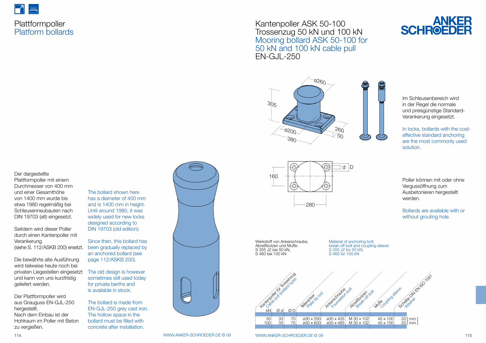
50
305
380
ø260
260ø200
d D
280
160
114 WWW.ANKER-SCHROEDER.DE © 09 115WWW.ANKER-SCHROEDER.DE © 09
PlattformpollerPlatform bollards
The bollard shown here has a diameter of 400 mm and is 1400 mm in height. Until around 1980, it was widely used for new locks designed according to DIN 19703 (old edition).
Since then, this bollard has been gradually replaced by an anchored bollard (see page 112/ASKB 200).
The old design is however sometimes still used today for private berths and is available in stock.
The bollard is made from EN-GJL-250 grey cast iron. The hollow space in the bollard must be filled with concrete after installation.
Der dargestellte Plattformpoller mit einem Durchmesser von 400 mm und einer Gesamthöhe von 1400 mm wurde bis etwa 1980 regelmäßig bei Schleusenneubauten nach DIN 19703 (alt) eingesetzt.
Seitdem wird dieser Poller durch einen Kantenpoller mit Verankerung (siehe S. 112/ASKB 200) ersetzt.
Die bewährte alte Ausführung wird teil weise heute noch bei privaten Liegestellen eingesetzt und kann von uns kurzfristig geliefert werden.
Der Plattformpoller wird aus Grauguss EN-GJL-250 hergestellt.Nach dem Einbau ist der Hohlraum im Poller mit Beton zu vergießen.
Kantenpoller ASK 50-100Trossenzug 50 kN und 100 kNMooring bollard ASK 50-100 for 50 kN and 100 kN cable pullEN-GJL-250
Werkstoff von Ankerschraube,Abreißbolzen und Muffe:S 355 J2 bei 50 kN,S 460 bei 100 kN
Material of anchoring bolt,break-off bolt and coupling sleeve:S 355 J2 for 50 kN,S 460 for 100 kN
Im Schleusenbereich wirdin der Regel die normaleund preisgünstige Standard-Verankerung eingesetzt.
In locks, bollards with the cost-effective standard anchoring are the most commonly used solution.
Poller können mit oder ohneVergussöffnung zumAusbetonieren hergestelltwerden.
Bollards are available with or without grouting hole.
kN Ø d Ø D
50 33 70 ø30 x 550 ø30 x 435 M 30 x 102 45 x 100 33 100 33 70 ø30 x 600 ø30 x 485 M 30 x 102 45 x 100 33
Abreiß
bolze
n
Telle
ranke
r
Plate t
ie ro
d
Ankers
chrau
be
Muffe
Foun
datio
n bolt
Break-
off b
olt
Coupli
ng sl
eeve
Kanten
polle
r fürTro
ssen
zug
Cable
pull (
bolla
rd ty
pe)
Was
her
Scheib
e DINEN
ISO
7091
[ mm ][ mm ]
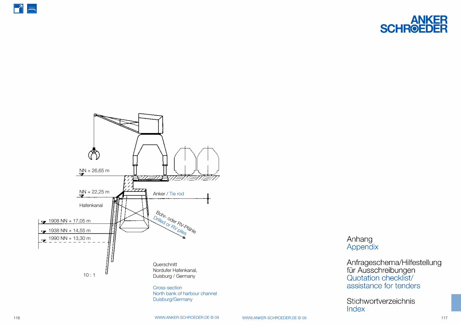
NN + 26,65 m
NN + 22,25 m
Hafenkanal
1908 NN + 17,05 m
1938 NN + 14,55 m
1990 NN + 13,30 m
10 : 1
Bohr- oder RV-Pfähle
Drilled or RV piles
Anker / Tie rod
Querschnitt Nordufer Hafenkanal,Duisburg / Germany
Cross-sectionNorth bank of harbour channelDuisburg/Germany
116 WWW.ANKER-SCHROEDER.DE © 09 117WWW.ANKER-SCHROEDER.DE © 09
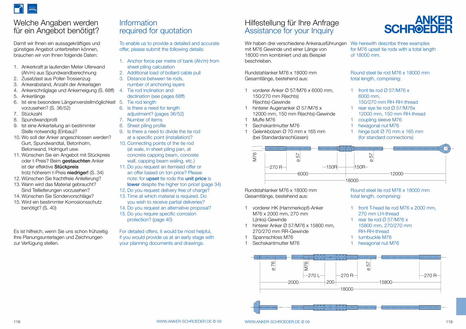
M76
18000
270 R6000
150R 150R
ø 57
ø 57
12000
18000
270 L200
270 R 270 R2000 15800
ø 76
M76
ø 57
118 WWW.ANKER-SCHROEDER.DE © 09 119WWW.ANKER-SCHROEDER.DE © 09
Damit wir Ihnen ein aussagekräftiges und günstiges Angebot unterbreiten können, brauchen wir von Ihnen folgende Daten:
1. Ankerkraft je laufenden Meter Uferwand (Ah/m) aus Spundwandberechnung2. Zusatzlast aus Poller-Trossenzug3. Ankerabstand, Anzahl der Ankerlagen4. Ankerschräglage und Ankerneigung (S. 68ff)5. Ankerlänge6. Ist eine besondere Längenverstellmöglichkeit vorzusehen? (S. 36/52)7. Stückzahl8. Spundwandprofil9. Ist eine Ankerteilung an bestimmter Stelle notwendig (Einbau)?10. Wo soll der Anker angeschlossen werden? Gurt, Spundwandtal, Betonholm, Betonwand, Holmgurt usw.11. Wünschen Sie ein Angebot mit Stückpreis oder t-Preis? Beim gestauchten Anker ist der effektive Stückpreis trotz höherem t-Preis niedriger! (S. 34)12. Wünschen Sie frachtfreie Anlieferung?13. Wann wird das Material gebraucht? Sind Teillieferungen vorzusehen?14. Wünschen Sie Sondervorschläge?15. Wird ein bestimmter Korrosionsschutz benötigt? (S. 40)
Es ist hilfreich, wenn Sie uns schon frühzeitigIhre Planungsunterlagen und Zeichnungenzur Verfügung stellen.
To enable us to provide a detailed and accurate offer, please submit the following details:
1. Anchor force per metre of bank (Ah/m) from sheet piling calculation2. Additional load of bollard cable pull3. Distance between tie rods, number of anchoring layers4. Tie rod inclination and declination (see pages 68ff)5. Tie rod length6. Is there a need for length adjustment? (pages 36/52)7. Number of items8. Sheet piling profile9. Is there a need to divide the tie rod at a specific point (installation)?10. Connecting points of the tie rod (at wale, in sheet piling pan, at concrete capping beam, concrete wall, capping beam waling, etc.)11. Do you request an itemised offer or an offer based on ton price? Please note: for upset tie rods the unit price is lower despite the higher ton price! (page 34)12. Do you request delivery free of charge?13. Time at which material is required. Do you wish to receive partial deliveries?14. Do you request an alternative proposal?15. Do you require specific corrosion protection? (page 40)
For detailed offers, it would be most helpful, if you would provide us at an early stage with your planning documents and drawings.
Information required for quotation
Welche Angaben werdenfür ein Angebot benötigt?
Wir haben drei verschiedene Ankerausführungen mit M76 Gewinde und einer Länge von18000 mm kombiniert und als Beispiel beschrieben.
Rundstahlanker M76 x 18000 mmGesamtlänge, bestehend aus:
1 vorderer Anker Ø 57/M76 x 6000 mm, 150/270 mm R(echts) R(echts)-Gewinde1 hinterer Augenanker Ø 57/M76 x 12000 mm, 150 mm R(echts)-Gewinde1 Muffe M761 Sechskantmutter M761 Gelenkbolzen Ø 70 mm x 165 mm (bei Standardanschlüssen)
Rundstahlanker M76 x 18000 mmGesamtlänge, bestehend aus:
1 vorderer HK (Hammerkopf)-Anker M76 x 2000 mm, 270 mm L(inks)-Gewinde1 hinterer Anker Ø 57/M76 x 15800 mm, 270/270 mm RR-Gewinde1 Spannschloss M761 Sechskantmutter M76
We herewith describe three examplesfor M76 upset tie rods with a total lengthof 18000 mm.
Round steel tie rod M76 x 18000 mmtotal length, comprising:
1 front tie rod Ø 57/M76 x 6000 mm, 150/270 mm RH-RH-thread1 rear eye tie rod Ø 57/M76x 12000 mm, 150 mm RH-thread1 coupling sleeve M761 hexagonal nut M761 hinge bolt Ø 70 mm x 165 mm (for standard connections)
Round steel tie rod M76 x 18000 mmtotal length, comprising:
1 front T-head tie rod M76 x 2000 mm, 270 mm LH-thread1 rear tie rod Ø 57/M76 x 15800 mm, 270/270 mm RH-RH-thread1 turnbuckle M761 hexagonal nut M76
Hilfestellung für Ihre AnfrageAssistance for your Inquiry
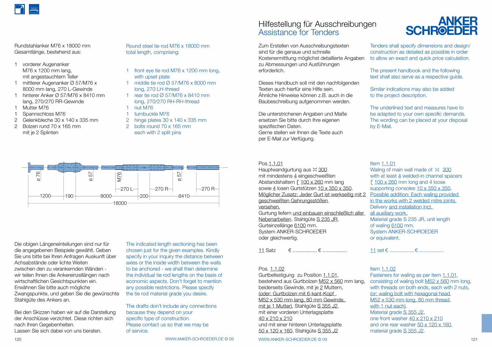
18000
1200 190 8000270 L
200270 R
8410270 R
ø 76
ø 57
ø 57
M76
120 WWW.ANKER-SCHROEDER.DE © 09 121WWW.ANKER-SCHROEDER.DE © 09
Die obigen Längeneinteilungen sind nur für die angegebenen Beispiele gewählt. Geben Sie uns bitte bei Ihren Anfragen Auskunft über Achsabstände oder lichte Weiten zwischen den zu verankernden Wänden - wir teilen Ihnen die Ankereinzel längen nach wirtschaftlichen Gesichtspunkten ein. Erwähnen Sie bitte auch mögliche Zwangspunkte, und geben Sie die gewünschte Stahlgüte des Ankers an.
Bei den Skizzen haben wir auf die Darstellung der Anschlüsse verzichtet. Diese richten sich nach Ihren Gegebenheiten. Lassen Sie sich dabei von uns beraten.
The indicated length sectioning has been chosen just for the given examples. Kindly specify in your inquiry the distance between axles or the inside width between the walls to be anchored - we shall then determine the individual tie rod lengths on the basis of economic aspects. Don’t forget to mention any possible restrictions. Please specify the tie rod material grade you desire.
The drafts don’t include any connections because they depend on your specific type of construction. Please contact us so that we may be of service.
Rundstahlanker M76 x 18000 mm Gesamtlänge, bestehend aus:
1 vorderer Augenanker M76 x 1200 mm lang, mit angestauchtem Teller1 mittlerer Augenanker Ø 57/M76 x 8000 mm lang, 270 L-Gewinde1 hinterer Anker Ø 57/M76 x 8410 mm lang, 270/270 RR-Gewinde1 Mutter M761 Spannschloss M762 Gelenkbleche 30 x 140 x 335 mm2 Bolzen rund 70 x 165 mm mit je 2 Splinten
Round steel tie rod M76 x 18000 mm total length, comprising:
1 front eye tie rod M76 x 1200 mm long, with upset plate1 middle tie rod Ø 57/M76 x 8000 mm long, 270 LH-thread1 rear tie rod Ø 57/M76 x 8410 mm long, 270/270 RH-RH-thread1 nut M761 turnbuckle M762 hinge plates 30 x 140 x 335 mm2 bolts round 70 x 165 mm each with 2 split pins
Hilfestellung für AusschreibungenAssistance for Tenders
Zum Erstellen von Ausschreibungstexten sind für die genaue und schnelle Kostenermittlung möglichst detaillierte Angaben zu Abmessungen und Ausführungen erforderlich.
Dieses Handbuch soll mit den nachfolgenden Texten auch hierfür eine Hilfe sein.Ähnliche Hinweise können z.B. auch in die Baubeschreibung aufgenommen werden.
Die unterstrichenen Angaben und Maße ersetzen Sie bitte durch Ihre eigenen spezifischen Daten.Gerne stellen wir Ihnen die Texte auch per E-Mail zur Verfügung.
Pos.1.1.01 Hauptwandgurtung aus ][ 300 mit mindestens 4 eingeschweißten Abstandshaltern [ 100 x 260 mm lang sowie 4 losen Gurtstützen 10 x 350 x 350.Möglicher Zusatz: Jeder Gurt ist werkseitig mit 2 geschweißten Gehrungsstößen versehen.Gurtung liefern und einbauen einschließlich aller Nebenarbeiten. Stahlgüte S 235 JR, Gurteinzellänge 6100 mm.System ANKER-SCHROEDER oder gleichwertig.
11 Satz € ................. € .................
Pos. 1.1.02 Gurtbefestigung zu Position 1.1.01, bestehend aus Gurtbolzen M52 x 560 mm lang, beiderseits Gewinde, mit je 2 Muttern,(oder: Gurtbolzen mit 6-kant-Kopf M52 x 530 mm lang, 80 mm Gewinde, mit je 1 Mutter), Stahlgüte S 355 J2, mit einer vorderen Unterlagsplatte 40 x 210 x 210 und mit einer hinteren Unterlagsplatte 50 x 120 x 160, Stahlgüte S 355 J2
Tenders shall specify dimensions and design/construction as detailed as possible in order to allow an exact and quick price calculation.
The present handbook and the following text shall also serve as a respective guide.
Similar indications may also be added to the project description.
The underlined text and measures have tobe adapted to your own specific demands.The wording can be placed at your disposal by E-Mail.
Item 1.1.01 Waling of main wall made of ][ 300 with at least 4 welded-in channel spacers [ 100 x 260 mm long and 4 loose supporting consoles 10 x 350 x 350.Possible addition: Each waling provided in the works with 2 welded mitre joints.Delivery and installation incl. all auxiliary work.Material grade S 235 JR, unit length of waling 6100 mm.System ANKER-SCHROEDER or equivalent.
11 set € ................. € .................
Item 1.1.02 Fasteners for waling as per item 1.1.01, consisting of waling bolt M52 x 560 mm long, with threads on both ends, each with 2 nuts, (or: waling bolt with hexagonal head M52 x 530 mm long, 80 mm thread, with 1 nut each).Material grade S 355 J2,one front washer 40 x 210 x 210and one rear washer 50 x 120 x 160, material grade S 355 J2.
122 WWW.ANKER-SCHROEDER.DE © 09 123WWW.ANKER-SCHROEDER.DE © 09
liefern und einbauen, einschließlich aller Nebenarbeiten. System ANKER-SCHROEDER oder gleichwertig.
77 Satz € ................. € .................
Pos. 1.1.03 Ankerwandgurtung aus ][ 300 mit mindestens 2 eingeschweißten Abstandshaltern [ 100 x 260 und 2 losen Gurtkonsolen liefern und einbauen, einschließlich aller Nebenarbeiten.Gurteinzellänge 2500 mm. Materialgüte S 235 JR.System ANKER-SCHROEDER oder gleichwertig.
11 Satz € ................. € .................
Pos. 1.1.04 Rundstahlanker M52 mit beiderseitigem Gewinde, 2 Muttern, einer vorderen Unterlagsplatte 50 x 120 x 160 und einer hinteren Unterlagsplatte 35 x 250 x 250 liefern und einbauen, einschließlich aller Nebenarbeiten. Ankerlänge 1300 mm. Stahlgüte S 355 J2.System ANKER-SCHROEDER oder gleichwertig.
22 Satz € ................. € .................
Pos. 1.1.05 Rundstahlanker wie Pos. 1.1.04, jedoch Länge 9000 mm.
22 Satz € ................. € .................
Pos. 1.1.06 Kantenpoller für 200 kN Trossenzug mit Unterkonstruktion zur Befestigung an der Spundwand, sowie Normalverankerung
Delivery and installation including all auxiliary work.System ANKER-SCHROEDER or equivalent.
77 set € ................. € .................
Item 1.1.03Waling of anchor wall ][ 300 with at least 2 welded-in channel spacers [ 100 x 260 and 2 loose support brackets. Delivery and installation including all auxiliary work.Unit length of waling 2500 mm. Material grade S 235 JR.System ANKER-SCHROEDER or equivalent.
11 set € ................. € .................
Item 1.1.04 Round steel tie rods M52, with threads on both ends,2 nuts, one front washer 50 x 120 x 160 and one rear washer35 x 250 x 250. Delivery and installation incl. all auxiliary work. Unit tie rod length1300 mm. Material grade S 355 J2.System ANKER-SCHROEDER or equivalent.
22 set € ................. € .................
Item 1.1.05 Round steel tie rods as per item 1.1.04, however with a length of 9000 mm.
22 set € ................. € .................
Item 1.1.06 Bollards for 200 kN cable pull with base construction for fixing to the sheet piling as well as standard anchorage M 39.
M 39 liefern und einbauen, einschließlich aller Nebenarbeiten. Ausführung siehe "Anker Handbuch '09" Seite 112/113jedoch Verankerung für Stahlkonstruktion.System ANKER-SCHROEDER oder gleichwertig.
11 Satz € ................. € .................
Pos. 1.1.07 Haltekreuze passend zum Spundwandprofil PU 20 für einen Trossenzug von 100 kN als Schweißkonstruktion liefern und einbauen, einschließlich aller Nebenarbeiten.Ausführung gemäß "Anker Handbuch '09" Seite 106 nach statischen und konstruktiven Erfordernissen.System ANKER-SCHROEDER oder gleichwertig.
22 Satz € ................. € .................
Pos. 1.1.08 Holmabdeckung mit/ohne Gleitschutz passend zum Spundwandprofil PU 20 einschließlich Winkel liefern und einbauen, einschließlich aller Nebenarbeiten. Erforderliche Eckausbildungen und Gehrungsschnitte sind in den Einheitspreis einzurechnen.Material S 235 JR. Abrechnung erfolgt nach Aufmaß in Spundwandachse. Ausführung siehe "Anker Handbuch '09" Seite 84ffSystem ANKER-SCHROEDER oder gleichwertig.
465 m € ................. € .................
Pos. 1.1.09 Haupt- und Ankerwandgurtung aus ][ 350 mit eingeschweißten Abstands-haltern [ 160 x 310 mm lang, a = 2,40 m,liefern und einbauen, einschließlich
Delivery and installation incl. all auxiliary work. Execution as specified on page 112/113 of "Anker Handbook '09",however with anchorage designed for steel construction.System ANKER-SCHROEDER or equivalent.
11 set € ................. € .................
Item 1.1.07 Mooring hooks fitting to sheet piling profile section PU 20 for a 100 kN cable pull as welding construction.Delivery and installation including all auxiliary work.Execution as specified on page 106 of "Anchor Handbook '09",with reference to static and constructional requirements.System ANKER-SCHROEDER or equivalent.
22 set € ................. € .................
Item 1.1.08 Profiled capping plates with/without non-slip surface fitting to sheet piling profile section PU 20 including angles. Delivery and installation including all auxiliary work. Necessary corners and mitre cuts to be included in unit price. Material grade S 235 JR. Accounting on the basis of final measurement at sheet piling axis. Execution as specified on page 84ff of "Anchor Handbook '09". System ANKER-SCHROEDER or equivalent.
465 m € ................. € .................
Item 1.1.09 Waling of main and anchor wall made of
][ 350 with welded-in channel spacers [ 160 x 310 mm long, a = 2.40 m. Delivery and installation including
124 WWW.ANKER-SCHROEDER.DE © 09 125WWW.ANKER-SCHROEDER.DE © 09
aller Nebenarbeiten.Gurtträgereinzellängen 14,40 m,Stöße gemäß "Anker Handbuch '09" Seite 23 geschraubt.Gurtkonsolen 400 x 400 x 12, a = 1,20 m. Stahlgüte S 235 JR.System ANKER-SCHROEDER oder gleichwertig.
370 m € ................. € .................
Pos. 1.1.10 Gurtbefestigung zu Position 1.1.09 bestehend aus Gurtbolzen mit Sechskantkopf M76 x 640 mm lang, einschließlich Mutter und erforderlicher Unterlagsplatten passend zum Spundwandprofil PU 32,Gurtspreizung s = 160 mm, liefern und einbauen,einschließlich aller Nebenarbeiten. Stahlgüte S 355 J2.System ANKER-SCHROEDER oder gleichwertig.
154 Satz € ................. € .................
Pos. 1.1.11 Rundstahlanker mit gestauchten Gewinden, Ø 57 / M76 x 15.000 mm, einschließlich aller Teile zum beiderseitigen gelenkigen Ankeranschluss,vorderer Anschluss: im Bohlental (oder z.B. am Gurt, in Beton),hinterer Anschluss: in Beton (gegebenenfalls bei Ankerneigung: mit Keilplatten zum Ausgleich einer Neigung von 10 Grad, Stahlgüte: S 355 J2).Anker durch 1 Spannschloss geteilt, Stahlgüte S 355 J2, liefern und einbauen, einschließlich aller Nebenarbeiten.Ausführung gemäß "Anker Handbuch '09" Seite 42/43 und Seite 68ff.
System ANKER-SCHROEDER oder gleichwertig.
51 Satz € ................. € .................
all auxiliary work. Unit length of waling profiles: 14.40 m. Waling joints screwed-on as specified on page 23 of "Anker Handbook '09".Support brackets 400 x 400 x 12, a = 1,20 m. Material grade S 235 JR. System ANKER-SCHROEDER or equivalent.
370 m € ................. € .................
Item 1.1.10 Fasteners for waling as per item 1.1.09, consisting of waling bolt with hexagonal head M76 x 640 mm long, incl. nut and necessary washers fitting to sheet piling profile section PU 32. Waling space: s = 160 mm.Delivery and installation including all auxiliary work. Material grade S 355 J2.System ANKER-SCHROEDER or equivalent.
154 set € ................. € .................
Item 1.1.11 Round steel tie rods with upset forged threads, Ø 57 / M76 x 15.000 mm, including all parts necessary for articulated connections on both ends, front connection: within the pan of the sheet pile (or the waling, in concrete),rear connection: in concrete.(If necessary, in case of an anchor declination: compensation of the 10 degree declination by wedge plate / tapered washer, material grade S 355 J2).Tie rod including 1 turnbuckle, material grade S 355 J2. Delivery and installation including all auxiliary work.Execution as specified on pages 42/43 and 68ff of "Anker Handbook '09".
System ANKER-SCHROEDER or equivalent.
51 set € ................. € .................
StichwortverzeichnisKeyword Register
Abnahme 11fAbreißverankerung für Poller 102Anfrage-Hilfe 118fAnker 33f, 42Anker für Poller 98fAufgestauchte Anker 34f, 38Augenanker 41,42, 43, 54, 72, 73
Betonwände 18, 80fBiegebelastung 54ff, 68f
Dimensionierung 36ff, 42DIN EN, Euronorm 37ffDoppelgelenk 56, 57Doppelpoller 104fDruckgurt 69
EAU 22, 34Exzentrische Verbindung 31
Gelenkige Verbindungen 53-57, 71ffGelenkscheibe 46, 61f, 70, 74Gelenkspannschloss 53Gelenkwirkung 53ff, 71ffGewindelänge 36, 42Gleichmaßdehnung 34Gurtbolzen 28, 29Gurtspreizung 22, 68Gurt, Gurtstoß, Gurtkonsole 21-24
Haltebügel 92Haltekreuz 106Haltering für Beton 110Hammerkopfanker 43, 54, 71, 79ffH-Bohlen-Anschluss 78Hintere Platte (Anker) 63, 64Hintere Platte (Gurtbolzen) 31Holmgurt 22Holmprofil 85ff
Inhalt 3
Kantenpoller (50 kN, 100 kN) 115Kantenpoller (Binnenhäfen) 112, 113Kantenpoller (Seehäfen) 96fKantenschutz für Beton 88f
allowable stress 35, 39anchor for bollards 99ffarticulated connections 67ff
bending loads 35, 74bollard for dolphin side 108fbollard for dolphin top 109bollards 95ffbreak-off anchor for bollards 97, 102, 105ff
capping profiles 85cardan joint 56fcoating 40concave nut 73concrete walls 80ff, 88, 93, 107, 110, 111connections 68ff, 78ffcorrosion protection 40coupler/coupling sleeve 52
declination 68, 69, 73, 118dimensioning 35, 78DIN EN, Euronorm 37DIN EN, European standard 37displacement-injected pile 46double bollard 103ff
EAU 22, 35eccentric connection 31excess load 35, 102, 108eye tie rod 72, 73, 79, 81, 119, 120
friction-type pile connection 49front plate for tie rod 59fffront plate for waling bolt 28ff
galvanizing 40general views 14-19
handrails 92high-modulus walls (connections) 77ffhinge effect 51, 70, 71, 72, 73, 81hinge joint 81
126 WWW.ANKER-SCHROEDER.DE © 09 127WWW.ANKER-SCHROEDER.DE © 09
inclination 68ff, 118imperial thread 37inspection 11, 12
ladder 91length of tie rods 36
metric thread 36fmooring bollard (50 kN, 100 kN) 115mooring hook 106mooring hooks for barges 107mooring ring (concrete wall) 110
plate 46, 60, 64, 82, 79plate nosing for concrete 88plate on concrete 82pressure waling 6protection during transport 41
quality 12
rear plate for tie rod 64rear plate for waling bolt 31recessed bollard (concrete) 93, 110frecess for ladder 90rocker plate 70, 74round head pin 49rubbing strip 89
safety bollard pin 108settlements 54, 68, 74sheet piling anchorage 14, 32spherical nut 75steel grades 37, 39, 47supporting bracket 24swivel plate 47, 70
Für die Vollständigkeit und Richtigkeit der in diesem Heft gemachten Angaben können wir trotz aller aufgewandter Sorgfalt keine Haftung übernehmen. Die Angaben stellen kein vertragliches Angebot dar. Änderungen behalten wir uns vor.
Allen unseren Geschäften liegen unsere allgemeinen Verkaufsbedingungen zugrunde, die wir Ihnen auf Wunsch gerne aktuell zusenden.
Although we have taken the greatest care in the preparation of the data for this handbook, we cannot assume responsibility for the completeness and correct-ness of all the details given. Each customer should satisfy himself of their suitability. These data must not be understood as contractual offer and we reserve the right to changes.
All our business is based on our general conditions of sale. We are pleased to send them on request.
T-Anschluss 78Telleranker für Poller 102Transportschutz 41
Überlastung 34Übersichten 14-19
Verankerungen 34-57Verankerung für Poller 102Verpressrohr 46Verzinkung 40Vordere Platte (Anker) 59ffVordere Platte (Gurtbolzen) 30
Wälzmutter 74Werkszeugnis 10
Zoll-Gewinde 37Zuggurt 69
tapered washer 69T-connection 78tensile resistance 39tension waling 69, 70T-head tie rod 43, 46, 71, 79, 81, 119thread length 36, 42tie rods 2, 4ff, 33ff, 118fftube wall connection 79turnbuckle 52, 119, 120turnbuckle hinge 53
uniform elongation 35upset tie rods 4, 34ff, 118f
waling bolts 27ffwaling joint 22, 23waling space 68wedge plate 69, 70, 124works certificate 10
Kardangelenk 56fKeilplatte 68fKonsole für Gurtung 24Kopfpoller für Dalben 109Korrosionsschutz 40Kugelmutter 75
Längen der Anker 36Laschengelenk 54Leiter 91
Metrisches Gewinde 34fMuffe 52
Neigung 68ffNische für Leiter 90Nischenpoller für Beton 110
Platte 30, 60, 64, 82Platte für Betonauflage 82Plattformpoller 114Poller 96ff
Qualität 12
Rammverpresspfahl 44fReibepfahlanschluss 49Rohrwand-Anschluss 79Rundkopfbolzen 49
Scheuerleiste 89Schräglage 68ffSchutenhalter 107Schwere Wände 16, 77fSeitenpoller für Dalben 109Setzungen 54, 68, 74Sicherheits-Pollerzapfen 108Spanschloss 52Spundwandabdeckung 86Spundwandverankerung 14, 32Stahlgüten 37Stoßdeckung 23