Embed Size (px)
Citation preview
• Notice de montage
• Instruction sheet
• Anweisungen
• Hoja de instrucciones
• Foglio istruzioni
• Folha de instruções
• BByyccnnhheerrwwbbbb
• Instrukcje monta˝u
• BBiillggii bbrrooflflüürrüü
05/2006-01 GF
8017
8LD
®
• Disjoncteurs débrochables
• Draw-out circuit breakers
• Herausnehmbare Selbstschalter
• Interruptores automáticos extraíbles
• Interruttori automatici estraibili
• Disjuntores extraíveis• CC]]ttvvyysstt ffddnnjjvvffnnbbxxttccrrbbtt
ddssrrkk..xxffnnttkkbb
• Wy∏àczniki samoczynne wysuwane• ÇÇeekkmmeellii oottoommaattiikk ddeevvrree kkeessiiccii aannaahhttaarrllaarr
DPX 1250 - DPX 1600 - DPX-I 1600
DPX
2
A B
C D
E H K I L
O P TRQ
M S
U
F
N
W
G
V Z
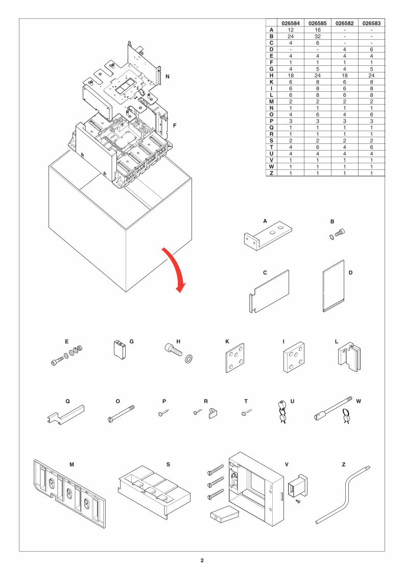
026584 026585 026582 026583A 12 16 - -B 24 32 - -C 4 6 - -D - - 4 6E 4 4 4 4F 1 1 1 1G 4 5 4 5H 18 24 18 24K 6 8 6 8I 6 8 6 8L 6 8 6 8M 2 2 2 2N 1 1 1 1O 4 6 4 6P 3 3 3 3Q 1 1 1 1R 1 1 1 1S 2 2 2 2T 4 6 4 6U 4 4 4 4V 1 1 1 1W 1 1 1 1Z 1 1 1 1
3
189
34
72.5146
140
253
360
171
12
13
325
360
127.4
50
26
109
25
482
72.5146
140
253
34.5 158.5
90
359
143.
512
5.5
13
325
360
127.4
26
34.5
Y
XX
XX
Y
3P= 250 4P= 325
3P= 250 4P= 325
ø 10
.4
ø 14
ø 10
.4
189
360
171
183
79
53
113
366
210
183
79
210
53
113
366
4
5
10Nm
5
10Nm
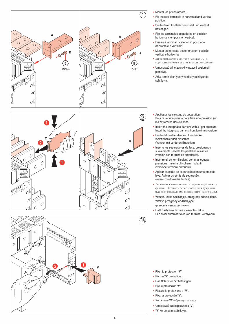
• Monter les prises arriére.
• Fix the rear terminals in horizontal and verticalposition.
• Die hinteren Endteile horizontal und vertikalbefestigen.
• Fije los terminales posteriores en posiciónhorizontal y en posición vertical.
• Fissare i terminali posteriori in posizioneorizzontale e verticale.
• Montar as tomadas posteriores em posiçãovertical e horizontal
• Pfrhtgbnm pflybt rjynfrnyst pf;bvs dujhbpjynfkmyjv b dthnbrfkmyjv gjkj;tybb
• Umocowaç tylne zaciski w pozycji poziomej ipionowej.
• Arka terminalleri yatay ve dikey pozisyondasabitleyin.
AB• Fixer la protection “V”.
• Fix the “V” protection.
• Das Schutzteil “V” befestigen.
• Fije la protección “V”.
• Fissare la protezione a “V”.
• Fixar a protecção “V”.
• Pfrhtgbnm “V”-j,hfpye. pfobne
• Umocowaç zabezpieczenie “V”.
• “V” korumasını sabitleyin.
1
A
B
A
B
V
A
A
B
• Appliquer les cloisons de séparation.Pour la version prise arriére faire une pression surles extremités des cloisons.
• Insert the interphase barriers with a light pressure.Insert the interphase barriers (front terminals version).
• Die Isolationsblenden leicht eindrücken.Isolationsblenden einsetzen(Version mit vorderen Endteilen)
• Inserte los separadores de fase, presionandosuavemente. Inserte las pantallas aislantes(versión con terminales anteriores).
• Inserire gli schermi isolanti con una leggerapressione. Inserire gli schermi isolanti(versione terminali anteriore).
• Aplicar os ecrãs de separação com uma pressãoleve. Aplicar os ecrãs de separação.(versão com tomadas frontais)
• Kturbv yf;fnbtv dcnfdbnm gthtujhjlrb vt;leafpfvb Dcnfdbnm gthtujhjlrb vt;le afpfvbødfhbfyn c gthtlybvb rjynfrnysvb pf;bvfvb
• W∏o˝yç, lekko naciskajàc, przegrody oddzielajàce.W∏o˝yç przegrody oddzielajàce.(przednia wersja zacisków)
• Hafif bastırarak faz arası ekranları takın.Faz arası ekranları takın (ön terminal versiyonu)
CD
2
3A
5
CLAC
A
BC
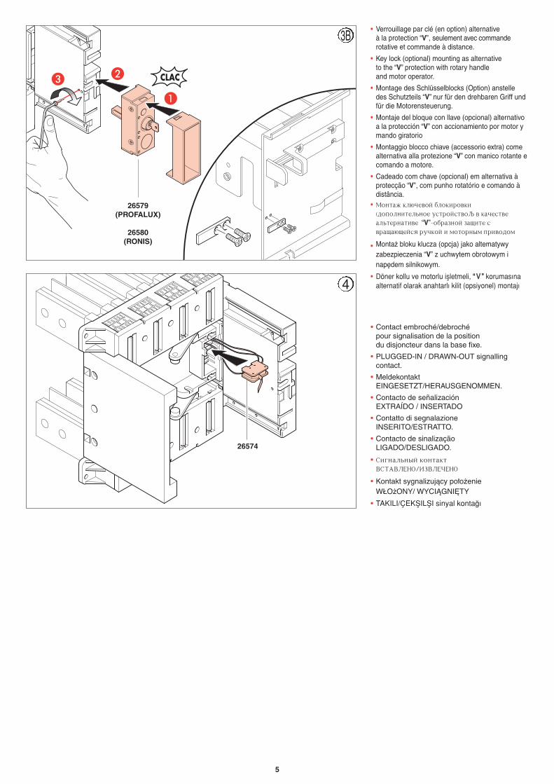
• Verrouillage par clé (en option) alternative à la protection “V”, seulement avec commanderotative et commande à distance.
• Key lock (optional) mounting as alternativeto the “V” protection with rotary handle and motor operator.
• Montage des Schlüsselblocks (Option) anstelledes Schutzteils “V” nur für den drehbaren Griff undfür die Motorensteuerung.
• Montaje del bloque con llave (opcional) alternativoa la protección “V” con accionamiento por motor ymando giratorio
• Montaggio blocco chiave (accessorio extra) comealternativa alla protezione “V” con manico rotante ecomando a motore.
• Cadeado com chave (opcional) em alternativa àprotecção “V”, com punho rotatório e comando àdistância.
• Vjynf; rk.xtdjq ,kjrbhjdrbøljgjkybntkmyjt ecnhjqcndj d rfxtcndtfkmnthyfnbdt “V”-j,hfpyjq pfobnt cdhfof.otqcz hexrjq b vjnjhysv ghbdjljv
• Monta˝ bloku klucza (opcja) jako alternatywyzabezpieczenia “V” z uchwytem obrotowym inap´dem silnikowym.
• Döner kollu ve motorlu iflletmeli, ““ VV ”” korumasınaalternatif olarak anahtarlı kilit (opsiyonel) montajı
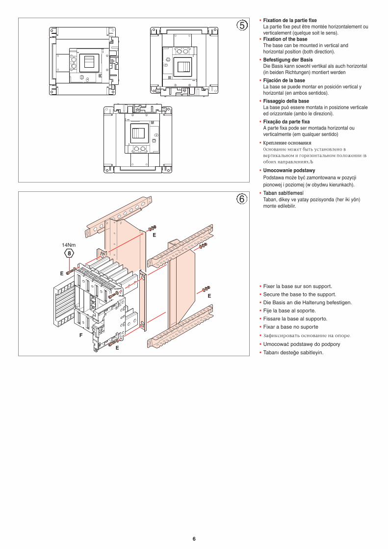
• Contact embroché/debrochépour signalisation de la position du disjoncteur dans la base fixe.
• PLUGGED-IN / DRAWN-OUT signallingcontact.
• MeldekontaktEINGESETZT/HERAUSGENOMMEN.
• Contacto de señalizaciónEXTRAÍDO / INSERTADO
• Contatto di segnalazioneINSERITO/ESTRATTO.
• Contacto de sinalizaçãoLIGADO/DESLIGADO.
• Cbuyfkmysq rjynfrnDCNFDKTYJ3BPDKTXTYJ
• Kontakt sygnalizujàcy po∏o˝enieW¸O˝ONY/ WYCIÑGNI¢TY
• TAKILI/ÇEKfiILfiI sinyal konta¤ı
26574
26579(PROFALUX)
26580(RONIS)
4
3B
6
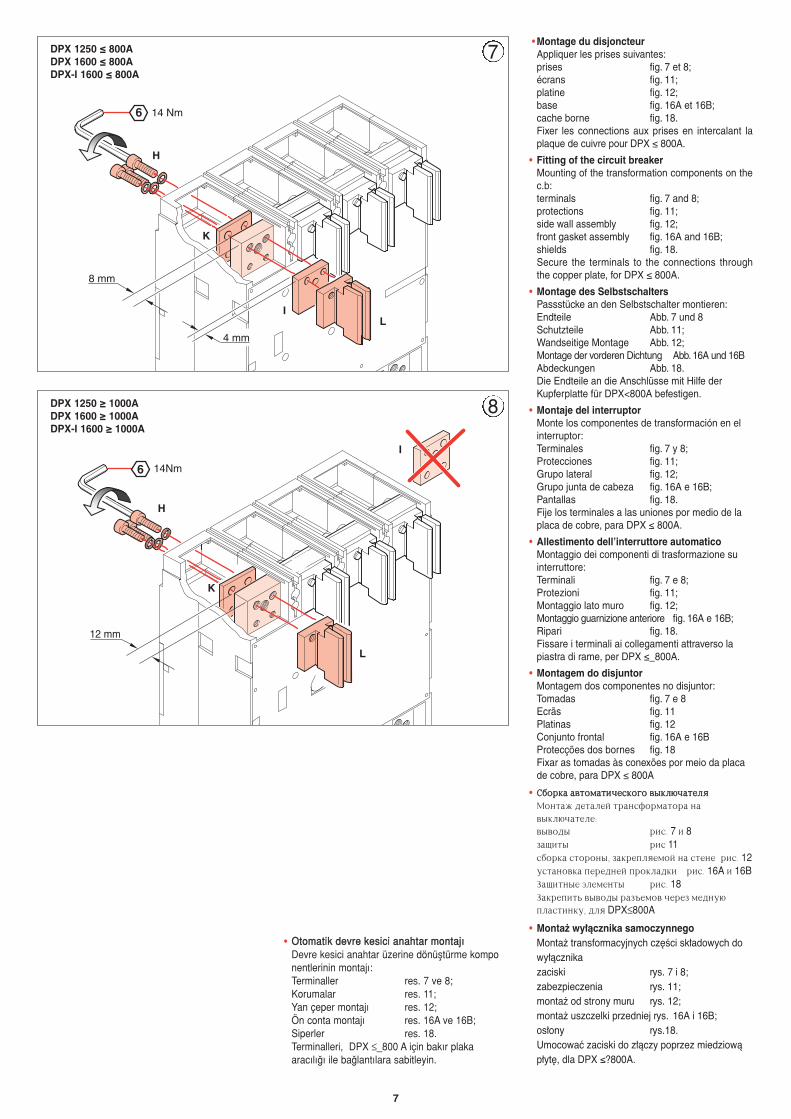
• Fixation de la partie fixeLa partie fixe peut être montée horizontalement ouverticalement (quelque soit le sens).
• Fixation of the baseThe base can be mounted in vertical andhorizontal position (both direction).
• Befestigung der BasisDie Basis kann sowohl vertikal als auch horizontal(in beiden Richtungen) montiert werden
• Fijación de la baseLa base se puede montar en posición vertical yhorizontal (en ambos sentidos).
• Fissaggio della baseLa base può essere montata in posizione verticaleed orizzontale (ambo le direzioni).
• Fixação da parte fixaA parte fixa pode ser montada horizontal ouverticalmente (em qualquer sentido)
• RRhhttggkkttyybbtt jjccyyjjddffyybbzzJcyjdfybt vj;tn ,snm ecnfyjdktyj ddthnbrfkmyjv b ujhbpjynfkmyjv gjkj;tybb ødj,jb[ yfghfdktybz[
• Umocowanie podstawyPodstawa mo˝e byç zamontowana w pozycjipionowej i poziomej (w obydwu kierunkach).
• TTaabbaann ssaabbiittlleemmeessiiTaban, dikey ve yatay pozisyonda (her iki yön) monte edilebilir.
5
814Nm
• Fixer la base sur son support.
• Secure the base to the support.
• Die Basis an die Halterung befestigen.
• Fije la base al soporte.
• Fissare la base al supporto.
• Fixar a base no suporte
• Pfabrcbhjdfnm jcyjdfybt yf jgjht7
• Umocowaç podstaw´ do podpory
• Tabanı deste¤e sabitleyin.
F
E
E
E
E
6
7
8 mm
4 mm
6 14 Nm
• Montage du disjoncteurAppliquer les prises suivantes:prises fig. 7 et 8;écrans fig. 11;platine fig. 12;base fig. 16A et 16B;cache borne fig. 18.Fixer les connections aux prises en intercalant laplaque de cuivre pour DPX ≤ 800A.
• Fitting of the circuit breakerMounting of the transformation components on thec.b:terminals fig. 7 and 8;protections fig. 11;side wall assembly fig. 12;front gasket assembly fig. 16A and 16B;shields fig. 18.Secure the terminals to the connections throughthe copper plate, for DPX ≤ 800A.
• Montage des SelbstschaltersPassstücke an den Selbstschalter montieren:Endteile Abb. 7 und 8 Schutzteile Abb. 11;Wandseitige Montage Abb. 12;Montage der vorderen Dichtung Abb. 16A und 16BAbdeckungen Abb. 18.Die Endteile an die Anschlüsse mit Hilfe derKupferplatte für DPX<800A befestigen.
• Montaje del interruptorMonte los componentes de transformación en elinterruptor:Terminales fig. 7 y 8;Protecciones fig. 11;Grupo lateral fig. 12;Grupo junta de cabeza fig. 16A e 16B;Pantallas fig. 18.Fije los terminales a las uniones por medio de laplaca de cobre, para DPX ≤ 800A.
• Allestimento dell’interruttore automaticoMontaggio dei componenti di trasformazione suinterruttore:Terminali fig. 7 e 8;Protezioni fig. 11;Montaggio lato muro fig. 12;Montaggio guarnizione anteriore fig. 16A e 16B;Ripari fig. 18.Fissare i terminali ai collegamenti attraverso lapiastra di rame, per DPX ≤_800A.
• Montagem do disjuntorMontagem dos componentes no disjuntor:Tomadas fig. 7 e 8Ecrãs fig. 11Platinas fig. 12Conjunto frontal fig. 16A e 16BProtecções dos bornes fig. 18Fixar as tomadas às conexões por meio da placade cobre, para DPX ≤ 800A
• CC,,jjhhrrff ffddnnjjvvffnnbbxxttccrrjjuujj ddssrrkk..xxffnnttkkzzVjynf; ltnfktq nhfycajhvfnjhf yfdsrk.xfntkt5dsdjls hbc7 7 b 8pfobns hbc 11c,jhrf cnjhjys6 pfrhtgkztvjq yf cntyt hbc7 12ecnfyjdrf gthtlytq ghjrkflrb hbc7 16A b 16BPfobnyst 'ktvtyns hbc7 18Pfrhtgbnm dsdjls hfp]tvjd xthtp vtlye.gkfcnbyre6 lkz DPX≤800A
• Monta˝ wy∏àcznika samoczynnegoMonta˝ transformacyjnych cz´Êci sk∏adowych dowy∏àcznikazaciski rys. 7 i 8;zabezpieczenia rys. 11;monta˝ od strony muru rys. 12;monta˝ uszczelki przedniej rys. 16A i 16B;os∏ony rys.18.Umocowaç zaciski do z∏àczy poprzez miedziowàp∏yt´, dla DPX ≤?800A.
• OOttoommaattiikk ddeevvrree kkeessiiccii aannaahhttaarr mmoonnttaajjııDevre kesici anahtar üzerine dönüfltürme komponentlerinin montajı:Terminaller res. 7 ve 8;Korumalar res. 11;Yan çeper montajı res. 12;Ön conta montajı res. 16A ve 16B;Siperler res. 18.Terminalleri, DPX ≤_800 A için bakır plaka aracılı¤ı ile ba¤lantılara sabitleyin.
14Nm
12 mm
6
H
K
IL
H
I
K
L
DPX 1250 ≤ 800ADPX 1600 ≤ 800ADPX-I 1600 ≤ 800A
DPX 1250 ≥ 1000ADPX 1600 ≥ 1000ADPX-I 1600 ≥ 1000A
7
8
8
AB
C
A BC
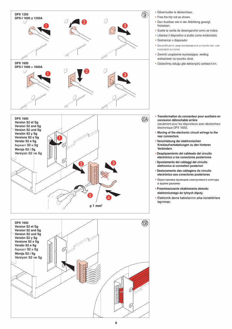
• Déverrouiller le déclencheur.
• Free the trip rod as shown.
• Den Auslöser wie in der Abbildung gezeigt,freisetzen.
• Suelte la varilla de desenganche como se indica.
• Liberare il dispositivo a scatto come evidenziato.
• Destrancar o disparador
• Dscdj,jlbnm pfotkrbdf.ottcz ecnhjqcndj6 rfrgjrfpfyj d c[tvt7
• Zwolniç urzàdzenie wyzwalajàce, wed∏ugwskazówek na rysunku obok.
• Gösterilmifl oldu¤u gibi deklanflörü serbest kılın.
• Transformation du connecteur pour auxiliaire enconnexion débrochable arrière(seulement pour les disjoncteurs avec déclencheurélectronique DPX 1600).
• Moving of the electronic circuit wirings to therear connectors
• Verschiebung der elektronischenKreislaufverkabelungen zu den hinterenVerbindern
• Desplazamiento del cableado del circuitoelectrónico a los conectores posteriores
• Spostamento dei cablaggi del circuitoelettronico ai connettori posteriori
• Deslocamento das cablagens do circuitoelectrónico aos conectores posteriores
• GGtthhttccnnffyyjjddrrff gghhjjddjjlljjdd ''kkttrrnnhhjjyyyyjjuujj rrjjyynneehhffdd ppffllyybbtt hhffpp]]ttvvss
• Przemieszczenie okablowania obwoduelektronicznego do tylnych z∏àczy.
• EElleekkttrroonniikk ddeevvrree kkaabblloollaarrıınnıınn aarrkkaa kkoonneekkttöörrlleerreettaaflflıınnmmaassıı
12
34
56
78
910
A
E D
B C
12
34
56
78
910
12
34
56
78
910
≤ 1 mm2
DPX 1250DPX-I 1600 ≤ 1250A
DPX 1600DPX-I 1600 = 1600A
DPX 1600Version S2 et SgVersion S2 and SgVersion S2 und SgVersión S2 y SgVersione S2 e SgVersão S2 e SgDDffhhbbffyynn SS22 bb SSggWersja S2 i SgVVeerrssiiyyoonn SS22 vvee SSgg
DPX 1600Version S2 et SgVersion S2 and SgVersion S2 und SgVersión S2 y SgVersione S2 e SgVersão S2 e SgDDffhhbbffyynn SS22 bb SSggWersja S2 i SgVVeerrssiiyyoonn SS22 vvee SSgg
9
10A
10B
9
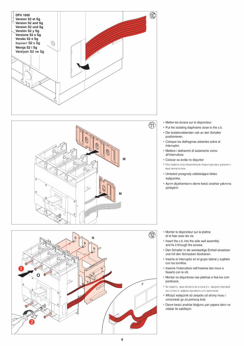
• Mettre les écrans sur le disjoncteur.
• Put the isolating diaphrams close to the c.b.
• Die Isolationsblenden nah an den Schalterpositionieren.
• Coloque los diafragmas aislantes sobre elinterruptor.
• Mettere i diaframmi di isolamento vicinoall’interruttore
• Colocar os ecrãs no disjuntor• Gjcnfdbnm bpjkzwbjyye. gthtujhjlre hzljv c
dsrk.xfntktv
• UmieÊciç przegrody oddzielajàce bliskowy∏àcznika.
• Ayrım diyaframlarını devre kesici anahtar yakınınayerlefltirin
A
B
• Monter le disjoncteur sur la platineet le fixer avec les vis.
• Insert the c.b. into the side wall assembly and fix it through the screws.
• Den Schalter in die wandseitige Einheit einsetzenund mit den Schrauben blockieren.
• Inserte el interruptor en el grupo lateral y sujételocon los tornillos.
• Inserire l’interruttore nell’insieme lato muro efissarlo con le viti.
• Montar os disjuntores nas platinas e fixá-los comparafusos.
• Dcnfdbnm dsrk.xfntkm d rj;e[6 pfrhtgkztvsqyf cntyt b pfabrcbhjdfnm tuj dbynfvb
• W∏o˝yç wy∏àcznik do zespo∏u od strony muru iumocowaç go za pomocà Êrub.
• Devre kesici anahtar blo¤unu yan çepere takın vevidalar ile sabitleyin.
M
N
O
M
10C
11
12
DPX 1600Version S2 et SgVersion S2 and SgVersion S2 und SgVersión S2 y SgVersione S2 e SgVersão S2 e SgDDffhhbbffyynn SS22 bb SSggWersja S2 i SgVVeerrssiiyyoonn SS22 vvee SSgg
10
B
A
P
Q
13
14A 14B
09819
CLACK
A
B
C
26399
26399
CLACK
CLACK
CLACK
A
B
C
GG
14B
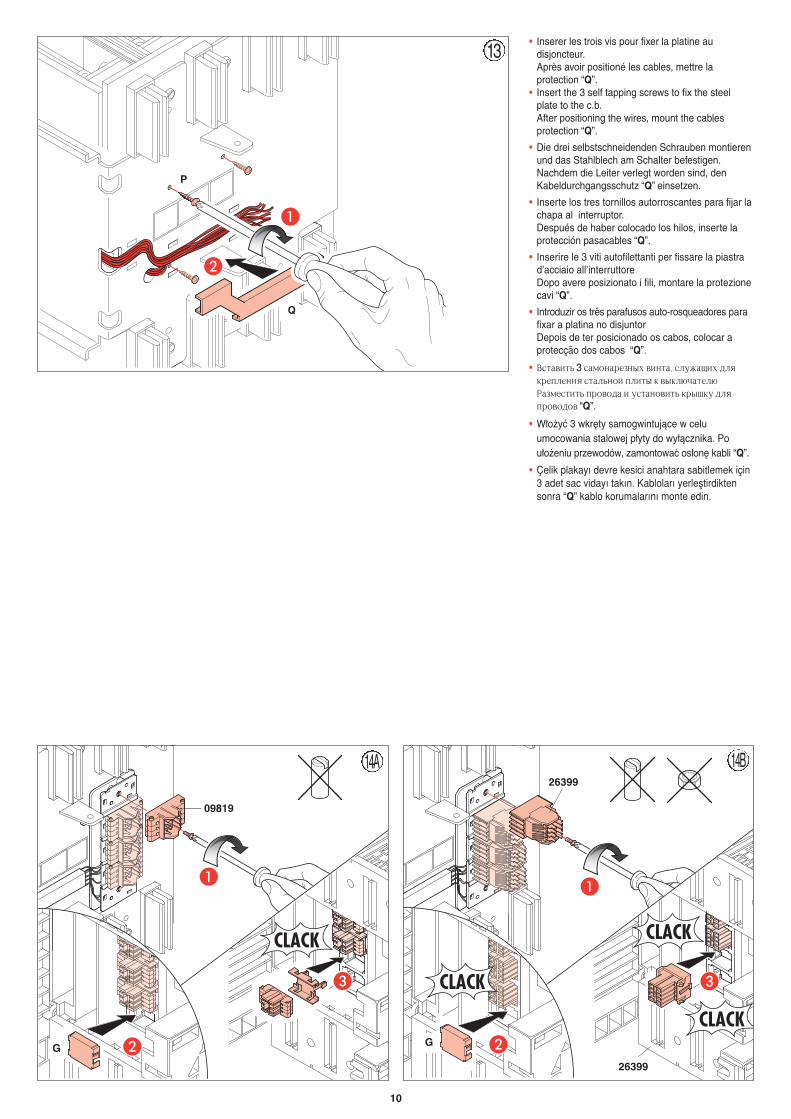
• Inserer les trois vis pour fixer la platine audisjoncteur.Après avoir positioné les cables, mettre laprotection “Q”.
• Insert the 3 self tapping screws to fix the steelplate to the c.b.After positioning the wires, mount the cablesprotection “Q”.
• Die drei selbstschneidenden Schrauben montierenund das Stahlblech am Schalter befestigen.Nachdem die Leiter verlegt worden sind, denKabeldurchgangsschutz “Q” einsetzen.
• Inserte los tres tornillos autorroscantes para fijar lachapa al interruptor.Después de haber colocado los hilos, inserte laprotección pasacables “Q”.
• Inserire le 3 viti autofilettanti per fissare la piastrad’acciaio all’interruttore Dopo avere posizionato i fili, montare la protezionecavi “Q”.
• Introduzir os três parafusos auto-rosqueadores parafixar a platina no disjuntorDepois de ter posicionado os cabos, colocar aprotecção dos cabos “Q”.
• Dcnfdbnm 3 cfvjyfhtpys[ dbynf6 cke;fob[ lkzrhtgktybz cnfkmyjq gkbns r dsrk.xfntk. Hfpvtcnbnm ghjdjlf b ecnfyjdbnm rhsire lkzghjdjljd “Q”.
• W∏o˝yç 3 wkr´ty samogwintujàce w celuumocowania stalowej p∏yty do wy∏àcznika. Pou∏o˝eniu przewodów, zamontowaç os∏on´ kabli “Q”.
• Çelik plakayı devre kesici anahtara sabitlemek için3 adet sac vidayı takın. Kabloları yerlefltirdiktensonra “Q” kablo korumalarını monte edin.
11
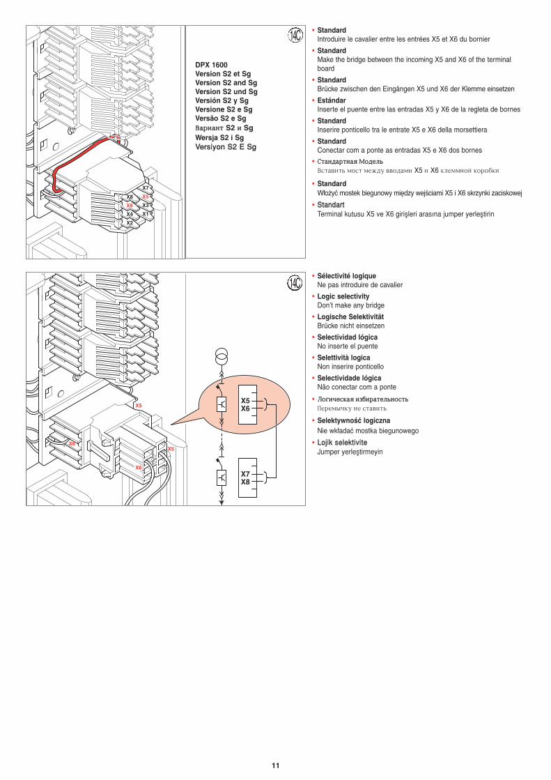
• StandardIntroduire le cavalier entre les entrées X5 et X6 du bornier
• StandardMake the bridge between the incoming X5 and X6 of the terminalboard
• Standard Brücke zwischen den Eingängen X5 und X6 der Klemme einsetzen
• EstándarInserte el puente entre las entradas X5 y X6 de la regleta de bornes
• StandardInserire ponticello tra le entrate X5 e X6 della morsettiera
• Standard Conectar com a ponte as entradas X5 e X6 dos bornes
• CCnnffyyllffhhnnyyffzz VVjjllttkkmmDcnfdbnm vjcn vt;le ddjlfvb X5 b X6 rktvvyjq rjhj,rb
• StandardW∏o˝yç mostek biegunowy mi´dzy wejÊciami X5 i X6 skrzynki zaciskowej
• SSttaannddaarrttTerminal kutusu X5 ve X6 giriflleri arasına jumper yerlefltirin
DPX 1600Version S2 et SgVersion S2 and SgVersion S2 und SgVersión S2 y SgVersione S2 e SgVersão S2 e SgDDffhhbbffyynn S2 bb SgWersja S2 i SgVVeerrssiiyyoonn SS22 EE SSgg
14C
14C
X2
X4
X6
X8
X1
X3
X5
X7
X7X8
X5X6
X6
X5
X6
X5
• Sélectivité logiqueNe pas introduire de cavalier
• Logic selectivityDon’t make any bridge
• Logische SelektivitätBrücke nicht einsetzen
• Selectividad lógicaNo inserte el puente
• Selettività logicaNon inserire ponticello
• Selectividade lógica Não conectar com a ponte
• KKjjuubbxxttccrrffzz bbpp,,bbhhffnnttkkmmyyjjccnnmmGthtvsxre yt cnfdbnm
• SelektywnoÊç logicznaNie wk∏adaç mostka biegunowego
• LLoojjiikk sseelleekkttiivviitteeJumper yerlefltirmeyin
X2
X4
X6
X8
X1
X3
X5
X7
X7X8
X5X6
X6
X5
X6
X5
12
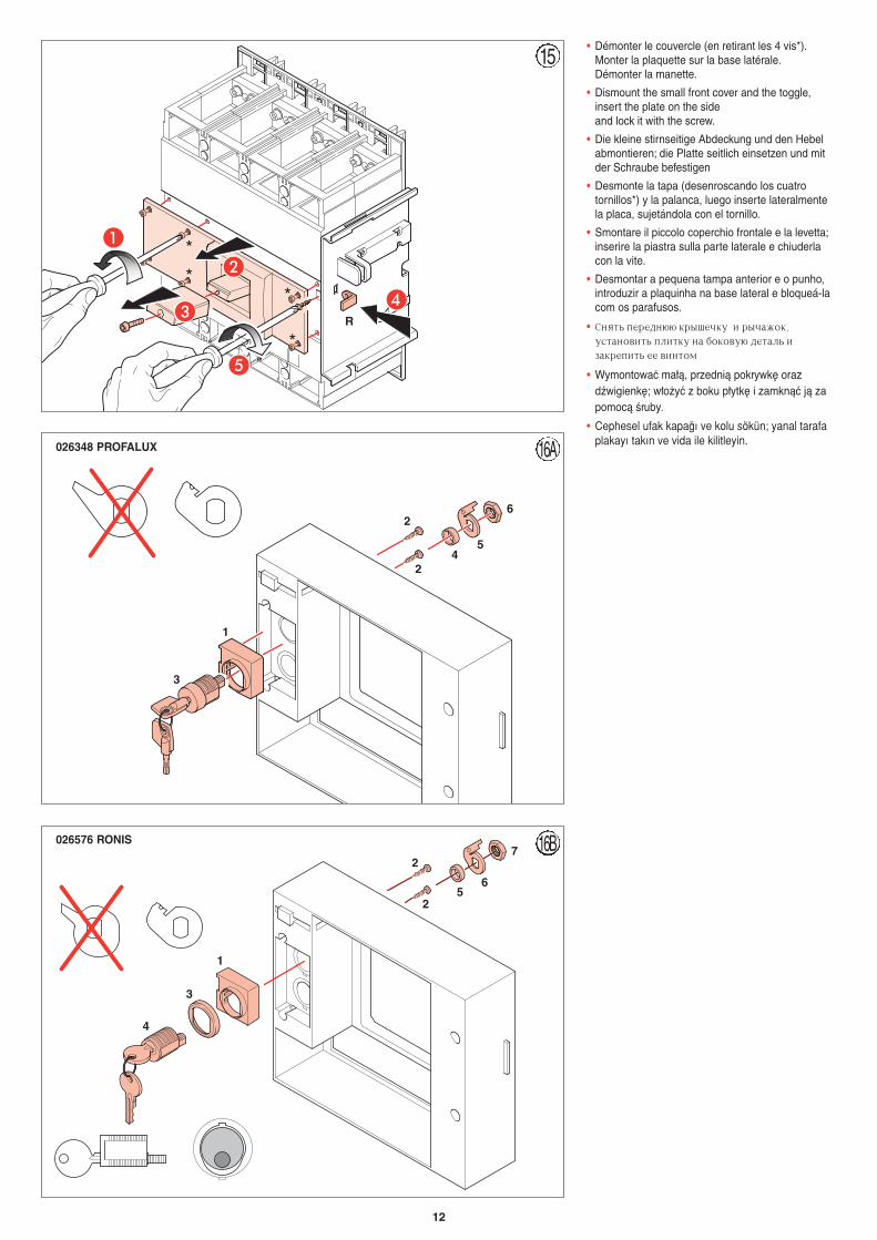
• Démonter le couvercle (en retirant les 4 vis*).Monter la plaquette sur la base latérale.Démonter la manette.
• Dismount the small front cover and the toggle,insert the plate on the side and lock it with the screw.
• Die kleine stirnseitige Abdeckung und den Hebelabmontieren; die Platte seitlich einsetzen und mitder Schraube befestigen
• Desmonte la tapa (desenroscando los cuatrotornillos*) y la palanca, luego inserte lateralmentela placa, sujetándola con el tornillo.
• Smontare il piccolo coperchio frontale e la levetta;inserire la piastra sulla parte laterale e chiuderlacon la vite.
• Desmontar a pequena tampa anterior e o punho,introduzir a plaquinha na base lateral e bloqueá-lacom os parafusos.
• Cyznm gthtly.. rhsitxre b hsxf;jr6ecnfyjdbnm gkbnre yf ,jrjde. ltnfkm bpfrhtgbnm tt dbynjv
• Wymontowaç ma∏à, przednià pokrywk´ orazdêwigienk´; w∏o˝yç z boku p∏ytk´ i zamknàç jà zapomocà Êruby.
• Cephesel ufak kapa¤ı ve kolu sökün; yanal tarafaplakayı takın ve vida ile kilitleyin.
*
**
*
A
B
DC
E
45
6
2
2
1
3
1
3
4
56
7
2
2
R
15
16A
16B
026348 PROFALUX
026576 RONIS
A
B
13
V
W
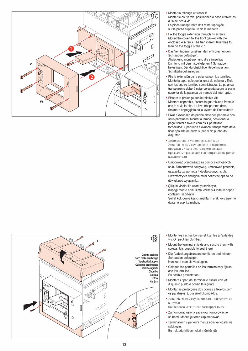
17• Monter la rallonge et visser la.
Monter le couvercle, positionner la base et fixer lesà l’aide des 4 vis.La piece transparente doit rester appuyée sur la partie superiéure de la manette.
• Fix the toggle extension through its screws.Mount the cover, fix the front gasket with theenclosed 4 screws. The transparent lever has tolean on the toggle of the c.b.
• Das Verlängerungsteil mit den entsprechendenSchrauben befestigen.Abdeckung montieren und die stirnseitigeDichtung mit den mitgelieferten 4 Schraubenbefestigen. Der durchsichtige Hebel muss amSchalterhebel anliegen.
• Fije la extensión de la palanca con los tornillos.Monte la tapa, coloque la junta de cabeza y fíjelacon los cuatro tornillos suministrados. La palancatransparente deberá estar colocada sobre la partesuperior de la palanca de mando del interruptor.
• Fissare la prolunga con le relative viti.Montare coperchio, fissare la guarnizione frontalecon le 4 viti fornite. La leva trasparente deverimanere appoggiata sulla levetta dell’interruttore
• Fixar a extensão do punho alavanca por meio dosseus parafusos. Montar a tampa, posicionar apeça frontal e fixá-la com os 4 parafusosfornecidos. A pequena alavanca transparente deveficar apoiada na parte superior do punho dodisjuntor.
• Pfabrcbhjdfnm elkbybntkm dbynfvb7Ecnfyjdbnm rhsire6 pfrhtgbnm gthtly..ghjrkflre 4 rjvgktrne.obvb dbynfvb7Ghjphfxysq hsxfu ljk;ty jgbhfnmcz yf hsxfudsrk.xfntkz7
• Umocowaç przed∏u˝acz za pomocà odnoÊnychÊrub. Zamontowaç pokrywk´, umocowaç przedniàuszczelk´ za pomocà 4 dostarczonych Êrub.Przezroczysta dêwignia musi pozostaç oparta nadêwigience wy∏àcznika.
• fiIliflkin vidalar ile uzantıyı sabitleyin.Kapa¤ı monte edin, ikmal edilmifl 4 vida ilecephe contasını sabitleyin.fieffaf kol, devre kesici anahtarın ufak kolu üzerinedayalı olarak kalmalıdır.
T
S
U
Calotte scelléesDon’t make any bridge
Versiegelte kappenCubiertas precintadas
Calotte sigillateChumbo
ggkkjjvv<<ffO∏ów
KKuurrfifiuunn
18• Monter les caches bornes et fixer les à l’aide des
vis. On peut les plomber.
• Mount the terminal shields and secure them withscrews. It is possible to seal them.
• Die Abdeckungsblenden montieren und mit denSchrauben befestigen.Nun kann man sie versiegeln.
• Coloque las pantallas de los terminales y fíjelascon los tornillos.Es posible precintarlas.
• Montare i ripari dei terminali e fissarli con viti.A questo punto è possibile sigillarli.
• Montar as protecções dos bornes e fixá-los comos parafusos. É possível chumbá-los.
• Ecnfyjdbnm rhsire yf dsdjls b pfrhtgbnm ttdbynfvb7Gjckt 'njuj vj;tnt pfgkjv,bhjdfnm b[7
• Zamontowaç os∏ony zacisków i umocowaç jeÊrubami. Mo˝na je teraz zaplombowaç.
• Terminallerin siperlerini monte edin ve vidalar ilesabitleyin.Bu noktada kilitlenmeleri mümkündür.
14
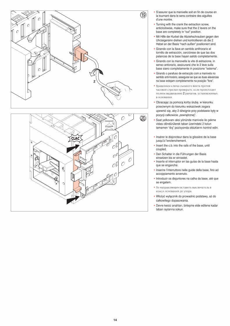
• S’assurer que la manivelle soit en fin de course enla tournant dans le sens contraire des aiguillesd’une montre.
• Turning with the crank the extraction screw,anticlockwise, make sure that the 2 levers on thebase are completely in “out” position.
• Mit Hilfe der Kurbel die Abziehschrauben gegen denUhrzeigersinn drehen und kontrollieren ob die 2Hebel an der Basis “nach außen” positioniert sind.
• Girando con la llave en sentido antihorario eltornillo de extracción, cerciórese de que las dospalancas de la base hayan salido completamente.
• Girando con la manovella la vite di estrazione, insenso antiorario, assicurarsi che le 2 leve sullabase siano completamente in posizione "esterna".
• Girando o parafuso de extracção com a manivela nosentido anti-horário, assegurar-se que as duas alavancasna base estejam completamente na posição "fora".
• Dhfotybtv rk.xf c]tvyjuj dbynf ghjnbdxfcjdjq cnhtkrb ghjdthmnt6 tckb ghjbc[jlbngjkyjt dsldb;tybt 2 hsxfujd6 ecnfyjdktyys[d jcyjdfybb7
• Obracajàc za pomocà korby Êrub´, w kierunkuprzeciwnym do kierunku wskazówek zegaraupewniç si´, aby 2 dêwignie przy podstawie by∏y wpozycji ca∏kowicie „zewn´trznej”.
• Saat yelkovanı aksi yönünde manivela ile çekmevidası döndürülerek taban üzerindeki 2 koluntamamen “dıfl” pozisyonda olduklarını kontrol edin.
Z
19
CLAC • Insérer le disjoncteur dans la glissière de la basejusqu’à l’enclenchement.
• Insert the c.b. into the rails of the base, untilcoupled.
• Den Schalter in die Führungen der Basiseinsetzen bis er einrastet.
• Inserte el interruptor en las guías de la base hastaque se enganche.
• Inserire l’interruttore nelle guide della base, fino adaccoppiamento avvenuto.
• Introduzir os disjuntores na calha da base, até quese engatem.
• Gj yfghfdkz.obv dcnfdbnm dsrk.xfntkm drj;e[ jcyjdfybz lj egjhf7
• W∏o˝yç wy∏àcznik do prowadnic podstawy, a˝ doca∏kowitego dopasowania.
• Devre kesici anahtarı, birleflme elde edilene kadartaban raylarına sokun.
20
15
Rouge
Jaune
21
22
Pos. INSEREPLUGGEDPos. EINGESETZTPos. CONECTADOPos. INSERITOPos. INSERIDOGGjjkkjj;;ttyybbtt DDRRKK>>XXTTYYJJ
Poz. W¸O˝ONYPPoozz.. TTAAKKIILLII
Pos. EXTRAIT ESSAITEST-PositionPos. HERAUSGENOMMEN VERSUCHSWEISEPos. EXTRAÍDO DE PRUEBAPos. ESTRATTO DI PROVAPos. EXTRACTO DE PROVAGGjjkkjj;;ttyybbtt BBPPDDKKTTXXTTYYJJ NNTTCCNNBBHHJJDDFFYYBBTT
Poz. WYCIÑGNI¢TY PRÓBNYPPoozz.. ÇÇEEKKfifiIILLfifiII DDEENNEEMMEE
RougeRedRotRojoRossoVermelhaRRhhffccyyssqq
CzerwonyKKıırrmmıızzıı
JauneYellowGelbAmarilloGialloAmarelo˚ó∏tySSaarrıı::ttkknnssqq
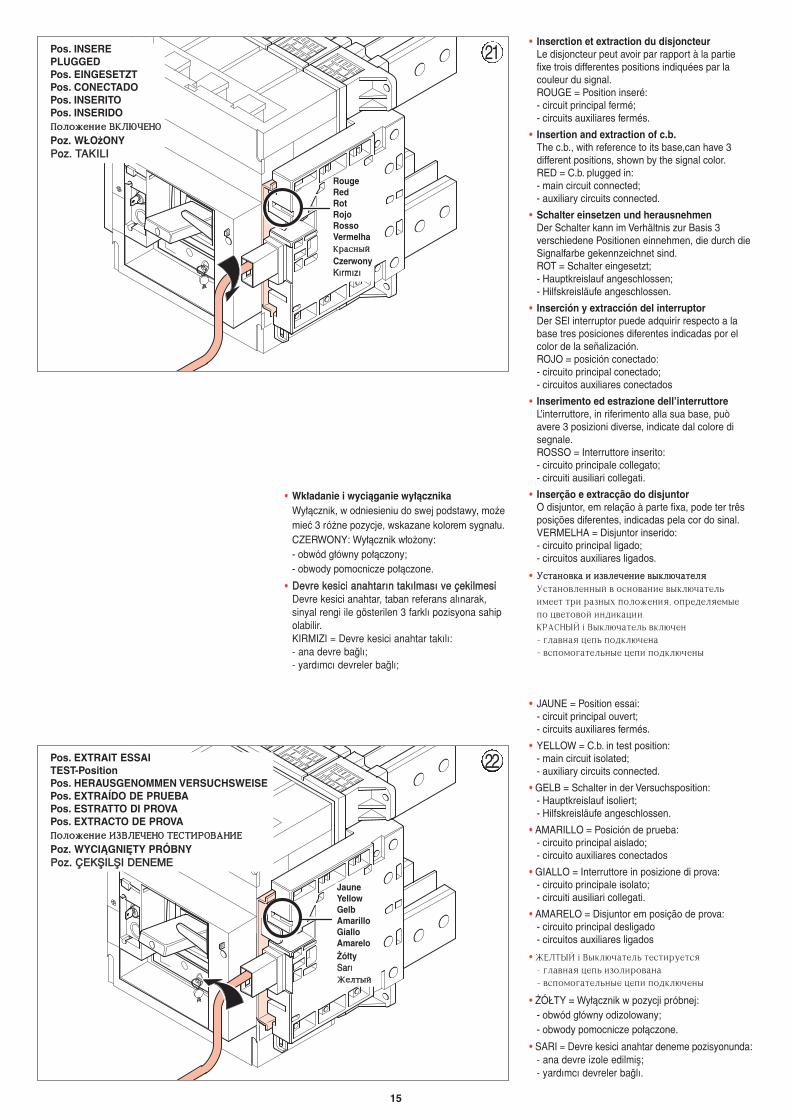
• JAUNE = Position essai:- circuit principal ouvert;- circuits auxiliares fermés.
• YELLOW = C.b. in test position:- main circuit isolated;- auxiliary circuits connected.
• GELB = Schalter in der Versuchsposition:- Hauptkreislauf isoliert;- Hilfskreisläufe angeschlossen.
• AMARILLO = Posición de prueba:- circuito principal aislado;- circuito auxiliares conectados
• GIALLO = Interruttore in posizione di prova:- circuito principale isolato;- circuiti ausiliari collegati.
• AMARELO = Disjuntor em posição de prova:- circuito principal desligado- circuitos auxiliares ligados
• :TKNSQ = Dsrk.xfntkm ntcnbhetncz - ukfdyfz wtgm bpjkbhjdfyf- dcgjvjufntkmyst wtgb gjlrk.xtys
• ˚Ó¸TY = Wy∏àcznik w pozycji próbnej:- obwód g∏ówny odizolowany;- obwody pomocnicze po∏àczone.
• SARI = Devre kesici anahtar deneme pozisyonunda:- ana devre izole edilmifl;- yardımcı devreler ba¤lı.
• Inserction et extraction du disjoncteurLe disjoncteur peut avoir par rapport à la partiefixe trois differentes positions indiquées par lacouleur du signal.ROUGE = Position inseré:- circuit principal fermé;- circuits auxiliares fermés.
• Insertion and extraction of c.b.The c.b., with reference to its base,can have 3different positions, shown by the signal color.RED = C.b. plugged in:- main circuit connected;- auxiliary circuits connected.
• Schalter einsetzen und herausnehmenDer Schalter kann im Verhältnis zur Basis 3verschiedene Positionen einnehmen, die durch dieSignalfarbe gekennzeichnet sind.ROT = Schalter eingesetzt;- Hauptkreislauf angeschlossen;- Hilfskreisläufe angeschlossen.
• Inserción y extracción del interruptorDer SEl interruptor puede adquirir respecto a labase tres posiciones diferentes indicadas por elcolor de la señalización.ROJO = posición conectado:- circuito principal conectado;- circuitos auxiliares conectados
• Inserimento ed estrazione dell’interruttore L’interruttore, in riferimento alla sua base, puòavere 3 posizioni diverse, indicate dal colore disegnale.ROSSO = Interruttore inserito:- circuito principale collegato;- circuiti ausiliari collegati.
• Inserção e extracção do disjuntorO disjuntor, em relação à parte fixa, pode ter trêsposições diferentes, indicadas pela cor do sinal.VERMELHA = Disjuntor inserido:- circuito principal ligado;- circuitos auxiliares ligados.
• EEccnnffyyjjddrrff bb bbppddkkttxxttyybbtt ddssrrkk..xxffnnttkkzzEcnfyjdktyysq d jcyjdfybt dsrk.xfntkmbvttn nhb hfpys[ gjkj;tybz6 jghtltkztvstgj wdtnjdjq bylbrfwbb7 RHFCYSQ = Dsrk.xfntkm drk.xty- ukfdyfz wtgm gjlrk.xtyf- dcgjvjufntkmyst wtgb gjlrk.xtys
• Wk∏adanie i wyciàganie wy∏àcznikaWy∏àcznik, w odniesieniu do swej podstawy, mo˝emieç 3 ró˝ne pozycje, wskazane kolorem sygna∏u. CZERWONY: Wy∏àcznik w∏o˝ony:- obwód g∏ówny po∏àczony;- obwody pomocnicze po∏àczone.
• DDeevvrree kkeessiiccii aannaahhttaarrıınn ttaakkııllmmaassıı vvee ççeekkiillmmeessiiDevre kesici anahtar, taban referans alınarak, sinyal rengi ile gösterilen 3 farklı pozisyona sahip olabilir. KIRMIZI = Devre kesici anahtar takılı:- ana devre ba¤lı;- yardımcı devreler ba¤lı;
16
Vert
A
B
24B24A
23Pos. EXTRAITISOLATED-PositionPos. HERAUSGENOMMENPos. EXTRAÍDOPos. ESTRATTOPos. EXTRACTOGGjjkkjj;;ttyybbtt BBPPDDKKTTXXTTYYJJ
Poz. WYCI≈GNI¢TYPPoozz.. ÇÇEEKKfifiIILLfifiII
VertGreenGrünVerdeVerdeVerdePPttkkttyyssqqZielonyYYeeflflflfliill
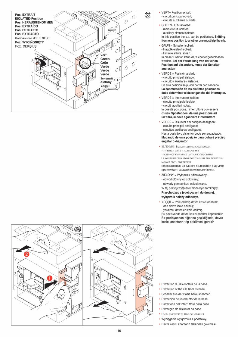
• VERT= Position extrait:- circuit principal ouvert;- circuits auxiliares ouverts.
• GREEN= C.b. isolated:- main circuit isolated;- auxiliary circuits isolated.In this position the c.b. can be padlocked. Shiftingfrom one position to another one must trip the c.b.
• GRÜN = Schalter isoliert:- Hauptkreislauf isoliert;- Hilfskreisläufe isoliert.In dieser Position kann der Schalter geschlossenwerden. Bei der Verstellung von der einenPosition auf die andere, muss der Schalterausrasten
• VERDE = Posición aislado- circuito principal aislado;- circuitos auxiliares aislados.En esta posición se puede cerrar con candado.La conmutación de las distintas posicionesdebe determinar el desenganche del interruptor.
• VERDE = Interruttore isolato:- circuito principale isolato;- circuiti ausiliari isolati.In questa posizione, l’interruttore può esserechiuso. Spostandosi da una posizione adun’altra, si deve sganciare l’interruttore
• VERDE = Disjuntor em posição desligada:- circuito principal desligado;- circuitos auxiliares desligados.Nesta posição o disjuntor pode ser encadeado.Mudando de uma posição para outra é precisoengatar o disjuntor
• PTKTYSQ = Dsrk.xfntkm bpjkbhjdfy- ukfdyfz wtgm bpjkbhjdfyf- dcgjvjufntkmyst wtgb bpjkbhjdfysYf[jlzobqcz d 'njv gjkj;tybb dsrk.xfntkmvj;tn ,snm dsrk.xty7GGtthhttvvttoottyybbttvv bbpp jjllyyjjuujj ggjjkkjj;;ttyybbzz dd llhheeuujjttgghhjjbbcc[[jjllbbnn hhffccwwttggkkttyybbtt ddssrrkk..xxffnnttkkzz77
• ZIELONY = Wy∏àcznik odizolowany:- obwód g∏ówny odizolowany;- obwody pomocnicze odizolowane.W tej pozycji wy∏àcznik mo˝e byç zamkni´ty.Przechodzàc z jedej pozycji do drugiej,wy∏àcznik nale˝y odhaczyç.
• YEfifiIL = izole edilmifl devre kesici anahtar:- ana devre izole edilmifl;- yardımcı devreler izole edilmifl.Bu pozisyonda devre kesici anahtar kapatılabilir. BBiirr ppoozziissyyoonnddaann ddii¤¤eerriinnee ggeeççiillddii¤¤iinnddee,, ddeevvrree kkeessiiccii aannaahhttaarrıınn ttrriipp eettttiirriillmmeessii ggeerreekkiirr
• Extraction du disjoncteur de la base.
• Extraction of the c.b. from its base.
• Schalter aus der Basis herausnehmen.
• Extracción del interruptor de la base.
• Estrazione dell’interruttore dalla base.
• Extracção do disjuntor da base
• C]tv dsrk.xfntkz c jcyjdfybz
• Wyciàganie wy∏àcznika z podstawy.
• Devre kesici anahtarın tabandan çekilmesi.
17
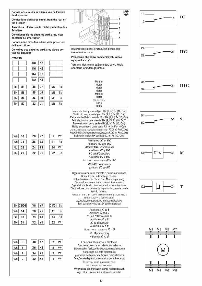
Connexions circuits auxiliares vue de l’arrièredu disjoncteur
Connections auxiliares circuit from the rear offthe breaker
Anschluss Hilfskreisläufe, Sicht von hinten desSchalters
Conexiones de los circuitos auxiliares, vistaposterior del interruptorl
Connessione circuiti ausiliari, vista posterioredell’interruttore
Conexões dos circuitos auxiliares vistas portrás do disjuntor
GGjjllrrkk..xxttyybbtt ddccggjjvvjjuuffnnttkkmmyyss[[ wwttggttqq66 ddbbllddssrrkk..xxffnnttkkzz ccppffllbb
Po∏àczenie obwodów pomocniczych, widokwy∏àcznika z ty∏u
YYaarrddıımmccıı ddeevvrreelleerriinn bbaa¤¤llaannmmaassıı,, ddeevvrree kkeessiicciiaannaahhttaarrıınn aarrkkaaddaann ggöörrüünnttüüssüü
026399
14
1211
24
2221
IC
IIC
D2 MD1U <
C2 TC1
54
5251 S
34
3431 IIIC
Auxiliaires IIC et IIICAuxiliary IIC and IIIC
IIC und IIIC Hilfskreisläufe Auxiliares IIC y IIICIIC ed IIIC ausiliare Auxiliares IIC e IIIC
Dcgjvjufntkmyst IIIICC b IIIIIICCIIC i IIIC pomocniczyyardımcı IIIICC ve IIIIIICC
Auxiliaires IC et SAuxiliary IC and S
IC und S HilfskreisläufeAuxiliares IC y SIC ed S ausiliare Auxiliares IC e S
Dcgjvjufntkmyst IICC b SSIC i S pomocniczyyardımcı IICC ve SS
Fonctions déclencheur éléctriqueFunctions overcurrent electronic release
Elektronischer Auslöser der ÜberspannungsfunktionenFunciones del relé electrónico
Sganciatore elettronico delle funzioni di sovratensione.Funções de disparador electrónico por sobrecarga.
"ktrnhjyysq hfcwtgbntkmvfrcbvfkmyjuj njrf
Wyzwalacz elektroniczny funkcji nadpràdowychAflırı akım ifllevlerinin elektronik salıcıları
Sganciatori a lancio di corrente o di minima tensioneShunt trip or undervoltage release.
Schnellauslöser für Strom oder Mindestspannung.Disparadores de corriente o de mínima tensión.
Sganciatori a lancio di corrente o di minima tensione.Disparadores com bobina de impulso de corrente ou de
tensão mínima.Hfcwtgbntkm c ienjdjq rfneirjq bkb hfcwtgbntkm
vbybvfkmyjuj yfghz;tybzWyzwalacze nadpràdowe lub podnapi´ciowe.
fiönt salıcıları veya düflük gerilim salıcıları
Relais electronique serial port RX (9, In) Fx (10, Out)Electronic relays: serial port RX (9, In) Fx (10, Out)
Elektronische Relais: serieller Port RX (9, In) Fx (10, Out)Relé electrónico: puerto serial RX (9, IN) Fx (10, OUT)
Relè elettronici: porta seriale RX (9, In) Fx (10, Out)Relés electrónicos: porta serial RX (9, In) Fx (10,Out)
"ktrnhjyyst htkt5 gjcktljdfntkmysq gjhn RX (9, In) Fx (10, Out)Przekaêniki elektroniczne: bramka szeregowa RX (9, In) Fx (10, Out)
Elektronik röleler: RX seri kapı (9, In) Fx (10, Out)
MoteurMotorMotorMotorMotoreMotor
LdbufntkmSilnikMotor
K
J
ZY
X
25
J8 J7
J6 J5
J4 J3
J2 J1
Z8 Z7
Z6 Z5
Z4 Z3
Z2 Z1
Y8 Y7
Y6 Y5
Y4 Y3
Y2 Y1
X8 X7
X6 X5
X4 X3
X2 X1
31 Bk
24 Wh
22 Rd
C1/D1 Bk
11 Bk
54 Rd
52 Wh
7
5
3
1
Wh 34
Rd 32
Bk 21
Bk C2/D2
Wh 14
Rd 12
Bk 51
8
6
4
2
Wh
Wh
Wh
Wh
Wh 10
K8 K7
K6 K5
K4 K3
K2 K1
Bk M2
Bk M4
Bk M6
Bk M8 M7 Bk
M5 Bk
M3 Bk
M1 Bk
9 Wh
Wh
Wh
Wh
Wh
M1 M3 M5 M7
M
M2 M4 M6 M8
J6 J5
J4 J3
J2 J1
Z6 Z5
Z4 Z3
Z2 Z1
Y6 Y5
Y4 Y3
Y2 Y1
X6 X5
X4 X3
X2 X1
14 Wh
12 Rd
54 Rd
52 Wh
M7 Bk
M5
M3
M1
Bk 11
Bk C2/D2
Bk 51
Bk M8
M6
M4
M2
Bk
Bk
Bk
K6 K5
K4 K3
K2 K1
Bk 21
Rd 32
Wh 34 31 Bk
24 Wh
22 Rd
Bk
Bk
Bk
C1/D1 Bk
18
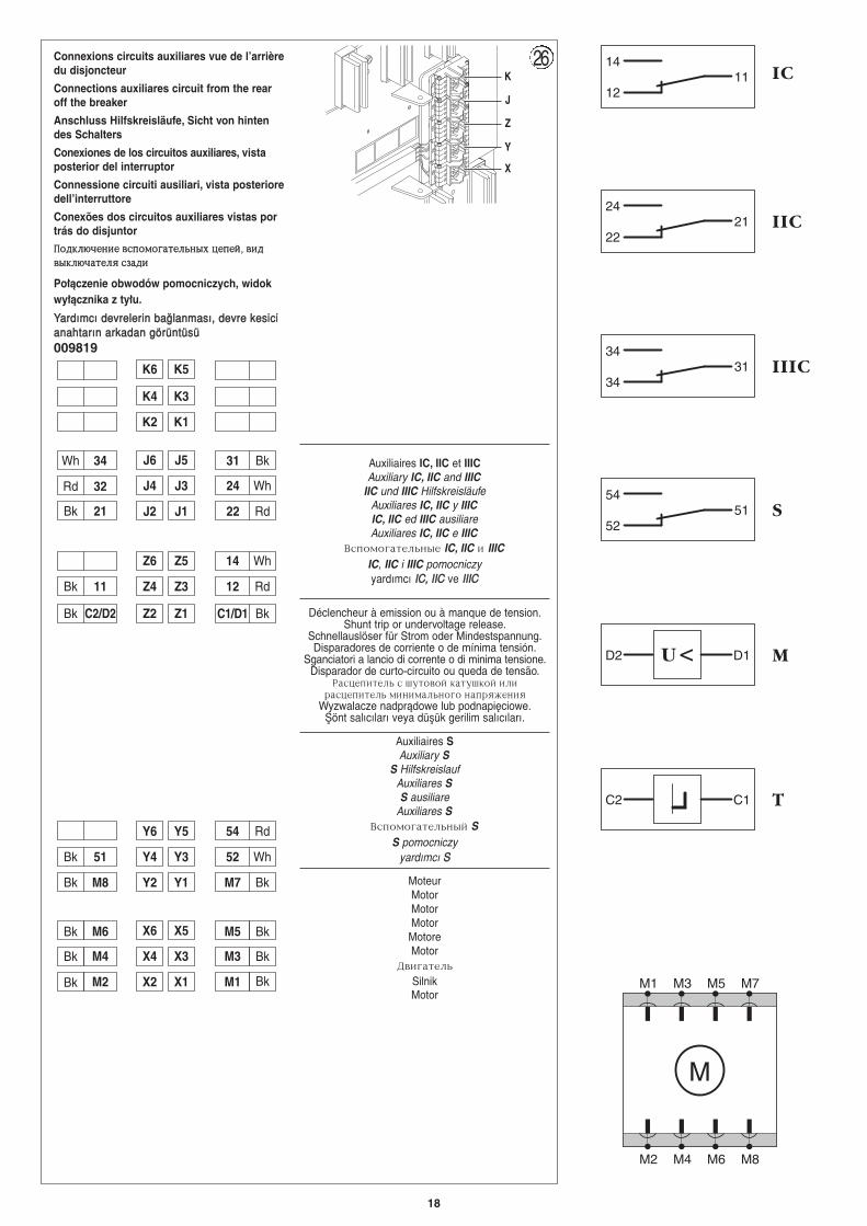
Connexions circuits auxiliares vue de l’arrièredu disjoncteur
Connections auxiliares circuit from the rearoff the breaker
Anschluss Hilfskreisläufe, Sicht von hintendes Schalters
Conexiones de los circuitos auxiliares, vistaposterior del interruptor
Connessione circuiti ausiliari, vista posterioredell’interruttore
Conexões dos circuitos auxiliares vistas portrás do disjuntor
GGjjllrrkk..xxttyybbtt ddccggjjvvjjuuffnnttkkmmyyss[[ wwttggttqq66 ddbbllddssrrkk..xxffnnttkkzz ccppffllbb
Po∏àczenie obwodów pomocniczych, widokwy∏àcznika z ty∏u.
YYaarrddıımmccıı ddeevvrreelleerriinn bbaa¤¤llaannmmaassıı,, ddeevvrree kkeessiicciiaannaahhttaarrıınn aarrkkaaddaann ggöörrüünnttüüssüü009819
Auxiliaires IC, IIC et IIICAuxiliary IC, IIC and IIIC
IIC und IIIC HilfskreisläufeAuxiliares IC, IIC y IIICIC, IIC ed IIIC ausiliareAuxiliares IC, IIC e IIIC
Dcgjvjufntkmyst IC, IIC b IIICIC, IIC i IIIC pomocniczyyardımcı IICC,, IIIICC ve IIIIIICC
Auxiliaires SAuxiliary S
S Hilfskreislauf Auxiliares SS ausiliare
Auxiliares SDcgjvjufntkmysq S
S pomocniczy yardımcı SS
MoteurMotorMotorMotorMotoreMotor
Ldbufntkm
SilnikMotor
Déclencheur à emission ou à manque de tension.Shunt trip or undervoltage release.
Schnellauslöser für Strom oder Mindestspannung.Disparadores de corriente o de mínima tensión.
Sganciatori a lancio di corrente o di minima tensione.Disparador de curto-circuito ou queda de tensão.
Hfcwtgbntkm c ienjdjq rfneirjq bkbhfcwtgbntkm vbybvfkmyjuj yfghz;tybz
Wyzwalacze nadpràdowe lub podnapi´ciowe.fiönt salıcıları veya düflük gerilim salıcıları.
K
J
Z
Y
X
26
J6 J5
J4 J3
J2 J1
Z6 Z5
Z4 Z3
Z2 Z1
Y6 Y5
Y4 Y3
Y2 Y1
X6 X5
X4 X3
X2 X1
14 Wh
12 Rd
54 Rd
52 Wh
M7 Bk
M5
M3
M1
Bk 11
Bk C2/D2
Bk 51
Bk M8
M6
M4
M2
Bk
Bk
Bk
K6 K5
K4 K3
K2 K1
Bk 21
Rd 32
Wh 34 31 Bk
24 Wh
22 Rd
Bk
Bk
Bk
C1/D1 Bk
J6 J5
J4 J3
J2 J1
Z6 Z5
Z4 Z3
Z2 Z1
Y6 Y5
Y4 Y3
Y2 Y1
X6 X5
X4 X3
X2 X1
14 Wh
12 Rd
54 Rd
52 Wh
M7 Bk
M5
M3
M1
Bk 11
Bk C2/D2
Bk 51
Bk M8
M6
M4
M2
Bk
Bk
Bk
K6 K5
K4 K3
K2 K1
Bk 21
Rd 32
Wh 34 31 Bk
24 Wh
22 Rd
Bk
Bk
Bk
C1/D1 BkJ6 J5
J4 J3
J2 J1
Z6 Z5
Z4 Z3
Z2 Z1
Y6 Y5
Y4 Y3
Y2 Y1
X6 X5
X4 X3
X2 X1
14 Wh
12 Rd
54 Rd
52 Wh
M7 Bk
M5
M3
M1
Bk 11
Bk C2/D2
Bk 51
Bk M8
M6
M4
M2
Bk
Bk
Bk
K6 K5
K4 K3
K2 K1
Bk 21
Rd 32
Wh 34 31 Bk
24 Wh
22 Rd
Bk
Bk
Bk
C1/D1 Bk
J6 J5
J4 J3
J2 J1
Z6 Z5
Z4 Z3
Z2 Z1
Y6 Y5
Y4 Y3
Y2 Y1
X6 X5
X4 X3
X2 X1
14 Wh
12 Rd
54 Rd
52 Wh
M7 Bk
M5
M3
M1
Bk 11
Bk C2/D2
Bk 51
Bk M8
M6
M4
M2
Bk
Bk
Bk
K6 K5
K4 K3
K2 K1
Bk 21
Rd 32
Wh 34 31 Bk
24 Wh
22 Rd
Bk
Bk
Bk
C1/D1 Bk
14
1211
24
2221
IC
IIC
D2 MD1U <
C2 TC1
54
5251 S
34
3431 IIIC
M1 M3 M5 M7
M
M2 M4 M6 M8
19
30.2215.6107.8
465579
187.
5 XX
Y
Y
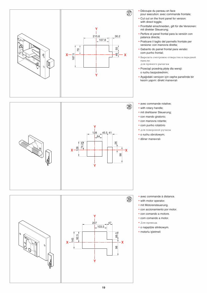
• Découpe du paneau en face pour execution: avec commande frontale;
• Cut out on the front panel for version:with direct toggle;
• Fronttafel einschneiden, gilt für die Versionen:mit direkter Steuerung;
• Perfore el panel frontal para la versión conpalanca directa;
• Praticare il taglio del pannello frontale perversione: con manovra diretta;
• Gabarito do painel frontal para versão:com punho frontal;
• Dshtpfnm cvjnhjdjt jndthcnbt d gthtlytqgfytkb5lkz ghzvjuj hsxfuf;
• Przeciàç przednià p∏yt´ dla wersji:o ruchu bezpoÊrednim;
• Afla¤ıdaki versiyon için cephe panelinde birkesim yapım: direkt manevralı
45.512864
26
74.2
5
128
XX
Y
Y
41
98
• avec commande rotative;
• with rotary handle;
• mit drehbarer Steuerung;
• con mando giratorio;
• con manovra rotante;
• com punho rotatório
• lkz gjdjhjyjq hexrb;
• o ruchu obrotowym;
• döner manevralı
66.5
47207103.5
98
92.5
145
XX
Y
Y
• avec commande à distance.
• with motor operator.
• mit Motorensteuerung.
• con accionamiento por motor.
• con comando a motore.
• com comando a motor.
• Lkz ghbdjlf7
• o nap´dzie silnikowym.
• motorlu iflletmeli
27
28
29
20
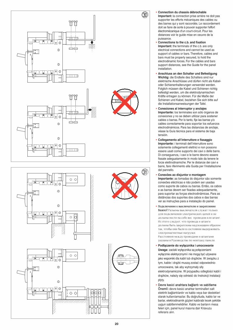
• Connection du chassis débrochable Important: la connection prise arriére ne doit passupporter les efforts mécaniques des cables oudes barres qui y sont raccordés. Le raccordementdoit se faire de sorte à pouvoir supporter l'effortélectromécanique d'un court-circuit. Pour lesdistances voir le guide mise en oeuvre de lapuissance.
• Connections to the c.b. and fixationImportant: the terminals of the c.b. are onlyelectrical connections and cannot be used assupport of cables or bars. Therefore, cables andbars must be properly secured, to hold theelectrodinamic forces. For the cables and barssupport distances, see the Guide for the panelinstallation.
• Anschluss an den Schalter und BefestigungWichtig: die Endteile des Schalters sind nurelektrische Anschlüsse und dürfen nicht als Kabel-oder Schienenhalterungen verwendet werden.Folglich müssen die Kabel und Schienen richtigbefestigt werden, um die elektrodynamischenKräfte ertragen zu können. Für die Maße derSchienen und Kabel, beziehen Sie sich bitte aufdie Installationsanweisungen der Tafel.
• Conexiones al interruptor y anclajesImportante: los terminales son sólo órganos deconexiones y no se deben utilizar para sostenercables o barras. Por lo tanto, fije las barras y/ocables correctamente para soportar los esfuerzoselectrodinámicos. Para las distancias de anclaje,véase la Guía técnica para el sistema de bajatensión.
• Collegamento all’interruttore e fissaggioImportante: i terminali dell’interruttore sonosolamente collegamenti elettrici e non possonoessere usati come supporto dei cavi o delle barre.Di conseguenza, i cavi e le barre devono esserefissate adeguatamente in modo tale da tenere leforze elettrodinamiche. Per le distanze dei cavi ebarre, fare riferimento alla Guida per l'installazionedel pannello.
• Conexões ao disjuntor e montagemImportante: as tomadas do disjuntor são somenteconexões eléctricas e não podem ser usadascomo suporte de cabos ou barras. Então, os cabose as barras devem ser fixadas adequadamente,para suportar as forças electrodinâmicas. Para asdistâncias dos suportes dos cabos e das barrasver as instruções para a instalação do painel.
• GGjjllrrkk..xxttyybbtt rr ddssrrkk..xxffnnttkk.. bb ppffrrhhttggkkttyybbttDDff;;yyjj! Hfp]tvs dsrk.xfntkz cke;fn njkmrjlkz gjlrk.xtybz 'ktrnhbxtcrb[ wtgtq b ytljk;ys ytcnb yf ct,t dtc ghjdjljd bkb infyu7Bp 'njuj cktletn6 xnj ghjdjlf b infyubljk;ys ,snm pfrhtgktys yflkt;fobv j,hfpjvnfr6 xnj,s jyb ,skb d cjcnjzybb dslth;bdfnm'ktrnhjvfuybnyst yfuheprb7 Hfccnjzybz vt;le ghjdjlfvb b infyufvberfpfys d Herjdjlcndt gj vjynf;e gfytkb7
• Pod∏àczenie do wy∏àcznika i umocowanieUwaga: zaciski wy∏àcznika sà po∏àczeniamiwy∏àcznie elektrycznymi i nie mogà byç u˝ywanejako wsporniki dla kabli lub drà˝ków. W zwiàzku ztym, kable i drà˝ki muszà zostaç odpowiednioumocowane, tak aby wytrzyma∏y si∏yelektrodynamiczne. W przypadku odleg∏oÊci kabli idrà˝ków, nale˝y si´ odnieÊç do Instrukcji instalacjip∏yty.
• DDeevvrree kkeessiiccii aannaahhttaarraa bbaa¤¤llaannttıı vvee ssaabbiittlleemmeeÖÖnneemmllii:: devre kesici anahtar terminalleri saltelektrik ba¤lantılardır ve kablo veya bar destekleriolarak kullanılamazlar. Bu do¤rultuda, kablo lar vebarlar, elektrodinamik güçleri kaldırabi lecek flekildeuygun sabitlenmelidirler. Kablo ve barların mesafeleri için, panel kurul masına dair Kılavuzureferans alın.
30
31