Embed Size (px)
Citation preview
Einstein Strasse 17, 64859 Eppertshausen Telefon: 06071-49887-0 Telefax: 06071-49887-20
e-mail: [email protected] www.ac-motoren.de
Technische Änderungen und Irrtümer vorbehalten./Technical modifications reserved, errors excepted
Seite/Page 1
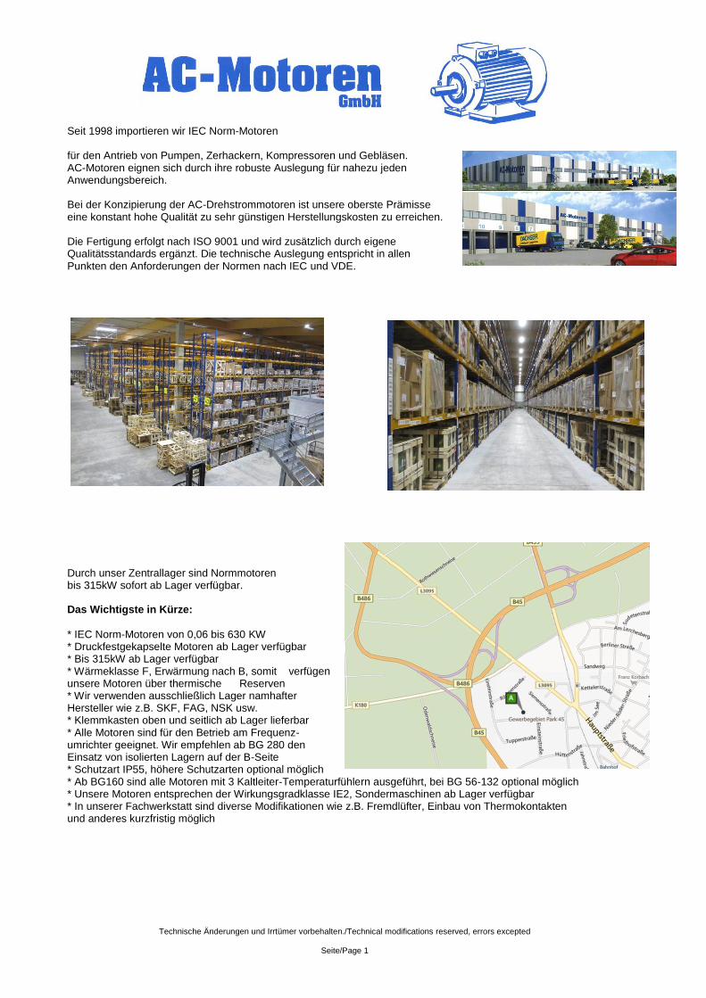
Seit 1998 importieren wir IEC Norm-Motoren für den Antrieb von Pumpen, Zerhackern, Kompressoren und Gebläsen. AC-Motoren eignen sich durch ihre robuste Auslegung für nahezu jeden Anwendungsbereich. Bei der Konzipierung der AC-Drehstrommotoren ist unsere oberste Prämisse eine konstant hohe Qualität zu sehr günstigen Herstellungskosten zu erreichen. Die Fertigung erfolgt nach ISO 9001 und wird zusätzlich durch eigene Qualitätsstandards ergänzt. Die technische Auslegung entspricht in allen Punkten den Anforderungen der Normen nach IEC und VDE.
Durch unser Zentrallager sind Normmotoren bis 315kW sofort ab Lager verfügbar. Das Wichtigste in Kürze:
* IEC Norm-Motoren von 0,06 bis 630 KW * Druckfestgekapselte Motoren ab Lager verfügbar * Bis 315kW ab Lager verfügbar * Wärmeklasse F, Erwärmung nach B, somit verfügen unsere Motoren über thermische Reserven * Wir verwenden ausschließlich Lager namhafter Hersteller wie z.B. SKF, FAG, NSK usw. * Klemmkasten oben und seitlich ab Lager lieferbar * Alle Motoren sind für den Betrieb am Frequenz- umrichter geeignet. Wir empfehlen ab BG 280 den Einsatz von isolierten Lagern auf der B-Seite * Schutzart IP55, höhere Schutzarten optional möglich * Ab BG160 sind alle Motoren mit 3 Kaltleiter-Temperaturfühlern ausgeführt, bei BG 56-132 optional möglich * Unsere Motoren entsprechen der Wirkungsgradklasse IE2, Sondermaschinen ab Lager verfügbar * In unserer Fachwerkstatt sind diverse Modifikationen wie z.B. Fremdlüfter, Einbau von Thermokontakten und anderes kurzfristig möglich
Technische Änderungen und Irrtümer vorbehalten./Technical modifications reserved, errors excepted
Seite/Page 2
Inhaltsverzeichnis / Content
Inhalt Inhaltsverzeichnis / Content ......................................................................................................................................................... 2
Technische Erläuterung ............................................................................................................................................................... 3
Technical instruction .................................................................................................................................................................... 3
Typ ACA Aluminiumgehäuse / Type ACA aluminium-housing ..................................................................................................... 8
Typ ACM Graugussgehäuse / Type ACM cast-iron-housing ........................................................................................................ 9
Aluminium Typenreihe „kleine Motoren“ / Aluminium Housing Types „small motors“ .................................................................. 10
Graugussmotoren “große Motoren” / Cast Iron Housing “big motors”......................................................................................... 11
Aluminium Typenreihe / Aluminium Housing Types ................................................................................................................... 12
Aluminiummotoren mit erhöhter Leistung im kleinerem Gehäuse / ............................................................................................ 13
Aluminium Housing with higher power and smaller frame .......................................................................................................... 13
Graugussmotoren mit erhöhter Leistung im kleinerem Gehäuse / .............................................................................................. 13
Cast Iron Housing with higher power and smaller frame ............................................................................................................ 13
Polumschaltbare Motoren für quadratisch steigendes Gegenmoment / ..................................................................................... 14
speed switchable motors for sqare-grow load torque ................................................................................................................. 14
Aluminium-Motoren Bauform B3 ................................................................................................................................................ 15
Aluminium-Motoren Bauform B3/B5 .......................................................................................................................................... 16
Aluminium-Motoren Bauform B5 ................................................................................................................................................ 17
Aluminium-Motoren Bauform B14 .............................................................................................................................................. 18
Graugussmotoren Bauform B3 .................................................................................................................................................. 19
Graugussmotoren Bauform B3/B5 ............................................................................................................................................. 20
Graugussmotoren Bauform B5 .................................................................................................................................................. 21
Graugussmotoren Bauform B3 (ab BG400) ............................................................................................................................... 22
Graugussmotoren Bauform V1 und B3/B5 (ab BG400) .............................................................................................................. 23
Betriebs- und Wartungsanleitung ............................................................................................................................................... 24
Operating- and maintenance instructions .................................................................................................................................. 24
Schaltbilder / wiring diagram ...................................................................................................................................................... 26
Schaltbilder für polumschaltbare Motoren / ................................................................................................................................ 26
Wiring diagram for speed switchable motors ............................................................................................................................. 26
Nachschmierintervalle / lubrication intervals .............................................................................................................................. 27
Sicherheits- und Inbetriebnahmehinweise für Niederspannungs-Asynchronmotoren ................................................................. 28
Technische Änderungen und Irrtümer vorbehalten./Technical modifications reserved, errors excepted
Seite/Page 3
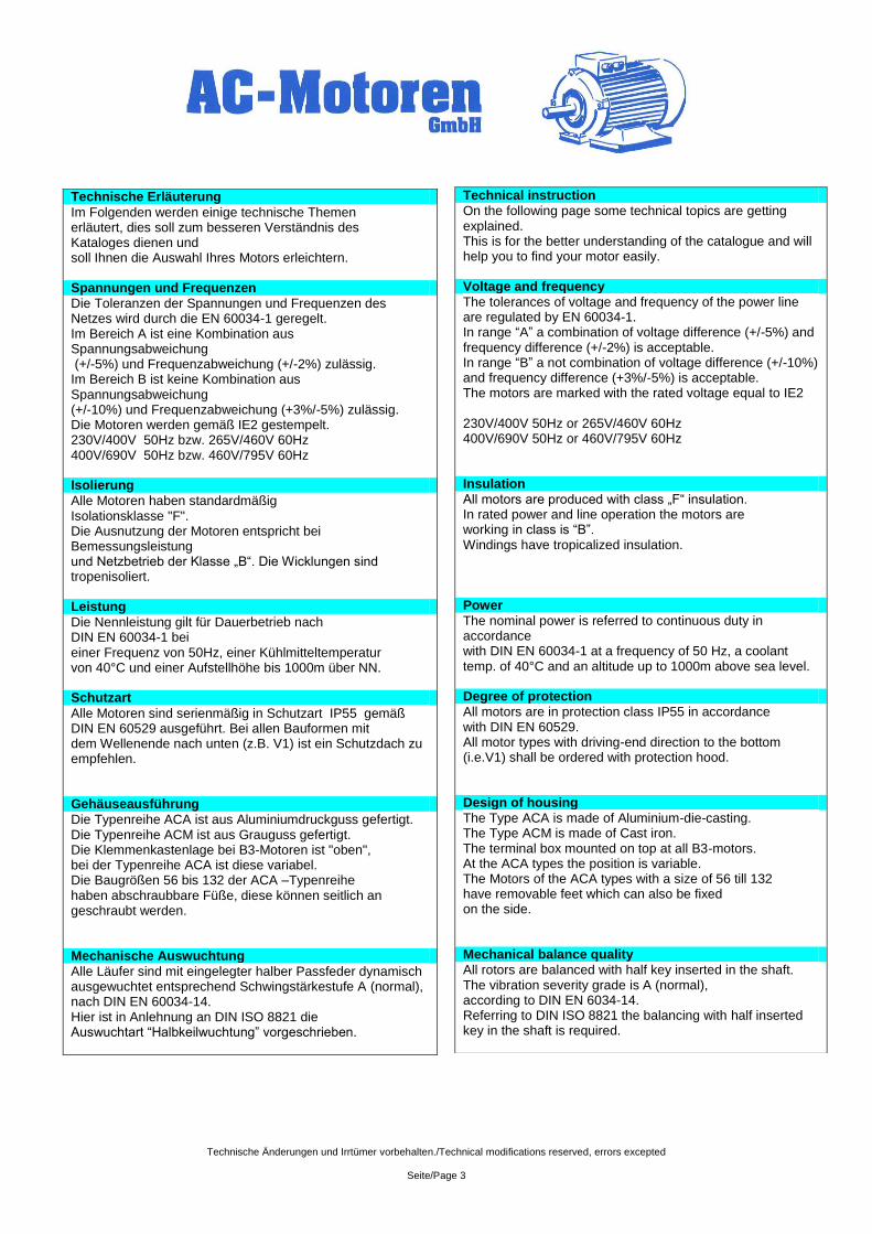
Technical instruction
On the following page some technical topics are getting explained. This is for the better understanding of the catalogue and will help you to find your motor easily. Voltage and frequency
The tolerances of voltage and frequency of the power line are regulated by EN 60034-1. In range “A” a combination of voltage difference (+/-5%) and frequency difference (+/-2%) is acceptable. In range “B” a not combination of voltage difference (+/-10%) and frequency difference (+3%/-5%) is acceptable. The motors are marked with the rated voltage equal to IE2 230V/400V 50Hz or 265V/460V 60Hz 400V/690V 50Hz or 460V/795V 60Hz Insulation
All motors are produced with class „F“ insulation. In rated power and line operation the motors are working in class is “B”. Windings have tropicalized insulation. Power
The nominal power is referred to continuous duty in accordance with DIN EN 60034-1 at a frequency of 50 Hz, a coolant temp. of 40°C and an altitude up to 1000m above sea level. Degree of protection
All motors are in protection class IP55 in accordance with DIN EN 60529. All motor types with driving-end direction to the bottom (i.e.V1) shall be ordered with protection hood. Design of housing
The Type ACA is made of Aluminium-die-casting. The Type ACM is made of Cast iron. The terminal box mounted on top at all B3-motors. At the ACA types the position is variable. The Motors of the ACA types with a size of 56 till 132 have removable feet which can also be fixed on the side. Mechanical balance quality
All rotors are balanced with half key inserted in the shaft. The vibration severity grade is A (normal), according to DIN EN 6034-14. Referring to DIN ISO 8821 the balancing with half inserted key in the shaft is required.
Technische Erläuterung
Im Folgenden werden einige technische Themen erläutert, dies soll zum besseren Verständnis des Kataloges dienen und soll Ihnen die Auswahl Ihres Motors erleichtern. Spannungen und Frequenzen
Die Toleranzen der Spannungen und Frequenzen des Netzes wird durch die EN 60034-1 geregelt. Im Bereich A ist eine Kombination aus Spannungsabweichung (+/-5%) und Frequenzabweichung (+/-2%) zulässig. Im Bereich B ist keine Kombination aus Spannungsabweichung (+/-10%) und Frequenzabweichung (+3%/-5%) zulässig. Die Motoren werden gemäß IE2 gestempelt. 230V/400V 50Hz bzw. 265V/460V 60Hz 400V/690V 50Hz bzw. 460V/795V 60Hz Isolierung
Alle Motoren haben standardmäßig Isolationsklasse "F". Die Ausnutzung der Motoren entspricht bei Bemessungsleistung und Netzbetrieb der Klasse „B“. Die Wicklungen sind tropenisoliert. Leistung
Die Nennleistung gilt für Dauerbetrieb nach DIN EN 60034-1 bei einer Frequenz von 50Hz, einer Kühlmitteltemperatur von 40°C und einer Aufstellhöhe bis 1000m über NN. Schutzart
Alle Motoren sind serienmäßig in Schutzart IP55 gemäß DIN EN 60529 ausgeführt. Bei allen Bauformen mit dem Wellenende nach unten (z.B. V1) ist ein Schutzdach zu empfehlen. Gehäuseausführung
Die Typenreihe ACA ist aus Aluminiumdruckguss gefertigt. Die Typenreihe ACM ist aus Grauguss gefertigt. Die Klemmenkastenlage bei B3-Motoren ist "oben", bei der Typenreihe ACA ist diese variabel. Die Baugrößen 56 bis 132 der ACA –Typenreihe haben abschraubbare Füße, diese können seitlich an geschraubt werden. Mechanische Auswuchtung
Alle Läufer sind mit eingelegter halber Passfeder dynamisch ausgewuchtet entsprechend Schwingstärkestufe A (normal), nach DIN EN 60034-14. Hier ist in Anlehnung an DIN ISO 8821 die Auswuchtart “Halbkeilwuchtung” vorgeschrieben.
Technische Änderungen und Irrtümer vorbehalten./Technical modifications reserved, errors excepted
Seite/Page 4
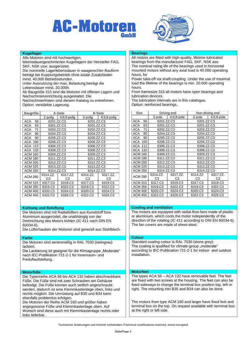
Kugellager
Alle Motoren sind mit hochwertigen, lebensdauergeschmierten Kugellagern der Hersteller FAG, SKF, NSK usw. ausgerüstet. Die nominelle Lagerlebensdauer in waagerechter Bauform beträgt bei Kupplungsbetrieb ohne axiale Zusatzlasten mind. 40.000 Betriebsstunden. Unter Ausnutzung der max. Belastung beträgt die Lebensdauer mind. 20.000h. Ab Baugröße 315 sind die Motoren mit offenen Lagern und Nachschmiereinrichtung ausgestattet. Die Nachschmierfristen sind diesem Katalog zu entnehmen. Option: verstärkte Lagerung. Baugröße A-Seite B-Seite
2-polig 4;6;8-polig 2-polig 4;6;8-polig
ACA 56 6201.ZZ.C3 6201.ZZ.C3
ACA 63 6201.ZZ.C3 6201.ZZ.C3
ACA 71 6202.ZZ.C3 6202.ZZ.C3
ACA 80 6204.ZZ.C3 6204.ZZ.C3
ACA 90 6205.ZZ.C3 6205.ZZ.C3
ACA 100 6206.ZZ.C3 6206.ZZ.C3
ACA 112 6306.ZZ.C3 6306.ZZ.C3
ACA 132 6308.ZZ.C3 6308.ZZ.C3
ACM 160 6309.ZZ.C3 6309.ZZ.C3
ACM 180 6311.ZZ.C3 6311.ZZ.C3
ACM 200 6312.ZZ.C3 6312.ZZ.C3
ACM 225 6313.ZZ.C3 6313.ZZ.C3
ACM 250 6314.ZZ.C3 6314.ZZ.C3
ACM 280 6314.ZZ.
C3 6317.ZZ.
C3 6314.ZZ.
C3 6317.ZZ.
C3
ACM 315 6317.C3 6319.C3 6317.C3 6319.C3
ACM 355 6319.C3 6322.C3 6319.C3 6322.C3
ACM 400 6320.C3 6324.C3 6320.C3 6324.C3
ACM 450 6322.C3 6326.C3 6322.C3 6326.C3
Kühlung und Belüftung
Die Motoren sind mit Radiallüftern aus Kunststoff bzw. Aluminium ausgerüstet, die unabhängig von der Drehrichtung des Motors kühlen (IC 411 nach DIN EN 60034-6). Die Lüfterhauben der Motoren sind generell aus Stahlblech. Farbe
Die Motoren sind serienmäßig in RAL 7030 (steingrau) lackiert. Die Lackierung ist geeignet für die Klimagruppe „Moderate“ nach IEC-Publikation 721-2-1 für Innenraum- und Freiluftaufstellung. Motorfüße
Die Typenreihe ACA 56 bis ACA 132 haben abschraubbare Füße. Die Füße sind mit zwei Schrauben am Gehäuse befestigt. Die Füße können auch seitlich angeschraubt werden, dadurch ist eine Klemmkastenlage oben, links und rechts möglich. Die Umrüstung auf B35 und B34 kann ebenfalls problemlos erfolgen. Die Motoren der Reihe ACM 160 und größer haben angegossene Füße und Klemmkastenlage oben. Auf Wunsch sind diese auch mit Klemmkastenlage rechts oder links lieferbar.
Bearings
All motors are fitted with high-quality, lifetime-lubricated bearings from the manufacturer FAG, SKF, NSK aso. The nominal rating life of the bearings used in horizontal mounted motors without any axial load is 40.000 operating hours, for Power take-off via shaft-coupling. Under the use of maximal load the lifetime of the bearings is min. 20.000 operating hours. From framesize 315 all motors have open bearings and lubrication devices. The lubrication intervals are in this catalogue. Option: reinforced bearings.
Size Driving end Non-driving end
2-pole 4;6;8-pole 2-pole 4;6;8-pole
ACA 56 6201.ZZ.C3 6201.ZZ.C3
ACA 63 6201.ZZ.C3 6201.ZZ.C3
ACA 71 6202.ZZ.C3 6202.ZZ.C3
ACA 80 6204.ZZ.C3 6204.ZZ.C3
ACA 90 6205.ZZ.C3 6205.ZZ.C3
ACA 100 6206.ZZ.C3 6206.ZZ.C3
ACA 112 6306.ZZ.C3 6306.ZZ.C3
ACA 132 6308.ZZ.C3 6308.ZZ.C3
ACM 160 6309.ZZ.C3 6309.ZZ.C3
ACM 180 6311.ZZ.C3 6311.ZZ.C3
ACM 200 6312.ZZ.C3 6312.ZZ.C3
ACM 225 6313.ZZ.C3 6313.ZZ.C3
ACM 250 6314.ZZ.C3 6314.ZZ.C3
ACM 280 6314.ZZ.
C3 6317.ZZ.
C3 6314.ZZ.
C3 6317.ZZ.
C3
ACM 315 6317.C3 6319.C3 6317.C3 6319.C3
ACM 355 6319.C3 6322.C3 6319.C3 6322.C3
ACM 400 6320.C3 6324.C3 6320.C3 6324.C3
ACM 450 6322.C3 6326.C3 6322.C3 6326.C3
Cooling and ventilation
The motors are equipped with radial-flow-fans made of plastic or aluminium, which cools the motor independently of the direction of the rotating (IC 411 according to DIN EN 60034-6). The fan covers are made of sheet-steel. Colour
Standard coating colour is RAL 7030 (stone grey). The coating is qualified for climate-group „moderate“ according to IEC-Publication 721-2-1 for indoor- and outdoor installation. Motorfeet
The types ACA 56 – ACA 132 have removable feet. The feet are fixed with two screws at the housing. The feet can also be fixed sideways to change the terminal box position top, left or right. The mounting into B35 and B34 can also be done. The motors from type ACM 160 and larger have fixed feet and terminal box on the top. On request available with terminal box at the right or left side.
Technische Änderungen und Irrtümer vorbehalten./Technical modifications reserved, errors excepted
Seite/Page 5
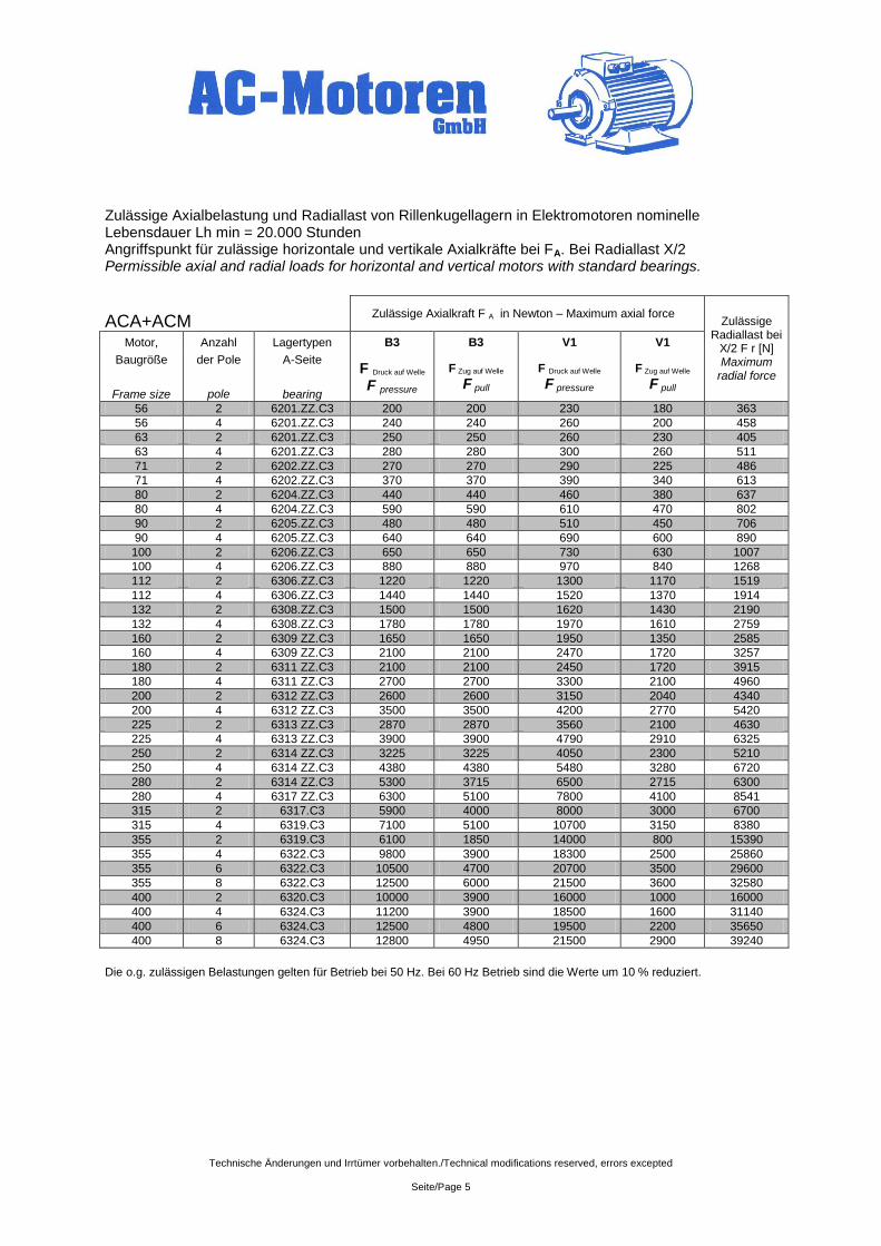
Zulässige Axialbelastung und Radiallast von Rillenkugellagern in Elektromotoren nominelle Lebensdauer Lh min = 20.000 Stunden Angriffspunkt für zulässige horizontale und vertikale Axialkräfte bei FA. Bei Radiallast X/2 Permissible axial and radial loads for horizontal and vertical motors with standard bearings.
ACA+ACM Zulässige Axialkraft F A in Newton – Maximum axial force
Zulässige Radiallast bei
X/2 F r [N] Maximum
radial force
Motor, Anzahl Lagertypen B3 B3 V1 V1
Baugröße
Frame size
der Pole
pole
A-Seite
bearing
F Druck auf Welle
F pressure
F Zug auf Welle
F pull F Druck auf Welle
F pressure F Zug auf Welle
F pull
56 2 6201.ZZ.C3 200 200 230 180 363
56 4 6201.ZZ.C3 240 240 260 200 458
63 2 6201.ZZ.C3 250 250 260 230 405
63 4 6201.ZZ.C3 280 280 300 260 511
71 2 6202.ZZ.C3 270 270 290 225 486
71 4 6202.ZZ.C3 370 370 390 340 613
80 2 6204.ZZ.C3 440 440 460 380 637
80 4 6204.ZZ.C3 590 590 610 470 802
90 2 6205.ZZ.C3 480 480 510 450 706
90 4 6205.ZZ.C3 640 640 690 600 890
100 2 6206.ZZ.C3 650 650 730 630 1007
100 4 6206.ZZ.C3 880 880 970 840 1268
112 2 6306.ZZ.C3 1220 1220 1300 1170 1519
112 4 6306.ZZ.C3 1440 1440 1520 1370 1914
132 2 6308.ZZ.C3 1500 1500 1620 1430 2190
132 4 6308.ZZ.C3 1780 1780 1970 1610 2759
160 2 6309 ZZ.C3 1650 1650 1950 1350 2585
160 4 6309 ZZ.C3 2100 2100 2470 1720 3257
180 2 6311 ZZ.C3 2100 2100 2450 1720 3915
180 4 6311 ZZ.C3 2700 2700 3300 2100 4960
200 2 6312 ZZ.C3 2600 2600 3150 2040 4340
200 4 6312 ZZ.C3 3500 3500 4200 2770 5420
225 2 6313 ZZ.C3 2870 2870 3560 2100 4630
225 4 6313 ZZ.C3 3900 3900 4790 2910 6325
250 2 6314 ZZ.C3 3225 3225 4050 2300 5210
250 4 6314 ZZ.C3 4380 4380 5480 3280 6720
280 2 6314 ZZ.C3 5300 3715 6500 2715 6300
280 4 6317 ZZ.C3 6300 5100 7800 4100 8541
315 2 6317.C3 5900 4000 8000 3000 6700
315 4 6319.C3 7100 5100 10700 3150 8380
355 2 6319.C3 6100 1850 14000 800 15390
355 4 6322.C3 9800 3900 18300 2500 25860
355 6 6322.C3 10500 4700 20700 3500 29600
355 8 6322.C3 12500 6000 21500 3600 32580
400 2 6320.C3 10000 3900 16000 1000 16000
400 4 6324.C3 11200 3900 18500 1600 31140
400 6 6324.C3 12500 4800 19500 2200 35650
400 8 6324.C3 12800 4950 21500 2900 39240
Die o.g. zulässigen Belastungen gelten für Betrieb bei 50 Hz. Bei 60 Hz Betrieb sind die Werte um 10 % reduziert.
Technische Änderungen und Irrtümer vorbehalten./Technical modifications reserved, errors excepted
Seite/Page 6
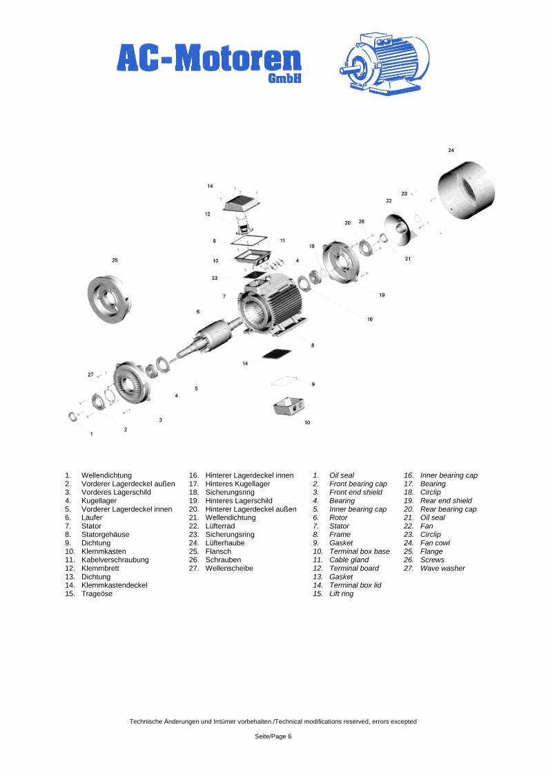
1. Wellendichtung 16. Hinterer Lagerdeckel innen 1. Oil seal 16. Inner bearing cap 2. Vorderer Lagerdeckel außen 17. Hinteres Kugellager 2. Front bearing cap 17. Bearing 3. Vorderes Lagerschild 18. Sicherungsring 3. Front end shield 18. Circlip 4. Kugellager 19. Hinteres Lagerschild 4. Bearing 19. Rear end shield 5. Vorderer Lagerdeckel innen 20. Hinterer Lagerdeckel außen 5. Inner bearing cap 20. Rear bearing cap 6. Läufer 21. Wellendichtung 6. Rotor 21. Oil seal 7. Stator 22. Lüfterrad 7. Stator 22. Fan 8. Statorgehäuse 23. Sicherungsring 8. Frame 23. Circlip 9. Dichtung 24. Lüfterhaube 9. Gasket 24. Fan cowl 10. Klemmkasten 25. Flansch 10. Terminal box base 25. Flange 11. Kabelverschraubung 26. Schrauben 11. Cable gland 26. Screws 12. Klemmbrett 27. Wellenscheibe 12. Terminal board 27. Wave washer 13. Dichtung 13. Gasket 14. Klemmkastendeckel 14. Terminal box lid 15. Trageöse 15. Lift ring
13
23
Technische Änderungen und Irrtümer vorbehalten./Technical modifications reserved, errors excepted
Seite/Page 7
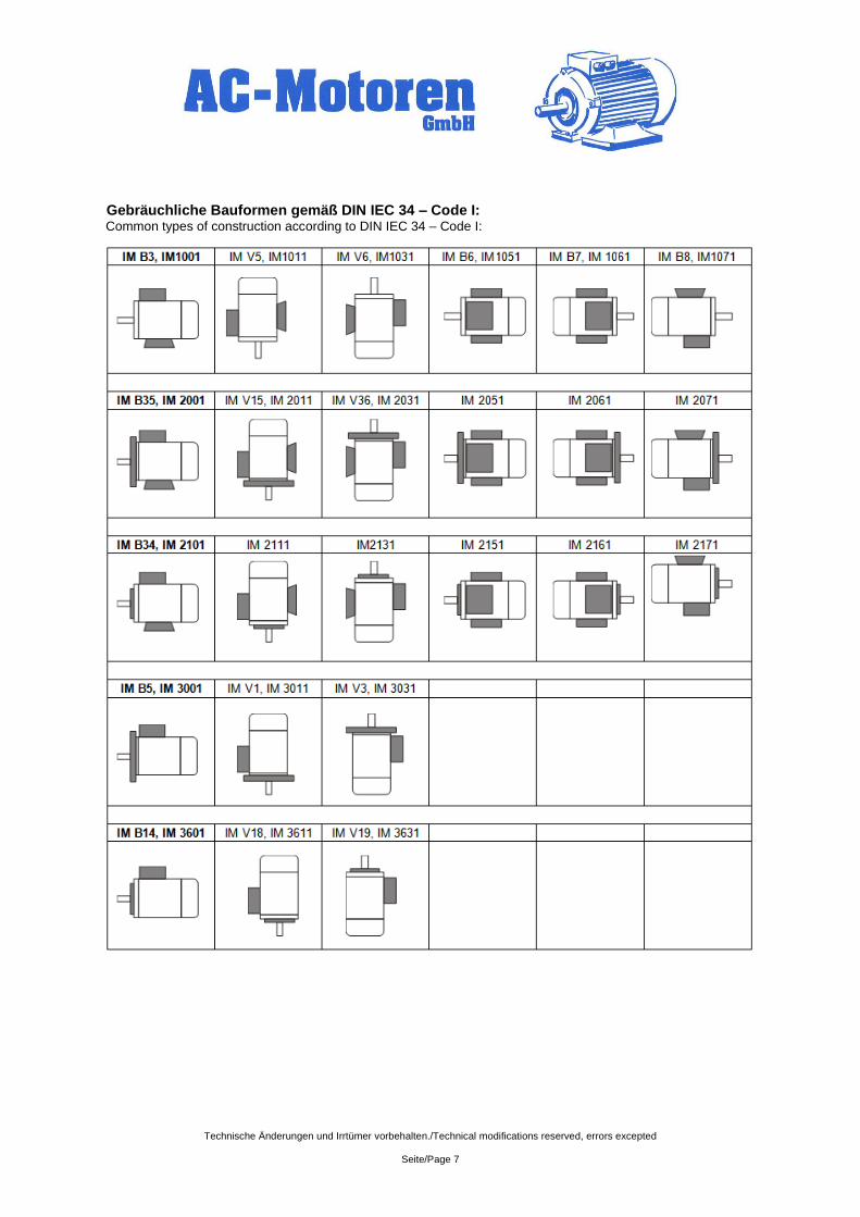
Gebräuchliche Bauformen gemäß DIN IEC 34 – Code I: Common types of construction according to DIN IEC 34 – Code I:
Technische Änderungen und Irrtümer vorbehalten./Technical modifications reserved, errors excepted
Seite/Page 8
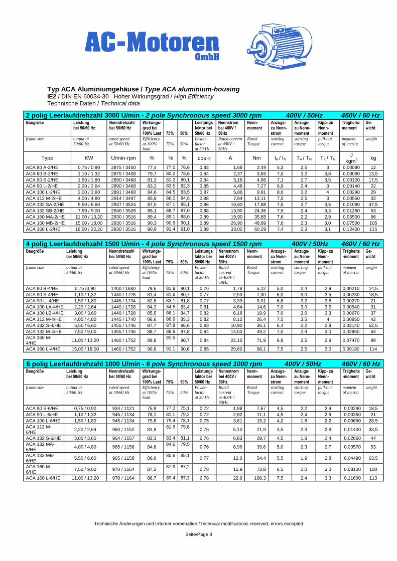
Typ ACA Aluminiumgehäuse / Type ACA aluminium-housing IE2 / DIN EN 60034-30 Hoher Wirkungsgrad / High Efficiency Technische Daten / Technical data
2 polig Leerlaufdrehzahl 3000 U/min - 2 pole Synchronous speed 3000 rpm 400V / 50Hz 460V / 60 Hz Baugröße Leistung
bei 50/60 Hz Nenndrehzahl bei 50/60 Hz
Wirkungs-grad bei 100% Last
75%
50%
Leistungsfaktor bei 50/60 Hz
Nennstrom bei 400V / 50Hz
Nenn-moment
Anzugs-zu Nenn- strom
Anzugs- zu Nenn- moment
Kipp- zu Nenn-moment
Trägheits-moment
Ge-wicht
frame size
output at
50/60 Hz
rated speed
at 50/60 Hz
Efficiency
at 100%
load
75%
50%
Power-
factor
at 50 Hz
Rated current
at 400V /
50Hz
Rated
Torque
starting
current
starting
torque
pull-out
torque
moment
of inertia
weight
Type KW U/min-rpm % % % cos A Nm IA / IN TA / TN TK / TN J
kgm2
kg
ACA 80 A-2/HE 0,75 / 0,90 2875 / 3450 77,4 77,0 76,6 0,83 1,68 2,49 5,3 2,5 3 0,00080 12
ACA 80 B-2/HE 1,10 / 1,32 2875 / 3408 79,7 80,2 78,6 0,84 2,37 3,65 7,0 3,2 3,8 0,00090 13,5
ACA 90 S-2/HE 1,50 / 1,80 2890 / 3468 81,3 81,2 80,1 0,84 3,16 4,96 7,1 2,7 3,5 0,00120 17,5
ACA 90 L-2/HE 2,20 / 2,64 2890 / 3468 83,2 83,5 82,3 0,85 4,48 7,27 6,9 2,4 3 0,00140 22
ACA 100 L-2/HE 3,00 / 3,60 2891 / 3468 84,6 84,5 83,5 0,87 5,86 9,91 8,0 3,2 4 0,00290 29
ACA 112 M-2/HE 4,00 / 4,80 2914 / 3497 85,8 86,0 84,8 0,88 7,64 13,11 7,5 2,5 3 0,00550 32
ACA 132 SA-2/HE 5,50 / 6,60 2937 / 3524 87,0 87,1 85,1 0,86 10,60 17,88 7,5 2,7 3,5 0,01090 47,5
ACA 132 SB-2/HE 7,50 / 9,00 2940 / 3528 88,1 88,7 87,0 0,88 13,90 24,36 7,5 2,4 3,3 0,01260 53
ACA 160 MA-2/HE 11,00 / 13,20 2930 / 3516 89,4 89,1 88,0 0,89 19,90 35,85 7,6 2,2 2,9 0,05500 96
ACA 160 MB-2/HE 15,00 / 18,00 2930 / 3516 90,3 90,9 90,1 0,89 26,90 48,89 7,6 2,3 3,0 0,07500 105
ACA 160 L-2/HE 18,50 / 22,20 2930 / 3516 90,9 91,4 91,0 0,89 33,00 60,29 7,4 2,3 3,1 0,12400 115
4 polig Leerlaufdrehzahl 1500 U/min - 4 pole Synchronous speed 1500 rpm 400V / 50Hz 460V / 60 Hz Baugröße Leistung
bei 50/60 Hz Nenndrehzahl bei 50/60 Hz
Wirkungs-grad bei 100% Last
75%
50%
Leistungsfaktor bei 50/60 Hz
Nennstrom bei 400V / 50Hz
Nenn-moment
Anzugs-zu Nenn- strom
Anzugs- zu Nenn- moment
Kipp- zu Nenn-moment
Trägheits-moment
Ge-wicht
frame size
output at
50/60 Hz
rated speed
at 50/60 Hz
Efficiency
at 100%
load
75%
50%
Power-
factor
at 50 Hz
Rated
current
at 400V /
50Hz
Rated
Torque
starting
current
starting
torque
pull-out
torque
moment
of inertia
weight
ACA 80 B-4/HE 0,75 /0,90 1400 / 1680 79,6 81,8 80,1 0,76 1,78 5,12 5,0 2,4 2,9 0,00210 14,5
ACA 90 S-4/HE 1,10 / 1,32 1440 / 1728 81,4 81,6 80,7 0,77 2,53 7,30 6,0 3,0 3,5 0,00230 18,5
ACA 90 L -4/HE 1,50 / 1,80 1445 / 1734 82,8 83,1 81,8 0,77 3,39 9,91 6,8 3,2 3,8 0,00270 21
ACA 100 LA-4/HE 2,20 / 2,64 1440 / 1728 84,3 84,5 83,4 0,81 4,64 14,6 7,0 3,0 3,5 0,00540 31
ACA 100 LB-4/HE 3,00 / 3,60 1440 / 1728 85,5 86,1 84,7 0,82 6,18 19,9 7,0 2,6 3,3 0,00670 37
ACA 112 M-4/HE 4,00 / 4,80 1445 / 1740 86,6 86,9 85,3 0,82 8,12 26,4 7,5 3,5 4 0,00950 42
ACA 132 S-4/HE 5,50 / 6,60 1455 / 1746 87,7 87,8 86,6 0,83 10,90 36,1 6,4 2,2 2,8 0,02140 52,5
ACA 132 M-4/HE 7,50 / 9,00 1455 / 1746 88,7 88,9 87,8 0,84 14,50 49,2 7,0 2,4 3,0 0,02960 64
ACA 160 M-4/HE
11,00 / 13,20 1460 / 1752 89,8 91,5
90,7 0,84 22,10 71,9 6,9 2,5 2,9 0,07470 99
ACA 160 L-4/HE 15,00 / 18,00 1460 / 1752 90,6 91,1 90,6 0,85 29,60 98,1 7,5 2,5 3,0 0,09180 114
6 polig Leerlaufdrehzahl 1000 U/min - 6 pole Synchronous speed 1000 rpm 400V / 50Hz 460V / 60 Hz Baugröße Leistung
bei 50/60 Hz Nenndrehzahl bei 50/60 Hz
Wirkungs-grad bei 100% Last
75%
50%
Leistungsfaktor bei 50/60 Hz
Nennstrom bei 400V / 50Hz
Nenn-moment
Anzugs-zu Nenn- strom
Anzugs- zu Nenn- moment
Kipp- zu Nenn-moment
Trägheits-moment
Ge-wicht
frame size
output at
50/60 Hz
rated speed
at 50/60 Hz
Efficiency
at 100%
load
75%
50%
Power-
factor
at 50 Hz
Rated
current
at 400V /
50Hz
Rated
Torque
starting
current
starting
torque
pull-out
torque
moment
of inertia
weight
ACA 90 S-6/HE 0,75 / 0,90 934 / 1121 75,9 77,2 75,1 0,72 1,98 7,67 4,5 2,2 2,4 0,00290 18,5
ACA 90 L-6/HE 1,10 / 1,32 945 / 1134 78,1 81,1 79,2 0,72 2,82 11,1 4,5 2,4 2,6 0,00350 21
ACA 100 L-6/HE 1,50 / 1,80 945 / 1134 79,8 79,4 78,1 0,75 3,61 15,2 4,2 1,8 2,2 0,00690 28,5
ACA 112 M-6/HE
2,20 / 2,64 960 / 1152 81,8 81,9 79,8
0,76 5,10 21,9 4,5 2,3 2,8 0,01400 33,5
ACA 132 S-6/HE 3,00 / 3,60 964 / 1157 83,3 83,4 81,1 0,76 6,83 29,7 4,5 1,8 2,4 0,02860 44
ACA 132 MA-6/HE
4,00 / 4,80 965 / 1158 84,6 84,6 79,5
0,76 8,96 39,6 5,0 2,3 2,7 0,03570 53
ACA 132 MB-6/HE
5,50 / 6,60 965 / 1158 86,0 85,8 85,1
0,77 12,0 54,4 5,5 1,9 2,8 0,04490 63,5
ACA 160 M-6/HE
7,50 / 9,00 970 / 1164 87,2 87,9 87,2
0,78 15,9 73,8 6,5 2,0 3,0 0,08100 100
ACA 160 L-6/HE 11,00 / 13,20 970 / 1164 88,7 89,4 87,3 0,78 22,9 108,3 7,5 2,4 3,3 0,11600 113
Technische Änderungen und Irrtümer vorbehalten./Technical modifications reserved, errors excepted
Seite/Page 9
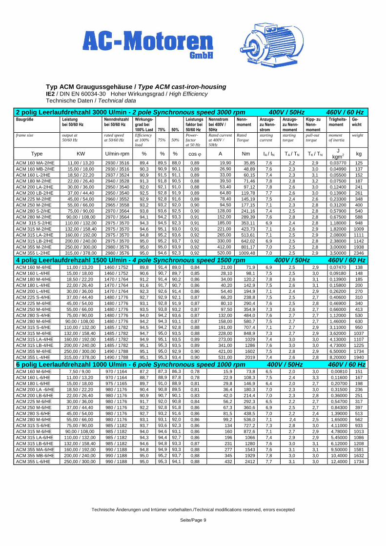
Typ ACM Graugussgehäuse / Type ACM cast-iron-housing IE2 / DIN EN 60034-30 Hoher Wirkungsgrad / High Efficiency Technische Daten / Technical data
2 polig Leerlaufdrehzahl 3000 U/min - 2 pole Synchronous speed 3000 rpm 400V / 50Hz 460V / 60 Hz Baugröße Leistung
bei 50/60 Hz Nenndrehzahl bei 50/60 Hz
Wirkungs-grad bei 100% Last
75%
50%
Leistungsfaktor bei 50/60 Hz
Nennstrom bei 400V / 50Hz
Nenn-moment
Anzugs-zu Nenn- strom
Anzugs- zu Nenn- moment
Kipp- zu Nenn-moment
Trägheits-moment
Ge-wicht
frame size
output at
50/60 Hz
rated speed
at 50/60 Hz
Efficiency
at 100%
load
75%
50%
Power-
factor
at 50 Hz
Rated current
at 400V /
50Hz
Rated
Torque
starting
current
starting
torque
pull-out
torque
moment
of inertia
weight
Type KW U/min-rpm % % % cos A Nm IA / IN TA / TN TK / TN J
kgm2
kg
ACM 160 MA-2/HE 11,00 / 13,20 2930 / 3516 89,4 89,5 88,0 0,89 19,90 35,85 7,6 2,2 2,9 0,03770 125
ACM 160 MB-2/HE 15,00 / 18,00 2930 / 3516 90,3 90,9 90,1 0,89 26,90 48,89 7,6 2,3 3,0 0,04990 137
ACM 160 L-2/HE 18,50 / 22,20 2937 / 3524 90,9 91,5 91,1 0,89 33,00 60,15 7,4 2,3 3,1 0,05500 152
ACM 180 M-2/HE 22,00 / 26,40 2940 / 3528 91,3 91,8 90,5 0,88 39,50 71,46 7,8 2,8 3,2 0,07500 187
ACM 200 LA-2/HE 30,00 / 36,00 2950 / 3540 92,0 92,1 91,0 0,88 53,40 97,12 7,8 2,6 3,0 0,12400 241
ACM 200 LB-2/HE 37,00 / 44,40 2950 / 3540 92,5 92,8 91,9 0,89 64,80 119,78 7,7 2,6 3,0 0,13900 261
ACM 225 M-2/HE 45,00 / 54,00 2960 / 3552 92,9 92,8 91,6 0,89 78,40 145,19 7,5 2,4 2,6 0,23300 348
ACM 250 M-2/HE 55,00 / 66,00 2965 / 3558 93,2 93,2 92,0 0,90 94,50 177,15 7,1 2,3 2,8 0,31200 400
ACM 280 S-2/HE 75,00 / 90,00 2970 / 3564 93,8 93,6 92,5 0,90 128,00 241,16 7,4 2,5 2,8 0,57900 540
ACM 280 M-2/HE 90,00 / 108,00 2970 / 3564 94,1 94,2 93,3 0,91 152,00 289,39 7,6 2,8 2,8 0,67500 588
ACM 315 S-2/HE 110,00 / 132,00 2975 / 3570 94,3 94,5 92,3 0,91 185,00 353,11 6,9 2,4 2,8 1,18000 948
ACM 315 M-2/HE 132,00 / 158,40 2975 / 3570 94,6 95,1 93,0 0,91 221,00 423,73 7,1 2,6 2,9 1,82000 1009
ACM 315 LA-2/HE 160,00 / 192,00 2975 / 3570 94,8 95,2 93,6 0,92 265,00 513,61 7,1 2,5 2,9 2,08000 1111
ACM 315 LB-2/HE 200,00 / 240,00 2975 / 3570 95,0 95,2 93,7 0,92 330,00 642,02 6,9 2,5 2,8 2,38000 1142
ACM 355 M-2/HE 250,00 / 300,00 2980 / 3576 95,0 95,0 93,9 0,92 412,00 801,17 7,0 2,5 2,8 3,00000 1938
ACM 355 L-2/HE 315,00 / 378,00 2980 / 3576 95,0 94,6 92,3 0,92 520,00 1009,48 7,0 2,5 2,9 3,50000 2346
4 polig Leerlaufdrehzahl 1500 U/min - 4 pole Synchronous speed 1500 rpm 400V / 50Hz 460V / 60 Hz ACM 160 M-4/HE 11,00 / 13,20 1460 / 1752 89,8 91,4 89,0 0,84 21,00 71,9 6,9 2,5 2,9 0,07470 138
ACM 160 L-4/HE 15,00 / 18,00 1460 / 1752 90,6 90,7 89,7 0,85 28,10 98,1 7,5 2,5 3,0 0,09180 148
ACM 180 M-4/HE 18,50 / 22,20 1470 / 1764 91,2 91,4 90,2 0,86 34,00 120,2 7,8 2,6 3,1 0,13900 185
ACM 180 L-4/HE 22,00 / 26,40 1470 / 1764 91,6 91,7 90,7 0,86 40,20 142,9 7,5 2,6 3,1 0,15800 200
ACM 200 L-4/HE 30,00 / 36,00 1470 / 1764 92,3 92,6 91,4 0,86 54,40 194,9 7,1 2,4 2,9 0,26200 270
ACM 225 S-4/HE 37,00 / 44,40 1480 / 1776 92,7 92,9 92,1 0,87 66,20 238,8 7,5 2,5 2,7 0,40600 310
ACM 225 M-4/HE 45,00 / 54,00 1480 / 1776 93,1 92,8 91,9 0,87 80,10 290,4 7,6 2,5 2,8 0,46900 340
ACM 250 M-4/HE 55,00 / 66,00 1480 / 1776 93,5 93,8 93,2 0,87 97,50 354,9 7,3 2,6 2,7 0,66000 413
ACM 280 S-4/HE 75,00 / 90,00 1480 / 1776 94,0 94,2 93,6 0,87 132,00 484,0 7,6 2,7 2,7 1,12000 530
ACM 280 M-4/HE 90,00 / 108,00 1480 / 1776 94,2 94,3 93,1 0,87 158,00 580,7 7,5 2,7 2,7 1,46000 630
ACM 315 S-4/HE 110,00 / 132,00 1485 / 1782 94,5 94,2 92,8 0,88 191,00 707,4 7,1 2,7 2,9 3,11000 950
ACM 315 M-4/HE 132,00 / 158,40 1485 / 1782 94,7 95,0 93,5 0,88 228,00 848,9 7,3 2,7 2,9 3,62000 1037
ACM 315 LA-4/HE 160,00 / 192,00 1485 / 1782 94,9 95,1 93,5 0,89 273,00 1029 7,4 3,0 3,0 4,13000 1107
ACM 315 LB-4/HE 200,00 / 240,00 1485 / 1782 95,1 95,3 93,5 0,89 341,00 1286 7,6 3,0 3,0 4,73000 1225
ACM 355 M-4/HE 250,00 / 300,00 1490 / 1788 95,1 95,0 92,9 0,90 421,00 1602 7,5 2,8 2,9 6,50000 1734
ACM 355 L-4/HE 315,00 / 378,00 1490 / 1788 95,1 95,3 93,4 0,90 531,00 2019 7,4 2,6 2,8 8,20000 1940
6 polig Leerlaufdrehzahl 1000 U/min - 6 pole Synchronous speed 1000 rpm 400V / 50Hz 460V / 60 Hz ACM 160 M-6/HE 7,50 / 9,00 970 / 1164 87,2 87,3 86,3 0,78 15,9 73,8 6,5 2,0 3,0 0,00810 151
ACM 160 L-6/HE 11,00 / 13,20 970 / 1164 88,7 88,9 87,8 0,78 22,9 108,3 7,5 2,4 3,3 0,11600 167
ACM 180 L-6/HE 15,00 / 18,00 975 / 1165 89,7 91,0 88,9 0,81 29,8 146,9 6,4 2,0 2,7 0,20700 198
ACM 200 LA -6/HE 18,50 / 22,20 980 / 1176 90,4 90,8 89,5 0,81 36,4 180,3 7,0 2,3 3,0 0,31500 236
ACM 200 LB-6/HE 22,00 / 26,40 980 / 1176 90,9 90,7 90,1 0,83 42,0 214,4 7,0 2,3 2,8 0,36000 251
ACM 225 M-6/HE 30,00 / 36,00 980 / 1176 91,7 92,0 90,8 0,84 56,2 292,3 6,5 2,2 2,7 0,54700 317
ACM 250 M-6/HE 37,00 / 44,40 980 / 1176 92,2 92,8 91,8 0,86 67,3 360,6 6,9 2,5 2,7 0,84300 397
ACM 280 S-6/HE 45,00 / 54,00 980 / 1176 92,7 93,2 91,6 0,86 81,5 438,5 7,0 2,2 2,4 1,39000 513
ACM 280 M-6/HE 55,00 / 66,00 980 / 1176 93,1 93,1 92,0 0,86 99,2 536,0 7,1 2,4 2,5 1,65000 562
ACM 315 S-6/HE 75,00 / 90,00 985 / 1182 93,7 93,6 92,3 0,86 134 727,2 7,3 2,8 3,0 4,11000 933
ACM 315 M-6/HE 90,00 / 108,00 985 / 1182 94,0 94,6 93,1 0,86 160 872,6 7,1 2,7 2,9 4,78000 1013
ACM 315 LA-6/HE 110,00 / 132,00 985 / 1182 94,3 94,4 92,7 0,86 196 1066 7,4 2,9 2,9 5,45000 1086
ACM 315 LB-6/HE 132,00 / 158,40 985 / 1182 94,6 94,8 93,3 0,87 231 1280 7,6 3,0 3,1 6,12000 1208
ACM 355 MA-6/HE 160,00 / 192,00 990 / 1188 94,8 94,9 93,3 0,88 277 1543 7,6 3,1 3,1 9,50000 1581
ACM 355 MB-6/HE 200,00 / 240,00 990 / 1188 95,0 95,2 93,7 0,88 345 1929 7,8 3,0 3,0 10,4000 1632
ACM 355 L-6/HE 250,00 / 300,00 990 / 1188 95,0 95,3 94,1 0,88 432 2412 7,7 3,1 3,0 12,4000 1734
Technische Änderungen und Irrtümer vorbehalten./Technical modifications reserved, errors excepted
Seite/Page 10
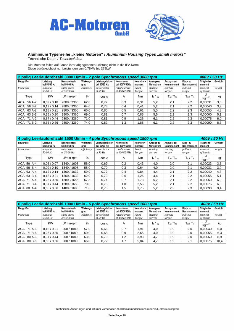
Aluminium Typenreihe „kleine Motoren“ / Aluminium Housing Types „small motors“ Technische Daten / Technical data
Die Motoren fallen auf Grund ihrer abgegebenen Leistung nicht in die IE2-Norm. Diese berücksichtigt nur Leistungen von 0,75kW bis 375kW
2 polig Leerlaufdrehzahl 3000 U/min - 2 pole Synchronous speed 3000 rpm 400V / 50 Hz Baugröße Leistung
bei 50/60 Hz Nenndrehzahl bei 50/60 Hz
Wirkungs-grad
Leistungsfaktor bei 50/60 Hz
Nennstrom bei 400V/50Hz
Nenndreh-moment
Anzugs-zu Nennstrom
Anzugs- zu Nennmoment
Kipp- zu Nennmoment
Trägheits-moment
Gewicht
frame size
output at
50/60 Hz
rated speed
at 50/60 Hz
efficiency powerfactor
at 50 Hz
rated current
at 400V/50Hz
Rated
Torque
starting
current
starting
torque
pull-out
torque
moment
of inertia
weight
Type KW U/min-rpm % cos A Nm IA / IN TA / TN TK / TN J
kgm2
kg
ACA 56 A-2 0,09 / 0,10 2800 / 3360 62,0 0,77 0,3 0,31 5,2 2,1 2,2 0,00031 3,6
ACA 56 B-2 0,12 / 0,14 2800 / 3360 64,0 0,78 0,4 0,41 5,2 2,1 2,2 0,00040 3,9
ACA 63 A-2 0,18 / 0,21 2800 / 3360 66,0 0,80 0,5 0,61 5,5 2,2 2,3 0,00055 4,8
ACA 63 B-2 0,25 / 0,30 2800 / 3360 69,0 0,81 0,7 0,85 5,5 2,2 2,3 0,00060 5,1
ACA 71 A-2 0,37 / 0,44 2800 / 3360 71,0 0,81 0,9 1,26 6,1 2,2 2,3 0,00075 6,0
ACA 71 B-2 0,55 / 0,66 2800 / 3360 74,0 0,82 1,3 1,88 6,1 2,2 2,3 0,00090 6,5
4 polig Leerlaufdrehzahl 1500 U/min - 4 pole Synchronous speed 1500 rpm 400V / 50 Hz Baugröße Leistung
bei 50/60 Hz Nenndrehzahl bei 50/60 Hz
Wirkungs-grad
Leistungsfaktor bei 50/60 Hz
Nennstrom bei 400V/50Hz
Nenndreh-moment
Anzugs-zu Nennstrom
Anzugs- zu Nennmoment
Kipp- zu Nennmoment
Trägheits-moment
Gewicht
frame size
output at
50/60 Hz
rated speed
at 50/60 Hz
efficiency powerfactor
at 50 Hz
rated current
at 400V/50Hz
Rated
Torque
starting
current
starting
torque
pull-out
torque
moment
of inertia
weight
Type KW U/min-rpm % cos A Nm IA / IN TA / TN TK / TN J
kgm2
kg
ACA 56 A-4 0,06 / 0,07 1340 / 1608 56,0 0,69 0,2 0,43 4,0 2,0 2,1 0,00023 3,6
ACA 56 B-4 0,09 / 0,10 1340 / 1608 58,0 0,70 0,3 0,64 4,0 2,0 2,1 0,00031 3,9
ACA 63 A-4 0,12 / 0,14 1360 / 1632 59,0 0,72 0,4 0,84 4,4 2,1 2,2 0,00040 4,8
ACA 63 B-4 0,18 / 0,21 1360 / 1632 62,0 0,73 0,6 1,26 4,4 2,1 2,2 0,00055 5,1
ACA 71 A-4 0,25 / 0,30 1380 /1656 67,3 0,74 0,7 1,73 5,2 2,1 2,2 0,00060 6,0
ACA 71 B-4 0,37 / 0,44 1380 / 1656 70,0 0,75 1,0 2,56 5,2 2,1 2,2 0,00075 6,3
ACA 80 A-4 0,55 / 0,66 1400 / 1680 71,8 0,75 1,5 3,75 5,2 2,3 2,3 0,00090 9,4
6 polig Leerlaufdrehzahl 1000 U/min - 6 pole Synchronous speed 1000 rpm 400V / 50 Hz Baugröße Leistung
bei 50/60 Hz Nenndrehzahl bei 50/60 Hz
Wirkungs-grad
Leistungsfaktor bei 50/60 Hz
Nennstrom bei 400V/50Hz
Nenndreh-moment
Anzugs-zu Nennstrom
Anzugs- zu Nennmoment
Kipp- zu Nennmoment
Trägheits-moment
Gewicht
frame size
output at
50/60 Hz
rated speed
at 50/60 Hz
efficiency powerfactor
at 50 Hz
rated current
at 400V/50Hz
Rated
Torque
starting
current
starting
torque
pull-out
torque
moment
of inertia
weight
Type KW U/min-rpm % cos A Nm IA / IN TA / TN TK / TN J
kgm2
kg
ACA 71 A-6 0,18 / 0,21 900 / 1080 57,0 0,66 0,7 1,91 4,0 1,9 2,0 0,00040 6,0
ACA 71 B-6 0,25 / 0,30 900 / 1080 60,0 0,68 0,9 2,65 4,0 1,9 2,0 0,00055 6,3
ACA 80 A-6 0,37 / 0,44 900 / 1080 63,0 0,70 1,2 3,93 4,7 1,9 2,0 0,00060 8,9
ACA 80 B-6 0,55 / 0,66 900 / 1080 66,0 0,72 1,7 5,84 4,7 1,9 2,1 0,00075 10,4
Technische Änderungen und Irrtümer vorbehalten./Technical modifications reserved, errors excepted
Seite/Page 11
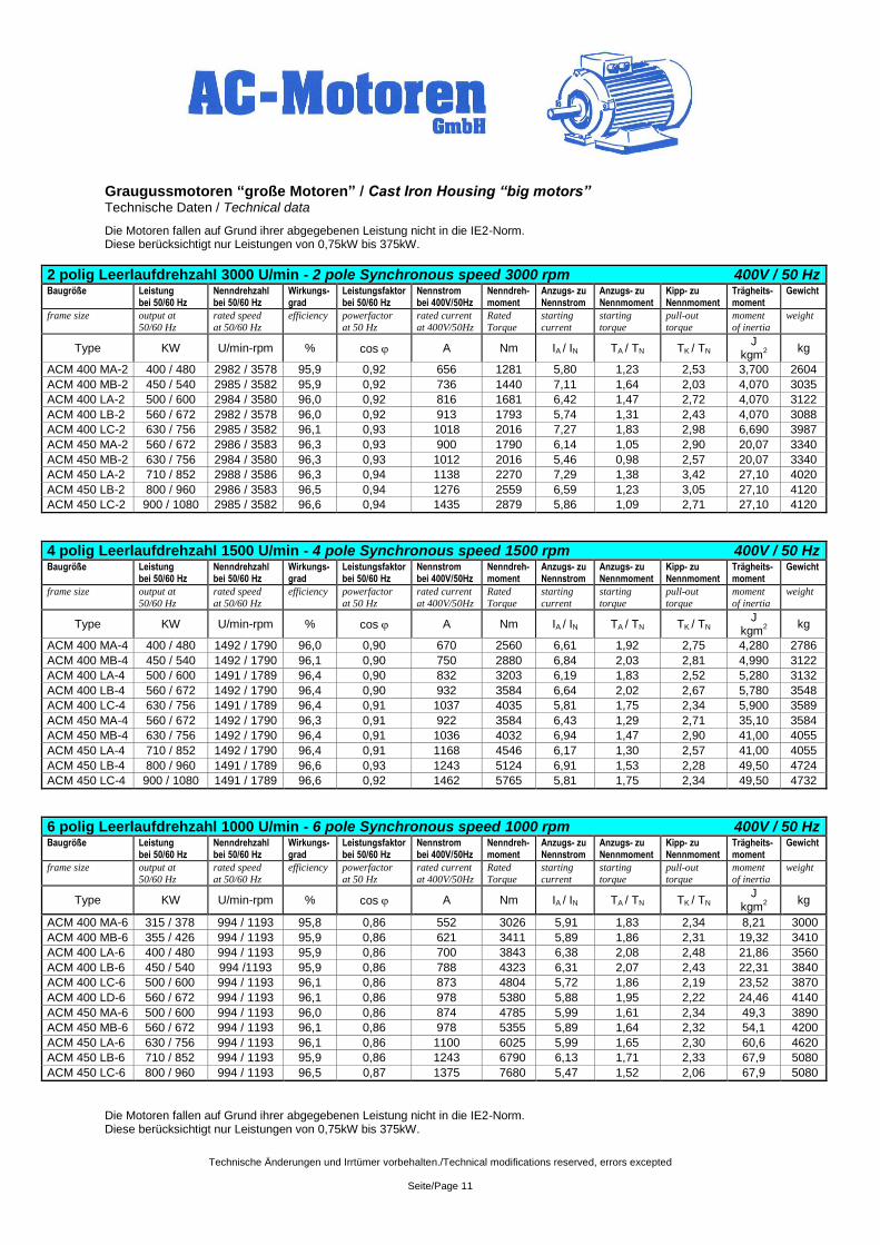
Graugussmotoren “große Motoren” / Cast Iron Housing “big motors” Technische Daten / Technical data
Die Motoren fallen auf Grund ihrer abgegebenen Leistung nicht in die IE2-Norm. Diese berücksichtigt nur Leistungen von 0,75kW bis 375kW.
2 polig Leerlaufdrehzahl 3000 U/min - 2 pole Synchronous speed 3000 rpm 400V / 50 Hz
Baugröße Leistung bei 50/60 Hz
Nenndrehzahl bei 50/60 Hz
Wirkungs-grad
Leistungsfaktor bei 50/60 Hz
Nennstrom bei 400V/50Hz
Nenndreh-moment
Anzugs- zu Nennstrom
Anzugs- zu Nennmoment
Kipp- zu Nennmoment
Trägheits-moment
Gewicht
frame size
output at
50/60 Hz
rated speed
at 50/60 Hz
efficiency powerfactor
at 50 Hz
rated current
at 400V/50Hz
Rated
Torque
starting
current
starting
torque
pull-out
torque
moment
of inertia
weight
Type KW U/min-rpm % cos A Nm IA / IN TA / TN TK / TN J
kgm2
kg
ACM 400 MA-2 400 / 480 2982 / 3578 95,9 0,92 656 1281 5,80 1,23 2,53 3,700 2604
ACM 400 MB-2 450 / 540 2985 / 3582 95,9 0,92 736 1440 7,11 1,64 2,03 4,070 3035
ACM 400 LA-2 500 / 600 2984 / 3580 96,0 0,92 816 1681 6,42 1,47 2,72 4,070 3122
ACM 400 LB-2 560 / 672 2982 / 3578 96,0 0,92 913 1793 5,74 1,31 2,43 4,070 3088
ACM 400 LC-2 630 / 756 2985 / 3582 96,1 0,93 1018 2016 7,27 1,83 2,98 6,690 3987
ACM 450 MA-2 560 / 672 2986 / 3583 96,3 0,93 900 1790 6,14 1,05 2,90 20,07 3340
ACM 450 MB-2 630 / 756 2984 / 3580 96,3 0,93 1012 2016 5,46 0,98 2,57 20,07 3340
ACM 450 LA-2 710 / 852 2988 / 3586 96,3 0,94 1138 2270 7,29 1,38 3,42 27,10 4020
ACM 450 LB-2 800 / 960 2986 / 3583 96,5 0,94 1276 2559 6,59 1,23 3,05 27,10 4120
ACM 450 LC-2 900 / 1080 2985 / 3582 96,6 0,94 1435 2879 5,86 1,09 2,71 27,10 4120
4 polig Leerlaufdrehzahl 1500 U/min - 4 pole Synchronous speed 1500 rpm 400V / 50 Hz Baugröße Leistung
bei 50/60 Hz Nenndrehzahl bei 50/60 Hz
Wirkungs-grad
Leistungsfaktor bei 50/60 Hz
Nennstrom bei 400V/50Hz
Nenndreh-moment
Anzugs- zu Nennstrom
Anzugs- zu Nennmoment
Kipp- zu Nennmoment
Trägheits-moment
Gewicht
frame size
output at
50/60 Hz
rated speed
at 50/60 Hz
efficiency powerfactor
at 50 Hz
rated current
at 400V/50Hz
Rated
Torque
starting
current
starting
torque
pull-out
torque
moment
of inertia
weight
Type KW U/min-rpm % cos A Nm IA / IN TA / TN TK / TN J
kgm2
kg
ACM 400 MA-4 400 / 480 1492 / 1790 96,0 0,90 670 2560 6,61 1,92 2,75 4,280 2786
ACM 400 MB-4 450 / 540 1492 / 1790 96,1 0,90 750 2880 6,84 2,03 2,81 4,990 3122
ACM 400 LA-4 500 / 600 1491 / 1789 96,4 0,90 832 3203 6,19 1,83 2,52 5,280 3132
ACM 400 LB-4 560 / 672 1492 / 1790 96,4 0,90 932 3584 6,64 2,02 2,67 5,780 3548
ACM 400 LC-4 630 / 756 1491 / 1789 96,4 0,91 1037 4035 5,81 1,75 2,34 5,900 3589
ACM 450 MA-4 560 / 672 1492 / 1790 96,3 0,91 922 3584 6,43 1,29 2,71 35,10 3584
ACM 450 MB-4 630 / 756 1492 / 1790 96,4 0,91 1036 4032 6,94 1,47 2,90 41,00 4055
ACM 450 LA-4 710 / 852 1492 / 1790 96,4 0,91 1168 4546 6,17 1,30 2,57 41,00 4055
ACM 450 LB-4 800 / 960 1491 / 1789 96,6 0,93 1243 5124 6,91 1,53 2,28 49,50 4724
ACM 450 LC-4 900 / 1080 1491 / 1789 96,6 0,92 1462 5765 5,81 1,75 2,34 49,50 4732
6 polig Leerlaufdrehzahl 1000 U/min - 6 pole Synchronous speed 1000 rpm 400V / 50 Hz
Baugröße Leistung bei 50/60 Hz
Nenndrehzahl bei 50/60 Hz
Wirkungs-grad
Leistungsfaktor bei 50/60 Hz
Nennstrom bei 400V/50Hz
Nenndreh-moment
Anzugs- zu Nennstrom
Anzugs- zu Nennmoment
Kipp- zu Nennmoment
Trägheits-moment
Gewicht
frame size
output at
50/60 Hz
rated speed
at 50/60 Hz
efficiency powerfactor
at 50 Hz
rated current
at 400V/50Hz
Rated
Torque
starting
current
starting
torque
pull-out
torque
moment
of inertia
weight
Type KW U/min-rpm % cos A Nm IA / IN TA / TN TK / TN J
kgm2
kg
ACM 400 MA-6 315 / 378 994 / 1193 95,8 0,86 552 3026 5,91 1,83 2,34 8,21 3000
ACM 400 MB-6 355 / 426 994 / 1193 95,9 0,86 621 3411 5,89 1,86 2,31 19,32 3410
ACM 400 LA-6 400 / 480 994 / 1193 95,9 0,86 700 3843 6,38 2,08 2,48 21,86 3560
ACM 400 LB-6 450 / 540 994 /1193 95,9 0,86 788 4323 6,31 2,07 2,43 22,31 3840
ACM 400 LC-6 500 / 600 994 / 1193 96,1 0,86 873 4804 5,72 1,86 2,19 23,52 3870
ACM 400 LD-6 560 / 672 994 / 1193 96,1 0,86 978 5380 5,88 1,95 2,22 24,46 4140
ACM 450 MA-6 500 / 600 994 / 1193 96,0 0,86 874 4785 5,99 1,61 2,34 49,3 3890
ACM 450 MB-6 560 / 672 994 / 1193 96,1 0,86 978 5355 5,89 1,64 2,32 54,1 4200
ACM 450 LA-6 630 / 756 994 / 1193 96,1 0,86 1100 6025 5,99 1,65 2,30 60,6 4620
ACM 450 LB-6 710 / 852 994 / 1193 95,9 0,86 1243 6790 6,13 1,71 2,33 67,9 5080
ACM 450 LC-6 800 / 960 994 / 1193 96,5 0,87 1375 7680 5,47 1,52 2,06 67,9 5080
Die Motoren fallen auf Grund ihrer abgegebenen Leistung nicht in die IE2-Norm. Diese berücksichtigt nur Leistungen von 0,75kW bis 375kW.
Technische Änderungen und Irrtümer vorbehalten./Technical modifications reserved, errors excepted
Seite/Page 12
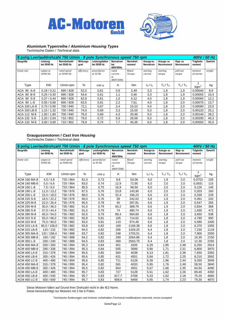
Aluminium Typenreihe / Aluminium Housing Types Technische Daten / Technical data
8 polig Leerlaufdrehzahl 750 U/min - 8 pole Synchronous speed 750 rpm 400V / 50 Hz Baugröße Leistung
bei 50/60 Hz Nenndrehzahl bei 50/60 Hz
Wirkungs-grad
Leistungsfaktor bei 50/60 Hz
Nennstrom bei 400V/50Hz
Nenndreh-moment
Anzugs-zu Nennstrom
Anzugs- zu Nennmoment
Kipp- zu Nennmoment
Trägheits-moment
Gewicht
frame size
output at
50/60 Hz
rated speed
at 50/60 Hz
efficiency powerfactor
at 50 Hz
rated
current
at
400V/50Hz
Rated
Torque
starting
current
starting
torque
pull-out
torque
moment
of inertia
weight
Type KW U/min-rpm % cos A Nm IA / IN TA / TN TK / TN J
kgm2
kg
ACA 80 A-8 0,18 / 0,21 690 / 828 52,0 0,61 0,9 2,49 3,3 1,8 1,9 0,00040 8,9
ACA 80 B-8 0,25 / 0,30 690 / 828 54,6 0,61 1,1 3,46 3,3 1,8 1,9 0,00055 10,4
ACA 90 S-8 0,37 / 0,44 690 / 828 62,8 0,61 1,5 5,12 4,0 1,8 1,9 0,00060 12,1
ACA 90 L-8 0,55 / 0,66 690 / 828 63,5 0,61 2,2 7,61 4,0 1,8 2,0 0,00075 13,7
ACA 100 LA-8 0,75 / 0,90 700 / 840 72,1 0,67 2,4 10,23 4,0 1,8 2,0 0,00090 23,0
ACA 100 LB-8 1,10 / 1,32 700 / 840 74,0 0,69 3,3 15,00 5,0 1,8 2,0 0,00120 25,1
ACA 112 M-8 1,50 / 1,80 700 / 840 76,0 0,69 4,3 20,46 5,0 1,8 2,0 0,00140 28,2
ACA 132 S-8 2,20 / 2,64 710 / 852 79,0 0,72 5,9 29,59 6,0 1,8 2,0 0,00290 40,3
ACA 132 M-8 3,00 / 3,60 710 / 852 79,9 0,74 7,7 40,35 6,0 1,8 2,0 0,00550 45,0
Graugussmotoren / Cast Iron Housing Technische Daten / Technical data
8 polig Leerlaufdrehzahl 750 U/min - 8 pole Synchronous speed 750 rpm 400V / 50 Hz Baugröße Leistung
bei 50/60 Hz Nenndrehzahl bei 50/60 Hz
Wirkungs-grad
Leistungsfaktor bei 50/60 Hz
Nennstrom bei 400V/50Hz
Nenndreh-moment
Anzugs-zu Nennstrom
Anzugs- zu Nennmoment
Kipp- zu Nennmoment
Trägheits-moment
Gewicht
frame size
output at
50/60 Hz
rated speed
at 50/60 Hz
efficiency powerfactor
at 50 Hz
rated
current
at
400V/50Hz
Rated
Torque
starting
current
starting
torque
pull-out
torque
moment
of inertia
weight
Type KW U/min-rpm % cos A Nm IA / IN TA / TN TK / TN J
kgm2
kg
ACM 160 MA-8 4,0 / 4,8 720 / 864 81,0 0,73 9,8 53,06 6,0 1,9 2,0 0,0753 105
ACM 160 MB-8 5,5 / 6,6 720 / 864 83,0 0,74 12,9 72,95 6,0 2,0 2,0 0,0931 115
ACM 160 L-8 7,5 / 9,0 720 / 864 85,5 0,75 16,9 99,50 6,0 2,0 2,0 0,126 145
ACM 180 L-8 11,0 / 13,2 730 / 876 87,5 0,76 23,8 143,90 6,0 2,0 2,0 0,203 160
ACM 200 L-8 15,0 / 18,0 730 / 876 88,0 0,76 32,4 196,23 6,6 2,0 2,0 0,339 228
ACM 225 S-8 18,5 / 22,2 730 / 876 90,0 0,76 39 242,02 6,6 1,9 2,0 0,491 242
ACM 225 M-8 22,0 / 26,4 730 / 876 90,5 0,78 45 287,81 6,6 1,9 2,0 0,547 265
ACM 250 M-8 30,0 / 36,0 735 / 882 91,0 0,79 60,2 389,79 6,6 1,9 2,0 0,834 368
ACM 280 S-8 37,0 / 44,4 735 / 882 91,5 0,79 74 480,74 6,6 1,9 2,0 1,930 472
ACM 280 M-8 45,0 / 54,0 735 / 882 92,0 0,79 89,4 584,69 6,6 1,8 2,0 3,650 538
ACM 315 S-8 55,0 / 66,0 735 / 882 92,8 0,81 105 714,62 6,6 1,8 2,0 4,790 900
ACM 315 M-8 75,0 / 90,0 735 / 882 93,0 0,81 143 974,48 6,6 1,8 2,0 5,580 1000
ACM 315 LA-8 90,0 / 108,0 735 / 882 93,8 0,82 169 1169,38 6,6 1,8 2,0 6,370 1055
ACM 315 LB-8 110 / 132 735 / 882 94,0 0,82 206 1429,25 6,4 1,8 2,0 7,230 1118
ACM 355 MA-8 132 / 158,4 740 / 888 93,7 0,82 248 1703,51 6,4 1,8 2,0 7,900 2000
ACM 355 MB-8 160 / 192 740 / 888 94,2 0,82 299 2064,86 6,4 1,8 2,0 10,30 2150
ACM 355 L-8 200 / 240 740 / 888 94,5 0,83 369 2563,75 6,4 1,8 2,0 12,30 2250
ACM 400 MA-8 250 / 300 745 / 894 95,3 0,84 451 3205 6,29 1,85 2,48 6,250 2914
ACM 400 MB-8 280 / 336 745 / 894 95,3 0,84 505 3589 5,90 1,71 2,31 6,800 3970
ACM 400 LA-8 315 / 378 745 / 894 95,5 0,85 560 4038 6,13 1,81 2,38 7,650 3392
ACM 400 LB-8 355 / 426 745 / 894 95,6 0,85 631 4551 5,84 1,72 2,25 8,210 3592
ACM 400 LC-8 400 / 480 745 / 894 95,6 0,85 711 5128 6,39 1,96 2,44 9,260 3949
ACM 450 MA-8 315 / 378 746 / 895 95,4 0,82 581 4033 5,95 1,76 2,49 59,50 3840
ACM 450 MB-8 355 / 426 745 / 894 95,5 0,82 654 4551 5,67 1,66 2,35 64,50 4090
ACM 450 LA-8 400 / 480 745 / 894 95,7 0,83 727 5128 5,51 1,62 2,26 69,40 4350
ACM 450 LB-8 450 / 540 745 / 894 95,7 0,83 817,7 5768 5,43 1,62 2,18 75,20 4660
ACM 450 LC-8 500 / 600 745 / 894 95,7 0,83 908,6 6409 5,65 1,74 2,23 79,30 4870
Diese Motoren fallen auf Grund ihrer Drehzahl nicht in die IE2-Norm. Diese berücksichtigt nur Motoren mit 2 bis 6 Polen.
Technische Änderungen und Irrtümer vorbehalten./Technical modifications reserved, errors excepted
Seite/Page 13
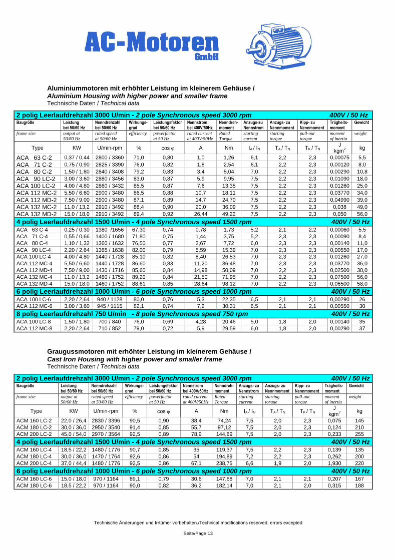
Aluminiummotoren mit erhöhter Leistung im kleinerem Gehäuse / Aluminium Housing with higher power and smaller frame Technische Daten / Technical data
2 polig Leerlaufdrehzahl 3000 U/min - 2 pole Synchronous speed 3000 rpm 400V / 50 Hz Baugröße Leistung
bei 50/60 Hz Nenndrehzahl bei 50/60 Hz
Wirkungs-grad
Leistungsfaktor bei 50/60 Hz
Nennstrom bei 400V/50Hz
Nenndreh-moment
Anzugs-zu Nennstrom
Anzugs- zu Nennmoment
Kipp- zu Nennmoment
Trägheits-moment
Gewicht
frame size
output at
50/60 Hz
rated speed
at 50/60 Hz
efficiency powerfactor
at 50 Hz
rated current
at 400V/50Hz
Rated
Torque
starting
current
starting
torque
pull-out
torque
moment
of inertia
weight
Type KW U/min-rpm % cos A Nm IA / IN TA / TN TK / TN J
kgm2
kg
ACA 63 C-2 0,37 / 0,44 2800 / 3360 71,0 0,80 1,0 1,26 6,1 2,2 2,3 0,00075 5,5
ACA 71 C-2 0,75 / 0,90 2825 / 3390 76,0 0,82 1,8 2,54 6,1 2,2 2,3 0,00120 8,0
ACA 80 C-2 1,50 / 1,80 2840 / 3408 79,2 0,83 3,4 5,04 7,0 2,2 2,3 0,00290 10,8
ACA 90 LC-2 3,00 / 3,60 2880 / 3456 83,0 0,87 5,9 9,95 7,5 2,2 2,3 0,01090 18,0
ACA 100 LC-2 4,00 / 4,80 2860 / 3432 85,5 0,87 7,6 13,35 7,5 2,2 2.3 0,01260 25,0
ACA 112 MC-2 5,50 / 6,60 2900 / 3480 86,5 0,88 10,7 18,11 7,5 2,2 2,3 0,03770 34,0
ACA 112 MD-2 7,50 / 9,00 2900 / 3480 87,1 0,89 14,7 24,70 7,5 2,2 2,3 0,04990 39,0
ACA 132 MC-2 11,0 / 13,2 2910 / 3492 88,4 0,90 20,0 36,09 7,5 2,2 2,3 0,038 49,0
ACA 132 MD-2 15,0 / 18,0 2910 / 3492 89,4 0,92 26,44 49,22 7,5 2,2 2,3 0,050 56,0
4 polig Leerlaufdrehzahl 1500 U/min - 4 pole Synchronous speed 1500 rpm 400V / 50 Hz ACA 63 C-4 0,25 / 0,30 1380 /1656 67,30 0,74 0,78 1,73 5,2 2,1 2,2 0,00060 5,5
ACA 71 C-4 0,55 / 0,66 1400 / 1680 71,80 0,75 1,44 3,75 5,2 2,3 2,3 0,00090 8,4
ACA 80 C-4 1,10 / 1,32 1360 / 1632 76,50 0,77 2,67 7,72 6,0 2,3 2,3 0,00140 11,0
ACA 90 LC-4 2,20 / 2,64 1365 / 1638 82,00 0,79 5,59 15,39 7,0 2,3 2,3 0,00550 17,0
ACA 100 LC-4 4,00 / 4,80 1440 / 1728 85,10 0,82 8,40 26,53 7,0 2,3 2,3 0,01260 27,0
ACA 112 MC-4 5,50 / 6,60 1440 / 1728 86,60 0,83 11,20 36,48 7,0 2,3 2,3 0,03770 36,0
ACA 112 MD-4 7,50 / 9,00 1430 / 1716 85,60 0,84 14,98 50,09 7,0 2,2 2,3 0,02500 30,0
ACA 132 MC-4 11,0 / 13,2 1460 / 1752 89,20 0,84 21,50 71,95 7,0 2,2 2,3 0,07500 56,0
ACA 132 MD-4 15,0 / 18,0 1460 / 1752 88,61 0,85 28,64 98,12 7,0 2,2 2,3 0,06500 58,0
6 polig Leerlaufdrehzahl 1000 U/min - 6 pole Synchronous speed 1000 rpm 400V / 50 Hz ACA 100 LC-6 2,20 / 2,64 940 / 1128 80,0 0,76 5,3 22,35 6,5 2,1 2,1 0,00290 26
ACA 112 MC-6 3,00 / 3,60 945 / 1115 82,1 0,74 7,2 30,31 6,5 2,1 2,1 0,00550 30
8 polig Leerlaufdrehzahl 750 U/min - 8 pole Synchronous speed 750 rpm 400V / 50 Hz ACA 100 LC-8 1,50 / 1,80 700 / 840 76,0 0,69 4,28 20,46 5,0 1,8 2,0 0,00140 35
ACA 112 MC-8 2,20 / 2,64 710 / 852 79,0 0,72 5,9 29,59 6,0 1,8 2,0 0,00290 37
Graugussmotoren mit erhöhter Leistung im kleinerem Gehäuse / Cast Iron Housing with higher power and smaller frame Technische Daten / Technical data
2 polig Leerlaufdrehzahl 3000 U/min - 2 pole Synchronous speed 3000 rpm 400V / 50 Hz
Baugröße Leistung bei 50/60 Hz
Nenndrehzahl bei 50/60 Hz
Wirkungs-grad
Leistungsfaktor bei 50/60 Hz
Nennstrom bei 400V/50Hz
Nenndreh-moment
Anzugs- zu Nennstrom
Anzugs- zu Nennmoment
Kipp- zu Nennmoment
Trägheits-moment
Gewicht
frame size
output at
50/60 Hz
rated speed
at 50/60 Hz
efficiency powerfactor
at 50 Hz
rated current
at 400V/50Hz
Rated
Torque
starting
current
starting
torque
pull-out
torque
moment
of inertia
weight
Type KW U/min-rpm % cos A Nm IA / IN TA / TN TK / TN J
kgm2
kg
ACM 160 LC-2 22,0 / 26,4 2830 / 3396 90,5 0,90 38,4 74,24 7,5 2,0 2,3 0,075 145
ACM 180 LC-2 30,0 / 36,0 2950 / 3540 91,4 0,85 55,7 97,12 7,5 2,0 2,3 0,124 210
ACM 200 LC-2 45,0 / 54,0 2970 / 3564 92,5 0,89 78,9 144,69 7,5 2,0 2,3 0,233 255
4 polig Leerlaufdrehzahl 1500 U/min - 4 pole Synchronous speed 1500 rpm 400V / 50 Hz ACM 160 LC-4 18,5 / 22,2 1480 / 1776 90,7 0,85 35 119,37 7,5 2,2 2,3 0,139 135
ACM 180 LC-4 30,0 / 36,0 1470 / 1764 92,6 0,86 54 194,89 7,2 2,2 2,3 0,262 200
ACM 200 LC-4 37,0 / 44,4 1480 / 1776 92,5 0,86 67,1 238,75 6,6 1,9 2,0 1,930 220
6 polig Leerlaufdrehzahl 1000 U/min - 6 pole Synchronous speed 1000 rpm 400V / 50 Hz
ACM 160 LC-6 15,0 / 18,0 970 / 1164 89,1 0,79 30,6 147,68 7,0 2,1 2,1 0,207 167
ACM 180 LC-6 18,5 / 22,2 970 / 1164 90,0 0,82 36,2 182,14 7,0 2,1 2,0 0,315 188
Technische Änderungen und Irrtümer vorbehalten./Technical modifications reserved, errors excepted
Seite/Page 14
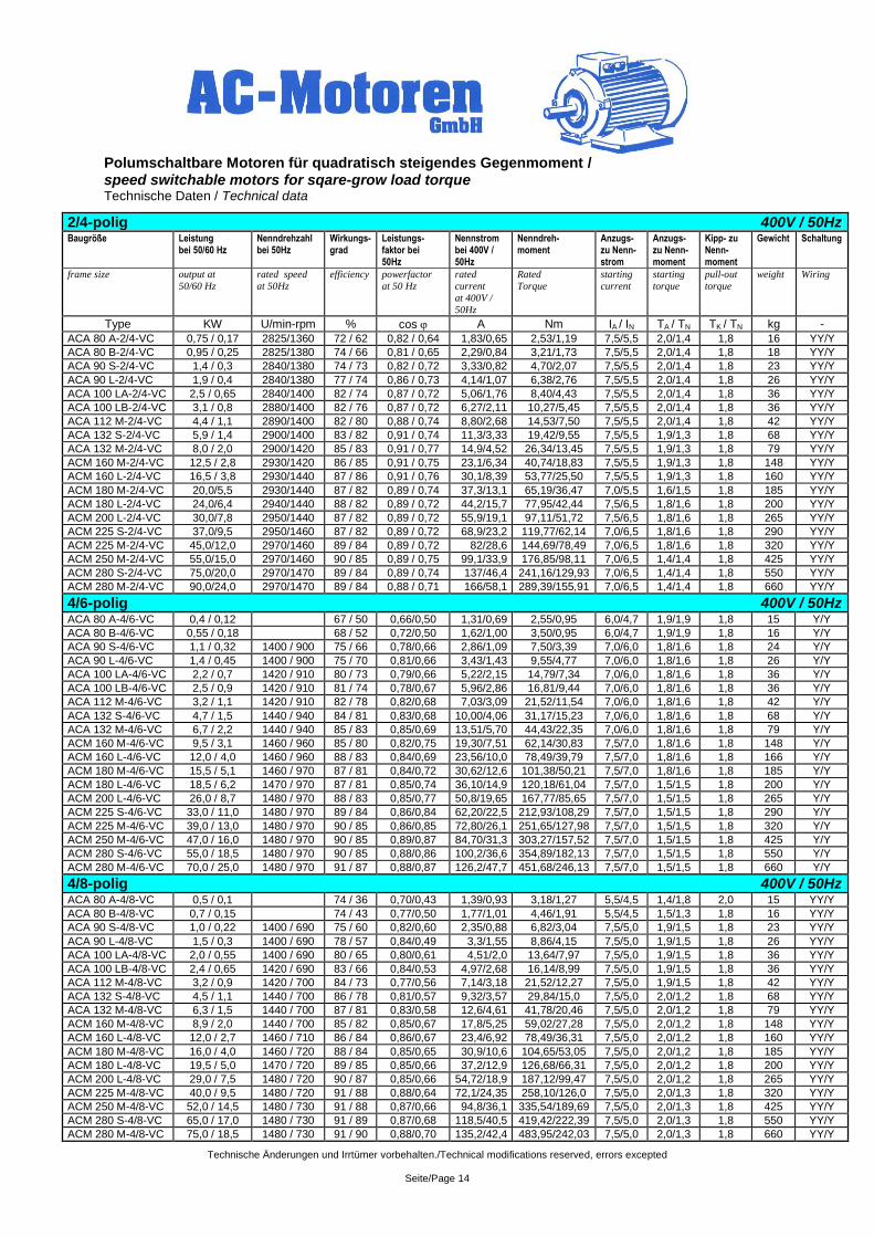
Polumschaltbare Motoren für quadratisch steigendes Gegenmoment / speed switchable motors for sqare-grow load torque Technische Daten / Technical data
2/4-polig 400V / 50Hz Baugröße Leistung
bei 50/60 Hz Nenndrehzahl bei 50Hz
Wirkungs-grad
Leistungs-faktor bei 50Hz
Nennstrom bei 400V / 50Hz
Nenndreh-moment
Anzugs-zu Nenn- strom
Anzugs- zu Nenn- moment
Kipp- zu Nenn-moment
Gewicht Schaltung
frame size
output at
50/60 Hz
rated speed
at 50Hz
efficiency powerfactor
at 50 Hz
rated
current
at 400V /
50Hz
Rated
Torque
starting
current
starting
torque
pull-out
torque
weight
Wiring
Type KW U/min-rpm % cos A Nm IA / IN TA / TN TK / TN kg -
ACA 80 A-2/4-VC 0,75 / 0,17 2825/1360 72 / 62 0,82 / 0,64 1,83/0,65 2,53/1,19 7,5/5,5 2,0/1,4 1,8 16 YY/Y
ACA 80 B-2/4-VC 0,95 / 0,25 2825/1380 74 / 66 0,81 / 0,65 2,29/0,84 3,21/1,73 7,5/5,5 2,0/1,4 1,8 18 YY/Y ACA 90 S-2/4-VC 1,4 / 0,3 2840/1380 74 / 73 0,82 / 0,72 3,33/0,82 4,70/2,07 7,5/5,5 2,0/1,4 1,8 23 YY/Y
ACA 90 L-2/4-VC 1,9 / 0,4 2840/1380 77 / 74 0,86 / 0,73 4,14/1,07 6,38/2,76 7,5/5,5 2,0/1,4 1,8 26 YY/Y ACA 100 LA-2/4-VC 2,5 / 0,65 2840/1400 82 / 74 0,87 / 0,72 5,06/1,76 8,40/4,43 7,5/5,5 2,0/1,4 1,8 36 YY/Y ACA 100 LB-2/4-VC 3,1 / 0,8 2880/1400 82 / 76 0,87 / 0,72 6,27/2,11 10,27/5,45 7,5/5,5 2,0/1,4 1,8 36 YY/Y ACA 112 M-2/4-VC 4,4 / 1,1 2890/1400 82 / 80 0,88 / 0,74 8,80/2,68 14,53/7,50 7,5/5,5 2,0/1,4 1,8 42 YY/Y ACA 132 S-2/4-VC 5,9 / 1,4 2900/1400 83 / 82 0,91 / 0,74 11,3/3,33 19,42/9,55 7,5/5,5 1,9/1,3 1,8 68 YY/Y ACA 132 M-2/4-VC 8,0 / 2,0 2900/1420 85 / 83 0,91 / 0,77 14,9/4,52 26,34/13,45 7,5/5,5 1,9/1,3 1,8 79 YY/Y ACM 160 M-2/4-VC 12,5 / 2,8 2930/1420 86 / 85 0,91 / 0,75 23,1/6,34 40,74/18,83 7,5/5,5 1,9/1,3 1,8 148 YY/Y ACM 160 L-2/4-VC 16,5 / 3,8 2930/1440 87 / 86 0,91 / 0,76 30,1/8,39 53,77/25,50 7,5/5,5 1,9/1,3 1,8 160 YY/Y
ACM 180 M-2/4-VC 20,0/5,5 2930/1440 87 / 82 0,89 / 0,74 37,3/13,1 65,19/36,47 7,0/5,5 1,6/1,5 1,8 185 YY/Y ACM 180 L-2/4-VC 24,0/6,4 2940/1440 88 / 82 0,89 / 0,72 44,2/15,7 77,95/42,44 7,5/6,5 1,8/1,6 1,8 200 YY/Y ACM 200 L-2/4-VC 30,0/7,8 2950/1440 87 / 82 0,89 / 0,72 55,9/19,1 97,11/51,72 7,5/6,5 1,8/1,6 1,8 265 YY/Y ACM 225 S-2/4-VC 37,0/9,5 2950/1460 87 / 82 0,89 / 0,72 68,9/23,2 119,77/62,14 7,0/6,5 1,8/1,6 1,8 290 YY/Y ACM 225 M-2/4-VC 45,0/12,0 2970/1460 89 / 84 0,89 / 0,72 82/28,6 144,69/78,49 7,0/6,5 1,8/1,6 1,8 320 YY/Y ACM 250 M-2/4-VC 55,0/15,0 2970/1460 90 / 85 0,89 / 0,75 99,1/33,9 176,85/98,11 7,0/6,5 1,4/1,4 1,8 425 YY/Y ACM 280 S-2/4-VC 75,0/20,0 2970/1470 89 / 84 0,89 / 0,74 137/46,4 241,16/129,93 7,0/6,5 1,4/1,4 1,8 550 YY/Y ACM 280 M-2/4-VC 90,0/24,0 2970/1470 89 / 84 0,88 / 0,71 166/58,1 289,39/155,91 7,0/6,5 1,4/1,4 1,8 660 YY/Y
4/6-polig 400V / 50Hz ACA 80 A-4/6-VC 0,4 / 0,12 67 / 50 0,66/0,50 1,31/0,69 2,55/0,95 6,0/4,7 1,9/1,9 1,8 15 Y/Y
ACA 80 B-4/6-VC 0,55 / 0,18 68 / 52 0,72/0,50 1,62/1,00 3,50/0,95 6,0/4,7 1,9/1,9 1,8 16 Y/Y
ACA 90 S-4/6-VC 1,1 / 0,32 1400 / 900 75 / 66 0,78/0,66 2,86/1,09 7,50/3,39 7,0/6,0 1,8/1,6 1,8 24 Y/Y
ACA 90 L-4/6-VC 1,4 / 0,45 1400 / 900 75 / 70 0,81/0,66 3,43/1,43 9,55/4,77 7,0/6,0 1,8/1,6 1,8 26 Y/Y
ACA 100 LA-4/6-VC 2,2 / 0,7 1420 / 910 80 / 73 0,79/0,66 5,22/2,15 14,79/7,34 7,0/6,0 1,8/1,6 1,8 36 Y/Y
ACA 100 LB-4/6-VC 2,5 / 0,9 1420 / 910 81 / 74 0,78/0,67 5,96/2,86 16,81/9,44 7,0/6,0 1,8/1,6 1,8 36 Y/Y
ACA 112 M-4/6-VC 3,2 / 1,1 1420 / 910 82 / 78 0,82/0,68 7,03/3,09 21,52/11,54 7,0/6,0 1,8/1,6 1,8 42 Y/Y
ACA 132 S-4/6-VC 4,7 / 1,5 1440 / 940 84 / 81 0,83/0,68 10,00/4,06 31,17/15,23 7,0/6,0 1,8/1,6 1,8 68 Y/Y
ACA 132 M-4/6-VC 6,7 / 2,2 1440 / 940 85 / 83 0,85/0,69 13,51/5,70 44,43/22,35 7,0/6,0 1,8/1,6 1,8 79 Y/Y
ACM 160 M-4/6-VC 9,5 / 3,1 1460 / 960 85 / 80 0,82/0,75 19,30/7,51 62,14/30,83 7,5/7,0 1,8/1,6 1,8 148 Y/Y
ACM 160 L-4/6-VC 12,0 / 4,0 1460 / 960 88 / 83 0,84/0,69 23,56/10,0 78,49/39,79 7,5/7,0 1,8/1,6 1,8 166 Y/Y
ACM 180 M-4/6-VC 15,5 / 5,1 1460 / 970 87 / 81 0,84/0,72 30,62/12,6 101,38/50,21 7,5/7,0 1,8/1,6 1,8 185 Y/Y
ACM 180 L-4/6-VC 18,5 / 6,2 1470 / 970 87 / 81 0,85/0,74 36,10/14,9 120,18/61,04 7,5/7,0 1,5/1,5 1,8 200 Y/Y
ACM 200 L-4/6-VC 26,0 / 8,7 1480 / 970 88 / 83 0,85/0,77 50,8/19,65 167,77/85,65 7,5/7,0 1,5/1,5 1,8 265 Y/Y
ACM 225 S-4/6-VC 33,0 / 11,0 1480 / 970 89 / 84 0,86/0,84 62,20/22,5 212,93/108,29 7,5/7,0 1,5/1,5 1,8 290 Y/Y
ACM 225 M-4/6-VC 39,0 / 13,0 1480 / 970 90 / 85 0,86/0,85 72,80/26,1 251,65/127,98 7,5/7,0 1,5/1,5 1,8 320 Y/Y
ACM 250 M-4/6-VC 47,0 / 16,0 1480 / 970 90 / 85 0,89/0,87 84,70/31,3 303,27/157,52 7,5/7,0 1,5/1,5 1,8 425 Y/Y
ACM 280 S-4/6-VC 55,0 / 18,5 1480 / 970 90 / 85 0,88/0,86 100,2/36,6 354,89/182,13 7,5/7,0 1,5/1,5 1,8 550 Y/Y
ACM 280 M-4/6-VC 70,0 / 25,0 1480 / 970 91 / 87 0,88/0,87 126,2/47,7 451,68/246,13 7,5/7,0 1,5/1,5 1,8 660 Y/Y
4/8-polig 400V / 50Hz ACA 80 A-4/8-VC 0,5 / 0,1 74 / 36 0,70/0,43 1,39/0,93 3,18/1,27 5,5/4,5 1,4/1,8 2,0 15 YY/Y ACA 80 B-4/8-VC 0,7 / 0,15 74 / 43 0,77/0,50 1,77/1,01 4,46/1,91 5,5/4,5 1,5/1,3 1,8 16 YY/Y ACA 90 S-4/8-VC 1,0 / 0,22 1400 / 690 75 / 60 0,82/0,60 2,35/0,88 6,82/3,04 7,5/5,0 1,9/1,5 1,8 23 YY/Y
ACA 90 L-4/8-VC 1,5 / 0,3 1400 / 690 78 / 57 0,84/0,49 3,3/1,55 8,86/4,15 7,5/5,0 1,9/1,5 1,8 26 YY/Y ACA 100 LA-4/8-VC 2,0 / 0,55 1400 / 690 80 / 65 0,80/0,61 4,51/2,0 13,64/7,97 7,5/5,0 1,9/1,5 1,8 36 YY/Y ACA 100 LB-4/8-VC 2,4 / 0,65 1420 / 690 83 / 66 0,84/0,53 4,97/2,68 16,14/8,99 7,5/5,0 1,9/1,5 1,8 36 YY/Y ACA 112 M-4/8-VC 3,2 / 0,9 1420 / 700 84 / 73 0,77/0,56 7,14/3,18 21,52/12,27 7,5/5,0 1,9/1,5 1,8 42 YY/Y ACA 132 S-4/8-VC 4,5 / 1,1 1440 / 700 86 / 78 0,81/0,57 9,32/3,57 29,84/15,0 7,5/5,0 2,0/1,2 1,8 68 YY/Y ACA 132 M-4/8-VC 6,3 / 1,5 1440 / 700 87 / 81 0,83/0,58 12,6/4,61 41,78/20,46 7,5/5,0 2,0/1,2 1,8 79 YY/Y ACM 160 M-4/8-VC 8,9 / 2,0 1440 / 700 85 / 82 0,85/0,67 17,8/5,25 59,02/27,28 7,5/5,0 2,0/1,2 1,8 148 YY/Y ACM 160 L-4/8-VC 12,0 / 2,7 1460 / 710 86 / 84 0,86/0,67 23,4/6,92 78,49/36,31 7,5/5,0 2,0/1,2 1,8 160 YY/Y
ACM 180 M-4/8-VC 16,0 / 4,0 1460 / 720 88 / 84 0,85/0,65 30,9/10,6 104,65/53,05 7,5/5,0 2,0/1,2 1,8 185 YY/Y ACM 180 L-4/8-VC 19,5 / 5,0 1470 / 720 89 / 85 0,85/0,66 37,2/12,9 126,68/66,31 7,5/5,0 2,0/1,2 1,8 200 YY/Y ACM 200 L-4/8-VC 29,0 / 7,5 1480 / 720 90 / 87 0,85/0,66 54,72/18,9 187,12/99,47 7,5/5,0 2,0/1,2 1,8 265 YY/Y ACM 225 M-4/8-VC 40,0 / 9,5 1480 / 720 91 / 88 0,88/0,64 72,1/24,35 258,10/126,0 7,5/5,0 2,0/1,3 1,8 320 YY/Y ACM 250 M-4/8-VC 52,0 / 14,5 1480 / 730 91 / 88 0,87/0,66 94,8/36,1 335,54/189,69 7,5/5,0 2,0/1,3 1,8 425 YY/Y ACM 280 S-4/8-VC 65,0 / 17,0 1480 / 730 91 / 89 0,87/0,68 118,5/40,5 419,42/222,39 7,5/5,0 2,0/1,3 1,8 550 YY/Y ACM 280 M-4/8-VC 75,0 / 18,5 1480 / 730 91 / 90 0,88/0,70 135,2/42,4 483,95/242,03 7,5/5,0 2,0/1,3 1,8 660 YY/Y
Technische Änderungen und Irrtümer vorbehalten./Technical modifications reserved, errors excepted
Seite/Page 15
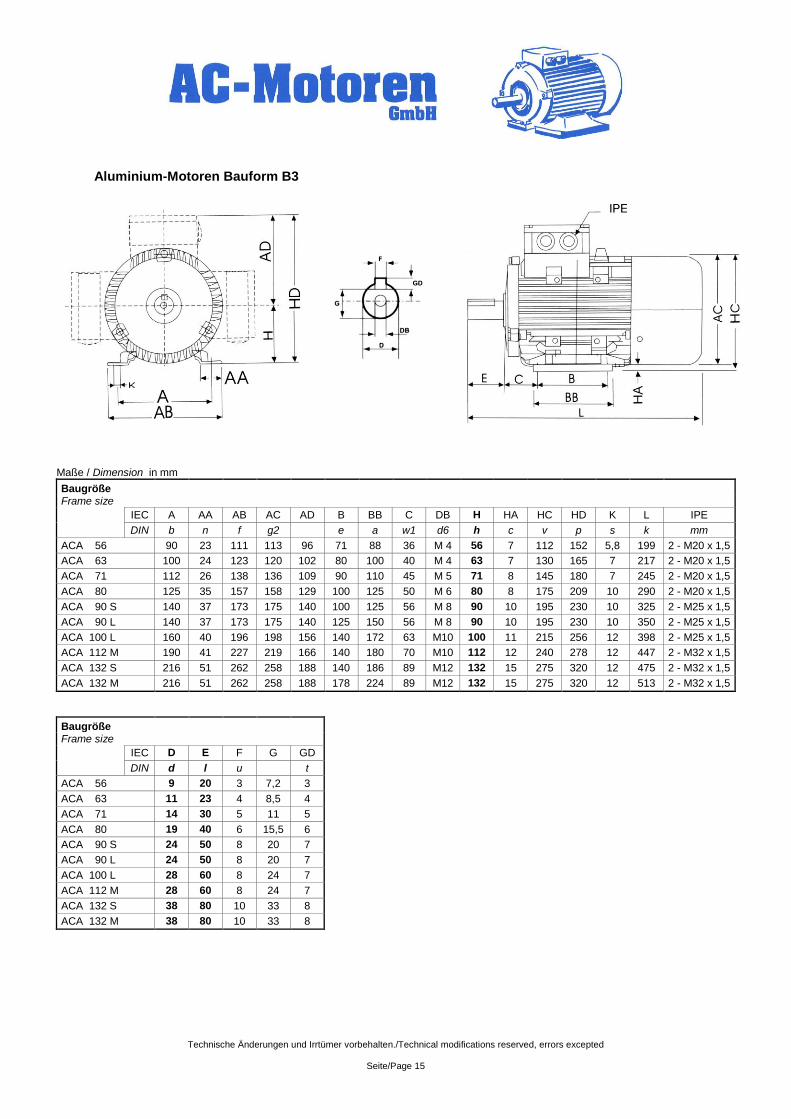
Aluminium-Motoren Bauform B3
Maße / Dimension in mm
Baugröße
Frame size IEC A AA AB AC AD B BB C DB H HA HC HD K L IPE
DIN b n f g2 e a w1 d6 h c v p s k mm
ACA 56 90 23 111 113 96 71 88 36 M 4 56 7 112 152 5,8 199 2 - M20 x 1,5
ACA 63 100 24 123 120 102 80 100 40 M 4 63 7 130 165 7 217 2 - M20 x 1,5
ACA 71 112 26 138 136 109 90 110 45 M 5 71 8 145 180 7 245 2 - M20 x 1,5
ACA 80 125 35 157 158 129 100 125 50 M 6 80 8 175 209 10 290 2 - M20 x 1,5
ACA 90 S 140 37 173 175 140 100 125 56 M 8 90 10 195 230 10 325 2 - M25 x 1,5
ACA 90 L 140 37 173 175 140 125 150 56 M 8 90 10 195 230 10 350 2 - M25 x 1,5
ACA 100 L 160 40 196 198 156 140 172 63 M10 100 11 215 256 12 398 2 - M25 x 1,5
ACA 112 M 190 41 227 219 166 140 180 70 M10 112 12 240 278 12 447 2 - M32 x 1,5
ACA 132 S 216 51 262 258 188 140 186 89 M12 132 15 275 320 12 475 2 - M32 x 1,5
ACA 132 M 216 51 262 258 188 178 224 89 M12 132 15 275 320 12 513 2 - M32 x 1,5
Baugröße Frame size
IEC D E F G GD
DIN d l u t
ACA 56 9 20 3 7,2 3
ACA 63 11 23 4 8,5 4
ACA 71 14 30 5 11 5
ACA 80 19 40 6 15,5 6
ACA 90 S 24 50 8 20 7
ACA 90 L 24 50 8 20 7
ACA 100 L 28 60 8 24 7
ACA 112 M 28 60 8 24 7
ACA 132 S 38 80 10 33 8
ACA 132 M 38 80 10 33 8
Technische Änderungen und Irrtümer vorbehalten./Technical modifications reserved, errors excepted
Seite/Page 16
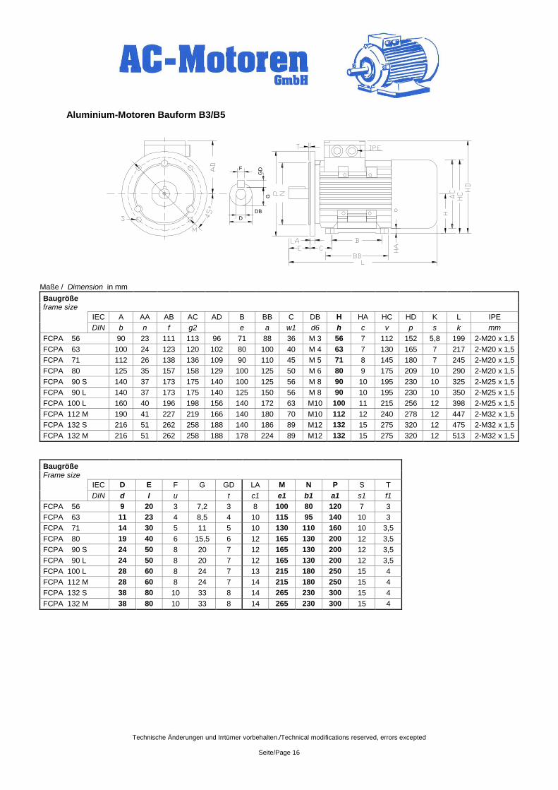
Aluminium-Motoren Bauform B3/B5
Maße / Dimension in mm
Baugröße
frame size
IEC A AA AB AC AD B BB C DB H HA HC HD K L IPE
DIN b n f g2 e a w1 d6 h c v p s k mm
FCPA 56 90 23 111 113 96 71 88 36 M 3 56 7 112 152 5,8 199 2-M20 x 1,5
FCPA 63 100 24 123 120 102 80 100 40 M 4 63 7 130 165 7 217 2-M20 x 1,5
FCPA 71 112 26 138 136 109 90 110 45 M 5 71 8 145 180 7 245 2-M20 x 1,5
FCPA 80 125 35 157 158 129 100 125 50 M 6 80 9 175 209 10 290 2-M20 x 1,5
FCPA 90 S 140 37 173 175 140 100 125 56 M 8 90 10 195 230 10 325 2-M25 x 1,5
FCPA 90 L 140 37 173 175 140 125 150 56 M 8 90 10 195 230 10 350 2-M25 x 1,5
FCPA 100 L 160 40 196 198 156 140 172 63 M10 100 11 215 256 12 398 2-M25 x 1,5
FCPA 112 M 190 41 227 219 166 140 180 70 M10 112 12 240 278 12 447 2-M32 x 1,5
FCPA 132 S 216 51 262 258 188 140 186 89 M12 132 15 275 320 12 475 2-M32 x 1,5
FCPA 132 M 216 51 262 258 188 178 224 89 M12 132 15 275 320 12 513 2-M32 x 1,5
Baugröße
Frame size IEC D E F G GD LA M N P S T
DIN d l u t c1 e1 b1 a1 s1 f1
FCPA 56 9 20 3 7,2 3 8 100 80 120 7 3
FCPA 63 11 23 4 8,5 4 10 115 95 140 10 3
FCPA 71 14 30 5 11 5 10 130 110 160 10 3,5
FCPA 80 19 40 6 15,5 6 12 165 130 200 12 3,5
FCPA 90 S 24 50 8 20 7 12 165 130 200 12 3,5
FCPA 90 L 24 50 8 20 7 12 165 130 200 12 3,5
FCPA 100 L 28 60 8 24 7 13 215 180 250 15 4
FCPA 112 M 28 60 8 24 7 14 215 180 250 15 4
FCPA 132 S 38 80 10 33 8 14 265 230 300 15 4
FCPA 132 M 38 80 10 33 8 14 265 230 300 15 4
DB
D
G
F
GD
Technische Änderungen und Irrtümer vorbehalten./Technical modifications reserved, errors excepted
Seite/Page 17
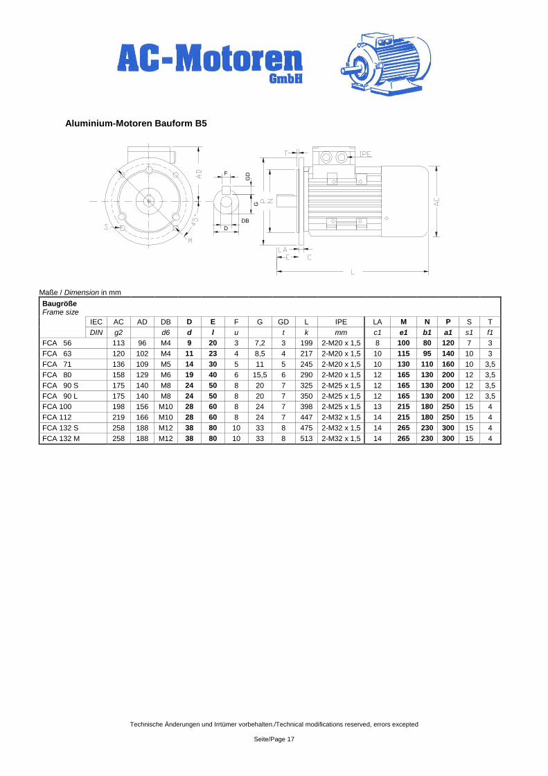
Aluminium-Motoren Bauform B5
Maße / Dimension in mm
Baugröße
Frame size
IEC AC AD DB D E F G GD L IPE LA M N P S T
DIN g2 d6 d l u t k mm c1 e1 b1 a1 s1 f1
FCA 56 113 96 M4 9 20 3 7,2 3 199 2-M20 x 1,5 8 100 80 120 7 3
FCA 63 120 102 M4 11 23 4 8,5 4 217 2-M20 x 1,5 10 115 95 140 10 3
FCA 71 136 109 M5 14 30 5 11 5 245 2-M20 x 1,5 10 130 110 160 10 3,5
FCA 80 158 129 M6 19 40 6 15,5 6 290 2-M20 x 1,5 12 165 130 200 12 3,5
FCA 90 S 175 140 M8 24 50 8 20 7 325 2-M25 x 1,5 12 165 130 200 12 3,5
FCA 90 L 175 140 M8 24 50 8 20 7 350 2-M25 x 1,5 12 165 130 200 12 3,5
FCA 100 198 156 M10 28 60 8 24 7 398 2-M25 x 1,5 13 215 180 250 15 4
FCA 112 219 166 M10 28 60 8 24 7 447 2-M32 x 1,5 14 215 180 250 15 4
FCA 132 S 258 188 M12 38 80 10 33 8 475 2-M32 x 1,5 14 265 230 300 15 4
FCA 132 M 258 188 M12 38 80 10 33 8 513 2-M32 x 1,5 14 265 230 300 15 4
DB
D
G
F
GD
Technische Änderungen und Irrtümer vorbehalten./Technical modifications reserved, errors excepted
Seite/Page 18
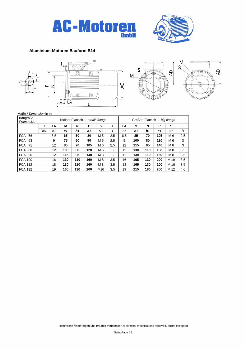
Aluminium-Motoren Bauform B14
Maße / Dimension in mm
Baugröße Frame size
Kleiner Flansch - small flange Großer Flansch - big flange
IEC LA M N P S T LA M N P S T
DIN c1 e1 b1 a1 S1 f c1 e1 b1 a1 s1 f1
FCA 56 8,5 65 50 80 M 5 2,5 8,5 85 70 105 M 6 2,5
FCA 63 9 75 60 90 M 5 2,5 9 100 80 120 M 6 3
FCA 71 12 85 70 105 M 6 2,5 12 115 95 140 M 8 3
FCA 80 12 100 80 120 M 6 3 12 130 110 160 M 8 3,5
FCA 90 12 115 95 140 M 8 3 12 130 110 160 M 8 3,5
FCA 100 16 130 110 160 M 8 3,5 16 165 130 200 M 10 3,5
FCA 112 18 130 110 160 M 8 3,5 18 165 130 200 M 10 3,5
FCA 132 19 165 130 200 M10 3,5 19 215 180 250 M 12 4,0
Technische Änderungen und Irrtümer vorbehalten./Technical modifications reserved, errors excepted
Seite/Page 19
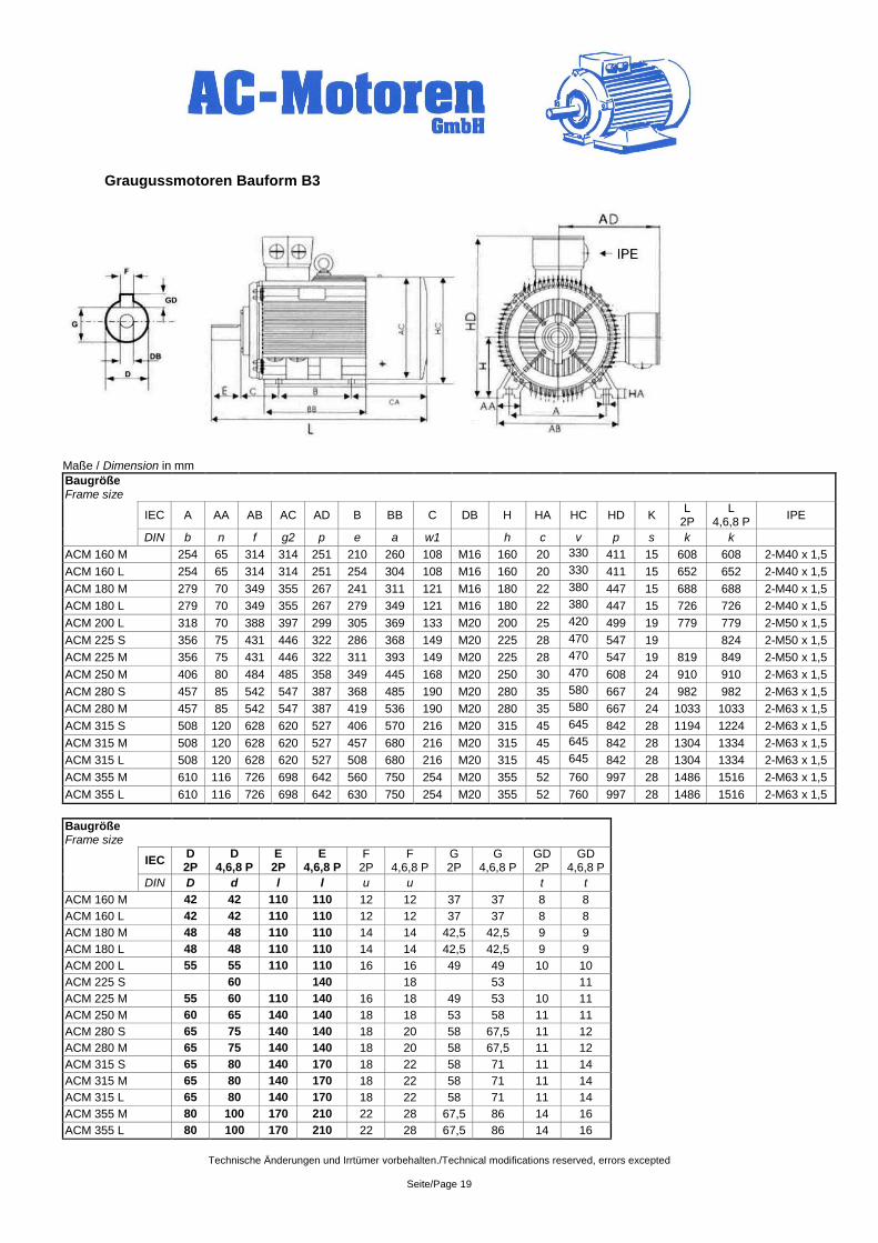
Graugussmotoren Bauform B3
Maße / Dimension in mm
Baugröße Frame size
IEC A AA AB AC AD B BB C DB H HA HC HD K
L 2P
L 4,6,8 P
IPE
DIN b n f g2 p e a w1 h c v p s k k
ACM 160 M 254 65 314 314 251 210 260 108 M16 160 20 330 411 15 608 608 2-M40 x 1,5
ACM 160 L 254 65 314 314 251 254 304 108 M16 160 20 330 411 15 652 652 2-M40 x 1,5
ACM 180 M 279 70 349 355 267 241 311 121 M16 180 22 380 447 15 688 688 2-M40 x 1,5
ACM 180 L 279 70 349 355 267 279 349 121 M16 180 22 380 447 15 726 726 2-M40 x 1,5
ACM 200 L 318 70 388 397 299 305 369 133 M20 200 25 420 499 19 779 779 2-M50 x 1,5
ACM 225 S 356 75 431 446 322 286 368 149 M20 225 28 470 547 19 824 2-M50 x 1,5
ACM 225 M 356 75 431 446 322 311 393 149 M20 225 28 470 547 19 819 849 2-M50 x 1,5
ACM 250 M 406 80 484 485 358 349 445 168 M20 250 30 470 608 24 910 910 2-M63 x 1,5
ACM 280 S 457 85 542 547 387 368 485 190 M20 280 35 580 667 24 982 982 2-M63 x 1,5
ACM 280 M 457 85 542 547 387 419 536 190 M20 280 35 580 667 24 1033 1033 2-M63 x 1,5
ACM 315 S 508 120 628 620 527 406 570 216 M20 315 45 645 842 28 1194 1224 2-M63 x 1,5
ACM 315 M 508 120 628 620 527 457 680 216 M20 315 45 645 842 28 1304 1334 2-M63 x 1,5
ACM 315 L 508 120 628 620 527 508 680 216 M20 315 45 645 842 28 1304 1334 2-M63 x 1,5
ACM 355 M 610 116 726 698 642 560 750 254 M20 355 52 760 997 28 1486 1516 2-M63 x 1,5
ACM 355 L 610 116 726 698 642 630 750 254 M20 355 52 760 997 28 1486 1516 2-M63 x 1,5
Baugröße Frame size
IEC
D 2P
D 4,6,8 P
E 2P
E 4,6,8 P
F 2P
F 4,6,8 P
G 2P
G 4,6,8 P
GD 2P
GD 4,6,8 P
DIN D d l l u u t t
ACM 160 M 42 42 110 110 12 12 37 37 8 8
ACM 160 L 42 42 110 110 12 12 37 37 8 8
ACM 180 M 48 48 110 110 14 14 42,5 42,5 9 9
ACM 180 L 48 48 110 110 14 14 42,5 42,5 9 9
ACM 200 L 55 55 110 110 16 16 49 49 10 10
ACM 225 S 60 140 18 53 11
ACM 225 M 55 60 110 140 16 18 49 53 10 11
ACM 250 M 60 65 140 140 18 18 53 58 11 11
ACM 280 S 65 75 140 140 18 20 58 67,5 11 12
ACM 280 M 65 75 140 140 18 20 58 67,5 11 12
ACM 315 S 65 80 140 170 18 22 58 71 11 14
ACM 315 M 65 80 140 170 18 22 58 71 11 14
ACM 315 L 65 80 140 170 18 22 58 71 11 14
ACM 355 M 80 100 170 210 22 28 67,5 86 14 16
ACM 355 L 80 100 170 210 22 28 67,5 86 14 16
Technische Änderungen und Irrtümer vorbehalten./Technical modifications reserved, errors excepted
Seite/Page 20
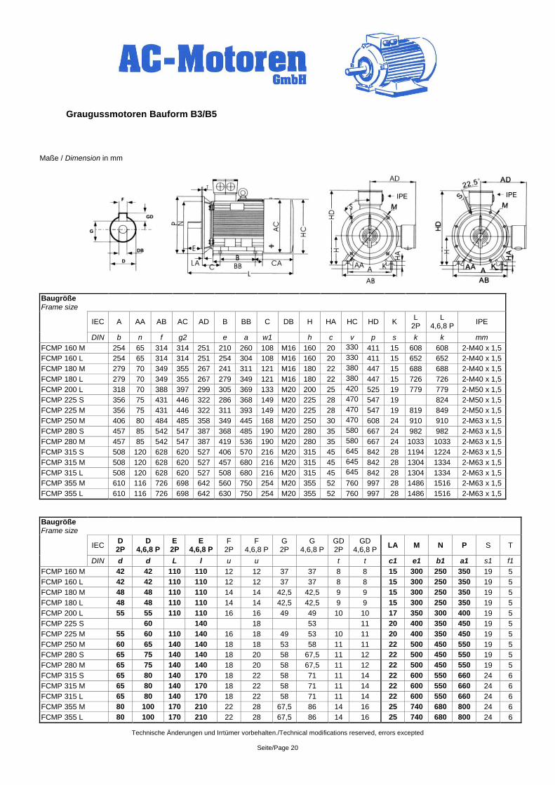
Graugussmotoren Bauform B3/B5
Maße / Dimension in mm
Baugröße Frame size
IEC A AA AB AC AD B BB C DB H HA HC HD K
L 2P
L 4,6,8 P
IPE
DIN b n f g2 e a w1 h c v p s k k mm
FCMP 160 M 254 65 314 314 251 210 260 108 M16 160 20 330 411 15 608 608 2-M40 x 1,5
FCMP 160 L 254 65 314 314 251 254 304 108 M16 160 20 330 411 15 652 652 2-M40 x 1,5
FCMP 180 M 279 70 349 355 267 241 311 121 M16 180 22 380 447 15 688 688 2-M40 x 1,5
FCMP 180 L 279 70 349 355 267 279 349 121 M16 180 22 380 447 15 726 726 2-M40 x 1,5
FCMP 200 L 318 70 388 397 299 305 369 133 M20 200 25 420 525 19 779 779 2-M50 x 1,5
FCMP 225 S 356 75 431 446 322 286 368 149 M20 225 28 470 547 19 824 2-M50 x 1,5
FCMP 225 M 356 75 431 446 322 311 393 149 M20 225 28 470 547 19 819 849 2-M50 x 1,5
FCMP 250 M 406 80 484 485 358 349 445 168 M20 250 30 470 608 24 910 910 2-M63 x 1,5
FCMP 280 S 457 85 542 547 387 368 485 190 M20 280 35 580 667 24 982 982 2-M63 x 1,5
FCMP 280 M 457 85 542 547 387 419 536 190 M20 280 35 580 667 24 1033 1033 2-M63 x 1,5
FCMP 315 S 508 120 628 620 527 406 570 216 M20 315 45 645 842 28 1194 1224 2-M63 x 1,5
FCMP 315 M 508 120 628 620 527 457 680 216 M20 315 45 645 842 28 1304 1334 2-M63 x 1,5
FCMP 315 L 508 120 628 620 527 508 680 216 M20 315 45 645 842 28 1304 1334 2-M63 x 1,5
FCMP 355 M 610 116 726 698 642 560 750 254 M20 355 52 760 997 28 1486 1516 2-M63 x 1,5
FCMP 355 L 610 116 726 698 642 630 750 254 M20 355 52 760 997 28 1486 1516 2-M63 x 1,5
Baugröße Frame size
IEC
D 2P
D 4,6,8 P
E 2P
E 4,6,8 P
F 2P
F 4,6,8 P
G 2P
G 4,6,8 P
GD 2P
GD 4,6,8 P
LA M N P S T
DIN d d L l u u t t c1 e1 b1 a1 s1 f1
FCMP 160 M 42 42 110 110 12 12 37 37 8 8 15 300 250 350 19 5
FCMP 160 L 42 42 110 110 12 12 37 37 8 8 15 300 250 350 19 5
FCMP 180 M 48 48 110 110 14 14 42,5 42,5 9 9 15 300 250 350 19 5
FCMP 180 L 48 48 110 110 14 14 42,5 42,5 9 9 15 300 250 350 19 5
FCMP 200 L 55 55 110 110 16 16 49 49 10 10 17 350 300 400 19 5
FCMP 225 S 60 140 18 53 11 20 400 350 450 19 5
FCMP 225 M 55 60 110 140 16 18 49 53 10 11 20 400 350 450 19 5
FCMP 250 M 60 65 140 140 18 18 53 58 11 11 22 500 450 550 19 5
FCMP 280 S 65 75 140 140 18 20 58 67,5 11 12 22 500 450 550 19 5
FCMP 280 M 65 75 140 140 18 20 58 67,5 11 12 22 500 450 550 19 5
FCMP 315 S 65 80 140 170 18 22 58 71 11 14 22 600 550 660 24 6
FCMP 315 M 65 80 140 170 18 22 58 71 11 14 22 600 550 660 24 6
FCMP 315 L 65 80 140 170 18 22 58 71 11 14 22 600 550 660 24 6
FCMP 355 M 80 100 170 210 22 28 67,5 86 14 16 25 740 680 800 24 6
FCMP 355 L 80 100 170 210 22 28 67,5 86 14 16 25 740 680 800 24 6
Technische Änderungen und Irrtümer vorbehalten./Technical modifications reserved, errors excepted
Seite/Page 21
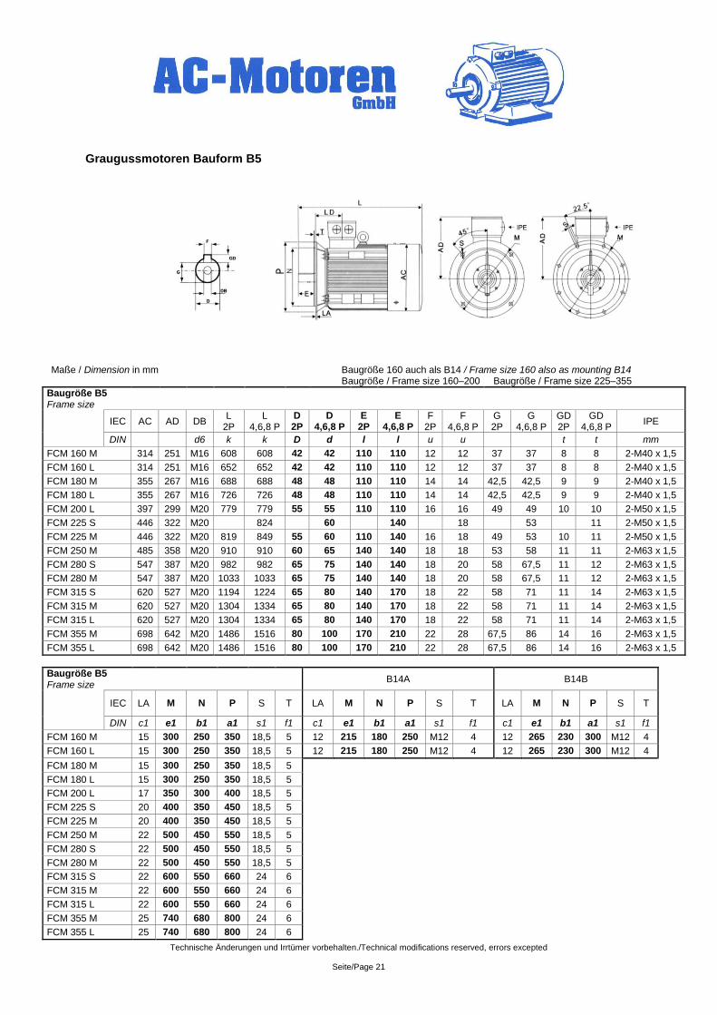
Graugussmotoren Bauform B5
Maße / Dimension in mm Baugröße 160 auch als B14 / Frame size 160 also as mounting B14 Baugröße / Frame size 160–200 Baugröße / Frame size 225–355
Baugröße B5 Frame size
IEC AC AD DB
L 2P
L 4,6,8 P
D 2P
D 4,6,8 P
E 2P
E 4,6,8 P
F 2P
F 4,6,8 P
G 2P
G 4,6,8 P
GD 2P
GD 4,6,8 P
IPE
DIN d6 k k D d l l u u t t mm
FCM 160 M 314 251 M16 608 608 42 42 110 110 12 12 37 37 8 8 2-M40 x 1,5
FCM 160 L 314 251 M16 652 652 42 42 110 110 12 12 37 37 8 8 2-M40 x 1,5
FCM 180 M 355 267 M16 688 688 48 48 110 110 14 14 42,5 42,5 9 9 2-M40 x 1,5
FCM 180 L 355 267 M16 726 726 48 48 110 110 14 14 42,5 42,5 9 9 2-M40 x 1,5
FCM 200 L 397 299 M20 779 779 55 55 110 110 16 16 49 49 10 10 2-M50 x 1,5
FCM 225 S 446 322 M20 824 60 140 18 53 11 2-M50 x 1,5
FCM 225 M 446 322 M20 819 849 55 60 110 140 16 18 49 53 10 11 2-M50 x 1,5
FCM 250 M 485 358 M20 910 910 60 65 140 140 18 18 53 58 11 11 2-M63 x 1,5
FCM 280 S 547 387 M20 982 982 65 75 140 140 18 20 58 67,5 11 12 2-M63 x 1,5
FCM 280 M 547 387 M20 1033 1033 65 75 140 140 18 20 58 67,5 11 12 2-M63 x 1,5
FCM 315 S 620 527 M20 1194 1224 65 80 140 170 18 22 58 71 11 14 2-M63 x 1,5
FCM 315 M 620 527 M20 1304 1334 65 80 140 170 18 22 58 71 11 14 2-M63 x 1,5
FCM 315 L 620 527 M20 1304 1334 65 80 140 170 18 22 58 71 11 14 2-M63 x 1,5
FCM 355 M 698 642 M20 1486 1516 80 100 170 210 22 28 67,5 86 14 16 2-M63 x 1,5
FCM 355 L 698 642 M20 1486 1516 80 100 170 210 22 28 67,5 86 14 16 2-M63 x 1,5
Baugröße B5 Frame size
B14A B14B
IEC LA M N P S T LA M N P S T LA M N P S T
DIN c1 e1 b1 a1 s1 f1 c1 e1 b1 a1 s1 f1 c1 e1 b1 a1 s1 f1
FCM 160 M 15 300 250 350 18,5 5 12 215 180 250 M12 4 12 265 230 300 M12 4
FCM 160 L 15 300 250 350 18,5 5 12 215 180 250 M12 4 12 265 230 300 M12 4
FCM 180 M 15 300 250 350 18,5 5
FCM 180 L 15 300 250 350 18,5 5
FCM 200 L 17 350 300 400 18,5 5
FCM 225 S 20 400 350 450 18,5 5
FCM 225 M 20 400 350 450 18,5 5
FCM 250 M 22 500 450 550 18,5 5
FCM 280 S 22 500 450 550 18,5 5
FCM 280 M 22 500 450 550 18,5 5
FCM 315 S 22 600 550 660 24 6
FCM 315 M 22 600 550 660 24 6
FCM 315 L 22 600 550 660 24 6
FCM 355 M 25 740 680 800 24 6
FCM 355 L 25 740 680 800 24 6
Technische Änderungen und Irrtümer vorbehalten./Technical modifications reserved, errors excepted
Seite/Page 22
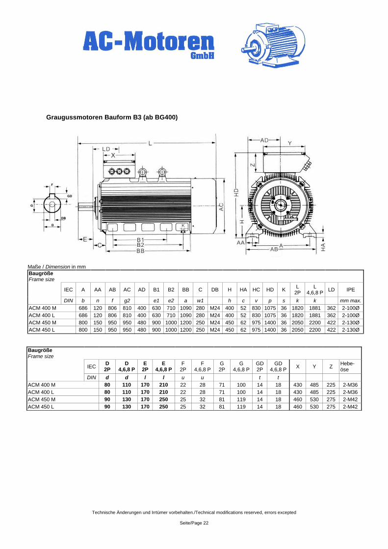
Graugussmotoren Bauform B3 (ab BG400)
Maße / Dimension in mm
Baugröße Frame size
IEC A AA AB AC AD B1 B2 BB C DB H HA HC HD K
L 2P
L 4,6,8 P
LD IPE
DIN b n f g2 e1 e2 a w1 h c v p s k k mm max.
ACM 400 M 686 120 806 810 400 630 710 1090 280 M24 400 52 830 1075 36 1820 1881 362 2-100Ø
ACM 400 L 686 120 806 810 400 630 710 1090 280 M24 400 52 830 1075 36 1820 1881 362 2-100Ø
ACM 450 M 800 150 950 950 480 900 1000 1200 250 M24 450 62 975 1400 36 2050 2200 422 2-130Ø
ACM 450 L 800 150 950 950 480 900 1000 1200 250 M24 450 62 975 1400 36 2050 2200 422 2-130Ø
Baugröße Frame size
IEC
D 2P
D 4,6,8 P
E 2P
E 4,6,8 P
F 2P
F 4,6,8 P
G 2P
G 4,6,8 P
GD 2P
GD 4,6,8 P
X Y Z Hebe-öse
DIN d d l l u u t t
ACM 400 M 80 110 170 210 22 28 71 100 14 18 430 485 225 2-M36
ACM 400 L 80 110 170 210 22 28 71 100 14 18 430 485 225 2-M36
ACM 450 M 90 130 170 250 25 32 81 119 14 18 460 530 275 2-M42
ACM 450 L 90 130 170 250 25 32 81 119 14 18 460 530 275 2-M42
Technische Änderungen und Irrtümer vorbehalten./Technical modifications reserved, errors excepted
Seite/Page 23
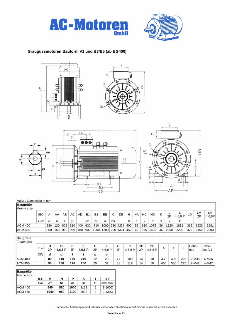
Graugussmotoren Bauform V1 und B3/B5 (ab BG400)
Maße / Dimension in mm
Baugröße Frame size
IEC A AA AB AC AD B1 B2 BB C DB H HA HC HD K
L 2P
L 4,6,8 P
LD LM 2P
LM 4,6,8P
DIN b n f g2 e1 e2 a w1 h c v p s k k
ACM 400 686 120 806 810 400 630 710 1090 280 M24 400 52 830 1075 36 1820 1881 362 1920 1981
ACM 450 800 150 950 950 480 900 1000 1200 250 M24 450 62 975 1400 36 2050 2200 422 2150 2300
Baugröße Frame size
IEC
D 2P
D 4,6,8 P
E 2P
E 4,6,8 P
F 2P
F 4,6,8 P
G 2P
G 4,6,8 P
GD 2P
GD 4,6,8 P
X Y Z Hebe-öse
Hebe-öse V1
DIN d d l l u u t t
ACM 400 80 110 170 210 22 28 71 100 14 18 430 485 225 2-M36 4-M36
ACM 450 90 130 170 250 25 32 81 119 14 18 460 530 275 2-M42 4-M42
Baugröße Frame size
IEC M N P S T IPE
DIN e1 b1 a1 s1 f1 mm max.
ACM 400 940 880 1000 8x28 6 3-100Ø
ACM 450 1040 980 1100 8x32 8 3-130Ø
Technische Änderungen und Irrtümer vorbehalten./Technical modifications reserved, errors excepted
Seite/Page 24
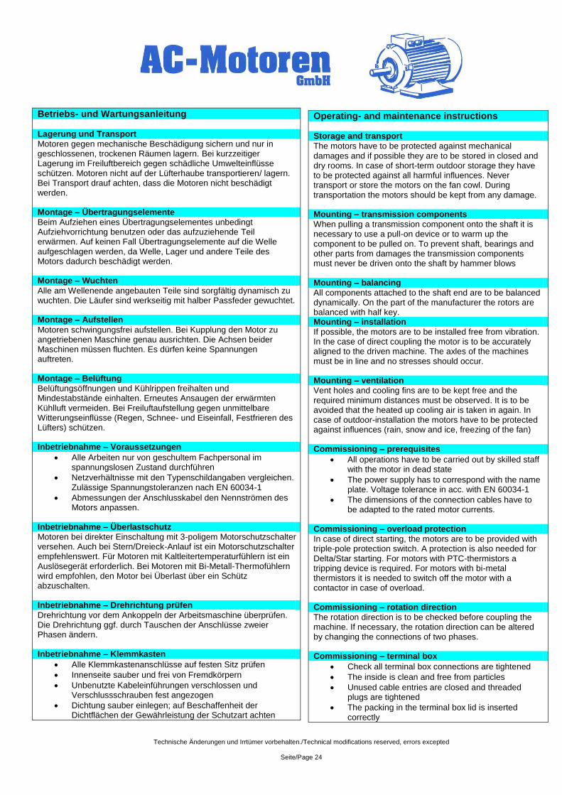
Betriebs- und Wartungsanleitung Lagerung und Transport
Motoren gegen mechanische Beschädigung sichern und nur in geschlossenen, trockenen Räumen lagern. Bei kurzzeitiger Lagerung im Freiluftbereich gegen schädliche Umwelteinflüsse schützen. Motoren nicht auf der Lüfterhaube transportieren/ lagern. Bei Transport drauf achten, dass die Motoren nicht beschädigt werden. Montage – Übertragungselemente
Beim Aufziehen eines Übertragungselementes unbedingt Aufziehvorrichtung benutzen oder das aufzuziehende Teil erwärmen. Auf keinen Fall Übertragungselemente auf die Welle aufgeschlagen werden, da Welle, Lager und andere Teile des Motors dadurch beschädigt werden. Montage – Wuchten
Alle am Wellenende angebauten Teile sind sorgfältig dynamisch zu wuchten. Die Läufer sind werkseitig mit halber Passfeder gewuchtet. Montage – Aufstellen
Motoren schwingungsfrei aufstellen. Bei Kupplung den Motor zu angetriebenen Maschine genau ausrichten. Die Achsen beider Maschinen müssen fluchten. Es dürfen keine Spannungen auftreten. Montage – Belüftung
Belüftungsöffnungen und Kühlrippen freihalten und Mindestabstände einhalten. Erneutes Ansaugen der erwärmten Kühlluft vermeiden. Bei Freiluftaufstellung gegen unmittelbare Witterungseinflüsse (Regen, Schnee- und Eiseinfall, Festfrieren des Lüfters) schützen. Inbetriebnahme – Voraussetzungen
Alle Arbeiten nur von geschultem Fachpersonal im spannungslosen Zustand durchführen
Netzverhältnisse mit den Typenschildangaben vergleichen. Zulässige Spannungstoleranzen nach EN 60034-1
Abmessungen der Anschlusskabel den Nennströmen des Motors anpassen.
Inbetriebnahme – Überlastschutz
Motoren bei direkter Einschaltung mit 3-poligem Motorschutzschalter versehen. Auch bei Stern/Dreieck-Anlauf ist ein Motorschutzschalter empfehlenswert. Für Motoren mit Kaltleitertemperaturfühlern ist ein Auslösegerät erforderlich. Bei Motoren mit Bi-Metall-Thermofühlern wird empfohlen, den Motor bei Überlast über ein Schütz abzuschalten. Inbetriebnahme – Drehrichtung prüfen
Drehrichtung vor dem Ankoppeln der Arbeitsmaschine überprüfen. Die Drehrichtung ggf. durch Tauschen der Anschlüsse zweier Phasen ändern. Inbetriebnahme – Klemmkasten
Alle Klemmkastenanschlüsse auf festen Sitz prüfen
Innenseite sauber und frei von Fremdkörpern
Unbenutzte Kabeleinführungen verschlossen und Verschlussschrauben fest angezogen
Dichtung sauber einlegen; auf Beschaffenheit der Dichtflächen der Gewährleistung der Schutzart achten
Operating- and maintenance instructions Storage and transport
The motors have to be protected against mechanical damages and if possible they are to be stored in closed and dry rooms. In case of short-term outdoor storage they have to be protected against all harmful influences. Never transport or store the motors on the fan cowl. During transportation the motors should be kept from any damage. Mounting – transmission components
When pulling a transmission component onto the shaft it is necessary to use a pull-on device or to warm up the component to be pulled on. To prevent shaft, bearings and other parts from damages the transmission components must never be driven onto the shaft by hammer blows Mounting – balancing
All components attached to the shaft end are to be balanced dynamically. On the part of the manufacturer the rotors are balanced with half key. Mounting – installation
If possible, the motors are to be installed free from vibration. In the case of direct coupling the motor is to be accurately aligned to the driven machine. The axles of the machines must be in line and no stresses should occur. Mounting – ventilation
Vent holes and cooling fins are to be kept free and the required minimum distances must be observed. It is to be avoided that the heated up cooling air is taken in again. In case of outdoor-installation the motors have to be protected against influences (rain, snow and ice, freezing of the fan) Commissioning – prerequisites
All operations have to be carried out by skilled staff with the motor in dead state
The power supply has to correspond with the name plate. Voltage tolerance in acc. with EN 60034-1
The dimensions of the connection cables have to be adapted to the rated motor currents.
Commissioning – overload protection
In case of direct starting, the motors are to be provided with triple-pole protection switch. A protection is also needed for Delta/Star starting. For motors with PTC-thermistors a tripping device is required. For motors with bi-metal thermistors it is needed to switch off the motor with a contactor in case of overload. Commissioning – rotation direction
The rotation direction is to be checked before coupling the machine. If necessary, the rotation direction can be altered by changing the connections of two phases. Commissioning – terminal box
Check all terminal box connections are tightened
The inside is clean and free from particles
Unused cable entries are closed and threaded plugs are tightened
The packing in the terminal box lid is inserted correctly
Technische Änderungen und Irrtümer vorbehalten./Technical modifications reserved, errors excepted
Seite/Page 25
Inbetriebnahme – Schalten des Motors
Vor dem Einschalten, während des Betriebes und beim Abschalten des Motors prüfen, ob alle Sicherheitsbestimmungen eingehalten werden. Bei Inbetriebnahme Stromaufnahme unter Belastung beobachten um mögliche Überlastung sofort zu erkennen. Inbetriebnahme – Isolationswiderstand
Als letzte Arbeit vor der Inbetriebnahme einer neuen Maschine oder nach längerem Stillstand ist der Isolationswiderstand der Wicklungen zu prüfen. Dieser sollte bei einer Temperatur von 25°C höher als 5MΩ sein. Ergibt die Messung nicht den Wert, liegt dies daran, dass sich Feuchtigkeit in den Wicklungen befindet. Das Trocknen der Wicklung sollte in einer dafür eingerichteten Werkstatt durchgeführt werden. Wartung
Der Motor und eventuelle Zubehörteile sollten sauber gehalten werden, sodass kein Staub, Schmutz, Öl oder sonstige Verunreinigung den einwandfreien Betrieb stören können. Es wird außerdem empfohlen:
- Ob der Motor ohne Schwingungen oder anormale Geräuschentwicklung läuft.
- Dass die Zugspannung des möglicherweise eingesetzten Treibriemens korrekt eingestellt ist
- Dass die Öffnungen für die Kühlluftzufuhr nicht zugestellt oder verengt sind.
Kugellager
Alle Motoren sind mit hochwertigen, lebensdauergeschmierten Kugellagern der Hersteller FAG, SKF, INA, NSK oder NTN ausgerüstet. Die nominelle Lagerlebensdauer in waagerechter Bauform beträgt bei Kupplungsbetrieb ohne axiale Zusatzlasten mind. 40.000 Betriebsstunden. Unter Ausnutzung der max. Belastung beträgt die Lebensdauer mind. 20.000h Ab Baugröße 315 sind die Motoren mit offenen Lagern und Nachschmiereinrichtung ausgestattet. Die Nachschmierfristen sind diesem Katalog zu entnehmen.
Baugröße A-Seite B-Seite
2-polig 4;6;8-polig 2-polig 4;6;8-polig
ACA 56 6201.ZZ.C3 6201.ZZ.C3
ACA 63 6201.ZZ.C3 6201.ZZ.C3
ACA 71 6202.ZZ.C3 6202.ZZ.C3
ACA 80 6204.ZZ.C3 6204.ZZ.C3
ACA 90 6205.ZZ.C3 6205.ZZ.C3
ACA 100 6206.ZZ.C3 6206.ZZ.C3
ACA 112 6306.ZZ.C3 6306.ZZ.C3
ACA 132 6308.ZZ.C3 6308.ZZ.C3
ACM 160 6309.ZZ.C3 6309.ZZ.C3
ACM 180 6311.ZZ.C3 6311.ZZ.C3
ACM 200 6312.ZZ.C3 6312.ZZ.C3
ACM 225 6313.ZZ.C3 6313.ZZ.C3
ACM 250 6314.ZZ.C3 6314.ZZ.C3
ACM 280 6314.ZZ.
C3 6317.ZZ.
C3 6314.ZZ.
C3 6317.ZZ.
C3
ACM 315 6317.C3 6319.C3 6317.C3 6319.C3
ACM 355 6319.C3 6322.C3 6319.C3 6322.C3
ACM 400 6320.C3 6324.C3 6320.C3 6324.C3
ACM 450 6322.C3 6326.C3 6322.C3 6326.C3
Commissioning – switching the motor
Before switching the motor on, during operation and when switching it off it should be checked whether all safety regulations are followed. When switching the motor on the current under load should be observed to detect possible overloads. Commissioning – insulation
Before starting a new motor and after long periods of inactivity or storage, the insulation resistance of the windings is to be measured. The resistance should be higher than 5MΩ at 25°C ambient temperature. If this value cannot be obtained, the winding is damp and must be dried out. Maintenance
The motor as well as possible accessories should always be kept clean, free from dust trace, oil or other grime
- The motor operates without any vibrations or anomalous noises
- The tension of a possible driving belt is correct - The inlet of the ventilations circuits is not obscured
causing overheating of the windings Bearings
All motors are fitted with high-quality, lifetime-lubricated bearings from the manufacturer FAG, SKF, INA, NSK or NTN. The nominal rating life of the bearings used in horizontal mounted motors without any axial load is 40.000 operating hours, for power take-off via shaft-coupling. Under the use of maximal load the lifetime of the bearings is min. 20.000 operating hours. From framesize 315 all motors have open bearings and lubrication devices. The lubrication intervals are in this catalogue.
Size Driving end Non-driving end
2-pole 4;6;8-pole 2-pole 4;6;8-pole
ACA 56 6201.ZZ.C3 6201.ZZ.C3
ACA 63 6201.ZZ.C3 6201.ZZ.C3
ACA 71 6202.ZZ.C3 6202.ZZ.C3
ACA 80 6204.ZZ.C3 6204.ZZ.C3
ACA 90 6205.ZZ.C3 6205.ZZ.C3
ACA 100 6206.ZZ.C3 6206.ZZ.C3
ACA 112 6306.ZZ.C3 6306.ZZ.C3
ACA 132 6308.ZZ.C3 6308.ZZ.C3
ACM 160 6309.ZZ.C3 6309.ZZ.C3
ACM 180 6311.ZZ.C3 6311.ZZ.C3
ACM 200 6312.ZZ.C3 6312.ZZ.C3
ACM 225 6313.ZZ.C3 6313.ZZ.C3
ACM 250 6314.ZZ.C3 6314.ZZ.C3
ACM 280 6314.ZZ.
C3 6317.ZZ.
C3 6314.ZZ.
C3 6317.ZZ.
C3
ACM 315 6317.C3 6319.C3 6317.C3 6319.C3
ACM 355 6319.C3 6322.C3 6319.C3 6322.C3
ACM 400 6320.C3 6324.C3 6320.C3 6324.C3
ACM 450 6322.C3 6326.C3 6322.C3 6326.C3
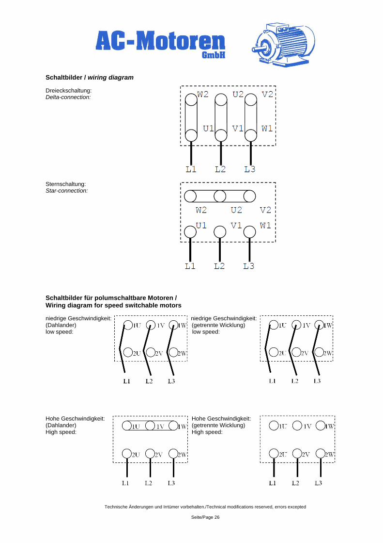
Technische Änderungen und Irrtümer vorbehalten./Technical modifications reserved, errors excepted
Seite/Page 26
Schaltbilder / wiring diagram
Dreieckschaltung: Delta-connection: Sternschaltung: Star-connection:
Schaltbilder für polumschaltbare Motoren / Wiring diagram for speed switchable motors
niedrige Geschwindigkeit: niedrige Geschwindigkeit: (Dahlander) (getrennte Wicklung) low speed: low speed: Hohe Geschwindigkeit: Hohe Geschwindigkeit: (Dahlander) (getrennte Wicklung) High speed: High speed:
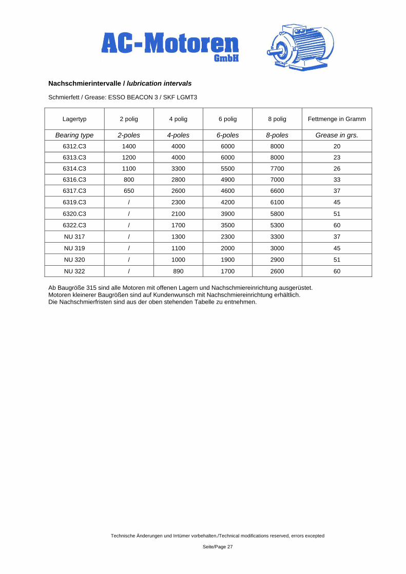
Technische Änderungen und Irrtümer vorbehalten./Technical modifications reserved, errors excepted
Seite/Page 27
Nachschmierintervalle / lubrication intervals
Schmierfett / Grease: ESSO BEACON 3 / SKF LGMT3
Lagertyp 2 polig 4 polig 6 polig 8 polig Fettmenge in Gramm
Bearing type 2-poles 4-poles 6-poles 8-poles Grease in grs.
6312.C3 1400 4000 6000 8000 20
6313.C3 1200 4000 6000 8000 23
6314.C3 1100 3300 5500 7700 26
6316.C3 800 2800 4900 7000 33
6317.C3 650 2600 4600 6600 37
6319.C3 / 2300 4200 6100 45
6320.C3 / 2100 3900 5800 51
6322.C3 / 1700 3500 5300 60
NU 317 / 1300 2300 3300 37
NU 319 / 1100 2000 3000 45
NU 320 / 1000 1900 2900 51
NU 322 / 890 1700 2600 60
Ab Baugröße 315 sind alle Motoren mit offenen Lagern und Nachschmiereinrichtung ausgerüstet. Motoren kleinerer Baugrößen sind auf Kundenwunsch mit Nachschmiereinrichtung erhältlich. Die Nachschmierfristen sind aus der oben stehenden Tabelle zu entnehmen.
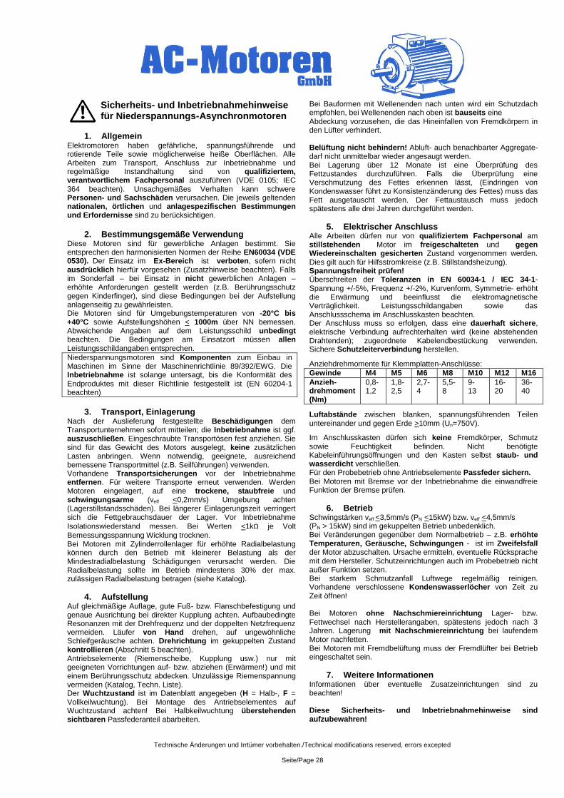
Technische Änderungen und Irrtümer vorbehalten./Technical modifications reserved, errors excepted
Seite/Page 28
Sicherheits- und Inbetriebnahmehinweise für Niederspannungs-Asynchronmotoren
1. Allgemein
Elektromotoren haben gefährliche, spannungsführende und rotierende Teile sowie möglicherweise heiße Oberflächen. Alle Arbeiten zum Transport, Anschluss zur Inbetriebnahme und regelmäßige Instandhaltung sind von qualifiziertem, verantwortlichem Fachpersonal auszuführen (VDE 0105; IEC 364 beachten). Unsachgemäßes Verhalten kann schwere Personen- und Sachschäden verursachen. Die jeweils geltenden nationalen, örtlichen und anlagespezifischen Bestimmungen und Erfordernisse sind zu berücksichtigen.
2. Bestimmungsgemäße Verwendung
Diese Motoren sind für gewerbliche Anlagen bestimmt. Sie entsprechen den harmonisierten Normen der Reihe EN60034 (VDE 0530). Der Einsatz im Ex-Bereich ist verboten, sofern nicht ausdrücklich hierfür vorgesehen (Zusatzhinweise beachten). Falls im Sonderfall – bei Einsatz in nicht gewerblichen Anlagen – erhöhte Anforderungen gestellt werden (z.B. Berührungsschutz gegen Kinderfinger), sind diese Bedingungen bei der Aufstellung anlagenseitig zu gewährleisten. Die Motoren sind für Umgebungstemperaturen von -20°C bis +40°C sowie Aufstellungshöhen < 1000m über NN bemessen. Abweichende Angaben auf dem Leistungsschild unbedingt beachten. Die Bedingungen am Einsatzort müssen allen Leistungsschildangaben entsprechen.
Niederspannungsmotoren sind Komponenten zum Einbau in Maschinen im Sinne der Maschinenrichtlinie 89/392/EWG. Die Inbetriebnahme ist solange untersagt, bis die Konformität des Endproduktes mit dieser Richtlinie festgestellt ist (EN 60204-1 beachten)
3. Transport, Einlagerung
Nach der Auslieferung festgestellte Beschädigungen dem Transportunternehmen sofort mitteilen; die Inbetriebnahme ist ggf. auszuschließen. Eingeschraubte Transportösen fest anziehen. Sie sind für das Gewicht des Motors ausgelegt, keine zusätzlichen Lasten anbringen. Wenn notwendig, geeignete, ausreichend bemessene Transportmittel (z.B. Seilführungen) verwenden. Vorhandene Transportsicherungen vor der Inbetriebnahme entfernen. Für weitere Transporte erneut verwenden. Werden Motoren eingelagert, auf eine trockene, staubfreie und schwingungsarme (veff <0,2mm/s) Umgebung achten (Lagerstillstandsschäden). Bei längerer Einlagerungszeit verringert sich die Fettgebrauchsdauer der Lager. Vor Inbetriebnahme
Isolationswiederstand messen. Bei Werten <1kΩ je Volt
Bemessungsspannung Wicklung trocknen. Bei Motoren mit Zylinderrollenlager für erhöhte Radialbelastung können durch den Betrieb mit kleinerer Belastung als der Mindestradialbelastung Schädigungen verursacht werden. Die Radialbelastung sollte im Betrieb mindestens 30% der max. zulässigen Radialbelastung betragen (siehe Katalog).
4. Aufstellung Auf gleichmäßige Auflage, gute Fuß- bzw. Flanschbefestigung und genaue Ausrichtung bei direkter Kupplung achten. Aufbaubedingte Resonanzen mit der Drehfrequenz und der doppelten Netzfrequenz vermeiden. Läufer von Hand drehen, auf ungewöhnliche Schleifgeräusche achten. Drehrichtung im gekuppelten Zustand kontrollieren (Abschnitt 5 beachten). Antriebselemente (Riemenscheibe, Kupplung usw.) nur mit geeigneten Vorrichtungen auf- bzw. abziehen (Erwärmen!) und mit einem Berührungsschutz abdecken. Unzulässige Riemenspannung vermeiden (Katalog, Techn. Liste). Der Wuchtzustand ist im Datenblatt angegeben (H = Halb-, F = Vollkeilwuchtung). Bei Montage des Antriebselementes auf Wuchtzustand achten! Bei Halbkeilwuchtung überstehenden sichtbaren Passfederanteil abarbeiten.
Bei Bauformen mit Wellenenden nach unten wird ein Schutzdach empfohlen, bei Wellenenden nach oben ist bauseits eine Abdeckung vorzusehen, die das Hineinfallen von Fremdkörpern in den Lüfter verhindert. Belüftung nicht behindern! Abluft- auch benachbarter Aggregate- darf nicht unmittelbar wieder angesaugt werden. Bei Lagerung über 12 Monate ist eine Überprüfung des Fettzustandes durchzuführen. Falls die Überprüfung eine Verschmutzung des Fettes erkennen lässt, (Eindringen von Kondenswasser führt zu Konsistenzänderung des Fettes) muss das Fett ausgetauscht werden. Der Fettaustausch muss jedoch spätestens alle drei Jahren durchgeführt werden.
5. Elektrischer Anschluss Alle Arbeiten dürfen nur von qualifiziertem Fachpersonal am stillstehenden Motor im freigeschalteten und gegen Wiedereinschalten gesicherten Zustand vorgenommen werden. Dies gilt auch für Hilfsstromkreise (z.B. Stillstandsheizung). Spannungsfreiheit prüfen! Überschreiten der Toleranzen in EN 60034-1 / IEC 34-1- Spannung +/-5%, Frequenz +/-2%, Kurvenform, Symmetrie- erhöht die Erwärmung und beeinflusst die elektromagnetische Verträglichkeit. Leistungsschildangaben sowie das Anschlussschema im Anschlusskasten beachten. Der Anschluss muss so erfolgen, dass eine dauerhaft sichere, elektrische Verbindung aufrechterhalten wird (keine abstehenden Drahtenden); zugeordnete Kabelendbestückung verwenden. Sichere Schutzleiterverbindung herstellen.
Anziehdrehmomente für Klemmplatten-Anschlüsse:
Gewinde M4 M5 M6 M8 M10 M12 M16
Anzieh-drehmoment (Nm)
0,8- 1,2
1,8- 2,5
2,7- 4
5,5- 8
9- 13
16- 20
36- 40
Luftabstände zwischen blanken, spannungsführenden Teilen untereinander und gegen Erde >10mm (Un=750V).
Im Anschlusskasten dürfen sich keine Fremdkörper, Schmutz sowie Feuchtigkeit befinden. Nicht benötigte Kabeleinführungsöffnungen und den Kasten selbst staub- und wasserdicht verschließen. Für den Probebetrieb ohne Antriebselemente Passfeder sichern. Bei Motoren mit Bremse vor der Inbetriebnahme die einwandfreie Funktion der Bremse prüfen.
6. Betrieb Schwingstärken veff <3,5mm/s (PN <15kW) bzw. veff <4,5mm/s (PN > 15kW) sind im gekuppelten Betrieb unbedenklich. Bei Veränderungen gegenüber dem Normalbetrieb – z.B. erhöhte Temperaturen, Geräusche, Schwingungen - ist im Zweifelsfall der Motor abzuschalten. Ursache ermitteln, eventuelle Rücksprache mit dem Hersteller. Schutzeinrichtungen auch im Probebetrieb nicht außer Funktion setzen. Bei starkem Schmutzanfall Luftwege regelmäßig reinigen. Vorhandene verschlossene Kondenswasserlöcher von Zeit zu Zeit öffnen! Bei Motoren ohne Nachschmiereinrichtung Lager- bzw. Fettwechsel nach Herstellerangaben, spätestens jedoch nach 3 Jahren. Lagerung mit Nachschmiereinrichtung bei laufendem Motor nachfetten. Bei Motoren mit Fremdbelüftung muss der Fremdlüfter bei Betrieb eingeschaltet sein.
7. Weitere Informationen Informationen über eventuelle Zusatzeinrichtungen sind zu beachten! Diese Sicherheits- und Inbetriebnahmehinweise sind aufzubewahren!
Technische Änderungen und Irrtümer vorbehalten./Technical modifications reserved, errors excepted
Seite/Page 29
AC 2013-1 08.10.13
Einstein Strasse 17, 64859 Eppertshausen Telefon: 06071-49887-0 Telefax: 06071-49887-20
e-mail: [email protected] www.ac-motoren.de