Embed Size (px)
Citation preview

Beschaffung und Logistik Sicatron bietet Ihnen alle Aspekte der Beschaffung und Bevorratung mit einer breiten Produktpalette elektromechanischer und elektronischer Komponenten sowie Subsysteme. Basierend auf unserer langjährigen Erfahrung, mit maximaler Leistung und persönlichem Engagement entwickeln wir für Sie wirtschaftliche und individuelle Lösungen. Sie haben alles aus einer Hand, ob Standardprodukt oder kundenspezifische Lösungen. Unser Partner:
Systemlösungen Sicatron plant und entwickelt mit Ihnen - vom Schalter bis zum kompletten Subsystem (Kabelkonfektion).
Fon +49 (0) 2331 473329-0 Fax +49 (0) 2331 473329 200 [email protected] www.sicatron.de
Schalttechnik l Steuerungstechnik l Systemlösungen l Kabelkonfektion l Beschaffung /Logistik
Beratung und Service
• Kompetente technische Beratung
• Exzellente Produktqualität,
• höchste Prozessdynamik,
• maximale Kundenorientierung
• Maßgeschneiderte Angebote ob kleine oder
große Mengen
• Persönliche Bestellannahme
• besten Service für den Ablauf Ihrer Bestellungen
Fon +49 (0) 2331-473329-0 Fax +49 (0) 2331-473329 200 [email protected]
ROHS konforme Produkte
elektronik & automation

Overview 2
Motors, Gearboxes and Electronics for Stepper Motors
Synchronous Motors 9
Rotational URT, UAT1, UAT3, UCM, UCR, UBR1, UBR2, UDR UDS, UO (SM5021/SM5022), UFM, UFR, UHM, UP (SM6443/SM6444)
49Rotational, Torque Limited UNU0 (SM3532RG), UOU0 (SM5032RG), UPU0 (SM6469RG)
58Linear UCC, UCK, UBK, UO Linear actuator (LA5021SM)
UO Spindle actuator (SP5021SM)
Stepper Motors 73
Rotational URG, UAG1, UAG3/4, UCD, UCB, UBD, UBB UDB, UO (ST5021/ST5022), UFD, UHD, UP (ST6443/ST6444)
117Linear UCE, UCL, UBL, UO Linear actuator (LA5021ST)
UO Spindle actuator (SP5022ST), Connector Types
Electronics for Stepper Motors 131
Driver Boards SAMOTRONIC101, SAMOTRONIC102, Evaluation-Kit 2
Gearboxes 135
VK2, UGA, UGD, VK4, UGM, UGB, UGF, UGV UGO/UGP (STG60/STG61), AP60, UGJ, UGR (STG200), UGS (V250)
Important notes to catalogue data 170
General technical terms and explanations 173
Table of Contents

www.saia-burgess.com Motor Products2 |
UDS UO UFM/UFR UHM UP
URT UAT1/UAT3 UCM/UCR UBR1/UBR2 UDR
64 x 43
most powerful packagewith STG/V gearboxes
12–230
250/375300/450
24/16
10,3–358,5–30
3,5–13,83,9–14,2
STG60/61/200; V250
44
28 x 24
standard modulescustomer specific interfaces
12–230
250/500300/600
24/12
0,8–1,30,8–1,3
0,31–0,580,38–0,69
on request
16/19
Type
Dimensions (mm)
Characteristics
Voltage (V)
Speed 50 Hz (rpm)60 Hz (rpm)
Pole number
Running torque (cNm)50 Hz60 Hz
Power output (W)50 Hz60 Hz
Gear combination
Page
Synchronous MotorsRotational
Motors
13 x 11
smallest motoroptional planetary gearbox with diameter 13mmpin connection or flex print
3–24
600720
10
0,060,06
0,0380,038
on request
9
20 x 17
long life precision bearing standard 24VAC motor
economic volumesolution
12–48/24
600720
10
0,31/0,360,3/0,34
0,19/0,220,23/026
on request
12/14
36 x 21
wide range of customised versions availableup to 230 VAC supply voltage
12–230
250/500300/600
24/12
0,75–0,90,72–0,9
0,24–0,390,28–0,45
A, D, M, B, F, V, J
22/24
48 x 24
compact reversiblesynchronous motor
12–230
500600
12
1,51,4
0,770,87
A, D, M, B, F, V, J
26
52 x 28 (56)
three-phase ACoperation possiblefor high power 2, 3or 4 coils
12–230
250/500300/600
24/12
2,8–5,32,6-4,7
1–2,81,1–3
A, D, M, B, F, V, J
35/37
59 x 35 (70)
powerful motorsynchronous version of the stepper motor UHD
12–230
250300
24
8,5–156,6–9,5
2,2–3,92,1–3
J
41
50 x 21
three speeds versionswide range of torque capacities
6–230
250/375/500300/450/600
24/16/12
2,0–7,51,8–7
0,65–2,750,78–3,0
VK4, STG60/61/200,V250
30
Type
Dimensions (mm)
Characteristics
Voltage (V)
Speed 50 Hz (rpm)60 Hz (rpm)
Pole number
Running torque (cNm)50 Hz60 Hz
Power output (W)50 Hz60 Hz
Gear combination
Page
Synchronous MotorsRotational
48 x 18,5
simple to connect, onlytwo wires
no capacitor uni-directional with anti-return mechanism
6–230
500600
12
0,90,8
0,50,5
A, D, M, B, F, V, J
28
(SM5021/SM5022) (SM6443/SM6444)
3

www.saia-burgess.comMotor Products | 3
UCC/UCK UBK UO UO Linear actuator Spindle actuator
UNU0 UOU0 UPU0
torque limiting feature abrasion-free, integrated low noise magnetic hysteresis clutch
50 x 32
24–230
375450
16
22
0,80,95
STG60/61/200,V250
52
64 x 69
24–230
375450
16
77
2,753,3
STG61/200,V250
55
35 x 32
24–230
375450
16
0,60,6
0,250,3
STG60/61/200,V250
49
Type
Dimensions (mm)
Characteristics
Voltage (V)
Speed 50 Hz (rpm)60 Hz (rpm)
Pole number
Torque Limited (cNm)50 Hz60 Hz
Power output (W)50 Hz60 Hz
Gear combination
Page
Synchronous MotorsRotational, Torque Limited
28 x 31
new linear motor using modules of the UC rangeintegrated non-rotational thread spindle
10/13
12–230
1,0
4,16/8,335/10
24/12
35
58/61
36 x 36
standard linear motor for extended travel the spindle has to be retained externally
8/13/56
12–230
1,0
6,67/8,338/10
12
35
64
Type
Dimensions (mm)
Characteristcs
Travel (mm)
Voltage (V)
Thread pitch (mm)
Speed (mm/s)50 Hz60 Hz
Pole number
Max Force (N)
Page
Synchronous Motors Linear
50 x 76
linear actuator with 3 speeds50 mm travelintegrated non-rotating threaded spindle
45–50
12–230
1,5/1,5/1,5
6,25/9,37/12,57,5/11,25/15
24/16/12
45–50
66
50 x 27
spindle typethreaded spindle has to be retained externally for extended travel
68–130
12–230
1,5/1,5/1,5
6,25/9,37/12,57,5/11,25/15
24/16/12
45–70/50–70
69
(SM3532RG) (SM5032RG) (SM6469RG
(LA5021SM) (SP5021/5022SM)
2

www.saia-burgess.com Motor Products4 |
UDB UO UFD/UFB UHD UP
URG UAG1 UAG3/4 UCD/UCB UBD/UBB
64 x 43
most powerful package with STG/V gearboxes
7,5/11,25
30–45
2–7
bipolar
STG60/61/200,V250
114
59 Tx 35 (70)
powerful standard motor7,5° stepper motor
7,5
13–45,5
1,3–5,3
bipolar/unipolar
J
109
52 x 28 (56)
two step angle motor
7,5/15
6,4–45,3
0,45–0,8
bipolar/unipolar
A, D, M, B, F, V, J
102/105
50 x 21
three step angle motor wide range of torque capabilities
7,5/11,25
3,7–4
0,25–1
bipolar
VK4, STG60/61/200V250
99
Stepper MotorsRotational
Type
Dimensions (mm)
Characteristics
Step angle(°)
Holding torque (cNm)
Detent torque (cNm)
Winding
Gear combination
Page
36 x 21
wide range of customised versions available
7,5/15
1,0–1,9
0,22–0,36
bipolar/unipolar
A, D, M, B, F, V
90/93
28 x 24
standard modulescustomer specific inter-faces
7,5/15
1,3–2,7
0,26–0,42
bipolar/unipolar
on request
82/86
20 x 17
precision bearingstandard motor
18
0,7/0,5
0,14
bipolar/unipolar
on request
76
13 x 11
high dynamicperformanceoptional planetary gear-box with motor diameterpin connection or flex print
18
0,20
0,03
bipolar
on request
73
Stepper MotorsRotational
Type
Dimensions (mm)
Characteristics
Step angle(°)
Holding torque (cNm)
Detent torque (cNm)
Winding
Gear combination
Page
(ST5021/ST5022) (ST6443/ST6444)
48 x 24
compact reversible 15° stepper motor
15
2,2–2,7
0,35
bipolar/unipolar
A, D, M, B, F, V, J
96
20 x 17
economic volumesolution
18
0,56/0,44
> 0,06
bipolar/unipolar
on request
79
5

www.saia-burgess.comMotor Products | 5
UCE/UCL UBL UO UO Linear actuator Spindle actuator
50 x 27
spindle typethreaded spindle has to be retained externally for extended travel
68–130
0,031/0,047/0,063
1,5/1,5/1,5
6,25/9,37/12,5
7,5/11,25/15
50–70
127
36 x 36
general purpose linear motorfor long travel version the spindle has to be retained externally
8/13/56
0,041
0,8
8,33
15
35
123
28 x 33
new linear motor using modules of the UC range integrated non-rotating threaded spindle
10/13
0,021/0,041
1,0
4,16/8,33
7,5/15
35
117/120
Stepper MotorsLinear
Type
Dimensions (mm)
Characteristics
Travel (mm)
Travel per step (mm)
Thread pitch (mm)
Speed (mm/s)at 200 Hz
Step angle (°)
Max. Force (N)
Page
50 x 76
linear actuator with 3step widths and 50 mmtravelintegrated non-rotating threaded spindle
45–50
0,031/0,047/0,063
1,5/1,5/1,5
6,25/9,37/12,5
7,5/11,25/15
45–50
125
(LA5021ST) (SP5022ST)
4

www.saia-burgess.com Motor Products6 |
SAMOTRONIC101 SAMOTRONIC102 Evaluation-Kit 2
55 x 40
small unipolar driverboard
for unipolar motors
10–24 DC
constant voltage drive
full/half step
internal or external
inhibit internal clockinhibit motor currentchange direction ofrotation
via DIP-switch, potentiometer
131
Type
Dimensions (mm)
Characteristics
Driver
Supply voltage (V)
Motor current
Step mode
Clock source
Control inputs to
Configuration
Page
Electronics for Stepper MotorsDriver Boards
metal case 164 x 130 x 45 (Euro-PCB)
tool for development, test and optimisation of stepper drive systemswindows-based softwarequick parameter setupvisualisation of speed and positionpositioning sequences capability
for unipolar and bipolar motors
3–48 DC24 AC
constant voltage drive andconstant current drive(chopper controlled)
full/half/micro step
internal, programmable
3 digital inputs4 signal outputs1 analog input 0…10 VDC 1 relay contact
RS 232, USB
133
84 x 54
small bipolar driver boardflash controleroptional customised software
for bipolar motors
standard version10–24 DCenhanced version10–42 DC
constant current drive(chopper controlled)adjustable via potentiometer
full/half step
internal or external
inhibit internal clockinhibit motor currentchange direction of rotation
via DIP-switchpotentiometer
132
7

www.saia-burgess.comMotor Products | 7
UGV UGO/UGP UGJ UGR UGS
1) max. value,for higher ratios
VK2 UGA/UGD VK4 UGM UGB/UGF
1) max. value, for higher ratios
70 x 100
high torque spur gears type
36
2500
62,5...1500
–
12 x 35
166
70 x 70
solid metal spur gears die-cast aluminium
housing
17
500
81/3...2.000
–
8 x 12
154
65/68 x 68
high performancehardened steel spur gearslow teeth profileoptional interface plates for DC motorsoption additional housing for IP 65
29,8–382)
600
61/4...5400
–
8 x 22
156
2) depends on ratio
65 x 107
the most extensive gearratio rangemedium torque two plate gear type with metal spur gears
28
1500
41/6...36 Mill.2500 with UGD
–
12 x 20
161
Type
Dimensions (mm)
Characteristics
Height
Max. torque (cNm)1)
Ratios
Internal slipping clutch
Standard shaft (mm)
Page
Gearboxes
70 x 130
high performance me-tal gear typerobust aluminium twin plate designcan be used with DC motors
38
2000
61/4...375
–
12 x 35
163
52
cylindrical 52 mm dia-meter design
20
40
611/4...1875
–
3 x 10
143
40
compactcylindrical shape
19
20
611/4...2250
–
3 x 10
135
55 x 62/65,6
established plastic gearswide range of ratios gears rotate on hardened steel shafts optional integrated slipping clutches
12/13
32
A: 41/6...360.000D: 41/6...6.048.000
optional
4 x 10
139/141
51 x 65.2
volume metal and plas-tic spur gearshardened steel shafts encluded in plastic hou-sing and metal plate
15
100
1211/2...4800
–
4 x 10
147
Type
Dimensions (mm)
Characteristics
Height
Max. torque (cNm)1)
Ratios
Internal slipping clutch
Standard shaft (mm)
Page
Gearboxes
58 x 81
robust metal spur gears,plastic primary gearsdie-cast aluminium housing
17
250/500
B: 412/3...345.600F: 41/6...5000
optional (UGB)
8 x 12
150/152
(STG60/STG61) (STG200) (V250)
6

Saia-Burgess is active in the development and manufacture of Switches, Motors, Solenoids, Control Components as well as related sub-systems.

www.saia-burgess.comMotor Products | 9
Synchronous Motor URT 1E N 24 V / 50 Hz R N
1E standard magnet5E stronger magnet
N
See next page
R reversible
N PinC flex print
This motor type doesn’t fulfil basis insulation requirements of EN 60335-1: 2004Customer application must realize a suitable protection class.
URT
Dimensions (mm)
Voltage (V)
Speed (rpm) 50 Hz
Pole number
Running torque *(mNm) 50 Hz/60 Hz
Power output (W)50 Hz/60 Hz
Gear combination
URTSynchronous Motors
Rotational
13 x 11
3–24
600
10
0,6
0,038
–
* standard magnet
Standard Data
Climatic class „wide-spread“ according to DIN IEC 60721-2-1Ambient temperature operation °C -15 ... +60Ambient temperature storage °C -20 ... +100Thermal resistance at f=0 Rtherm 83 K/WThermal class B according to DIN EN 60085Approval standardMounting any positionElectrical connection Pin, optional flex printProtection IP 40 according to DIN EN 60529Weight 7 g Rotor stalling motor can be stopped when voltage is applied, without being overheatedBearings integrated high temperature plastic bearing
Type
Configuration
Approvel
Voltage/Frequency
Direction
Connector
Order Reference
8
www.saia-burgess.com Motor Products10 |
URT
Technical Data
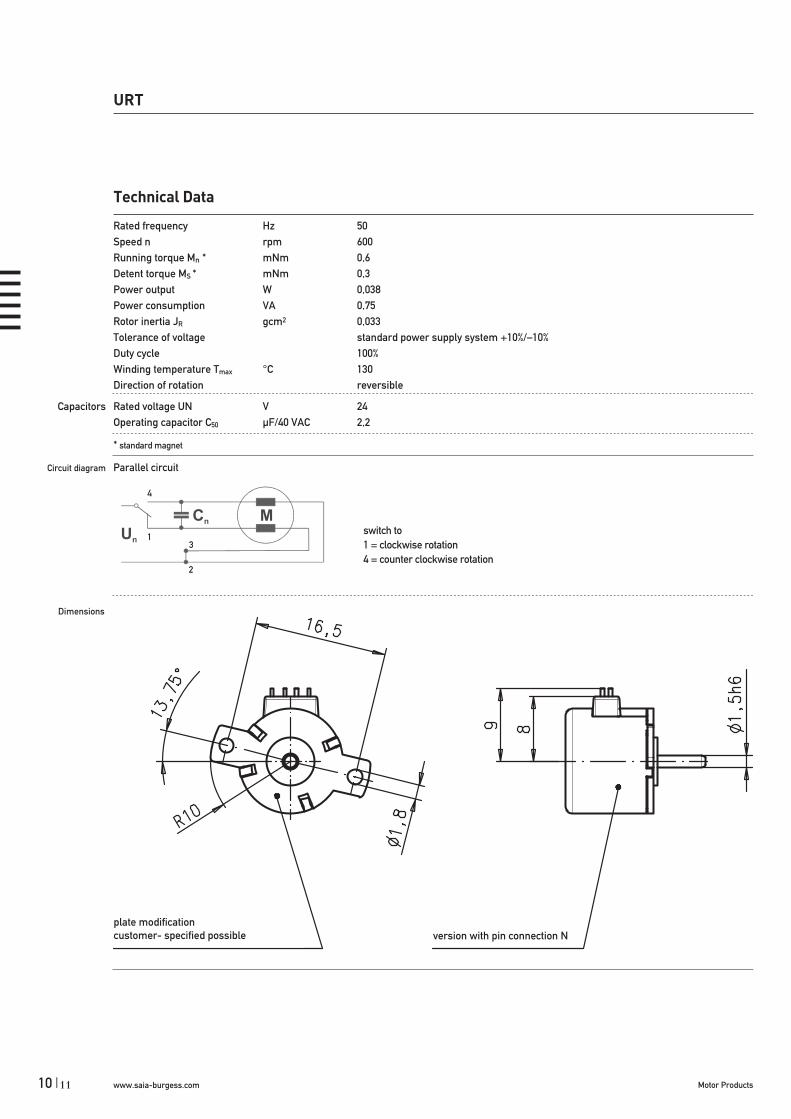
Rated frequency Hz 50Speed n rpm 600Running torque Mn * mNm 0,6Detent torque MS * mNm 0,3Power output W 0,038Power consumption VA 0,75Rotor inertia JR gcm2 0,033Tolerance of voltage standard power supply system +10%/–10%Duty cycle 100%Winding temperature Tmax °C 130Direction of rotation reversible
Capacitors Rated voltage UN V 24Operating capacitor C50 μF/40 VAC 2,2
* standard magnet
Circuit diagram Parallel circuit
Dimensions
switch to1 = clockwise rotation4 = counter clockwise rotation
4
13
2
plate modification customer- specified possible version with pin connection N
11

www.saia-burgess.comMotor Products | 11
URT
Dimensions
recommended FPC layout for flex print connector 1 mm
version with flex print circuit C
10

www.saia-burgess.com Motor Products12 |
UAT1
Dimensions (mm)
Voltage (V)
Speed (rpm) 50 Hz 60 Hz
Pole number
Running torque (cNm) 50 Hz
60 Hz
Power output (W) 50 Hz60 Hz
Gear combination
UAT1Synchronous Motors
Rotational
20 x 17,2
12–48
600720
10
0,310,3
0,190,23
on request
Standard Data
Climatic class „wide-spread“ according to DIN IEC 60721-2-1Ambient temperature operation °C -40 ... +60Ambient temperature storage °C -40 ... +100Thermal resistance at f=0 Rtherm 50 K/W Thermal class „B“ according to DIN EN 60085Approval standardMounting any positionElectrical connection insulation displacement connection, pins, lead wiresProtection IP 40 according to DIN EN 60529Weight 25 g Rotor stalling motor can be stopped when voltage is applied, without being overheatedBearings sintered bronze, self-lubricating
Type
Rotor shaft, mounting
Approval
Voltage/Frequency
Direction
Cable
Synchronous Motor UAT1 0 N 24 V/50 Hz R E
0 centring 8 mm, screw plate with thread M23 centring 8 mm, screw plate with slotted holeA centring 6 mm, screw plate with thread M2E centring 6 mm, screw plate with slotted hole
N Approval Standard
See next page
reversible
E Lead wires 150 mm with plug AMP MicroMatch 0-215083-6 (other on request)
Order Reference
13
www.saia-burgess.comMotor Products | 13
UAT1
Technical Data
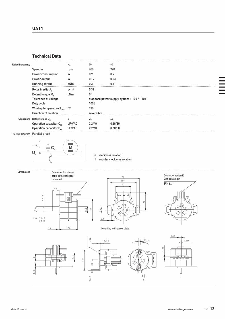
Rated frequency Hz 50 60
Speed n rpm 600 720
Power consumption W 0,9 0,9
Power output W 0,19 0,23
Running torque cNm 0,3 0,3
Rotor inertia JR gcm2 0,31
Detent torque MS cNm 0,1Tolerance of voltage standard power supply system + 10% / - 10%Duty cycle 100%
Winding temperature Tmax °C 130
Direction of rotation reversible
Capacitors Rated voltage UN V 24 48
Operation capacitor C50 μF/VAC 2,2/40 0,68/80Operation capacitor C60 μF/VAC 2,2/40 0,68/80
Circuit diagram
Dimensions
Parallel circuit
6 = clockwise rotation1 = counter clockwise rotation
Pin 6...1
Connector flat ribboncable to the left/rightor looped
Connector option Kwith contact pin
Mounting with screw plate
12

www.saia-burgess.com Motor Products14 |
Synchronous Motor UAT3 3 N 24 V/50 Hz R E
3 centring 8 mm, mounting plate with long holes5 centring 8 mm, mounting plate (for clipping)E centring 6 mm, mounting plate with long holesG centring 6 mm, mounting plate (for clipping)
N Approval Standard
See next page
reversible
E cable 150 mm with Tyco connector CT 173977-4 (other on request)
UAT3
Dimensions (mm)
Voltage (V)
Speed (rpm) 50 Hz60 Hz
Pole number
Running torque (cNm) 50 Hz
60 Hz
Power output (W) 50 Hz60 Hz
Gear combination
UAT3Synchronous Motors
Rotational
20 x 17,2
24
600720
10
0,360,34
0,220,26
on request
Standard Data
Climatic class „wide-spread“ according to DIN IEC 60721-2-1Ambient temperature operation °C -20 ... +60Ambient temperature storage °C -40 ... +100Thermal resistance at f=0 Rtherm 47 K/W Thermal class „B“ according to DIN EN 60085Approval standardMounting any positionElectrical connection lead wiresProtection IP 40 according to DIN EN 60529Weight 22 g Rotor stalling motor can be stopped when voltage is applied, without being overheatedBearings sintered bronze, self-lubricating
Type
Rotor shaft, mounting
Approval
Voltage/Frequency
Direction
Cable
Order Reference
15

www.saia-burgess.comMotor Products | 15
UAT3
Technical Data
Rated frequency Hz 50 60
Speed n rpm 600 720
Power consumption W 1,5 1,5
Power output W 0,22 0,26
Running torque cNm 0,36 0,34
Rotor inertia JR gcm2 0,26
Detent torque MS mNm > 0,6Tolerance of voltage standard power supply system + 10% / - 10%Duty cycle 100%
Winding temperature Tmax °C 130
Direction of rotation reversible
Capacitors Rated voltage UN V 24
Operation capacitor C50 μF/VAC 2,7/40
Circuit diagram Parallel circuit
Dimensions
switch to2 = clockwise rotation3 = counter clockwise rotation
motortype D
UAT33 8 h8UAT3E 6 h8
14

www.saia-burgess.com Motor Products16 |
Synchronous Motor UCM 1 0 N 24 V / 50 Hz R D
1 standard magnet5 stronger magnet
0 centring 8 mm, shaft 2,0 mm, screw plate A centring 10 mm, shaft 2,0 mm, screw plate1 centring 8 mm, shaft 1,5 mm, screw plate C centring 10 mm, shaft 1,5 mm, screw plate3 centring 8 mm, shaft 2,0 mm, clip E centring 10 mm, shaft 2,0 mm, clip4 centring 8 mm, shaft 1,5 mm, clip K centring 10 mm, shaft 1,5 mm, clip
N Approval Standard
See next page
R reversible
D see page 129 „Connection Types“N
UCM1/5
Dimensions (mm)
Voltage (V) *
Speed (rpm) 50 Hz
Pole number
Running torque ** (cNm) 50 Hz
60 Hz
Power output (W) **50 Hz60 Hz
Gear combination
UCMSynchronous Motors
Rotational
28 x 24
12–230
250
24
1,2–1,31,2–1,3
0,31–0,340,38–0,41
on request
* regard circuit diagram and connector type** values for lead wire version (connection N) / connector versions up to 15 % higher
Standard Data
Climatic class „wide-spread“ according to DIN IEC 60721-2-1Ambient temperature operation °C -15 ... +60Ambient temperature storage °C -20 ... +100Thermal resistance at f=0 Rtherm 29 K/WThermal class B according to DIN EN 60085Approval standardMounting any positionElectrical connection connector type D or NProtection IP 40 according to DIN EN 60529Weight 54 g Rotor stalling motor can be stopped when voltage is applied, without being overheatedBearings Sintered bronze, self- lubricating
Type
Configuration
Rotor shaft, mounting
Approvel
Voltage/Frequency
Direction
Connection
Order Reference
17

www.saia-burgess.comMotor Products | 17
UCM1/5
Technical Data
UCM 1 UCM 1 UCM 5 UCM 5
bipolar Rated frequency Hz 50 60 50 60Speed n rpm 250 300 250 300Running torque * cNm 1,2 1,2 1,3 1,3Detent torque MS cNm 0,18 0,18 0,36 0,36Power output * W 0,31 0,38 0,34 0,41Power consumption VA 2,2 2,2 2,2 2,2Rotor inertia JR gcm2 2,2 2,2 2,4 2,4Tolerance of voltage standard power supply system +10%/–10%Duty cycle 100%Winding temperature Tmax °C 130Direction of rotation reversible
Capacitors Rated voltage UN V 12 24 110Operating capacitor C50 μF/V~ 18/20 4,7/40 0,33/200
* values for lead wire version (connection N) / connector versions up to 15 % higher
Circuit diagram Parallel circuit 12 V, 24 V, 48 V, 110 V Parallel circuit 230 V (only for connector N) with 110 V motor and resistor RV
Parallel circuit 230 V (only for connector N) with 110 V motor and capacitor CV
Series resistor RV = 5,6 k , 3 W Series capacitor CV = 0,33 μF, 250 VAC
switch to
1 clockwise rotation
4 counter clockwise rotation
6 counter clockwise rotation(for series circuit)
16

www.saia-burgess.com Motor Products18 |
UCM1/5
Dimensions Version with Connector D
Version with Connector N
D 8 mm 10 mm
D 8 mm 10 mm
19

www.saia-burgess.comMotor Products | 19
Synchronous Motor UCR 1 0 N 24 V / 50 Hz R D
1 standard magnet5 stronger magnet
0 centring 8 mm, shaft 2,0 mm, screw plate A centring 10 mm, shaft 2,0 mm, screw plate1 centring 8 mm, shaft 1,5 mm, screw plate C centring 10 mm, shaft 1,5 mm, screw plate3 centring 8 mm, shaft 2,0 mm, clip E centring 10 mm, shaft 2,0 mm, clip4 centring 8 mm, shaft 1,5 mm, clip K centring 10 mm, shaft 1,5 mm, clip
N Approval Standard
See next page
R reversible
D see page 129 „Connection Types“N
UCR1/5
Dimensions (mm)
Voltage (V) *
Speed (rpm) 50 Hz
Pole number
Running torque **(cNm) 50 Hz
60 Hz
Power output (W) **50 Hz60 Hz
Gear combination
UCRSynchronous Motors
Rotational
28 x 24
12–230
500
12
0,8–1,10,8–1,1
0,42–0,580,50–0,69
on request
* regard circuit diagram and connector type** values for lead wire version (connection N) / connector versions up to 15 % higher
Standard Data
Climatic class wide-spread according to DIN IEC 60721-2-1Ambient temperature operation °C -15 ... +60Ambient temperature storage °C -20 ... +100Thermal resistance at f=0 Rtherm 29 K/WThermal class B according to DIN EN 60085Approval standardMounting any positionElectrical connection connector type D or NProtection IP 40 according to DIN EN 60529Weight 54 g Rotor stalling motor can be stopped when voltage is applied, without being overheatedBearings Sintered bronze, self- lubricating
Type
Configuration
Rotor shaft, mounting
Approvel
Voltage/Frequency
Direction
Connection
Order Reference
18

www.saia-burgess.com Motor Products20 |
UCR1/5
Technical Data
UCR 1 UCR 1 UCR 5 UCR 5
bipolar Rated frequency Hz 50 60 50 60Speed n rpm 500 600 500 600Running torque * cNm 0,8 0,8 1,1 1,1Detent torque MS cNm 0,18 0,18 0,4 0,4Power output * W 0,42 0,50 0,58 0,69Power consumption VA 2,2 2,2 2,2 2,2Rotor inertia JR gcm2 2,1 2,1 2,4 2,4Tolerance of voltage standard power supply system +10%/–10%Duty cycle 100%Winding temperature Tmax °C 130Direction of rotation reversible
Capacitors Rated voltage UN V 12 24 110Operating capacitor C50 μF/V~ 22/20 5,6/40 0,27/200
* values for lead wire version (connection N) / connector versions up to 15 % higher
Circuit diagram Parallel circuit 12 V, 24 V, 48 V, 110 V Parallel circuit 230 V (only for connector N) with 110 V motor and resistor RV
Parallel circuit 230 V (only for connector N) with 110 V motor and capacitor CV
Series resistor RV = 5,6 k , 3 W Series capacitor CV = 0,33 μF, 250 VAC
switch to
1 clockwise rotation
4 counter clockwise rotation
6 counter clockwise rotation(for series circuit)
21
www.saia-burgess.comMotor Products | 21
UCR1/5
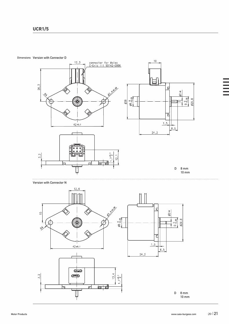
Dimensions Version with Connector D
Version with Connector N
D 8 mm 10 mm
D 8 mm 10 mm
20

www.saia-burgess.com Motor Products22 |
UBR1
Dimensions (mm)
Voltage (V)
Speed (rpm) 50 Hz60 Hz
Pole number
Running torque (cNm) 50 Hz
60 Hz
Power output (W) 50 Hz60 Hz
Gear combination
UBR1Synchronous Motors
Rotational
36 x 21
12–230
250300
24
0,90,9
0,240,28
A, D, M, B, F, V, J
Type
Rotor shaft, mounting
Approval
Voltage/Frequency
Direction
Cable
Synchronous Motor UBR1 0 N 24 V/50 Hz R E
0 centring 8 mm, shaft 2,0 mm, clip A centring 10 mm, shaft 2,0 mm, clip1 centring 8 mm, shaft 1,5 mm, clip C centring 10 mm, shaft 1,5 mm, clip3 centring 8 mm, shaft 2,0 mm, screw plate E centring 10 mm, shaft 2,0 mm, screw plate4 centring 8 mm, shaft 1,5 mm, screw plate K centring 10 mm, shaft 1,5 mm, screw plate
N Approval Standard
See next page
reversible
E cable 150 mm (other on request)
Standard Data
Climatic class wide-spread according to DIN IEC 60721-2-1Ambient temperature operation °C -15...+55Ambient temperature storage °C -20...+100Thermal resistance at f=0 Rtherm 27 K/WThermal class A according to DIN EN 60085Approval standard (UL/CSA on request)Mounting any positionElectrical connection cableProtection IP 40 according to DIN EN 60529Weight 60 g Rotor stalling motor can be stopped when voltage is applied, without being overheatedBearings sintered bronze, self-lubricatingElectric strength according to DIN EN 60034-1/DIN EN 60335-1
Order Reference
23

www.saia-burgess.comMotor Products | 23
UBR1
Technical Data
Rated frequency Hz 50 60
Speed n rpm 250 300
Power consumption W 1,3 1,3
Power output W 0,24 0,28
Running torque cNm 0,9 0,9
Rotor inertia JR gcm2 2,8
Detent torque MS cNm 0,22Tolerance of voltage standard power supply system + 10% / - 10%Duty cycle 100%
Winding temperature Tmax °C 105
Direction of rotation reversible
Capacitors Rated voltage UN V 12 24 48 110 230
Operation capacitor C50 μF/VAC 12/20 3,3/40 0,82/200 0,15/200 0,22/200
Operation capacitor C60 μF/VAC 12/20 3,3/40 0,82/200 0,15/200 0,12/200
Circuit diagram
Dimensions
Parallel circuit 12V, 24V, 48V, 110V Parallel circuit 230V
Parallel circuit 230V
Red = clockwise rotationBlack = counter clockwise rotation
Series circuit 230V
22

www.saia-burgess.com Motor Products24 |
Type
Rotor shaft, mounting
Approval
Voltage/Frequency
Direction
Cable
Synchronous Motor UBR2 0 N 24 V/50 Hz R E
0 centring 8 mm, shaft 2,0 mm, clip A centring 10 mm, shaft 2,0 mm, clip1 centring 8 mm, shaft 1,5 mm, clip C centring 10 mm, shaft 1,5 mm, clip3 centring 8 mm, shaft 2,0 mm, screw plate E centring 10 mm, shaft 2,0 mm, screw plate4 centring 8 mm, shaft 1,5 mm, screw plate K centring 10 mm, shaft 1,5 mm, screw plate
N Approval Standard
See next page
reversible
E cable 150 mm (other on request)
Order Reference
UBR2Synchronous Motors
Rotational
UBR2
Dimensions (mm)
Voltage (V)
Speed (rpm) 50 Hz60 Hz
Pole number
Running torque (cNm) 50 Hz
60 Hz
Power output (W) 50 Hz60 Hz
Gear combination
36 x 21
12–230
500600
12
0,750,72
0,390,45
A, D, M, B, F, V, J
Standard Data
Climatic class wide-spread according to DIN IEC 60721-2-1Ambient temperature operation °C -15...+55Ambient temperature storage °C -20...+100Thermal resistance at f=0 Rtherm 27 K/WThermal class A according to DIN EN 60085Approval standard (UL/CSA on request)Mounting any positionElectrical connection cableProtection IP 40 according to DIN EN 60529Weight 60 g Rotor stalling motor can be stopped when voltage is applied, without being overheatedBearings sintered bronze, self-lubricatingElectric strength according to DIN EN 60034-1/DIN EN 60335-1
25

www.saia-burgess.comMotor Products | 25
UBR2
Technical Data
Rated frequency Hz 50 60
Speed n rpm 500 600
Power consumption W 1,6 1,6
Power output W 0,39 0,45
Running torque cNm 0,75 0,72
Rotor inertia JR gcm2 2,8Detent torque MS cNm 0,25Tolerance of voltage standard power supply system + 10% / - 10%Duty cycle 100%
Winding temperature Tmax °C 105
Direction of rotation reversible
Capacitors Rated voltage UN V 12 24 48 110 230
Operation capacitor C50 μF/VAC 15/20 3,9/40 1,0/70 0,18/170 0,27/170
Operation capacitor C60 μF/VAC 15/20 3,9/40 1,0/70 0,18/170 0,22/170
Circuit diagram
Dimensions
Parallel circuit 12V, 24V, 48V, 110V Parallel circuit 230V
Parallel circuit 230V
Red = clockwise rotationBlack = counter clockwise rotation
Series circuit 230V
24

www.saia-burgess.com Motor Products26 |
UDRSynchronous Motors
Rotational
UDR1
Dimensions (mm)
Voltage (V)
Speed (rpm) 50 Hz60 Hz
Pole number
Running torque (cNm) 50 Hz
60 Hz
Power output (W) 50 Hz60 Hz
Gear combination
48 x 24
12–230
500600
12
1,51,4
0,770,87
A, D, M, B, F, V, J
Standard Data
Climatic class wide-spread according to DIN IEC 60721-2-1Ambient temperature operation °C -15...+60Ambient temperature storage °C -20...+100Thermal resistance at f=0 Rtherm 18 K/WThermal class A according to DIN EN 60085Approval standard/UL/CSAMounting any positionElectrical connection cableProtection IP 40 according to DIN EN 60529Weight 132 g Rotor stalling motor can be stopped when voltage is applied, without being overheatedBearings sintered bronze, self-lubricatingElectric strength according to DIN EN 60034-1/DIN EN 60335-1
Type
Rotor shaft, mounting
Approval
Voltage/Frequency
Direction
Cable
Synchronous Motor UDR1 0 N 24 V/50 Hz R N
0 centring 8 mm, shaft 1,5 mm, clip1 centring 8 mm, shaft 2,0 mm, clip
N Approval StandardU Approval UL/CSA
See next page
reversible
N cable 150 mm (other on request)
Order Reference
27

www.saia-burgess.comMotor Products | 27
Technical Data
Rated frequency Hz 50 60
Speed n rpm 500 600
Power consumption W 2,1 2,2
Power output W 0,77 0,87
Running torque cNm 1,5 1,4
Rotor inertia JR gcm2 6,3
Detent torque MS cNm 0,35Tolerance of voltage standard power supply system + 10% / - 10%Duty cycle 100 %
Winding temperature Tmax °C 105
Direction of rotation reversible
Capacitors Rated voltage UN V 12 24 48 110 230
Operation capacitor C50 μF/VAC 27/20 6,8/40 1,5/100 0,27/200 0,068/350
Operation capacitor C60 μF/VAC 22/20 4,7/40 1,5/100 0,27/200 0,068/350
Circuit diagram
Dimensions
UDR1
Parallel circuit
Red = clockwise rotationBlack = counter clockwise rotation
+0,03
5+0
,013
+0,007- 0,007
0-0,006
26
www.saia-burgess.com Motor Products28 |
UDSSynchronous Motors
Rotational (Uni-directional with anti-return mechanism)
UDS1
Dimensions (mm)
Voltage (V)
Speed (rpm) 50 Hz60 Hz
Pole number
Running torque (cNm) 50 Hz
60 Hz
Power output (W) 50 Hz60 Hz
Gear combination
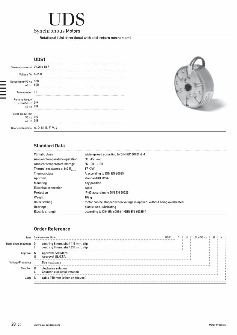
48 x 18,5
6–230
500600
12
0,90,8
0,50,5
A, D, M, B, F, V, J
Standard Data
Climatic class wide-spread according to DIN IEC 60721-2-1Ambient temperature operation °C -15...+60Ambient temperature storage °C -20...+100Thermal resistance at f=0 Rtherm 17 K/WThermal class A according to DIN EN 60085Approval standard/UL/CSAMounting any positionElectrical connection cableProtection IP 40 according to DIN EN 60529Weight 102 g Rotor stalling motor can be stopped when voltage is applied, without being overheatedBearings plastic, self-lubricatingElectric strength according to DIN EN 60034-1/DIN EN 60335-1
Type
Rotor shaft, mounting
Approval
Voltage/Frequency
Direction
Cable
Synchronous Motor UDS1 0 N 24 V/50 Hz R N
0 centring 8 mm, shaft 1,5 mm, clip1 centring 8 mm, shaft 2,0 mm, clip
N Approval StandardU Approval UL/CSA
See next page
R clockwise rotationL Counter-clockwise rotation
N cable 150 mm (other on request)
Order Reference
29

www.saia-burgess.comMotor Products | 29
UDS1
Technical Data
Rated frequency Hz 50 60
Speed n rpm 500 600
Power consumption W 2,4 1,8
Power output W 0,5 0,5
Running torque cNm 0,9 0,8
Rated voltage UN V 6, 12, 24, 48, 110, 230
Rotor inertia JR gcm2 11
Detent torque MS cNm 0,27 (in direction of rotation)Tolerance of voltage standard power supply system + 10% / - 10%Duty cycle 100 %
Winding temperature Tmax °C 105
Direction of rotation clockwise or counter-clockwise
Dimensions
Clockwise counter clockwise
0-0,014
0-0,006
+0,0
35+0
,013
28

www.saia-burgess.com Motor Products30 |
Synchronous Motor SM5021 R / SM5022 R 250 24 V 50 Hz
250375500
24 V110 V230 V
50 Hz60 Hz50/60 Hz
UO (SM5021; SM5022)
Dimensions (mm)
Voltage (V)
Speed (rpm) 50 Hz60 Hz
Pole number
Running torque (cNm) 50 Hz
60 Hz
Power output (W)50 Hz60 Hz
Gear combination
UOSynchronous Motors
Rotational
50 x 21
6–230
250/375/500300/450/600
24/16/12
2,0–3,3 (SM5021); 3,3–7,5 (SM5022)1,8–3 (SM5021); 4,5–7,0 (SM5022)
0,65–2,75 (SM5021); 1,3–2,73 (SM5022)0,78–3,0 (SM5021); 1,8–2,83 (SM5022)
VK4, UGO/UGP (STG60/61), UGR (STG200), UGS (V250)
Standard Data
Climatic class wide-spread according to DIN IEC 60721-2-1Ambient temperature operation °C -15 ... +40Ambient temperature storage °C -20 ... +100Thermal class B (SM5021) ; A (SM5022) according to DIN EN 60085Approval standardMounting any positionElectrical connection cableProtection IP 40 according to DIN EN 60529Weight 170 ... 180 g (SM5021); 180 ... 195 g (SM5022)Rotor stalling motor can be stopped when voltage is applied, without being overheatedBearings Sintered bronze, self- lubricating
Type
rpm
Voltage
Frequency
Order Reference
SM5021 SM5022
31

www.saia-burgess.comMotor Products | 31
UO (SM5021; SM5022)
Technical Data
Motor type (SM5021) R-250/1 R250/1 R-500/1 R-500/1 R-375/1 R-375/1 R-375/2 R-375/2Rated frequency Hz 50 60 50 60 50 60 50 60Speed of rotation rpm 250 300 500 600 375 450 375 450Running torque Mn cNm 2,5 2,5 2 1,8 2,3 2 3,3 3Power output W 0,65 0,78 1 1,1 0,9 0,95 1,3 1,4Power consumption VA 3,86 4,37 4,37 4,83 4,2 4,6 6 6,7Nominal current at 230 V mA 16,8 19 19 21 18,3 20 26 29Max. permissible ext. inertia gcm2 30 10 10 10 15 10 10 10Detent torque Ms cNm 0,25 0,25 0,25 0,25 0,25 0,25 0,25 0,25Winding temperature increase K 55 60 63 70 60 65 80 85Weight g 180 180 170 170 180 180 180 180
Capacitors at UN: 24 V μF/V~ 10/63 10/63 10/63 10/63 10/63 10/63 15/63 15/63at UN: 110 V μF/V~ 0,47/250 0,47/250 0,47/250 0,47/250 0,47/250 0,47/250 0,75/250 0,75/250at UN: 230 V μF/V~ 0,12/500 0,12/500 0,12/500 0,12/500 0,12/500 0,12/500 0,18/500 0,18/500
Motor type (SM5022) R-250/1 R-250/1 R-250/S2 R-250/S2 R-375/1 R-375/1 R-375/S2 R-375/S2Rated frequency Hz 50 60 50 60 50 60 50 60Speed of rotation rpm 250 300 250 300 375 450 375 450Running torque Mn cNm 6 5,7 7,5 7 4,7 4,5 7 6,5Power output W 1,57 1,8 2 2,2 1,85 2,1 2,7 3Power consumption VA 6,1 6,6 9 9,7 6,45 6,9 9,2 10,4Nominal current at 230 V mA 26,5 28,7 39,1 42,2 28 30 40 45Max. permissible ext. inertia gcm2 50 20 60 30 60 40 20 40Detent torque Ms cNm 1 1 1 1 1 1 1 1Winding temperature increase K 85 90 60 (S2 10 min.) 85 90 60 (S2 10 min.)Weight g 195 195 195 195 195 195 195 195
Capacitors at UN: 24 V μF/V~ 15/63 15/63 25/63 25/63 15/63 15/63 25/63 25/63at UN: 110 V μF/V~ 0,75/250 0,75/250 1,2/250 1,2/250 0,75/250 0,75/250 1,2/250 1,2/250at UN: 230 V μF/V~ 0,18/500 0,18/500 0,27/500 0,27/500 0,18/500 0,18/500 0,27/500 0,27/500
Motor type R-500 R-500 R-500/S2 R-500/S2Rated frequency Hz 50 60 50 60Speed of rotation rpm 500 600 500 600Running torque Mn cNm 3,7 3,2 5,2 4,5Power output W 1,94 2 2,73 2,83Power consumption VA 6,21 6,67 8,85 9,2Nominal current at 230 V mA 27 29 38,5 40Max. permissible ext. inertia gcm2 35 15 45 25Detent torque Ms cNm 1 1 1 1Winding temperature increase K 85 90 55 (S2 10 min.)Weight g 195 195 195 195
Capacitors at UN: 24 V μF/V~ 15/63 15/63 25/63 25/63at UN: 110 V μF/V~ 0,75/250 0,75/250 1,2/250 1,2/250at UN: 230 V μF/V~ 0,18/500 0,18/500 0,27/500 0,27/500
30

www.saia-burgess.com Motor Products32 |
Circuit diagram Parallel circuit
Dimensions
24-230 V ~
black wire green wire
Switch position drawn with acontinuous line results in clockwise rotation as viewed whenlooking at the motor shaft.
grey
Standard - wire length: 200 mm / 4 mm strippedGeneral tolerances acc. to DIN ISO 2768-mk
UO (SM5021; SM5022)
33

www.saia-burgess.comMotor Products | 33
Chart: Torque versus voltage
UOM1 (SM 5021 R-250/1) UOR1 (SM 5021 R-500/1)
cNm cNm
Supply voltage / Nominal voltage Supply voltage / Nominal voltage
UOU1 (SM 5021 R-375/1) UOU1 (SM 5021 R-375/2)
cNm cNm
Supply voltage / Nominal voltage Supply voltage / Nominal voltage
UO (SM5021; SM5022)
32
www.saia-burgess.com Motor Products34 |
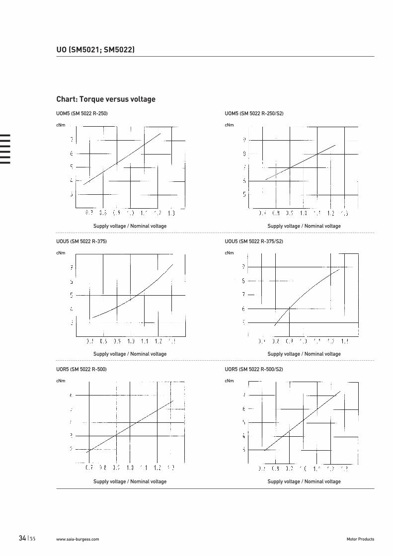
UO (SM5021; SM5022)
Chart: Torque versus voltage
UOM5 (SM 5022 R-250) UOM5 (SM 5022 R-250/S2)
cNm cNm
Supply voltage / Nominal voltage Supply voltage / Nominal voltage
UOU5 (SM 5022 R-375) UOU5 (SM 5022 R-375/S2)
cNm cNm
Supply voltage / Nominal voltage Supply voltage / Nominal voltage
UOR5 (SM 5022 R-500) UOR5 (SM 5022 R-500/S2)
cNm cNm
Supply voltage / Nominal voltage Supply voltage / Nominal voltage
35
www.saia-burgess.comMotor Products | 35
Type
Rotor shaft, mounting
Approval
Voltage/Frequency
Direction
Cable
Synchronous Motor UFM1 0 N 24 V/50 Hz R N
0 centring 8 mm, shaft 3,0 mm, clip E centring 10 mm, shaft 3,0 mm, screw plate1 centring 8 mm, shaft 2,0 mm, clip K centring 10 mm, shaft 2,0 mm, screw plate2 centring 8 mm, shaft 1,5 mm, clip M centring 10 mm, shaft 1,5 mm, screw plate3 centring 8 mm, shaft 3,0 mm, screw plate4 centring 8 mm, shaft 2,0 mm, screw plate5 centring 8 mm, shaft 1,5 mm, screw plate
N Approval Standard
See next page
reversible
N cable 150 mm (other on request)
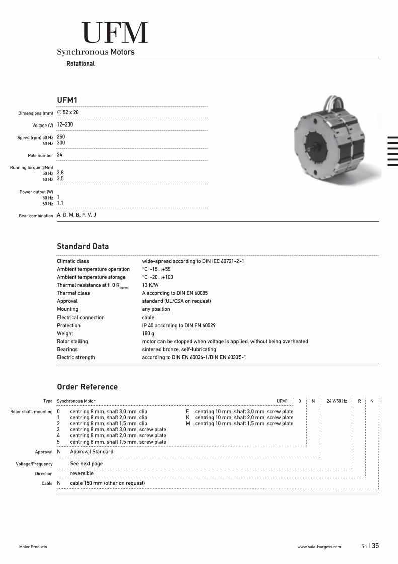
UFMSynchronous Motors
Rotational
UFM1
Dimensions (mm)
Voltage (V)
Speed (rpm) 50 Hz60 Hz
Pole number
Running torque (cNm)50 Hz 60 Hz
Power output (W) 50 Hz60 Hz
Gear combination
52 x 28
12–230
250300
24
3,83,5
11,1
A, D, M, B, F, V, J
Standard Data
Climatic class wide-spread according to DIN IEC 60721-2-1Ambient temperature operation °C -15...+55Ambient temperature storage °C -20...+100Thermal resistance at f=0 Rtherm 13 K/WThermal class A according to DIN EN 60085Approval standard (UL/CSA on request)Mounting any positionElectrical connection cableProtection IP 40 according to DIN EN 60529Weight 180 gRotor stalling motor can be stopped when voltage is applied, without being overheatedBearings sintered bronze, self-lubricatingElectric strength according to DIN EN 60034-1/DIN EN 60335-1
Order Reference
34

www.saia-burgess.com Motor Products36 |
Technical Data
Rated frequency Hz 50 60
Speed n rpm 250 300
Power consumption W 4 3,1
Power output W 1 1,1
Running torque cNm 3,8 3,5
Rotor inertia JR gcm2 14,4Detent torque MS cNm 0,45Tolerance of voltage standard power supply system + 10% / - 10%Duty cycle 100%
Winding temperature Tmax °C 105
Direction of rotation reversible
Capacitors Rated voltage UN V 12 24 48 110 230
Operation capacitor C50 μF/VAC 39/24 10/45 2,2/90 0,39/240 0,1/440
Operation capacitor C60 μF/VAC 33/24 8,2/45 1,8/90 0,33/240 0,082/440
Circuit diagram
Dimensions
UFM1
3 -3h6
Parallel circuit
Red = clockwise rotationBlack = counter clockwise rotation
37

www.saia-burgess.comMotor Products | 37
Synchronous Motor UFR 1 0 N 24 V/50 Hz R N
1 Two coils3 Three coils4 Four coils
0 centring 8 mm, shaft 3,0 mm, clip E centring 10 mm, shaft 3,0 mm, screw plate*1 centring 8 mm, shaft 2,0 mm, clip K centring 10 mm, shaft 2,0 mm, screw plate*2 centring 8 mm, shaft 1,5 mm, clip M centring 10 mm, shaft 1,5 mm, screw plate*3 centring 8 mm, shaft 3,0 mm, screw plate*4 centring 8 mm, shaft 2,0 mm, screw plate*5 centring 8 mm, shaft 1,5 mm, screw plate*
N Approval Standard
See next page
reversible
N cable 150 mm (other on request)
* screw plate not for UFR3 and UFR4
Type
Configuration
Rotor shaft, mounting
Approval
Voltage/Frequency
Direction
Cable
UFRSynchronous Motors
Rotational
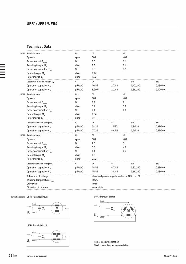
UFR1/UFR3/UFR4
Dimensions (mm)
Voltage (V)
Speed (rpm) 50 Hz60 Hz
Pole number
Running torque (cNm)50 Hz 60 Hz
Power output (W) 50 Hz60 Hz
Gear combination
52 x 28 / 52 x 42 / 52 x 56
12–230
500600
12
2,8 / 3,7 / 5,32,6 / 3,1 / 4,7
1,5 / 1,9 / 2,81,6 / 2 / 3
A, D, M, B, F, V, J
Standard Data
Climatic class wide-spread according to DIN IEC 60721-2-1Ambient temperature operation °C -15...+55Ambient temperature storage °C -20...+100Thermal resistance at f=0 Rtherm 11 K/W (UFR1), 7 K/W (UFR4)Thermal class A according to DIN EN 60085Approval standard (UL/CSA on request)Mounting any positionElectrical connection cableProtection IP 40 according to DIN EN 60529Weight 180 g (UFR1), 370 g (UFR4)Rotor stalling motor can be stopped when voltage is applied, without being overheatedBearings sintered bronze, self-lubricatingElectric strength according to DIN EN 60034-1/DIN EN 60335-1
Order Reference
36
www.saia-burgess.com Motor Products38 |
Technical Data
UFR1 Rated frequency Hz 50 60
Speed n rpm 500 600
Power output Pmech W 1,5 1,6
Running torque Mn cNm 2,8 2,6Power consumption Pel W 3,3 3,6
Detent torque MS cNm 0,46Rotor inertia JR gcm2 14,2
Capacitors at Rated voltage UN V 24 48 110 230
Operation capacitor C50 μF/VAC 10/45 2,7/90 0,47/200 0,12/400
Operation capacitor C60 μF/VAC 8,2/45 2,2/90 0,39/200 0,10/400
UFR3 Rated frequency Hz 50 60
Speed n rpm 500 600
Power output Pmech W 1,9 2
Running torque Mn cNm 3,7 3,1Power consumption Pel W 6,1 5,1
Detent torque MS cNm 0,54Rotor inertia JR gcm2 17
Capacitors at Rated voltage UN V 24 48 110 230
Operation capacitor C50 μF/VAC 39/24 10/50 1,8/110 0,39/240
Operation capacitor C60 μF/VAC 27/24 6,8/50 1,2/110 0,27/240
UFR4 Rated frequency Hz 50 60
Speed n rpm 500 600
Power output Pmech W 2,8 3
Running torque Mn cNm 5,3 4,7Power consumption Pel W 6,4 6,9
Detent torque MS cNm 0,8Rotor inertia JR gcm2 24,2
Capacitors at Rated voltage UN V 24 48 110 230
Operation capacitor C50 μF/VAC 18/45 4,7/90 0,82/200 0,22/440
Operation capacitor C60 μF/VAC 15/45 3,9/90 0,68/200 0,18/440
Tolerance of voltage standard power supply system + 10% ... - 10%Winding temperature Tmax 105°CDuty cycle 100%Direction of rotation reversible
Circuit diagram
UFR1/UFR3/UFR4
UFR1 Parallel circuit
UFR4 Parallel circuit
UFR3 Parallel circuit
Red = clockwise rotationBlack = counter clockwise rotation
39

www.saia-burgess.comMotor Products | 39
UFR1/UFR3/UFR4
Dimensions
UFR1
UFR3
3 -3h6
-
38

Dimensions
UFR4
-
UFR1/UFR3/UFR4
41 www.saia-burgess.com Motor Products40 |
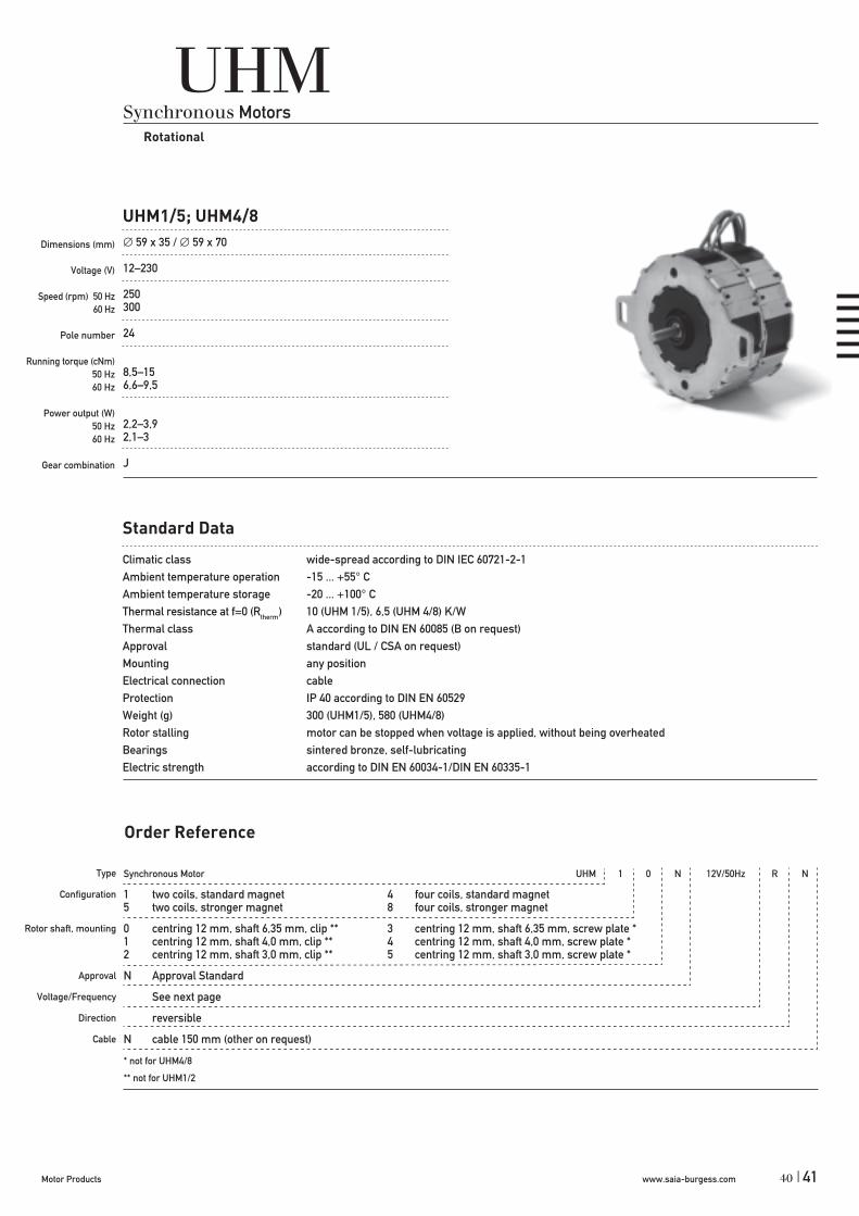
UHMSynchronous Motors
Rotational
UHM1/5; UHM4/8
Dimensions (mm)
Voltage (V)
Speed (rpm) 50 Hz60 Hz
Pole number
Running torque (cNm)50 Hz 60 Hz
Power output (W) 50 Hz60 Hz
Gear combination
59 x 35 / 59 x 70
12–230
250300
24
8,5–156,6–9,5
2,2–3,92,1–3
J
Standard Data
Climatic class wide-spread according to DIN IEC 60721-2-1Ambient temperature operation -15 ... +55° CAmbient temperature storage -20 ... +100° CThermal resistance at f=0 (Rtherm) 10 (UHM 1/5), 6,5 (UHM 4/8) K/WThermal class A according to DIN EN 60085 (B on request)Approval standard (UL / CSA on request)Mounting any positionElectrical connection cableProtection IP 40 according to DIN EN 60529Weight (g) 300 (UHM1/5), 580 (UHM4/8)Rotor stalling motor can be stopped when voltage is applied, without being overheatedBearings sintered bronze, self-lubricatingElectric strength according to DIN EN 60034-1/DIN EN 60335-1
Type
Configuration
Rotor shaft, mounting
Approval
Voltage/Frequency
Direction
Cable
Order Reference
Synchronous Motor UHM 1 0 N 12V/50Hz R N
1 two coils, standard magnet 4 four coils, standard magnet5 two coils, stronger magnet 8 four coils, stronger magnet
0 centring 12 mm, shaft 6,35 mm, clip ** 3 centring 12 mm, shaft 6,35 mm, screw plate *1 centring 12 mm, shaft 4,0 mm, clip ** 4 centring 12 mm, shaft 4,0 mm, screw plate *2 centring 12 mm, shaft 3,0 mm, clip ** 5 centring 12 mm, shaft 3,0 mm, screw plate *
N Approval Standard
See next page
reversible
N cable 150 mm (other on request)
* not for UHM4/8
** not for UHM1/2
40www.saia-burgess.comMotor Products | 41
www.saia-burgess.com Motor Products42 |
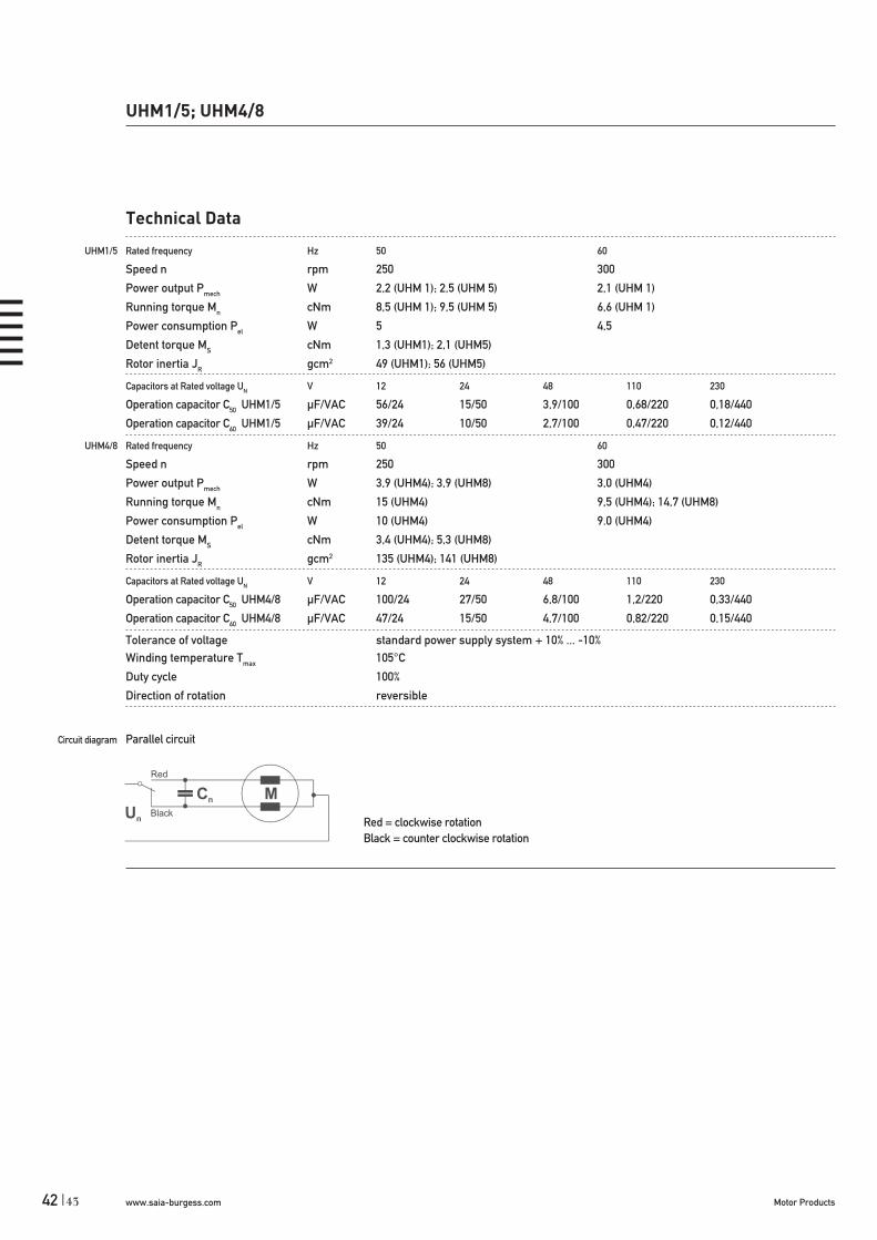
UHM1/5; UHM4/8
Technical Data
UHM1/5 Rated frequency Hz 50 60
Speed n rpm 250 300
Power output Pmech W 2,2 (UHM 1); 2,5 (UHM 5) 2,1 (UHM 1)
Running torque Mn cNm 8,5 (UHM 1); 9,5 (UHM 5) 6,6 (UHM 1)
Power consumption Pel W 5 4,5
Detent torque MS cNm 1,3 (UHM1); 2,1 (UHM5)
Rotor inertia JR gcm2 49 (UHM1); 56 (UHM5)
Capacitors at Rated voltage UN V 12 24 48 110 230
Operation capacitor C50 UHM1/5 μF/VAC 56/24 15/50 3,9/100 0,68/220 0,18/440
Operation capacitor C60 UHM1/5 μF/VAC 39/24 10/50 2,7/100 0,47/220 0,12/440
UHM4/8 Rated frequency Hz 50 60
Speed n rpm 250 300
Power output Pmech W 3,9 (UHM4); 3,9 (UHM8) 3,0 (UHM4)
Running torque Mn cNm 15 (UHM4) 9,5 (UHM4); 14,7 (UHM8)
Power consumption Pel W 10 (UHM4) 9.0 (UHM4)
Detent torque MS cNm 3,4 (UHM4); 5,3 (UHM8)
Rotor inertia JR gcm2 135 (UHM4); 141 (UHM8)
Capacitors at Rated voltage UN V 12 24 48 110 230
Operation capacitor C50 UHM4/8 μF/VAC 100/24 27/50 6,8/100 1,2/220 0,33/440
Operation capacitor C60 UHM4/8 μF/VAC 47/24 15/50 4,7/100 0,82/220 0,15/440
Tolerance of voltage standard power supply system + 10% ... -10%Winding temperature Tmax 105°C
Duty cycle 100%
Direction of rotation reversible
Circuit diagram Parallel circuit
Red = clockwise rotationBlack = counter clockwise rotation
43

www.saia-burgess.comMotor Products | 43
Dimensions
UHM1/5
UHM4/8
UHM1/5; UHM4/8
D Rotorshaft
6.35 h64.00 h83,00 g8
42
www.saia-burgess.com Motor Products44 |
Synchronous Motor SM6443 R / SM6444 250 24 V 50 Hz
250 (SM6443 R)375 (SM6443 R / SM6444 R)
24 V110 V230 V
50 Hz60 Hz50/60 Hz
Order Reference
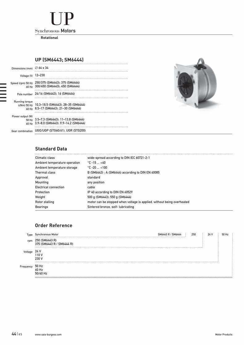
UPSynchronous Motors
Rotational
UP (SM6443; SM6444)
Dimensions (mm)
Voltage (V)
Speed (rpm) 50 Hz60 Hz
Pole number
Running torque (cNm) 50 Hz
60 Hz
Power output (W)50 Hz60 Hz
Gear combination
64 x 34
12–230
250/375 (SM6443); 375 (SM6444)300/450 (SM6443); 450 (SM6444)
24/16 (SM6443); 16 (SM6444)
10,3–18,5 (SM6443); 28–35 (SM6444)8,5–17 (SM6443); 21–30 (SM6444)
3,5–7,3 (SM6443); 11–13,8 (SM6444)3,9–8,0 (SM6443); 9,9–14,2 (SM6444)
UGO/UGP (STG60/61), UGR (STG200)
Standard Data
Climatic class wide-spread according to DIN IEC 60721-2-1Ambient temperature operation °C -15 ... +40Ambient temperature storage °C -20 ... +100Thermal class B (SM6443) ; A (SM6444) according to DIN EN 60085Approval standardMounting any positionElectrical connection cableProtection IP 40 according to DIN EN 60529Weight 500 g (SM6443); 550 g (SM6444)Rotor stalling motor can be stopped when voltage is applied, without being overheatedBearings Sintered bronze, self- lubricating
Type
rpm
Voltage
Frequency
45
www.saia-burgess.comMotor Products | 45
Mn
Ms
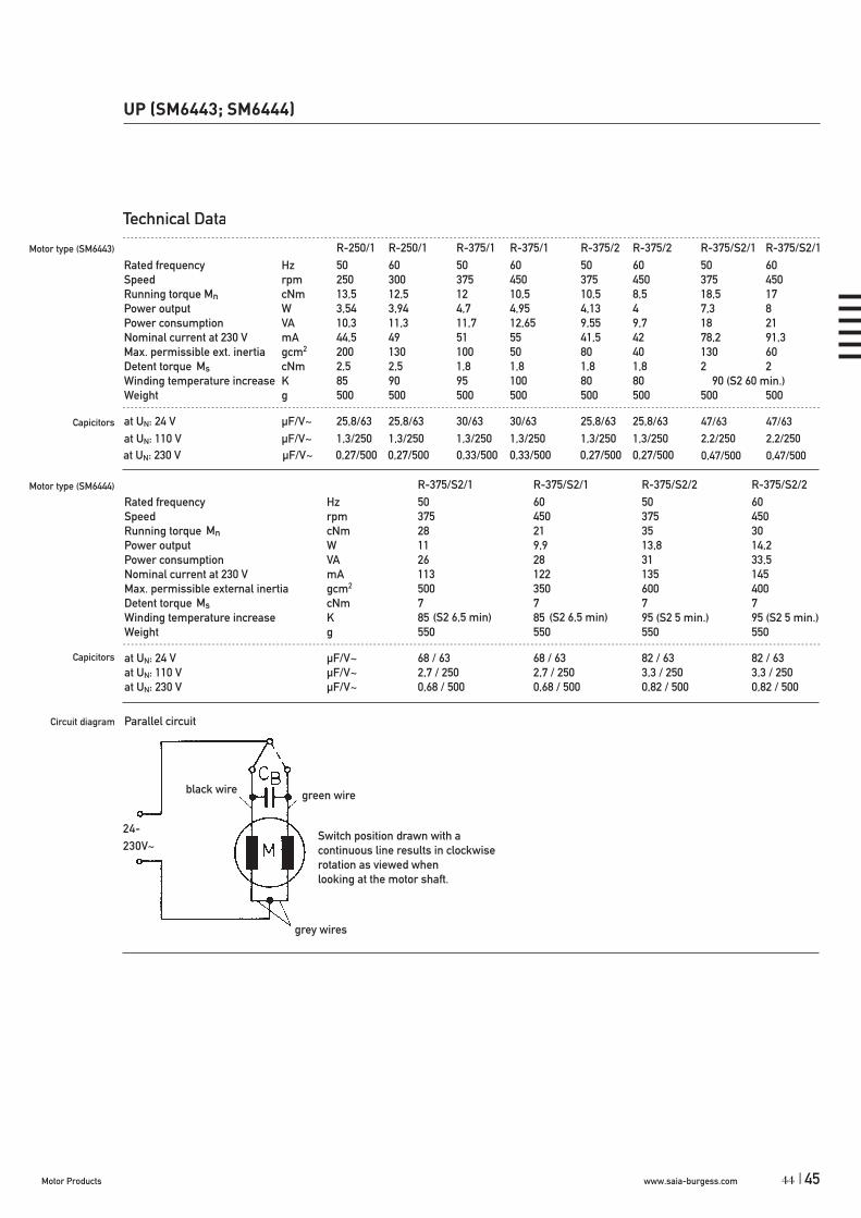
at UN: 230 V μF/V~ 0,27/500 0,27/500 0,33/500 0,33/500 0,27/500 0,27/500 0,33/500 0,33/500
UP (SM6443; SM6444)
47/63 47/632,2/250 2,2/2500,47/500 0,47/500
Motor type (SM6443)
Capicitors
Motor type (SM6444)
Capicitors
Mn
Ms
44
(S2 6,5 min) (S2 6,5 min)

www.saia-burgess.com Motor Products46 |
UP (SM6443; SM6444)
47
*
* on request 14h9
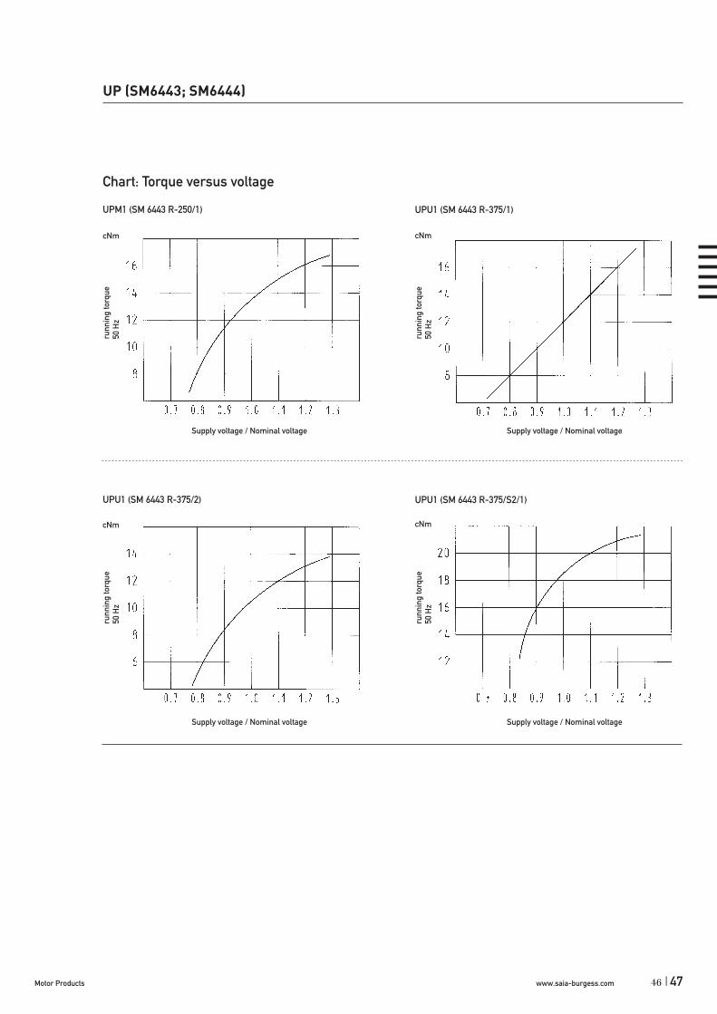
www.saia-burgess.comMotor Products | 47
UPM1 (SM 6443 R-250/1) UPU1 (SM 6443 R-375/1)
UPU1 (SM 6443 R-375/2) UPU1 (SM 6443 R-375/S2/1)
UP (SM6443; SM6444)
46

www.saia-burgess.com Motor Products48 |
UP (SM6443; SM6444)
UPU5 (SM 6444 R-375/S2/1) UPU5 (SM 6444 R-375/S2/2)
UPU5 (SM 6444 R-375/S2/1) UPU5 (SM 6444 R-375/S2/2)
49

www.saia-burgess.comMotor Products | 49
Synchronous Motor SM 3532 RG 375 24 V 50 Hz
24 V110 V230 V
50 Hz60 Hz
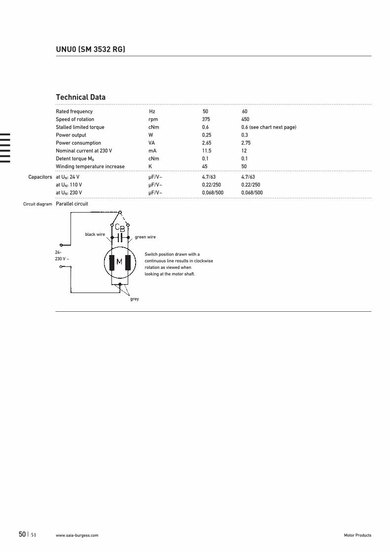
UNU0 (SM 3532 RG)
Dimensions (mm)
Voltage (V)
Speed (rpm) 50 Hz60 Hz
Pole number
Stalled limited torque (cNm)
50 Hz60 Hz
Power output (W)50 Hz60 Hz
Gear combination
UNU0Synchronous Motors
Torque Limited, with abrasion-free, integrated low noise magnetic hysteresis clutch
35 x 32
24–230
375450
16
0,60,6
0,250,3
UGO/UGP (STG60/61), UGR (STG200), UGS (V250)
Standard Data
Climatic class wide-spread according to DIN IEC 60721-2-1Ambient temperature operation °C -15 ... +40Ambient temperature storage °C -20 ... +100Thermal class B according to DIN EN 60085Approval standardMounting any positionElectrical connection cableProtection IP 40 according to DIN EN 60529Weight 100 g Rotor stalling motor can be stopped when voltage is applied, without being overheatedBearings Sintered bronze, self- lubricating
Type
Voltage
Frequency
Order Reference
48
www.saia-burgess.com Motor Products50 |
UNU0 (SM 3532 RG)
Technical Data
Rated frequency Hz 50 60Speed of rotation rpm 375 450Stalled limited torque cNm 0,6 0,6 (see chart next page)Power output W 0,25 0,3Power consumption VA 2,65 2,75Nominal current at 230 V mA 11,5 12Detent torque Ms cNm 0,1 0,1Winding temperature increase K 45 50
Capacitors at UN: 24 V μF/V~ 4,7/63 4,7/63at UN: 110 V μF/V~ 0,22/250 0,22/250at UN: 230 V μF/V~ 0,068/500 0,068/500
Circuit diagram Parallel circuit
24-230 V ~
black wire green wire
Switch position drawn with acontinuous line results in clockwise rotation as viewed whenlooking at the motor shaft.
grey
51

www.saia-burgess.comMotor Products | 51
Chart: Torque limit versus motor temperature
UNU0 (SM 3532 RG-375)
cNm
°C
Motor temperature
UNU0 (SM 3532 RG)
Dimensions
Standard - wire length: 100 mm / 6 mm strippedGeneral tolerances acc. to DIN ISO 2768-mk
Torq
ue li
mit
50 H
z
50

www.saia-burgess.com Motor Products52 |
UOU0 (SM 5032 RG)
Dimensions (mm)
Voltage (V)
Speed (rpm) 50 Hz60 Hz
Pole number
Stalled limited torque (cNm)
50 Hz60 Hz
Power output (W)50 Hz60 Hz
Gear combination
UOU0Synchronous Motors
Torque Limited, with abrasion-free, integrated low noise magnetic hysteresis clutch
50 x 32
24–230
375450
16
22
0,80,95
UGO/UGP (STG60/61), UGR (STG200), UGS (V250)
Standard Data
Climatic class wide-spread according to DIN IEC 60721-2-1Ambient temperature operation °C -15 ... +40Ambient temperature storage °C -20 ... +100Thermal class B according to DIN EN 60085Approval standardMounting any positionElectrical connection cableProtection IP 40 according to DIN EN 60529Weight 190 g Rotor stalling motor can be stopped when voltage is applied, without being overheatedBearings Sintered bronze, self- lubricating
Type
Voltage
Frequency
Order Reference
Synchronous Motor SM 5032 RG 375 24 V 50 Hz
24 V110 V230 V
50 Hz60 Hz
53

www.saia-burgess.comMotor Products | 53
UOU0 (SM 5032 RG)
Technical Data
Rated frequency Hz 50 60Speed of rotation rpm 375 450Stalled limited torque cNm 2 2 (see chart next page)Power output W 0,8 0,95Power consumption VA 4,1 5,3Nominal current at 230 V mA 18 23Detent torque Ms cNm 0,3 0,3Winding temperature increase K 55 70
Capacitors at UN: 24 V μF/V~ 10/63 10/63at UN: 110 V μF/V~ 0,47/250 0,47/250at UN: 230 V μF/V~ 0,12/500 0,12/500
Circuit diagram Parallel circuit
24-230 V ~
black wire green wire
Switch position drawn with acontinuous line results in clockwise rotation as viewed whenlooking at the motor shaft.
grey
52

www.saia-burgess.com Motor Products54 |
Chart: Torque limit versus motor temperature
UOU0 (SM 5032 RG-375)
cNm
°C
Motor temperature
UOU0 (SM 5032 RG)
Dimensions
Standard - wire length: 200 mm / 4 mm strippedGeneral tolerances acc. to DIN ISO 2768-mk
Torq
ue li
mit
50 H
z
55
www.saia-burgess.comMotor Products | 55
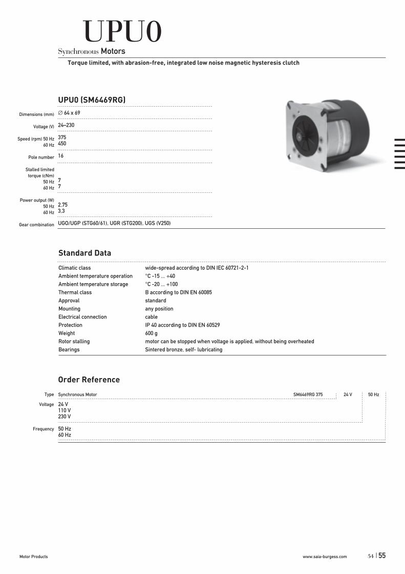
UPU0Synchronous Motors
Torque limited, with abrasion-free, integrated low noise magnetic hysteresis clutch
UPU0 (SM6469RG)
Dimensions (mm)
Voltage (V)
Speed (rpm) 50 Hz60 Hz
Pole number
Stalled limited torque (cNm)
50 Hz60 Hz
Power output (W)50 Hz60 Hz
Gear combination
64 x 69
24–230
375450
16
77
2,753,3
UGO/UGP (STG60/61), UGR (STG200), UGS (V250)
Standard Data
Climatic class wide-spread according to DIN IEC 60721-2-1Ambient temperature operation °C -15 ... +40Ambient temperature storage °C -20 ... +100Thermal class B according to DIN EN 60085Approval standardMounting any positionElectrical connection cableProtection IP 40 according to DIN EN 60529Weight 600 g Rotor stalling motor can be stopped when voltage is applied, without being overheatedBearings Sintered bronze, self- lubricating
Type
Voltage
Frequency
Order Reference
Synchronous Motor SM6469RG 375 24 V 50 Hz
24 V110 V230 V
50 Hz60 Hz
54

www.saia-burgess.com Motor Products56 |
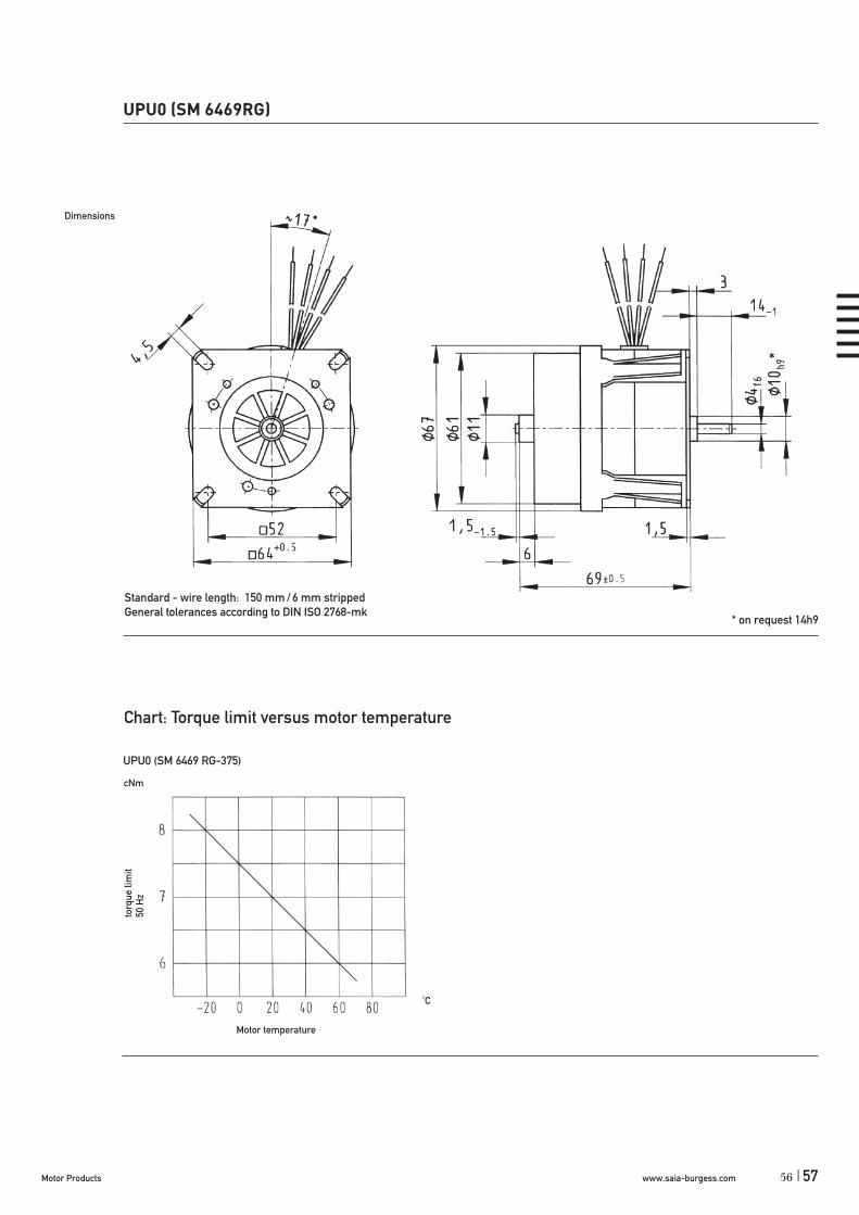
UPU0 (SM 6469RG)
Technical Data
Rated frequency Hz 50 60Speed of rotation rpm 375 450Stalled limited torque cNm 7 7 (see chart next page)Power output W 2,75 3,3Power consumption VA 10,5 13,5Nominal current at 230 V mA 46 59Detent torque Ms cNm 3 3Winding temperature increase K 70 90
Capacitors at UN: 24 V μF/V~ 30/63 30/63at UN: 110 V μF/V~ 1,3/250 1,3/250at UN: 230 V μF/V~ 0,33/500 0,33/500
Circuit diagram Parallel circuit
24-230 V ~
black wire green wire
Switch position drawn with acontinuous line results in clockwise rotation as viewed whenlooking at the motor shaft.
grey
57
www.saia-burgess.comMotor Products | 57
Dimensions
UPU0 (SM 6469RG)
UPU0 (SM 6469 RG-375)
56
*
* on request 14h9

www.saia-burgess.com Motor Products58 |
Synchronous Motor UCC 13 N 24 V / 50 Hz B 1A
13 standard magnet 53 stronger magnet
N
see next page
C see page 129 „Connection Types“DN
1A Travel 10 mm ± 0,7 mm1B Travel 13 mm ± 0,7 mm
UCC1/5
Dimensions (mm)
Travel (mm)
Voltage (V) **
Thread pitch (mm)
Speed (mm/s)50 Hz60 Hz
Pole number
Max. Force (N)*
UCCSynchronous Motors
Linear
28 x 31
10/13
12–230
1,0
4,165
24
35
* Depends on winding, frequency and lifetime required. Values for connector versions (C, D) / lead wire versions (N) up to 20 % lower.Drive against end stops only permissible after clarification of operating conditions and approval by Saia-Burgess.
** regard circuit diagram and connector type
Standard Data
Climatic class wide-spread according to DIN IEC 60721-2-1Ambient temperature operation °C -15 ... +60Ambient temperature storage °C -20 ... +100Thermal resistance at f=0 Rtherm 29 K/WThermal class B according to DIN EN 60085Winding coil temperature increase K 60Approval standardMounting any positionElectrical connection connector type C, D, NProtection IP 40 according to DIN EN 60529Weight 67 g Rotor stalling motor can be stopped when voltage is applied, without being overheated
Type
Configuration
Approval
Voltage/frequency
Connection
Shaft
Order Reference
59
www.saia-burgess.comMotor Products | 59
UCC1/5
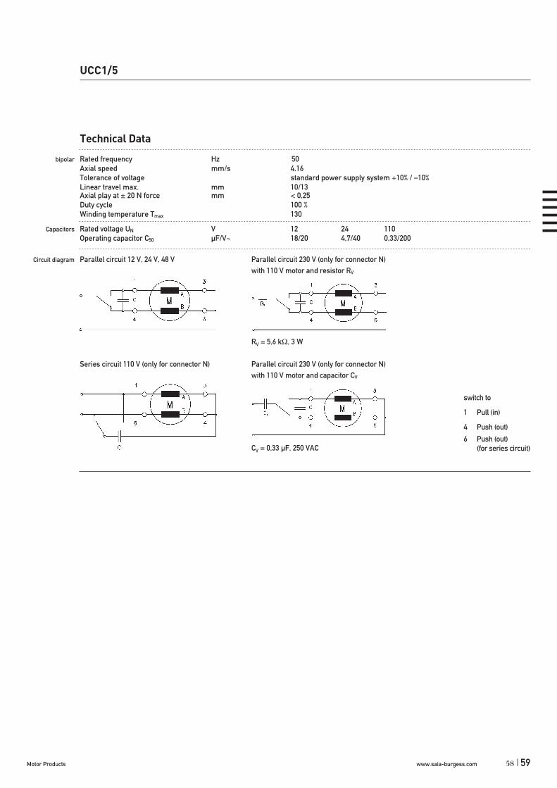
Technical Data
bipolar Rated frequency Hz 50Axial speed mm/s 4,16Tolerance of voltage standard power supply system +10% / –10% Linear travel max. mm 10/13Axial play at ± 20 N force mm < 0,25Duty cycle 100 %Winding temperature Tmax 130
Capacitors Rated voltage UN V 12 24 110Operating capacitor C50 μF/V~ 18/20 4,7/40 0,33/200
Circuit diagram Parallel circuit 12 V, 24 V, 48 V Parallel circuit 230 V (only for connector N) with 110 V motor and resistor RV
RV = 5,6 k , 3 W
Series circuit 110 V (only for connector N) Parallel circuit 230 V (only for connector N) with 110 V motor and capacitor CV
CV = 0,33 μF, 250 VAC
switch to
1 Pull (in)
4 Push (out)
6 Push (out)(for series circuit)
58

www.saia-burgess.com Motor Products60 |
Dimensions
UCC1/5
Version with Connector D, with 10 mm travel
Trave l
61
www.saia-burgess.comMotor Products | 61
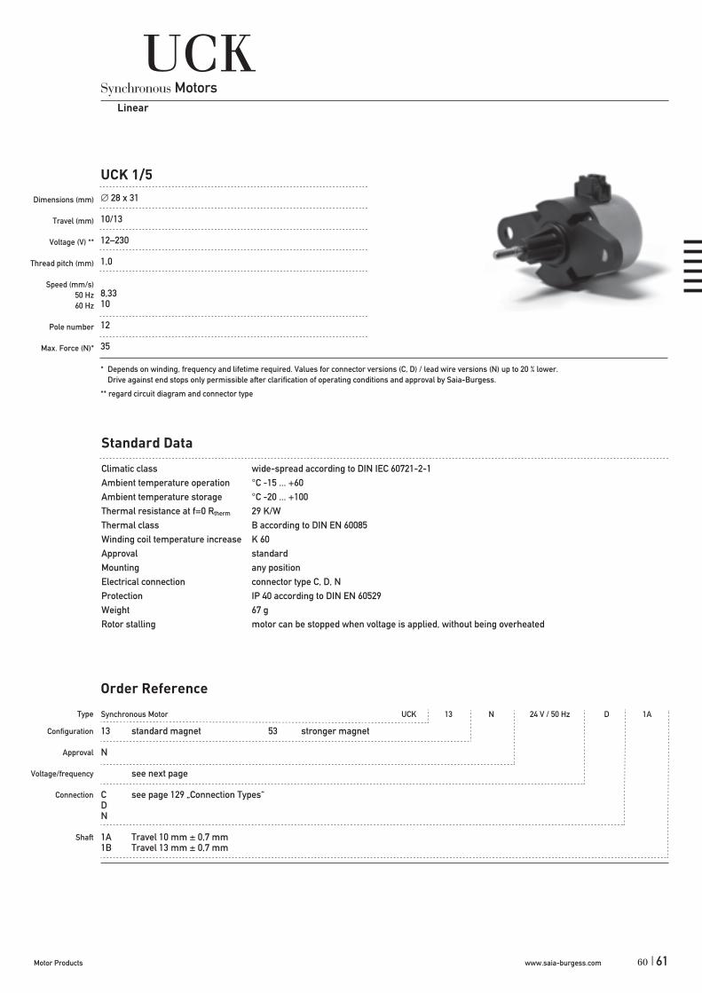
Synchronous Motor UCK 13 N 24 V / 50 Hz D 1A
13 standard magnet 53 stronger magnet
N
see next page
C see page 129 „Connection Types“DN
1A Travel 10 mm ± 0,7 mm1B Travel 13 mm ± 0,7 mm
UCK 1/5
Dimensions (mm)
Travel (mm)
Voltage (V) **
Thread pitch (mm)
Speed (mm/s)50 Hz60 Hz
Pole number
Max. Force (N)*
UCKSynchronous Motors
Linear
28 x 31
10/13
12–230
1,0
8,3310
12
35
* Depends on winding, frequency and lifetime required. Values for connector versions (C, D) / lead wire versions (N) up to 20 % lower.Drive against end stops only permissible after clarification of operating conditions and approval by Saia-Burgess.
** regard circuit diagram and connector type
Standard Data
Climatic class wide-spread according to DIN IEC 60721-2-1Ambient temperature operation °C -15 ... +60Ambient temperature storage °C -20 ... +100Thermal resistance at f=0 Rtherm 29 K/WThermal class B according to DIN EN 60085Winding coil temperature increase K 60Approval standardMounting any positionElectrical connection connector type C, D, NProtection IP 40 according to DIN EN 60529Weight 67 g Rotor stalling motor can be stopped when voltage is applied, without being overheated
Type
Configuration
Approval
Voltage/frequency
Connection
Shaft
Order Reference
60

www.saia-burgess.com Motor Products62 |
UCK 1/5
Technical Data
Rated frequency Hz 50Speed mm/s 8,33Tolerance of voltage standard power supply system +10% / –10% Linear travel max. mm 10/13Axial play at 20 N force mm < 0,25Duty cycle 100 %Winding temperature Tmax 130
Capacitors Rated voltage UN V 12 24 110Operating capacitor C50 μF/V~ 22/20 5,6/40 0,47/170
Circuit diagram Parallel circuit 12 V, 24 V, 48 V Parallel circuit 230 V (only for connector N) with 110 V motor and resistor RV
RV = 5,6 k , 3 W
Series circuit 110 V (only for connector N) Parallel circuit 230 V (only for connector N) with 110 V motor and capacitor CV
CV = 0,33 μF, 250 VAC
switch to
1 Pull (in)
4 Push (out)
6 Push (out)(for series circuit)
63

www.saia-burgess.comMotor Products | 63
Version with Connector D, with 10 mm travel
Trave l
UCK 1/5
Dimensions
62

www.saia-burgess.com Motor Products64 |
UBKSynchronous Motors
Linear
UBK1
Dimensions (mm)
Travel (mm)
Voltage (V)
Thread pitch (mm)
Speed (mm/s)50 Hz60 Hz
Pole number
Max. Force (N)*
Lifetime
36 x 36
8/13/56 ± 0,7
12–230
1,0
6,67/8,338/10
12
35
on request
*Depends on winding, frequency and lifetime required. Drive against end stops only permissible after clarification of operating conditions and approval by Saia-Burgess.
Standard Data
Climatic class wide-spread according to DIN IEC 60721-2-1Ambient temperature operation °C -15...+60Ambient temperature storage °C -20...+100Thermal resistance at f=0 Rtherm 27 K/WThermal class B according to DIN EN 60085Approval StandardMounting any positionElectrical connection jack connectorProtection IP 40 according to DIN EN 60529Weight 90 gRotor stalling motor can be stopped when voltage is applied without being overheated, with controlled duty cycleBearings ball bearing, for live time lubricatedElectric strength according to DIN EN 60034-1/DIN EN 60335-1
Type
Approval
Voltage/Frequency
Connector
Shaft
Synchronous Motor UBK1 N 12V/50Hz B 3C
N Approval Standard
See next page
6 pole connector (other on request)
3C Travel 8 mm ± 0,7 mm (other on request)
Order Reference
65

www.saia-burgess.comMotor Products | 65
UBK1
Technical Data
Rated frequency Hz 50 60
Axial speed mm/sec 8,33 10
Tolerance of voltage standard power supply system + 10% / - 10%Linear travel max. mm 8; 13; 56 ± 0,7
Axial play at ± 20 N force mm < 0,25
Duty cycle 100%
Winding temperature Tmax °C 130
Capacitors Rated voltage UN V 24 48
Operation capacitor C50 μF/VAC 3,9/40 1,0/70
Operation capacitor C60 μF/VAC 3,9/40 1,0/70
Dimensions
1 connector B AMP 829 836-12 connector C AMP 963 004-13 connector D for Molex C-Grid-III 90142-0006
64

www.saia-burgess.com Motor Products66 |
UO Linear actuator (LA5021SM)
Dimensions (mm)
Travel (mm)
Voltage (V)
Thread pitch (mm)
Speed (mm/s)50 Hz60 Hz
Pole number
Max. Force (N)*
UO Linear actuatorSynchronous Motors
Linear
50 x 76
45–50
12–230
1,5/1,5/1,5
6,25/9,37/12,57,5/11,25/15
24/16/12
45–50
* Depends on winding, frequency and lifetime required. Drive against end stops only permissible after clarification of operating conditions and approval by Saia-Burgess.
Standard Data
Climatic class wide-spread according to DIN IEC 60721-2-1Ambient temperature operation °C -15 ... +40Ambient temperature storage °C -20 ... +100Thermal class A according to DIN EN 60085Winding coil temperature increase K 85Approval standardMounting any positionElectrical connection cableProtection IP 40 according to DIN EN 60529Weight ~ 220 g Rotor stalling motor can be stopped when voltage is applied, without being overheatedBearings ball bearing
Type
Nominal Voltage
Operating speedat 50 Hz
Travel
Synchronous Motor LA 5021 SM 24 V 6,25 mm/s 45 mm
24 V 50/60 Hz110 V 50/60 Hz230 V 50/60 Hz
6,25 mm/s9,375 mm/s12,5 mm/s
50 mm
Order Reference
67

www.saia-burgess.comMotor Products | 67
UO Linear actuator (LA5021SM)
Technical Data
Speed 50 Hz mm/s 6,25 9,375 12,5 60 Hz mm/s 7,5 11,25 15Push/Pull force N 50 50 45
Linear travel mm 50Axial play mm ± 0,1Static axial force N max. 100self-locking by spindle/nut system yesDrive not stall-proofAnti-rotation guidance of spindle built in
Capacitors at UN: 24 V μF/V~ 15/63at UN: 110 V μF/V~ 0,75/250at UN: 230 V μF/V~ 0,18/500
Circuit diagram Parallel circuit
24-230 V ~
black wire green wire
Switch position drawn with acontinuous line results in clockwise rotation as viewed whenlooking at the motor shaft.
grey
66

www.saia-burgess.com Motor Products68 |
UO Linear actuator (LA5021SM)
Dimensions
Chart: Force versus voltage
Forc
e (N
)
Force (f) operating voltage
Operating voltage / nominal voltage
Push movement
Speed 6,25/9,375 (50 Hz)
Speed 12,5 (50 Hz)
Standard - wire length: 100+20 mm/6±1 stripped
69

www.saia-burgess.comMotor Products | 69
UO Spindle actuatorSynchronous Motors
Rotational
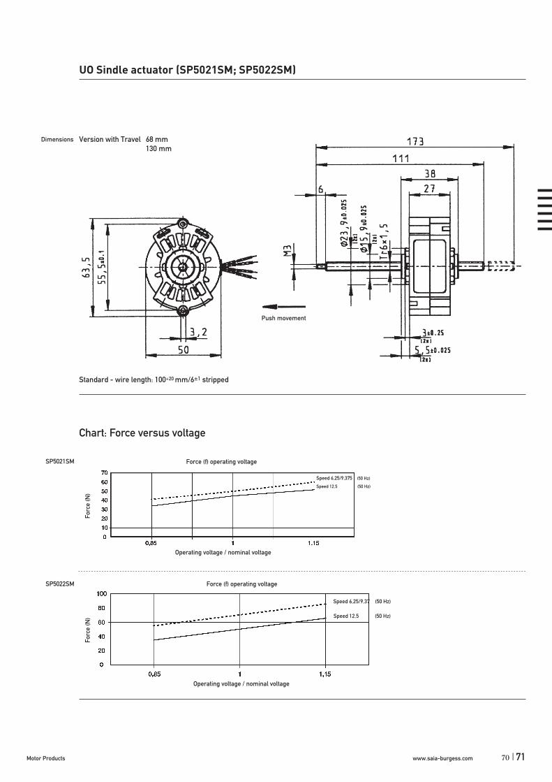
UO Sindle actuator (SP5021SM; SP5022SM)
Dimensions (mm)
Travel (mm)
Voltage (V)
Thread pitch (mm)
Speed (mm/s)50 Hz60 Hz
Pole number
Max. Force (N)*
50 x 27
68–130
12–230
1,5/1,5/1,5
6,25/9,375/12,57,5/11,25/15
24/16/12
45–50 (SP5021SM); 50–70 (SP5022SM)
* Depends on winding, frequency and lifetime required. Drive against end stops only permissible after clarification of operating conditions and approval by Saia-Burgess.
Standard Data
Climatic class wide-spread according to DIN IEC 60721-2-1Ambient temperature operation °C -15 ... +40Ambient temperature storage °C -20 ... +100Thermal class A according to DIN EN 60085Winding coil temperature increase K 85Approval standardMounting any positionElectrical connection cableProtection IP 40 according to DIN EN 60529Weight ~ 220 g Rotor stalling motor can be stopped when voltage is applied, without being overheatedBearings ball bearing
Type
Nominal Voltage
Speed at 50 Hz
Travel
Synchronous Motor SP5021SM / SP5022SM 24 V 6,25 mm/s 68 mm
24 V 50/60 Hz110 V 50/60 Hz230 V 50/60 Hz
6,25 mm/s9,375 mm/s12,5 mm/s
68 mm130 mm
Order Reference
68
www.saia-burgess.com Motor Products70 |
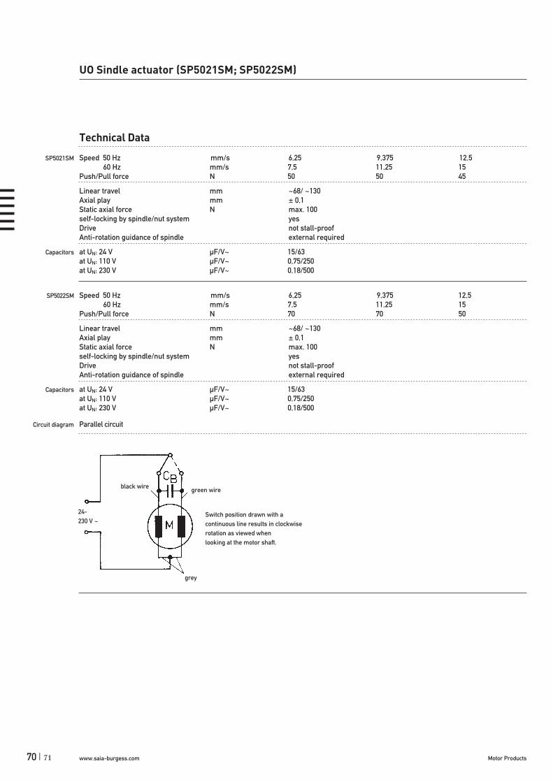
UO Sindle actuator (SP5021SM; SP5022SM)
Technical Data
SP5021SM Speed 50 Hz mm/s 6,25 9,375 12,5 60 Hz mm/s 7,5 11,25 15Push/Pull force N 50 50 45
Linear travel mm ~68/ ~130Axial play mm ± 0,1Static axial force N max. 100self-locking by spindle/nut system yesDrive not stall-proofAnti-rotation guidance of spindle external required
Capacitors at UN: 24 V μF/V~ 15/63at UN: 110 V μF/V~ 0,75/250at UN: 230 V μF/V~ 0,18/500
SP5022SM Speed 50 Hz mm/s 6,25 9,375 12,5 60 Hz mm/s 7,5 11,25 15Push/Pull force N 70 70 50
Linear travel mm ~68/ ~130Axial play mm ± 0,1Static axial force N max. 100self-locking by spindle/nut system yesDrive not stall-proofAnti-rotation guidance of spindle external required
Capacitors at UN: 24 V μF/V~ 15/63at UN: 110 V μF/V~ 0,75/250at UN: 230 V μF/V~ 0,18/500
Circuit diagram Parallel circuit
24-230 V ~
black wire green wire
Switch position drawn with acontinuous line results in clockwise rotation as viewed whenlooking at the motor shaft.
grey
71
www.saia-burgess.comMotor Products | 71
Forc
e (N
)
Force (f) operating voltage
Operating voltage / nominal voltage
Speed 6,25/9,37 (50 Hz)
Speed 12,5 (50 Hz)
SP5021SM
SP5022SM
UO Sindle actuator (SP5021SM; SP5022SM)
Forc
e (N
)
Force (f) operating voltage
Operating voltage / nominal voltage
Dimensions
Push movement
Standard - wire length: 100+20 mm/6±1 stripped
Version with Travel 68 mm 130 mm
70


www.saia-burgess.comMotor Products | 73
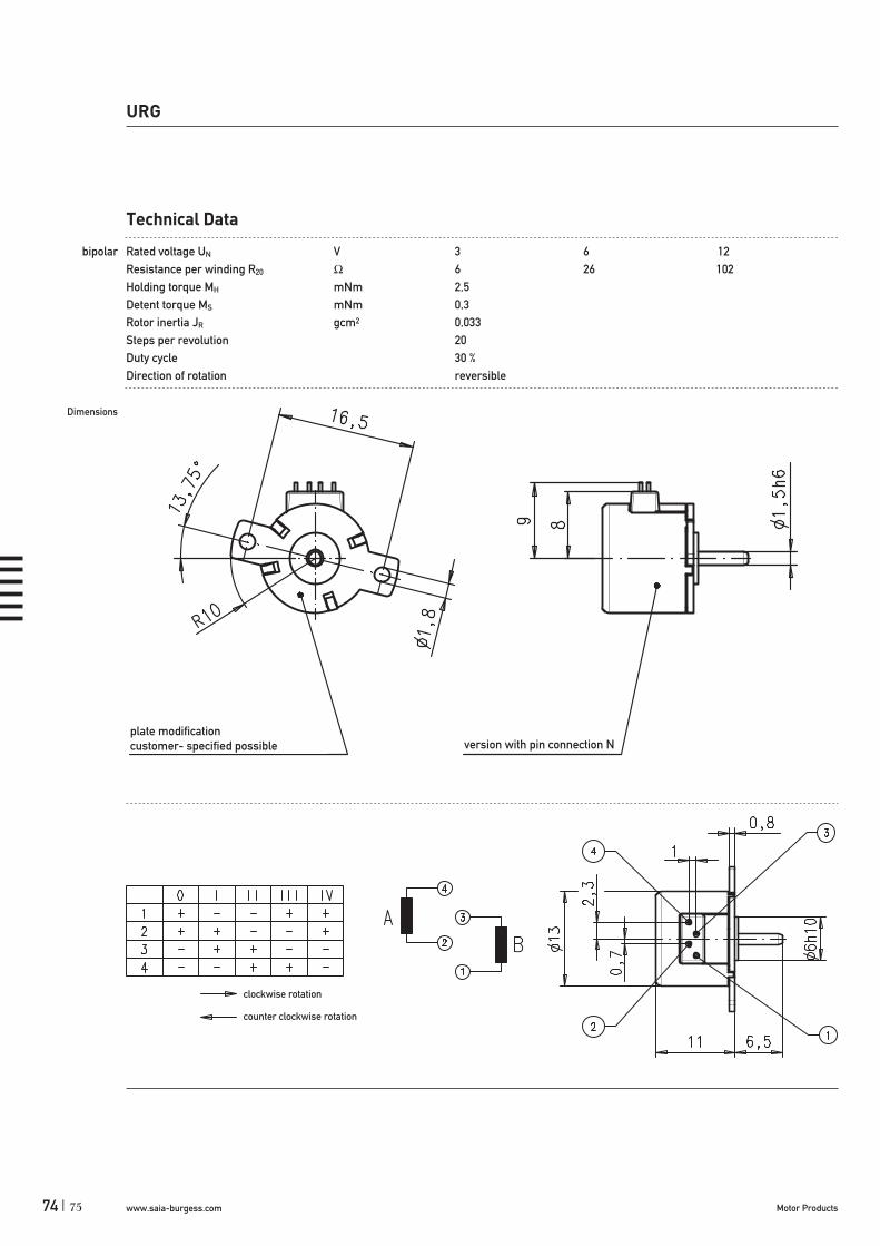
URG
Dimensions (mm)
Step angle (°)
Holding torque * (mNm)
Detent torque (mNm)
Winding
Gear combination
URGStepper Motors
Rotational
13 x 11
18
2,0
0,3
bipolar
–
* winding for duty cycle 30 %, standard magnet
Standard Data
Climatic class wide-spread according to DIN IEC 60721-2-1Ambient temperature operation °C -15 ... +60Ambient temperature storage °C -20 ... +100Thermal resistance at f=0 Rtherm 83 K/WThermal class B according to DIN EN 60085Approval standardMounting any positionElectrical connection Pin, optional flex printProtection IP 40 according to DIN EN 60529Weight 7 g Rotor stalling motor can be stopped when voltage is applied, without being overheatedBearings integrated high temperature plastic bearing
Stepper Motor URG 1E N 6 R C
1E bipolar, standard magnet5E bipolar, stronger magnet
N
see next page
R reversible
N PinC flex print
This motor type doesn’t fulfil basis insulation requirements of EN 60335-1: 2004Customer application must realize a suitable protection class.
Type
Configuration
Approval
Resistance
Direction
Connector
Order Reference
72
www.saia-burgess.com Motor Products74 |
URG
Technical Data
bipolar Rated voltage UN V 3 6 12Resistance per winding R20 6 26 102Holding torque MH mNm 2,5Detent torque MS mNm 0,3Rotor inertia JR gcm2 0,033Steps per revolution 20Duty cycle 30 %Direction of rotation reversible
Dimensions
clockwise rotation
counter clockwise rotation
plate modification customer- specified possible version with pin connection N
75
www.saia-burgess.comMotor Products | 75
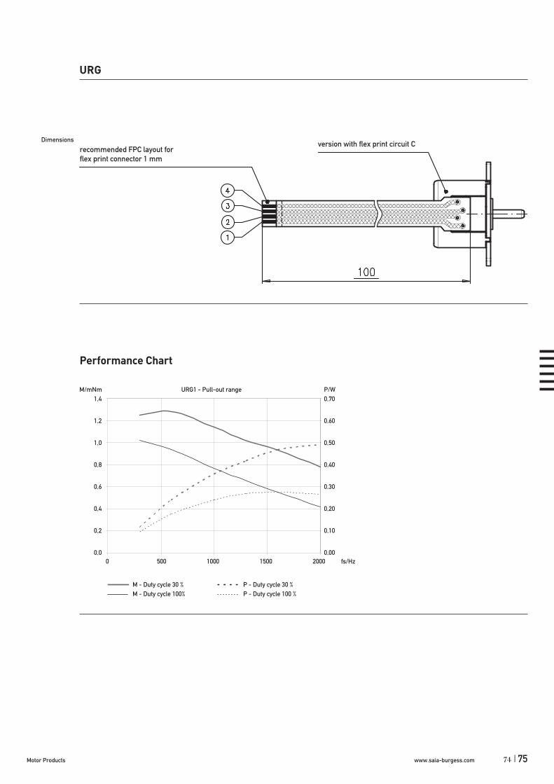
M - Duty cycle 30 % P - Duty cycle 30 %M - Duty cycle 100% P - Duty cycle 100 %
Performance Chart
M/mNm URG1 - Pull-out range P/W1,4 0,70
1,2 0,60
1,0 0,50
0,8 0,40
0,6 0,30
0,4 0,20
0,2 0,10
0,0 0,00
URG
Dimensions
0 500 1000 1500 2000 fs/Hz
recommended FPC layout for flex print connector 1 mm
version with flex print circuit C
74

www.saia-burgess.com Motor Products76 |
UAG1/2Stepper Motors
Rotational
UAG1/2
Dimensions (mm)
Step angle (°)
Holding torque (cNm)
Detent torque (cNm)
Winding
Gear combination
20 x 17,2
18
0,7 / 0,5
0,14
bipolar/unipolar
on request
Standard Data
Climatic class wide-spread according to DIN IEC 60721-2-1
Ambient temperature operation °C -40...+60Ambient temperature storage °C -40...+100Thermal resistance at f=0 Rtherm 50 K/W
Thermal class B according to DIN EN 60085
Approval standard
Mounting any position
Electrical connection insulation displacement connection, pins, lead wires
Protection IP 40 according to DIN EN 60529
Weight 25 g
Rotor stalling motor can be stopped when voltage is applied, without being overheated
Bearings sintered bronze, self-lubricating
Type
Configuration
Rotor shaft, mounting
Approval
Resistance
Direction
Cable
Stepper Motor UAG 1 0 N 27 ( ) R E
1 bipolar2 unipolar
0 centring 8 mm, mounting plate with screw M23 centring 8 mm, mounting plate with long holesA centring 6 mm, mounting plate with screw M2E centring 6 mm, mounting plate with long holes
N Approval Standard
See next page Resistance per winding for bipolar or unipolar.
reversible
E Lead wires 150 mm with plug AMP MicroMatch 0-215083-6 (other on request)
Order Reference
77

www.saia-burgess.comMotor Products | 77
Technical Data
bipolar (UAG1) Rated voltage UN V 6 12 24
Resistance per winding R20 27 150 675
unipolar (UAG2) Rated voltage UN V 6 12 24
Resistance per winding R20 35 170 700
Steps per revolution 20
Duty cycle 100%
Winding temperature Tmax 130° C
Rotor inertia JR 0,31 gcm2
Holding torque MH 0,7 cNm (UAG1) 0,5 cNm (UAG2)
Detent torque MD 0,14 cNm
Direction of rotation reversible
Dimensions
UAG1/2
Pin 6...1
Connector flat ribboncable to the left/rightor looped
Connector option Kwith contact pin
Mounting with screw plate
76

www.saia-burgess.com Motor Products78 |
Performance Chart
UAG1 - Pull-in range
0
0.1
0.2
0.3
0.4
0.5
0.6
0.7
0.8
0 100 200 300 400 500 600fS/ Hz
M/ cNm
0.00
0.05
0.10
0.15
0.20
0.25
0.30
0.35
0.40P/ W
UAG1 - Pull-out range
0.0
0.1
0.2
0.3
0.4
0.5
0.6
0.7
0 100 200 300 400 500 600 700 800fS/ Hz
M/ cNm
0.00
0.10
0.20
0.30
0.40
0.50
0.60
0.70P/ W
UAG2 - Pull-in range
0.0
0.1
0.2
0.3
0.4
0.5
0 50 100 150 200 250 300 350 400 450 500fS/ Hz
M/ cNm
0.00
0.05
0.10
0.15
0.20
0.25
P/ W
UAG2 - Pull-out range
0.0
0.1
0.2
0.3
0.4
0.5
0.6
0 100 200 300 400 500 600 700 800fS/ Hz
M/ cNm
0.00
0.10
0.20
0.30
0.40
0.50
0.60
P/ W
UAG1/2
M - Duty cycle 30 % P - Duty cycle 30 %M - Duty cycle 100% P - Duty cycle 100 %
79
www.saia-burgess.comMotor Products | 79
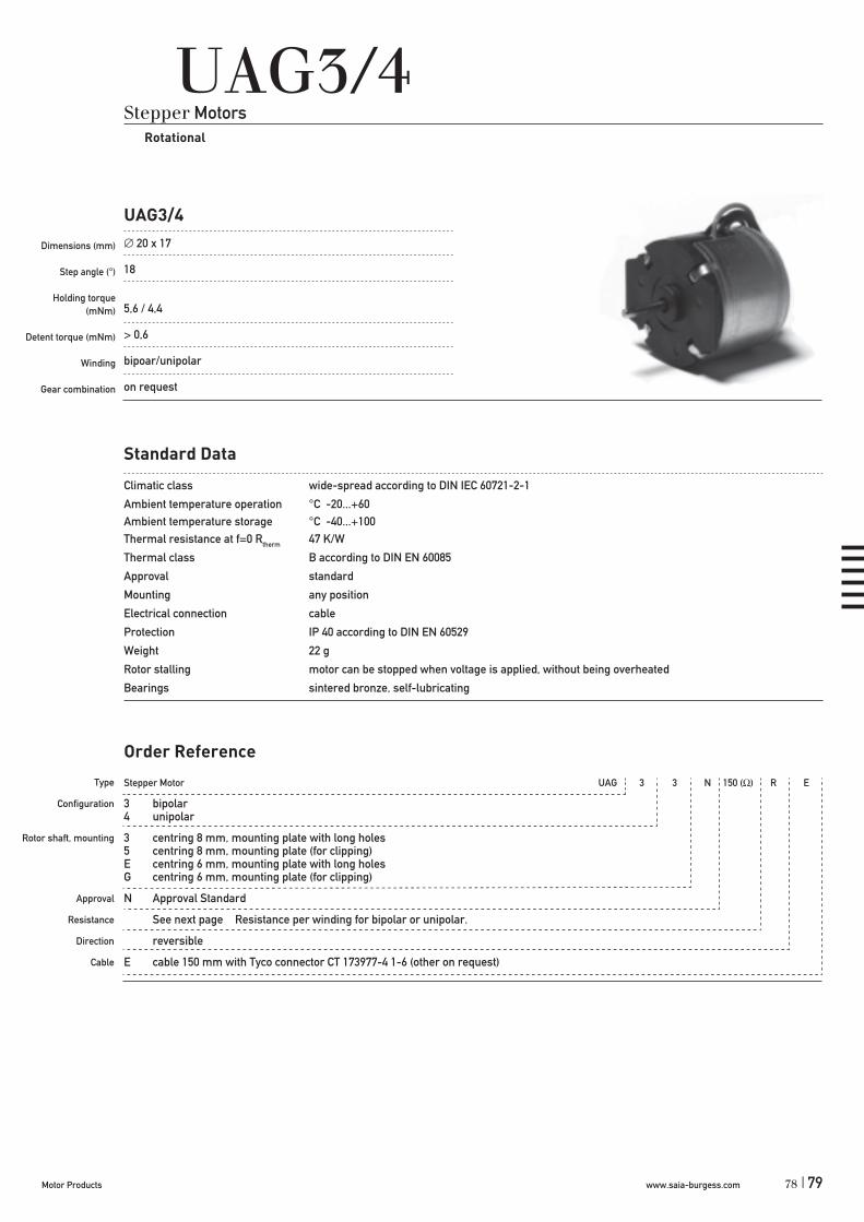
UAG3/4Stepper Motors
Rotational
UAG3/4
Dimensions (mm)
Step angle (°)
Holding torque (mNm)
Detent torque (mNm)
Winding
Gear combination
20 x 17
18
5,6 / 4,4
> 0,6
bipoar/unipolar
on request
Standard Data
Climatic class wide-spread according to DIN IEC 60721-2-1
Ambient temperature operation °C -20...+60Ambient temperature storage °C -40...+100Thermal resistance at f=0 Rtherm 47 K/W
Thermal class B according to DIN EN 60085
Approval standard
Mounting any position
Electrical connection cable
Protection IP 40 according to DIN EN 60529
Weight 22 g
Rotor stalling motor can be stopped when voltage is applied, without being overheated
Bearings sintered bronze, self-lubricating
Type
Configuration
Rotor shaft, mounting
Approval
Resistance
Direction
Cable
Stepper Motor UAG 3 3 N 150 ( ) R E
3 bipolar4 unipolar
3 centring 8 mm, mounting plate with long holes5 centring 8 mm, mounting plate (for clipping)E centring 6 mm, mounting plate with long holesG centring 6 mm, mounting plate (for clipping)
N Approval Standard
See next page Resistance per winding for bipolar or unipolar.
reversible
E cable 150 mm with Tyco connector CT 173977-4 1-6 (other on request)
Order Reference
78

www.saia-burgess.com Motor Products80 |
Technical Data
bipolar (UAG3) Rated voltage UN V 12
Resistance per winding R20 150
unipolar (UAG4) Rated voltage UN V 12
Resistance per winding R20 150
Steps per revolution 20
Duty cycle 100%
Winding temperature Tmax 130° C
Rotor inertia JR 0,26 gcm2
Holding torque MH 0,56 cNm (UAG3) 0,44 cNm (UAG4)
Detent torque MH > 0,6 mNm
Direction of rotation reversible
Dimensions
UAG3/4
motortype D
UAG33 8 h8UAG3E 6 h8
motortype D
UAG43 8 h8UAG4E 6 h8
CT connector 2mm
AMP - 173977-4 (bipolar)AMP - 173977-6 (unipolar)
0 I II III IV
1 + + - - +
2 + - - + +
3 - - + + -
4 - + + - -
bipolar
clockwise rotation counter clockwise rotation
0 I II III IV
1 – – + + –
2 – + + – –
3 Un Un Un Un Un
4 Un Un Un Un Un
5 + + – – +
6 + – – + +
unipolar
clockwise rotation counter clockwise rotation
81
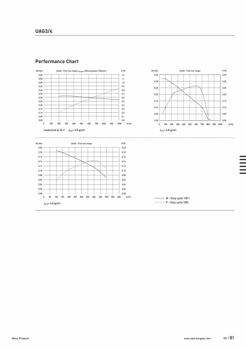
www.saia-burgess.comMotor Products | 81
Performance Chart
measured at 36 V Jext= 4,8 gcm2 Jext= 4,8 gcm2
Jext= 4,8 gcm2
UAG3/4
M/cNm UAG3 - Pull-out range P/W
0,35 0,35
0,30 0,30
0,25 0,25
0,20 0,20
0,15 0,15
0,10 0,10
0,05 0,05
0,00 0,00
0 100 200 300 400 500 600 700 800 900 1000 fs/Hz
M/cNm UAG3 - Pull-out range Ichopper=55mA/phase (150ohm) P/W
0,60 1,2
0,55 1,1
0,50 1,0
0,45 0,9
0,40 0,8
0,35 0,7
0,30 0,6
0,25 0,5
0,20 0,4
0,15 0,3
0,10 0,2
0,05 0,1
0,00 0,00 100 200 300 400 500 600 700 800 900 1000 fs/Hz
M/cNm UAG4 - Pull-out range P/W
0,20 0,20
0,18 0,18
0,16 0,16
0,14 0,14
0,12 0,12
0,10 0,10
0,08 0,08
0,06 0,06
0,04 0,04
0,02 0,02
0,00 0,000 50 100 150 200 250 300 350 400 450 500 550 600 fs/Hz M - Duty cycle 100 %
P - Duty cycle 100%
80

www.saia-burgess.com Motor Products82 |
Stepper Motor UCD 1 0 N 24 R B
1 bipolar, standard magnet 5 bipolar, stronger magnet2 unipolar, standard magnet 6 unipolar, stronger magnet
0 centring 8 mm, shaft 2,0 mm, screw plate A centring 10 mm, shaft 2,0 mm, screw plate1 centring 8 mm, shaft 1,5 mm, screw plate C centring 10 mm, shaft 1,5 mm, screw plate3 centring 8 mm, shaft 2,0 mm, clip E centring 10 mm, shaft 2,0 mm, clip4 centring 8 mm, shaft 1,5 mm, clip K centring 10 mm, shaft 1,5 mm, clip
N Approval Standard
see next page; Resistance per winding for bipolar or unipolar
R reversible
D see page 129 „Connection Types“N
UCD1/5; UCD2/6
Dimensions (mm)
Step angle (°)
Holding torque *(cNm)
Detent torque (cNm)
Winding
Gear combination
UCDStepper Motors
Rotational
28 x 24
7,5
1,6–2,7
0,26–0,42
bipolar/unipolar
on request
* values for lead wire version (connection N) / connector versions up to 15 % higher
Standard Data
Climatic class wide-spread according to DIN IEC 60721-2-1Ambient temperature operation °C -15 ... +60Ambient temperature storage °C -20 ... +100Thermal resistance at f=0 Rtherm 29 K/WThermal class B according to DIN EN 60085Approval standardMounting any positionElectrical connection connector type D or NProtection IP 40 according to DIN EN 60529Weight 54 g Rotor stalling motor can be stopped when voltage is applied, without being overheatedBearings Sintered bronze, self- lubricating
Type
Configuration
Rotor shaft, mounting
Approval
Resistance
Direction
Connection
Order Reference
83

www.saia-burgess.comMotor Products | 83
UCD1/5; UCD2/6
Technical Data
bipolar UCD1 UCD5Holding torque MH * cNm 2 2,7Detent torque MS cNm 0,26 0,42Rotor inertia JR gcm2 2,2 2,4
Rated voltage UN V 6 12 24Resistance per winding R20 24 90 380Steps per revolution 48Duty cycle 100%Direction of rotation V reversible
unipolar UCD2 UCD6Holding torque MH mNm 1,6 2,3Detent torque MS mNm 0,26 0,42Rotor inertia JR gcm2 2,2 2,4
Rated voltage UN V 3 6 24Resistance per winding R20 24 90 380Steps per revolution 48Duty cycle 100%Direction of rotation V reversible
* values for lead wire version (connection N) / connector versions up to 15 % higher
Circuit diagram bipolar
unipolar
counter clockwise rotation
clockwise rotation
counter clockwise rotation
clockwise rotation
82

www.saia-burgess.com Motor Products84 |
UCD1/5; UCD2/6
85
Dimensions Version with Connector D
Version with Connector N
D 8 mm 10 mm
D 8 mm 10 mm

www.saia-burgess.comMotor Products | 85
M/cNm UCD5 - Pull-out range P/W
2,5 1,25
2,0 1,00
1,5 0,75
1,0 0,5
0,5 0,25
0,0 0,000 100 200 300 400 500 600 700 fs/Hz
M/cNm UCD6 - Pull-in range P/W
2,0 1,00
1,8 0,90
1,6 0,80
1,4 0,70
1,2 0,60
1,0 0,50
0,8 0,40
0,6 0,30
0,4 0,20
0,2 0,10
0,0 0,000 50 100 150 200 250 300 350 400 fs/Hz
M/cNm UCD1 - Pull-out range P/W
2,0 0,50
1,8 0,45
1,6 0,40
1,4 0,35
1,2 0,30
1,0 0,25
0,8 0,20
0,6 0,15
0,4 0,10
0,2 0,05
0,0 0,000 100 200 300 400 500 600 fs/Hz
M/cNm UCD1 - Pull-in range P/W
2,0 0,50
1,8 0,45
1,6 0,40
1,4 0,35
1,2 0,30
1,0 0,25
0,8 0,20
0,6 0,15
0,4 0,10
0,2 0,05
0,0 0,000 50 100 150 200 250 300 350 400 450 fs/Hz
UCD1/5; UCD2/6
Performance Chart
M/cNm UCD2 - Pull-in range P/W
1,4 0,70
1,2 0,60
1,0 0,50
0,8 0,40
0,6 0,30
0,4 0,20
0,2 0,10
0,0 0,000 50 100 150 200 250 300 350 400 fs/Hz
M/cNm UCD2 - Pull-out range P/W
1,6 0,80
1,4 0,70
1,2 0,60
1,0 0,50
0,8 0,40
0,6 0,30
0,4 0,20
0,2 0,10
0,0 0,000 100 200 300 400 500 600 fs/Hz
M/cNm UCD5 - Pull-in range P/W
2,5 1,25
2,0 1,00
1,5 0,75
1,0 0,5
0,5 0,25
0,0 0,000 100 200 300 400 500 fs/Hz
M/cNm UCD6 - Pull-out range P/W
2,0 1,00
1,8 0,90
1,6 0,80
1,4 0,70
1,2 0,60
1,0 0,50
0,8 0,40
0,6 0,30
0,4 0,20
0,2 0,10
0,0 0,000 100 200 300 400 500 600 fs/Hz
0
0
0
0
1
1
M - Duty cycle 30 % P - Duty cycle 30 %M - Duty cycle 100% P - Duty cycle 100 %
84

www.saia-burgess.com Motor Products86 |
Stepper Motor UCB 1 0 N 24 R B
1 bipolar, standard magnet 5 bipolar, stronger magnet2 unipolar, standard magnet 6 unipolar, stronger magnet
0 centring 8 mm, shaft 2,0 mm, screw plate A centring 10 mm, shaft 2,0 mm, screw plate1 centring 8 mm, shaft 1,5 mm, screw plate C centring 10 mm, shaft 1,5 mm, screw plate3 centring 8 mm, shaft 2,0 mm, clip E centring 10 mm, shaft 2,0 mm, clip4 centring 8 mm, shaft 1,5 mm, clip K centring 10 mm, shaft 1,5 mm, clip
N Approval Standard
see next page; Resistance per winding for bipolar or unipolar
R reversible
D see page 129 „Connection Types“N
UCB1/5; UCB2/6
Dimensions (mm)
Step angle (°)
Holding torque * (cNm)
Detent torque (cNm)
Winding
Gear combination
UCBStepper Motors
Rotational
28 x 24
15
1,3–2,3
0,29
bipolar/unipolar
on request
* values for lead wire version (connection N) / connector versions up to 15 % higher
Standard Data
Climatic class wide-spread according to DIN IEC 60721-2-1Ambient temperature operation °C -15 ... +60Ambient temperature storage °C -20 ... +100Thermal resistance at f=0 Rtherm 29 K/WThermal class B according to DIN EN 60085Approval standardMounting any positionElectrical connection connector type D or NProtection IP 40 according to DIN EN 60529Weight 54 g Rotor stalling motor can be stopped when voltage is applied, without being overheatedBearings Sintered bronze, self- lubricating
Type
Configuration
Rotor shaft, mounting
Approval
Resistance
Direction
Connection
Order Reference
87

www.saia-burgess.comMotor Products | 87
UCB1/5; UCD2/6
Technical Data
bipolar UCB1 UCB5Holding torque MH * cNm 1,7 2,3Detent torque MS cNm 0,29 0,46Rotor inertia JR gcm2 2,1 2,4
Rated voltage UN V 6 12 24Resistance per winding R20 24 90 380Steps per revolution 24Duty cycle 100%Direction of rotation V reversible
unipolar UCB2 UCB6Holding torque MH * mNm 1,3 1,8Detent torque MS mNm 0,29 0,46Rotor inertia JR gcm2 2,1 2,4
Rated voltage UN V 6 12 24Resistance per winding R20 24 90 380Steps per revolution 24Duty cycle 100%Direction of rotation V reversible
* values for lead wire version (connection N) / connector versions up to 15 % higher
Circuit diagram bipolar
unipolar
counter clockwise rotation
clockwise rotation
counter clockwise rotation
clockwise rotation
86
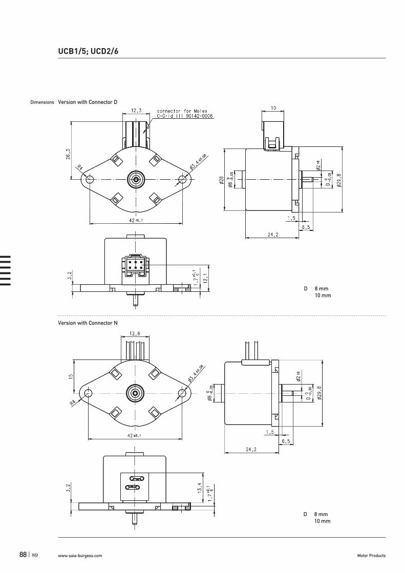
www.saia-burgess.com Motor Products88 |
UCB1/5; UCD2/6
89
Dimensions Version with Connector D
Version with Connector N
D 8 mm 10 mm
D 8 mm 10 mm

www.saia-burgess.comMotor Products | 89
M/cNm UCB1 - Pull-out range P/W
1,8 0,90
1,6 0,80
1,4 0,70
1,2 0,60
1,0 0,50
0,8 0,40
0,6 0,30
0,4 0,20
0,2 0,10
0,0 0,000 100 200 300 400 500 600 fs/Hz
M/cNm UCB1 - Pull-in range P/W
1,6 0,80
1,4 0,70
1,2 0,60
1,0 0,50
0,8 0,40
0,6 0,30
0,4 0,20
0,2 0,10
0,0 0,000 50 100 150 200 250 300 350 fs/Hz
UCB1/5; UCD2/6
Performance Chart
M/cNm UCB2 - Pull-in range P/W
1,2 0,60
1,0 0,50
0,8 0,40
0,6 0,30
0,4 0,20
0,2 0,10
0,0 0,000 50 100 150 200 250 300 fs/Hz
M/cNm UCB2 - Pull-out range P/W
1,4 0,70
1,2 0,60
1,0 0,50
0,8 0,40
0,6 0,30
0,4 0,20
0,2 0,10
0,0 0,000 100 200 300 400 500 600 fs/Hz
M/cNm UCB5 - Pull-in range P/W
2,5 1,25
2,0 1,00
1,5 0,75
1,0 0,5
0,5 0,25
0,0 0,000 50 100 150 200 250 300 350 fs/Hz
M/cNm UCB5 - Pull-out range P/W
2,5 1,25
2,0 1,00
1,5 0,75
1,0 0,5
0,5 0,25
0,0 0,000 100 200 300 400 500 fs/Hz
M/cNm UCB6 - Pull-in range P/W
1,8 0,90
1,6 0,80
1,4 0,70
1,2 0,60
1,0 0,50
0,8 0,40
0,6 0,30
0,4 0,20
0,2 0,10
0,0 0,000 50 100 150 200 250 300 fs/Hz
M/cNm UCB6 - Pull-out range P/W
1,8 0,90
1,6 0,80
1,4 0,70
1,2 0,60
1,0 0,50
0,8 0,40
0,6 0,30
0,4 0,20
0,2 0,10
0,0 0,000 100 200 300 400 500 600 fs/Hz
M - Duty cycle 30 % P - Duty cycle 30 %M - Duty cycle 100% P - Duty cycle 100 %
88

www.saia-burgess.com Motor Products90 |
Type
Configuration
Rotor shaft, mounting
Approval
Resistance
Direction
Cable
Stepper Motor UBD 1 0 N 18,5 R E
1 bipolar, standard magnet 5 bipolar, stronger magnet2 unipolar, standard magnet 6 unipolar, stronger magnet
0 centring 8 mm, shaft 2,0 mm, clip A centring 10 mm, shaft 2,0 mm, clip1 centring 8 mm, shaft 1,5 mm, clip C centring 10 mm, shaft 1,5 mm, clip3 centring 8 mm, shaft 2,0 mm, screw plate E centring 10 mm, shaft 2,0 mm, screw plate4 centring 8 mm, shaft 1,5 mm, screw plate K centring 10 mm, shaft 1,5 mm, screw plate
N Approval Standard
See next page Resistance per winding for bipolar or unipolar.
reversible
E cable 150 mm (other on request)
UBDStepper Motors
Rotational
Standard Data
Climatic class wide-spread according to DIN IEC 60721-2-1
Ambient temperature operation °C -15...+55Ambient temperature storage °C -20...+100Thermal resistance at f=0 Rtherm 27 K/W
Thermal class A according to DIN EN 60085
Approval standard (UL/CSA on request)
Mounting any position
Electrical connection cable
Protection IP 40 according to DIN EN 60529
Weight 60 g
Rotor stalling motor can be stopped when voltage is applied, without being overheated
Bearings sintered bronze, self-lubricating
Electric strength according to DIN EN 60034-1/DIN EN 60335-1
Order Reference
UBD1/2/5/6
Dimensions (mm)
Step angle (°)
Holding torque (cNm)
Detent torque (cNm)
Winding
Gear combination
36 x 21
7.5
1.3–1.9
0.22/0.27
bipolar/unipolar
A, D, M, B, F, V
91

www.saia-burgess.comMotor Products | 91
Technical Data
bipolar (UBD1/5) Rated voltage UN V 3 6 12 24
Resistance per winding R20 11,5 18,5 100 460
Holding torque MH cNm 1,8 (UBD1); 1,9 (UBD5)
Detent torque MS cNm 0,22 (UBD1); 0,27 (UBD5)
Rotor inertia JR gcm2 2,8 (UBD 1), 2,9 (UBD 5)
unipolar (UBD2/6) Rated voltage UN V 3 6 12 24
Resistance per winding R20 12 28 120 500
Holding torque MH cNm 1,3 (UBD2); 1,6 (UBD6)
Detent torque MS cNm 0,22 (UBD2); 0,27 (UBD6)
Rotor inertia JR gcm2 2,8 (UBD2); 2,9 (UBD6)
Steps per revolution 48
Winding temperature Tmax 105° C
Duty cycle 100%
Direction of rotation reversible
Dimensions
UBD1/2/5/6
ø80 -0,05
øDøZ0 -0,05
ø36
1,5
6,15
420,0
5
3,60,0
5
48
1,56,5
21 0,2
0,8
øY
min. 8
5 +0-0,1
52,5
0,5
48+0 -0
,5
max.25,3
Plate cut-out
0,4
1...1,8
max. 2,3
Mounting with snap on clipMounting with screw plate
48
ø36
420,0
5
3,2+0
,1-0
10
6,86
Mounting with screw plate
FF
90

www.saia-burgess.com Motor Products92 |
Performance Chart
UBD1/2/5/6
0.0
0.2
0.4
0.6
0.8
1.0
1.2
1.4
0 100 200 300 400 500 600 700fS/ Hz
M/ cNm
0.00
0.10
0.20
0.30
0.40
0.50
0.60
0.70P/ W
UBD1 - Pull-in range UBD1 - Pull-out range
0.0
0.2
0.4
0.6
0.8
1.0
1.2
1.4
1.6
0 100 200 300 400 500 600 700 800fS/ Hz
M/ cNm
0.00
0.10
0.20
0.30
0.40
0.50
0.60
0.70
0.80P/ W
UBD2 - Pull-in range
0.0
0.1
0.2
0.3
0.4
0.5
0.6
0.7
0.8
0.9
1.0
0 100 200 300 400 500 600fS/ Hz
M/ cNm
0.00
0.05
0.10
0.15
0.20
0.25
0.30
0.35
0.40
0.45
0.50P/ W
0.0
0.2
0.4
0.6
0.8
1.0
1.2
0 100 200 300 400 500 600 700 800fS/ Hz
M/ cNm
0.00
0.10
0.20
0.30
0.40
0.50
0.60
P/ W
UBD2 - Pull-out range
100 200 300 400 500 600 700fS/ Hz
0.00
0.10
0.20
0.30
0.40
0.50
0.60
0.70
0.80P/ W
UBD5 - Pull-in range
0.0
0.2
0.4
0.6
0.8
1.0
1.2
1.4
1.6
0
M/ cNm
0.0
0.2
0.4
0.6
0.8
1.0
1.2
1.4
1.6
1.8
0 100 200 300 400 500 600fS/ Hz
M/ cNm
UBD5 - Pull-out range
7000.00
0.10
0.20
0.30
0.40
0.50
0.60
0.70
0.80
0.90P/ W
UBD6 - Pull-in range
100 200 300 400 500 600fS/ Hz
0.00
0.10
0.20
0.30
0.40
0.50
0.60
0.70P/ W
0.0
0.2
0.4
0.6
0.8
1.0
1.2
1.4
0
M/ cNm
UBD6 - Pull-out range
0.0
0.2
0.4
0.6
0.8
1.0
1.2
1.4
1.6
0 100 200 300 400 500 600 700 800fS/ Hz
M/ cNm
0.00
0.10
0.20
0.30
0.40
0.50
0.60
0.70
0.80P/ W
M - Duty cycle 30 % P - Duty cycle 30 %M - Duty cycle 100% P - Duty cycle 100 %
93
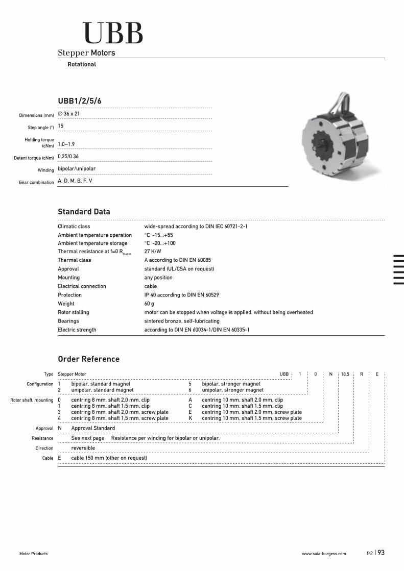
www.saia-burgess.comMotor Products | 93
UBBStepper Motors
Rotational
Standard Data
Climatic class wide-spread according to DIN IEC 60721-2-1
Ambient temperature operation °C -15...+55Ambient temperature storage °C -20...+100Thermal resistance at f=0 Rtherm 27 K/W
Thermal class A according to DIN EN 60085
Approval standard (UL/CSA on request)
Mounting any position
Electrical connection cable
Protection IP 40 according to DIN EN 60529
Weight 60 g
Rotor stalling motor can be stopped when voltage is applied, without being overheated
Bearings sintered bronze, self-lubricating
Electric strength according to DIN EN 60034-1/DIN EN 60335-1
Type
Configuration
Rotor shaft, mounting
Approval
Resistance
Direction
Cable
Stepper Motor UBB 1 0 N 18,5 R E
1 bipolar, standard magnet 5 bipolar, stronger magnet2 unipolar, standard magnet 6 unipolar, stronger magnet
0 centring 8 mm, shaft 2,0 mm, clip A centring 10 mm, shaft 2,0 mm, clip1 centring 8 mm, shaft 1,5 mm, clip C centring 10 mm, shaft 1,5 mm, clip3 centring 8 mm, shaft 2,0 mm, screw plate E centring 10 mm, shaft 2,0 mm, screw plate4 centring 8 mm, shaft 1,5 mm, screw plate K centring 10 mm, shaft 1,5 mm, screw plate
N Approval Standard
See next page Resistance per winding for bipolar or unipolar.
reversible
E cable 150 mm (other on request)
Order Reference
UBB1/2/5/6
Dimensions (mm)
Step angle (°)
Holding torque (cNm)
Detent torque (cNm)
Winding
Gear combination
36 x 21
15
1.0–1.9
0.25/0.36
bipolar/unipolar
A, D, M, B, F, V
92

www.saia-burgess.com Motor Products94 |
Technical Data
bipolar (UBB1/5) Rated voltage UN V 3 6 12 24
Resistance per winding R20 11,5 18,5 100 460
Holding torque MH cNm 1,5 (UBB1); 1,9 (UBB5)
Detent torque MS cNm 0,25 (UBB1); 0,36 (UBB5)
Rotor inertia JR gcm2 2,8 (UBB1); 2,9 (UBB5)
unipolar (UBB2/6) Rated voltage UN V 3 6 12 24
Resistance per winding R20 12 28 120 500
Holding torque MH cNm 1,0 (UBB2); 1,4 (UBB6)
Detent torque MS cNm 0,25 (UBB2); 0,36 (UBB6)
Rotor inertia JR gcm2 2,8 (UBB2), 2,9 (UBB6)
Steps per revolution 24
Winding temperature Tmax 105°C
Duty cycle 100%
Direction of rotation reversible
Dimensions
UBB1/2/5/6
ø80 -0,05
øDøZ0 -0,05
ø36
1,5
6,15
420,0
5
3,60,0
5
48
1,56,5
21 0,2
0,8
øY
min. 8
5 +0-0,1
52,5
0,5
48+0 -0
,5max.25,3
Plate cut-out
0,4
1...1,8
max. 2,3
Mounting with snap on clipMounting with screw plate
48
ø36
420,0
5
3,2+0
,1-0
10
6,86
Mounting with screw plate
FF
95

www.saia-burgess.comMotor Products | 95
UBB1/2/5/6
Performance Chart
0.0
0.2
0.4
0.6
0.8
1.0
1.2
1.4M/ cNm
UBB1 - Pull-in range
0.00
0.10
0.20
0.30
0.40
0.50
0.60
0.70P/ W
0 50 100 150 200 250 300 350 400 450 500fS/ Hz
0.0
0.2
0.4
0.6
0.8
1.0
1.2
1.4M/ cNm
UBB1 - Pull-out range
8000.00
0.10
0.20
0.30
0.40
0.50
0.60
0.70P/ W
0 100 200 300 400 500 600 700fS/ Hz
0.0
0.2
0.4
0.6
0.8
1.0
1.2
M/ cNm
0 50 100 150 200 250 300 350 400 450 500fS/ Hz
0.00
0.10
0.20
0.30
0.40
0.50
0.60P/ W
UBB2 - Pull-in range
0.00
0.20
0.40
0.60
0.80
1.00
1.20
P/ W
0 100 200 300 400 500 600 700 800fS/ Hz
0.0
0.2
0.4
0.6
0.8
1.0
1.2
M/ cNm
UBB2 - Pull-out range
UBB5 - Pull-in range
0.0
0.2
0.4
0.6
0.8
1.0
1.2
1.4
1.6
1.8
2.0
0 50 100 150 200 250 300 350 400fS/ Hz
M/ cNm
0.00
0.10
0.20
0.30
0.40
0.50
0.60
0.70
0.80
0.90
1.00P/ W
UBB5 - Pull-out range
0.0
0.5
1.0
1.5
2.0
2.5
0 100 200 300 400 500 600 700fS/ Hz
M/ cNm
0.00
0.25
0.50
0.75
1.00
1.25
P/ W
UBB6 - Pull-in range
500fS/ Hz
0.00
0.10
0.20
0.30
0.40
0.50
0.60
0.70P/ W
0 50 100 150 200 250 300 350 400 4500.0
0.2
0.4
0.6
0.8
1.0
1.2
1.4M/ cNm
400 500 600 700 800fS/ Hz
0.00
0.10
0.20
0.30
0.40
0.50
0.60
0.70
0.80
0.90P/ W
0.0
0.2
0.4
0.6
0.8
1.0
1.2
1.4
1.6
1.8
0 100 200 300
M/ cNm
UBB6 - Pull-out range
M - Duty cycle 30 % P - Duty cycle 30 %M - Duty cycle 100% P - Duty cycle 100 %
94

www.saia-burgess.com Motor Products96 |
UDBStepper Motors
Rotational
Standard Data
Climatic class wide-spread according to DIN IEC 60721-2-1
Ambient temperature operation °C -15...+60Ambient temperature storage °C -20...+100Thermal resistance at f=0 Rtherm 18 K/W
Thermal class A according to DIN EN 60085
Approval standard
Mounting any position
Electrical connection cable
Protection IP 40 according to DIN EN 60529
Weight 132 g
Rotor stalling motor can be stopped when voltage is applied, without being overheated
Bearings sintered bronze, self-lubricating
Electric strength according to DIN EN 60034-1/DIN EN 60335-1
Type
Configuration
Rotor shaft, mounting
Approval
Resistance
Direction
Cable
Stepper Motor UDB 1 0 N 78 R N
1 bipolar2 unipolar
0 centring 8 mm, shaft 1,5 mm, clip1 centring 8 mm, shaft 2,0 mm, clip
N Approval Standard
See next page Resistance per winding for bipolar or unipolar.
reversible
N cable 150 mm (other on request)
Order Reference
UDB1/2
Dimensions (mm)
Step angle (°)
Holding torque (cNm)
Detent torque (cNm)
Winding
Gear combination
48 x 24
15
2,7/2,2
0.35
bipolar/unipolar
A, D, M, B, F, V, J
97

www.saia-burgess.comMotor Products | 97
Technical Data
bipolar (UDB1) Rated voltage UN V 6 12 24
Resistance per winding R20 15 78 350
Holding torque MH cNm 2,7
Detent torque MS cNm 0,35
Rotor inertia JR gcm2 6,3
unipolar (UDB2) Rated voltage UN V 6 12 24
Resistance per winding R20 19 75 300Holding torque MH cNm 2,2
Detent torque MS cNm 0,35
Rotor inertia JR gcm2 6,3
Steps per revolution 24
Winding temperature Tmax 105° C
Duty cycle 100%
Direction of rotation reversible
Dimensions
UDB1/2
+0,03
5+0
,013
+0,007- 0,007
0-0,006
96

www.saia-burgess.com Motor Products98 |
UDB1/2
Performance Chart
UDB1 - Pull-in range
0.0
0.5
1.0
1.5
2.0
2.5
3.0
0 50 100 150 200 250 300 350 400fS/ Hz
M/ cNm
0.00
0.25
0.50
0.75
1.00
1.25
1.50
P/ W
UDB1 - Pull-out range
0.0
0.5
1.0
1.5
2.0
2.5
3.0
3.5
0 50 100 150 200 250 300 350 400 450 500fS/ Hz
M/ cNm
0.00
0.25
0.50
0.75
1.00
1.25
1.50
1.75P/ W
UDB2 - Pull-in range
0.0
0.5
1.0
1.5
2.0
2.5
0 50 100 150 200 250 300 350 400fS/ Hz
M/ cNm
0.00
0.20
0.40
0.60
0.80
1.00
P/ W
UDB2 - Pull-out range
0.0
0.5
1.0
1.5
2.0
2.5
3.0
0 100 200 300 400 500 600fS/ Hz
M/ cNm
0.00
0.25
0.50
0.75
1.00
1.25
1.50
P/ W
M - Duty cycle 30 % P - Duty cycle 30 %M - Duty cycle 100% P - Duty cycle 100 %
99

www.saia-burgess.comMotor Products | 99
Stepper Motor ST5021 / ST5022 7,5° 7
7,5°11,25°
7
UO (ST5021; ST5022)
Dimensions (mm)
Step angle (°)
Holding torque (cNm)
Detent torque (cNm)
Winding
Gear combination
UOStepper Motors
Rotational
50 x 21
7,5/11,25
3,7–4 (ST5021); 4 (ST5022)
0,25 (ST5021); 1 (ST5022)
bipolar
VK4, UGO/UGP (STG60/61), UGR (STG200), UGS (V250)
Standard Data
Climatic class wide-spread according to DIN IEC 60721-2-1Ambient temperature operation °C -15 ... +40Ambient temperature storage °C -20 ... +100Thermal class B (ST5021); A (ST5022) according to DIN EN 60085Approval standardMounting any positionElectrical connection cableProtection IP 40 according to DIN EN 60529Weight 180 g (ST5021); 195 g (ST5022)Rotor stalling motor can be stopped when voltage is applied, without being overheatedBearings Sintered bronze, self- lubricating
Type
Step angle
Resistance
Order Reference
98

www.saia-burgess.com Motor Products100 |
UO (ST5021; ST5022)
Technical Data
ST5021 Step angle ° 7,5 11,25Rated voltage UN V 4 4Holding torque MH cNm 4 3,7Detent torque Ms cNm 0,25Rotor inertia JR gcm2 14,5
Winding temperature increase K 65Current per winding A 0,53Resistance per winding R20 7Inductance per winding mH 12,5 11,5Power consumption W 4Driver mode Chopper drive
ST5022 Step angle ° 7,5/11,25Rated voltage UN V 4Holding torque MH cNm 7,5Detent torque Ms cNm 1Rotor inertia JR gcm2 25
Winding temperature increase K 65Current per winding A 0,53Resistance per winding R20 7Inductance per winding mH 11Power consumption W 4Driver mode Chopper drive
Circuit diagram Motor connections - bipolar
A
B
A
A1yellow
A2blue
B1red
B2grey
A1A2
B1B2
B
clockwise rotation
101

www.saia-burgess.comMotor Products | 101
ST5022 UOD5 (ST 5022/7,5/1) UOJ5 (ST 5022/11,25/1)
M/cNm M/cNm
fs/Hz fs/Hz
UO (ST5021; ST5022)
Dimensions
Standard - wire length: 100 mmGeneral tolerances acc. to DIN ISO 2768-mk
Performance Chart (chopper driver)
ST5021 UOD1 (ST 5021/7,5/1) UOJ1 (ST 5021/11,25/1)
M/cNm M/cNm
fs/Hz fs/Hz
100

www.saia-burgess.com Motor Products102 |
UFDStepper Motors
Rotational
Standard Data
Climatic class wide-spread according to DIN IEC 60721-2-1
Ambient temperature operation °C -15...+55Ambient temperature storage °C -20...+100Thermal resistance at f=0 Rtherm 13 K/W
Thermal class A according to DIN EN 60085
Approval standard (UL/CSA on request)
Mounting any position
Electrical connection cable
Protection IP 40 according to DIN EN 60529
Weight 180 g
Rotor stalling motor can be stopped when voltage is applied, without being overheated
Bearings sintered bronze, self-lubricating
Electric strength according to DIN EN 60034-1/DIN EN 60335-1
Type
Configuration
Rotor shaft, mounting
Approval
Resistance
Direction
Cable
Stepper Motor UFD 1 0 N 52 R N
1 bipolar, two coils2 unipolar, two coils
0 centring 8 mm, shaft 3,0 mm, clip E centring 10 mm, shaft 3,0 mm, screw plate1 centring 8 mm, shaft 2,0 mm, clip K centring 10 mm, shaft 2,0 mm, screw plate2 centring 8 mm, shaft 1,5 mm, clip M centring 10 mm, shaft 1,5 mm, screw plate3 centring 8 mm, shaft 3,0 mm, screw plate4 centring 8 mm, shaft 2,0 mm, screw plate5 centring 8 mm, shaft 1,5 mm, screw plate
N Approval Standard
See next page Resistance per winding for bipolar or unipolar.
reversible
E cable 150 mm (other on request)
Order Reference
UFD1/2
Dimensions (mm)
Step angle (°)
Holding torque (cNm)
Detent torque (cNm)
Winding
Gear combination
52 x 28
7.5
6,4/6,4
0.45
bipolar/unipolar
A, D, M, B, F, V, J
103

www.saia-burgess.comMotor Products | 103
Technical Data
bipolar (UFD1) Rated voltage UN V 6 12 24
Resistance per winding R20 9,5 52 250
Holding torque MH cNm 6,4
Detent torque MS cNm 0,45
Rotor inertia JR gcm2 14,4
unipolar (UFD2) Rated voltage UN V 6 12 24
Resistance per winding R20 15 61 251
Holding torque MH cNm 4,6
Detent torque MS cNm 0,45
Rotor inertia JR gcm2 14,4
Steps per revolution 48
Winding temperature Tmax 105° C
Duty cycle 100%
Direction of rotation reversible
Dimensions
UFD1/2
FF
F
102

www.saia-burgess.com Motor Products104 |
UFD1/2
Performance Chart
UFD1 - Pull-in range
0
1
2
3
4
5
6
7
0 50 100 150 200 250 300 350 400fS/ Hz
M/ cNm
0.0
0.2
0.4
0.6
0.8
1.0
1.2
1.4P/ W
UFD1 - Pull-out range
0
1
2
3
4
5
6
7
8
0 100 200 300 400 500 600 700fS/ Hz
M/ cNm
0.0
0.2
0.4
0.6
0.8
1.0
1.2
1.4
1.6P/ W
UFD2 - Pull-in range
0
1
2
3
4
5
6
0 50 100 150 200 250 300 350 400 450 500fS/ Hz
M/ cNm
0.0
0.2
0.4
0.6
0.8
1.0
1.2
P/ W
UFD2 - Pull-out range
0
1
2
3
4
5
6
7
0 100 200 300 400 500 600 700 800fS/ Hz
M/ cNm
0.0
0.2
0.4
0.6
0.8
1.0
1.2
1.4P/ W
M - Duty cycle 30 % P - Duty cycle 30 %M - Duty cycle 100% P - Duty cycle 100 %
105

www.saia-burgess.comMotor Products | 105
UFBStepper Motors
Rotational
Type
Configuration
Rotor shaft, mounting
Approval
Resistance
Direction
Cable
Standard Data
Climatic class wide-spread according to DIN IEC 60721-2-1
Ambient temperature operation °C -15...+55Ambient temperature storage °C -20...+100Thermal resistance at f=0 Rtherm 11 K/W (UFB1/2), 7 K/W (UFB3/4)
Thermal class A according to DIN EN 60085
Approval standard (UL/CSA on request)
Mounting any position
Electrical connection cable
Protection IP 40 according to DIN EN 60529
Weight 180 g (UFB1/2), 350 g (UFB3/4)
Rotor stalling motor can be stopped when voltage is applied, without being overheated
Bearings sintered bronze, self-lubricating
Electric strength according to DIN EN 60034-1/DIN EN 60335-1
Order Reference
UFB1/2; UFB3/4
Dimensions (mm)
Step angle (°)
Holding torque (cNm)
Detent torque (cNm)
Winding
Gear combination
52 x 28 / 52 x 56
15
45,3–10,4 (UFB1/2); 7,6–10,4 (UFB3/4)
0.45 (UFB1/2); 0,8 (UFB3/4)
bipolar/unipolar
A, D, M, B, F, V, J
Stepper Motor UFB 1 0 N 52 R N
1 bipolar, two coils 3 bipolar, four coils2 unipolar, two coils 4 unipolar, four coils
0 centring 8 mm, shaft 3,0 mm, clip E centring 10 mm, shaft 3,0 mm, screw plate *1 centring 8 mm, shaft 2,0 mm, clip K centring 10 mm, shaft 2,0 mm, screw plate *2 centring 8 mm, shaft 1,5 mm, clip M centring 10 mm, shaft 1,5 mm, screw plate *3 centring 8 mm, shaft 3,0 mm, screw plate *4 centring 8 mm, shaft 2,0 mm, screw plate *5 centring 8 mm, shaft 1,5 mm, screw plate *
N Approval Standard
See next page Resistance per winding for bipolar or unipolar.
reversible
N cable 150 mm (other on request)
* screw plate not for UFB3 and UFB4
104

www.saia-burgess.com Motor Products106 |
Technical Data
bipolar (UFB1/3) Rated voltage UN V 6 12 24
Resistance per winding R20 (UFB1) 9,5 52 250
Resistance per winding R20 (UFB3) 5 25,5 125
Holding torque MH cNm 5,5 (UFB1);10,4 (UFB3)
Detent torque MS cNm 0,46 (UFB1); 0,8 (UFB3)
Rotor inertia JR gcm2 14,2 (UFB1); 24,2 (UFB3)
unipolar (UFB2/4) Rated voltage UN V 6 12 24
Resistance per winding R20 (UFB2) 15 61 251
Resistance per winding R20 (UFB4) 7,5 30,5 125
Holding torque MH cNm 4,3 (UFB2); 7,6 (UFB4)
Detent torque MS cNm 0,46 (UFB2); 0,8 (UFB4)
Rotor inertia JR gcm2 14,2 (UFB2); 24,2 (UFB4)
Steps per revolution 24
Duty cycle 100%
Winding temperature Tmax 105° C
Direction of rotation reversible
UFB1/2; UFB3/4
107

www.saia-burgess.comMotor Products | 107
Dimensions
UFB1/2
UFB3/4
3 -3h6
UFB1/2; UFB3/4
-
106

www.saia-burgess.com Motor Products108 |
UFB1/2; UFB3/4
Performance Chart
UFB1 - Pull-in range
0
1
2
3
4
5
6
0 50 100 150 200 250 300fS/ Hz
M/ cNm
0.0
0.3
0.5
0.8
1.0
1.3
1.5P/ W
UFB1 - Pull-out range
00 50 100 150 200 250 300 350 400 450 500
0.0
0.5
1.0
1.5
2.0
2.5
3.0
P/ W
1
2
3
4
5
6
fS/ Hz
M/ cNm
0 50 100 150 200 250 300 350 400fS/ Hz
0.0
0.1
0.2
0.3
0.4
0.5
0.6
0.7
0.8
0.9
1.0UFB2 - Pull-in range
0.0
0.5
1.0
1.5
2.0
2.5
3.0
3.5
4.0
4.5
5.0M/ cNm P/ W
UFB2 - Pull-out range
100 200 300 400 500 600 700fS/ Hz
0.0
0.2
0.4
0.6
0.8
1.0
1.2
1.4
1.6
1.8
2.0P/ W
0.0
0.5
1.0
1.5
2.0
2.5
3.0
3.5
4.0
4.5
5.0
0
M/ cNm
UFB3 - Pull-in range
0
2
4
6
8
10
12
0 50 100 150 200 250 300fS/ Hz
M/ cNm
0.0
0.4
0.8
1.2
1.6
2.0
2.4
P/ W
UFB3 - Pull-out range
150 200 250 300fS/ Hz
0.0
0.5
1.0
1.5
2.0
2.5
3.0
P/ W
0
2
4
6
8
10
12
0 50 100
M/ cNm
UFB4 - Pull-in range
0
1
2
3
4
5
6
7
8
9
10
0 50 100 150 200 250 300fS/ Hz
M/ cNm
0.0
0.3
0.6
0.9
1.2
1.5
1.8
2.1
2.4
2.7
3.0P/ W
0
1
2
3
4
5
6
7
8
9
10
0 50 100 150 200 250 300 350 400fS/ Hz
M/ cNm
UFB4 - Pull-out range
0.0
0.5
1.0
1.5
2.0
2.5
3.0
3.5
4.0
4.5
5.0P/ W
M - Duty cycle 30 % P - Duty cycle 30 %M - Duty cycle 100% P - Duty cycle 100 %
109

www.saia-burgess.comMotor Products | 109
UHDStepper Motors
Rotational
Standard Data
Climatic class wide-spread according to DIN IEC 60721-2-1Ambient temperature operation -15 ... +55° CAmbient temperature storage -20 ... +100° CThermal resistance at f=0 (Rtherm) 9 K/W (UHD 1/2/5/6); 6,7 K/W (UHD 3/4/7/8)Thermal class A according to DIN EN 60085 (B on request)Approval standard (UL/CSA on request) Mounting any positionElectrical connection cableProtection IP 40 according to DIN EN 60529Weight (g) 300 (UHD 1/2/5/6), 580 (UHD 3/4/7/8)Rotor stalling motor can be stopped when voltage is applied, without being overheatedBearings sintered bronze, self-lubricatingElectric strength according to DIN EN 60034-1/DIN EN 60335-1
Type
Configuration
Rotor shaft, mounting
Approval
Resistance
Direction
Cable
Stepper Motor UHD 1 0 N 36 R N
1 bipolar, two coils, standard magnet 3 bipolar, four coils, standard magnet2 unipolar, two coils, standard magnet 4 unipolar, four coils, standard magnet5 bipolar, two coils, stronger magnet 7 bipolar, four coils, stronger magnet6 unipolar, two coils, stronger magnet 8 unipolar, four coils, stronger magnet
0 centring 12 mm, shaft 6,35 mm, clip ** 3 centring 12 mm, shaft 6,35 mm, screw plate*1 centring 12 mm, shaft 4,0 mm, clip ** 4 centring 12 mm, shaft 4,0 mm, screw plate*2 centring 12 mm, shaft 3,0 mm, clip ** 5 centring 12 mm, shaft 3,0 mm, screw plate*
N Standard
See page 116/118 Resistance per winding for bipolar or unipolar.
reversible
N cable 150 mm (other on request)
* not for UHD3/4/7/8** not for UHD1/2/5/6
Order Reference
UHD1/2/5/6; UHD3/4/7/8
Dimensions (mm)
Step angle (°)
Holding torque (cNm)
Detent torque (cNm)
Winding
Gear combination
59 x 35 / 59 x 70
7.5
13–24 (UHD1/2/5/6); 27,5–45,5 (UHD3/4/7/8)
1.3–2,1 (UHD1/2/5/6); 3,4–5,3 (UHD3/4/7/8)
bipolar/unipolar
J
108

www.saia-burgess.com Motor Products110 |
UHD1/2/5/6; UHD3/4/7/8
Technical Data UHD1/2/5/6
bipolar (UHD1/5) Rated voltage UN V 6 12 24
Resistance per winding R20 6,8 36 168
Holding torque cNm 17,1 (UHD1); 24 (UHD5)
Detent torque MS cNm 1,3 (UHD1/2); 2,1 (UHD5/6)
Rotor inertia JR gcm2 49 (UHD1/2); 56 (UHD5/6)
unipolar (UHD2/6) Rated voltage UN V 6 12 24
Resistance per winding R20 10 45 190
Holding torque cNm 13 (UHD2); 17,3 (UHD6)
Detent torque MS cNm 1,3 (UHD1/2); 2,1 (UHD5/6)
Rotor inertia JR gcm2 49 (UHD1/2); 56 (UHD5/6)
Steps per revolution 48
Duty cycle 100%
Winding temperature Tmax 130° C
Direction of rotation reversible
Dimensions
D Shaft
6.35 h6
4.00 h8
3,00 g8
111
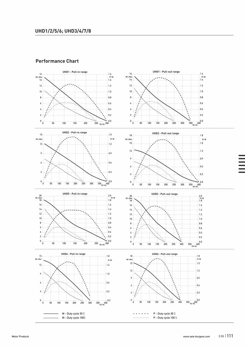
www.saia-burgess.comMotor Products | 111
UHD1/2/5/6; UHD3/4/7/8
Performance Chart
UHD1 - Pull-in range
0
2
4
6
8
10
12
14
16
0 50 100 150 200 250 300fS/ Hz
M/ cNm
0.0
0.2
0.4
0.6
0.8
1.0
1.2
1.4
1.6P/ W
UHD1 - Pull-out range
0
2
4
6
8
10
12
14
16
0 50 100 150 200 250 300 350 400fS/ Hz
M/ cNm
0.0
0.2
0.4
0.6
0.8
1.0
1.2
1.4
1.6P/ W
UHD2 - Pull-in range
0
3
6
9
12
15
0 50 100 150 200 250 300 350 400fS/ Hz
M/ cNm
0.0
0.3
0.6
0.9
1.2
1.5
P/ W
UHD2 - Pull-out range
0
3
6
9
12
15
18
0 50 100 150 200 250 300 350 400fS/ Hz
M/ cNm
0.0
0.3
0.6
0.9
1.2
1.5
1.8
P/ W
UHD5 - Pull-in range
0
2
4
6
8
10
12
14
16
18
20
0 50 100 150 200 250 300fS/ Hz
M/ cNm
0.0
0.2
0.4
0.6
0.8
1.0
1.2
1.4
1.6
1.8
2.0P/ W
UHD5 - Pull-out range
0
2
4
6
8
10
12
14
16
18
20
0 50 100 150 200 250 300 350 400fS/ Hz
M/ cNm
0.0
0.2
0.4
0.6
0.8
1.0
1.2
1.4
1.6
1.8
2.0P/ W
UHD6 - Pull-in range
0
3
6
9
12
15
0 50 100 150 200 250 300 350 400fS/ Hz
M/ cNm
-0.2
0.2
0.6
1.0
1.4
1.8
P/ W
UHD6 - Pull-out range
0
3
6
9
12
15
18
0 50 100 150 200 250 300 350 400fS/ Hz
M/ cNm
0.0
0.3
0.6
0.9
1.2
1.5
1.8P/ W
M - Duty cycle 30 % P - Duty cycle 30 %M - Duty cycle 100% P - Duty cycle 100 %
110

www.saia-burgess.com Motor Products112 |
UHD1/2/5/6; UHD3/4/7/8
Technical Data UHD3/4/7/8
bipolar (UHD3/7) Rated voltage UN V 12 24 48
Resistance per winding R20 20 108 460
Holding torque cNm 37,5 (UHD3); 45,5 (UHD7)
Detent torque MS cNm 3,4 (UHD3/4); 5,3 (UHD7/8)
Rotor inertia JR gcm2 135 (UHD3/4); 141 (UHD7/8)
unipolar (UHD4/8) Rated voltage UN V 6 12 24
Resistance per winding R20 6,75 28,5 120
Holding torque cNm 27,5 (UHD4); 33,5 (UHD8)
Detent torque MS cNm 3,4 (UHD3/4); 5,3 (UHD7/8)
Rotor inertia JR gcm2 135 (UHD3/4); 141 (UHD7/8)
Steps per revolution 48
Duty cycle 100%
Winding temperature Tmax 130° C
Direction of rotation reversible
Dimensions
113
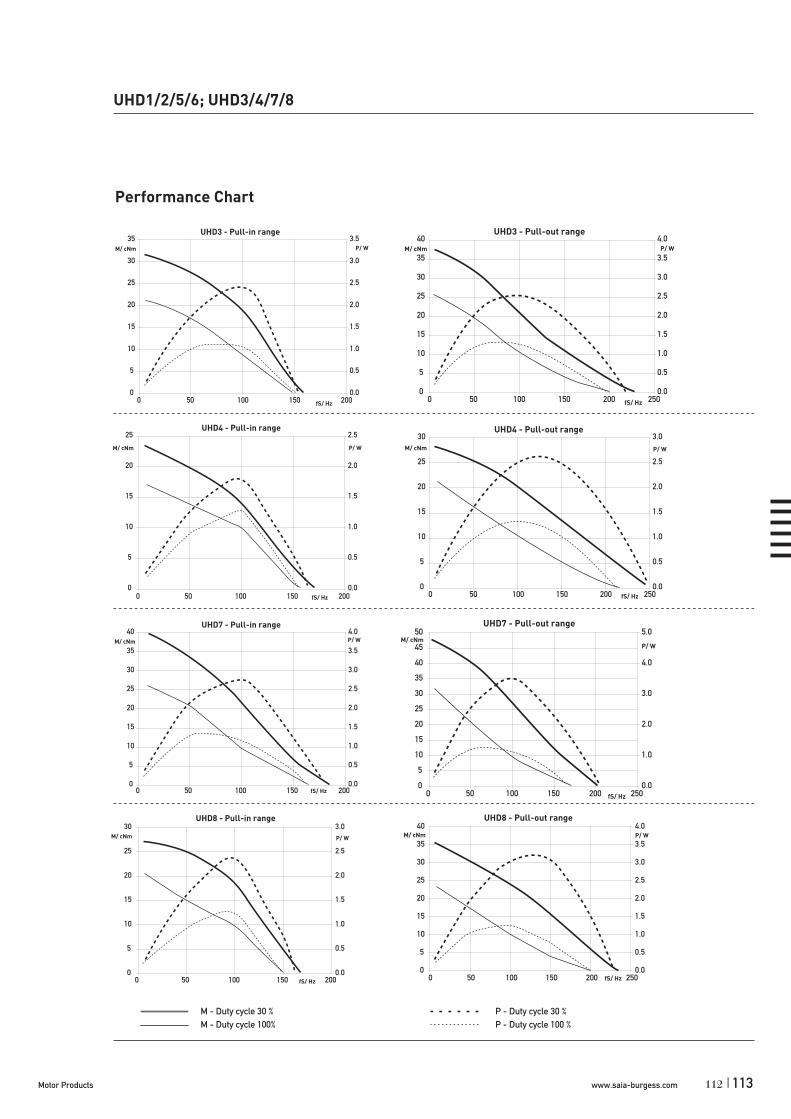
www.saia-burgess.comMotor Products | 113
UHD1/2/5/6; UHD3/4/7/8
Performance Chart
0
5
10
15
20
25
30
35
0 50 100 150 200fS/ Hz
M/ cNm
0.0
0.5
1.0
1.5
2.0
2.5
3.0
3.5P/ W
UHD3 - Pull-in range UHD3 - Pull-out range
0
5
10
15
20
25
30
35
40
0 50 100 150 200 250fS/ Hz
M/ cNm
0.0
0.5
1.0
1.5
2.0
2.5
3.0
3.5
4.0P/ W
UHD4 - Pull-in range
0
5
10
15
20
25
0 50 100 150 200fS/ Hz
M/ cNm
0.0
0.5
1.0
1.5
2.0
2.5
P/ W
UHD4 - Pull-out range
0
5
10
15
20
25
30
0 50 100 150 200 250fS/ Hz
M/ cNm
0.0
0.5
1.0
1.5
2.0
2.5
3.0P/ W
UHD7 - Pull-in range
0
5
10
15
20
25
30
35
40
0 50 100 150 200fS/ Hz
M/ cNm
0.0
0.5
1.0
1.5
2.0
2.5
3.0
3.5
4.0P/ W
UHD7 - Pull-out range
0
5
10
15
20
25
30
35
40
45
50
0 50 100 150 200 250fS/ Hz
M/ cNm
0.0
1.0
2.0
3.0
4.0
5.0
P/ W
0
5
10
15
20
25
30
0 50 100 150 200fS/ Hz
M/ cNm
0.0
0.5
1.0
1.5
2.0
2.5
3.0P/ W
UHD8 - Pull-in range
20
25
30
35
40
0 50 100 150 200 250fS/ Hz
M/ cNm
2.0
2.5
3.0
3.5
4.0P/ W
UHD8 - Pull-out range
0
5
10
15
0.0
0.5
1.0
1.5
M - Duty cycle 30 % P - Duty cycle 30 %M - Duty cycle 100% P - Duty cycle 100 %
112

www.saia-burgess.com Motor Products114 |
UPStepper Motors
Rotational
UP (ST6443; ST6444)
Dimensions (mm)
Step angle (°)
Holding torque (cNm)
Detent torque (cNm)
Winding
Gear combination
64 x 43
7,5/11,25 (ST6443); 11,25 (ST6444)
30–35 (ST6443); 45 (ST6444)
2–2,5 (ST6443); 7 (ST6444)
bipolar
UGO/UGP (STG60/61), UGR (STG200), UGS (V250)
Standard Data
Climatic class wide-spread according to DIN IEC 60721-2-1Ambient temperature operation °C -15 ... +40Ambient temperature storage °C -20 ... +100Thermal resistance at f=0 Rtherm 29 K/WThermal class B (ST6443); A (ST6444) according to DIN EN 60085Approval standardMounting any positionElectrical connection cableProtection IP 40 according to DIN EN 60529Weight 500 g (ST6443); 550 g (ST6444)Rotor stalling motor can be stopped when voltage is applied, without being overheatedBearings Sintered bronze, self- lubricating
Stepper Motor ST6443 / ST6444 7,5° 3,7
7,5° (ST6443)11,25° (ST6443 / ST6444)
3,7
Type
Step angle
Resistance
Order Reference
115

www.saia-burgess.comMotor Products | 115
UP (ST6443; ST6444)
Technical Data
bipolar (ST6443) Rated voltage UN V 4,5 4,5Resistance per winding R20 3,7Step angle ° 7,5 11,25Holding torque MH cNm 35 30Detent torque Ms cNm 2,5 2Rotor inertia JR gcm2 85
Steps per revolution 48 32Winding temperature increase K 90Current per winding A 1,25Inductance per winding mH 10 9,5Power consumption W 11,5Driver mode Chopper drive
bipolar (ST6444) Rated voltage UN V 4,5Resistance per winding R20 3,7Step angle ° 11,25Holding torque MH cNm 45Detent torque Ms cNm 7Rotor inertia JR gcm2 180
Steps per revolution 32Winding temperature increase K 90Current per winding A 1,25Inductance per winding mH 8Power consumption W 11,5Driver mode Chopper drive
Circuit diagram Motor connections - bipolar
A
B
A
A1yellow
A2blue
B1red
B2grey
A1A2
B1B2
B
clockwise rotation
114

www.saia-burgess.com Motor Products116 |
Performance Chart (chopper driver)
ST6443 UPD1 (ST6443/7,5/1) UPJ1 (ST 6443/11,25/1)
M/cNm M/cNm
fs/Hz fs/Hz
ST6444
Dimensions
Standard - wire length: 150 mmGeneral tolerances acc. to DIN ISO 2768-mk
M/cNm
fs/Hz
UPJ5 (ST 6444/11,25)
UP (ST6443; ST6444)
117
*
* on request 14h9
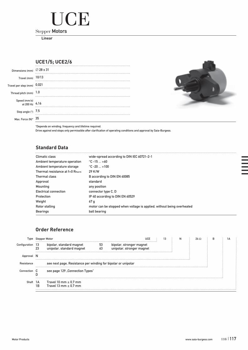
www.saia-burgess.comMotor Products | 117
Stepper Motor UCE 13 N 24 B 1A
13 bipolar, standard magnet 53 bipolar, stronger magnet23 unipolar, standard magnet 63 unipolar, stronger magnet
N
see next page, Resistance per winding for bipolar or unipolar
C see page 129 „Connection Types“D
1A Travel 10 mm ± 0,7 mm1B Travel 13 mm ± 0,7 mm
UCE1/5; UCE2/6
Dimensions (mm)
Travel (mm)
Travel per step (mm)
Thread pitch (mm)
Speed (mm/s)at 200 Hz
Step angle (°)
Max. Force (N)*
UCEStepper Motors
Linear
28 x 31
10/13
0,021
1,0
4,16
7,5
35
*Depends on winding, frequency and lifetime required. Drive against end stops only permissible after clarification of operating conditions and approval by Saia-Burgess.
Standard Data
Climatic class wide-spread according to DIN IEC 60721-2-1Ambient temperature operation °C -15 ... +60Ambient temperature storage °C -20 ... +100Thermal resistance at f=0 Rtherm 29 K/WThermal class B according to DIN EN 60085Approval standardMounting any positionElectrical connection connector type C, DProtection IP 40 according to DIN EN 60529Weight 67 g Rotor stalling motor can be stopped when voltage is applied, without being overheatedBearings ball bearing
Type
Configuration
Approval
Resistance
Connection
Shaft
Order Reference
116

www.saia-burgess.com Motor Products118 |
UCE1/5; UCE2/6
Technical Data
bipolar type UCE1 UCE1 UCE5 UCE5Operating frequency Hz 100 200 100 200max. Push/Pull force * 30% duty cycle N 49 42 50 50
100% duty cycle N 42 28 49 39
unipolar type UCE2 UCE2 UCE6 UCE6Operating frequency Hz 100 200 100 200max. Push/Pull force * 30% duty cycle N 35 28 49 39
100% duty cycle N 21 17 29 23
Rated voltage UN: V 6 12 24Resistance per winding R20 24 90 380Steps per mm 48Duty cycle 100 %Winding temperature Tmax °C 130Linear travel max. mm 10/13Axial play at ± 20 N force mm < 0,25
* measured at 23 °C, lifetime depends on load characteristics and ambient conditions
Circuit diagram bipolar
unipolar
Pull (in)
Push (out)
Pull (in)
Push (out)
119

www.saia-burgess.comMotor Products | 119
Version with connector D, 10 mm travelDimensions
UCE1/5; UCE2/6
Trave l
118

www.saia-burgess.com Motor Products120 |
Stepper Motor UCL 13 N 24 B 1A
13 bipolar, standard magnet 53 bipolar, stronger magnet23 unipolar, standard magnet 63 unipolar, stronger magnet
N
see next page, Resistance per winding for bipolar or unipolar
C see page 129 „Connection Types“D
1A Travel 10 mm ± 0,7 mm1B Travel 13 mm ± 0,7 mm
UCL1/5; UCL2/6
Dimensions (mm)
Travel (mm)
Travel per step (mm)
Thread pitch (mm)
Speed (mm/s)at 200 Hz
Step angle (°)
Max. Force (N)*
UCLStepper Motors
Linear
28 x 31
10/13
0,041
1,0
8,33
15
35
*Depends on winding, frequency and lifetime required. Drive against end stops only permissible after clarification of operating conditions and approval by Saia-Burgess.
Standard Data
Climatic class wide-spread according to DIN IEC 60721-2-1Ambient temperature operation °C -15 ... +60Ambient temperature storage °C -20 ... +100Thermal resistance at f=0 Rtherm 29 K/WThermal class B according to DIN EN 60085Approval standardMounting any positionElectrical connection connector type C, DProtection IP 40 according to DIN EN 60529Weight 67 g Rotor stalling motor can be stopped when voltage is applied, without being overheatedBearings ball bearing
Type
Configuration
Approval
Resistance
Connection
Shaft
Order Reference
121
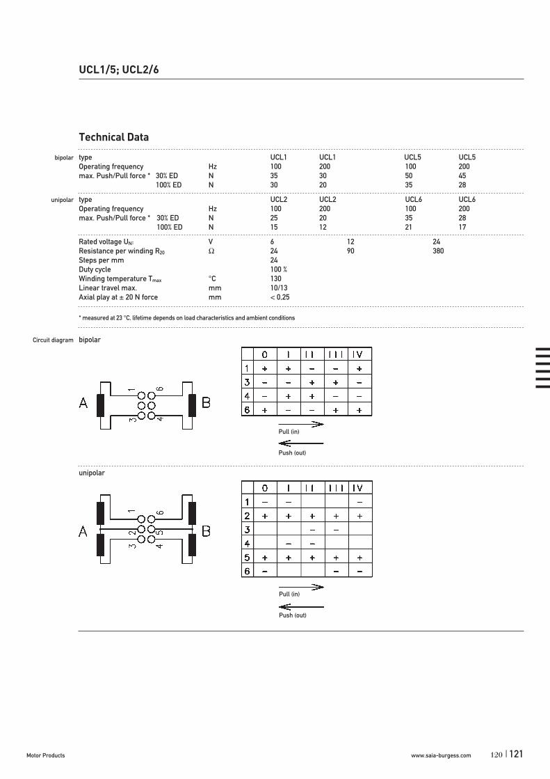
www.saia-burgess.comMotor Products | 121
UCL1/5; UCL2/6
Technical Data
bipolar type UCL1 UCL1 UCL5 UCL5Operating frequency Hz 100 200 100 200max. Push/Pull force * 30% ED N 35 30 50 45
100% ED N 30 20 35 28
unipolar type UCL2 UCL2 UCL6 UCL6Operating frequency Hz 100 200 100 200max. Push/Pull force * 30% ED N 25 20 35 28
100% ED N 15 12 21 17
Rated voltage UN: V 6 12 24Resistance per winding R20 24 90 380Steps per mm 24Duty cycle 100 %Winding temperature Tmax °C 130Linear travel max. mm 10/13Axial play at ± 20 N force mm < 0,25
* measured at 23 °C, lifetime depends on load characteristics and ambient conditions
Circuit diagram bipolar
unipolar
Pull (in)
Push (out)
Pull (in)
Push (out)
120
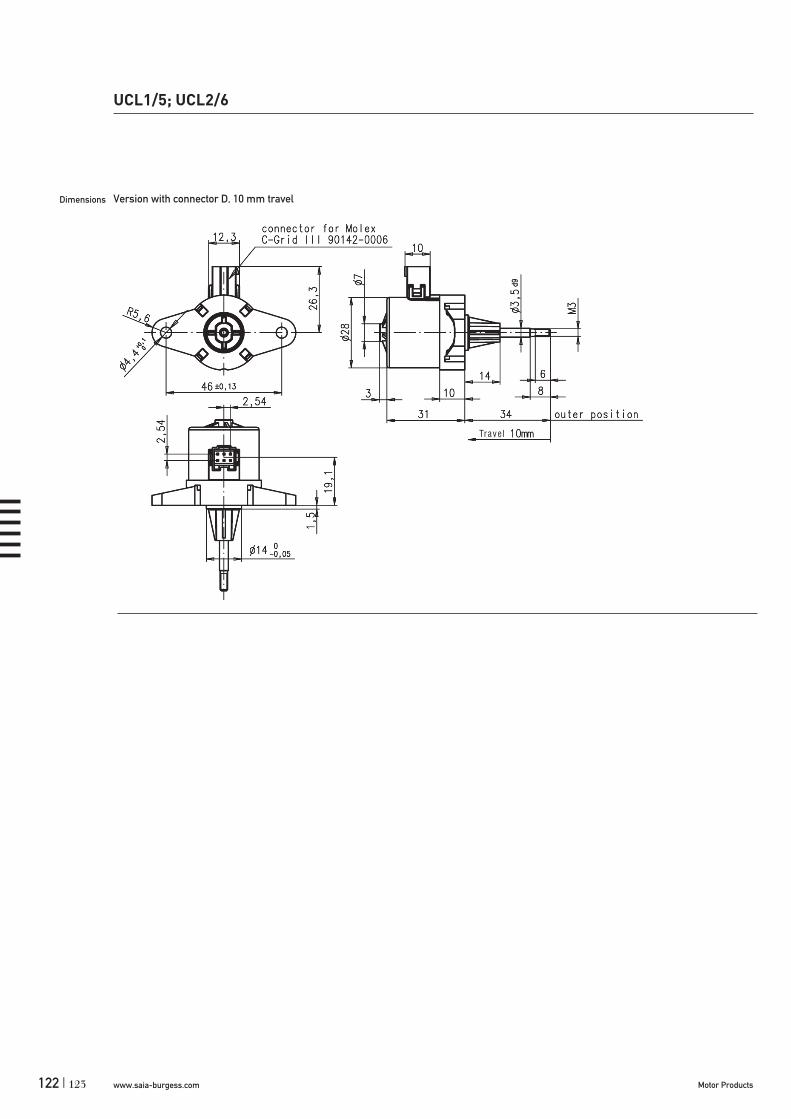
www.saia-burgess.com Motor Products122 |
UCL1/5; UCL2/6
Version with connector D, 10 mm travelDimensions
Trave l
123

www.saia-burgess.comMotor Products | 123
UBLStepper Motors
Linear
UBL1/2
Dimensions (mm)
Travel (mm)
Travel per step (mm)
Thread pitch (mm)
Speed (mm/s)at 200 Hz
Step angle (°)
Max. Force (N)*
Lifetime
36 x 36
8; 13; 56 ± 0,7
0,041
0,8
8.33
15
35 (for special winding, lower lifetime)
on request
*Depends on winding, frequency and lifetime required. Drive against end stops only permissible after clarification of operating conditions and approval by Saia-Burgess.
Standard Data
Climatic class wide-spread according to DIN IEC 60721-2-1
Ambient temperature operation °C -15...+60Ambient temperature storage °C -20...+100Thermal resistance at f=0 Rtherm 27 K/W
Thermal class B according to DIN EN 60085
Approval standard
Mounting any position
Electrical connection jack connector
Protection IP 40 according to DIN EN 60529
Weight 90 g
Rotor stalling motor can be stopped when voltage is applied, without being overheated
Bearings ball bearing, for live lubricated
Electric strength according to DIN EN 60034-1/DIN EN 60335-1
Type
Configuration
Approval
Resistance
Connection
Shaft
Stepper Motor UBL 13 N 100 B 3C
13 bipolar23 unipolar
N Approval Standard
See next page Resistance per winding for bipolar or unipolar.
Jack connector 6 pin (other on request)
3C Travel 8 mm ± 0,7 mm / Tr. 3,7 x 1 (other on request)
Order Reference
122

www.saia-burgess.com Motor Products124 |
Technical Data
bipolar (UBL1) Rated voltage UN V 6 12 24
Resistance per winding R20 18,5 100 460
unipolar (UBL2) Rated voltage UN V 6 12 24
Resistance per winding R20 28 120 500
Steps per revolution 24
Steps per mm 30/24
Winding temperature Tmax 180° C
Duty cycle 100%
Linear travel max. 8; 13; 56 ± 0,7
Axial play at ± 20 N force < 0,25 mm
Axial force at 200 Hz FA 10 N
Dimensions
UBL1/2
1 connector B AMP 829 836-12 connector C AMP 963 004-13 connector D for Molex C-Grid-III 90142-0006
125

www.saia-burgess.comMotor Products | 125
Stepper Motor LA5021ST 7 0,031 mm 50 mm
7
0,031 mm0,047 mm0,063 mm
50 mm
UO Linear actuator (LA5021ST)
Dimensions (mm)
Travel (mm)
Travel per step (mm)
Thread pitch (mm)
Speed (mm/s)at 200 Hz
Step angle (°)
Max. Force (N)*
UO Linear actuatorStepper Motors
Linear
50 x 76
45–50
0,031/0,047/0,063
1,5/1,5/1,5
6,25/9,37/12,5
7,5/11,25/15
45–50
*Depends on winding, frequency and lifetime required. Drive against end stops only permissible after clarification of operating conditions and approval by Saia-Burgess.
Standard Data
Climatic class wide-spread according to DIN IEC 60721-2-1Ambient temperature operation °C -15 ... +40Ambient temperature storage °C -20 ... +105Thermal resistance at f=0 Rtherm K/W 20Thermal class A according to DIN EN 60085Approval standardMounting any positionElectrical connection cableProtection IP 40 according to DIN EN 60529Weight ~220 g Rotor stalling motor can be stopped when voltage is applied, without being overheatedBearings ball bearing
Type
Resistance
Travel per step
Travel
Order Reference
124

www.saia-burgess.com Motor Products126 |
UO Linear actuator (LA5021ST)
Technical Data
bipolar Rated voltage UN: V 4 (Chopper drive)Resistance per winding R20 7Step angle ° 7,5 11,25 15Travel per step mm 0,031 0,047 0,063Steps per mm 32 21 16Winding temperature Tmax °C 130Duty cycle 100%Linear travel max. mm 50Axial play at 20 N force mm <0,25
Dimensions
Push movement
Standard - wire length: 100+20 mm/6±1 stripped
127

www.saia-burgess.comMotor Products | 127
Stepper Motor SP5022ST 7 0,031 mm 68 mm
7
0,031 mm0,047 mm0,063 mm
68 mm130 mm
UO Spindle actuator (SP5022ST)
Dimensions (mm)
Travel (mm)
Travel per step (mm)
Thread pitch (mm)
Speed (mm/s)at 200 Hz
Step angle (°)
Max. Force (N)*
UO Spindle actuatorStepper Motors
Linear
50 x 27
68–130
0,031/0,047/0,063
1,5/1,5/1,5
6,25/9,37/12,5
7,5/11,25/15
50–70
*Depends on winding, frequency and lifetime required. Drive against end stops only permissible after clarification of operating conditions and approval by Saia-Burgess.
Standard Data
Climatic class wide-spread according to DIN IEC 60721-2-1Ambient temperature operation °C -15 ... +40Ambient temperature storage °C -20 ... +105Thermal resistance at f=0 Rtherm K/W 20Thermal class A according to DIN EN 60085Approval standardMounting any positionElectrical connection cableProtection IP 40 according to DIN EN 60529Weight ~220 g Rotor stalling motor can be stopped when voltage is applied, without being overheatedBearings ball bearing
Type
Resistance
Travel per step
Travel
Order Reference
126

www.saia-burgess.com Motor Products128 |
UO Spindle actuator (SP5022ST)
Technical Data
bipolar Rated voltage UN: V 4 (Chopper drive)Resistance per winding R20 7Step angle ° 7,5 11,25 15Travel per step mm 0,031 0,047 0,063Steps per mm 32 21 16Winding temperature Tmax °C 130Travel mm ~68/+130Positioning accuacy (incl. axial play) mm ± 0,15Static axial force N max. 50Self-locking by spindle/nut system yesDrive not stall-proofAnti-rotation guidance of spindle external required
Dimensions Version with Travel 68 mm 130 mm
Push movement
Standard - wire length: 100+20 mm/6±1 stripped
129

www.saia-burgess.comMotor Products | 129
Connection Typesfor UC-Series
Lead wire Connection N
(view to drive side) (view to drive side)
up to 48 Vfor rotary motors different lead colours for 110 V (230 V)(bipolar, synchronous in parallel circuit) for rotary synchronous motors in series circuit
Connector Connector C Connector D
for Tyco Tyco Modu IV 0-1740209-6 for Molex C-Grid III 90142-006
(view to drive side) (view to drive side)
up to 48 V up to 48 Vfor linear motors for rotary and linear motors(bipolar, unipolar, synchronous) (bipolar, unipolar, synchronous)
128

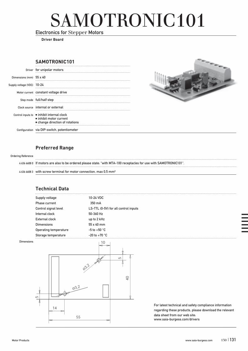
www.saia-burgess.comMotor Products | 131
SAMOTRONIC101Electronics for Stepper Motors
Driver Board
SAMOTRONIC101
Driver
Dimensions (mm)
Supply voltage (VDC)
Motor current
Step mode
Clock source
Control inputs to
Configuration
for unipolar motors
55 x 40
10-24
constant voltage drive
full/half step
internal or external
inhibit internal clockinhibit motor currentchange direction of rotations
via DIP-switch, potentiometer
Preferred Range
Ordering Reference
4 636 6608 0 If motors are also to be ordered please state: “with MTA-100 receptacles for use with SAMOTRONIC101“.
4 636 6608 3 with screw terminal for motor connection, max 0,5 mm2
Technical Data
Supply voltage 10-24 VDC
Phase current 350 mA
Control signal level LS-TTL (0-5V) for all control inputs
Internal clock 50-360 Hz
External clock up to 2 kHz
Dimensions 55 x 40 mm
Operating temperature -5 to +50 °C
Storage temperature -20 to +70 °C
Dimensions
130
For latest technical and safety compliance information regarding these products, please download the relevant data sheet from our web site:www.saia-burgess.com/drivers

Technical Data
Supply voltage 10-24 (42)VDC
Phase current 71-500 mA, on request max. 735mA/ph
Chopper frequency typ. 20kHz
Control signal level LS-TTL (0-5V) for all control inputs
Internal clock 50-1325 Hz
External clock up to 2 kHz
Dimensions 84 x 54 mm
Operating temperature -20 to +60 °C
Storage temperature -20 to +80 °C
Dimensions
SAMOTRONIC102Electronics for Stepper Motors
Driver Board with microcontroller for customised control features
SAMOTRONIC102
Driver
Dimensions (mm)
Supply voltage (VDC)
Motor current
Step mode
Clock source
Control inputs to
Configuration
Test pins
for bipolar motors
84 x 54
standard version 10 DC–24 enhanced version 10 DC–42
constant current drive (chopper controlled) adjustable via potentiometer
full/half step
internal or external
inhibit internal clockinhibit motor currentchange direction of rotations
via DIP-switch, potentiometer
motor currentstep frequency
Preferred Range
Ordering Reference
4 636 6733 0 10-24VDC supply voltage (standard version)
4 636 6733 3 10-42VDC supply voltage (enhanced version)
If motors are also to be ordered please state: “with MTA-100 receptacles for use with SAMOTRONIC102”.
133
For latest technical and safety compliance information regarding these products, please download the relevant data sheet from our web site:www.saia-burgess.com/drivers
www.saia-burgess.com Motor Products132 |

Evaluation-Kit 2
Driver
Dimensions (mm)
Supply voltage (VDC)(VAC)
Motor current
Step mode
Clock source
Control inputs to
Configuration
Evaluation-Kit 2Electronics for Stepper Motors
Driver Board
for unipolar and bipolar motors
metal case 164 x 130 x 45
3–4824
constant voltage drive and constant current drive (chopper controlled)
full/half/micro step
internal, programmable
3 digital inputs4 signal outputs1 analog input 0...10 VDC relay contact
RS 232, USB
Technical Data
Supply voltage 10-48 VDC/24 VAC
Phase current up to 2,3 A
Step modes 11 (full, half, wave ... microstep)
Max. step frequency 10 kHz
PLC max. 256 steps, 65536 loops
Operating temperature 0 ... +55 °C
Storage temperature -20 to +80 °C
Test the Stepconfreeware without hardware in a
special demo mode
(www.saia-burgess.com/evaluationkit2).
For further information please contact your
Saia-Burgess sales company
or see our website www.saia-burgess.com.
4 717 4898 0
Power supply (on request)
Order Reference
132www.saia-burgess.comMotor Products | 133

www.saia-burgess.com Motor Products134 |
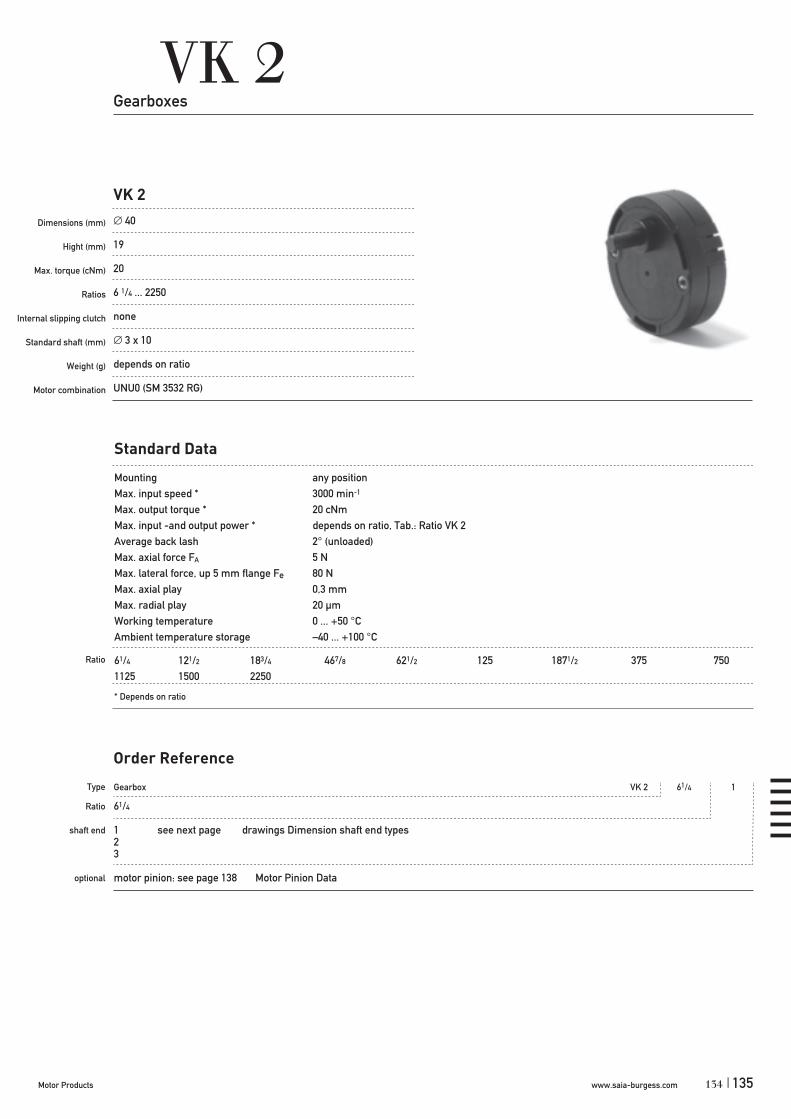
www.saia-burgess.comMotor Products | 135
Gearbox VK 2 61/4 1
61/4
1 see next page drawings Dimension shaft end types 23
motor pinion: see page 138 Motor Pinion Data
VK 2
Dimensions (mm)
Hight (mm)
Max. torque (cNm)
Ratios
Internal slipping clutch
Standard shaft (mm)
Weight (g)
Motor combination
VK 2Gearboxes
40
19
20
6 1/4 ... 2250
none
3 x 10
depends on ratio
UNU0 (SM 3532 RG)
Standard Data
Mounting any positionMax. input speed * 3000 min-1
Max. output torque * 20 cNmMax. input -and output power * depends on ratio, Tab.: Ratio VK 2Average back lash 2° (unloaded)Max. axial force FA 5 NMax. lateral force, up 5 mm flange Fe 80 NMax. axial play 0,3 mmMax. radial play 20 μmWorking temperature 0 ... +50 °CAmbient temperature storage –40 ... +100 °C
61/4 121/2 183/4 467/8 621/2 125 1871/2 375 7501125 1500 2250
* Depends on ratio
Type
Ratio
shaft end
optional
Order Reference
Ratio
134

www.saia-burgess.com Motor Products136 |
VK 2
Technical Data
Ratio Stages * pinion type Weight Input power ** Outout Power max. (W) max. (W)
61/4 2 0,8 1 35 0,7 0,57121/2 3 0,73 2 40 0,7 0,51183/4 3 0,73 4 40 0,7 0,51467/8 4 0,65 4 45 0,7 0,46621/2 4 0,65 3 45 0,7 0,46125 5 0,59 2 50 0,7 0,411871/2 5 0,59 4 50 0,57 0,34375 6 0,53 4 55 0,32 0,17750 6 0,53 4 55 0,16 0,081125 7 0,48 4 60 0,13 0,061500 7 0,48 4 60 0,08 0,042250 7 0,48 4 60 0,06 0,03
* Direction of rotaton of output- and motor-shaft at 2,4 and 6 stages - same 3 and 5 stages - opposite
** In combination with max. input speed / max. input torqueTechnical Data valid for a working temperature 0 °C ... +50 °C
Dimensions Shaft end types VK 2
137

www.saia-burgess.comMotor Products | 137
VK 2
Dimensions
136

www.saia-burgess.com Motor Products138 |
VK 2
pinion position Dimension „a“ „b“
2 gear stages 7,6–0,2 153–7 gear stages 4,8–0,2 15
Motor Pinion Data VK 2
pinion type d h D module no. of teeth Order Reference
1 1,5S8 3 6,09 0,35 14 022-100-006-100 2,0S8 3 6,09 0,35 14 022-100-006-110 2,3S8 3 6,09 0,35 14 022-100-006-120 2,5S8 3 0,96 0,35 14 022-100-006-130
2 1,5S8 3 6,0 0,29 18 022-100-006-140 2,0S8 3 6,0 0,29 18 022-100-006-150 2,3S8 3 6,0 0,29 18 022-100-006-160 2,5S8 3 6,0 0,29 18 022-100-006-170
3 1,5S8 3 5,44 0,32 14 022-100-006-180 2,0S8 3 5,44 0,32 14 022-100-006-190 2,3S8 3 5,44 0,32 14 022-100-006-200 2,5S8 3 5,44 0,32 14 022-100-006-210
4 1,5S8 3 4,86 0,3 13 022-100-006-220 2,0S8 3 4,86 0,3 13 022-100-006-230 2,3S8 3 4,86 0,3 13 022-100-006-240 2,5S8 3 4,86 0,3 13 022-100-006-250
139
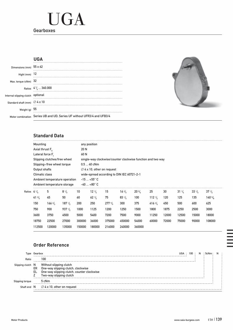
www.saia-burgess.comMotor Products | 139
UGAGearboxes
UGA
Dimensions (mm)
Hight (mm)
Max. torque (cNm)
Ratios
Internal slipping clutch
Standard shaft (mm)
Weight (g)
Motor combination
55 x 62
12
32
4 1/6 ... 360.000
optional
4 x 10
55
Series UB and UD; Series UF without UFR3/4 and UFB3/4
Standard Data
Mounting any position
Axial thrust FA 20 N
Lateral force FR
60 N
Slipping clutches/free wheel single-way clockwise/counter clockwise function and two way
Slipping-/free wheel torque 0,5 ... 40 cNm
Output shafts 4 x 10, other on request
Climatic class wide-spread according to DIN IEC 60721-2-1
Ambient temperature operation -15 ... +55° C
Ambient temperature storage -40 ... +80° C
Ratios 4 1/6 5 8 1/3 10 12 1/2 15 16 2/3 20 5/6 25 30 31 1/4 33 1/3 37 1/2
41 2/3 45 50 60 62 1/2 75 83 1/3 100 112 1/2 120 125 135 140 5/8
150 166 2/3 187 1/2 200 250 277 7/9 300 375 416 2/3 450 500 600 625
750 900 937 1/2 1000 1125 1200 1250 1500 1800 1875 2250 2500 3000
3600 3750 4500 5000 5400 7200 7500 9000 11250 12000 12500 15000 18000
18750 22500 27000 300000 36000 375000 450000 54000 60000 72000 75000 90000 108000
112500 120000 135000 150000 180000 216000 240000 360000
Type
Ratio
Slipping clutch
Slipping torque
Shaft end
Gearbox UGA 100 N 5cNm N
100
N Without slipping clutchER One-way slipping clutch, clockwiseEL One-way slipping clutch, counter clockwiseZ Two-way slipping clutch
5 cNm
N 4 x 10, other on request
Order Reference
138

www.saia-burgess.com Motor Products140 |
Dimensions
UGA
Slipping clutches
max. torque available at output shaft (cNm) free wheel- / clutch torque (cNm)
32 0,5 ... 1
32 2 ... 40 (counter clockwise or clockwise direction possible)
1,5 ... 10 2 ... 36
Roller-type free wheel
Single-wayslipping clutches
Two-wayslipping clutches
Torque / ratio / life graph
motor torque with consideration for gear efficency
In combination with motors n=250 rpm, continuous operation and Tambient 10000 h 1000 h
In combination with motors n=500 rpm, continuous operation and Tambient 10000 h 1000 h
±0,2
141

www.saia-burgess.comMotor Products | 141
UGDGearboxes
4 1/6 5 8 1/3 10 12 1/2 15 16 2/3 20 5/6 25 30 33 1/3 40 41 2/3
45 50 60 62 1/2 83 1/3 100 120 125 150 166 2/3 200 250 300
375 500 600 625 750 900 1000 1200 1500 1800 2000 2400 2500
3000 3600 3750 4500 5000 6000 7500 9000 10000 15000 18000 21600 22500
30000 36000 45000 54000 60000 72000 90000 108000 112500 120000 180000 216000 225000
270000 300000 360000 432000 450000 720000 864000 1800000 5040000 6048000
Standard Data
Mounting any position
Axial thrust FA 10 N
Lateral force FR 50 N
Slipping clutches/free wheel single-way clockwise/counter clockwise function and two way
Slipping-/free wheel torque 1 ... 40 cNm
Output shafts 4 x 10, other on request
Climatic class wide-spread according to DIN IEC 60721-2-1
Ambient temperature operation °C -15 ... +55
Ambient temperature storage °C -40 ... +80
Ratios
Type
Ratio
Slipping clutch
Slipping torque
Shaft end
Gearbox UGD 100 N 5cNm N
100
N Without slipping clutchER One-way slipping clutch, clockwiseEL One-way slipping clutch, counter clockwiseZ Two-way slipping clutch
5 cNm
N 4 x 10, other on request
Order Reference
UGD
Dimensions (mm)
Hight (mm)
Max. torque (cNm)
Ratios
Internal slipping clutch
Standard shaft (mm)
Weight (g)
Motor combination
55 x 65,6
13
32
4 1/6 ... 6.048.000
optional
4 x 10
35
Series UB and UD; Series UF without UFR3/4 and UFB3/4
140
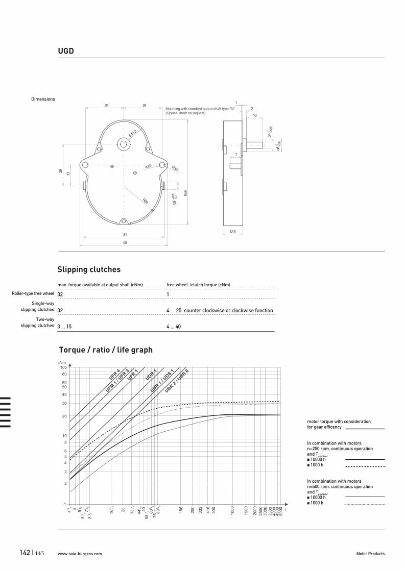
www.saia-burgess.com Motor Products142 |
Slipping clutches
max. torque available at output shaft (cNm) free wheel-/clutch torque (cNm)
32 1
32 4 ... 25 counter clockwise or clockwise function
3 ... 15 4 ... 40
UGD
Dimensions
1
2
3
4
5
6
10
8
20
30
40
5060
80
100
4/
1
6 5
5/
5
66
/2
3
7/
1
2
8/
1
3 16
/2
3
25
33
/1
3
44
/2
3
50
58
/1
3 66
/2
3
75 8
3/
1
3
16
6
25
0
33
3
416
50
0
10
00
15
00
20
00
25
00
30
00
35
00
40
00
45
00
50
00
cNm
i
UFR4
UFM1 / U
FR3
UFR1
UDR1
UBR1 / U
DS 1
UBR2 / U
BR6
Roller-type free wheel
Single-wayslipping clutches
Two-wayslipping clutches
Torque / ratio / life graph
motor torque with consideration for gear efficency
In combination with motors n=250 rpm, continuous operation and Tambient 10000 h 1000 h
In combination with motors n=500 rpm, continuous operation and Tambient 10000 h 1000 h
143

www.saia-burgess.comMotor Products | 143
Gearbox VK 4 61/4 1
61/4
1 see next page drawings Dimension shaft end types23
motor pinion: see page 146 Motor Pinion Data
VK 4
Dimensions (mm)
Hight (mm)
Max. torque (cNm)
Ratios
Internal slipping clutch
Standard shaft (mm)
Weight (g)
Motor combination
VK 4Gearboxes
52
20
40
6 1/4 ... 1875
none
3 x 10
depends on ratio
3532 RG, 5021–, 5022–, 5032 RG– series
Standard Data
Mounting any positionMax. input speed * 3000 min-1
Max. output torque * 40 cNmMax. input -and output power * depends on ratio, Tab.: Ratio VK 4Average back lash 2° (unloaded)Max. axial force FA 5 NMax. lateral force, up 5 mm flange Fe 80 NMax. axial play 0,3 mmMax. radial play 20 μmWorking temperature 0 ... +50 °CAmbient temperature storage –40 ... +100 °C
61/4 121/2 183/4 371/2 933/4 125 150 1871/2 375 750 1500 1875
* Depends on ratio
Type
Ratio
shaft end
optional
Order Reference
Ratio
142

www.saia-burgess.com Motor Products144 |
VK 4
Technical Data
Ratio Stages * pinion type Weight Input power ** Outout Power max. (W) max. (W)
61/4 2 0,81 1 45 1,7 1,4121/2 2 0,81 1 45 1,7 1,4183/4 3 0,73 1 50 1,7 1,2371/2 3 0,73 1 50 1,7 1,2933/4 4 0,65 1 55 1,7 1,1125 4 0,65 1 55 1,54 1150 4 0,65 1 55 1,29 0,841871/2 5 0,59 1 60 1,14 0,67375 5 0,59 1 60 0,58 0,34750 6 0,53 1 65 0,32 0,171500 6 0,53 1 65 0,15 0,081875 6 0,53 1 65 0,12 0,06
* Direction of rotaton of output- and motor-shaft at 2,4 and 6 stages - same 3 and 5 stages - opposite
** In combination with max. input speed / max. input torqueTechnical Data valid for a working temperature 0 °C ... +50 °C
Dimensions Shaft end types VK 4
145

www.saia-burgess.comMotor Products | 145
VK 4
Dimensions
144

www.saia-burgess.com Motor Products146 |
VK 4
pinion position Dimension „a“ „b“
2 gear stages 8,6–0,2 163–5 gear stages 5,9–0,2 166 gear stages 8,6–0,2 16
Motor Pinion Data VK 4
pinion type d h D module no. of teeth Order Reference
1 1,5S8 3,5 5,76 0,3 16 022-100-006-260 2,0S8 3,5 5,76 0,3 16 022-100-006-270 2,3S8 3,5 5,76 0,3 16 022-100-006-280 2,5S8 3,5 5,76 0,3 16 022-100-006-290 3,0S8 3,5 5,76 0,3 16 022-100-006-300
147

www.saia-burgess.comMotor Products | 147
UGMGearboxes
12 1/2 16 2/3 25 50 100 120 150 200 240 300 400 500 600
750 1000 1200 1500 4800
Standard Data
Mounting any position
Axial thrust FA 20 N
Lateral force FR 100 N
Output shafts 4 x 10, other on request
Climatic class wide-spread according to DIN IEC 60721-2-1
Ambient temperature operation °C -15 ... +60
Ambient temperature storage °C -40 ... +80
Ratios
Type
Ratio
Slipping clutch
Shaft end
Gearbox UGM 100 N N
100
N Without slipping clutch
N 4 x 10, other on request
Order Reference
UGM
Dimensions (mm)
Hight (mm)
Max. torque (cNm)
Ratios
Internal slipping clutch
Standard shaft (mm)
Weight (g)
Motor combination
51 x 65.2
15
100
12.5 ... 4800
none
4 x 10
45
Series UB and UD; Series UF without UFR3/4 and UFB3/4
146

www.saia-burgess.com Motor Products148 |
UGM
Dimensions
ø3,5
E1
E2
4,9 0,1
ø4h8
ø80 -0,05
2 +0,10
14,7 0,3
10 0,1
0,50,5
420,2
48
26 0,05
13
ø39
30
ø2,5
2
ø8+0,050
ø11
R3,5
R15,2
65,2 +0,50
51
48+0,30
10
1042,5
E22:1
ø2,2
1,28
E12:1
0,42,2
0,7ø2,5
JS12
ø2,9
+0,10
16,5
Mounting with standard shaft type "N"
(Special shaft on request)
149
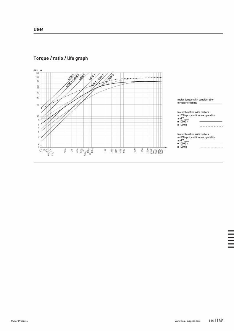
www.saia-burgess.comMotor Products | 149
UGM
1
2
3
4
5
6
10
8
20
30
40
5060
80
100
120
4/
1
6 5
5/
5
66
/2
3
7/
1
2
8/
1
3 16
/2
3
25
33
/1
3
44
/2
3
50
58
/1
3 66
/2
3
75 8
3/
1
3
166
250
333
41
6
500
10
00
15
00
20
00
25
00
30
00
350
04
00
04
500
50
00
cNm
i
UFR4
UFM1 / U
FR3
UFR1
UDR 1
UBR1 / U
DS 1
UBR2 / U
BR6
Torque / ratio / life graph
motor torque with consideration for gear efficency
In combination with motors n=250 rpm, continuous operation and Tambient 10000 h 1000 h
In combination with motors n=500 rpm, continuous operation and Tambient 10000 h 1000 h
148

www.saia-burgess.com Motor Products150 |
UGBGearboxes
41 2/3 83 1/3 100 125 150 166 2/3 200 250 300 500 600 750 900
1000 1200 1500 1800 2000 2500 3000 3750 5000 6000 7500 12000 15000
18000 30000 36000 60000 120000 266666 2/3 288000 320000 345600
Standard Data
Mounting any position
Axial thrust FA 100 N
Lateral force FR 300 N
Slipping clutches/free wheel single-way clockwise/counter clockwise function and two way
Slipping-/free wheel torque 4 ... 175 cNm
Output shafts Ø 8 x 12, other on request
Climatic class wide-spread according to DIN IEC 60721-2-1
Ambient temperature operation °C -15 ... +55
Ambient temperature storage °C -40 ... +80
Ratios
Type
Ratio
Slipping clutch
Slipping torque
Shaft end
Gearbox UGB 100 N 5cNm N
100
N Without slipping clutchER One-way slipping clutch, clockwiseEL One-way slipping clutch, counter clockwiseZ Two-way slipping clutch
5 cNm
N 8 x 12, other on request
Order Reference
UGB
Dimensions (mm)
Hight (mm)
Max. torque (cNm)
Ratios
Internal slipping clutch
Standard shaft (mm)
Weight (g)
Motor combination
58 x 81
17
250
412/3 ... 345.600
optional
8 x 12
130
Series UB and UD; Series UF without UFR3/4 and UFB3/4
151
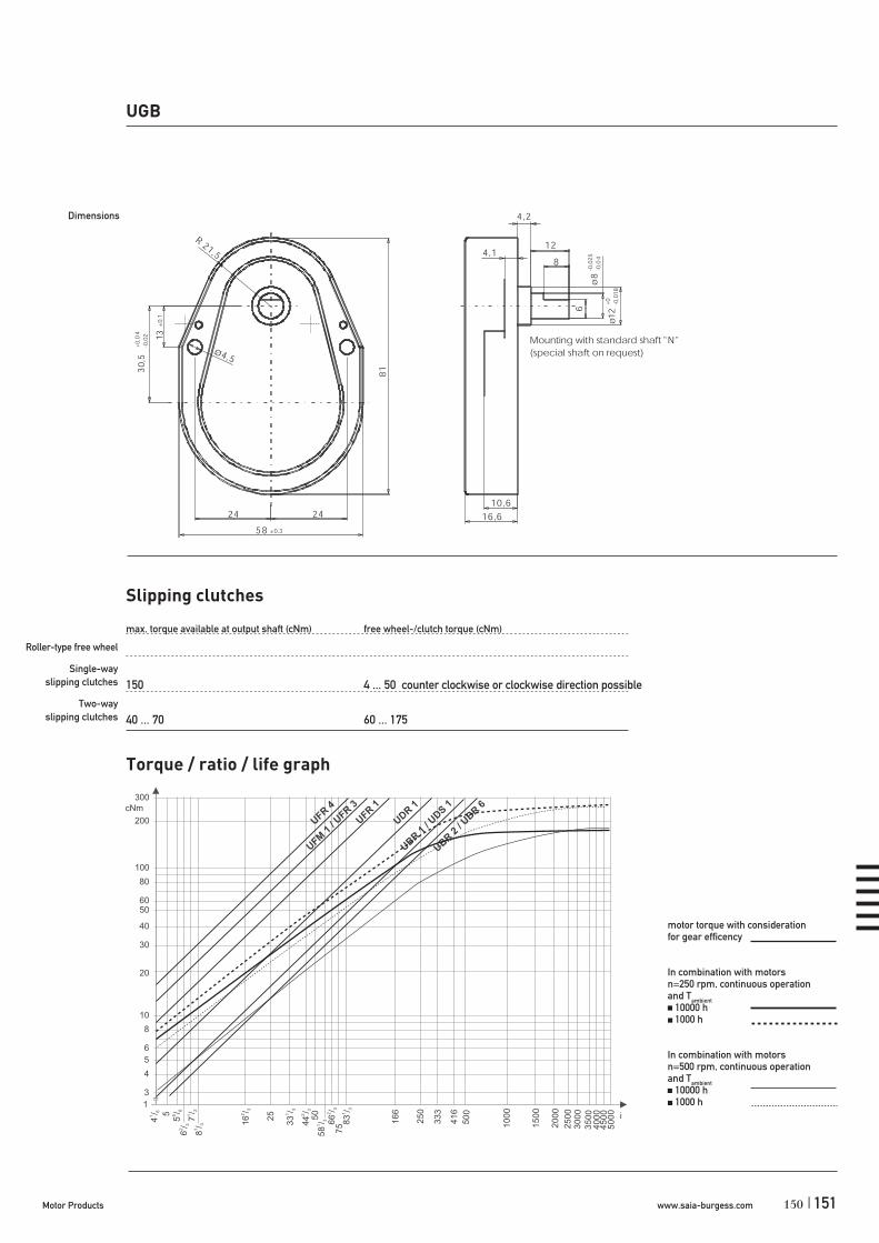
www.saia-burgess.comMotor Products | 151
UGB
Dimensions
1
3
4
5
6
10
8
20
30
40
5060
80
100
200
300
4/
1
6 5
5/
5
66
/2
3
7/
1
2
8/
1
3 16
/2
3
25
33
/1
3
44
/2
3
50
58
/1
3 66
/2
3
75 8
3/
1
3
166
25
0
33
3
41
6
50
0
100
0
15
00
20
00
25
00
30
00
35
00
400
04
50
05
00
0
cNm
i
UFR4
UFM1 / U
FR3
UFR1
UDR 1
UBR1 / U
DS 1
UBR2 / U
BR6
Slipping clutches
max. torque available at output shaft (cNm) free wheel-/clutch torque (cNm)
150 4 ... 50 counter clockwise or clockwise direction possible
40 ... 70 60 ... 175
Roller-type free wheel
Single-wayslipping clutches
Two-wayslipping clutches
Torque / ratio / life graph
motor torque with consideration for gear efficency
In combination with motors n=250 rpm, continuous operation and Tambient 10000 h 1000 h
In combination with motors n=500 rpm, continuous operation and Tambient 10000 h 1000 h
150
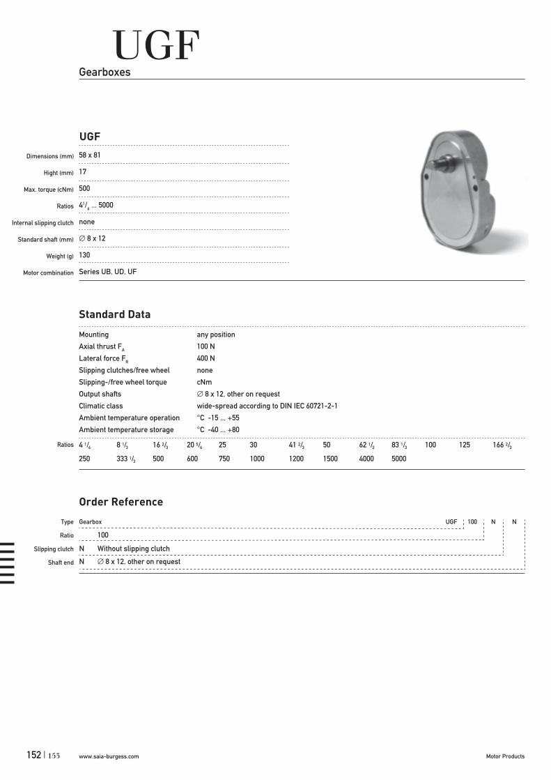
www.saia-burgess.com Motor Products152 |
UGFGearboxes
Standard Data
Mounting any position
Axial thrust FA 100 N
Lateral force FR 400 N
Slipping clutches/free wheel none
Slipping-/free wheel torque cNm
Output shafts 8 x 12, other on request
Climatic class wide-spread according to DIN IEC 60721-2-1
Ambient temperature operation °C -15 ... +55
Ambient temperature storage °C -40 ... +80
Ratios 4 1/6 8 1/3 16 2/3 20 5/6 25 30 41 2/3 50 62 1/2 83 1/3 100 125 166 2/3
250 333 1/3 500 600 750 1000 1200 1500 4000 5000
Type
Ratio
Slipping clutch
Shaft end
Gearbox UGF 100 N N
100
N Without slipping clutch
N 8 x 12, other on request
Order Reference
UGF
Dimensions (mm)
Hight (mm)
Max. torque (cNm)
Ratios
Internal slipping clutch
Standard shaft (mm)
Weight (g)
Motor combination
58 x 81
17
500
41/6 ... 5000
none
8 x 12
130
Series UB, UD, UF
153

www.saia-burgess.comMotor Products | 153
UGF
Dimensions
1
10
8
20
30
40
5060
80
100
200
300
4/
1
6 5
5/
5
66
/2
3
7/
1
2
8/
1
3 16
/2
3
25
33
/1
3
44
/2
3
50
58
/1
3 66
/2
3
75 8
3/
1
3
16
6
25
0
333
416
50
0
10
00
15
00
200
0
25
00
300
0
35
00
40
00
450
05
00
0
cNm
i
UFR4
UFM1 / U
FR3UFR
1UDR 1
UBR1 / U
DS 1
UBR2 / U
BR6
400
500600
Torque / ratio / life graph
motor torque with consideration for gear efficency
In combination with motors n=250 rpm, continuous operation and Tambient 10000 h 1000 h
In combination with motors n=500 rpm, continuous operation and Tambient 10000 h 1000 h
152
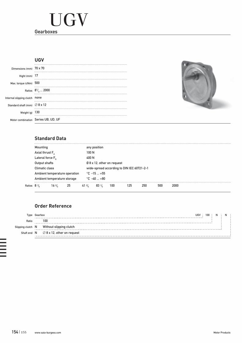
www.saia-burgess.com Motor Products154 |
UGVGearboxes
UGV
Dimensions (mm)
Hight (mm)
Max. torque (cNm)
Ratios
Internal slipping clutch
Standard shaft (mm)
Weight (g)
Motor combination
70 x 70
17
500
81/3 ... 2000
none
8 x 12
130
Series UB, UD, UF
8 1/3 16 2/3 25 41 2/3 83 1/3 100 125 250 500 2000
Standard Data
Mounting any position
Axial thrust FA 100 N
Lateral force FR 400 N
Output shafts Ø 8 x 12, other on request
Climatic class wide-spread according to DIN IEC 60721-2-1
Ambient temperature operation °C -15 ... +55
Ambient temperature storage °C -40 ... +80
Ratios
Type
Ratio
Slipping clutch
Shaft end
Gearbox UGV 100 N N
100
N Without slipping clutch
N 8 x 12, other on request
Order Reference
155

www.saia-burgess.comMotor Products | 155
Dimensions
UGV
1
10
8
20
30
40
5060
80
100
200
300
4/
1
6 5
5/
5
66
/2
3
7/
1
2
8/
1
3 16
/2
3
25
33
/1
3
44
/2
3
50
58
/1
3 66
/2
3
75 8
3/
1
3
16
6
25
0
333
416
50
0
10
00
15
00
200
0
25
00
300
0
35
00
40
00
450
05
00
0
cNm
i
UFR4
UFM1 / U
FR3UFR
1UDR 1
UBR1 / U
DS 1
UBR2 / U
BR6
400
500600
Torque / ratio / life graph
motor torque with consideration for gear efficency
In combination with motors n=250 rpm, continuous operation and Tambient 10000 h 1000 h
In combination with motors n=500 rpm, continuous operation and Tambient 10000 h 1000 h
154

www.saia-burgess.com Motor Products156 |
UGO/UGPSynchronous Motors
Rotational
Gearbox STG60 6 1/4 1 1
6 1/4
1 see next page drawings Dimension shaft end types234
1 through holes2 threaded holes (only STG61)
motor pinion: see page 159 Motor Pinion Data adapter plate: see page 160 for adapter plate
UGO/UGP (STG60/61)
Dimensions (mm)
Hight (mm)
Max. torque (cNm)
Ratios
Internal slipping clutch
Standard shaft (mm)
Weight (g)
Motor combination
65 x 65/68 x 68
29,8–38
600
6 1/4 ... 5400
none
8 x 22
230–330
5021–, 5022–, 5032RG–, 6443–, 6444– series
Standard Data
Mounting any positionMax. input speed 3000 min-1
Max. output torque 600 cNmMax. input -and output power please refer to table in Technical DataAverage back lash unloaded 1,5 degree
2–4 stages with 6 Nm 3 degree5–6 stages with 6 Nm 4 degree
Max. axial force FA 30 NMax. lateral force FR, 12 mm from lange 80 NMax. axial play 0,3 mmMax. radial play 20 μmWorking temperature 0 ... +50 °CAmbient temperature storage –40 ... +100 °C
6 1/4 12 1/2 18 3/4 37 1/2 46 7/8 62 1/2 93 3/4 125 150 187 1/2 375 7501500 2000 3750 5400
Type
Ratio
shaft end
fixing
optional
Order Reference
Ratio
UGO (STG 60) UGP (STG 61)
157

www.saia-burgess.comMotor Products | 157
UGO/UGP (STG 60/61)
shaft end types UGO/P (STG 60/61)
Technical Data
Ratio Stages * pinion type Weight Max. torque (cNm)
6 1/4 2 0,81 1 190 1,012 1/2 3 0,73 2 220 1,818 3/4 3 0,73 3 220 2,737 1/2 3 0,73 4 220 5,446 7/8 4 0,65 3 250 662 1/2 4 0,65 2 250 693 3/4 4 0,65 3 250 6125 4 0,65 2 250 6150 4 0,65 3 250 6187 1/2 4 0,65 4 250 6375 5 0,59 3 280 6750 5 0,59 4 280 61500 6 0,53 4 310 62000 6 0,53 4 310 63750 6 0,53 4 310 65400 6 0,53 5 310 6
Technical Data valid for a working temperature 0 °C ... +50 °C
* Direction of rotaton of output- and motor-shaft at 2,4 and 6 stages - same 3 and 5 stages - opposite
156
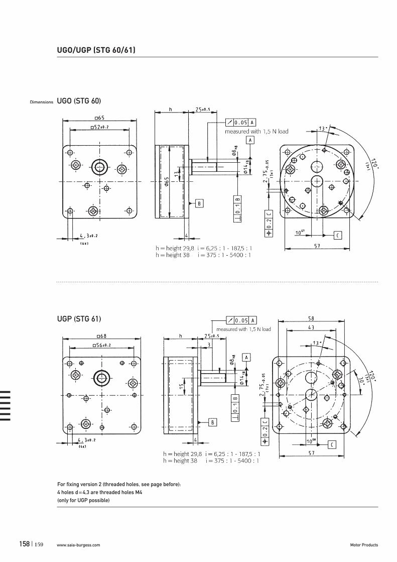
www.saia-burgess.com Motor Products158 |
UGO/UGP (STG 60/61)
UGO (STG 60)
UGP (STG 61)
159
For fixing version 2 (threaded holes, see page before):4 holes d = 4,3 are threaded holes M4(only for UGP possible)
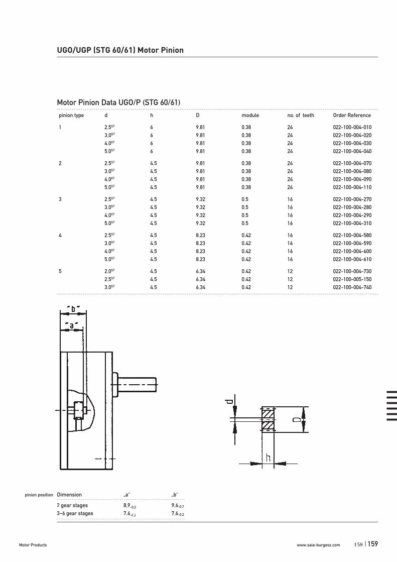
www.saia-burgess.comMotor Products | 159
UGO/UGP (STG 60/61) Motor Pinion
Motor Pinion Data UGO/P (STG 60/61)
158
3,0S7

www.saia-burgess.com Motor Products160 |
Ø
Ø
161

www.saia-burgess.comMotor Products | 161
UGJGearboxes
4 1/6 8 1/3 16 2/3 33 1/3 41 2/3 50 66 2/3 83 1/3 100 125 150 166 2/3 200
250 500 1000 2000 2500 3000 4000 5000 6250 8333 1/3 10000 12500 15000
20000 25000 30000 37500 60000 75000 120000 150000 300000 375000 750000 1500000 1800000
2250000 3000000 3600000 4500000 6000000 9000000 11250000 12000000 18000000 36000000
Standard Data
Mounting any position
Axial thrust FA 400 N
Lateral force FR 600 N
Output shafts 12 x 20, other on request
Climatic class wide-spread according to DIN IEC 60721-2-1
Ambient temperature operation °C -15 ... +55
Ambient temperature storage °C -40 ... +80
Ratios
Type
Ratio
Slipping clutch
Shaft end
Gearbox UGJ 100 N N
100
N Without slipping clutch
N 12 x 20, other on request
Order Reference
UGJ
Dimensions (mm)
Hight (mm)
Max. torque (cNm)
Ratios
Internal slipping clutch
Standard shaft (mm)
Weight (g)
Motor combination
65 x 107
28
1500
41/6 ... 36.000.000
none
12 x 20
480
Series UB, UD, UF, UH
160

www.saia-burgess.com Motor Products162 |
UGJ
Dimensions
130
40
5060
80
100
200
300
400
500
600
800
1000
2000
4/
1
6 5
5/
5
66
/2
3
7/
1
2
8/
1
3 16
/2
3
25
33
/1
3
44
/2
3
50
58
/1
3 66
/2
3
75 8
3/
1
3
16
6
25
0
33
3
416
50
0
10
00
15
00
20
00
250
030
00
35
00
40
00
45
00
50
00
cNm
i
UFR4UFM
1 / UFR
3
UFR1
UDR1
UBR1 / U
DS 1
UBR2 / U
BR6
Torque / ratio / life graph
motor torque with consideration for gear efficency
In combination with motors n=250 rpm, continuous operation and Tambient 10000 h 1000 h
In combination with motors n=500 rpm, continuous operation and Tambient 10000 h 1000 h
M3
20,7
15
30
4430.3
2321
23
69
25 25
0.5
282.5
106.6
64.6
16h7
6
8
6,2
R2
R3
12
16
30
R28
R20
17
Mounting with standard shaft type "N"
(Special shaft on request)
0 -0,0
27
0 -0,0
18
+0,02
2
0
163

www.saia-burgess.comMotor Products | 163
Gearbox STG 200 61/4
61/4
motor pinion: see page 165 Motor Pinion Data
UGR (STG 200)
Dimensions (mm)
Hight (mm)
Max. torque (cNm)
Ratios
Internal slipping clutch
Standard shaft (mm)
Weight (g)
Motor combination
UGRGearboxes
70 x 130
38
2000
6 1/4 ... 375
none
12 x 35
depends on ratio
5021–, 5022–, 5032 RG–, 6443–, 6444– series
Standard Data
Mounting any positionMax. input speed * 3000 min-1
Max. output torque * 2000 cNmMax. input -and output power * please refer to table in Technical DataAverage back lash unload 0,75°
2/3 stages with 4/10 Nm 1,25°4/5 stages with 15/20 Nm 2°
Max. axial force FA 60 NMax. lateral force FR, 20 mm from lange 80 NMax. axial play 0,3 mmMax. radial play 83 μmWorking temperature 10 ... +50 °CAmbient temperature storage –40 ... +100 °C
61/4 121/2 25 371/2 621/2 75 933/4 125 375
* Depends on ratio
Type
Ratio
optional
Order Reference
Ratio
162
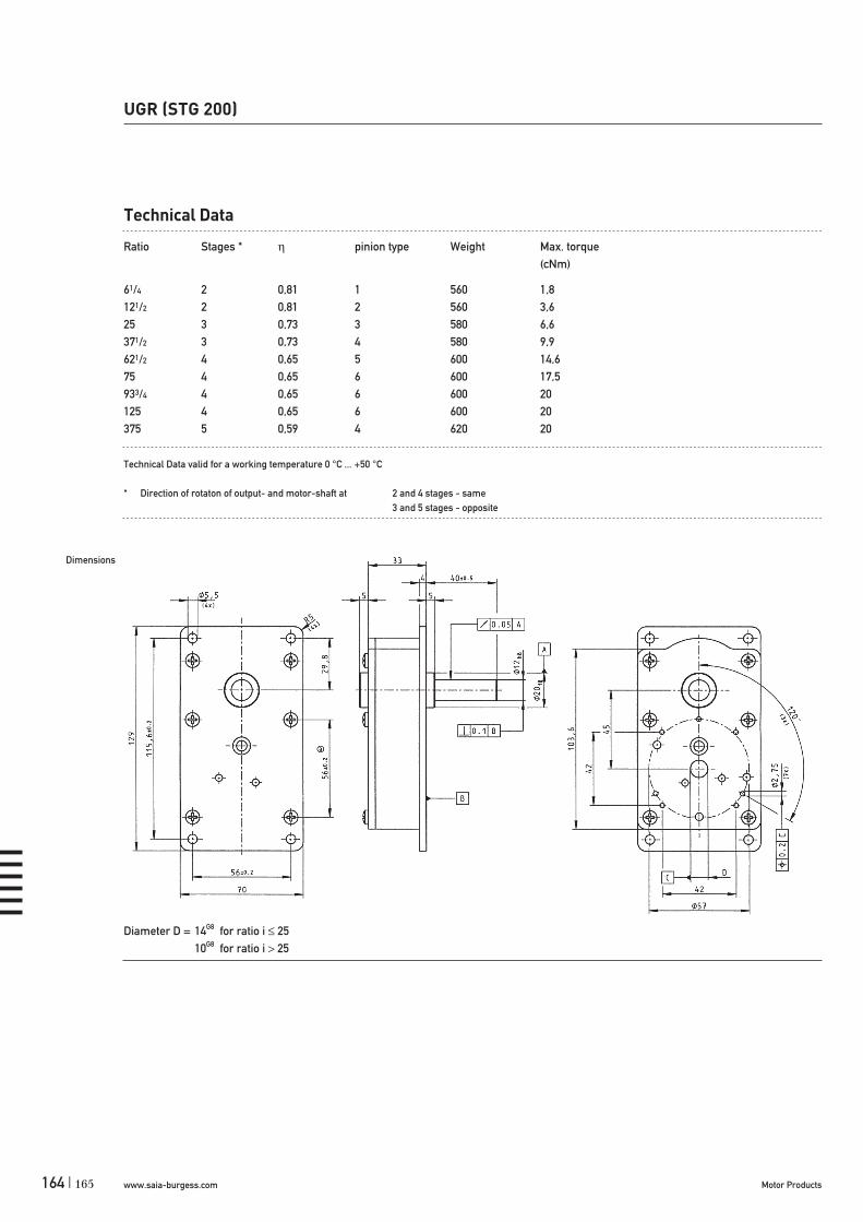
www.saia-burgess.com Motor Products164 |
UGR (STG 200)
Technical Data
Ratio Stages * pinion type Weight Max. torque (cNm)
61/4 2 0,81 1 560 1,8121/2 2 0,81 2 560 3,625 3 0,73 3 580 6,6371/2 3 0,73 4 580 9,9621/2 4 0,65 5 600 14,675 4 0,65 6 600 17,5933/4 4 0,65 6 600 20125 4 0,65 6 600 20375 5 0,59 4 620 20
Technical Data valid for a working temperature 0 °C ... +50 °C
* Direction of rotaton of output- and motor-shaft at 2 and 4 stages - same 3 and 5 stages - opposite
Dimensions
165
Diameter D = 14G8 for ratio i 2510G8 for ratio i 25

www.saia-burgess.comMotor Products | 165
UGR (STG 200)
pinion position Dimension „a“ „b“ max. „b“ min.
2 gear stages 16,1–0,2 28 103 gear stages 10,3–0,2 10,3 8,14 gear stages 15,1–0,2 15 8,1 (13,5 bei 5)5 gear stages 10,9–0,2 11 8,1
Motor Pinion Data
pinion type d h D module no. of teeth Order Reference
1 4,0X7 11,5 12,65 0,56 20 022-100-020-100 5,0S7 11,5 12,65 0,56 20 022-100-020-110
2 4,0X7 11,5 9,11 0,53 14 022-100-020-130 5,0S7 11,5 9,11 0,53 14 022-100-020-140
3 3,0S7 6,8 12,02 0,57 18 022-100-020-200 4,0X7 6,8 12,02 0,57 18 022-100-020-210 5,0S7 6,8 12,02 0,57 18 022-100-020-220
4 3,0S7 6,8 9,32 0,5 16 022-100-020-280 4,0X7 6,8 9,32 0,5 16 022-100-020-290 5,0S7 6,8 9,32 0,5 16 022-100-020-300
5 3,0S7 11,5 9,82 0,38 24 022-100-020-360 4,0X7 11,5 9,82 0,38 24 022-100-020-370 5,0S7 11,5 9,82 0,38 24 022-100-020-380
6 3,0S7 11,5 9,32 0,5 16 022-100-020-400 4,0X7 11,5 9,32 0,5 16 022-100-020-410 5,0S7 6,8 9,32 0,5 16 022-100-020-300
164

www.saia-burgess.com Motor Products166 |
Gearbox V250 61/4 1
371/2
1 see next page drawings Dimensions shaft234
motor pinion: on request
UGS (V 250)
Dimensions (mm)
Hight (mm)
Max. torque (cNm)
Ratios
Internal slipping clutch
Standard shaft (mm)
Weight (g)
Motor combination
UGSGearboxes
70 x 30
36
2500
37 1/2 ... 1500
none
12 x 35
depends on ratio
5021–, 5022–, 5032 RG–, 6443–, 6444– series
Standard Data
Mounting any positionMax. input speed * 3000 min-1
Max. output torque * 2500 cNmAverage back lash 1,5°Max. axial force FA 60 NMax. lateral force FR, 20 mm from lange 80 NMax. axial play 0,3 mmWorking temperature 10 ... +50 °CAmbient temperature storage –40 ... +100 °C
371/2 621/2 150 1871/2 375 750 1500
* Depends on ratio
Type
Ratio
Shaft type
optional
Order Reference
Ratio
167

www.saia-burgess.comMotor Products | 167
Picture Type d l l1 t d1
1 A 12h8 401 B 12h8 302 C 12h8 40 15 12 D 12h8 30 5 13 E 12h8 40 20 4h124 F 12h8 40 38
Type A: Standard
Technical Data
Ratio Stages *371/2 3 0,73621/2 4 0,65125 4 0,651871/2 5 0,59375 6 0,53750 6 0,531500 6 0,53
* Direction of rotaton of output- and motor-shaft at 2, 4 and 6 stages - same
3 and 5 stages - opposite
Dimension Shaft
UGS (V 250)
Picture 1 Picture 2 Picture 3 Picture 4
166

www.saia-burgess.com Motor Products168 |
UGS (V 250)
Dimensions
169


www.saia-burgess.com Motor Products170 |
Stepper motorsSpecified data for torque values is valid for – a duty cycle of 100%, in Performance
Charts additionally for 30% (cycle time: 5 min, type URG only 1 min.)
– an ambient temperature of 23 ±5°C– a defined driver circuitry, with constant
voltage supply – at rated voltage
If duty cycle or actual maximum ambient temperature is lower, the motor can be designed for higher performance (torque and power) by using a different winding.
Chopper driver circuits can be applied alter-natively to a driver with constant voltage supply.hey are more expensive, but bring higher perfor-mance. Additionally, they eliminate the effects of temperature and supply voltage change.
Performance charts available on request.
Step angle tolerance is about ±5% (not cumulative)
Synchronous motorsSpecified data for torque/power values are
valid for – a duty cycle of 100%– an ambient temperature of 23 ±5°C– at rated voltage– synchronous torque (not starting torque)
Torque is specified with maximum values, overloading is not permissible.
If duty cycle or actual maximum ambient temperature is lower, the motor can be designed with higher performance by using a different winding.
The basic design is the same as for our step-per motors, but the motors are operated by a sinuswaveform voltage.
A capacitor, connected to one of the motor coils, is necessary for rotation in the appropriate direction.
Motor type UDS is a special design: It has only one coil, but is fitted with an internal ratchet. This ratchet determines the direction of rotation. A capacitor is not necessary.
Mechanical and electrical connectionsOn request we can deliver other options, e. g. – special motor shafts– pinions on shaft – special cable lengths– connectors
Saia-Burgess Motors Important notes
GeneralAll specifications for torque, force and power
are representative only and maybe subject tovariation due to manufacturing tolerances.
Saia-Burgess motors, except UR types, fulfilbasis insulation requirements of EN 60335-1: 2004.
Application adviceThe requirements for protection class I, II
or III according to EN 60355-1: 2004 have to be fulfilled by customer application.
171
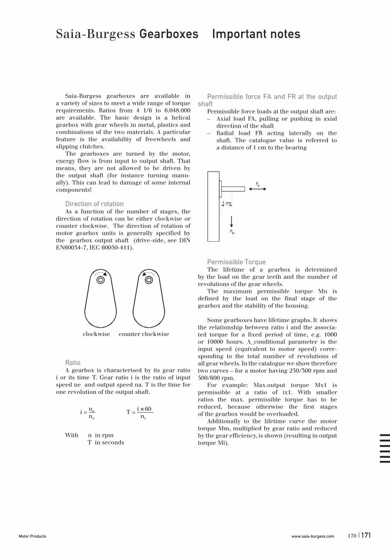
www.saia-burgess.comMotor Products | 171
Saia-Burgess gearboxes are available ina variety of sizes to meet a wide range of torquerequirements. Ratios from 4 1/6 to 6.048.000are available. The basic design is a helicalgearbox with gear wheels in metal, plastics andcombinations of the two materials. A particularfeature is the availability of freewheels andslipping clutches.
The gearboxes are turned by the motor,energy flow is from input to output shaft. Thatmeans, they are not allowed to be driven bythe output shaft (for instance turning manu-ally). This can lead to damage of some internalcomponents!
Direction of rotationAs a function of the number of stages, the
direction of rotation can be either clockwise orcounter clockwise. The direction of rotation ofmotor gearbox units is generally specified bythe gearbox output shaft (drive-side, see DINEN60034-7, IEC 60050-411).
RatioA gearbox is characterised by its gear ratio
i or its time T. Gear ratio i is the ratio of inputspeed ne and output speed na. T is the time forone revolution of the output shaft.
With n in rpm T in seconds
Permissible force FA and FR at the output shaft
Permissible force loads at the output shaft are:– Axial load FA, pulling or pushing in axial
direction of the shaft– Radial load FR acting laterally on the
shaft. The catalogue value is referred to a distance of 1 cm to the bearing
Permissible TorqueThe lifetime of a gearbox is determined
by the load on the gear teeth and the number ofrevolutions of the gear wheels.
The maximum permissible torque Mn isdefined by the load on the final stage of thegearbox and the stability of the housing.
Some gearboxes have lifetime graphs. It showsthe relationship between ratio i and the associa-ted torque for a fixed period of time, e.g. 1000or 10000 hours. A conditional parameter is theinput speed (equivalent to motor speed) corre-sponding to the total number of revolutions ofall gear wheels. In the catalogue we show thereforetwo curves – for a motor having 250/300 rpm and500/600 rpm.
For example: Max.output torque Mx1 ispermissible at a ratio of ix1. With smallerratios the max. permissible torque has to bereduced, because otherwise the first stagesof the gearbox would be overloaded.
Additionally to the lifetime curve the motortorque Mm, multiplied by gear ratio and reducedby the gear efficiency, is shown (resulting in outputtorque Mi).
Saia-Burgess Gearboxes Important notes
1 cm
FA
FR
clockwise counter clockwise
i = ne
na T = i 60 ne
×
170

www.saia-burgess.com Motor Products172 |
Example1: The application of motor 1combined with a gearbox of ratio ix1 leads toan output torque Mx1 at point A. The gearboxcan transmit this torque, meeting itslifetime.
If a ratio of i >ix1 is selected, actual torquewould be M > Mx1. However lifetime cannotbe guaranteed, as the operating point now liesabove of the lifetime curve.
Example 2: Motor 1 with a ratio of ix2. Torquegenerated is Mx2. This is below of the lifetimecurve. The transmission can operate for anextended period without difficulty
Example3: Motor 2 and a ratio of ix3give a torque of Mn. When using a ratioof i > ix3 - the gearbox cannot be loaded morethan Mn.
EfficiencyThe number of stages in the gearbox
determines the efficiency With high ratios of ithis factor will decrease below 10%, as the graphbelow shows. (For UGO/UGP, UGR and UGS seetable in the chapter)
ClutchesGearbox types UGA, UGB and UGD can be
fitted with freewheels or slipping clutches.Freewheels transmit the max. torque M inthe locked direction, <1 cNm in the oppositedirection. One way slipping clutches behavesimilarly except that the slip torque has a hig-her value. Two way slipping clutches can onlytransmit a limited torque value in eitherdirection lower than the slip torque.
Slipping clutches are used to: Protect thegearbox against torque overloads, or to adjustthe load by turning from the load side (remember:turning the output shaft directly can otherwisedamage the gearbox).
Saia-Burgess Gearboxes Important notes
Efficiency
0
10
20304050
60
70
80
10 100 1000 10000 100000
Transmission ratio i
Eff
icie
ncy
(%
)
Efficiency
0
10
20304050
60
70
80
10 100 1000 10 000 100 000
Transmission ratio i
Eff
icie
ncy
(%
)
Slipping clutch One way One way Two way
Freewheel yes yes no
Torque,clockwise
full torque < slipping torque < slipping torque
Torquecounter-clockwise
< slipping torque full torque < slipping torque
Output shaftturning, clockwise
slipping possible blocking slipping possible
Output shaftturning,counter-clockwise
blocking slipping possible slipping possible
log i
log M
nM
Mx1
Mx2
ix1ix2 ix3
A
Motor 1 Motor 2
Mi = Mm x i x G
.
.
173

www.saia-burgess.comMotor Products | 173
Power consuption PinThe power consumtion expressed in W was
determined in no-load operation
LoadThe total sum of all static and dynamic mo-
ments (e.g. friction moment, mass inertia, actingon the rotor).
Speed nrmp revolution per minute
TorqueThe running torque in cNm (also synchro-
nous, braking or dynamic torque) defines theload at which the synchronous motor falls out ofsynchronism and stalls.
Power outputThe power output expressed in W is determi-
ned according to the following formula
Pout = Md x 2 x n = [W]
Md in Nm (1 cNm = 0,01 Nm), n in rpm
Pole pair numberThe number of rotor pole pairs North/South.
Direction of rotationThis information always refers to the output
shaft, either of the motor or of the gearbox.Right = clockwise rotation (CW), Left = counterclockwise rotation (CCW)
Gear torqueThe maximum gear torque in cNm defines the
maximum load for a required life of at least 1000operating hours.
Running timeThis value refers to the time (t) per revolution
(U); they are calculated using the following for-mula
t/U = i x 60 = [sec.]
i = transmition ration = motor speed
Axial thrust / lateral force / lateral torqueThese values refer to the loads on the standard
output shaft of the respective gear.The permissible lateral torque referring to the
standard shaft must not be exceeded on specialshafts either.
Common Explanations of characteristics
60
n
172

www.saia-burgess.com Motor Products174 |
SynchronousThe running of the rotor at the same speed
as the stator field which is determined by thefrequency of the supply
Synchronous speedConstant speed of rotation at constant fre-
quency based upon the number of pole pairs ofthe motor
n = f x 60°
f = frequency (Hz), n = speed of rotationp = number of pole pairs
Synchronous torqueTorque which the motor is still capable of
producing without falling out of synchronism,once the synchronous speed of rotation has beenreached.
Starting torqueLoad torque the motor is capable to start.It is influenced by the type and manner of
coupling to the load, the load inertia, the gear-box design and the supply voltage. In the caseof a very large reduction ratio a small externalmoment of inertia and nominal gearbox play thestarting torque becomes equal to the synchro-nous torque.
Detent torque (static)Defines the maximum torque which can be
applied to a deenergised motor without causingthe motor to rotate. Catalogue specifications referto the static detent torque.
Detent torque (dynamic)Defines the maximum torque at which the
motor comes to an immediate standstill from syn-chronous running when the excitation current isswitched off.
Permissible load inertiaIs the maximum inertia load the motor can start
without external help.
Stall-proofSynchronous motors with permanent magnet
rotors can be stalled without damage to the motorwinding.
Torque limit (Torque limited motors)The constant torque produced by the hyste-
resis-magnetic clutch within the torque limitedsynchronous motor in the stalled condition.
Design characteristicsThe basic design is the same as for our stepper
motors, but the motors are operated by a sinuswaveform voltage.
General technical terms relating to the synchronous
motor and torque limited synchronous motor
.
p
175

www.saia-burgess.comMotor Products | 175
ED or Duty CycleDuty cycle of operation, based on a cycle time
of 5 minutes (1 minute for URG) and a frequencyf=0Hz; e.g. ED=30% means that the motor canbe continuously powered 1.5 minutes (30% of 5minutes) without overheating
StepRotary movement of the rotor through one
step angle.
Step angleRotary angle through which the motor shaft
turns per controlled pulse.
Stepping frequency Number of steps of the stepping motor in 1
sec.
DriverElectronics which convert step and direction
input signals to high power currents and voltagesto drive a step motor.
Unipolar driver Unipolar means that every coil end has one po-
larity only A unipolar coil consists in fact of 2 coils.Alternating the current flows through one of thesecoils and in one direction. Compared to a bipolarmotor only half of the copper is used at time.
The motor phase winding must be center tap-ped. On the SAMOTRONIC101 this is already fixedon the board.
Often an additional Zener diode is used toensure a fast current decay in the switched-off coil.This will give an increased motor torque especiallyat higher frequencies.
Torque graphs in this catalogue are measuredwith a 10V Zener diode.
Bipolar DriverBipolar indicates that every coil end is bipolar,
during driving it will be „+“ as well as „-“.Sinceevery coil is fully used the motor has a highertorque compared to a unipolar one.
Very often a bipolar driver has a constant cur-rent drive capability (also called chopper). Thatwill give an increased torque output on higherfrequencies and a lower influence of temperatureand supply voltage variations. Typical applicationsuse the SAMOTRONIC102.
General technical terms relating to the stepper motor
.
174
www.saia-burgess.com Motor Products176 |
Rotational speedRevolutions of the motor per minute calcula-
ted from:
n = f x x 60
f = stepping frequency, = step angle.
Detent torque (static)Defines the maximum torque which can be
applied to a deenergised motor without causingthe motor to rotate. Catalogue specifications referto the static detent torque.
Holding torqueDefines the maximum torque with which an
energized motor can be loaded without givingrise to a continuous rotary movement.
Pull-in torqueOperation torque when switching on step
frequency at once, without a ramp.
pull-out torqueOperation torque when applying an accelera-
tion / deceleration ramp.
Load inertia moment The sum of all the mass inertia moments occur-
ring on the shaft of the stepping motor.
Steps/revs The number of steps per 360° rotation.
Maximum operating torque The maximum torque which a stepper motor
without external mass inertia can generate withoutstepping losses.
General technical terms relating to the stepper motor
360°
177