Embed Size (px)
Citation preview

Additives & InstrumentsA member of
Betriebsanleitung
Manual
Measure what you see.
esp-10
D E2006/04
218 010 695
esp-10Einzelschlagprüfgerät
Bestell-Nr. 5200
esp-10Single-Impact Tester
Cat. No. 5200
Gardner
esp-10in accordance withBMW standardDBP 3431390
3 bar
Pressure only displayed
if sample is appliedDruckanzeige nur bei
aufgelegter Probe

Bedienungsanleitung
esp-10Einzelschlagprüfgerät
Bestell-Nr. 5200
Inhaltsverzeichnis
1. Sicherheitshinweise2. Anschluss an das Druckluftnetz3. Einstellen des Arbeitsdruckes
von 3 bar4. Kalibration5. Ausführung der Schlagprüfung6. Ausmessen des Einzelschlages7. Auswechseln des Schlagbolzens8. Technische Daten9. Wartung und Reinigung10.Lieferumfang/Lieferhinweise
Technische Änderungen vorbehalten.
Deutsch
Gardner
esp-10in accordance withBMW standardDBP 3431390
3 bar
Pressure only displayed
if sample is appliedDruckanzeige nur bei
aufgelegter Probe

Abb. 1
esp-10
Einzelschlagprüfgerät
1 Verriegelungsknopf desDruckminderers
2 Manometer3 Auflageplatte mit
Verriegelungsstiftund Schlagbolzenöffnung
4 Gegengewicht5 Schlagzähler6 Auslösehebel
Gardner
esp-10in accordance withBMW standardDBP 3431390
3 bar
Pressure only displayed
if sample is appliedDruckanzeige nur bei
aufgelegter Probe
1
2
3
4
5
6
esp-10
Einzelschlagprüfgerät
• Das Einzelschlagprüfgerätesp-10 auf eine ebene, horizonta-le, rutschsichere Fläche stellen.
Der Arbeitsdruck darf 3 bar nichtüberschreiten.
• Die Spalthöhe zwischen Auflage-tisch und Gegengewicht darf max.8 mm betragen und muss in regel-mässigen Abständen geprüftwerden.
1. Sicherheitshinweise
!
• Verriegelungsknopf nach vorneziehen und durch Drehen denArbeitsdruck einstellen, bis 3 baram Manometer abzulesen sind,dabei mehrmals rechten Auslöse-hebel (6) betätigen, um genaueDruckeinstellung zu gewährlei-sten.
• Danach Verriegelungsknopf (1)durch Zurückschieben wiederfeststellen. Das Gerät ist jetztbetriebsbereit.
3. Einstellen des Arbeits-
druckes von 3 bar
• Druckluftschlauch mit dem offe-nen Ende an den rückwärtigenAnschluss (R1/8") anbringen undmit der Überwurfmutter befesti-gen.
• Anderes Schlauchende mitEinstecknippel (NW 7,2 mm) andie Schnellkupplung derDruckluftversorgung (max. 5 bar)anschließen.
• Die Druckluft sollte ölfrei unddurch einen Wasserabscheiderentfeuchtet sein
• Bei einer Trennung der Luftzufuhrist zuerst die Schnellkupplung derDruckluftversorgung, welche inerreichbarer Nähe sein sollte, zulösen, anschließend erst dieÜberwurfmutter.
2. Anschluss an das
Druckluftnetz

4. Kalibrierung Druckluft auf 300 kPa (3bar) einstel-len.
Die Schneide prüfen. Der Schlag-körper muss unbeschädigt, glattund frei von Belägen sein. Bei Be-schädigungen ist er auszutauschen.
Zur Kalibrierung des Prüfgerätesanstelle einer beschichtetenProbenplatte den Kalibrierstandardauf den Schlagkörper des Prüfgerä-tes legen, mit einem Gegengewicht(Masse 1 kg) beschweren und dieSchlagprüfung auslösen.
Mit einem Messmiskroskop die Brei-te des Eindruckes messen. Die mitt-lere Breite mit den Sollwerten desKalibrierstandards vergleichen.Weicht der gemessenden Wert vomSollwert um mehr als 10μm ab, soist das Gerät nach den Angaben derHerstellers zu justieren.
Breite des Eindruckes imKalibrierstandard
• Das esp-10 Einzelschlagprüfgerätist bestimmt zur Prüfung von ein-oder mehrschichtigen Beschich-tungen. Zur Prüfung werden planePrüfbleche mit einer Dicke von0,7 - 1,0 mm verwendet.Für Personen- oder Sachschädendurch nicht bestimmungsgemässeVerwendung wird keineHerstellergarantie gewährt.
• Prüfblech mit der zu prüfendenLackfläche nach unten auf dieAuflageplatte (3) legen. Prüfblechmit dem Gewicht (4) beschweren.
• Die beiden seitlichen Auslöse-hebel (6) gleichzeitig kurz nachunten drücken.
• Der Schlagzähler (5) registriertjeden Schlag des Bolzens. DieLebensdauer des Bolzens beträgtca. 1.000 Schläge, er mussdanach ausgetauscht werden.
5. Ausführung der
Schlagprüfung
• Das esp-10 ist nicht geeignet fürandere Materialien als die vorge-gebenen Prüfbleche aus Metall.Es darf kein Glas oder ähnlicheMaterialien verwendet werden, dadurch Bruch oder Splittern Verlet-zungsgefahr besteht.

• Nach dem Beschuss die Prüfstel-len mit einem Klebeband-abrissvon losen Lackteilchen befreien.
• Danach die Breite B der abge-platzten Schicht ausmessen undauf ganze mm aufrunden. DieBreite des in den Grundwerkstoffeingedrungenen Keils bleibtunberücksichtigt.
6. Ausmessen des
Einzelschlages
• Trennebene bestimmen.Bei mehreren Trennebenen dieAnteile prozentual abschätzen.In Zweifelsfällen und besondersbei geringen Farbunterschiedenempfiehlt es sich, ein Mikro-skop zur genaueren Bestim-mung der Trennebenen zubenutzen.
ca. 100 μm
Schlagbolzen
Abb. 2 Mehrschichtlackierung mit Eindringkörper
- Decklack
- Füller
- Grundierung- Phosphatierung
- Blech

• Gerät von der Druckluftzufuhrtrennen.
• Die 4 Kreuzschlitzschrauben ander Rückwand entfernen.
• Rückwand mit Halter leicht nachhinten neigen und nach oben überdas Kontergewicht führen.
• Kontergewicht von der Andruck-platte abheben.
• Mit einem metrischen 2,5 mmInnensechskantschlüssel (Inbus)die 2 Schrauben unterhalb derAuflageplatte lösen.
• Auflageplatte vorsichtig nachoben abheben. Schlagbolzen undFeder liegen nun frei auf demFührungsschacht.
• Vorsichtig den Schlagbolzen unddie Feder entfernen.
• Gerät auf den Kopf halten, um dieKugel aus dem Führungsschachtherauszunehmen.
7. Auswechseln des
Schlagbolzens
• Kugel auf Unversehrtheit prüfen.Kugel zurück in den Führungs-schacht geben bzw. gegebenen-falls ersetzen.
• Feder auflegen.
• Schlagbolzen auf Unversehrtheitprüfen und gegebenenfallsaustauschen.
• Schlagbolzen auflegen.
• Alle Teile in umgekehrter Reihen-folge zusammensetzen

Technische Daten
Anschluss fürDruckluftschlauch: R 1/8"
Schnellverschlussfür die (zentrale)Druckluftversorgung: NW 7,2 mm
ErforderlicheDruckluftversorgung: 5 bar
Arbeitsdruck: 3 bar
Lebensdauer des ca. 1.000Schlagbolzens: Schläge
Auflagegewicht: 1750 g
Durchmesser desGewichts: ø 60 mm
Temperaturbereich:-10°C bis +60°C Lagerung+15°C bis +40°C Betrieb
Rel. Luftfeuchtigkeit:bis 85% nichtkondensierend
8. Technische Daten/
NormDauerschalldruckpegel:< 70 dB(A)
Abmessungen (B x H x L):320 x 220 x 450 mm
Gesamtgewicht: 8520g
Norm
DIN EN ISO 20567-2

9. Wartung und Reinigung
Lackreste an der Beschußöffnungsind in regelmäßigen Abständen miteinem feuchten Tuch zu entfernen.Keine Lösemittel verwenden.
Fehlerbeschreibung:• Eindruck nicht homogen:
Prüfen Sie, ob der Schlagkörpernoch unbeschädigt ist oder sichLackreste am Schlagkörperbefinden. Beachten Sie hierzudas Kapitel „Auswechseln desSchlagbolzens“.
• Eindruck geht nicht bis zumSubstrat durch oder ist nicht klarerkennbar: Prüfen Sie den Druckam Manometer (3 bar).
• Druckverlust durch Undichtigkeitam Gerät:Kontaktieren Sie unseren techni-schen Service.
10. Lieferumfang
Einzelschlagprüfgerät esp-10
GewichtAnschlussschlauchBedienungsanleitung
Entsorgung:• Das esp-10 bzw. alle Teile des
Gerätes sind gemäß ihres Werk-stoffes bzw. ihrer Kennzeichnungunter Berücksichtigung derjeweiligen gesetzlichen Bestim-mungen fachgerecht zu entsor-gen.
10. Lieferhinweise
Kat.Nr. Artikel
5200 Einzelschlag-prüfgerät esp-10
5201 Schlagbolzen,Ersatz
5202 Gewicht, Ersatz
5824 Präzisionsmikroskopmit Beleuchtung
5205 Kalibrierstandard

EG - Konformitätserklärung
EC - Declaration of Conformity
Wir / We, BYK-Gardner GmbH, Lausitzer Straße 8, D - 82538 Geretsried
erklären im Sinne der EG-Richtlinie(n): / declare in accordance with the EC Directive(s):
• Maschinen 98/37/EG / Maschines 98/37/EG
Die Bauart des Produktes: / The construction of the product:
esp-10 Einzelschlagprüfgerät / esp-10 Single-Impact Tester
ist entwickelt, konstruiert und gefertigt in Übereinstimmung mit vorgenannter(n) EG-Richtlinie(n). / wasdeveloped, constructed and produced in accordance with a.m. EC Directive(s).
Weitere entsprechende sicherheitsrelevante Normen wurden berücksichtigt. / Further safety relevantstandards were observed. DIN EN ISO 12100 - 1+2, DIN EN 983
Eine Technische Dokumentation ist vorhanden. / A Technical Documentation is available.
BYK-Gardner GmbH
Dr. Georg SchroederGeschäftsführer / Managing Director
F Déclaration de conformité - Nous, BYK-Gardner GmbH, déclarons que les produits / instruments ci-dessusmentionnés ont été développés, produits et construits en conformité avec les directives CEE établies.
Konformitetserklæring - Vi, BYK-Gardner GmbH, erklærer herved, at ovennævnte produkter / instrumenter erudviklet, konstrueret og produceret i overensstemmelse med de angivne EU Direktiver.
Declaración de Conformidad - Nosotros, BYK-Gardner GmbH, declaramos que los productos / aparatos arribamencionados, han sido desarrollados, construídos y fabricados en consonancia con las directrices de la CEEindicadas.
EU-yhteensopivuusvakuutus - Me, BYK-Gardner GmbH, vakuuttaa, että yllämainitut tuotteet / laitteet on kehitetty,rakennettu ja valmistettu asetettujen EU-direktiivien mukaisesti.
Dichiarazione di conformità - Noi, BYK-Gardner GmbH, dichiariamo che i suddetti prodotti / strumenti sono statisviluppati, construiti et prodotti in conformità con le Direttive EC stabilite.
Overeenkomstigheidsverklaring - Wij, BYK-Gardner GmbH, verklaren hierbij dat bovengenoemd produkten /apparaten zijn ontworpen, gekonstrueerd en vervaardigd overeenkomstig de genoemde EG-richtlijnen.
Declaração de Conformidade - Nós, BYK-Gardner GmbH, declaramos pela presente, que os produtos /aparelhos acima indicados são desenvolvidos, construídos e produzidos de acordo com as Directivas CEmencionadas.
Δη´λωση ΕΚ−συμμο´ρφωσηs − Εμει´s, η BYK-Gardner GmbH, δηλω´νουμε με το παρο´ν ο´τι τα ωs α´νω αναφερο´μενα
προι´ο´ντα / συσκευε´s αναπτυ´χθηκαν σχεδια´στηκαν και κατασκευα´στηκαν σε συμφωνι´α με τιs προαναφερο´´μενεsοδηγι´εs ΕΚ.
Deklaration av överenstämmelse - Vi, BYK-Gardner GmbH, deklarerar härmed att ovanstående produkter /instrument har blivit utvecklade och tillverkade i enlighet med de gällande EU direktiven.
GR
S
NL
I
SF
DK
E
P

BYK-Gardner USA
9104 Guilford RoadColumbia, Md 21046USAPhone 800-343-7721
301-483-6500Fax 800-394-8215
301-483-6555
BYK-Gardner GmbH
Lausitzer Str. 8D-82538 GeretsriedGermanyTel. 0-800-gardner
(0-800-4273637)+49-8171-3493-0
Fax +49-8171-3493-140
www.bykgardner.com

esp-10Einzelschlagprüfgerät
Bestell-Nr. 5200
esp-10Single-Impact Tester
Cat. No. 5200
D E2006/04
218 010 695Gardner
esp-10in accordance withBMW standardDBP 3431390
3 bar
Pressure only displayed
if sample is appliedDruckanzeige nur bei
aufgelegter Probe

Operating Instructions
esp-10Single-Impact Tester
Catalog No. 5200
Contents
1. Safety Information2. Connection to the Compressed-
air System3. Adjusting the Working Pressure
of 3 bar
4. Calibration
5. Procedure of the Chipping Test6. Measuring the Impact7. Replacing the Impact Tool8. Technical Data9. Maintenance and Cleaning10.Components / Ordering Guide
Technical Data are Subject to Alterations.
English
Gardner
esp-10in accordance withBMW standardDBP 3431390
3 bar
Pressure only displayed
if sample is appliedDruckanzeige nur bei
aufgelegter Probe
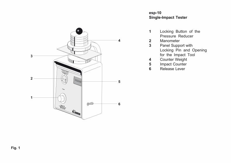
Fig. 1
Gardner
esp-10in accordance withBMW standardDBP 3431390
3 bar
Pressure only displayed
if sample is appliedDruckanzeige nur bei
aufgelegter Probe
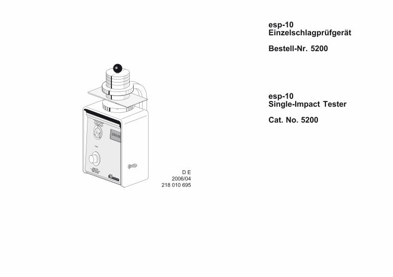
esp-10
Single-Impact Tester
1 Locking Button of thePressure Reducer
2 Manometer3 Panel Support with
Locking Pin and Openingfor the Impact Tool
4 Counter Weight5 Impact Counter6 Release Lever
1
2
3
4
5
6

esp-10
Single-Impact Tester
• Place the Single-Impact Testeresp-10 on a flat, horizontal, non-slip surface.
The working pressure must notexceed 3 bar.
• The gab size between panelsupport and counter weight mustnot exceed 8 mm and must beexamined frequently.
1. Safety Information
!
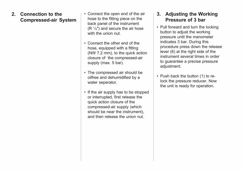
• Pull forward and turn the lockingbutton to adjust the workingpressure until the manometerindicates 3 bar. During thisprocedure press down the releaselever (6) at the right side of theinstrument several times in orderto guarantee a precise pressureadjustment.
• Push back the button (1) to re-lock the pressure reducer. Nowthe unit is ready for operation.
3. Adjusting the Working
Pressure of 3 bar
• Connect the open end of the airhose to the fitting piece on theback panel of the instrument(R 1/8") and secure the air hosewith the union nut.
• Connect the other end of thehose, equipped with a fitting(NW 7.2 mm), to the quick actionclosure of the compressed-airsupply (max. 5 bar).
• The compressed air should beoilfree and dehumidified by awater seperator.
• If the air supply has to be stoppedor interrupted, first release thequick action closure of thecompressed-air supply (whichshould be near the instrument),and then release the union nut.
2. Connection to the
Compressed-air System

Set the compressed air to 300 kPa(3 bar).
Examine the edge. The indentationbody may not show any defect, itshall be smooth and free from anydeposit. If it shows any damage,exchange it.
For calibration of the test apparatus,place the calibration standard onthe indentation body instead of acoated test panel, place acounterweight of 1 kg on it and startthe impact.
Measure the width if the impactusing the microscope. Compare theaverage width with the nominalvalue of the calibration standard. ifthe measured value differs by morethan 10 μm from the nominal value,calibrate the apparatus inaccordance with the manufacturer’sinstructions.
Width of the indentation in thecalibration standard
4. Calibration

• The esp-10 single impact tester isdedicated to test single- or multilayer coatings.Plane panels with a thickness of0.7 - 1 mm are used for the test.In case of misuse no warranty willbe garanted for damages topersons or objects.
• Place the test panel on thesupport (3) with the test surfacedown. Place the weight (4) on thetest panel.
• Briefly press down both lateralrelease levers (6) at the sametime.
• The impact counter (5) recordsevery impact of the impact tool.The operational life of the impacttool is approx. 1,000 impacts. Itmust then be exchanged.
5. Procedure of the
Chipping Test
• The esp-10 is not siutable forsubstrates other than therecommended metal panels.No glass or comparable materialsare to be used due to a seriousrisk of insury by sliver andbreakage.

• After the impact use adhesivetape to remove loose paintparticles from the test surface.
• Measure the width B of the areachipped off and round up to awhole number (mm). The width ofthe wedge-shaped tool thatpenetrated into the basis materialis not to be considered.
6. Measuring the Impact • Determine the separation plane.If there are several separationplanes estimate the percentage ofthe damaged area. In case ofdoubt and especially in case ofslight color differences it isrecommended to use amicroscope for a precisedetermination of the separationplanes.
approx. 100 μm
Impact Tool
Fig. 2 Multi-coat System with Impact Tool
- Finishing Paint
- Filler
- Priming Coat- Phosphating
- Panel

• Disconnect the instrument fromthe compressed-air supply.
• Remove the 4 cross-head rearpanel screws.
• Slightly tilt the raer panel withholder backwards and remove itby carefully pulling it up andguiding it beyound thecounterweight.
• Remove the counterweight fromthe panel support.
• Loosen the 2 screws below thepanel support using a metric 2.5mm hexagon socket screw key.
• Carefully raise and remove thepanel support so that the springand the impact tool lie bare on theguide tube.
• Carefully remove the impact tooland the spring.
• Hold the instrument upside-downin order to remove the ball fromthe guide tube.
7. Replacing the
Impact Tool
• Check the ball for any defects.Then put the ball back in theguide tube or replace itrespectively.
• Put the spring in place.
• Check the impact tool for anydefects and replace it ifnecessary.
• Put the impact tool in place.
• Re-assemble all other parts inreverse order.

8. Technical Data /
Standard
Technical Data
Connection forcompressed-airhose: R 1/8"
Quick acting closurefor the (centralized)compressed-airsupply: NW 7.2 mm
Requiredcompressed-airsupply: 5 bar
Working pressure: 3 bar
Operational life of approx.the impact tool: 1,000 impacts
Additional 1,750 gweight: (3.9 lbs.)
Diameter of theweight: ø 60 mm
Temperature range:-10°C bis +60°C storage+15°C bis +40°C working
Rel. humidity:up to 85% non condensing
Permanent sound pressure level:< 70 dB(A)
Dimensions (W x L x H):320 x 220 x 450 mm
Weight: 8520g
Standard
DIN EN ISO 20567-2

9. Maintenance and
Cleaning
Remaining paint chips at theopening need to be removedfrequently with a wet cloth.Do not use solvents.
Error description: • Impact does not appear
homogenious:Check impact tool for damageand remaining paint scrap. Pleaserefer also to chapter: "Exchangeof impact tool".
• Impact does not penetratethrough substrate or is not clearlyperceirable: Check air pressuregage (3 bar).
• Pressure loss in account of aleakage inside of the instrument:Please contact BYK-GardnerTechnical Service.
10. Components
esp-10 Single Impact TesterWeightConnection hoseOperating instructions
10. Ordering Guide
Cat.No. Description
5200 esp-10
Single-Impact Tester
5201 Impact Tool,Replacement
5202 Weight,Replacement
5824 Precision Microscope
5205 Calibration Standard
Disposal: • The esp-10 and all of it's parts are
to be disposed according tomaterial or labeling in conside-ration of legal requirements.
EG - Konformitätserklärung
EC - Declaration of Conformity
Wir / We, BYK-Gardner GmbH, Lausitzer Straße 8, D - 82538 Geretsried
erklären im Sinne der EG-Richtlinie(n): / declare in accordance with the EC Directive(s):
• Maschinen 98/37/EG / Maschines 98/37/EG
Die Bauart des Produktes: / The construction of the product:
esp-10 Einzelschlagprüfgerät / esp-10 Single-Impact Tester
ist entwickelt, konstruiert und gefertigt in Übereinstimmung mit vorgenannter(n) EG-Richtlinie(n). / wasdeveloped, constructed and produced in accordance with a.m. EC Directive(s).
Weitere entsprechende sicherheitsrelevante Normen wurden berücksichtigt. / Further safety relevantstandards were observed. DIN EN ISO 12100 - 1+2, DIN EN 983
Eine Technische Dokumentation ist vorhanden. / A Technical Documentation is available.
BYK-Gardner GmbH
Dr. Georg SchroederGeschäftsführer / Managing Director

F
GR
S
NL
I
SF
DK
E
P
Déclaration de conformité - Nous, BYK-Gardner GmbH, déclarons que les produits / instruments ci-dessusmentionnés ont été développés, produits et construits en conformité avec les directives CEE établies.
Konformitetserklæring - Vi, BYK-Gardner GmbH, erklærer herved, at ovennævnte produkter / instrumenter erudviklet, konstrueret og produceret i overensstemmelse med de angivne EU Direktiver.
Declaración de Conformidad - Nosotros, BYK-Gardner GmbH, declaramos que los productos / aparatos arribamencionados, han sido desarrollados, construídos y fabricados en consonancia con las directrices de la CEEindicadas.
EU-yhteensopivuusvakuutus - Me, BYK-Gardner GmbH, vakuuttaa, että yllämainitut tuotteet / laitteet on kehitetty,rakennettu ja valmistettu asetettujen EU-direktiivien mukaisesti.
Dichiarazione di conformità - Noi, BYK-Gardner GmbH, dichiariamo che i suddetti prodotti / strumenti sono statisviluppati, construiti et prodotti in conformità con le Direttive EC stabilite.
Overeenkomstigheidsverklaring - Wij, BYK-Gardner GmbH, verklaren hierbij dat bovengenoemd produkten /apparaten zijn ontworpen, gekonstrueerd en vervaardigd overeenkomstig de genoemde EG-richtlijnen.
Declaração de Conformidade - Nós, BYK-Gardner GmbH, declaramos pela presente, que os produtos /aparelhos acima indicados são desenvolvidos, construídos e produzidos de acordo com as Directivas CEmencionadas.
Δη´λωση ΕΚ−συμμο´ρφωσηs − Εμει´s, η BYK-Gardner GmbH, δηλω´νουμε με το παρο´ν ο´τι τα ωs α´νω αναφερο´μενα
προι´ο´ντα / συσκευε´s αναπτυ´χθηκαν σχεδια´στηκαν και κατασκευα´στηκαν σε συμφωνι´α με τιs προαναφερο´´μενεsοδηγι´εs ΕΚ.
Deklaration av överenstämmelse - Vi, BYK-Gardner GmbH, deklarerar härmed att ovanstående produkter /instrument har blivit utvecklade och tillverkade i enlighet med de gällande EU direktiven.

BYK-Gardner GmbH
Lausitzer Str. 8D-82538 GeretsriedGermanyTel. 0-800-gardner
(0-800-4273637)+49-8171-3493-0
Fax +49-8171-3493-140
www.bykgardner.com
BYK-Gardner USA
9104 Guilford RoadColumbia, Md 21046USAPhone 800-343-7721
301-483-6500Fax 800-394-8215
301-483-6555

218 010 695 DE 1403