Embed Size (px)
Citation preview

ImmersionRC | EzOSD Manual 1
EzOSD Manual Overview & Operating Instructions Preliminary. April 2009
EzOSD AnleitungBeschreibung und Übersicht

ImmersionRC | EzOSD Manual 2
Contents Overview ....................................................................................................................................................... 3
Features ........................................................................................................................................................ 3
Installation .................................................................................................................................................... 3
1. Installation using an ImmersionRC camera and transmitter ............................................................ 4
2. Installation without using the sensor board. .................................................................................... 5
Video Standard.......................................................................................................................................... 5
Switch Functions ....................................................................................................................................... 5
Preferences Menu ................................................................................................................................. 5
Show Flight Debriefing .......................................................................................................................... 6
OSD Display Layout ................................................................................................................................... 8
Alarms ....................................................................................................................................................... 9
Units ........................................................................................................................................................ 10
Flight ........................................................................................................................................................... 11
Telemetry, and Tracking Antenna ............................................................................................................... 11
Upgrading Firmware ............................................................................................................................... 12
Diagnostics, Q/A ...................................................................................................................................... 12
Thank You… ................................................................................................................................................. 16
InhaltsverzeichnisÜbersicht 3Features 3Einbau 3 1. Einbau mit einer Immersion RC Kamera und Sender 4 2. Einbau ohne Sensorboard 5Videostandard 5Schalterfunktionen 5Einstellungen 5Flugdaten Debrifing 6OSD Displayanzeige 8Alarme 9Einheiten 10Fliegen 11Antennentracking und Telemetrie 11 Aktualisieren der Firmware 12 Problemlösungen 12Vielen Dank 16
ImmersionRC | EzOSD Manual 3
Overview Congratulations on your purchase of an ImmersionRC ‘EzOSD’, the no-nonsense On-Screen Display for FPV flight.
Features Crisp text, shadowed to ensure visibility against a summer sky, or a winter evening No need for a PhD to install and configure Robust design, reverse polarity protection, overvoltage protection Firmware upgrades without a PIC programmer, standard USB port (mini-USB B) on-board Simple, uncluttered display, just the essentials. ‘Which way is home’, and ‘how long can I stay up
here’. Enjoy the view, not the skills of the HUD author. Warnings for low battery voltage, pack capacity reached, too high, too far, etc. Periodic Amateur radio callsign broadcast, to comply with FCC regulations OSD control from a spare servo channel (optional) Intuitive menu system, with onboard menu buttons. No R/C receiver, or remote control
required to configure, nor fly. After-flight debriefing, shows a summary of the flight: Max. altitude, max. distance, max. speed,
average speed, distance flown, etc. 5Hz GPS update rate PAL/NTSC auto-detect Uncluttered display, enjoy the view, not the OSD clutter! Robust telemetry downlink, for live Google Earth™ Tracking, or ImmersionRC’s unique Antenna
Tracking system.
Installation The easiest way to install the EzOSD is when using ImmersionRC cameras and video transmitters. In this case, standard connectors are used, which are all compatible with those present on the EzOSD. All of them are keyed, can’t be inserted backwards, or ‘on the wrong pins’ (as is the case with many other OSDs currently on the market).
Several things to remember when installing the OSD:
1) In the ‘Ez’ Concept, it is the video transmitter which supplies power to the camera, as it generally does when the OSD is not present. Note that the OSD does NOT supply power to the camera, it simply passes the Gnd/VCam lines from the transmitter to the camera. This allows the user of 5v or 12v cameras.
2) The current sensor contains a quiet, cool, switching regulator, which powers the OSD. In applications where current/voltage sensing is not required, such as a Gas/Glow model, or even a glider, it is possible to power the OSD directly from a spare connector on the R/C Receiver, without using the sensor board
ÜbersichtVielen Dank für den Kauf des ImmersionRC EzOSDDas On Screen Display dass sich auf die wirklich wichtigen Informationen konzentriert.
EinbauAm einfachsten ist der Einbau des EzOSD wenn Sie Immersion RC Kamera und Videosender verwen-den. In diesem Fall werden nur Verbinder genutzt die alle kompatibel zu den Anschlüssen des EzOSD sind. Diese sind verpolungssicher und können nicht verkehrt herum eingesetzt werden, wie das bei anderen Wettbewerbsprodukten der Fall ist.
Bei dem Einbau gilt es diese Dinge zu beachten:
1) In dem Ez Konzept versorgt der Videosender die Kamera. Bitte beachten Sie, dass die OSD Platine nur die Anschlüsse zur Kamera durchschleift und es so dem Nutzer ermöglicht 5V oder 12Volt Kameras anzuschließen.
2) Der Stromsensor ist mit einem Spannungswandler ausgestattet, der die OSD Platine mit Strom versorgt. Bei Anwendungen in denen keine Strominformationen erforderlich sind, wie zum Beispiel bei dem Einsatz in einem Verbrennerflugzeug ist es möglich das OSD direkt von einem freien Kanal des Empfängers mit Strom zu versorgen. Eine Kabeldiagramm dazu ist weiter unten abgebildet. Ist der Stromsensor nicht angeschlossen wird die untere Linie des OSD automatisch nicht dargestellt.
Features• Schattierte, scharfe Textdarstellung für gute Lesbarkeit bei hellen oder dunklen Himmel• Einfacher Einbau und Konfiguration• Robustes Design mit Verpolungs- und Überspannungsschutz• Klare Informationen die sich auf die wichtigen Informationen wie „Wo geht es nach Hause, wieviel Flugzeit verbleibt noch konzentrieren. Genießen Sie den Blick ohne Romane des HUD Autors zu lesen ;-)• Warnungen für zu niedrige Akkuspannung, Kapazität, zu hoch, zu weit weg etc...• Entspricht den FCC Bestimmungen• OSD Kontrolle über einen Servokanal (optional)• Intuitives Menüsystem mit Onboard Menübutton. Keine RC Empfänger oder Fernbedienung zum konfigurieren erforderlich• Zusammenfassung nach dem Flug. max Höhe, max Entfernung, max u. durschn. Geschwindigkeit. geflogene Distanz etc...• 5Hz GPS Update Rate • Perfekte Anordnung der Telemetriedaten• Stabile Telemetrieverbindung für live Tracking mit Google Earth oder Immersion RC Antennen Tracking System.
ImmersionRC | EzOSD Manual 4
at all. A wiring diagram for this configuration is shown below. When the current sensor is not detected, the lower line of the OSD will automatically disappear.
3) The telemetry downlink from the EzOSD uses the AUDR (Right channel of a stereo audio pair) signal. In the case of using ImmersionRC A/V transmitters, which transmit high-bandwidth stereo audio, the standard cabling will connect this signal correctly. In the case that 3rd-Party video transmitters are used, possibly with mono-audio, ensure that the AUDR signal from the OSD is correctly routed to the transmitter’s audio input pin.
1. Installation using an ImmersionRC camera and transmitter 1. Connect the current sensor between the LiPo and the ESC 2. Hook the 4-pin cable between the current sensor and the OSD (it is keyed, can’t be inserted backwards, and only fits into the correct connectors) 3. Remove the the 5-pin camera connector from the video transmitter, insert it into the Video-In connector of the OSD 4. Connect the 5-pin cable, supplied with the OSD, and hook it between the OSD and the video transmitter. 5. (optional) If this is a new installation, and the video transmitter has not yet been cabled for power, take the 2-pin cable supplied with the OSD and hook it between the current sensor and the video transmitter (this will just pass the battery voltage to the Video Transmitter).
3. Die Telemetrieverbindung des EzOSD nutzt den rechten Audiokanal (AUDR). Bei Verwendung eines ImmersionRC AV Senders, der auch Stereo Audio Signale mit hoher Bandbreite überträgt, überträgt die Standardverkabelung das Signal korrekt.
Für den Fall, dass ein Videosender eines Fremdfabrikates verwendet wird, stellen Sie bitte sicher, dass das Audio Signal vom OSD korrekt an den Audiopin des Senders übertragen wird.
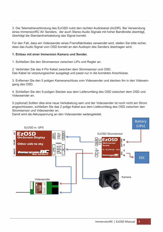
1. Einbau mit einer Immersion Kamera und Sender.
1. Schließen Sie den Stromsensor zwischen LiPo und Regler an.
2. Verbinden Sie das 4 Pin Kabel zwischen dem Stromsensor und OSD.Das Kabel ist verpolungssicher ausgelegt und passt nur in die korrekten Anschlüsse.
3. Entfernen Sie den 5 poligen Kameranschluss vom Videosender und stecken ihn in den Videoein-gang des OSD.
4. Schließen Sie den 5-poligen Stecker aus dem Lieferumfang des OSD zwischen dem OSD und Videosender an.
5.(optional) Sollten dies eine neue Verkabelung sein und der Videosender ist noch nicht am Strom angeschlossen, schließen Sie das 2 polige Kabel aus dem Lieferumfang des OSD zwischen den Stromsensor und Videosender an.Damit wird die Akkuspannung an den Videosender weitergeleitet.
EzOSD m. GPS
EzOSD Stromsensor
VideosenderKamera
ImmersionRC | EzOSD Manual 5
2. Installation without using the sensor board. When the sensor board is not required, the OSD may be powered directly from an unused connector on the R/C receiver. Cables to make this connection should be available from your local ImmersionRC distributor.
If the cable is not available, those handy with a soldering-iron could take two standard servo cables, remove the signal line (white/red/orange), connect the red wires together, black wires together, and on the OSD end of the cable, swap the red/black pins so that the red wire is on the +5v pin of the EzBUS, and the black wire is on the Gnd pin of the EzBUS.
Video Standard When provided with a standard composite video input, in either the PAL, or the NTSC format, the EzOSD will automatically switch to match the input format.
When powered up (usually for the first time), without a video input signal connected, the EzOSD will default to PAL mode.
To change this, power up the OSD with either the UP, or DOWN buttons pressed. The DOWN button will switch to PAL mode, the UP button will switch to NTSC.
Switch Functions The EzOSD is configured using three simple push-buttons. No need for a complex switch setup in your R/C transmitter, and no need for any external hardware.
Preferences Menu The center switch, marked MENU, will enter the simple preferences menu, shown below. All settings are accessible via a single menu.
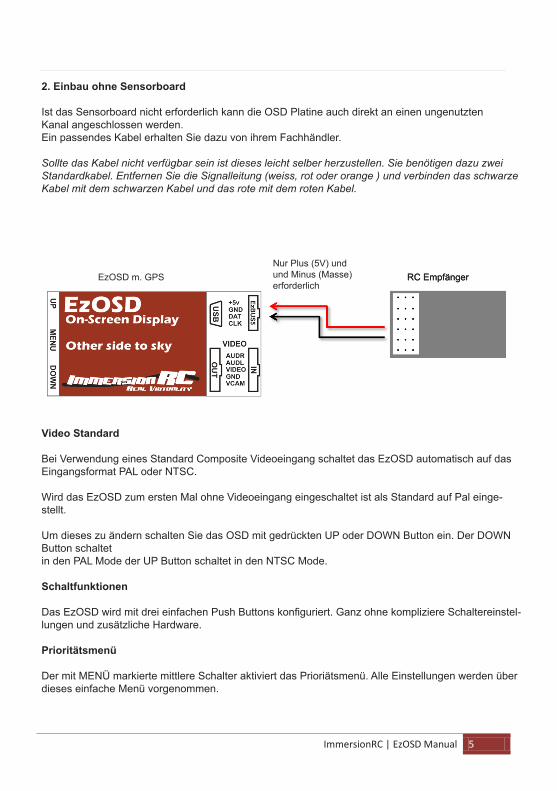
2. Einbau ohne Sensorboard
Ist das Sensorboard nicht erforderlich kann die OSD Platine auch direkt an einen ungenutzten Kanal angeschlossen werden.Ein passendes Kabel erhalten Sie dazu von ihrem Fachhändler.
Sollte das Kabel nicht verfügbar sein ist dieses leicht selber herzustellen. Sie benötigen dazu zwei Standardkabel. Entfernen Sie die Signalleitung (weiss, rot oder orange ) und verbinden das schwarze Kabel mit dem schwarzen Kabel und das rote mit dem roten Kabel.
Video Standard
Bei Verwendung eines Standard Composite Videoeingang schaltet das EzOSD automatisch auf das Eingangsformat PAL oder NTSC.
Wird das EzOSD zum ersten Mal ohne Videoeingang eingeschaltet ist als Standard auf Pal einge-stellt.
Um dieses zu ändern schalten Sie das OSD mit gedrückten UP oder DOWN Button ein. Der DOWN Button schaltet in den PAL Mode der UP Button schaltet in den NTSC Mode.
Schaltfunktionen
Das EzOSD wird mit drei einfachen Push Buttons konfiguriert. Ganz ohne kompliziere Schaltereinstel-lungen und zusätzliche Hardware.
Prioritätsmenü
Der mit MENÜ markierte mittlere Schalter aktiviert das Prioriätsmenü. Alle Einstellungen werden über dieses einfache Menü vorgenommen.
EzOSD m. GPSNur Plus (5V) und und Minus (Masse) erforderlich
RC Empfänger RC Empfänger
ImmersionRC | EzOSD Manual 6
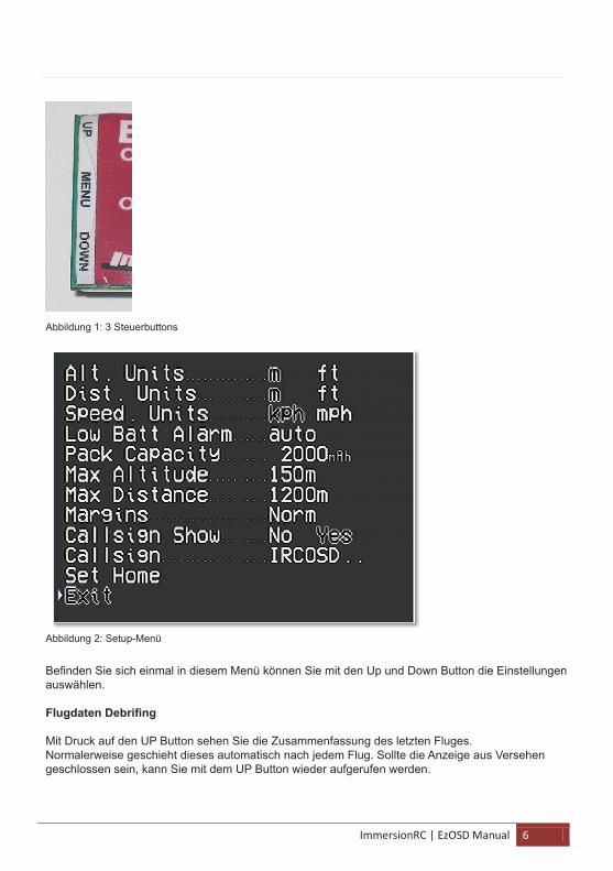
Figure 1: Simple 3-button UI
Figure 2: The setup menu
Once in the menu, the UP/DOWN button may be used to navigate between preferences, and the MENU button will modify the selected preference.
Show Flight Debriefing Pressing the UP button, will show a summary of the last flight.
Usually this is shown automatically after each flight, but if accidentally closed, the UP button will show it again.
Abbildung 1: 3 Steuerbuttons
Abbildung 2: Setup-Menü
Befinden Sie sich einmal in diesem Menü können Sie mit den Up und Down Button die Einstellungen auswählen.
Flugdaten Debrifing
Mit Druck auf den UP Button sehen Sie die Zusammenfassung des letzten Fluges.Normalerweise geschieht dieses automatisch nach jedem Flug. Sollte die Anzeige aus Versehen geschlossen sein, kann Sie mit dem UP Button wieder aufgerufen werden.
ImmersionRC | EzOSD Manual 7
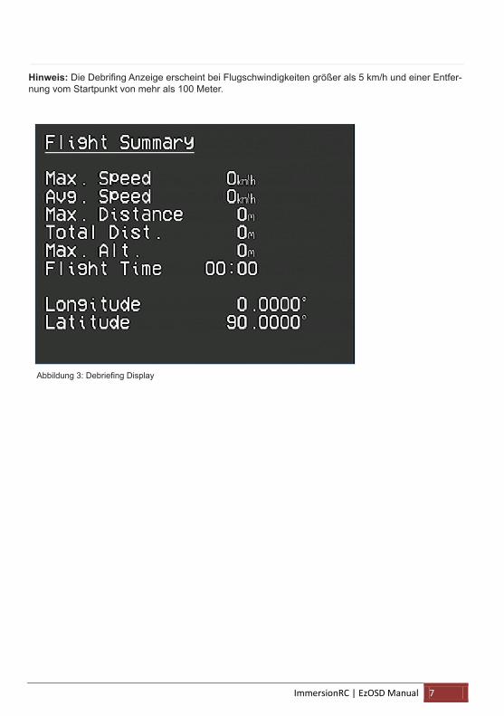
Note: the conditions for the debrief to appear after a flight are speed < 5km/h, and distance from launch < 100m.
Figure 3: Debriefing Display
Abbildung 3: Debriefing Display
Hinweis: Die Debrifing Anzeige erscheint bei Flugschwindigkeiten größer als 5 km/h und einer Entfer-nung vom Startpunkt von mehr als 100 Meter.
ImmersionRC | EzOSD Manual 8
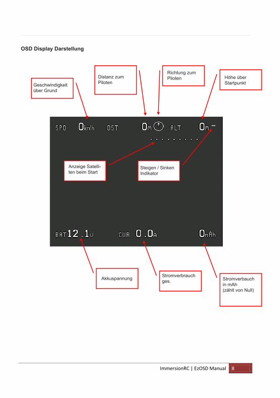
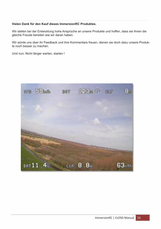
OSD Display Layout
Altitude, Above Launch Point
Direction to Pilot
Climb/Sink indicator
Battery Voltage Current Consumption
mAh Consumed (counts up from Zero)
Startup Satellite Count
Ground Speed
Distance (Ground) to Pilot
OSD Display Darstellung
Geschwindigkeit über Grund
Distanz zum Piloten
Höhe über Startpunkt
Richtung zum Piloten
Anzeige Satelli-ten beim Start
Steigen / Sinken Indikator
Stromverbauch in mAh (zählt von Null)
Stromverbrauch ges. Akkuspannung

ImmersionRC | EzOSD Manual 9
Alarms The EzOSD is equipped with 4 settings which define alarms. When an alarm triggers, the relevant on-screen readout will flash, to draw the pilot’s attention.
Figure 4: Alarms
The 4 alarms supported by the EzOSD are:
1. Low Battery
Defaults to ‘Auto’ mode, which assumes a LiPo flight pack. In this mode the number of cells is automatically detected.
The alarm will sound when the battery voltage drops down below 3.2v/cell.
2. Pack Capacity
While flying, the number of mAh (milliamp-hours) consumed from the battery is recorded. Once it reaches the trigger point set in the Pack Capacity alarm, the readout will flash, and it’s a good time to head home.
3. Max Altitude
While flying FPV it is easy to exceed local regulations regarding maximum permitted altitude for model flight. Set the Max. Altitude value to reflect these local regulations, and the altitude readout will flash when this altitude is exceeded. Remember: Altitude is always measured relative to the launch point in the EzOSD (AGL, vs. ASL).
4. Max. Distance
Set this alarm to warn when the plane is more than a pre-set distance from you.
Several of the worldwide modeling federations are starting to define rules for FPV flight on club fields.
These generally include the mention of a requirement to fly within visual range, or at least the visual range of the spotter pilot which should be monitoring your flight.
Set the Max. Distance alarm to warn you before your spotter starts panicing.
Also useful to warn before your R/C uplink looses control!
Alarme
Das EzOSD ist mit 4 möglichen Alarmen ausgestattet. Wird ein Alarm aktiv blinkt im Display die ent-sprechende OSD Anzeige.
Die 4 Alarmtypen des EzOSD sind:
1. Akkuspannung zu niedrig
Als Standard isrt dieser Alarm auf den Auto Mode eingestellt. In diesem Mode wird die Anzahl der Zellen automatisch erkannt. Der Alarm ertönt wenn die Akkuspannung unter 3.2 Volt per Zelle sinkt.
2. Akkukapazität
Während des Fluges werden die verbrauchten mAh aufgezeichnet. Ist der eingestellte Grenzwert erreicht ertönt der Alarm, die Anzeige blinkt und es ist an der Zeit nach Hause zu fliegen.
3. Maximale Höhe
Im FPV Betrieb kann es schnell passieren, dass Sie höher als für den Modellflug erlaubt fliegen. Pro-grammieren Sie die maximal erlaubte Höhe und der Alarm blinkt wenn Sie diese übersteigen.Bitte beachten: Die Höhe wird stets relativ zu dem Startpunkt dargestellt = Höhe über Grund und nicht Höhe über Meereshöhe (AGL vs. ASL).
4. Maximale Distanz
Dieser programmierbare Alarm warnt wenn das Modell eine voreingestellte Distanz überschreitet.Verschiedene internationale Modellflugorganisationen reglementieren den FPV Flug. Bestandteil dieser Regelung ist es im Bereich des Sichtfluges zu fliegen.Aktivieren Sie den Distanzalarm bevor der Spotter die Fluglage oder das Modell nicht mehr erkennen kann.
Ebenfalls kann es sinnvoll sein eine Reichweitenwarnung des RC System zu programmieren.
Abbildung 4: Alarme
ImmersionRC | EzOSD Manual 10
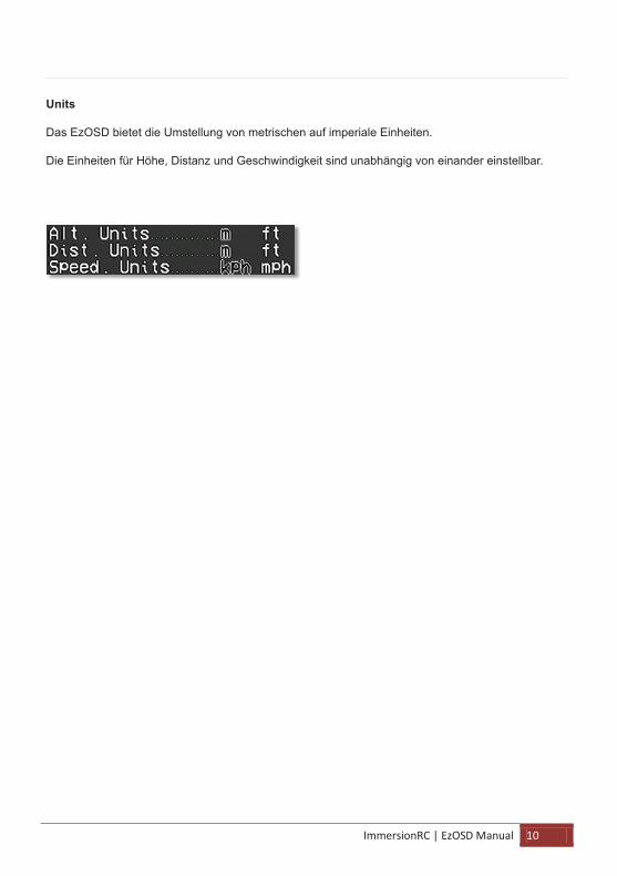
Units In order to accommodate our fellow pilots from lands where the metric system has not yet arrived, the EzOSD supports selectable units.
Units for Altitude, Distance, and Speed are all independently definable.
Units
Das EzOSD bietet die Umstellung von metrischen auf imperiale Einheiten.
Die Einheiten für Höhe, Distanz und Geschwindigkeit sind unabhängig von einander einstellbar.
ImmersionRC | EzOSD Manual 11
Flight The section of this manual which covers the use of the EzOSD is intentionally very short.
1. Bring Equipment to the field
2. Power up FPV equipment, and wait for ‘Acquiring Satellites’ to disappear (6 satellites required to fly)
3. Fly…
Telemetry, and Tracking Antenna The EzOSD transmits the position of the plane (Latitude/Longitude/Altitude) in a coded form, down the Right Audio channel.
This telemetry data may be used in several ways:
1) Replay a flight using the Immersion Player on a PC, and show the plane’s position, and track, in real time, in Google Earth™
2) Connect the audio output of the A/V receiver to one of ImmersionRC’s Antenna Tracking accessories. These will drive servos in a pan/tilt (or pan-only) antenna mount, to track the model as it moves around the sky.
The tracking antenna allows higher-gain, directional antennas to be used, and can be a great help where video transmitter power is limited.
Fliegen
Der Abschnitt der die Vorbereitung des EzOSD auf dem Flugplatz beschreibt ist erfreulicherweise sehr kurz.
1. Bringen Sie Ausrüstung auf das Feld.
2. Schalten Sie die FPV Ausrüstung ein warten darauf dass die Anzeige „Acquiring Satellites“ (Warte auf Satellitensignal) erlöscht. Zum Fliegen sind 6 Satellitensignale erforderlich.
3. Fliegen Sie.
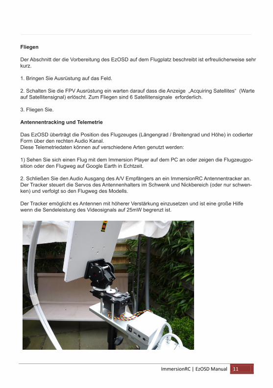
Antennentracking und Telemetrie
Das EzOSD überträgt die Position des Flugzeuges (Längengrad / Breitengrad und Höhe) in codierter Form über den rechten Audio Kanal.Diese Telemetriedaten können auf verschiedene Arten genutzt werden:
1) Sehen Sie sich einen Flug mit dem Immersion Player auf dem PC an oder zeigen die Flugzeugpo-sition oder den Flugweg auf Google Earth in Echtzeit.
2. Schließen Sie den Audio Ausgang des A/V Empfängers an ein ImmersionRC Antennentracker an. Der Tracker steuert die Servos des Antennenhalters im Schwenk und Nickbereich (oder nur schwen-ken) und verfolgt so den Flugweg des Modells.
Der Tracker emöglicht es Antennen mit höherer Verstärkung einzusetzen und ist eine große Hilfe wenn die Sendeleistung des Videosignals auf 25mW begrenzt ist.

ImmersionRC | EzOSD Manual 12
For further information on the ImmersionRC Antenna Tracker, see the documentation available on the ImmersionRC website.
Upgrading Firmware The EzOSD is equipped with a built-in USB port, with a standard connector, commonly found on most portable USB equipment (technical name is a mini-B).
Upgrading firmware requires no additional hardware, programmers, or returns to the factory. All that is required is a standard USB cable, and a utility which may be freely downloaded from the ImmersionRC website.
Figure 5: Standard Mini-B connector
Diagnostics, Q/A Q. The OSD is taking along time to acquire satellites, or is not very precise when flying
A. This is a common problem in our hobby. The GPS receiver is extremely sensitive, and is generally placed in close proximity to a powerful video transmitter. To solve this, keep the GPS as far from the video transmitter as possible.
2. Speed/Altitude not accurate when flying 3D
The GPS antenna is directional, and is similar to the patch antennas that we use commonly for video.
When throwing a plane around the sky, diving rapidly, flying inverted, etc. this directional antenna may well not be facing towards the satellites which provide its position. During these times, it is normal for the GPS readout, especially speed, and altitude, to be in-precise. When level flight is returned, the readings will correct themselves.
Weitere Informationen über den Immersion RC Antennen Tracker können Sie der ImmersionRC Webseite entnehmen.
Firmware Aktualisierungen
Zur Aktualisierung der Firmware ist kein spezieller Programmierbaustein oder eine Rücksendung an das Werk erforderlich.Das EzOSD ist mit einem eingebauten USB Anschluss (Mini B) versehen. So können Aktualisierungen einfach über das im Internet frei verfügbare Ifrontech Programm heruntergeladen werden.
Problemdiagnose, Fragen & Antworten
Frage: Es dauert sehr lange bis das OSD eine Satellitenverbindung hat oder die Anzeige ist unpräzise.
Antwort: Diese Problem ist in unserem Hobby bekannt. Der GPS Empfänger ist extrem empfindlich und befin-det sich in unmittelbarer Nähe zum Videosender. Um diese Problem zu lösen positionieren Sie das GPS soweit weg vom Videosender wie möglich.
Frage: Höhe / Geschwindigkeit wird bei dem 3D Flug nicht korrekt dargestellt.
Antwort: Die GPS Antenne empfängt direktional und ist mit den meisten Patchantennen die im Videobereich verwendet werden zu vergleichen.
Bewegt sich das Flugzeug im Kunstflug am Himmel kann aufgrund dieser Auslegung der Kontakt zu den Satelliten behindert sein und die GPS Angabe zu Geschwindigkeit und Höhe unpräzise. Kehrt das Flugzeug in seine normale Fluglage zurück, korrigieren sich diese Informationen von alleine.
Abbildung 5: Standard Mini-B Anschluss

ImmersionRC | EzOSD Manual 13
Warnings! If tempted to remove the heatshrink , and relocate the GPS (not recommended), please take great care when removing the GPS from its sticky insulating foam. If pulled straight off, the foam will pull the metal screen from the body of the GPS, and destroy it.
Either slide a sharp blade (carefully) between the gps, and the foam, or use a twisting motion to remove it.
Note that damaged caused by removing the GPS is not covered under warranty!
Warnung!
Sollten Sie vorhaben den Schrumpfschlauch zu entfernen und das GPS neu zu positionieren (Wir empfehlen dieses nicht) müssen Sie bei dem Entfernen der GPS Platine vom Schaumstoff größte Vorsicht walten lassen. Sollten Sie diese gerade nach oben abziehen, löst der Schaumstoff den Me-tallmantel vom GPS Gehäuse und zerstört es damit. Trennen Sie die Schaumverbindung unter dem GPS mit einer scharfen Klinge oder lösen diese vor-sichtig durch drehen.
Bitte beachten Sie, dass Schäden die durch das Entfernen des GPS entstanden sind nicht durch die Garantie gedeckt werden!.
ImmersionRC | EzOSD Manual 14
+
-
-
+
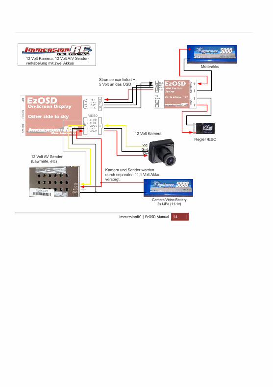
12v Camera, 12v A/V Transmitter CablingDual-Battery
VidGnd12v
VID12v
AUDGND
+
-
Motor Battery
Camera/Video Battery3s LiPo (11.1v)
ESC
12v A/V Tx (Lawmate, etc.)
12v Camera
Current Sensor supplies+5v power to OSD
Camera and Tx poweredby separate 11.1v battery
12 Volt Kamera, 12 Volt A/V Sender-verkabelung mit zwei Akkus
Kamera und Sender werden durch separaten 11,1 Volt Akku versorgt.
12 Volt AV Sender (Lawmate, etc)
12 Volt KameraRegler /ESC
Motorakku
Stromsensor liefert + 5 Volt an das OSD

ImmersionRC | EzOSD Manual 15
ImmersionRC | EzOSD Manual 16
Thank You… Thank you for purchasing this ImmersionRC product.
We take great pride in the design of our products, and hope that they give you as much pleasure as they have given us.
Please don’t hesitate to feed back any comments/suggestions/complaints to us, we do listen, and any feedback will help in perfecting our products in the future.
Now, what are you waiting for, Go Fly!
Vielen Dank für den Kauf dieses ImmersionRC Produktes.
Wir stellen bei der Entwicklung hohe Ansprüche an unsere Produkte und hoffen, dass sie Ihnen die gleiche Freude bereiten wie wir daran haben.
Wir würde uns über ihr Feedback und ihre Kommentare freuen, dienen sie doch dazu unsere Produk-te noch besser zu machen.
Und nun: Nicht länger warten, starten !