Embed Size (px)
Citation preview
FRAUNHOFER- INSTITUT FÜR GRENZFLÄCHEN- UND B IOVERFAHRENSTECHNIK IGB
Guideline: Vacuum sewer systems
Guideline: Vacuum sewer systems
December 2016
Dr.-Ing. Marius Mohr, Jan Iden, Marc Beckett
Fraunhofer-Institut für Grenzflächen- und Bioverfahrenstechnik IGB Nobelstraße 12 70569 Stuttgart
Fraunhofer IGB Vacuum sewer system GIZ GmbH I | IV
Content
1 Introduction ........................................................................................................... 1
2 Technology of vacuum sewer systems ................................................................ 4 2.1 Concept ................................................................................................................... 4 2.2 Components and their tasks..................................................................................... 5 2.3. Manufacturers / System providers .......................................................................... 21
3. Investment costs ................................................................................................. 25
4. Operation and Maintenance costs ..................................................................... 29 4.1. Electricity costs ....................................................................................................... 30 4.2. Personnel cost ........................................................................................................ 31 4.3. Material cost .......................................................................................................... 33 4.4. Other costs ............................................................................................................ 34
5. Durability (life span/life cycle) ........................................................................... 35
6. Operational and maintenance skills required .................................................. 38 6.1. Normal and preventive maintenance ...................................................................... 38 6.2. Emergency maintenance ........................................................................................ 41 6.3. Record keeping ...................................................................................................... 42 6.4. O&M manual ......................................................................................................... 44 6.5. Spare parts ............................................................................................................. 45 6.6. Summary................................................................................................................ 45
7. User friendliness .................................................................................................. 46
8. Cases for application ........................................................................................... 49
9. Reference projects ............................................................................................... 50
10 Vacuum sewers as part of an integrated water management concept ......... 54
11. Critical issues for building and operating a vacuum sewer system ............... 61 11.1. Pros and Cons ........................................................................................................ 61 11.2. Critical features ...................................................................................................... 62 11.2.1. General .................................................................................................................. 62 11.2.2. Collection pits ........................................................................................................ 63 11.2.3. Interface valve ........................................................................................................ 64 11.2.4. Vacuum lines / network .......................................................................................... 64 11.2.5. Vacuum station ...................................................................................................... 65
12. Summary & conclusion ....................................................................................... 67
References ........................................................................................................................... 69
Annex 1: ............................................................................................................................ 73
Annex 2: ............................................................................................................................ 76
Annex 3: ............................................................................................................................ 78
Annex 4: ............................................................................................................................ 79
Fraunhofer IGB Vacuum sewer system GIZ GmbH II | IV
List of Figures
Figure 1: Overview of a vacuum sewer system involving the vacuum valve unit at the valve pits, vacuum mains and the central vacuum station [8] 5
Figure 2: Left: Schematic layout of a collection pit with vacuum valve ; Right: prefabricated collection pit . 6
Figure 3: Vacuum valve [12] 8
Figure 4: Valve pit with two interface valves to accommodate higher discharges [5]. 9
Figure 5:Hierachy of pipes within a vacuum sewer system and the corresponding pipe diameters [5]. 10
Figure 6: Saw-tooth profile of a vacuum sewer line [5] 11
Figure 7: Filling material of excavation for a vacuum line. Trenching material in the top layer, followed by a layer of gravel and a liner which separates the gravel from the sand [7] 13
Figure 8: Division valve with gauge tap at a vacuum main [5] 13
Figure 9: Service lateral connection [1]. Note that the diameter of der service lateral is equal to the diameter of the interface valve (= 3 inch = 7.6 cm). Pipes should be joined at the upper part of the receiving pipe at an angle of 60° 15
Figure 10: The vacuum station can be designed with high flexibility. Anything from prefabricated houses to underground stations which are integrated into the environment exists [12]. 16
Figure 11: All vacuum pumps are connected to the same pipe. The pumps are setup in parallel. 17
Figure 12: Layout of a vacuum station with the collection tank in the ground and the sewage pumps outside of the tank. The vacuum reservoir tank is integrated into the collection tank in most layouts[5, 14] 18
Figure 13: Biofilter used for odour control from a vacuum tank. Right: woodchips are a common filling material [1] 19
Figure 14:Vacuum station with external power connection for power supply in case of blackouts [12] 20
Figure 15: Comparison of elements most susceptible to failure in different sewer systems; diagram based on [26] 47
Figure 16: Reconditioning time for different sewer systems [26] 48
Figure 17: Number of vacuum sewer projects implemented by ROEDIGER and AIRVAC (now Aqseptence Group) between 1973 and 2008 [28] 51
Figure 18: Vacuum pipe installed in existing channels; the PE pipe is attached to the wall of the channel [46]. 54
Fraunhofer IGB Vacuum sewer system GIZ GmbH III | IV
Figure 19: Layout of the sanitation and reuse concept in Outapi, Namibia [39]. 56
Figure 20: Schematic overview on how water management was designed in DEUS 21 with vacuum sewers being the selected technology for wastewater conveyance [40] 57
Figure 21: Left: Garbage disposal unit in kitchen sink; Right: Vacuum toilet [1] 58
Figure 22: Black water and grey water are separately collected in separate collection sumps within the same collection pit of the vacuum system [43] 59
Figure 23: Vacuum station in Böblingen-Dagersheim 79
Figure 24: Collection pit in Waldsee. Access is restricted due to construction of wooden terrace. Access to the collection pit should be kept clear. 79
Figure 25: Vacuum tank placed in hedge in Waldsee. The components of the vacuum station have been integrated in the hedge instead of a building. 80
Figure 26: Collection pit with vacuum valve in Walldorf. The collection pit is located on a drivable road made of concrete. Respective measures were implemented. 80
Figure 27: Vacuum tank constructed underground at the vacuum station in Walldorf. The relevant pipe connections and sensor provisions are located at the top of the tank. 81
Figure 28: Biofilter with additional aeration pipe at the vacuum station in Walldorf. Plants grow on the filter material. 81
Figure 29: Vacuum tank at the vacuum station in Knittlingen. The wastewater pumps are placed outside the tank. 82
Fraunhofer IGB Vacuum sewer system GIZ GmbH IV | IV
List of Tables
Table 1: Pipe diameters and the relation to maximum flow per minute and maximum number of served households (data from [3]) 11
Table 2: Approximate investment costs for selected components of vacuum sewers under conditions in Germany 26
Table 3: Cost of PE and PVC-U pipes per meter for different diameters under German market conditions; note that material for PE is more expensive but the prices for PVC pipes include solvent welding (not included for PE) and are thus higher [18] 27
Table 4: Costs which can vary significantly by region and affect the investment costs 28
Table 5: Selected tasks and their approximate duration (values based on experiences in Germany and the USA) 32
Table 6: Approximate material costs for selected components of vacuum sewers 34
Table 7: Potential other costs related to O&M of vacuum sewers 35
Table 8: Durability of major components of a vacuum sewer network [2, 10, 12, 12, 18, 23, 24] 36
Table 9: Overview of normal and preventive maintenance tasks and their frequencies [21] 39
Table 10: List of relevant O&M records [21] 43
Table 11: List of O&M cost records 44
Table 12: Typical information included in O&M manuals 44
Table 13: Summary of advantages and disadvantages of vacuum sewers 61
Fraunhofer IGB Vacuum sewer systems GIZ GmbH 1 | 82
Introduction 1
Introduction
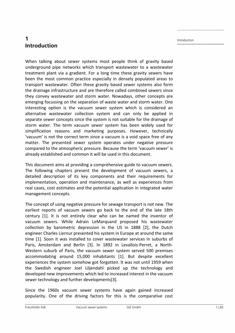
When talking about sewer systems most people think of gravity based underground pipe networks which transport wastewater to a wastewater treatment plant via a gradient. For a long time these gravity sewers have been the most common practice especially in densely populated areas to transport wastewater. Often these gravity based sewer systems also form the drainage infrastructure and are therefore called combined sewers since they convey wastewater and storm water. Nowadays, other concepts are emerging focussing on the separation of waste water and storm water. One interesting option is the vacuum sewer system which is considered an alternative wastewater collection system and can only be applied in separate sewer concepts since the system is not suitable for the drainage of storm water. The term vacuum sewer system has been widely used for simplification reasons and marketing purposes. However, technically ‘vacuum’ is not the correct term since a vacuum is a void space free of any matter. The presented sewer system operates under negative pressure compared to the atmospheric pressure. Because the term ‘vacuum sewer’ is already established and common it will be used in this document.
This document aims at providing a comprehensive guide to vacuum sewers. The following chapters present the development of vacuum sewers, a detailed description of its key components and their requirements for implementation, operation and maintenance, as well as experiences from real cases, cost estimates and the potential application in integrated water management concepts.
The concept of using negative pressure for sewage transport is not new. The earliest reports of vacuum sewers go back to the end of the late 18th century [1]. It is not entirely clear who can be named the inventor of vacuum sewers. While Adrain LeMarquand proposed his wastewater collection by barometric depression in the US in 1888 [2], the Dutch engineer Charles Liernur presented his system in Europe at around the same time [1]. Soon it was installed to cover wastewater services in suburbs of Paris, Amsterdam and Berlin [3]. In 1892 in Levallois‐Perret, a North‐Western suburb of Paris, the vacuum sewer system served 500 premises accommodating around 15,000 inhabitants [1]. But despite excellent experiences the system somehow got forgotten. It was not until 1959 when the Swedish engineer Joel Liljendahl picked up the technology and developed new improvements which led to increased interest in the vacuum sewer technology and further developments[3].
Since the 1960s vacuum sewer systems have again gained increased popularity. One of the driving factors for this is the comparative cost
Fraunhofer IGB Vacuum sewer systems GIZ GmbH 2 | 82
Introduction
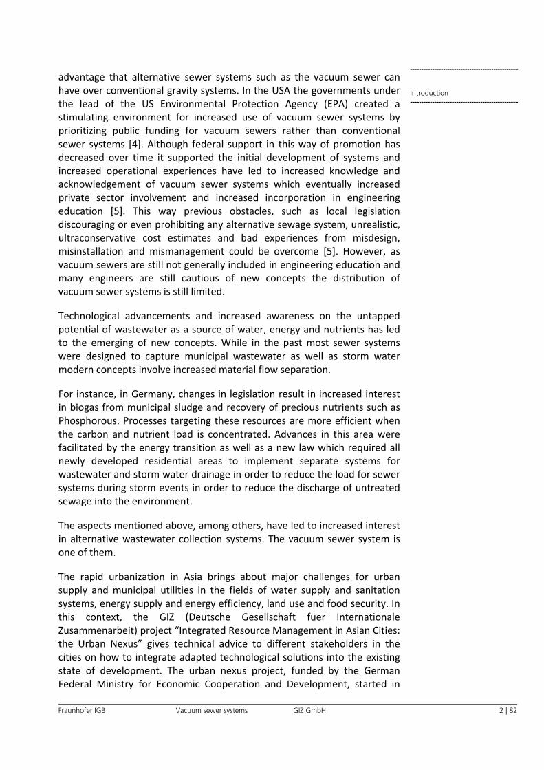
advantage that alternative sewer systems such as the vacuum sewer can have over conventional gravity systems. In the USA the governments under the lead of the US Environmental Protection Agency (EPA) created a stimulating environment for increased use of vacuum sewer systems by prioritizing public funding for vacuum sewers rather than conventional sewer systems [4]. Although federal support in this way of promotion has decreased over time it supported the initial development of systems and increased operational experiences have led to increased knowledge and acknowledgement of vacuum sewer systems which eventually increased private sector involvement and increased incorporation in engineering education [5]. This way previous obstacles, such as local legislation discouraging or even prohibiting any alternative sewage system, unrealistic, ultraconservative cost estimates and bad experiences from misdesign, misinstallation and mismanagement could be overcome [5]. However, as vacuum sewers are still not generally included in engineering education and many engineers are still cautious of new concepts the distribution of vacuum sewer systems is still limited.
Technological advancements and increased awareness on the untapped potential of wastewater as a source of water, energy and nutrients has led to the emerging of new concepts. While in the past most sewer systems were designed to capture municipal wastewater as well as storm water modern concepts involve increased material flow separation.
For instance, in Germany, changes in legislation result in increased interest in biogas from municipal sludge and recovery of precious nutrients such as Phosphorous. Processes targeting these resources are more efficient when the carbon and nutrient load is concentrated. Advances in this area were facilitated by the energy transition as well as a new law which required all newly developed residential areas to implement separate systems for wastewater and storm water drainage in order to reduce the load for sewer systems during storm events in order to reduce the discharge of untreated sewage into the environment.
The aspects mentioned above, among others, have led to increased interest in alternative wastewater collection systems. The vacuum sewer system is one of them.
The rapid urbanization in Asia brings about major challenges for urban supply and municipal utilities in the fields of water supply and sanitation systems, energy supply and energy efficiency, land use and food security. In this context, the GIZ (Deutsche Gesellschaft fuer Internationale Zusammenarbeit) project “Integrated Resource Management in Asian Cities: the Urban Nexus” gives technical advice to different stakeholders in the cities on how to integrate adapted technological solutions into the existing state of development. The urban nexus project, funded by the German Federal Ministry for Economic Cooperation and Development, started in
Fraunhofer IGB Vacuum sewer systems GIZ GmbH 3 | 82
Introduction
April 2013. The second phase of the project started in 2016. This report has been developed in the context of this project and shall inform decision makers and technical experts in cities about the characteristics of vacuum sewer systems.
Fraunhofer IGB Vacuum sewer systems GIZ GmbH 4 | 82
Technology of vacuum sewer
systems
2 Technology of vacuum sewer systems
2.1 Concept
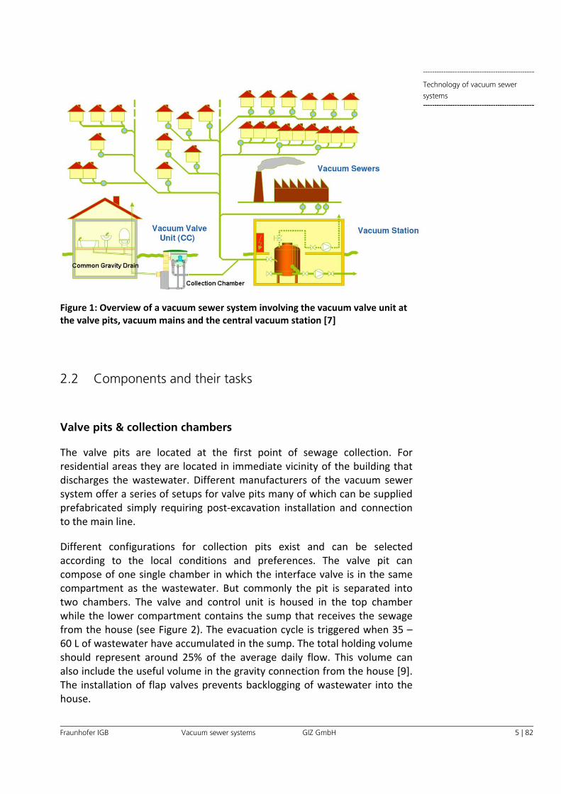
A vacuum sewer system works in a similar way as water distribution systems. The only difference is the direction of flow. While water supply uses positive pressure to ‘push’ the water from the treatment plant to the point of consumption, vacuum sewers use negative pressure to ‘draw’ the wastewater from the point of generation to the wastewater treatment plant [6, 6]. In contrast to conventional gravity flow or pressured sewer systems vacuum sewers use differential air pressure to transport wastewater which is generated by vacuum pumps located at the vacuum station, a centralized unit and in most designs the only point of electricity consumption. The pumps draw in atmospheric air through specific air inlets located at the wastewater collection points. The air inlets are attached to valve pits which form the point of collection for wastewater from the surrounding buildings. Besides the collection chamber (sump) for wastewater the valve pits contain the control units and the interface valves which form the interface between the negative pressure in the system and the atmospheric pressure in the valve pit. The valve is usually closed and opens after the control unit signals that a predetermined amount of sewage has accumulated in the sump. The pressure difference between the network and the valve pit causes the water to be sucked into the vacuum main where it is transported to the collection tank located at the central vacuum station. The drawn air expands under the negative pressure conditions and drives the transport mechanism. On the way to the collection tank at the vacuum station the transported wastewater temporarily comes to rest at depressions within the profile of the pipe network due to friction and weight forces. This way the wastewater is transported in frequent intervals until it reaches the collection tank at the vacuum station which contains the pumps and control equipment. From here pumps, usually pressured sewage pumps, forward the wastewater towards the wastewater treatment plant. A layout of a typical vacuum sewer network is shown in Figure 1.
Fraunhofer IGB Vacuum sewer systems GIZ GmbH 5 | 82
Technology of vacuum sewer
systems
Figure 1: Overview of a vacuum sewer system involving the vacuum valve unit at the valve pits, vacuum mains and the central vacuum station [7]
2.2 Components and their tasks
Valve pits & collection chambers
The valve pits are located at the first point of sewage collection. For residential areas they are located in immediate vicinity of the building that discharges the wastewater. Different manufacturers of the vacuum sewer system offer a series of setups for valve pits many of which can be supplied prefabricated simply requiring post‐excavation installation and connection to the main line.
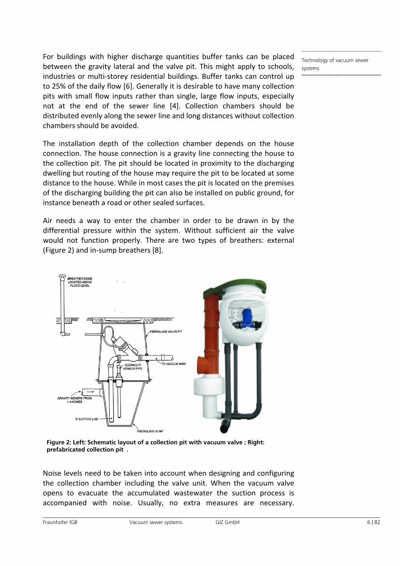
Different configurations for collection pits exist and can be selected according to the local conditions and preferences. The valve pit can compose of one single chamber in which the interface valve is in the same compartment as the wastewater. But commonly the pit is separated into two chambers. The valve and control unit is housed in the top chamber while the lower compartment contains the sump that receives the sewage from the house (see Figure 2). The evacuation cycle is triggered when 35 – 60 L of wastewater have accumulated in the sump. The total holding volume should represent around 25% of the average daily flow. This volume can also include the useful volume in the gravity connection from the house [9]. The installation of flap valves prevents backlogging of wastewater into the house.
Fraunhofer IGB Vacuum sewer systems GIZ GmbH 6 | 82
Technology of vacuum sewer
systems
For buildings with higher discharge quantities buffer tanks can be placed between the gravity lateral and the valve pit. This might apply to schools, industries or multi‐storey residential buildings. Buffer tanks can control up to 25% of the daily flow [6]. Generally it is desirable to have many collection pits with small flow inputs rather than single, large flow inputs, especially not at the end of the sewer line [4]. Collection chambers should be distributed evenly along the sewer line and long distances without collection chambers should be avoided.
The installation depth of the collection chamber depends on the house connection. The house connection is a gravity line connecting the house to the collection pit. The pit should be located in proximity to the discharging dwelling but routing of the house may require the pit to be located at some distance to the house. While in most cases the pit is located on the premises of the discharging building the pit can also be installed on public ground, for instance beneath a road or other sealed surfaces.
Air needs a way to enter the chamber in order to be drawn in by the differential pressure within the system. Without sufficient air the valve would not function properly. There are two types of breathers: external (Figure 2) and in‐sump breathers [8].
Noise levels need to be taken into account when designing and configuring the collection chamber including the valve unit. When the vacuum valve opens to evacuate the accumulated wastewater the suction process is accompanied with noise. Usually, no extra measures are necessary.
Figure 2: Left: Schematic layout of a collection pit with vacuum valve ; Right: prefabricated collection pit .
Fraunhofer IGB Vacuum sewer systems GIZ GmbH 7 | 82
Technology of vacuum sewer
systems
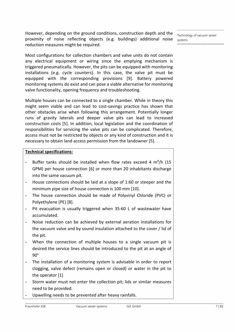
However, depending on the ground conditions, construction depth and the proximity of noise reflecting objects (e.g. buildings) additional noise reduction measures might be required.
Most configurations for collection chambers and valve units do not contain any electrical equipment or wiring since the emptying mechanism is triggered pneumatically. However, the pits can be equipped with monitoring installations (e.g. cycle counters). In this case, the valve pit must be equipped with the corresponding provisions [9]. Battery powered monitoring systems do exist and can pose a viable alternative for monitoring valve functionality, opening frequency and troubleshooting.
Multiple houses can be connected to a single chamber. While in theory this might seem viable and can lead to cost‐savings practice has shown that other obstacles arise when following this arrangement. Potentially longer runs of gravity laterals and deeper valve pits can lead to increased construction costs [5]. In addition, local legislation and the coordination of responsibilities for servicing the valve pits can be complicated. Therefore, access must not be restricted by objects or any kind of construction and it is necessary to obtain land access permission from the landowner [5].
Technical specifications:
- Buffer tanks should be installed when flow rates exceed 4 m³/h (15
GPM) per house connection [6] or more than 20 inhabitants discharge
into the same vacuum pit.
- House connections should be laid at a slope of 1:60 or steeper and the
minimum pipe size of house connection is 100 mm [10].
- The house connection should be made of Polyvinyl Chloride (PVC) or
Polyethylene (PE) [8].
- Pit evacuation is usually triggered when 35‐60 L of wastewater have
accumulated.
- Noise reduction can be achieved by external aeration installations for
the vacuum valve and by sound insulation attached to the cover / lid of
the pit.
- When the connection of multiple houses to a single vacuum pit is
desired the service lines should be introduced to the pit at an angle of
90°
- The installation of a monitoring system is advisable in order to report
clogging, valve defect (remains open or closed) or water in the pit to
the operator [1]
- Storm water must not enter the collection pit; lids or similar measures
need to be provided.
- Upwelling needs to be prevented after heavy rainfalls.
Fraunhofer IGB Vacuum sewer systems GIZ GmbH 8 | 82
Technology of vacuum sewer
systems
- The collection pit needs to be made of corrosion proof material (e.g.
polyethylene).
- The inner surface of the chamber should be smooth to allow for a self‐
cleaning discharge [9].
- Flap valves need to be installed to prevent backlogging.
- Valve pits in areas that are subject to flooding must be equipped with measures that allow aeration even when the valve pit is submerged.
Interface Valve Unit
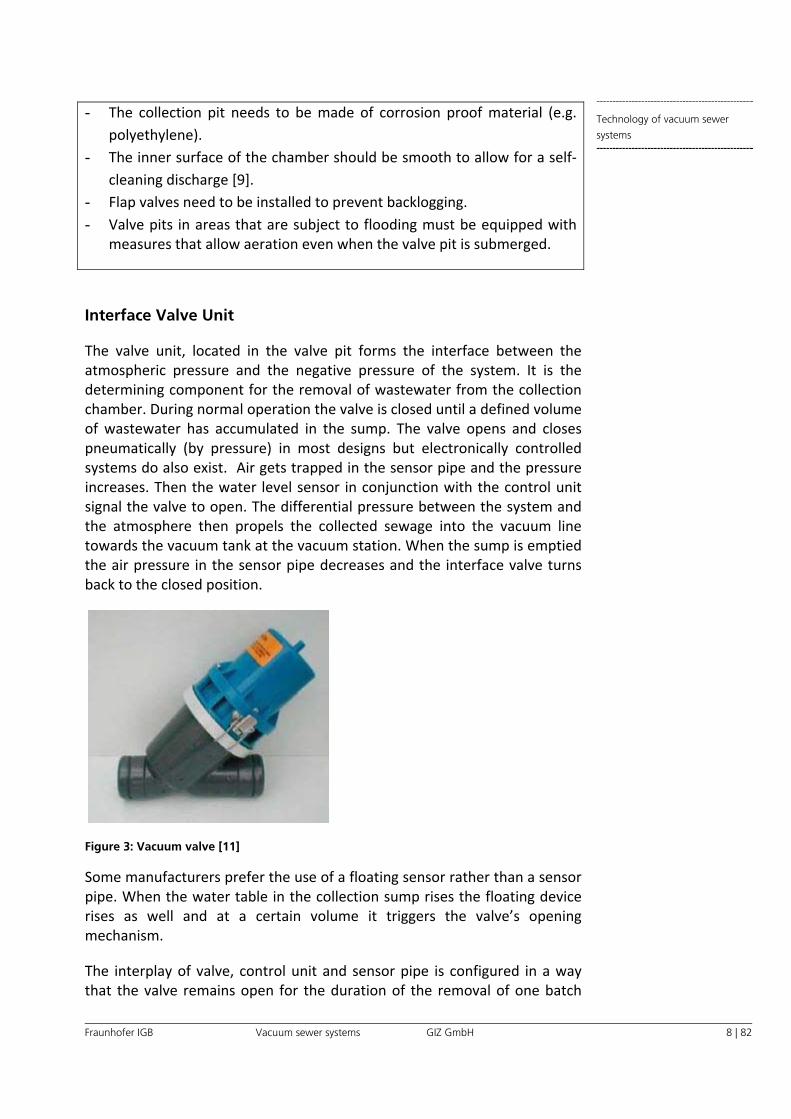
The valve unit, located in the valve pit forms the interface between the atmospheric pressure and the negative pressure of the system. It is the determining component for the removal of wastewater from the collection chamber. During normal operation the valve is closed until a defined volume of wastewater has accumulated in the sump. The valve opens and closes pneumatically (by pressure) in most designs but electronically controlled systems do also exist. Air gets trapped in the sensor pipe and the pressure increases. Then the water level sensor in conjunction with the control unit signal the valve to open. The differential pressure between the system and the atmosphere then propels the collected sewage into the vacuum line towards the vacuum tank at the vacuum station. When the sump is emptied the air pressure in the sensor pipe decreases and the interface valve turns back to the closed position.
Figure 3: Vacuum valve [11]
Some manufacturers prefer the use of a floating sensor rather than a sensor pipe. When the water table in the collection sump rises the floating device rises as well and at a certain volume it triggers the valve’s opening mechanism.
The interplay of valve, control unit and sensor pipe is configured in a way that the valve remains open for the duration of the removal of one batch
Fraunhofer IGB Vacuum sewer systems GIZ GmbH 9 | 82
Technology of vacuum sewer
systems
volume of wastewater. This includes sufficient time to simultaneously or successively draw in wastewater and air in order to achieve an adequate air/liquid ratio. The air/liquid ratio is a very important parameter heavily affecting the efficiency and profitability of the system [11]. The valve can be adjusted according to the desired air/liquid ratios to optimize the removal process. Air/liquid ratio depends on the position of the valve within the network.
In the event of power blackouts (e.g. at the vacuum station) or other system failures the valve must remain closed in order to avoid too much wastewater within the vacuum mains, in case remaining system pressure is too low to transport the wastewater to the collection tank.
Most problems affecting vacuum sewers are related to failures in the opening/closing mechanism of the valve. When the valve fails to open this may result in the accumulation of wastewater in the collection chamber and potentially backup into the building [12]. Thus, precautions need to be taken such as regular checks of the valves. On the contrary, when the valve fails to close the whole system has reduced vacuum which eventually affects the performance of the entire system and increases the electricity consumption.
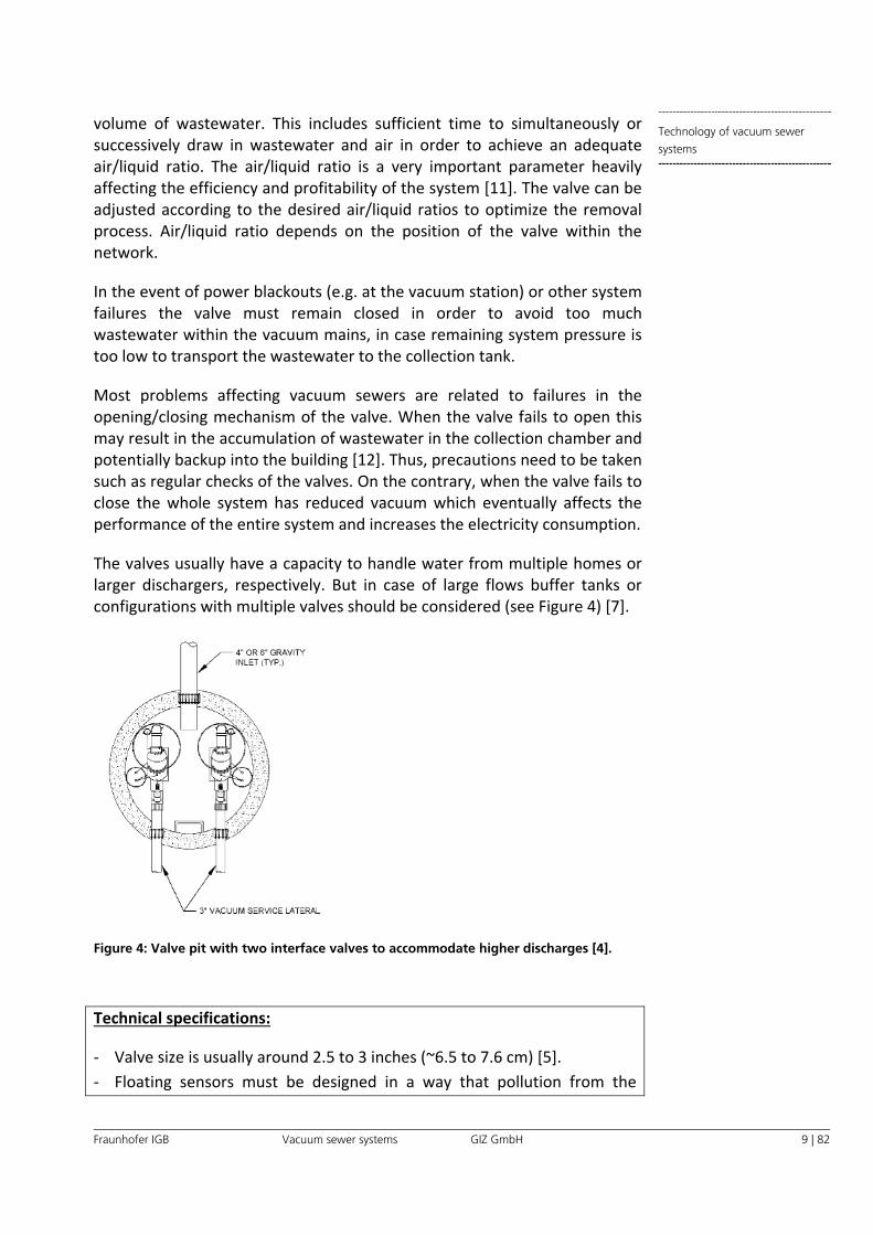
The valves usually have a capacity to handle water from multiple homes or larger dischargers, respectively. But in case of large flows buffer tanks or configurations with multiple valves should be considered (see Figure 4) [7].
Figure 4: Valve pit with two interface valves to accommodate higher discharges [4].
Technical specifications:
‐ Valve size is usually around 2.5 to 3 inches (~6.5 to 7.6 cm) [5].
‐ Floating sensors must be designed in a way that pollution from the
Fraunhofer IGB Vacuum sewer systems GIZ GmbH 10 | 82
Technology of vacuum sewer
systems
contact with wastewater does not affect the functionality of the sensor.
‐ Air/ liquid ratio varies between 3:1 – 15:1; the ratio is higher for valves
located further away from the vacuum station [11].
‐ All components that can come into contact with wastewater, such as the
water level gauge (sensor pipe), or even the valve itself, must be
resistant against wastewater [9].
‐ The opening mechanism should be enabled if local pressure is below
minus 0.15 bar [3, 9]; if the sump is more than 1 m below the valve the
threshold should be set to minus 0.35 bar [3].
‐ If flow‐rate exceeds 8.2 m³/h (30 GPM) buffer tanks or multiple valves
should be considered [7].
Vacuum mains and pipe network
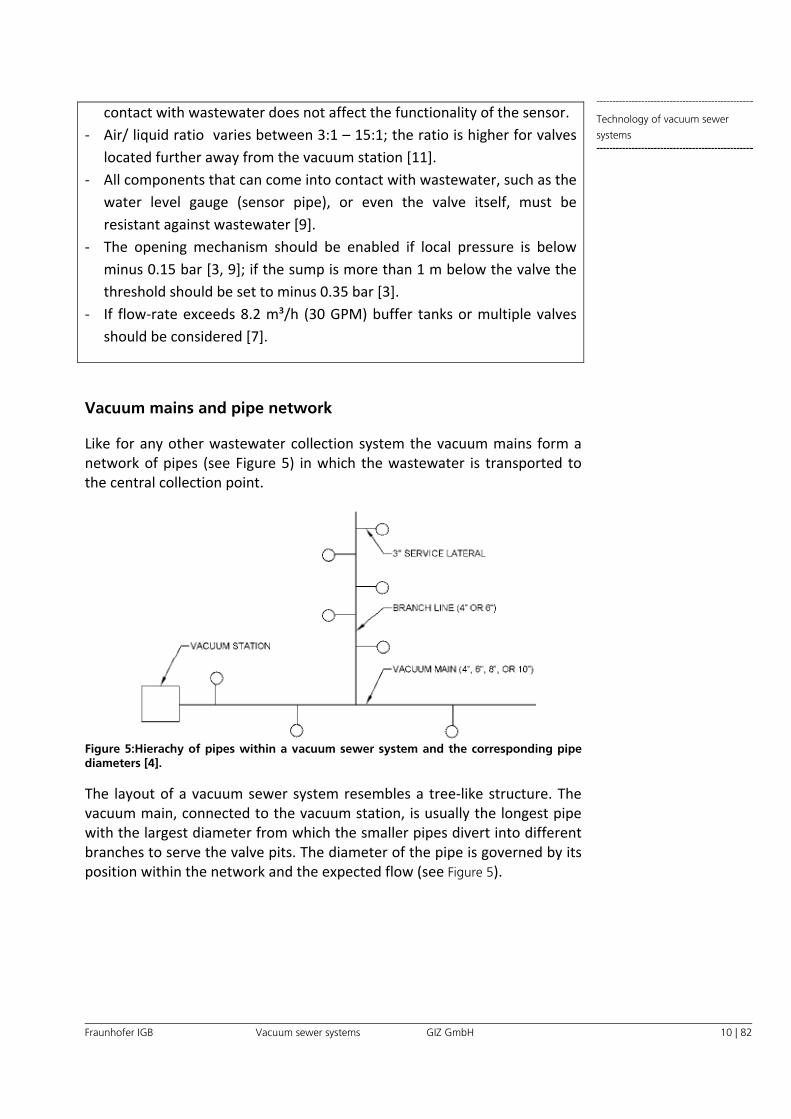
Like for any other wastewater collection system the vacuum mains form a network of pipes (see Figure 5) in which the wastewater is transported to the central collection point.
Figure 5:Hierachy of pipes within a vacuum sewer system and the corresponding pipe diameters [4].
The layout of a vacuum sewer system resembles a tree‐like structure. The vacuum main, connected to the vacuum station, is usually the longest pipe with the largest diameter from which the smaller pipes divert into different branches to serve the valve pits. The diameter of the pipe is governed by its position within the network and the expected flow (see Figure 5).
Fraunhofer IGB Vacuum sewer systems GIZ GmbH 11 | 82
Technology of vacuum sewer
systems
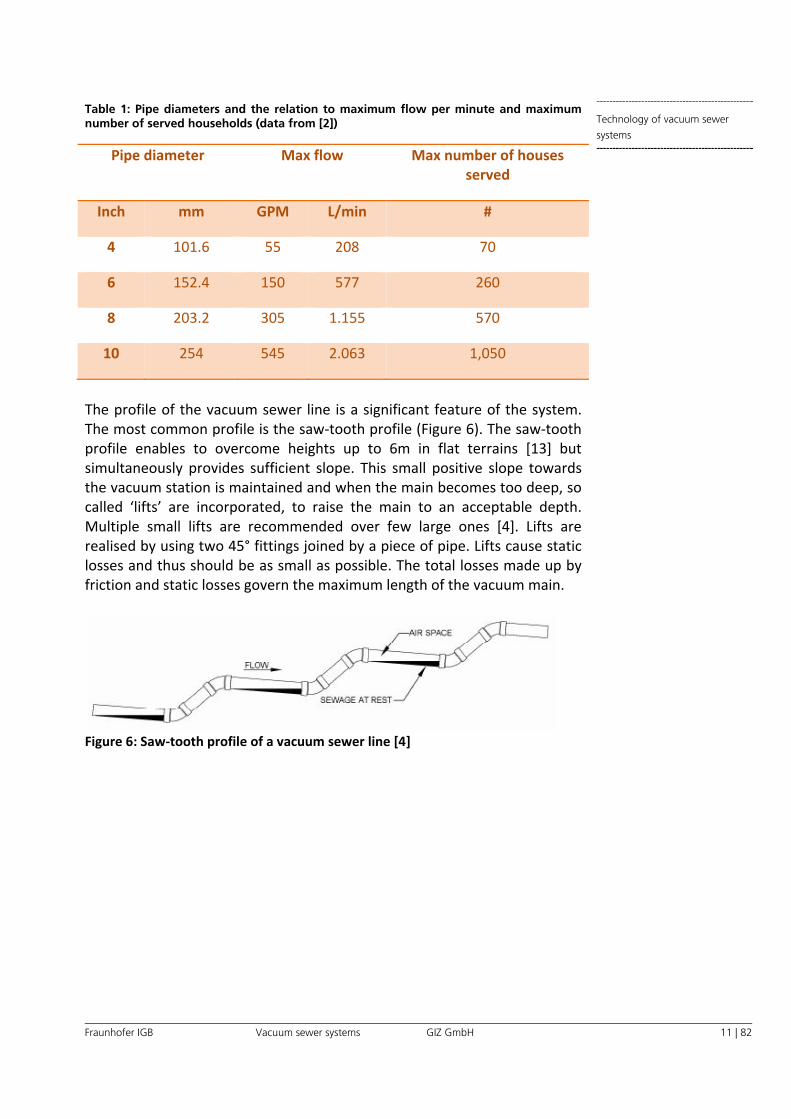
Table 1: Pipe diameters and the relation to maximum flow per minute and maximum number of served households (data from [2])
Pipe diameter Max flow Max number of houses served
Inch mm GPM L/min #
4 101.6 55 208 70
6 152.4 150 577 260
8 203.2 305 1.155 570
10 254 545 2.063 1,050
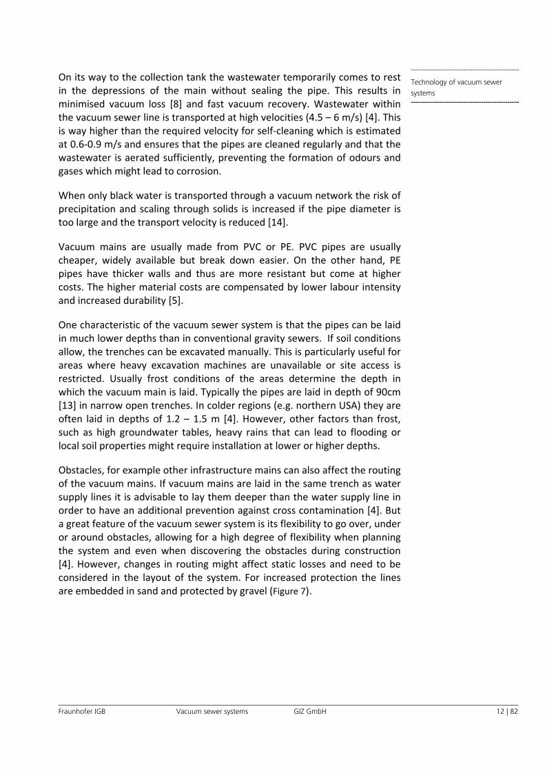
The profile of the vacuum sewer line is a significant feature of the system. The most common profile is the saw‐tooth profile (Figure 6). The saw‐tooth profile enables to overcome heights up to 6m in flat terrains [13] but simultaneously provides sufficient slope. This small positive slope towards the vacuum station is maintained and when the main becomes too deep, so called ‘lifts’ are incorporated, to raise the main to an acceptable depth. Multiple small lifts are recommended over few large ones [4]. Lifts are realised by using two 45° fittings joined by a piece of pipe. Lifts cause static losses and thus should be as small as possible. The total losses made up by friction and static losses govern the maximum length of the vacuum main.
Figure 6: Saw‐tooth profile of a vacuum sewer line [4]
Fraunhofer IGB Vacuum sewer systems GIZ GmbH 12 | 82
Technology of vacuum sewer
systems
On its way to the collection tank the wastewater temporarily comes to rest in the depressions of the main without sealing the pipe. This results in minimised vacuum loss [8] and fast vacuum recovery. Wastewater within the vacuum sewer line is transported at high velocities (4.5 – 6 m/s) [4]. This is way higher than the required velocity for self‐cleaning which is estimated at 0.6‐0.9 m/s and ensures that the pipes are cleaned regularly and that the wastewater is aerated sufficiently, preventing the formation of odours and gases which might lead to corrosion.
When only black water is transported through a vacuum network the risk of precipitation and scaling through solids is increased if the pipe diameter is too large and the transport velocity is reduced [14].
Vacuum mains are usually made from PVC or PE. PVC pipes are usually cheaper, widely available but break down easier. On the other hand, PE pipes have thicker walls and thus are more resistant but come at higher costs. The higher material costs are compensated by lower labour intensity and increased durability [5].
One characteristic of the vacuum sewer system is that the pipes can be laid in much lower depths than in conventional gravity sewers. If soil conditions allow, the trenches can be excavated manually. This is particularly useful for areas where heavy excavation machines are unavailable or site access is restricted. Usually frost conditions of the areas determine the depth in which the vacuum main is laid. Typically the pipes are laid in depth of 90cm [13] in narrow open trenches. In colder regions (e.g. northern USA) they are often laid in depths of 1.2 – 1.5 m [4]. However, other factors than frost, such as high groundwater tables, heavy rains that can lead to flooding or local soil properties might require installation at lower or higher depths.
Obstacles, for example other infrastructure mains can also affect the routing of the vacuum mains. If vacuum mains are laid in the same trench as water supply lines it is advisable to lay them deeper than the water supply line in order to have an additional prevention against cross contamination [4]. But a great feature of the vacuum sewer system is its flexibility to go over, under or around obstacles, allowing for a high degree of flexibility when planning the system and even when discovering the obstacles during construction [4]. However, changes in routing might affect static losses and need to be considered in the layout of the system. For increased protection the lines are embedded in sand and protected by gravel (Figure 7).
Fraunhofer IGB Vacuum sewer systems GIZ GmbH 13 | 82
Technology of vacuum sewer
systems
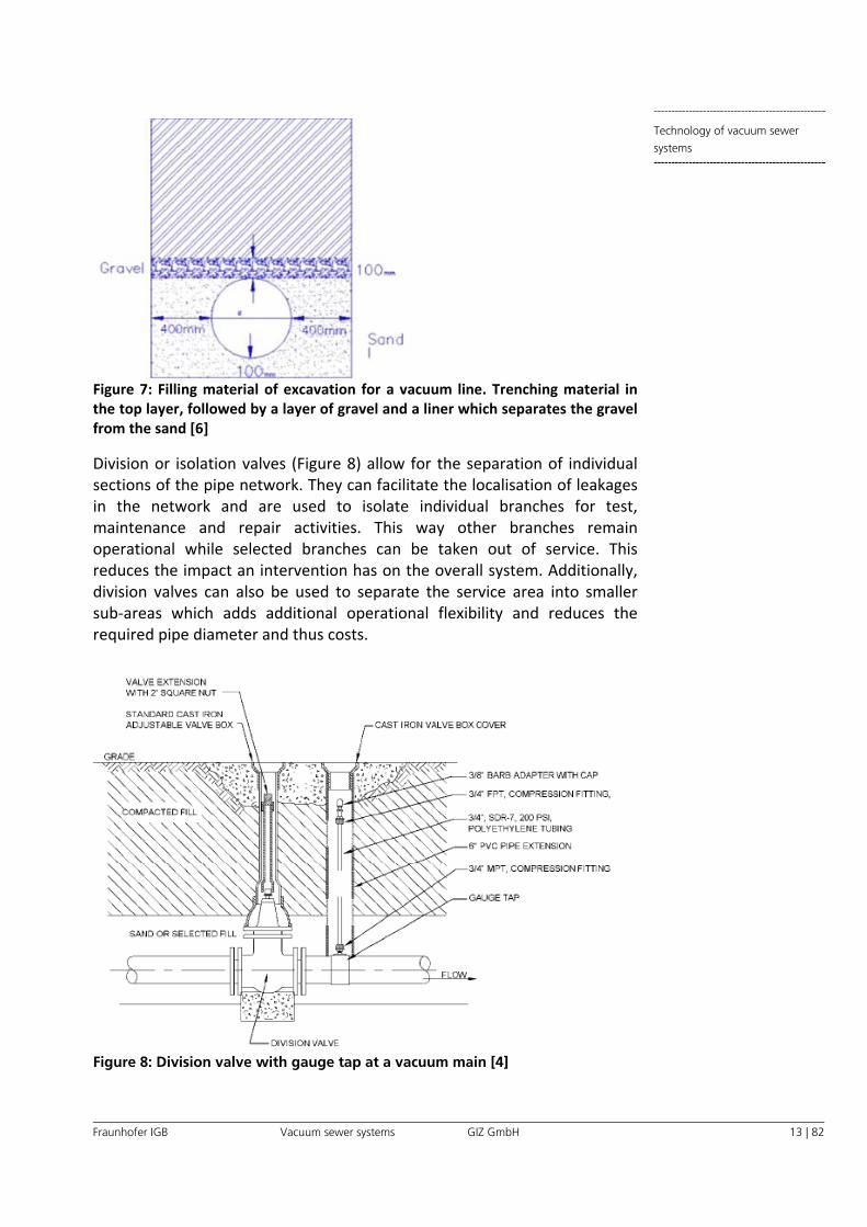
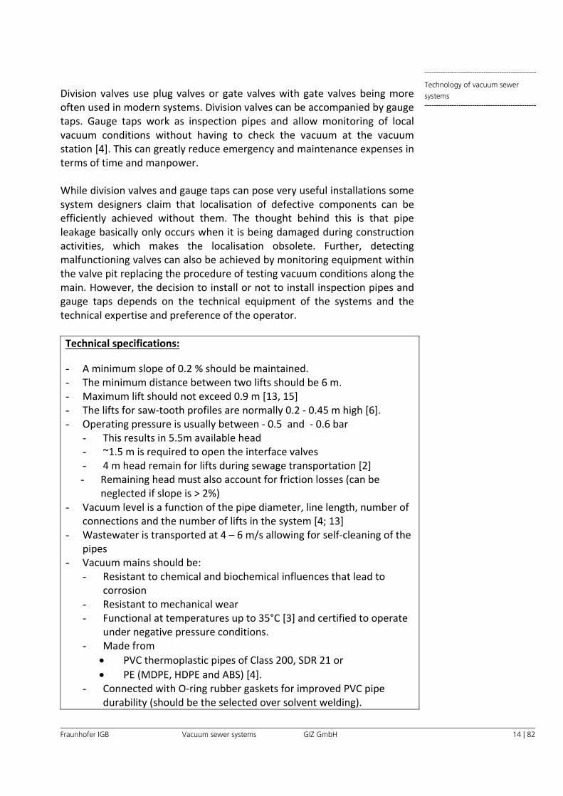
Figure 7: Filling material of excavation for a vacuum line. Trenching material in the top layer, followed by a layer of gravel and a liner which separates the gravel from the sand [6]
Division or isolation valves (Figure 8) allow for the separation of individual sections of the pipe network. They can facilitate the localisation of leakages in the network and are used to isolate individual branches for test, maintenance and repair activities. This way other branches remain operational while selected branches can be taken out of service. This reduces the impact an intervention has on the overall system. Additionally, division valves can also be used to separate the service area into smaller sub‐areas which adds additional operational flexibility and reduces the required pipe diameter and thus costs.
Figure 8: Division valve with gauge tap at a vacuum main [4]
Fraunhofer IGB Vacuum sewer systems GIZ GmbH 14 | 82
Technology of vacuum sewer
systems
Division valves use plug valves or gate valves with gate valves being more often used in modern systems. Division valves can be accompanied by gauge taps. Gauge taps work as inspection pipes and allow monitoring of local vacuum conditions without having to check the vacuum at the vacuum station [4]. This can greatly reduce emergency and maintenance expenses in terms of time and manpower. While division valves and gauge taps can pose very useful installations some system designers claim that localisation of defective components can be efficiently achieved without them. The thought behind this is that pipe leakage basically only occurs when it is being damaged during construction activities, which makes the localisation obsolete. Further, detecting malfunctioning valves can also be achieved by monitoring equipment within the valve pit replacing the procedure of testing vacuum conditions along the main. However, the decision to install or not to install inspection pipes and gauge taps depends on the technical equipment of the systems and the technical expertise and preference of the operator.
Technical specifications:
- A minimum slope of 0.2 % should be maintained. - The minimum distance between two lifts should be 6 m. - Maximum lift should not exceed 0.9 m [13, 15] - The lifts for saw‐tooth profiles are normally 0.2 ‐ 0.45 m high [6]. - Operating pressure is usually between ‐ 0.5 and ‐ 0.6 bar
- This results in 5.5m available head - ~1.5 m is required to open the interface valves - 4 m head remain for lifts during sewage transportation [2] - Remaining head must also account for friction losses (can be
neglected if slope is > 2%) - Vacuum level is a function of the pipe diameter, line length, number of
connections and the number of lifts in the system [4; 13] - Wastewater is transported at 4 – 6 m/s allowing for self‐cleaning of the
pipes - Vacuum mains should be:
- Resistant to chemical and biochemical influences that lead to corrosion
- Resistant to mechanical wear - Functional at temperatures up to 35°C [3] and certified to operate
under negative pressure conditions. - Made from
PVC thermoplastic pipes of Class 200, SDR 21 or
PE (MDPE, HDPE and ABS) [4]. - Connected with O‐ring rubber gaskets for improved PVC pipe
durability (should be the selected over solvent welding).
Fraunhofer IGB Vacuum sewer systems GIZ GmbH 15 | 82
Technology of vacuum sewer
systems
- When PE pipes are selected electronic welding is recommended for installing the fittings.
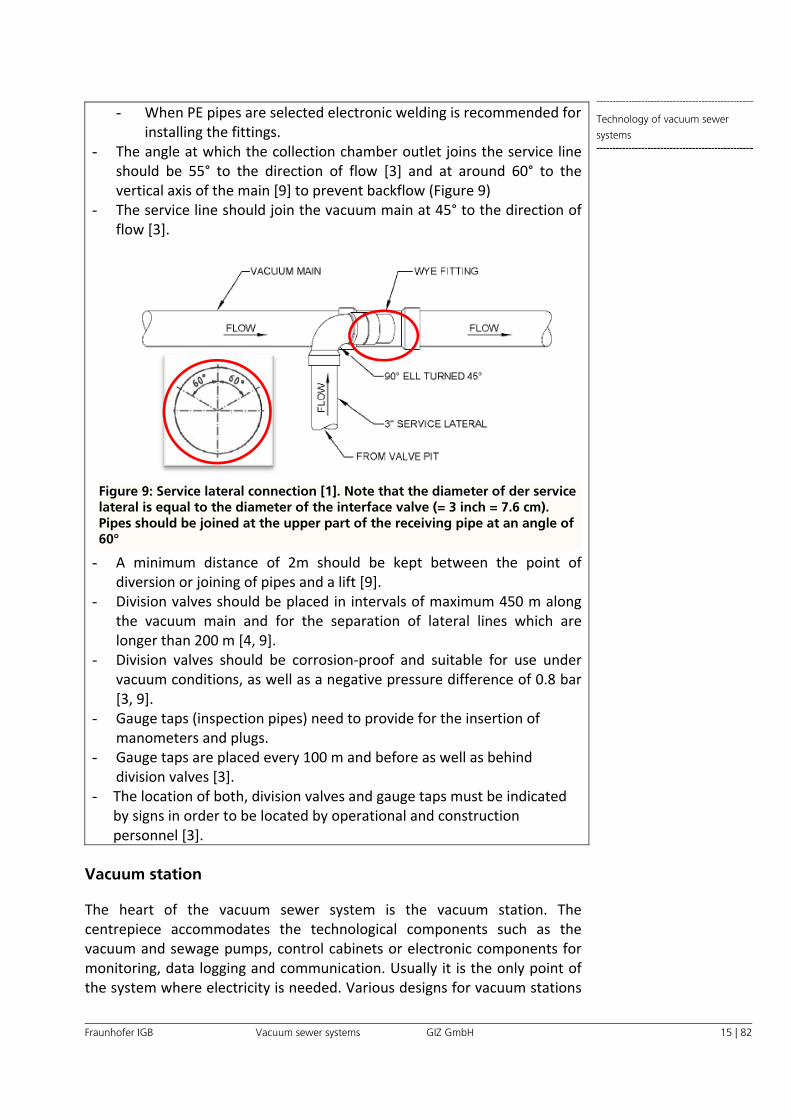
- The angle at which the collection chamber outlet joins the service line should be 55° to the direction of flow [3] and at around 60° to the vertical axis of the main [9] to prevent backflow (Figure 9)
- The service line should join the vacuum main at 45° to the direction of flow [3].
- A minimum distance of 2m should be kept between the point of diversion or joining of pipes and a lift [9].
- Division valves should be placed in intervals of maximum 450 m along the vacuum main and for the separation of lateral lines which are longer than 200 m [4, 9].
- Division valves should be corrosion‐proof and suitable for use under vacuum conditions, as well as a negative pressure difference of 0.8 bar [3, 9].
- Gauge taps (inspection pipes) need to provide for the insertion of manometers and plugs.
- Gauge taps are placed every 100 m and before as well as behind division valves [3].
- The location of both, division valves and gauge taps must be indicated by signs in order to be located by operational and construction personnel [3].
Vacuum station
The heart of the vacuum sewer system is the vacuum station. The centrepiece accommodates the technological components such as the vacuum and sewage pumps, control cabinets or electronic components for monitoring, data logging and communication. Usually it is the only point of the system where electricity is needed. Various designs for vacuum stations
Figure 9: Service lateral connection [1]. Note that the diameter of der service lateral is equal to the diameter of the interface valve (= 3 inch = 7.6 cm). Pipes should be joined at the upper part of the receiving pipe at an angle of 60°
Fraunhofer IGB Vacuum sewer systems GIZ GmbH 16 | 82
Technology of vacuum sewer
systems
have been developed. The flexibility in the design allows adapting the layout to different surroundings (see Figure 10). As noise and odour emissions from the station can affect the people living in proximity of the station and thus impact on the acceptance of the vacuum system the site selection should be carried out carefully. The distance to other buildings should be considered, as well as the placement at the lowest possible point of the service area since this will affect the static losses and thus the economics of the system.
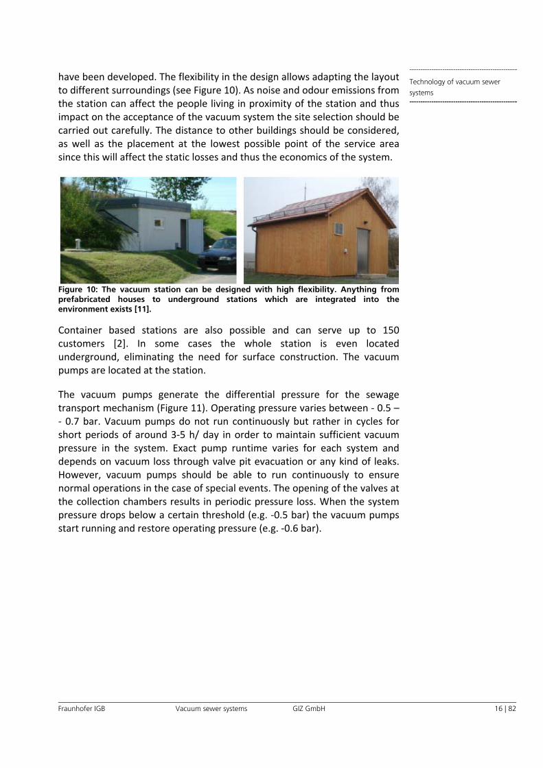
Figure 10: The vacuum station can be designed with high flexibility. Anything from prefabricated houses to underground stations which are integrated into the environment exists [11].
Container based stations are also possible and can serve up to 150 customers [2]. In some cases the whole station is even located underground, eliminating the need for surface construction. The vacuum pumps are located at the station.
The vacuum pumps generate the differential pressure for the sewage transport mechanism (Figure 11). Operating pressure varies between ‐ 0.5 – ‐ 0.7 bar. Vacuum pumps do not run continuously but rather in cycles for short periods of around 3‐5 h/ day in order to maintain sufficient vacuum pressure in the system. Exact pump runtime varies for each system and depends on vacuum loss through valve pit evacuation or any kind of leaks. However, vacuum pumps should be able to run continuously to ensure normal operations in the case of special events. The opening of the valves at the collection chambers results in periodic pressure loss. When the system pressure drops below a certain threshold (e.g. ‐0.5 bar) the vacuum pumps start running and restore operating pressure (e.g. ‐0.6 bar).
Fraunhofer IGB Vacuum sewer systems GIZ GmbH 17 | 82
Technology of vacuum sewer
systems
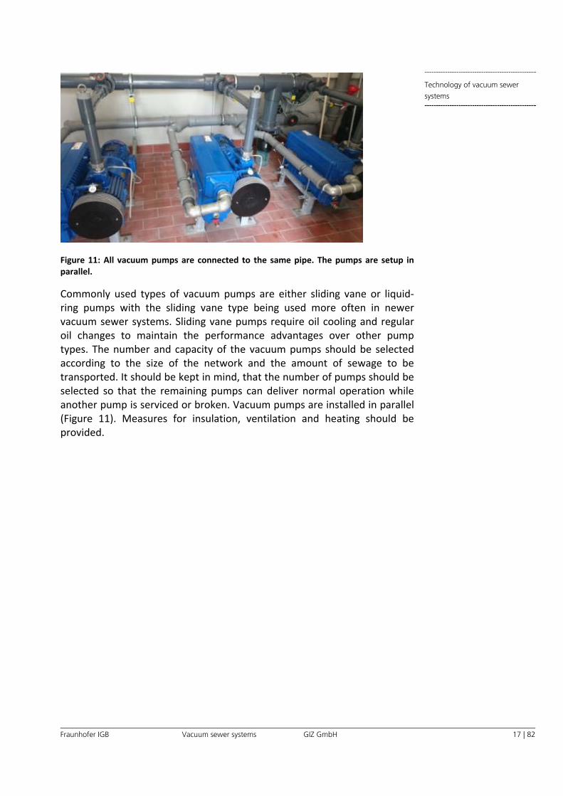
Figure 11: All vacuum pumps are connected to the same pipe. The pumps are setup in parallel.
Commonly used types of vacuum pumps are either sliding vane or liquid‐ring pumps with the sliding vane type being used more often in newer vacuum sewer systems. Sliding vane pumps require oil cooling and regular oil changes to maintain the performance advantages over other pump types. The number and capacity of the vacuum pumps should be selected according to the size of the network and the amount of sewage to be transported. It should be kept in mind, that the number of pumps should be selected so that the remaining pumps can deliver normal operation while another pump is serviced or broken. Vacuum pumps are installed in parallel (Figure 11). Measures for insulation, ventilation and heating should be provided.
Fraunhofer IGB Vacuum sewer systems GIZ GmbH 18 | 82
Technology of vacuum sewer
systems
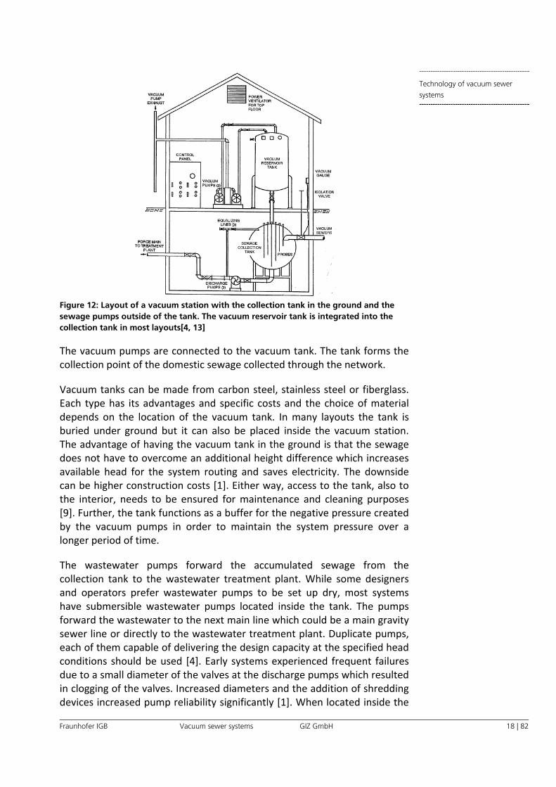
Figure 12: Layout of a vacuum station with the collection tank in the ground and the
sewage pumps outside of the tank. The vacuum reservoir tank is integrated into the
collection tank in most layouts[4, 13]
The vacuum pumps are connected to the vacuum tank. The tank forms the collection point of the domestic sewage collected through the network.
Vacuum tanks can be made from carbon steel, stainless steel or fiberglass. Each type has its advantages and specific costs and the choice of material depends on the location of the vacuum tank. In many layouts the tank is buried under ground but it can also be placed inside the vacuum station. The advantage of having the vacuum tank in the ground is that the sewage does not have to overcome an additional height difference which increases available head for the system routing and saves electricity. The downside can be higher construction costs [1]. Either way, access to the tank, also to the interior, needs to be ensured for maintenance and cleaning purposes [9]. Further, the tank functions as a buffer for the negative pressure created by the vacuum pumps in order to maintain the system pressure over a longer period of time.
The wastewater pumps forward the accumulated sewage from the collection tank to the wastewater treatment plant. While some designers and operators prefer wastewater pumps to be set up dry, most systems have submersible wastewater pumps located inside the tank. The pumps forward the wastewater to the next main line which could be a main gravity sewer line or directly to the wastewater treatment plant. Duplicate pumps, each of them capable of delivering the design capacity at the specified head conditions should be used [4]. Early systems experienced frequent failures due to a small diameter of the valves at the discharge pumps which resulted in clogging of the valves. Increased diameters and the addition of shredding devices increased pump reliability significantly [1]. When located inside the
Fraunhofer IGB Vacuum sewer systems GIZ GmbH 19 | 82
Technology of vacuum sewer
systems
vacuum tank, discharge pumps need to be certified to operate under vacuum pressure conditions [4].
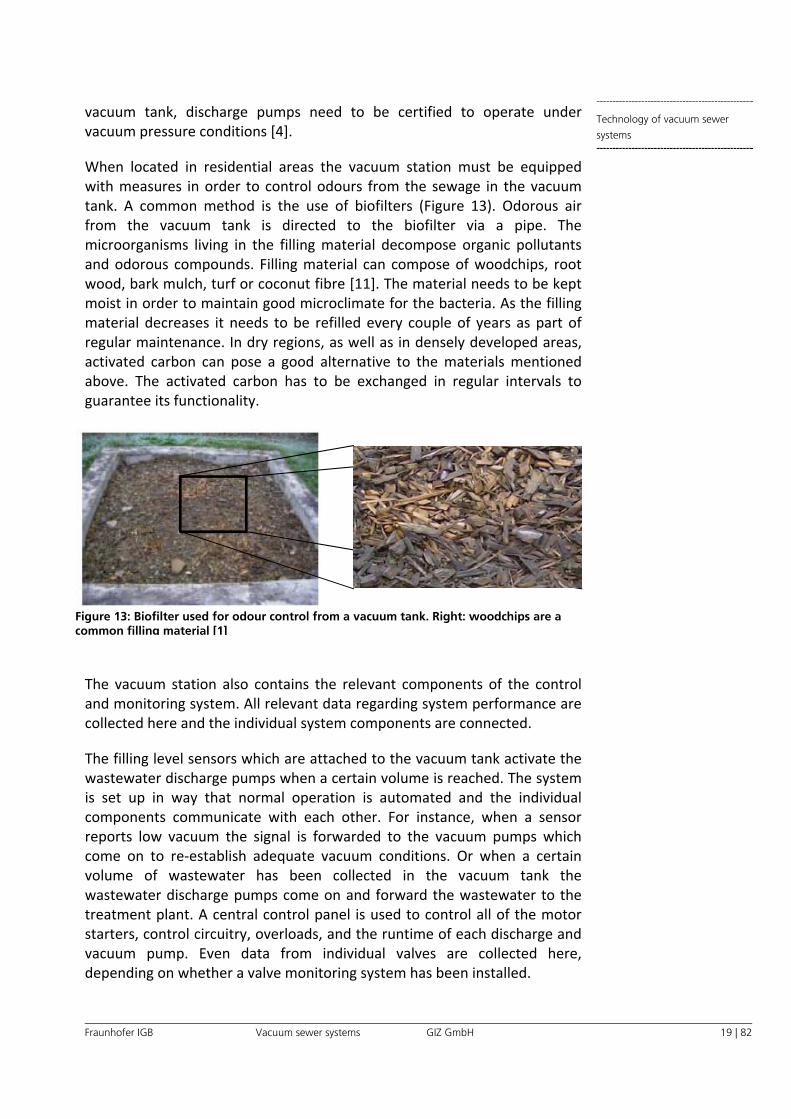
When located in residential areas the vacuum station must be equipped with measures in order to control odours from the sewage in the vacuum tank. A common method is the use of biofilters (Figure 13). Odorous air from the vacuum tank is directed to the biofilter via a pipe. The microorganisms living in the filling material decompose organic pollutants and odorous compounds. Filling material can compose of woodchips, root wood, bark mulch, turf or coconut fibre [11]. The material needs to be kept moist in order to maintain good microclimate for the bacteria. As the filling material decreases it needs to be refilled every couple of years as part of regular maintenance. In dry regions, as well as in densely developed areas, activated carbon can pose a good alternative to the materials mentioned above. The activated carbon has to be exchanged in regular intervals to guarantee its functionality.
The vacuum station also contains the relevant components of the control and monitoring system. All relevant data regarding system performance are collected here and the individual system components are connected.
The filling level sensors which are attached to the vacuum tank activate the wastewater discharge pumps when a certain volume is reached. The system is set up in way that normal operation is automated and the individual components communicate with each other. For instance, when a sensor reports low vacuum the signal is forwarded to the vacuum pumps which come on to re‐establish adequate vacuum conditions. Or when a certain volume of wastewater has been collected in the vacuum tank the wastewater discharge pumps come on and forward the wastewater to the treatment plant. A central control panel is used to control all of the motor starters, control circuitry, overloads, and the runtime of each discharge and vacuum pump. Even data from individual valves are collected here, depending on whether a valve monitoring system has been installed.
Figure 13: Biofilter used for odour control from a vacuum tank. Right: woodchips are a common filling material [1]
Fraunhofer IGB Vacuum sewer systems GIZ GmbH 20 | 82
Technology of vacuum sewer
systems
Additionally, the control and monitoring system is equipped with an alarm system which notifies the operator via a text message in the event of a fault. An adequate transmitting device (e.g. modem) equipped with backup power supply needs to be provided.
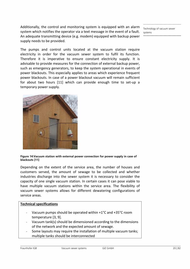
The pumps and control units located at the vacuum station require electricity in order for the vacuum sewer system to fulfil its function. Therefore it is imperative to ensure constant electricity supply. It is advisable to provide measures for the connection of external backup power, such as emergency generators, to keep the system operational in events of power blackouts. This especially applies to areas which experience frequent power blackouts. In case of a power blackout vacuum will remain sufficient for about two hours [11] which can provide enough time to set‐up a temporary power supply.
Figure 14:Vacuum station with external power connection for power supply in case of blackouts [11]
Depending on the extent of the service area, the number of houses and customers served, the amount of sewage to be collected and whether industries discharge into the sewer system it is necessary to consider the capacity of one single vacuum station. In certain cases it can pose viable to have multiple vacuum stations within the service area. The flexibility of vacuum sewer systems allows for different dewatering configurations of service areas.
Technical specifications
‐ Vacuum pumps should be operated within +1°C and +35°C room temperature [3, 9].
‐ Vacuum tank(s) should be dimensioned according to the dimensions of the network and the expected amount of sewage.
‐ Some layouts may require the installation of multiple vacuum tanks; multiple tanks should be interconnected
Fraunhofer IGB Vacuum sewer systems GIZ GmbH 21 | 82
Technology of vacuum sewer
systems
‐ Additionally, the filling control must react to the following filling levels [9]:
o Emergency shut off filling level: Interrupts the vacuum build up but continues the discharge process by wastewater pumps
o Start filling level: Initiates discharge of wastewater by wastewater pumps
o Stop filling level: Interrupts the discharge process of the wastewater pumps
‐ To ensure adequate service the following alarms need to be in place [9]:
o Alarm for insufficient vacuum: Is triggered when system vacuum falls below a previously determined threshold (usually ‐0.3 bar)
o Alarm for wastewater level too high: Is triggered when the maximum filling level threshold inside the vacuum tank is exceeded. Not more than half of the vacuum tank’s volume must be filled with wastewater.
o Alarm for faults: Is triggered when an important system component is malfunctioning, a power blackout occurs or the maximum continuous runtime of the vacuum pump is exceeded.
2.3. Manufacturers / System providers
Since vacuum sewers are still not very common the number of technology providers available is limited. However, the following list presents a selection of companies offering vacuum sewer solutions on the market. The list provides an overview and does not claim to be complete (in alphabetical order):
AIRVAC / ROEDIGER – Aqseptence Group
ROEDIGER and AIRVAC have been acquired by Aqseptence Group from Bilfinger Water Technologies in 2016. The two companies are associated and provide the same technology.
Fraunhofer IGB Vacuum sewer systems GIZ GmbH 22 | 82
Technology of vacuum sewer
systems
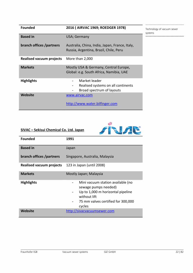
Founded 2016 ( AIRVAC 1969; ROEDGER 1978)
Based in
branch offices /partners
USA; Germany
Australia, China, India, Japan, France, Italy, Russia, Argentina, Brazil, Chile, Peru
Realised vacuum projects More than 2,000
Markets Mostly USA & Germany, Central Europe, Global: e.g. South Africa, Namibia, UAE
Highlights - Market leader - Realised systems on all continents - Broad spectrum of layouts
Website www.airvac.com
http://www.water.bilfinger.com
SIVAC – Sekisui Chemical Co. Ltd. Japan
Founded 1991
Based in
branch offices /partners
Japan
Singapore, Australia, Malaysia
Realised vacuum projects 123 in Japan (until 2008)
Markets Mostly Japan; Malaysia
Highlights - Mini vacuum station available (no sewage pumps needed)
- Up to 1,000 m horizontal pipeline without lift
- 75 mm valves certified for 300,000 cycles
Website http://sivacvacuumsewer.com
Fraunhofer IGB Vacuum sewer systems GIZ GmbH 23 | 82
Technology of vacuum sewer
systems
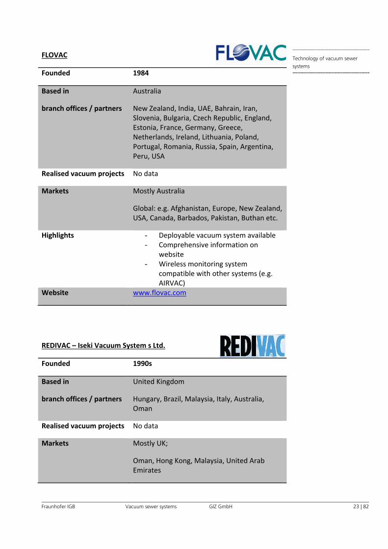
FLOVAC
Founded 1984
Based in
branch offices / partners
Australia
New Zealand, India, UAE, Bahrain, Iran, Slovenia, Bulgaria, Czech Republic, England, Estonia, France, Germany, Greece, Netherlands, Ireland, Lithuania, Poland, Portugal, Romania, Russia, Spain, Argentina, Peru, USA
Realised vacuum projects No data
Markets Mostly Australia
Global: e.g. Afghanistan, Europe, New Zealand, USA, Canada, Barbados, Pakistan, Buthan etc.
Highlights - Deployable vacuum system available - Comprehensive information on
website - Wireless monitoring system
compatible with other systems (e.g. AIRVAC)
Website www.flovac.com
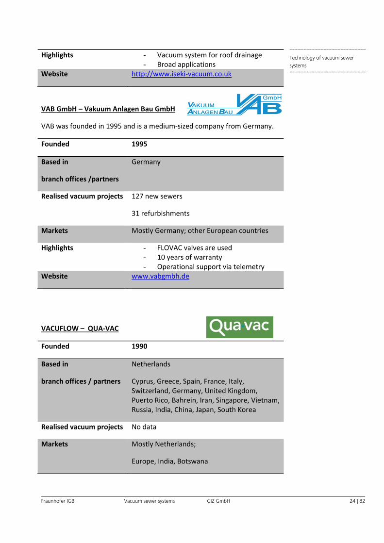
REDIVAC – Iseki Vacuum System s Ltd.
Founded 1990s
Based in
branch offices / partners
United Kingdom
Hungary, Brazil, Malaysia, Italy, Australia, Oman
Realised vacuum projects No data
Markets Mostly UK;
Oman, Hong Kong, Malaysia, United Arab Emirates
Fraunhofer IGB Vacuum sewer systems GIZ GmbH 24 | 82
Technology of vacuum sewer
systems
Highlights - Vacuum system for roof drainage - Broad applications
Website http://www.iseki‐vacuum.co.uk
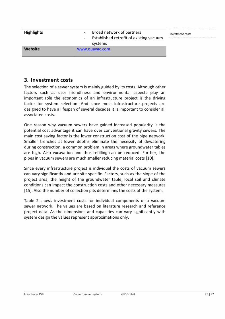
VAB GmbH – Vakuum Anlagen Bau GmbH
VAB was founded in 1995 and is a medium‐sized company from Germany.
Founded 1995
Based in
branch offices /partners
Germany
Realised vacuum projects 127 new sewers
31 refurbishments
Markets Mostly Germany; other European countries
Highlights - FLOVAC valves are used - 10 years of warranty - Operational support via telemetry
Website www.vabgmbh.de
VACUFLOW – QUA‐VAC
Founded 1990
Based in
branch offices / partners
Netherlands
Cyprus, Greece, Spain, France, Italy, Switzerland, Germany, United Kingdom, Puerto Rico, Bahrein, Iran, Singapore, Vietnam, Russia, India, China, Japan, South Korea
Realised vacuum projects No data
Markets Mostly Netherlands;
Europe, India, Botswana
Fraunhofer IGB Vacuum sewer systems GIZ GmbH 25 | 82
Investment costs Highlights - Broad network of partners - Established retrofit of existing vacuum
systems Website www.quavac.com
3. Investment costs The selection of a sewer system is mainly guided by its costs. Although other factors such as user friendliness and environmental aspects play an important role the economics of an infrastructure project is the driving factor for system selection. And since most infrastructure projects are designed to have a lifespan of several decades it is important to consider all associated costs.
One reason why vacuum sewers have gained increased popularity is the potential cost advantage it can have over conventional gravity sewers. The main cost saving factor is the lower construction cost of the pipe network. Smaller trenches at lower depths eliminate the necessity of dewatering during construction, a common problem in areas where groundwater tables are high. Also excavation and thus refilling can be reduced. Further, the pipes in vacuum sewers are much smaller reducing material costs [10].
Since every infrastructure project is individual the costs of vacuum sewers can vary significantly and are site specific. Factors, such as the slope of the project area, the height of the groundwater table, local soil and climate conditions can impact the construction costs and other necessary measures [15]. Also the number of collection pits determines the costs of the system.
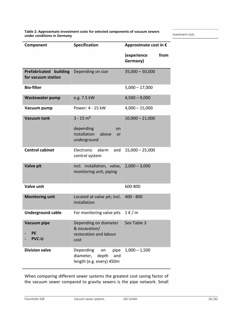
Table 2 shows investment costs for individual components of a vacuum sewer network. The values are based on literature research and reference project data. As the dimensions and capacities can vary significantly with system design the values represent approximations only.
Fraunhofer IGB Vacuum sewer systems GIZ GmbH 26 | 82
Investment costs Table 2: Approximate investment costs for selected components of vacuum sewers under conditions in Germany
Component Specification Approximate cost in €
(experience from Germany)
Prefabricated building for vacuum station
Depending on size 35,000 – 50,000
Bio‐filter 5,000 – 17,000
Wastewater pump e.g. 7.5 kW 4,500 – 9,000
Vacuum pump Power: 4 ‐ 15 kW 4,000 – 15,000
Vacuum tank 3 ‐ 15 m³
depending on installation above or underground
10,000 – 21,000
Control cabinet Electronic alarm and control system
15,000 – 25,000
Valve pit incl. installation, valve, monitoring unit, piping
2,000 – 3,000
Valve unit 600‐800
Monitoring unit Located at valve pit; incl. installation
400 ‐ 800
Underground cable For monitoring valve pits 1 € / m
Vacuum pipe
- PE - PVC‐U
Depending on diameter & excavation/ restoration and labour cost
See Table 3
Division valve Depending on pipe diameter, depth and length (e.g. every) 450m
1,000 – 1,500
When comparing different sewer systems the greatest cost saving factor of the vacuum sewer compared to gravity sewers is the pipe network. Small
Fraunhofer IGB Vacuum sewer systems GIZ GmbH 27 | 82
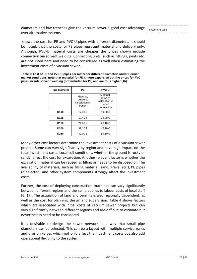
Investment costs diameters and low trenches give the vacuum sewer a good cost advantage over alternative systems.
shows the cost for PE and PVC‐U pipes with different diameters. It should be noted, that the costs for PE pipes represent material and delivery only. Although, PVC‐U material costs are cheaper the prices shown include connection via solvent welding. Connecting units, such as fittings, joints etc. are not listed here and need to be considered as well when estimating the investment costs of a vacuum sewer.
Table 3: Cost of PE and PVC-U pipes per meter for different diameters under German market conditions; note that material for PE is more expensive but the prices for PVC pipes include solvent welding (not included for PE) and are thus higher [16]
Pipe diameter PE PVC-U
Material, delivery,
installation in trench
Material, delivery,
installation in trench
connection
D110 17,30 € 19,20 €
D125 19,40 € 22,30 €
D160 24,60 € 28,10 €
D200 31,10 € 42,10 €
D250 40,00 € 59,50 €
Many other cost factors determine the investment costs of a vacuum sewer project. Some can vary significantly by region and have high impact on the total investment costs. Local soil conditions, whether the ground is rocky or sandy, affect the cost for excavation. Another relevant factor is whether the excavation material can be reused as filling or needs to be disposed of. The availability of materials, such as filling material (sand, gravel etc.), PE pipes (if selected) and other system components strongly affect the investment costs.
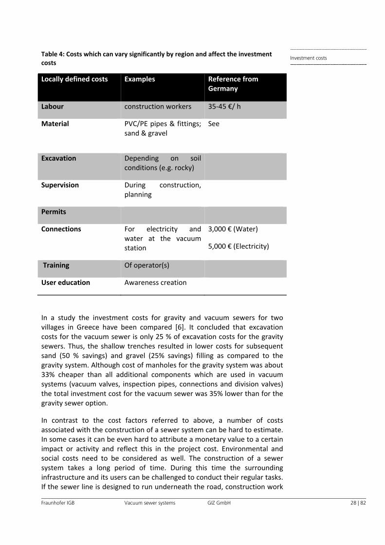
Further, the cost of deploying construction machines can vary significantly between different regions and the same applies to labour costs of local staff [6, 17]. The acquisition of land and permits is also regionally dependent, as well as the cost for planning, design and supervision. Table 4 shows factors which are associated with initial costs of vacuum sewer projects but can vary significantly between different regions and are difficult to estimate but nevertheless need to be considered.
It is desirable to design the sewer network in a way that small pipe diameters can be selected. This can be a layout with multiple service zones and division valves which not only affect the investment costs but also add operational flexibility to the system.
Fraunhofer IGB Vacuum sewer systems GIZ GmbH 28 | 82
Investment costs Table 4: Costs which can vary significantly by region and affect the investment costs
Locally defined costs Examples Reference from Germany
Labour construction workers 35‐45 €/ h
Material PVC/PE pipes & fittings; sand & gravel
See
Excavation Depending on soil conditions (e.g. rocky)
Supervision During construction, planning
Permits
Connections For electricity and water at the vacuum station
3,000 € (Water)
5,000 € (Electricity)
Training Of operator(s)
User education Awareness creation
In a study the investment costs for gravity and vacuum sewers for two villages in Greece have been compared [6]. It concluded that excavation costs for the vacuum sewer is only 25 % of excavation costs for the gravity sewers. Thus, the shallow trenches resulted in lower costs for subsequent sand (50 % savings) and gravel (25% savings) filling as compared to the gravity system. Although cost of manholes for the gravity system was about 33% cheaper than all additional components which are used in vacuum systems (vacuum valves, inspection pipes, connections and division valves) the total investment cost for the vacuum sewer was 35% lower than for the gravity sewer option.
In contrast to the cost factors referred to above, a number of costs associated with the construction of a sewer system can be hard to estimate. In some cases it can be even hard to attribute a monetary value to a certain impact or activity and reflect this in the project cost. Environmental and social costs need to be considered as well. The construction of a sewer system takes a long period of time. During this time the surrounding infrastructure and its users can be challenged to conduct their regular tasks. If the sewer line is designed to run underneath the road, construction work
Fraunhofer IGB Vacuum sewer systems GIZ GmbH 29 | 82
Operation and Maintenance costswill affect traffic and subsequently people and goods travelling on the road. Also, the accessibility of shops or other commercial buildings can be affected from sewer construction imposing a financial burden on the affected owners. Also, the environmental footprint of constructing and operating a sewer can be significant, especially when dewatering of trenches is required, let alone the environmental impact of wastewater leaking from conventional sewers into the ground and groundwater. Although these aspects are hard to quantify it can be assumed that the flexibility of design (e.g. construction of lines on the sidewalk), shallower trenches and smaller pipe diameters make the construction of a vacuum sewer less invasive than the installation of a gravity sewer. Further, the mentioned characteristics result in shorter construction times of vacuum sewers. These ‘associated costs’ should be evaluated in addition to the investment costs when deciding on the system for a sewer project.
4. Operation and Maintenance costs
Whether an infrastructure investment is sustainable depends on how much attention the system requires and how the costs for operation and maintenance of the system are designed. In any case a comparative cost analysis should be undertaken over a long period of time (e.g. 60 year life cycle cost). The analysis will give weight to the running costs of the analysed systems which will then reveal the more economical option.
When comparing the Operation and Maintenance (O&M) costs of vacuum sewers with O&M costs of conventional gravity sewers different authors come to different conclusions. While Masteller & Moler [18] state that O&M costs in vacuum sewers are higher due to the high number of mechanical elements, higher electricity costs and the need for personnel to monitor the system, Beauclair [19] and Islam [6] come to the conclusion that O&M costs are lower or similar to gravity systems due to the high scouring velocities and similar electricity costs. In conventional gravity systems it can be necessary to use pumping stations when the pipes have to be installed too deep beneath the surface to guarantee the necessary slope. Further, in conventional gravity systems the transport relies on sufficient water to convey the waste contained in sewage. Sometimes flow can be insufficient and the objects or accumulated substances cause blockages in the pipe. These need to be removed by additional flushing, for example with a hydroblaster. Due to the high scouring velocities this is not required in vacuum sewer systems.
O&M costs can vary significantly depending on how well the system is designed and how reconditioning of system failures is managed. Electricity and personnel costs are the major cost components. Both are determined by the skills of the operating personnel and can vary significantly between
Fraunhofer IGB Vacuum sewer systems GIZ GmbH 30 | 82
Operation and Maintenance costsdifferent countries and over time. Material costs are also important but usually are much lower than the electricity and personnel costs. However, if a vacuum sewer network is not designed and maintained properly and frequent failures occur (e.g. malfunctioning valves) the material costs can increase drastically.
4.1. Electricity costs
In most vacuum sewer designs the only point of electricity consumption is at the vacuum station. Some systems have monitoring devices installed at the valve pits which, depending on the power source, can require additional electricity inputs. At the vacuum station most of the electricity is used to run the vacuum and sewerage pumps. Apart from the pumps, electricity is needed for the control and monitoring system, the alarm system as well as for the recording and transmission of operational data. Further, electricity might be required for ventilation, heating and cooling of the vacuum station [15].
The electricity consumption of a vacuum sewer is mainly governed by the runtime of the vacuum pumps. Electricity for the vacuum pumps can make up to 80% of the total electricity consumption [11]. Since the vacuum pumps are responsible for maintaining and restoring adequate vacuum conditions the electricity consumption is a function of the loss of vacuum from leaks (e.g. faulty valves) and the opening frequency of the valves. The frequency of the occurrence of these leaks as well as the reconditioning time for restoring normal operation affects the runtime of the vacuum pumps. During normal operation the runtime of the vacuum pumps is predetermined by the system layout. Every valve opening represents a small loss of vacuum. Thus, the higher the frequency of valve opening the more vacuum is lost and needs to be restored by the pumps. The opening frequency is a function of multiple design parameters. Especially, the air‐to‐liquid ratio at the valve pits has implications for the electrical energy demand. The higher the ratio, the higher is the electricity consumption. Further, the number of house connections and the number of people discharging into a valve pit determine how often the pit needs to be evacuated and thus how often the interface opens. Finally, user behaviour, such as long showers, and appliances, such as full flush toilets, contribute to increased wastewater generation which also affects the frequency of the pit evacuation and thus vacuum pump runtime. In addition, the increased amount of wastewater extends the runtime of the sewage pumps at the vacuum station.
The cost of electricity is a variable cost factor. The price of electricity can vary significantly between regions and can even depend on the time of day
Fraunhofer IGB Vacuum sewer systems GIZ GmbH 31 | 82
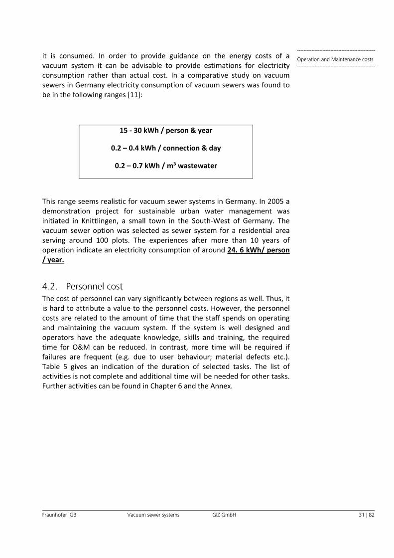
Operation and Maintenance costsit is consumed. In order to provide guidance on the energy costs of a vacuum system it can be advisable to provide estimations for electricity consumption rather than actual cost. In a comparative study on vacuum sewers in Germany electricity consumption of vacuum sewers was found to be in the following ranges [11]:
15 ‐ 30 kWh / person & year
0.2 – 0.4 kWh / connection & day
0.2 – 0.7 kWh / m³ wastewater
This range seems realistic for vacuum sewer systems in Germany. In 2005 a demonstration project for sustainable urban water management was initiated in Knittlingen, a small town in the South‐West of Germany. The vacuum sewer option was selected as sewer system for a residential area serving around 100 plots. The experiences after more than 10 years of operation indicate an electricity consumption of around 24. 6 kWh/ person / year.
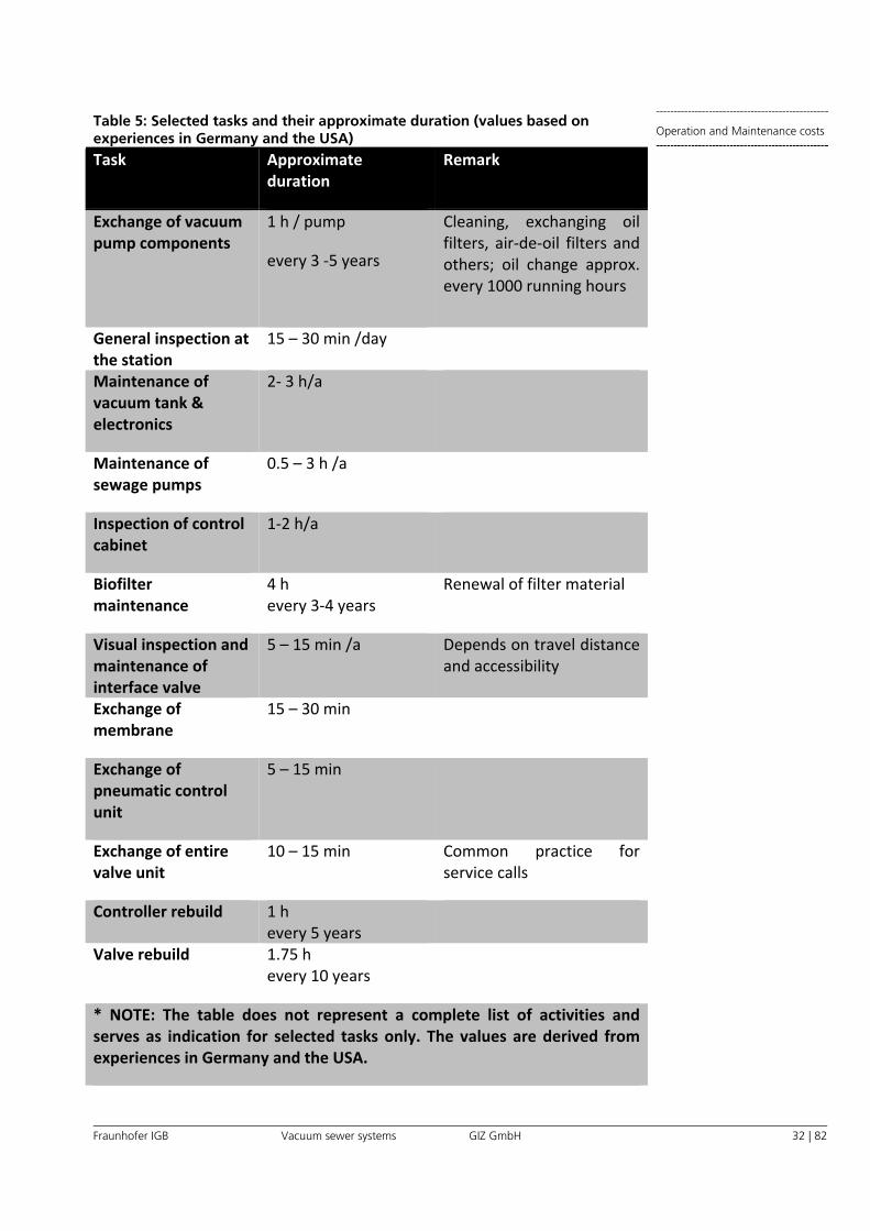
4.2. Personnel cost The cost of personnel can vary significantly between regions as well. Thus, it is hard to attribute a value to the personnel costs. However, the personnel costs are related to the amount of time that the staff spends on operating and maintaining the vacuum system. If the system is well designed and operators have the adequate knowledge, skills and training, the required time for O&M can be reduced. In contrast, more time will be required if failures are frequent (e.g. due to user behaviour; material defects etc.). Table 5 gives an indication of the duration of selected tasks. The list of activities is not complete and additional time will be needed for other tasks. Further activities can be found in Chapter 6 and the Annex.
Fraunhofer IGB Vacuum sewer systems GIZ GmbH 32 | 82
Operation and Maintenance costsTable 5: Selected tasks and their approximate duration (values based on experiences in Germany and the USA)
Task Approximate duration
Remark
Exchange of vacuum pump components
1 h / pump
every 3 ‐5 years
Cleaning, exchanging oil filters, air‐de‐oil filters and others; oil change approx. every 1000 running hours
General inspection at the station
15 – 30 min /day
Maintenance of vacuum tank & electronics
2‐ 3 h/a
Maintenance of sewage pumps
0.5 – 3 h /a
Inspection of control cabinet
1‐2 h/a
Biofilter maintenance
4 h every 3‐4 years
Renewal of filter material
Visual inspection and maintenance of interface valve
5 – 15 min /a Depends on travel distance and accessibility
Exchange of membrane
15 – 30 min
Exchange of pneumatic control unit
5 – 15 min
Exchange of entire valve unit
10 – 15 min Common practice for service calls
Controller rebuild 1 h every 5 years
Valve rebuild 1.75 h every 10 years
* NOTE: The table does not represent a complete list of activities and serves as indication for selected tasks only. The values are derived from experiences in Germany and the USA.
Fraunhofer IGB Vacuum sewer systems GIZ GmbH 33 | 82
Operation and Maintenance costsIt should be kept in mind that a valve monitoring system facilitates the work of the operator and faults can be localised quickly, thus reducing time and personnel cost.
A comprehensive operator survey conducted for 49 systems in the United States (20% of all operating systems in 2003) revealed the amount of labour associated with vacuum sewer systems. Most operators viewed the work associated with the vacuum station similar to the work required for a pumping station in a gravity system. The average values are a realistic representation of a normally operating system. The figures highlight the small amount of time associated with the mains which is a major advantage over gravity systems and benefits the operators. For the vacuum valves some operators reported preventive maintenance as routine. However, it should be noted, that the majority of labour related to vacuum valves is associated with service calls, but still remains low.
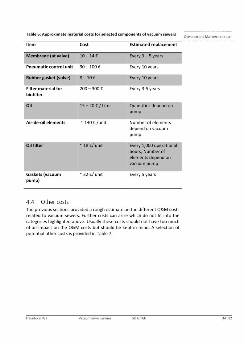
4.3. Material cost The cost of material highly depends on the frequency and severity of faults in the system. A well designed and maintained system with few faults will require materials less frequent than systems where maintenance is poor and system failures are common. Since the majority of faults and damages occur at the valve pit the materials required for the controller and the interface valve are the most relevant material costs. Table 6 shows the material costs for selected components of vacuum sewers.
Fraunhofer IGB Vacuum sewer systems GIZ GmbH 34 | 82
Operation and Maintenance costsTable 6: Approximate material costs for selected components of vacuum sewers
Item Cost Estimated replacement
Membrane (at valve) 10 – 14 € Every 3 – 5 years
Pneumatic control unit 90 – 100 € Every 10 years
Rubber gasket (valve) 8 – 10 € Every 10 years
Filter material for biofilter
200 – 300 € Every 3‐5 years
Oil 15 – 20 € / Liter Quantities depend on pump
Air‐de‐oil elements ~ 140 € /unit Number of elements depend on vacuum pump
Oil filter ~ 18 €/ unit
Every 1,000 operational hours; Number of elements depend on vacuum pump
Gaskets (vacuum pump)
~ 32 €/ unit Every 5 years
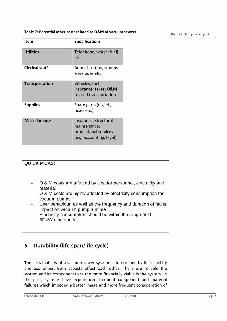
4.4. Other costs The previous sections provided a rough estimate on the different O&M costs related to vacuum sewers. Further costs can arise which do not fit into the categories highlighted above. Usually these costs should not have too much of an impact on the O&M costs but should be kept in mind. A selection of potential other costs is provided in Table 7.
Fraunhofer IGB Vacuum sewer systems GIZ GmbH 35 | 82
Durability (life span/life cycle) Table 7: Potential other costs related to O&M of vacuum sewers
Item Specifications
Utilities Telephone, water (fuel) etc.
Clerical staff Administration, stamps, envelopes etc.
Transportation Vehicles; fuel; insurance; taxes; O&M related transportation
Supplies Spare parts (e.g. oil, fuses etc.)
Miscellaneous Insurance; structural maintenance; professional services (e.g. accounting, legal)
QUICK PICKS:
- O & M costs are affected by cost for personnel, electricity and material
- O & M costs are highly affected by electricity consumption for vacuum pumps
- User behaviour, as well as the frequency and duration of faults impact on vacuum pump runtime
- Electricity consumption should be within the range of 10 – 30 kWh /person /a
5. Durability (life span/life cycle)
The sustainability of a vacuum sewer system is determined by its reliability and economics. Both aspects affect each other. The more reliable the system and its components are the more financially viable is the system. In the past, systems have experienced frequent component and material failures which impeded a better image and more frequent consideration of
Fraunhofer IGB Vacuum sewer systems GIZ GmbH 36 | 82
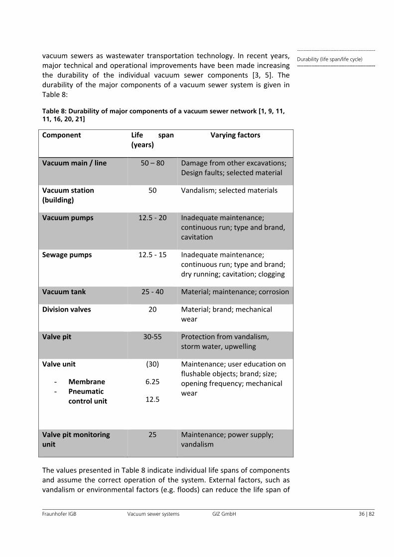
Durability (life span/life cycle) vacuum sewers as wastewater transportation technology. In recent years, major technical and operational improvements have been made increasing the durability of the individual vacuum sewer components [3, 5]. The durability of the major components of a vacuum sewer system is given in Table 8:
Table 8: Durability of major components of a vacuum sewer network [1, 9, 11, 11, 16, 20, 21]
Component Life span (years)
Varying factors
Vacuum main / line 50 – 80 Damage from other excavations; Design faults; selected material
Vacuum station (building)
50 Vandalism; selected materials
Vacuum pumps 12.5 ‐ 20 Inadequate maintenance; continuous run; type and brand, cavitation
Sewage pumps 12.5 ‐ 15 Inadequate maintenance; continuous run; type and brand; dry running; cavitation; clogging
Vacuum tank 25 ‐ 40 Material; maintenance; corrosion
Division valves 20 Material; brand; mechanical wear
Valve pit 30‐55 Protection from vandalism, storm water, upwelling
Valve unit
- Membrane - Pneumatic
control unit
(30)
6.25
12.5
Maintenance; user education on flushable objects; brand; size; opening frequency; mechanical wear
Valve pit monitoring unit
25 Maintenance; power supply; vandalism
The values presented in Table 8 indicate individual life spans of components and assume the correct operation of the system. External factors, such as vandalism or environmental factors (e.g. floods) can reduce the life span of
Fraunhofer IGB Vacuum sewer systems GIZ GmbH 37 | 82
Durability (life span/life cycle) the components. Besides the life span in years, Table 8 also shows which factors influence the durability of the components. It has to be kept in mind that some components of the vacuum sewer are mechanical (e.g. pumps, valves etc.) and that, like mechanical components in other systems, they are subject to mechanical wear.
Although every part will fail or break at some point, a lot can be done to extend the life cycle of each component. Preventive action approaches minimise the risk of failures before they emerge. For vacuum sewers preventive action starts in the design phase. Appropriate design can increase life cycle time of vacuum sewer components. Proper coordination of components and their individual properties is crucial. It is imperative to determine the amount of wastewater and select the components according to the required capacities. This applies not only to vacuum and sewerage pump capacities but also to the diameter of the vacuum mains. Due to lower transport velocities vacuum mains which have a large pipe diameter are more prone to scaling and precipitation from compounds contained in the wastewater. This can affect the durability of the selected material and thus the life span. Additionally, specific measures might be required to adjust the vacuum sewer to the environmental settings. If the area for which the vacuum sewer is designed experiences heavy rainfalls which can lead to floods, this needs to be taken into account in the design. Measures which prevent upwelling of pits and mains or which minimise the amount of storm water entering the valve pits need to be considered. Further, the components need to be protected from vandalism or theft.
In the design stage a comprehensive plan should be developed on how to resolve system failures as fast as possible. Especially when there is no valve monitoring system in place it can take time to localize the point of failure in the systems. The longer it takes to localize and repair a vacuum leak or a faulty valve the longer the vacuum pumps have to run in order to restore or maintain vacuum conditions. This can increase mechanical wear of the pumps and reduce their life span. Similarly, a comprehensive maintenance plan based on the recommendations of the manufacturers of the individual system components is required. Regular inspection, oiling, replacement, cleaning etc. will increase durability of the integral parts of the system and minimise the need for emergency actions. Additionally, the technical knowledge and capacity of the operational personnel needs to be adequate to identify problems, take appropriate action as well as carry out preventive measures. Capacity building should be considered in areas where operational and maintenance knowledge is suspected to be insufficient.
In any case, the introduction of a vacuum sewer system needs to be accompanied by a comprehensive user education. The people discharging into vacuum sewers need to be aware of the sensitivity of the interface valve towards large objects which can affect the functionality or even break the valve. Awareness creation on flushable objects is especially important in
Fraunhofer IGB Vacuum sewer systems GIZ GmbH 38 | 82
Operational and maintenance
skills required
areas where adequate solid waste management is missing in order to increase durability of system components.
The availability of components needs to be checked and ensured when choosing a vacuum sewer system. In the event of system failure or material wear individual parts need to be available to ensure quick recovery of the sewer function. Therefore, sufficient stock and long‐term material supply need to be assured. It is advisable to discuss the supply of materials with the selected manufacturer in order to have an estimate in mind where the closest supplier is located and how long it takes to deliver the requested materials. Local providers of individual parts can pose a valuable alternative. However, quality assurance standards must be met and the use of materials other than supplied by the system manufacturer can lead to incompatibility with other components. Strong collaboration with the manufacturer is crucial. The company can use its own network to facilitate the contact with appropriate suppliers in the region.
6. Operational and maintenance skills required
Cost is not the only consideration that needs to be taken into account when selecting a sewer system. The availability of knowledge and skills should also influence the decision for an alternative. Vacuum systems have the reputation of being O&M intensive. While this has been true for earlier systems newer projects have benefitted from many technical and operational improvements which have reduced O&M requirements [22].
Operating and maintaining a vacuum sewer does indeed require technical expertise and demand a lot from the operator in terms of knowledge and skills. While effective operation of a vacuum sewer system begins with proper design and construction O&M requires at least one trained operator that is familiar with the system, including the locations of all the collection chambers, lines, division valves and other key components. The operator must understand how the main components of the vacuum sewer system are interrelated and work together as a system. Ideally, the training of operator(s) should commence while the system is still under construction in order to become familiar with the system and its components [22]. Maintenance of the vacuum sewer system can be divided into two groups: normal including preventative maintenance, and emergency maintenance.
6.1. Normal and preventive maintenance Concentrating on the normal and preventative maintenance minimizes the need of emergency maintenance [15]. As vacuum systems must operate and be maintained all year long variations in workload can occur. Thus, it is important to plan and schedule preventive maintenance. A maintenance
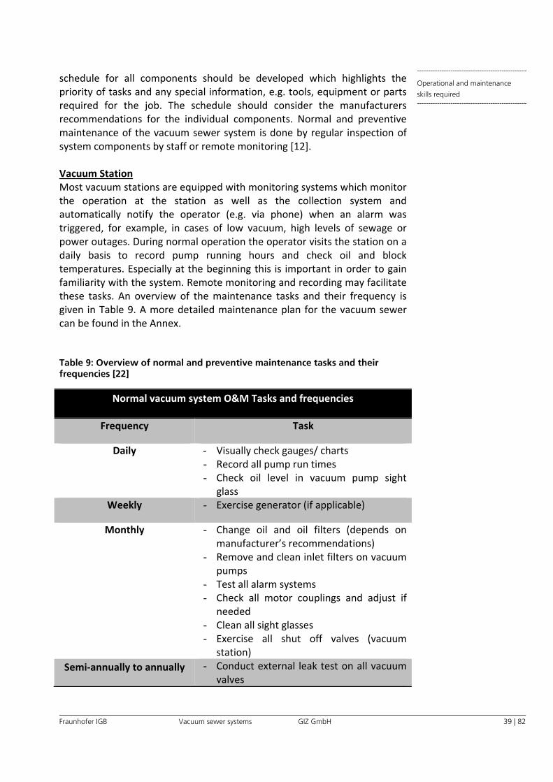
Fraunhofer IGB Vacuum sewer systems GIZ GmbH 39 | 82
Operational and maintenance
skills required
schedule for all components should be developed which highlights the priority of tasks and any special information, e.g. tools, equipment or parts required for the job. The schedule should consider the manufacturers recommendations for the individual components. Normal and preventive maintenance of the vacuum sewer system is done by regular inspection of system components by staff or remote monitoring [12]. Vacuum Station Most vacuum stations are equipped with monitoring systems which monitor the operation at the station as well as the collection system and automatically notify the operator (e.g. via phone) when an alarm was triggered, for example, in cases of low vacuum, high levels of sewage or power outages. During normal operation the operator visits the station on a daily basis to record pump running hours and check oil and block temperatures. Especially at the beginning this is important in order to gain familiarity with the system. Remote monitoring and recording may facilitate these tasks. An overview of the maintenance tasks and their frequency is given in Table 9. A more detailed maintenance plan for the vacuum sewer can be found in the Annex. Table 9: Overview of normal and preventive maintenance tasks and their frequencies [22]
Normal vacuum system O&M Tasks and frequencies
Frequency Task
Daily - Visually check gauges/ charts - Record all pump run times - Check oil level in vacuum pump sight
glass Weekly - Exercise generator (if applicable)
Monthly - Change oil and oil filters (depends on manufacturer’s recommendations)
- Remove and clean inlet filters on vacuum pumps
- Test all alarm systems - Check all motor couplings and adjust if
needed - Clean all sight glasses - Exercise all shut off valves (vacuum
station)
Semi‐annually to annually - Conduct external leak test on all vacuum valves
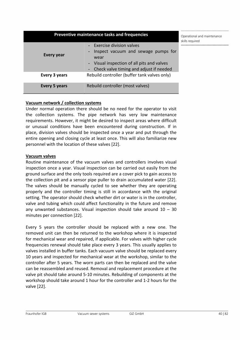
Fraunhofer IGB Vacuum sewer systems GIZ GmbH 40 | 82
Operational and maintenance
skills required
Preventive maintenance tasks and frequencies
Every year
- Exercise division valves - Inspect vacuum and sewage pumps for
wear - Visual inspection of all pits and valves - Check valve timing and adjust if needed
Every 3 years Rebuild controller (buffer tank valves only)
Every 5 years Rebuild controller (most valves)
Vacuum network / collection systems Under normal operation there should be no need for the operator to visit the collection systems. The pipe network has very low maintenance requirements. However, it might be desired to inspect areas where difficult or unusual conditions have been encountered during construction. If in place, division valves should be inspected once a year and put through the entire opening and closing cycle at least once. This will also familiarize new personnel with the location of these valves [22]. Vacuum valves Routine maintenance of the vacuum valves and controllers involves visual inspection once a year. Visual inspection can be carried out easily from the ground surface and the only tools required are a cover pick to gain access to the collection pit and a sensor pipe puller to drain accumulated water [22]. The valves should be manually cycled to see whether they are operating properly and the controller timing is still in accordance with the original setting. The operator should check whether dirt or water is in the controller, valve and tubing which could affect functionality in the future and remove any unwanted substances. Visual inspection should take around 10 – 30 minutes per connection [22]. Every 5 years the controller should be replaced with a new one. The removed unit can then be returned to the workshop where it is inspected for mechanical wear and repaired, if applicable. For valves with higher cycle frequencies renewal should take place every 3 years. This usually applies to valves installed in buffer tanks. Each vacuum valve should be replaced every 10 years and inspected for mechanical wear at the workshop, similar to the controller after 5 years. The worn parts can then be replaced and the valve can be reassembled and reused. Removal and replacement procedure at the valve pit should take around 5‐10 minutes. Rebuilding of components at the workshop should take around 1 hour for the controller and 1‐2 hours for the valve [22].
Fraunhofer IGB Vacuum sewer systems GIZ GmbH 41 | 82
Operational and maintenance
skills required
6.2. Emergency maintenance The vacuum sewer system has recommended maintenance tasks and in case of a failure there is a troubleshooting method to track the failure. Modern systems are usually equipped with a set of alarms which inform the operator of the fault via a mobile phone. Emergency incidents can occur anytime of the day requiring personnel to resolve the problem after working hours on an overtime basis. Emergency or breakdown maintenance can occur at the vacuum valve, the vacuum station or the pipe network. Vacuum station If the preventive maintenance measures described above are carried out accordingly there are very few emergencies that occur at the vacuum station. However, most systems are designed in a way that redundancy allows for a lot of time before the fault affects the normal operation. The number of pumps is selected so that the system continues to work normally with one pump offline. Thus, the operator has enough time to identify the problem and recondition the pump (e.g. replace parts etc.). Further, the vacuum tank is designed to have sufficient capacity to accept sewage while the wastewater pumps are out of service, for example during a power blackout. The vacuum tank also functions as a vacuum buffer for the collection system. This way, drops in system vacuum are slowed down giving the operator more time to recondition the system. Backup electricity supply, such as a generator or a connection for quick deployment of an external power source, should be provided as well as a procedure how to restore power in cases of power blackouts [22]. Emergencies related to power blackouts are rare but the most common faults at the vacuum station. Other faults may involve clogging of the wastewater pumps. The operator needs to have adequate skills to identify and solve faults in a timely manner. Vacuum network / collection system If the design and construction of the pipe network has been carried out properly there are few things that can lead to emergencies affecting the collection system. The high transport velocities of wastewater minimise the precipitation and scaling of solids. For systems with separated black water streams this risk is increased and needs to be addressed. But since most vacuum sewers transport mixed wastewater the greatest risk for the vacuum collection system arises from landslides or excavations for other utilities. When these events result in line breaks system vacuum will be lost. If the incident is not reported by the utilities the operator can isolate different lines and localise the defective section by closing and opening division valves along the piping route in a logical manner [22]. Additionally, the operator can use the inspection valves and check for vacuum conditions in various sections. However, any rupture or damage to the pipe network needs to be resolved in a timely fashion most likely by exchanging the affected pipe. Collaboration with the impact causing entity may facilitate
Fraunhofer IGB Vacuum sewer systems GIZ GmbH 42 | 82
Operational and maintenance
skills required
and accelerate reconditioning, especially since the excavation machines are already at the site. Vacuum valves Most service calls related to the vacuum valves are caused by the users. Around 70% of faults result from flushing objects that lead to clogging in the valve or other parts of the pipework in the collection pit [11]. Other faults are caused by extraneous water for example from rainwater entering the pit and damaging the controller or mechanical wear of valve components. In most cases maintenance is fairly simple. The controller is taken out, dried and reinstalled. The operator needs to initiate action so that the design error of water entering the pit is corrected. Waterproof controllers are also available however it is undesirable to have stormwater entering the collection pit. Exchanging a faulty valve is relatively simple and can be completed within 10‐15 minutes by a single person [11]. But where no remote monitoring is installed emergency maintenance usually requires more than one person to locate the affected valve pit using the inspection valves. This can be difficult and adequate training of the personnel is imperative. The faulty valve is then taken back to the workshop where it is rebuilt and made fit for reuse. Since valve failures can cause failures in other parts of the system it is crucial that the operator is capable of identifying and resolving any emerging issues quickly. If the vacuum pumps cannot keep up with the loss of vacuum then other valves will have insufficient vacuum to perform their function. This can lead to backups which possibly result in waterlogging since an increased amount of sewage will have to be transported at a changed, possibly inadequate, water to air ratio when vacuum is restored [22]. The design, construction and operation of the system affect the maintenance. In many cases it can be advisable to develop a maintenance agreement with the system provider to ensure adequate maintenance and advisory services [11]. This especially applies to municipalities or regions that have no or little experience with operating and maintaining vacuum sewers. The maintenance agreement increases operational safety and reliability and ensures that local operating personnel is trained accordingly. Since a high degree of technical knowledge is required the project should budget 3‐6 months on‐site training [22].
6.3. Record keeping Proper record keeping of operational data, performed maintenance and incidents is imperative to successfully operate and maintain vacuum sewers. A crucial step to short‐term and long‐term troubleshooting alike is the analysis of records. The more comprehensive the records the more valuable they are for troubleshooting and system optimisation. Most systems have electronic, computer assisted, automated data recording systems e.g. for
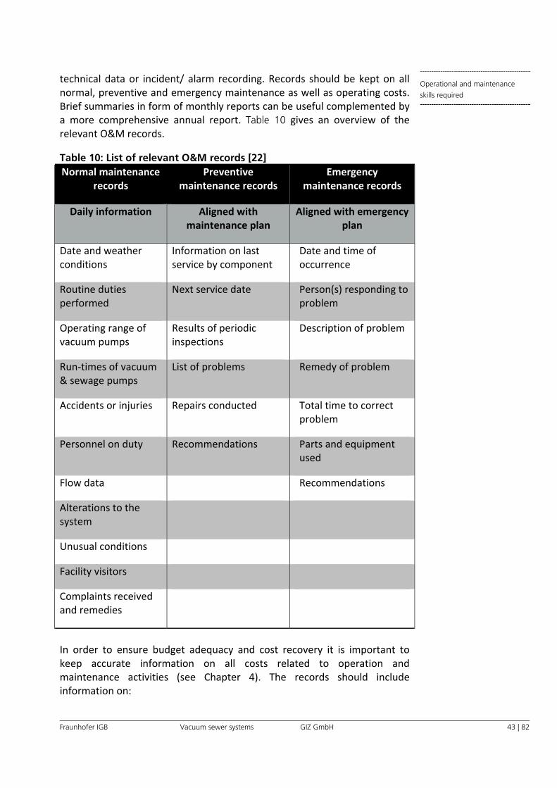
Fraunhofer IGB Vacuum sewer systems GIZ GmbH 43 | 82
Operational and maintenance
skills required
technical data or incident/ alarm recording. Records should be kept on all normal, preventive and emergency maintenance as well as operating costs. Brief summaries in form of monthly reports can be useful complemented by a more comprehensive annual report. Table 10 gives an overview of the relevant O&M records.
Table 10: List of relevant O&M records [22]
Normal maintenance records
Preventive maintenance records
Emergency maintenance records
Daily information Aligned with maintenance plan
Aligned with emergency plan
Date and weather conditions
Information on last service by component
Date and time of occurrence
Routine duties performed
Next service date Person(s) responding to problem
Operating range of vacuum pumps
Results of periodic inspections
Description of problem
Run‐times of vacuum & sewage pumps
List of problems Remedy of problem
Accidents or injuries Repairs conducted Total time to correct problem
Personnel on duty Recommendations Parts and equipment used
Flow data Recommendations
Alterations to the system
Unusual conditions
Facility visitors
Complaints received and remedies
In order to ensure budget adequacy and cost recovery it is important to keep accurate information on all costs related to operation and maintenance activities (see Chapter 4). The records should include information on:
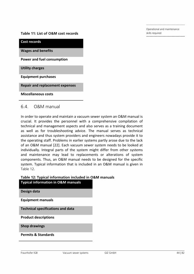
Fraunhofer IGB Vacuum sewer systems GIZ GmbH 44 | 82
Operational and maintenance
skills required
Table 11: List of O&M cost records
Cost records
Wages and benefits
Power and fuel consumption
Utility charges
Equipment purchases
Repair and replacement expenses
Miscellaneous costs
6.4. O&M manual
In order to operate and maintain a vacuum sewer system an O&M manual is crucial. It provides the personnel with a comprehensive compilation of technical and management aspects and also serves as a training document as well as for troubleshooting advice. The manual serves as technical assistance and thus system providers and engineers nowadays provide it to the operating staff. Problems in earlier systems partly arose due to the lack of an O&M manual [22]. Each vacuum sewer system needs to be looked at individually. Integral parts of the system might differ from other systems and maintenance may lead to replacements or alterations of system components. Thus, an O&M manual needs to be designed for the specific system. Typical information that is included in an O&M manual is given in Table 12.
Table 12: Typical information included in O&M manuals
Typical information in O&M manuals
Design data
Equipment manuals
Technical specifications and data
Product descriptions
Shop drawings
Permits & Standards
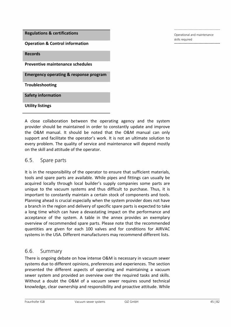
Fraunhofer IGB Vacuum sewer systems GIZ GmbH 45 | 82
Operational and maintenance
skills required
Regulations & certifications
Operation & Control information
Records
Preventive maintenance schedules
Emergency operating & response program
Troubleshooting
Safety information
Utility listings
A close collaboration between the operating agency and the system provider should be maintained in order to constantly update and improve the O&M manual. It should be noted that the O&M manual can only support and facilitate the operator’s work. It is not an ultimate solution to every problem. The quality of service and maintenance will depend mostly on the skill and attitude of the operator.
6.5. Spare parts
It is in the responsibility of the operator to ensure that sufficient materials, tools and spare parts are available. While pipes and fittings can usually be acquired locally through local builder’s supply companies some parts are unique to the vacuum systems and thus difficult to purchase. Thus, it is important to constantly maintain a certain stock of components and tools. Planning ahead is crucial especially when the system provider does not have a branch in the region and delivery of specific spare parts is expected to take a long time which can have a devastating impact on the performance and acceptance of the system. A table in the annex provides an exemplary overview of recommended spare parts. Please note that the recommended quantities are given for each 100 valves and for conditions for AIRVAC systems in the USA. Different manufacturers may recommend different lists.
6.6. Summary There is ongoing debate on how intense O&M is necessary in vacuum sewer systems due to different opinions, preferences and experiences. The section presented the different aspects of operating and maintaining a vacuum sewer system and provided an overview over the required tasks and skills. Without a doubt the O&M of a vacuum sewer requires sound technical knowledge, clear ownership and responsibility and proactive attitude. While
Fraunhofer IGB Vacuum sewer systems GIZ GmbH 46 | 82
User friendliness good design can facilitate O&M, adequate training of operators is imperative. Adequate planning of maintenance activities, sufficient spare parts stocks, the development of a maintenance plan, thorough record keeping and troubleshooting systems are crucial for the sustainable operation of a vacuum sewer system.
7. User friendliness
The vacuum sewer system contains mechanical and electrical components which require supervision and management. Generally, the more technological components a system has the more prone it is to failures and therefore needs more attention. Vacuum sewer systems can facilitate the wastewater service provision in many ways. First of all, the operator can identify system failures very easily. As the differential pressure generated by the vacuum pumps is the driving force of wastewater transport any leaks in the transmission lines or damages to the valve units result in the increase of pump running time and energy consumption which can be observed at the vacuum station and can even be monitored in real‐time using online monitoring and communication tools. Thus, technical staff can quickly identify and resolve system failures.
A special feature of the vacuum system is the fact that it is a closed system. Thus, exfiltration into the environment is very unlikely. Exfiltration would be caused by leaks or ruptures along the conduits in other sewer systems, but as the vacuum system is under lower pressure than the environment, no exfiltration can occur. However, any leaks would make it very difficult for the vacuum pumps to generate sufficient vacuum in the system due to the inflowing air. In absence of differential pressure no wastewater can be transported. This is the main reason why vacuum lines can be placed in the same trenches as the drinking water mains and that makes it suitable for water protection areas or areas with high‐groundwater tables. These features facilitate installation and servicing of the network for every stakeholder, especially when the water service provider is the same entity as the wastewater service provider which very often is the case.
Although damages to the pipes can occur they remain very rare. In a comparative study Kruk [23] found that more than 80 % of failures in the vacuum system occur at the collection chambers (valve pits) (Figure 15) and only few are reported for the conduits. The most frequent failures at the collection chambers were associated with the opening and closing mechanisms of the valve and flooding of the valve control unit (92 %). These failures are most likely to be caused by inadequate user behaviour, such as flushing of objects which are too big to pass the valve or which can damage the valve components (e.g. sharp objects can pierce the membrane). The study by Günthert [11] confirms this. The researchers concluded that 70% of all blockages are caused by users flushing objects which damage the valve or
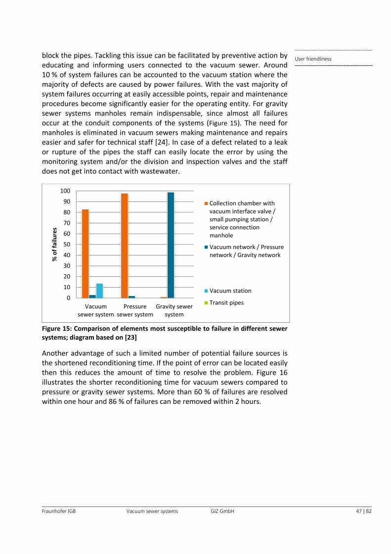
Fraunhofer IGB Vacuum sewer systems GIZ GmbH 47 | 82
User friendliness block the pipes. Tackling this issue can be facilitated by preventive action by educating and informing users connected to the vacuum sewer. Around 10 % of system failures can be accounted to the vacuum station where the majority of defects are caused by power failures. With the vast majority of system failures occurring at easily accessible points, repair and maintenance procedures become significantly easier for the operating entity. For gravity sewer systems manholes remain indispensable, since almost all failures occur at the conduit components of the systems (Figure 15). The need for manholes is eliminated in vacuum sewers making maintenance and repairs easier and safer for technical staff [24]. In case of a defect related to a leak or rupture of the pipes the staff can easily locate the error by using the monitoring system and/or the division and inspection valves and the staff does not get into contact with wastewater.
Figure 15: Comparison of elements most susceptible to failure in different sewer systems; diagram based on [23]
Another advantage of such a limited number of potential failure sources is the shortened reconditioning time. If the point of error can be located easily then this reduces the amount of time to resolve the problem. Figure 16 illustrates the shorter reconditioning time for vacuum sewers compared to pressure or gravity sewer systems. More than 60 % of failures are resolved within one hour and 86 % of failures can be removed within 2 hours.
0
10
20
30
40
50
60
70
80
90
100
Vacuumsewer system
Pressuresewer system
Gravity sewersystem
% of failu
res
Collection chamber withvacuum interface valve /small pumping station /service connectionmanhole
Vacuum network / Pressurenetwork / Gravity network
Vacuum station
Transit pipes
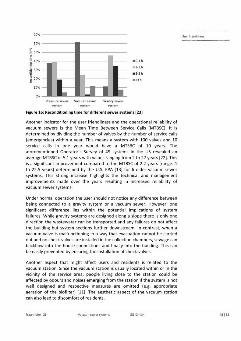
Fraunhofer IGB Vacuum sewer systems GIZ GmbH 48 | 82
User friendliness
Figure 16: Reconditioning time for different sewer systems [23]
Another indicator for the user friendliness and the operational reliability of vacuum sewers is the Mean Time Between Service Calls (MTBSC). It is determined by dividing the number of valves by the number of service calls (emergencies) within a year. This means a system with 100 valves and 10 service calls in one year would have a MTSBC of 10 years. The aforementioned Operator’s Survey of 49 systems in the US revealed an average MTBSC of 5.1 years with values ranging from 2 to 27 years [22]. This is a significant improvement compared to the MTBSC of 2.2 years (range: 1 to 22.5 years) determined by the U.S. EPA [13] for 6 older vacuum sewer systems. This strong increase highlights the technical and management improvements made over the years resulting in increased reliability of vacuum sewer systems.
Under normal operation the user should not notice any difference between being connected to a gravity system or a vacuum sewer. However, one significant difference lies within the potential implications of system failures. While gravity systems are designed along a slope there is only one direction the wastewater can be transported and any failures do not affect the building but system sections further downstream. In contrast, when a vacuum valve is malfunctioning in a way that evacuation cannot be carried out and no check‐valves are installed in the collection chambers, sewage can backflow into the house connections and finally into the building. This can be easily prevented by ensuring the installation of check‐valves.
Another aspect that might affect users and residents is related to the vacuum station. Since the vacuum station is usually located within or in the vicinity of the service area, people living close to the station could be affected by odours and noises emerging from the station if the system is not well designed and respective measures are omitted (e.g. appropriate aeration of the biofilter) [11]. The aesthetic aspect of the vacuum station can also lead to discomfort of residents.
Fraunhofer IGB Vacuum sewer systems GIZ GmbH 49 | 82
Cases for application QUICK PICKS:
- Faults in vacuum sewers mainly occur at the vacuum valves and the station => easily accessible and thus safer and more hygienic for operational staff
- Localisation of faults quickly possible = > Short reconditioning time
- Odour and noise from vacuum station are main concerns for residents
8. Cases for application
The chapters above present the technical aspects of a vacuum sewer network. The differences between conventional gravity sewers and vacuum sewers are quite significant. Thus, the ‘alternative wastewater collection system’ has its strengths in other areas of application than the gravity sewer concept.
In vacuum sewers the driving mechanism is air rather than water. Thus, less water is required to convey the sewage to the treatment plant. This makes the vacuum technology a good choice in water scarce regions where water saving has great impact. Gravity based sewers require larger water quantities to wash away all the waste contained in sewage. This is the reason why combined sewers also collect storm water. Where separation into sanitary sewer and storm water drainage is desired (or required) vacuum sewers are a good choice since they can transport wastewater efficiently with little water. The role of vacuum sewer in integrated water management concepts is described in more detail in Chapter 10.
Besides requiring a significant amount of water gravity sewers face the challenge to rely on a constant slope of minimum 2%. If the gradient cannot be provided by the terrain conditions, excavations have to reach very deep. Additional lift stations might be required to elevate the wastewater to higher levels into a new pipe section which once again provides sufficient slope. This is a common problem in areas with flat terrain. High groundwater tables can also pose a challenge to the construction of a gravity sewer since dewatering might be required during construction. Since vacuum sewers do not rely on gravity and differential pressure is the driving force of transportation they are very suitable for flat areas. Vacuum sewers can even accommodate small inclinations and overcome small height. And since the lines can be placed in low depths vacuum sewers are also suitable for areas where high groundwater and rocky or sandy soil conditions pose challenges to deep excavation.
This advantage of shallower and less complicated excavations has a significant cost saving potential. Additional savings can be achieved through
Fraunhofer IGB Vacuum sewer systems GIZ GmbH 50 | 82
Reference projects the shorter construction period. Municipalities which face budget constraints but require an investment in their wastewater infrastructure might find the option of a vacuum sewer attractive.
A significant characteristic of the vacuum sewer system is the fact that exfiltration is detected immediately. The system is closed and tight and any leak will directly result in loss of vacuum and increased pump runtime which is noticed by the operator. Larger damages can even result in a total stop of sewage transport. Vacuum lines are considered safe enough to be placed in the same trench as drinking water lines. Leakages in conventional sewer systems often go unnoticed and untreated sewage leaks into the environment. Elaborate and costly measures are necessary to minimise the risk of exfiltration for conventional systems. The environmental safety of the vacuum sewer makes it a good choice for ecologically sensitive areas as well as areas with protected groundwater resources.
In gravity sewers, infiltration of stormwater and groundwater is a frequent issue as well. Thus, clean water is mixed with the sewage and increases the costs for wastewater treatment significantly. As the vacuum sewer system has to be tight to operate, infiltration should not occur. Therefore this system has advantages in areas with high groundwater table and areas prone to flooding.
Exemplary cases for application include coastal areas which are often characterised by flat terrain and high groundwater tables. Thus, vacuum sewer systems can pose a viable sewer option for coastal communities.
Another application can be found in the drainage of seasonal settlements such as recreation areas, camping sites etc. where the number of dischargers varies over the year. Gravity based systems face the problem of sedimentation if the line is not flushed regularly. Due to the high transport velocities this is not a problem in vacuum sewers making it a good choice for seasonal operation.
9. Reference projects
Vacuum sewer projects have gained increasing interest over the years. The first modern systems were implemented in the 1970s and the number is constantly growing. Growing operational experience and increasing awareness on the strengths of this sewer alternative has led to a growing number of implemented vacuum sewer projects. Figure 17 displays the number of projects in several countries realised by the two biggest system providers, AIRVAC and ROEDIGER, until the year 2008. The majority of systems have been implemented in USA and Germany followed by Japan, France, the UK, Australia, Czech Republic and Poland. Additional projects have been realised since then. The other aforementioned manufacturers have also realised many projects in many parts of the world.
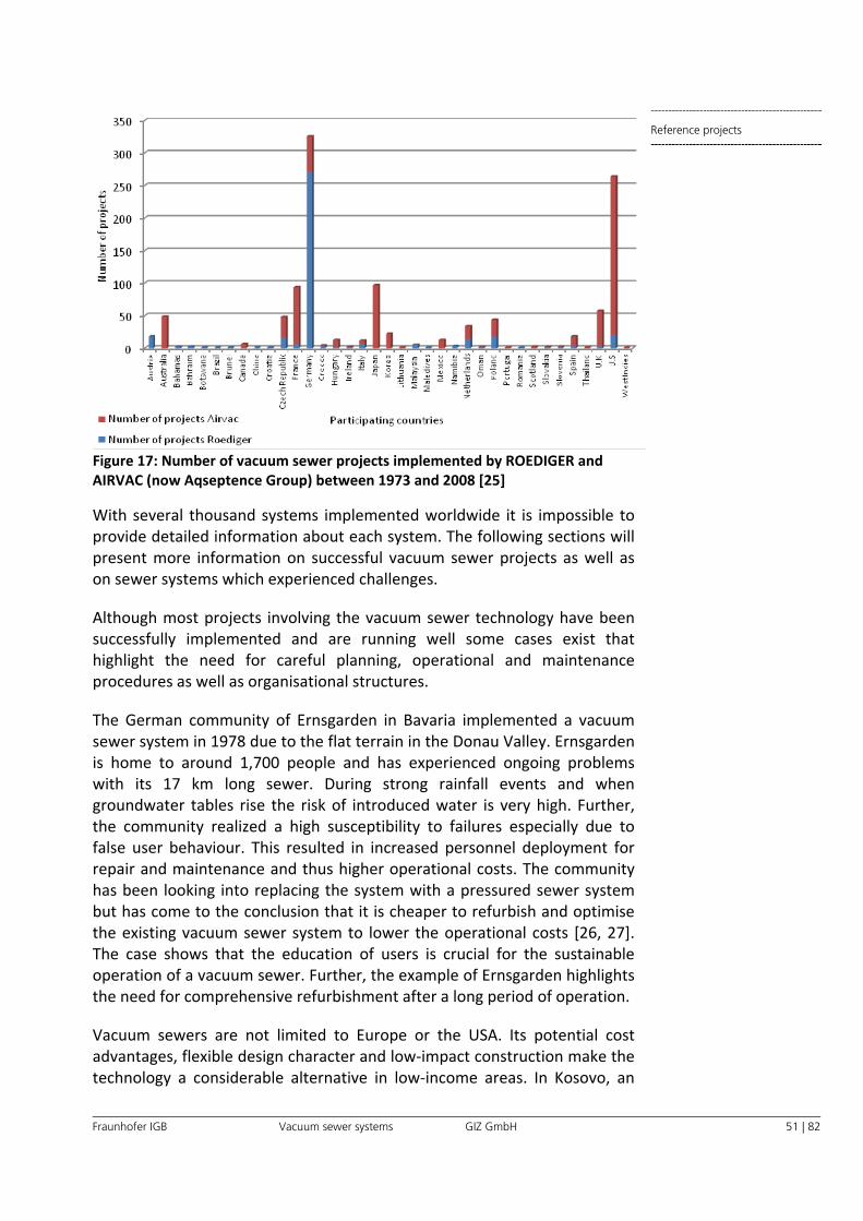
Fraunhofer IGB Vacuum sewer systems GIZ GmbH 51 | 82
Reference projects
Figure 17: Number of vacuum sewer projects implemented by ROEDIGER and AIRVAC (now Aqseptence Group) between 1973 and 2008 [25]
With several thousand systems implemented worldwide it is impossible to provide detailed information about each system. The following sections will present more information on successful vacuum sewer projects as well as on sewer systems which experienced challenges.
Although most projects involving the vacuum sewer technology have been successfully implemented and are running well some cases exist that highlight the need for careful planning, operational and maintenance procedures as well as organisational structures.
The German community of Ernsgarden in Bavaria implemented a vacuum sewer system in 1978 due to the flat terrain in the Donau Valley. Ernsgarden is home to around 1,700 people and has experienced ongoing problems with its 17 km long sewer. During strong rainfall events and when groundwater tables rise the risk of introduced water is very high. Further, the community realized a high susceptibility to failures especially due to false user behaviour. This resulted in increased personnel deployment for repair and maintenance and thus higher operational costs. The community has been looking into replacing the system with a pressured sewer system but has come to the conclusion that it is cheaper to refurbish and optimise the existing vacuum sewer system to lower the operational costs [26, 27]. The case shows that the education of users is crucial for the sustainable operation of a vacuum sewer. Further, the example of Ernsgarden highlights the need for comprehensive refurbishment after a long period of operation.
Vacuum sewers are not limited to Europe or the USA. Its potential cost advantages, flexible design character and low‐impact construction make the technology a considerable alternative in low‐income areas. In Kosovo, an
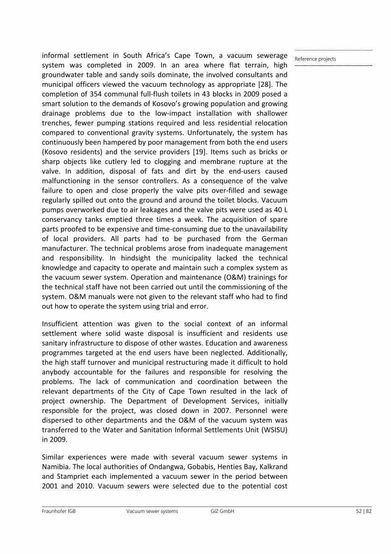
Fraunhofer IGB Vacuum sewer systems GIZ GmbH 52 | 82
Reference projects informal settlement in South Africa’s Cape Town, a vacuum sewerage system was completed in 2009. In an area where flat terrain, high groundwater table and sandy soils dominate, the involved consultants and municipal officers viewed the vacuum technology as appropriate [28]. The completion of 354 communal full‐flush toilets in 43 blocks in 2009 posed a smart solution to the demands of Kosovo’s growing population and growing drainage problems due to the low‐impact installation with shallower trenches, fewer pumping stations required and less residential relocation compared to conventional gravity systems. Unfortunately, the system has continuously been hampered by poor management from both the end users (Kosovo residents) and the service providers [19]. Items such as bricks or sharp objects like cutlery led to clogging and membrane rupture at the valve. In addition, disposal of fats and dirt by the end‐users caused malfunctioning in the sensor controllers. As a consequence of the valve failure to open and close properly the valve pits over‐filled and sewage regularly spilled out onto the ground and around the toilet blocks. Vacuum pumps overworked due to air leakages and the valve pits were used as 40 L conservancy tanks emptied three times a week. The acquisition of spare parts proofed to be expensive and time‐consuming due to the unavailability of local providers. All parts had to be purchased from the German manufacturer. The technical problems arose from inadequate management and responsibility. In hindsight the municipality lacked the technical knowledge and capacity to operate and maintain such a complex system as the vacuum sewer system. Operation and maintenance (O&M) trainings for the technical staff have not been carried out until the commissioning of the system. O&M manuals were not given to the relevant staff who had to find out how to operate the system using trial and error.
Insufficient attention was given to the social context of an informal settlement where solid waste disposal is insufficient and residents use sanitary infrastructure to dispose of other wastes. Education and awareness programmes targeted at the end users have been neglected. Additionally, the high staff turnover and municipal restructuring made it difficult to hold anybody accountable for the failures and responsible for resolving the problems. The lack of communication and coordination between the relevant departments of the City of Cape Town resulted in the lack of project ownership. The Department of Development Services, initially responsible for the project, was closed down in 2007. Personnel were dispersed to other departments and the O&M of the vacuum system was transferred to the Water and Sanitation Informal Settlements Unit (WSISU) in 2009.
Similar experiences were made with several vacuum sewer systems in Namibia. The local authorities of Ondangwa, Gobabis, Henties Bay, Kalkrand and Stampriet each implemented a vacuum sewer in the period between 2001 and 2010. Vacuum sewers were selected due to the potential cost
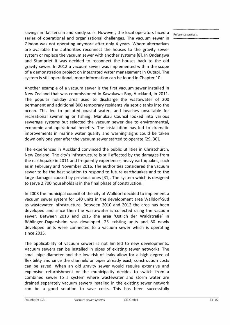
Fraunhofer IGB Vacuum sewer systems GIZ GmbH 53 | 82
Reference projects savings in flat terrain and sandy soils. However, the local operators faced a series of operational and organisational challenges. The vacuum sewer in Gibeon was not operating anymore after only 4 years. Where alternatives are available the authorities reconnect the houses to the gravity sewer system or replace the vacuum sewer with another systems [8]. In Ondangwa and Stampriet it was decided to reconnect the houses back to the old gravity sewer. In 2012 a vacuum sewer was implemented within the scope of a demonstration project on integrated water management in Outapi. The system is still operational; more information can be found in Chapter 10.
Another example of a vacuum sewer is the first vacuum sewer installed in New Zealand that was commissioned in Kawakawa Bay, Auckland, in 2011. The popular holiday area used to discharge the wastewater of 200 permanent and additional 800 temporary residents via septic tanks into the ocean. This led to polluted coastal waters and beaches unsuitable for recreational swimming or fishing. Manukau Council looked into various sewerage systems but selected the vacuum sewer due to environmental, economic and operational benefits. The installation has led to dramatic improvements in marine water quality and warning signs could be taken down only one year after the vacuum sewer started to operate [29, 30].
The experiences in Auckland convinced the public utilities in Christchurch, New Zealand. The city’s infrastructure is still affected by the damages from the earthquake in 2011 and frequently experiences heavy earthquakes, such as in February and November 2016. The authorities considered the vacuum sewer to be the best solution to respond to future earthquakes and to the large damages caused by previous ones [31]. The system which is designed to serve 2,700 households is in the final phase of construction.
In 2008 the municipal council of the city of Walldorf decided to implement a vacuum sewer system for 140 units in the development area Walldorf‐Süd as wastewater infrastructure. Between 2010 and 2012 the area has been developed and since then the wastewater is collected using the vacuum sewer. Between 2013 and 2015 the area ‘Östlich der Waldstraße’ in Böblingen‐Dagersheim was developed. 25 existing units and 80 newly developed units were connected to a vacuum sewer which is operating since 2015.
The applicability of vacuum sewers is not limited to new developments. Vacuum sewers can be installed in pipes of existing sewer networks. The small pipe diameter and the low risk of leaks allow for a high degree of flexibility and since the channels or pipes already exist, construction costs can be saved. When an old gravity sewer would require extensive and expensive refurbishment or the municipality decides to switch from a combined sewer to a system where wastewater and storm water are drained separately vacuum sewers installed in the existing sewer network can be a good solution to save costs. This has been successfully
Fraunhofer IGB Vacuum sewer systems GIZ GmbH 54 | 82
Vacuum sewers as part of an
integrated water management
concept
implemented in the small German municipality Schwalmtal – Rainrod with 140 connections and the system is operating since 2011 [32].
Figure 18: Vacuum pipe installed in existing channels; the PE pipe is attached to the wall of the channel [32].
When a combined sewer is replaced by a vacuum sewer network the challenge arises that the existing water infrastructure at the house needs to be separated since wastewater and rain water feed into the same pipes. The rain gutter is usually connected to the house connection under the building which leads to the sewer. This is a challenge in already developed areas when existing dwellings are connected to a vacuum sewer. Every house connection needs to be surveyed individually at all access points [33] and a new pathway for storm water flow is required while on the other hand the wastewater will be directed to the vacuum pit.
10 Vacuum sewers as part of an integrated water
management concept Efforts to recycle water, energy and nutrients from wastewater streams have been subject to research worldwide and numerous demonstration projects have been implemented. The vacuum sewer system is considered as a suitable option in order to separate wastewater at the source. Especially when targeting nutrient recovery from wastewater streams it is essential to concentrate nutrient rich waters, such as black water from household toilets or other sources with high nutrient load, in order to increase efficiency of the recycling process. The same applies to the process of energy recovery from wastewater. The higher the organic load of the wastewater the higher is the energy yield (most commonly in form of biogas). Therefore it is crucial to find ways of separating the different
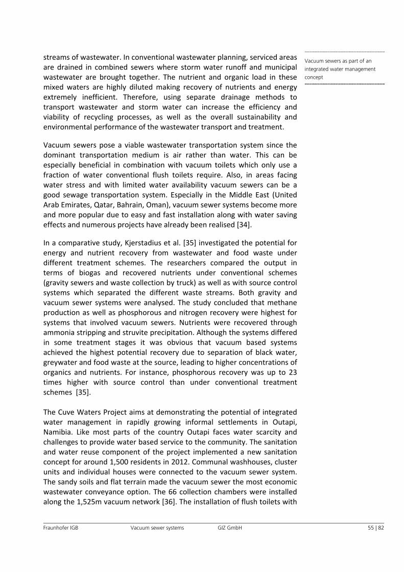
Fraunhofer IGB Vacuum sewer systems GIZ GmbH 55 | 82
Vacuum sewers as part of an
integrated water management
concept
streams of wastewater. In conventional wastewater planning, serviced areas are drained in combined sewers where storm water runoff and municipal wastewater are brought together. The nutrient and organic load in these mixed waters are highly diluted making recovery of nutrients and energy extremely inefficient. Therefore, using separate drainage methods to transport wastewater and storm water can increase the efficiency and viability of recycling processes, as well as the overall sustainability and environmental performance of the wastewater transport and treatment.
Vacuum sewers pose a viable wastewater transportation system since the dominant transportation medium is air rather than water. This can be especially beneficial in combination with vacuum toilets which only use a fraction of water conventional flush toilets require. Also, in areas facing water stress and with limited water availability vacuum sewers can be a good sewage transportation system. Especially in the Middle East (United Arab Emirates, Qatar, Bahrain, Oman), vacuum sewer systems become more and more popular due to easy and fast installation along with water saving effects and numerous projects have already been realised [34].
In a comparative study, Kjerstadius et al. [35] investigated the potential for energy and nutrient recovery from wastewater and food waste under different treatment schemes. The researchers compared the output in terms of biogas and recovered nutrients under conventional schemes (gravity sewers and waste collection by truck) as well as with source control systems which separated the different waste streams. Both gravity and vacuum sewer systems were analysed. The study concluded that methane production as well as phosphorous and nitrogen recovery were highest for systems that involved vacuum sewers. Nutrients were recovered through ammonia stripping and struvite precipitation. Although the systems differed in some treatment stages it was obvious that vacuum based systems achieved the highest potential recovery due to separation of black water, greywater and food waste at the source, leading to higher concentrations of organics and nutrients. For instance, phosphorous recovery was up to 23 times higher with source control than under conventional treatment schemes [35]. The Cuve Waters Project aims at demonstrating the potential of integrated water management in rapidly growing informal settlements in Outapi, Namibia. Like most parts of the country Outapi faces water scarcity and challenges to provide water based service to the community. The sanitation and water reuse component of the project implemented a new sanitation concept for around 1,500 residents in 2012. Communal washhouses, cluster units and individual houses were connected to the vacuum sewer system. The sandy soils and flat terrain made the vacuum sewer the most economic wastewater conveyance option. The 66 collection chambers were installed along the 1,525m vacuum network [36]. The installation of flush toilets with
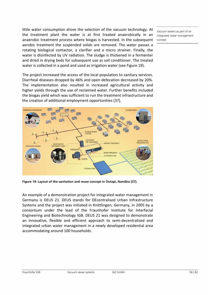
Fraunhofer IGB Vacuum sewer systems GIZ GmbH 56 | 82
Vacuum sewers as part of an
integrated water management
concept
little water consumption drove the selection of the vacuum technology. At the treatment plant the water is at first treated anaerobically in an anaerobic treatment process where biogas is harvested. In the subsequent aerobic treatment the suspended solids are removed. The water passes a rotating biological contactor, a clarifier and a micro strainer. Finally, the water is disinfected by UV radiation. The sludge is thickened in a fermenter and dried in drying beds for subsequent use as soil conditioner. The treated water is collected in a pond and used as irrigation water (see Figure 19).
The project increased the access of the local population to sanitary services. Diarrheal diseases dropped by 46% and open defecation decreased by 20%. The implementation also resulted in increased agricultural activity and higher yields through the use of reclaimed water. Further benefits included the biogas yield which was sufficient to run the treatment infrastructure and the creation of additional employment opportunities [37].
Figure 19: Layout of the sanitation and reuse concept in Outapi, Namibia [37].
An example of a demonstration project for integrated water management in Germany is DEUS 21. DEUS stands for DEcentralised Urban Infrastructure Systems and the project was initiated in Knittlingen, Germany, in 2005 by a consortium under the lead of the Fraunhofer Institute for Interfacial Engineering and Biotechnology IGB. DEUS 21 was designed to demonstrate an innovative, flexible and efficient approach to semi‐decentralised and integrated urban water management in a newly developed residential area accommodating around 100 households.
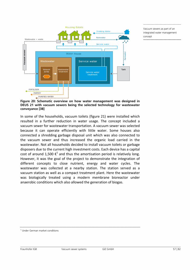
Fraunhofer IGB Vacuum sewer systems GIZ GmbH 57 | 82
Vacuum sewers as part of an
integrated water management
concept
Figure 20: Schematic overview on how water management was designed in DEUS 21 with vacuum sewers being the selected technology for wastewater conveyance [38]
In some of the households, vacuum toilets (figure 21) were installed which resulted in a further reduction in water usage. The concept included a vacuum sewer for wastewater transportation. A vacuum sewer was selected because it can operate efficiently with little water. Some houses also connected a shredding garbage disposal unit which was also connected to the vacuum sewer and thus increased the organic load carried in the wastewater. Not all households decided to install vacuum toilets or garbage disposers due to the current high investment costs. Each device has a capital cost of around 1,500 €1 and thus the amortisation period is relatively long. However, it was the goal of the project to demonstrate the integration of different concepts to close nutrient, energy and water cycles. The wastewater was collected at a nearby station. The station served as a vacuum station as well as a compact treatment plant. Here the wastewater was biologically treated using a modern membrane bioreactor under anaerobic conditions which also allowed the generation of biogas.
1 Under German market conditions
Fraunhofer IGB Vacuum sewer systems GIZ GmbH 58 | 82
Vacuum sewers as part of an
integrated water management
concept
One of the earliest projects involving vacuum sewers in integrated water management was implemented in Lübeck‐Flintenbreite in Northern Germany in 2000. 30 residential units have been constructed for around 116 residents. The concept is designed to allow an integrative holistic approach to infrastructure services with a focus on water and wastewater infrastructure. The houses are equipped with vacuum toilets which require only 0.7‐1.2 L per flush. After initial problems the users adopted the vacuum toilets very well. The water consumption per capita in Flintenbreite is well below the average water consumption in Germany. Additionally, shredders were installed in the kitchens and together with the black water from the toilets the organic waste is transported to a local treatment facility via a vacuum sewer network. At the treatment facility biogas is generated and used for local electricity and heat provision. The greywater from kitchen, bathrooms etc. is transported to a constructed wetland where it is treated and eventually discharged to a local creek [39, 40].
The city of Pfaffenhofen an der Ilm designed a mixed residential area for ecologically and socially healthy living conditions. The project is currently under construction. The so‐called Eco‐Quarter aims at using modern concepts of energy and water management. A key component of the project is the vacuum sewer system as it facilitates the separation of different wastewater streams. The network is 4 km long and designed to serve 1,100 people plus the connected small commercial area. The system includes a new type of collection pit where black water and grey water are separately collected in the same vacuum pit (Figure 22). Greywater will be transported to a constructed wetland where it is treated for subsequent reuse in
Figure 21: Left: Garbage disposal unit in kitchen sink; Right: Vacuum toilet [1]
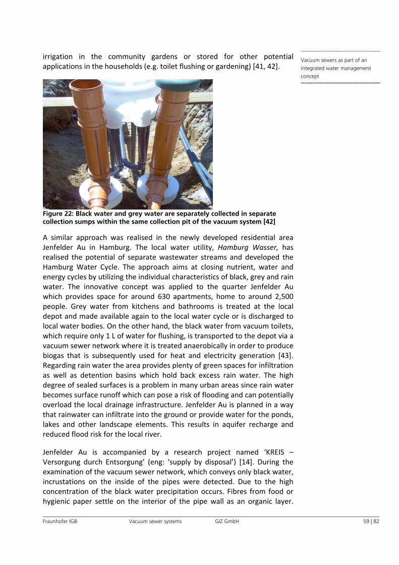
Fraunhofer IGB Vacuum sewer systems GIZ GmbH 59 | 82
Vacuum sewers as part of an
integrated water management
concept
irrigation in the community gardens or stored for other potential applications in the households (e.g. toilet flushing or gardening) [41, 42].
Figure 22: Black water and grey water are separately collected in separate collection sumps within the same collection pit of the vacuum system [42]
A similar approach was realised in the newly developed residential area Jenfelder Au in Hamburg. The local water utility, Hamburg Wasser, has realised the potential of separate wastewater streams and developed the Hamburg Water Cycle. The approach aims at closing nutrient, water and energy cycles by utilizing the individual characteristics of black, grey and rain water. The innovative concept was applied to the quarter Jenfelder Au which provides space for around 630 apartments, home to around 2,500 people. Grey water from kitchens and bathrooms is treated at the local depot and made available again to the local water cycle or is discharged to local water bodies. On the other hand, the black water from vacuum toilets, which require only 1 L of water for flushing, is transported to the depot via a vacuum sewer network where it is treated anaerobically in order to produce biogas that is subsequently used for heat and electricity generation [43]. Regarding rain water the area provides plenty of green spaces for infiltration as well as detention basins which hold back excess rain water. The high degree of sealed surfaces is a problem in many urban areas since rain water becomes surface runoff which can pose a risk of flooding and can potentially overload the local drainage infrastructure. Jenfelder Au is planned in a way that rainwater can infiltrate into the ground or provide water for the ponds, lakes and other landscape elements. This results in aquifer recharge and reduced flood risk for the local river.
Jenfelder Au is accompanied by a research project named ‘KREIS – Versorgung durch Entsorgung’ (eng: ‘supply by disposal’) [14]. During the examination of the vacuum sewer network, which conveys only black water, incrustations on the inside of the pipes were detected. Due to the high concentration of the black water precipitation occurs. Fibres from food or hygienic paper settle on the interior of the pipe wall as an organic layer.
Fraunhofer IGB Vacuum sewer systems GIZ GmbH 60 | 82
Vacuum sewers as part of an
integrated water management
concept
Then urease‐positive bacteria grow on the biofilm and increase the hydrolysis of urea contained in the black water. As a result of the change in pH the chemical solubility of calcium‐phosphate, carbonate compounds and ammonium magnesia phosphate changes and precipitation products form. Crystalline structures with high stability form which provide further breeding ground for bacteria [14]. Factors which contribute to the formation of incrustations include existing incrustations, temperature, leaks and surface roughness. Water hardness also contributes to incrustations but has proven to be a minor factor. The compounds contained in black water have a greater impact. It is also important to consider the flow velocity which is a function of the pipe diameter. If the pipe is too large the transport velocity is reduced which facilitates the formation of incrustations. Measures to prevent or remove incrustations include high pressure flushing and timely maintenance and cleaning activities. Additional access points for servicing need to be provided.
A different challenge arises when vacuum sewers are supposed to service high‐rise buildings. The large flows which can occur in multi‐storey residential buildings can overwhelm individual valves. Thus, it is important to adjust the flow. One approach to tackle this issue is the provision of a buffer tank of sufficient volume. A configuration with multiple valves is also possible. For large buildings several buffer tanks or even several connections can pose a solution to large wastewater volumes. Another approach involves the separation of black water and grey water. Greywater makes up more than 50% of the daily wastewater flows [45]. Compared to black water greywater can be treated much easier as it contains less organic pollutants, nutrients and bacteria. The treatment of grey water in a fluidised bed process can be considered state‐of‐the‐art, as there are plants operating for 10 years in Germany [44].
While the vacuum sewer could be used to transport the black water to the treatment plant grey water could be treated and reused onsite. While this can be challenging to implement in existing multi‐storey buildings newly planned buildings should consider the local treatment and reuse concept. Clarification is needed on the cost compensation for the initial investment costs for additional pipework and the decentralised treatment facility. In Germany, the extra costs for a second pipe network and a modern grey water treatment have been estimated to be around 20 € per m2 living area for new multi‐storey buildings. The area demand for the treatment plant is around 0.1 m2 per inhabitant [44]. This approach could effectively reduce the amount of wastewater and simultaneously reduce the fresh water demand of these buildings. In some countries, such as Vietnam, black and greywater are traditionally collected separately and while black water is often partially treated in onsite septic tanks greywater is commonly discharged into the environment without further treatment [46]. This
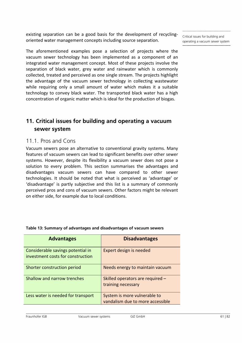
Fraunhofer IGB Vacuum sewer systems GIZ GmbH 61 | 82
Critical issues for building and
operating a vacuum sewer system
existing separation can be a good basis for the development of recycling‐oriented water management concepts including source separation.
The aforementioned examples pose a selection of projects where the vacuum sewer technology has been implemented as a component of an integrated water management concept. Most of these projects involve the separation of black water, grey water and rainwater which is commonly collected, treated and perceived as one single stream. The projects highlight the advantage of the vacuum sewer technology in collecting wastewater while requiring only a small amount of water which makes it a suitable technology to convey black water. The transported black water has a high concentration of organic matter which is ideal for the production of biogas.
11. Critical issues for building and operating a vacuum
sewer system
11.1. Pros and Cons Vacuum sewers pose an alternative to conventional gravity systems. Many features of vacuum sewers can lead to significant benefits over other sewer systems. However, despite its flexibility a vacuum sewer does not pose a solution to every problem. This section summarises the advantages and disadvantages vacuum sewers can have compared to other sewer technologies. It should be noted that what is perceived as ‘advantage’ or ‘disadvantage’ is partly subjective and this list is a summary of commonly perceived pros and cons of vacuum sewers. Other factors might be relevant on either side, for example due to local conditions.
Table 13: Summary of advantages and disadvantages of vacuum sewers
Advantages Disadvantages
Considerable savings potential in investment costs for construction
Expert design is needed
Shorter construction period Needs energy to maintain vacuum
Shallow and narrow trenches Skilled operators are required –training necessary
Less water is needed for transport System is more vulnerable to vandalism due to more accessible
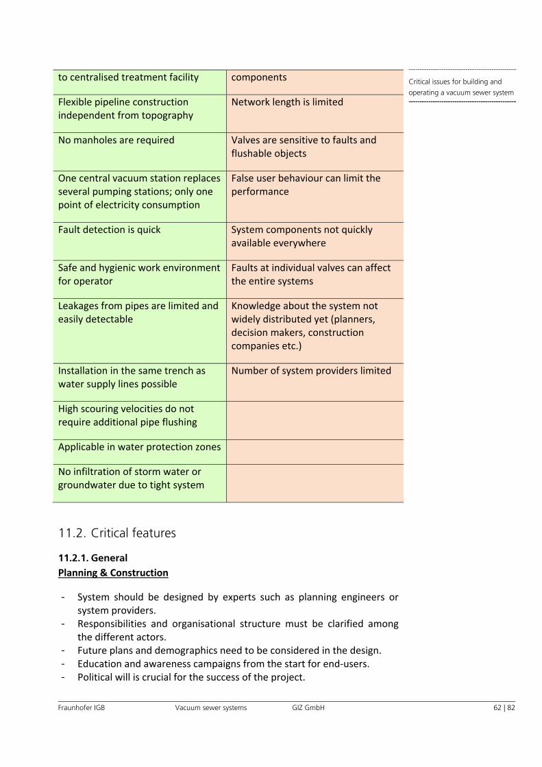
Fraunhofer IGB Vacuum sewer systems GIZ GmbH 62 | 82
Critical issues for building and
operating a vacuum sewer system
to centralised treatment facility components
Flexible pipeline construction independent from topography
Network length is limited
No manholes are required Valves are sensitive to faults and flushable objects
One central vacuum station replaces several pumping stations; only one point of electricity consumption
False user behaviour can limit the performance
Fault detection is quick System components not quickly available everywhere
Safe and hygienic work environment for operator
Faults at individual valves can affect the entire systems
Leakages from pipes are limited and easily detectable
Knowledge about the system not widely distributed yet (planners, decision makers, construction companies etc.)
Installation in the same trench as water supply lines possible
Number of system providers limited
High scouring velocities do not require additional pipe flushing
Applicable in water protection zones
No infiltration of storm water or groundwater due to tight system
11.2. Critical features
11.2.1. General
Planning & Construction
- System should be designed by experts such as planning engineers or system providers.
- Responsibilities and organisational structure must be clarified among the different actors.
- Future plans and demographics need to be considered in the design. - Education and awareness campaigns from the start for end‐users. - Political will is crucial for the success of the project.
Fraunhofer IGB Vacuum sewer systems GIZ GmbH 63 | 82
Critical issues for building and
operating a vacuum sewer system
- Supervision during construction is important. - Selection of reliable and trustworthy contractors. - In case accurate data is unavailable 100‐150 L/person/day and
0.005 L/person/s should be used to estimate the potential wastewater accumulation and flow in the service area; this may vary strongly in different regions of the world.
- Vacuum sewer systems should take into account considerations of future demographic and development trends and thus the system should be designed with sufficient capacity to enable additional connections and extensions in the future.
Operation & maintenance
- Maintain close relationship with manufacturer. - Operational staff should be trained according to the high demand on
technical knowledge; 3‐6 months of training during start‐up phase should be considered in planning and budgeting.
- Maintenance tasks should be carried out according to the planner’s and manufacturer’s recommendations documented in the maintenance plan.
11.2.2. Collection pits
Planning & Construction
- Buffer tanks for connections with continuous large amounts of wastewater or flows above 4 m³/h or population equivalents of more than 20 people to one collection pit.
- Collection chambers evenly distributed along mains – long distances without collection chamber should be avoided.
- Large flows should occur closer to the vacuum station, not at the end of the network.
- Gravity line from house to collection pit should be laid at a slope of 1:60 or steeper
- Minimum pipe diameter should be 100 mm (PVC or PE). - Sump volume should consider space for back logs; total holding volume
should be 25% of the expected daily flow (holding volume can include volume form gravity line from house connection)
- Measures to prevent infiltration of storm water or runoff (e.g. lids …). - Material selection according to expected load (e.g. traffic …). - Corrosion proof material to withstand any forces likely to work on the
material; inside smooth to allow self‐cleaning. - Sufficient air supply in the pit or at the valve – external breathers if
necessary. - Install check‐valves for house‐to‐pit connection. - Valve pit must be made explosion proof. - Monitoring of valve pit is advisable – battery powered designs are
available.
Fraunhofer IGB Vacuum sewer systems GIZ GmbH 64 | 82
Critical issues for building and
operating a vacuum sewer system
- Limit the number of houses connected to a valve pit (maximum 4). - Accepting flow from other systems such as gravity systems is to be
avoided.
Operation & maintenance
- Air – liquid ratio should be adjusted at the vacuum valve as needed; lower ratios represent higher efficiency but operational experience has shown that L/A ratio varies between 3:1 – 15:1 depending on where the valve is located in the network.
- Cycle volume is 35 – 60 L. - Provide for backup electricity. - Conduction of visual inspection according to maintenance plan. - Repair of faulty, blocked or broken pipes inside the pit.
11.2.3. Interface valve
Planning & Construction
‐ All components that come into contact with wastewater (e.g. sensor
pipe) must be resistant to wear.
‐ In case of large flows, buffer tanks or multiple valve setups should be
considered.
‐ Valve size should be selected according to expected flow; 3 inch (~7.6
cm) valves are commonly used.
‐ Remote monitoring system at the valve pit is recommended.
Operation & maintenance
‐ Monitoring of pumps to determine any leaks and control costs. ‐ Maintenance of components should be carried out according to
developed maintenance plan and manufacturer recommendations. ‐ The valve needs to remain open for the duration of one batch
evacuation, including sufficient time to draw in air; opening time can be adjusted at the valve.
‐ Air /liquid ratio should be adjusted as needed according to efficiency and economic aspects; the ratio should fall between 3:1 and 15:1.
‐ Sufficient spare parts and units should be available to the operator. ‐ The opening mechanism should be adjusted so that the valve only
opens if local pressure conditions are below ‐ 0.15 bar. - If the bottom of the chamber is deeper than 1 m below the valve the
threshold for the opening mechanism must be adjusted to lower pressures (< ‐ 0.35 bar).
11.2.4. Vacuum lines / network
Planning & Construction
Fraunhofer IGB Vacuum sewer systems GIZ GmbH 65 | 82
Critical issues for building and
operating a vacuum sewer system
‐ The largest pipe must lead to the vacuum station; smaller pipes divert from the larger pipes (hierarchy of diameters).
‐ It is recommended that the system provider instructs the staff of the construction company regarding the construction of the network.
‐ Division valves should separate different service areas for operational flexibility.
‐ Total hydraulic lift should not exceed 6 m. ‐ Pipes should be laid with a slope of at least 0.2 % (1:500). ‐ Minimum distance between two lifts should be 6 m. ‐ Maximum lift height should not exceed 0.9 m. ‐ Lifts should be realised using two 45° fittings joined by a piece of pipe. ‐ Head losses and friction losses must be considered during design as
they govern the maximum length of the network. ‐ Pipe material should be resistant to chemical and biochemical
influences that can result in corrosion as well as resistant to mechanical wear and temperatures up to 35°C (or higher, depending on the local conditions).
‐ Pipes, fittings and gaskets need to meet the requirements to operate under the given pressure environment.
‐ Joining the collection chamber to the service line should take place at the upper part of the service line at an angle of around 60° to the vertical axis and 55° to the direction of flow.
‐ Joining the service line to a vacuum main should be done at an angle of 45° to the direction of flow.
‐ Minimum distance between two joining pipes and a lift should be 2m. ‐ The depths in which the pipes are laid should consider seasonal changes
in groundwater table, frost and other local conditions. ‐ Pipes should be embedded in sand and covered by a liner, a layer of
gravel and the trench material. ‐ Division valves should be placed in intervals of maximum 450 m along
the vacuum main and for the separation of lateral lines which are longer than 200 m.
‐ Gauge taps (inspection pipes) need to provide for the insertion of manometers, and plugs should be placed every 100 m and before as well as behind division valves.
‐ Division and inspection valves need to be indicated.
Operation & maintenance
‐ When black water is transported separately, additional cleaning of pipes is required.
‐ Vacuum conditions should be inspected regularly at inspection valves. ‐ Locations of division and inspection valves should be documented. ‐ Division valves should be used to carry out maintenance activities.
11.2.5. Vacuum station
Planning & Construction
Fraunhofer IGB Vacuum sewer systems GIZ GmbH 66 | 82
Critical issues for building and
operating a vacuum sewer system
‐ The location of the station should be selected carefully, ideally at the lowest point of the service area.
‐ Noise and odour disturbances for residents can emerge and preventive measures need to be provided.
‐ A biofilter with sufficient capacity should be installed. ‐ The vacuum station should be protected from vandalism. ‐ Measures for insulation, ventilation and heating should be provided at
the station. ‐ The number of vacuum pumps should be selected so that normal
operation can be ensured while one pump is offline. ‐ If multiple vacuum tanks are constructed the incoming mains should be
equipped with cross connections and division valves. ‐ The vacuum tank needs to be equipped with appropriate sensors in
order to trigger the relevant processes (e.g. pump activity) and alarms (e.g. low vacuum).
‐ Vacuum tanks placed underground do not have to overcome additional height and thus more head is available for transport.
‐ Access to the tank and its interior needs to be ensured for maintenance and cleaning.
‐ The number of sewerage pumps should be selected so that normal operation can be ensured while one pump is offline.
‐ The diameter of the inlet of the sewerage pumps should be at least as large as the diameter of the vacuum main.
‐ If the inlet is smaller than the vacuum main a shredding device should be installed to shred large objects.
‐ Wastewater pumps placed inside the vacuum tank need to be certified to operate under vacuum pressure conditions.
‐ An alarm system needs to be installed which notifies the operator in case of alarms (e.g. via text message).
‐ A backup electricity supply needs to be provided in case of power blackout.
‐ The development of a maintenance manual and schedule according to the manufacturer’s and planner’s recommendations is imperative.
Operation & maintenance
‐ Vacuum pumps should maintain an operating pressure between ‐0.5 and ‐0.7 bar
‐ Minimum recommended vacuum pump capacity is 4.3 m³/min. ‐ Vacuum pumps should not run continuously, but should be able to in
order to continue operation in special events. ‐ Vacuum pumps should be maintained according to the manufacturer’s
instructions. ‐ The biofilter material needs to be exchanged every 3‐5 years. ‐ An adequate alarm system needs to be maintained.
Fraunhofer IGB Vacuum sewer systems GIZ GmbH 67 | 82
Summary & conclusion ‐ Appropriate maintenance of components according to the developed
plan is crucial. ‐ Record keeping on data, tasks and inventory must be done thoroughly.
12. Summary & conclusion Vacuum sewers are considered an alternative wastewater collection system and whether it is the technology of choice depends on a multitude of criteria and service area conditions. The presented chapters aim at providing adequate information to decision makers and other actors involved in wastewater service provision in order to make an informed decision on whether vacuum sewers pose a viable option to a certain service area.
Technical improvements, increased operational experience and the paradigm change towards integrated water management have led to increased interest in vacuum sewers in the past decades. This guide presents the relevant aspects regarding the concept, planning and operation of vacuum sewer systems. The strengths and weaknesses of the technology are highlighted, including rough cost estimates for individual components and the operation and maintenance of vacuums sewers. Applicability, investment and operational costs can vary significantly between regions and need to be assessed under local conditions. Nevertheless a certain savings potential over other sewer systems exists for vacuum sewers. The potential use of vacuum sewers as transport technology within integrated water management concepts is shown.
In summary it can be said that all stages from planning and design to O&M require expert technical knowledge to ensure the sustainability of a vacuum sewer project. Vacuum sewers compose of many mechanical parts predominantly in form of the interface valves and pump equipment at the vacuum station which can experience faults from false user behaviour and inadequate maintenance. The absence of this expertise and clear organisational structures can lead to severe and finally to irreparable damages, eliminating the potential benefits vacuum sewers can have over other forms of sewerage conveyance. Therefore, it is not surprising that until now the majority of vacuum sewer projects have been realised in Europe, the USA, Australia and Japan where market actors and knowledge associated with the vacuum technology are well distributed.
The major benefit of the vacuum sewer technology is the pipe network. The greatest cost savings are achieved here through shallow trenches, smaller pipe diameters and high layout flexibility. Additionally, the environmental benefits are significant. Leakage is very rare making the vacuum sewer technology more suitable for areas where other sewerage systems need to
Fraunhofer IGB Vacuum sewer systems GIZ GmbH 68 | 82
Summary & conclusion take extra precautions, such as in environmentally sensitive areas and water protection zones.
However, in the face of increasing efforts to tackle water related issues, including the provision of sanitary services, while incorporating aspects of environmental, social and economic sustainability the vacuum sewer technology should be considered as a possible option for future wastewater infrastructure projects.
Fraunhofer IGB Vacuum sewer systems GIZ GmbH 69 | 82
Summary & conclusion References1. Schluff R Entwässerungstechnik im Umbruch: Bemessung und Konstruktion der
Unterdruckentwässerung. In: Stuttgarter Berichte zur Siedlungswasserwirtschaft
1996, vol 140
2. Miles SW Alternative Wastewater Collcetion Systms Manual: WEF Press; New York
: McGraw-Hill; Water Environment Federation;2010, 6th edn.
3. DWA Besondere Entwässerungsverfahren: Teil 1:
Unterdruckentwässerungssysteme außerhalb von Gebäuden; 2008; Bieber,
Helmut; Dippold, Walter; Deutsche Vereinigung für Wasserwirtschaft, Abwasser
und Abfall e.VEckstädt, Hartmut; Flick, Karl-Heinz; Howe, Harald; Jedlitschka,
Jens; Kleinschroth, Adolf; Klippel, Angela; Petersohn, Thomas; Roediger, Markus;,
Hennef
4. Naret R (2007) Vacuum Sewers - Design and Installation Guidelines: Course No C-
8015. http://www.airvac.com/pdf/Vacuum_Sewers_Design_Installation.pdf.
Accessed 15. December, 2016
5. Naret R (2008) Vacuum sewers 101. www.airvac.com/pdf/Vacuum Sewers
101.pdf
6. Islam MS (2016) Comparative evaluation of vacuum sewer and gravity sewer
systems. Int J Syst Assur Eng Manag. doi: 10.1007/s13198-016-0518-z
7. Sustainable Sanitation and Water Management (2012) Sewer Systems
(Powerpoint); http://www.sswm.info/content/vacuum-sewers; Accessed :
28.11.2016
8. Mäkinen M (2015) Operation of vacuum sewer system - case Ondangwa,
Namibia: Master of Science Thesis; Tampere University of Technology;
https://dspace.cc.tut.fi/dpub/handle/123456789/24063?show=full;
Accessed: 15.December, 2016
9. DIN Deutsches Institut für Normung (1997) Unterdruckentwässerungssysteme
außerhalb von Gebäuden; DIN EN 1091; Beuth
10. Little CJ (2004) A comparison of sewer reticulation system design standards
gravity, vacuum and small bore sewers: Proceedings of the 2004 Water Institute
of Southern Africa (WISA) Biennial Conference
11. Günthert FW, Cvaci D (2005) Vergleich von verschiedenen
Entwässerungssystemen; Siedlungswasserwirtschaft und Abfalltechnik; Universität
der Bundeswehr München
12. Buchanan J, Deal N, Lindbo D et al. (2010) Fact Sheet C4: Vacuum Sewer
Systems; Water Environment Research Foundation;
http://www.werf.org/i/c/DecentralizedCost/Decentralized_Cost.aspx; accessed: 15.
December, 2016
13. U.S. Environmental Protection Agency (1991) Manual: Alternative Wastewater
Collection Systems;
https://ntrl.ntis.gov/NTRL/dashboard/searchResults/titleDetail/PB93116259.xhtml;
accessed: 15.December, 2016
14. Giese T, Londong J (2015) Kopplung von regenerativer Energiegewinnung mit
innovativer Stadtentwässerung; Synthesebericht zum Forschungsprojekt KREIS;
Rhombos; Bauhaus-Universität Weimar
15. Water Environment Federation (2008) Alternative Sewer Systems FD-12: WEF
Manual of Practice, 2nd edn. McGraw-Hill Professional
Fraunhofer IGB Vacuum sewer systems GIZ GmbH 70 | 82
Summary & conclusion 16. IWR - Ingenieurbüro für Wasserwirtschaft und Ressourcenmanagement (2016)
Investment costs for vacuum sewers; personal communication
17. Elawwad A, Ragab M, Abdel-Halim H (2014) Vacuum sewerage system in
developing regions and the impact on environemtnal management; Proceedings
of the 4th International Conference on Environmental Pollution and Remediation
18. Masteller & Moler I (2013) Sanitary Sewer Feasibility Study and Report for the
North Sebastian Area; Indian River County, Florida
19. Beauclair R (2010) Development and Disappointment: an Ethnographic Study of
Kosovo Informal Settlement's Water and Sanitation System Upgrade; Department
of Social Anthropology; M.A. dissertation, University of Cape Town
20. Vakuum Anlagen Bau - Herr Mathias (2016) Kenndaten zur Vakuumkanalisation;
personal communication
21. Freistaat Sachsen - Staatsministerium für Umwelt und Landwirtschaft (2004)
Abwasserinvestitionen im ländlichen Raum: Entscheidungsfindung am Beispiel des
Ortsteils Putzkau der Gemeinde Schmölln-Putzkau
22. Naret R (2009) Vacuum Sewers – Operation and Maintenance and System
Management Guidelines: Course Number C-4029. www.airvac.com/pdf/Vacuum
O&M and System Management.pdf. Accessed 15.December, 2016
23. Miszta-Kruk K (2016) Reliability and failure rate analysis of pressure, vacuum and
gravity sewer systems based on operating data. Engineering Failure Analysis
61: 37–45. doi: 10.1016/j.engfailanal.2015.07.034
24. Królikowska J, Debowska B, Królikowski A (2013) An evaluation of potential
losses associated with the loss of vacuum sewerage system reliability.
Environmental Engineering IV: 51–57. doi: 10.1201/b14894-9
25. Terryn IC, Lazar G (2016) Driving forces affecting the adoption of Eco-innovation:
A survey on vacuum sewer systems. Environmental Engineering and Management
Journal 15 (3): 589–598
26. Gemeinde Ernsgarden Kanalsystem soll weiter optimiert werden.
http://www.ernsgaden.de/index.php?id=9760,604. Accessed 16 Nov 2016
27. Gemeinde Magazin Ernsgaden (2016) Vakuumkanal oder Druckkanal?
Kanalsystem soll weiter optimiert werden;
http://www.ernsgaden.de/index.php?id=9760,604; accessed: 15. December
2016(1)
28. Taing L, Armitage NP, Spiegel A (2011) Cape Town's problematic vacuum sewer:
A reflection on the technical, social and institutional blockages that constrain
municipal management; 12th International Conference on Urban Drainage, Porto
Alegre/ Brazil
29. FLOVAC Kawakawa Bay New Zealand: Septic Tank Replacement;
http://flovac.com/wp-content/uploads/2014/02/Kawakawa-Bay-NZ.pdf; accessed:
15. December 2016
30. Watercare Top environmental award for Kawakawa Bay wastewater system.
http://www.watercare.co.nz/about-watercare/news/Pages/Top-environmental-
award-for-Kawakawa-Bay-wastewater-system.aspx. Accessed 30. November,2016
31. SCRIT (2014) Building a stronger wastewater network: Vacuum wastewater
system; Stronger Christchurch Infrastructure Rebuild Team;
http://strongerchristchurch.govt.nz/sites/strongerchristchurch.govt.nz/files/u29/14
0612%20Vacuum%20information%20sheet%20FINAL.pdf; accessed:
15.December 2016
Fraunhofer IGB Vacuum sewer systems GIZ GmbH 71 | 82
Summary & conclusion 32. Bayer M, Kopfhammer N (2012) Kanalisierung mittels Vakuumentwässerung;
Roediger Vacuum; BilfingerBerger Facility Services; presentation
33. IWR - Ingenieurbüro für Wasserwirtschaft und Ressourcenmanagement (2012)
Vacuum projects from the view of an operator: Germany, Hesse, Schwalmtal -
Rainrod; presentation
34. Kamble SG, Kumthekar MB, Koli DH (2015) Vacuum sewer system. International
Journal for Scientific Research & Development(3)
35. Kjerstadius H, Haghighatafshar S, Davidsson A (2015) Potential for nutrient
recovery and biogas production from blackwater, food waste and greywater in
urban source control systems. Environ Technol 36(13-16): 1707–1720. doi:
10.1080/09593330.2015.1007089
36. Bilfinger Water Technologies GmbH (2015) Eco Settlement Outapi / Namibia
Reference Sheet
37. Zimmermann M, Deffner J, Müller K et al. (2015) CUVE waters - Sanitation and
Water Reuse Implementation Concept
38. www.deus21.de DEUS 21: DEcentralised Urban infrastructure Systems.
www.deus21.de. Accessed 16 Nov 2016
39. Oldenburg M Die ökologische Wohnsiedlung Flintenbreite, Lübeck;
http://www.woche-der-umwelt.de/media/31050611220875b1.pdf; accessed: 15.
December, 2016
40. Oldenburg M, Albold A, Otterpohl R (2008) Vacuum Sewerage and Greywater
treatment: Experience of 8 years of operation, Oldenburg
41. www.ecoquartier.de ecoQuartier Pfaffenhofen/ Ilm. http://www.ecoquartier.de/.
Accessed 23 Nov 2016
42. Aqseptence Group GmbH (2012) Vakuumkanalisation für ökologisches
Siedlungskonzept: Projekt Report
43. Freie und Hansestadt Hamburg (2014) Jenfelder Au - Newsletter Juli 2014:
Neugikeiten aus dem neuen Viertel; http://www.jenfelderau-
info.de/index.php/Newsletter.html; accessed; 15. December 2016
44. Gehrke I, Katayama V, Bertling R et al. (2016) ROOF WATER-FARM: Neue
Konzepte für die Siedlungswasserwirtschaft zur urbanen
Nahrungsmittelproduktion. Korrespondenz Abwasser, Abfall(63): 999–1005
45. Mehlhart G Grauwasser weiter auf dem Vormarsch (Greywater on the advance).
fbr-wasserspiegel 2001: 14–16
46. Pham NB, Kuyama T (2013) Urban Domestic Wastewater Management in
Vietnam: Challenges and Opportunities.
https://www.google.com/url?q=https://pub.iges.or.jp/ja/pub/urban-domestic-
wastewater-management-vietnam-
%25E2%2580%2593&sa=U&ved=0ahUKEwiO1P_-
5svRAhVDYJoKHd94DV0QFggEMAA&client=internal-uds-
cse&usg=AFQjCNGjSmRTvZYfv4S3-uUl3JqYRMMMXw. Accessed 18. January,
2017

Fraunhofer IGB Vacuum sewer systems GIZ GmbH 72 | 82
Summary & conclusion
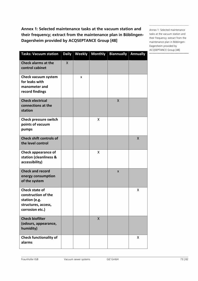
Fraunhofer IGB Vacuum sewer systems GIZ GmbH 73 | 82
Annex 1: Selected maintenance
tasks at the vacuum station and
their frequency; extract from the
maintenance plan in Böblingen-
Dagersheim provided by
ACQSEPTANCE Group [48]
Annex 1: Selected maintenance tasks at the vacuum station and
their frequency; extract from the maintenance plan in Böblingen-
Dagersheim provided by ACQSEPTANCE Group [48]
Tasks: Vacuum station Daily Weekly Monthly Biannually Annually
Check alarms at the control cabinet
X
Check vacuum system for leaks with manometer and record findings
x
Check electrical connections at the station
X
Check pressure switch points of vacuum pumps
X
Check shift controls of the level control
X
Check appearance of station (cleanliness & accessibility)
X
Check and record energy consumption of the system
x
Check state of construction of the station (e.g. structures, access, corrosion etc.)
X
Check biofilter (odours, appearance, humidity)
X
Check functionality of alarms
X
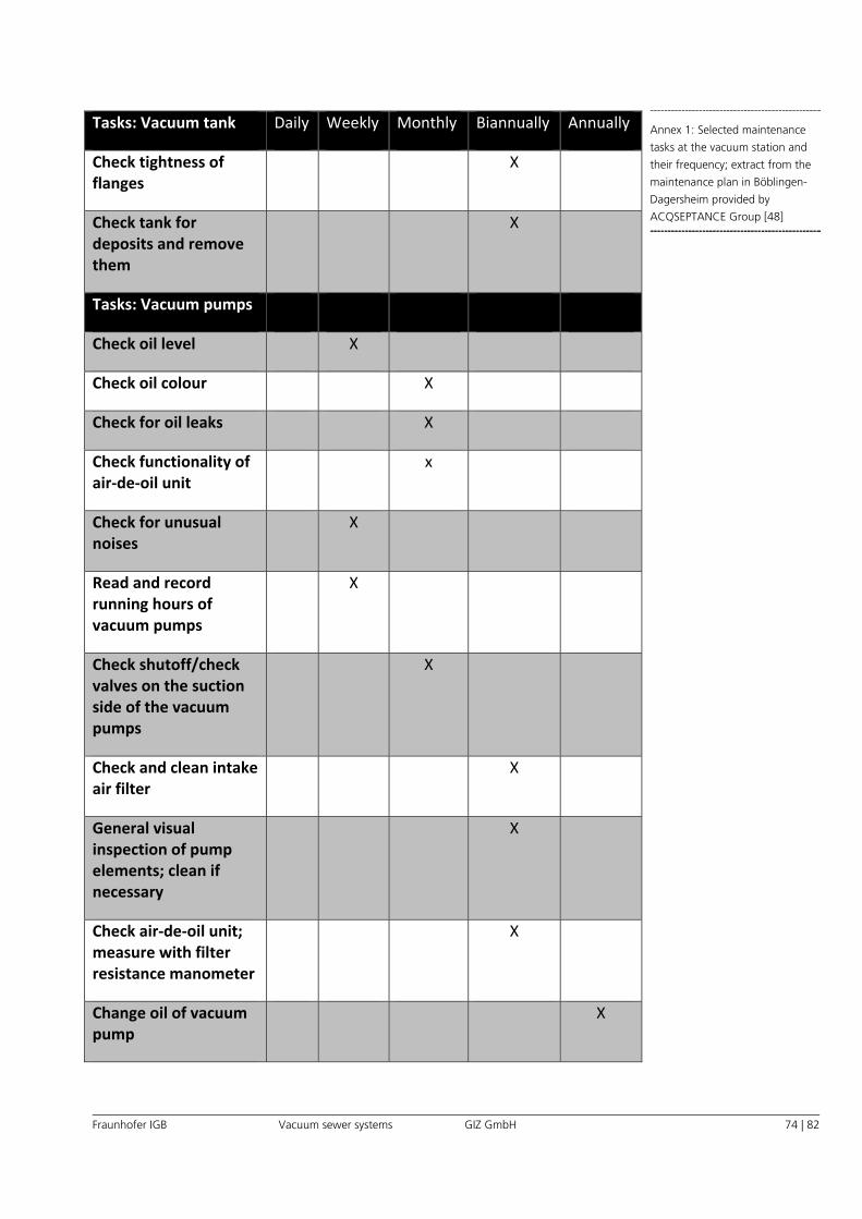
Fraunhofer IGB Vacuum sewer systems GIZ GmbH 74 | 82
Annex 1: Selected maintenance
tasks at the vacuum station and
their frequency; extract from the
maintenance plan in Böblingen-
Dagersheim provided by
ACQSEPTANCE Group [48]
Tasks: Vacuum tank Daily Weekly Monthly Biannually Annually
Check tightness of flanges
X
Check tank for deposits and remove them
X
Tasks: Vacuum pumps
Check oil level X
Check oil colour X
Check for oil leaks X
Check functionality of air‐de‐oil unit
x
Check for unusual noises
X
Read and record running hours of vacuum pumps
X
Check shutoff/check valves on the suction side of the vacuum pumps
X
Check and clean intake air filter
X
General visual inspection of pump elements; clean if necessary
X
Check air‐de‐oil unit; measure with filter resistance manometer
X
Change oil of vacuum pump
X
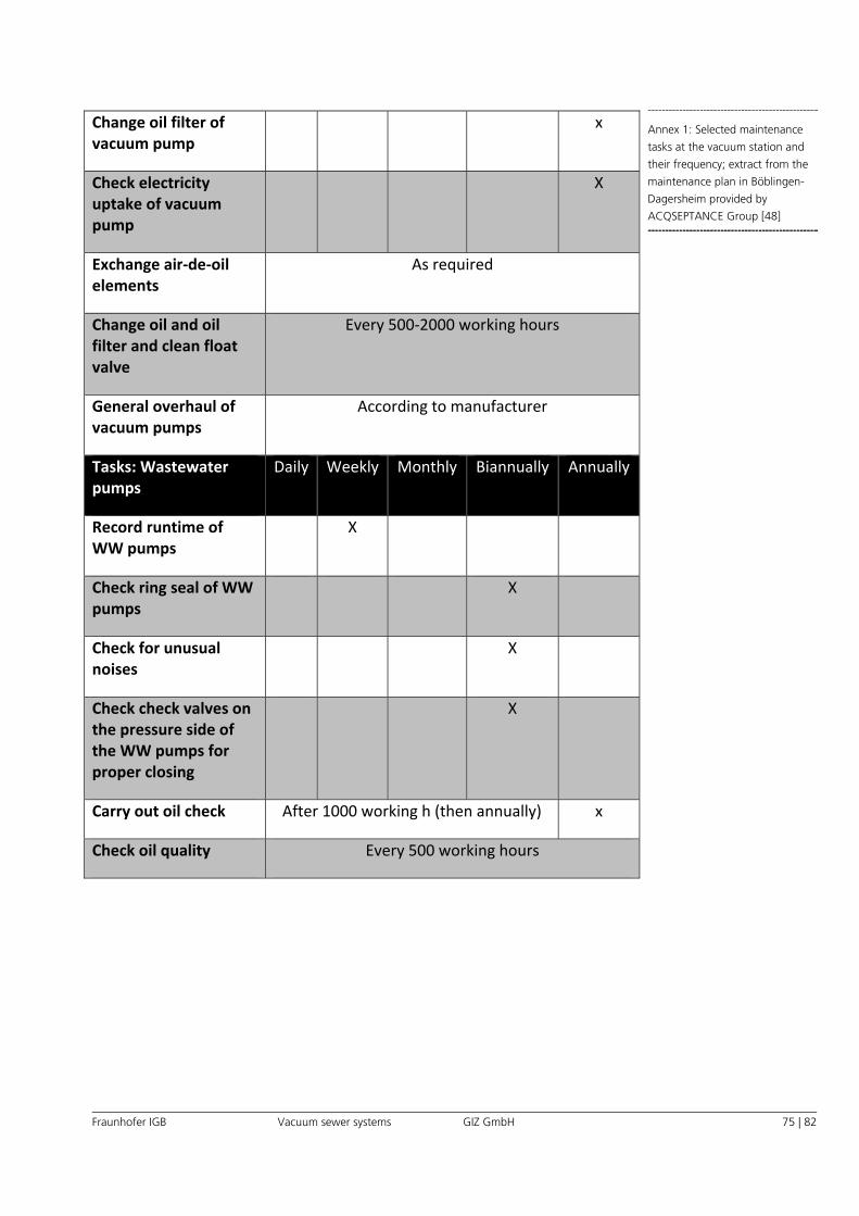
Fraunhofer IGB Vacuum sewer systems GIZ GmbH 75 | 82
Annex 1: Selected maintenance
tasks at the vacuum station and
their frequency; extract from the
maintenance plan in Böblingen-
Dagersheim provided by
ACQSEPTANCE Group [48]
Change oil filter of vacuum pump
x
Check electricity uptake of vacuum pump
X
Exchange air‐de‐oil elements
As required
Change oil and oil filter and clean float valve
Every 500‐2000 working hours
General overhaul of vacuum pumps
According to manufacturer
Tasks: Wastewater pumps
Daily Weekly Monthly Biannually Annually
Record runtime of WW pumps
X
Check ring seal of WW pumps
X
Check for unusual noises
X
Check check valves on the pressure side of the WW pumps for proper closing
X
Carry out oil check After 1000 working h (then annually) x
Check oil quality Every 500 working hours
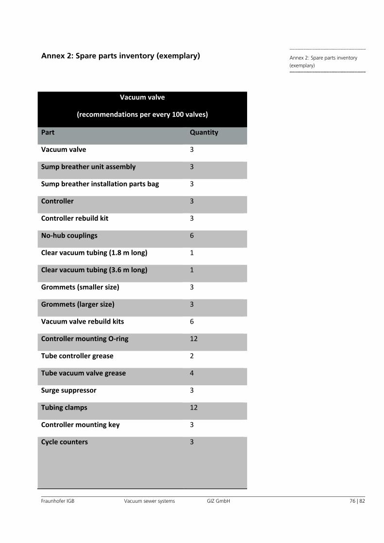
Fraunhofer IGB Vacuum sewer systems GIZ GmbH 76 | 82
Annex 2: Spare parts inventory
(exemplary)
Annex 2: Spare parts inventory (exemplary)
Vacuum valve
(recommendations per every 100 valves)
Part Quantity
Vacuum valve 3
Sump breather unit assembly 3
Sump breather installation parts bag 3
Controller 3
Controller rebuild kit 3
No‐hub couplings 6
Clear vacuum tubing (1.8 m long) 1
Clear vacuum tubing (3.6 m long) 1
Grommets (smaller size) 3
Grommets (larger size) 3
Vacuum valve rebuild kits 6
Controller mounting O‐ring 12
Tube controller grease 2
Tube vacuum valve grease 4
Surge suppressor 3
Tubing clamps 12
Controller mounting key 3
Cycle counters
3
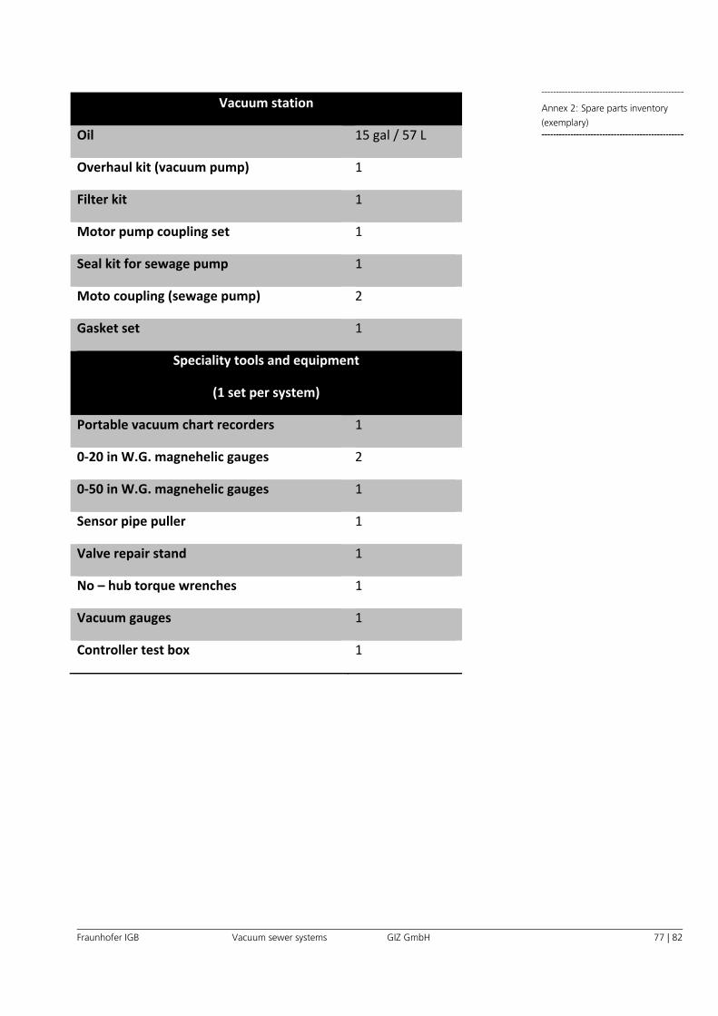
Fraunhofer IGB Vacuum sewer systems GIZ GmbH 77 | 82
Annex 2: Spare parts inventory
(exemplary)
Vacuum station
Oil 15 gal / 57 L
Overhaul kit (vacuum pump) 1
Filter kit 1
Motor pump coupling set 1
Seal kit for sewage pump 1
Moto coupling (sewage pump) 2
Gasket set 1
Speciality tools and equipment
(1 set per system)
Portable vacuum chart recorders 1
0‐20 in W.G. magnehelic gauges 2
0‐50 in W.G. magnehelic gauges 1
Sensor pipe puller 1
Valve repair stand 1
No – hub torque wrenches 1
Vacuum gauges 1
Controller test box 1
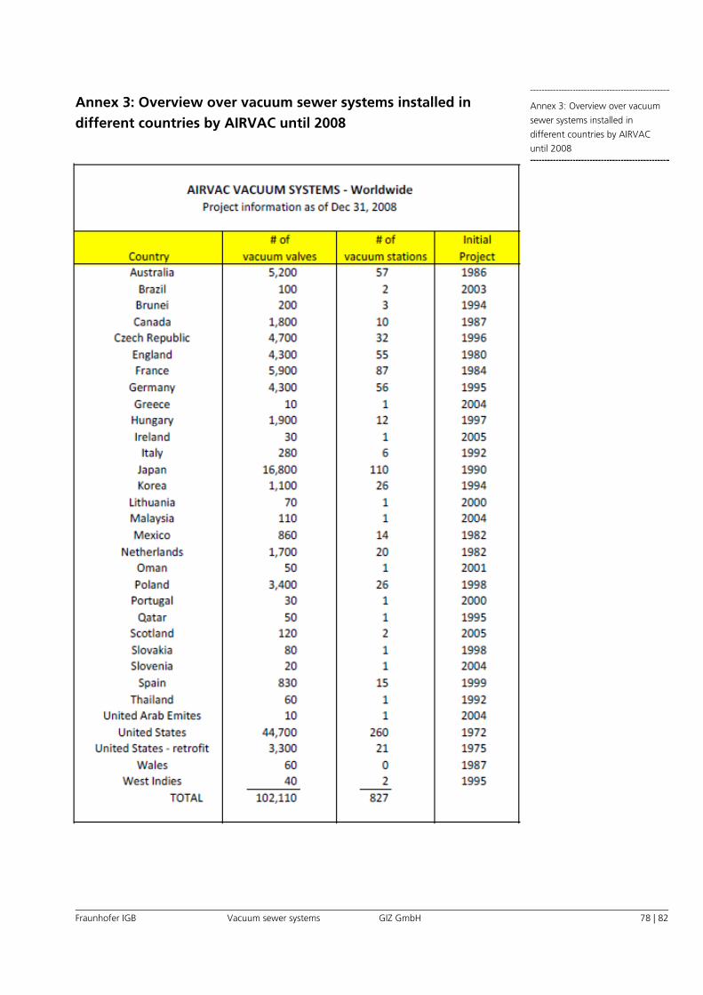
Fraunhofer IGB Vacuum sewer systems GIZ GmbH 78 | 82
Annex 3: Overview over vacuum
sewer systems installed in
different countries by AIRVAC
until 2008
Annex 3: Overview over vacuum sewer systems installed in
different countries by AIRVAC until 2008
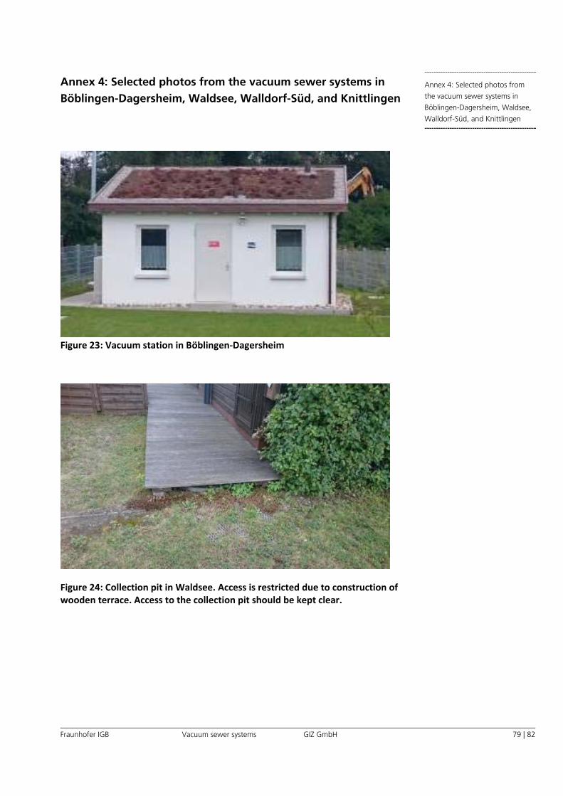
Fraunhofer IGB Vacuum sewer systems GIZ GmbH 79 | 82
Annex 4: Selected photos from
the vacuum sewer systems in
Böblingen-Dagersheim, Waldsee,
Walldorf-Süd, and Knittlingen
Annex 4: Selected photos from the vacuum sewer systems in
Böblingen-Dagersheim, Waldsee, Walldorf-Süd, and Knittlingen
Figure 23: Vacuum station in Böblingen‐Dagersheim
Figure 24: Collection pit in Waldsee. Access is restricted due to construction of wooden terrace. Access to the collection pit should be kept clear.
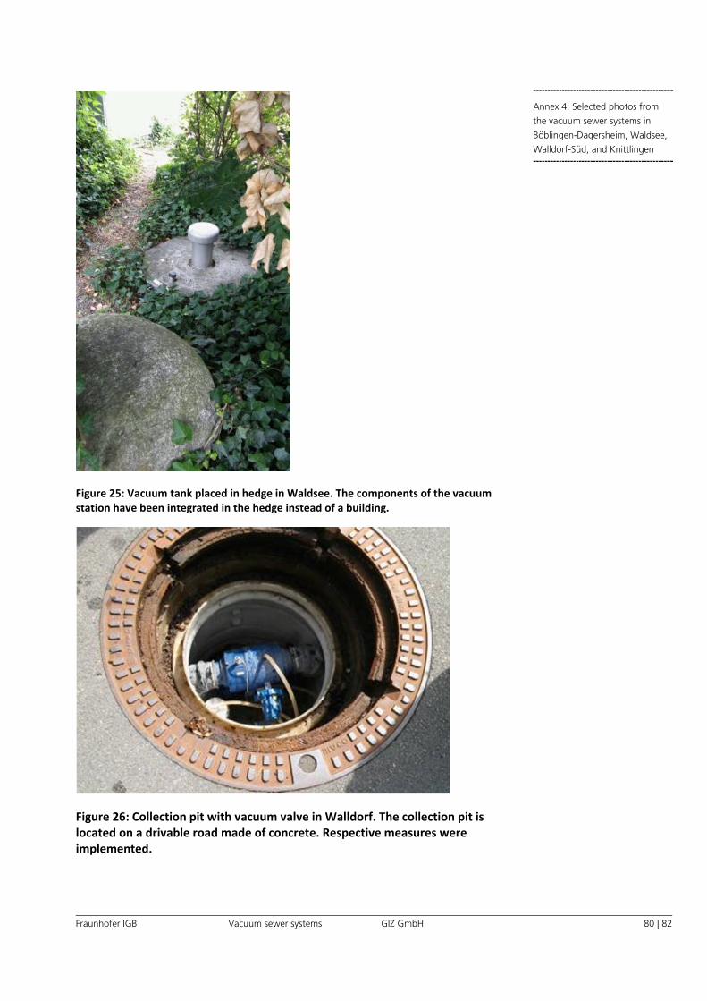
Fraunhofer IGB Vacuum sewer systems GIZ GmbH 80 | 82
Annex 4: Selected photos from
the vacuum sewer systems in
Böblingen-Dagersheim, Waldsee,
Walldorf-Süd, and Knittlingen
Figure 25: Vacuum tank placed in hedge in Waldsee. The components of the vacuum station have been integrated in the hedge instead of a building.
Figure 26: Collection pit with vacuum valve in Walldorf. The collection pit is located on a drivable road made of concrete. Respective measures were implemented.
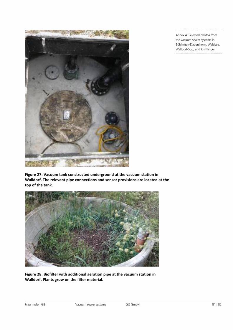
Fraunhofer IGB Vacuum sewer systems GIZ GmbH 81 | 82
Annex 4: Selected photos from
the vacuum sewer systems in
Böblingen-Dagersheim, Waldsee,
Walldorf-Süd, and Knittlingen
Figure 27: Vacuum tank constructed underground at the vacuum station in Walldorf. The relevant pipe connections and sensor provisions are located at the top of the tank.
Figure 28: Biofilter with additional aeration pipe at the vacuum station in Walldorf. Plants grow on the filter material.
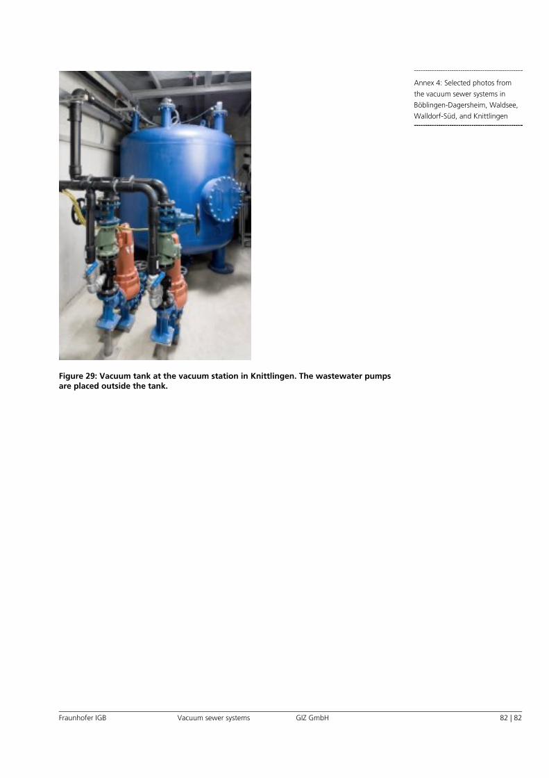
Fraunhofer IGB Vacuum sewer systems GIZ GmbH 82 | 82
Annex 4: Selected photos from
the vacuum sewer systems in
Böblingen-Dagersheim, Waldsee,
Walldorf-Süd, and Knittlingen
Figure 29: Vacuum tank at the vacuum station in Knittlingen. The wastewater pumps are placed outside the tank.