Embed Size (px)
Citation preview
Gasdruckregelgerät typ VR75
Pressure Regulator Type VR 75
Betriebsanleitung Instruction Manual

2
Inhaltsverzeichnis / Contents Seite/Page
DECE konformitätserklärung . . . . . . . . . . . . . . . . . . . . . . . . . . . . . . . . . . . . . . . . . . . . . . . . . . . . . . . . . . . . . . . . . 4
Aufgabe, Afbau, Funktion . . . . . . . . . . . . . . . . . . . . . . . . . . . . . . . . . . . . . . . . . . . . . . . . . . . . . . . . . . . . . . . . 5
Typenübersicht . . . . . . . . . . . . . . . . . . . . . . . . . . . . . . . . . . . . . . . . . . . . . . . . . . . . . . . . . . . . . . . . . . . . . . . . . . 6
Einbau, Inbetriebnahme, Federwechsel . . . . . . . . . . . . . . . . . . . . . . . . . . . . . . . . . . . . . . . . . . . . . . . . . . . . . 8
Wartung, Anschlüsse und Abmessungen . . . . . . . . . . . . . . . . . . . . . . . . . . . . . . . . . . . . . . . . . . . . . . . . . . . 9
GBCE Declaration of Conformity . . . . . . . . . . . . . . . . . . . . . . . . . . . . . . . . . . . . . . . . . . . . . . . . . . . . . . . . . . . . . 10
Task, Structure . . . . . . . . . . . . . . . . . . . . . . . . . . . . . . . . . . . . . . . . . . . . . . . . . . . . . . . . . . . . . . . . . . . . . . . . . 11
Function, Type Overview . . . . . . . . . . . . . . . . . . . . . . . . . . . . . . . . . . . . . . . . . . . . . . . . . . . . . . . . . . . . . . . . . 12
Installation, Commissioning, Spring change . . . . . . . . . . . . . . . . . . . . . . . . . . . . . . . . . . . . . . . . . . . . . . . . . 14
Maintenance, Connection and Dimensions . . . . . . . . . . . . . . . . . . . . . . . . . . . . . . . . . . . . . . . . . . . . . . . . . 15
3
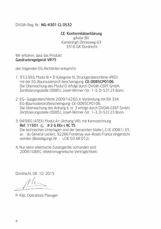
DVGW-Reg . Nr .: NG-4301 CL 0532
CE KonformitätserklärunggAvilar BV
Kamerlingh Onnesweg 63 3316 GK Dordrecht
Wir erklären, dass das Produkt Gasdruckregelgerät VR75
den folgenden EG-Richtlinien entspricht:
1 . 97/23/EG Modul B + D Kategorie IV; Druckgeräterichtlinie (PED) mit der EG-Baumusterprüf-bescheinigung: CE-0085CP0106 . Die Überwachung des Modul D erfolgt durch DVGW-CERT GmbH, Zertifizierungsstelle (0085); Josef-Wirmer-Str . 1-3, D-53123 Bonn .
2 . EG- Gasgeräterichtlinie 2009/142/EG in Verbindung mit EN 334 EG-Baumusterprüfbescheinigung: CE-0085CP0106 . Die Überwachung des Anhang II, nr . 3 erfolgt durch DVGW-CERT GmbH, Zertifizierungsstelle (0085); Josef-Wirmer-Str . 1-3, D-53123 Bonn .
3 . 94/9/EG (ATEX) Modul A+ (Anhang VIII), mit Kennzeichnung Ref. 11501 II 2 G EEx c IIC T5 Die technischen Unterlagen sind der benannten Stelle L .C .I .E (0081) 33, av . du Général Leclerc, 92266 Fontenay-aux-Roses France eingereicht worden (Bestätigungs Nr .: LCIE 03 AR 012) .
4 . Nur wenn elektrische Zusatzgeräte vorhanden sind: 2004/108/EC (elektromagnetische Verträglichkeit)
Dordrecht, 06 .10 .2015
P . Klijs, Operations Manager
4
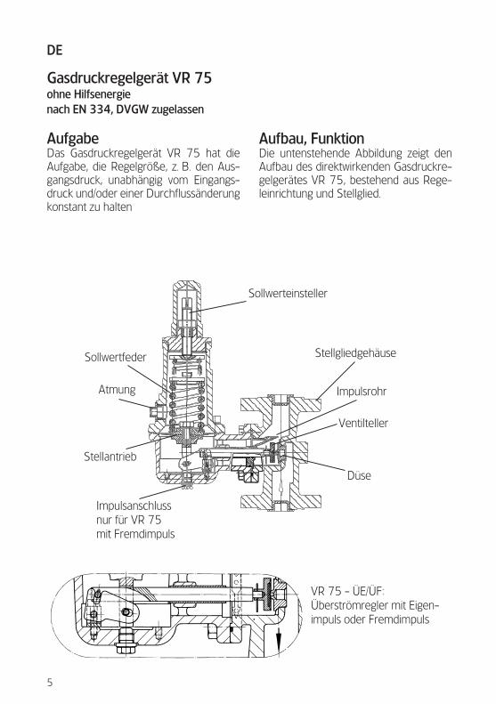
Gasdruckregelgerät VR 75ohne Hilfsenergienach EN 334, DVGW zugelassen
AufgabeDas Gasdruckregelgerät VR 75 hat die Aufgabe, die Regelgröße, z . B . den Aus-gangsdruck, unabhängig vom Eingangs-druck und/oder einer Durchflussänderung konstant zu halten
Aufbau, FunktionDie untenstehende Abbildung zeigt den Aufbau des direktwirkenden Gasdruckre-gelgerätes VR 75, bestehend aus Rege-leinrichtung und Stellglied .
VR 75 - ÜE/ÜF:Überströmregler mit Eigen-impuls oder Fremdimpuls
Sollwerteinsteller
Stellgliedgehäuse
Impulsrohr
Ventilteller
Düse
Sollwertfeder
Atmung
Stellantrieb
Impulsanschlussnur für VR 75mit Fremdimpuls
5
DE
6
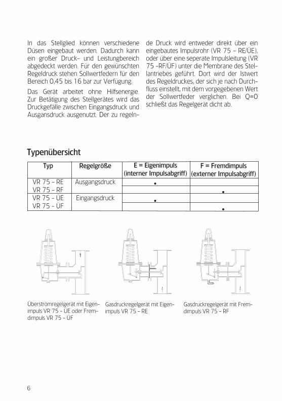
In das Stellglied können verschiedene Düsen eingebaut werden . Dadurch kann ein großer Druck- und Leistungbereich abgedeckt werden . Für den gewünschten Regeldruck stehen Sollwertfedern für den Bereich 0,45 bis 16 bar zur Verfügung .
Das Gerät arbeitet ohne Hilfsenergie . Zur Betätigung des Stellgerätes wird das Druckgefälle zwischen Eingangsdruck und Ausgansdruck ausgenutzt . Der zu regeln-
de Druck wird entweder direkt über ein eingebautes Impulsrohr (VR 75 - RE/ÜE), oder über eine seperate Impulsleitung (VR 75 -RF/ÜF) unter die Membrane des Stel-lantriebes geführt . Dort wird der Istwert des Regeldruckes, der sich je nach Durch-fluss einstellt, mit dem vorgegebenen Wert der Sollwertfeder verglichen . Bei Q=0 schließt das Regelgerät dicht ab .
Typenübersicht
Typ
VR 75 - REVR 75 - RFVR 75 - ÜEVR 75 - ÜF
Regelgröße
Ausgangsdruck
Eingangsdruck
E = Eigenimpuls(interner Impulsabgriff)
•
•
F = Fremdimpuls(externer Impulsabgriff)
•
•
Überströmregelgerät mit Eigen-impuls VR 75 - ÜE oder Frem-dimpuls VR 75 - ÜF
Gasdruckregelgerät mit Eigen-impuls VR 75 - RE
Gasdruckregelgerät mit Frem-dimpuls VR 75 - RF

2
9
3
1
10
67
4
5
8
Sollwertbereich für Gasdruckregelgeräte VR 75
Ausgangsdruck pa in bar 0,45 - 0,84 0,7 - 1,75 0,7 - 7 1,4 - 4,2 3,5 - 8,75 7 - 16
Feder-Nr.63064 (F 113)63065 (F 114)63063 (F 80)
63062 (F 36/A)63066 (F 156)63067 (F 157)
Farbegelbsilber
dunkelgrünweißbraungrau
Draht-Ø in mm3,84,57,06,38,09,5
Gasdruckregelgerät TypVR 75
7
8
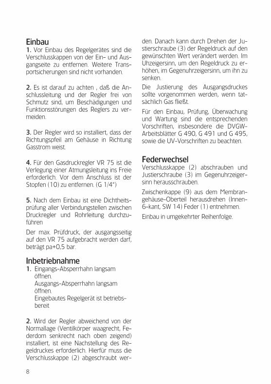
Einbau1. Vor Einbau des Regelgerätes sind die Verschlusskappen von der Ein- und Aus-gangseite zu entfernen . Weitere Trans-portsicherungen sind nicht vorhanden .
2. Es ist darauf zu achten , daß die An-schlussleitung und der Regler frei von Schmutz sind, um Beschädigungen und Funktionsstörungen des Reglers zu ver-meiden .
3. Der Regler wird so installiert, dass der Richtungspfeil am Gehäuse in Richtung Gasstrom weist .
4. Für den Gasdruckregler VR 75 ist die Verlegung einer Atmungsleitung ins Freie erforderlich . Vor dem Anschluss ist der Stopfen (10) zu entfernen . (G 1/4“)
5. Nach dem Einbau ist eine Dichtheits-prüfung aller Verbindungstellen zwischen Druckregler und Rohrleitung durchzu-führen
Der max . Prüfdruck, der ausgangsseitig auf den VR 75 aufgebracht werden darf, beträgt pa+0,5 bar .
Inbetriebnahme1. Eingangs-Absperrhahn langsam
öffnen . Ausgangs-Absperrhahn langsam öffnen . Eingebautes Regelgerät ist betriebs-bereit
2. Wird der Regler abweichend von der Normallage (Ventilkörper waagrecht, Fe-derdom senkrecht nach oben zeigend) installiert, ist eine Nachstellung des Re-geldruckes erforderlich . Hierfür muss die Verschlusskappe (2) abgeschraubt wer-
den . Danach kann durch Drehen der Ju-stierschraube (3) der Regeldruck auf den gewünschten Wert verändert werden . Im Uhzeigersinn, um den Regeldruck zu er-höhen, im Gegenuhrzeigersinn, um ihn zu senken .
Die Justierung des Ausgangsdruckes sollte vorgenommen werden, wenn tat-sächlich Gas fließt .
Für den Einbau, Prüfung, Überwachung und Wartung sind die entsprechenden Vorschriften, insbesondere die DVGW-Arbeitsblätter G 490, G 491 und G 495, sowie die UV-Vorschriften zu beachten .
FederwechselVerschlusskappe (2) abschrauben und Justierschraube (3) im Gegenuhrzeiger-sinn herausschrauben .
Zwischenkappe (9) aus dem Membran-gehäuse-Oberteil herausdrehen (Innen-6-kant, SW 14) Feder (1) entnehmen .
Einbau in umgekehrter Reihenfolge .
9
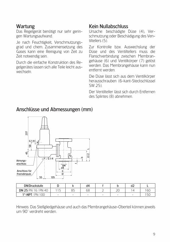
WartungDas Regelgerät benötigt nur sehr gerin-gen Wartungsaufwand .
Je nach Feuchtigkeit, Verschmutzungs-grad und chem . Zusammensetzung des Gases kann eine Reinigung von Zeit zu Zeit notwendig sein .
Durch die einfache Konstruktion des Re-gelgerätes lassen sich alle Teile leicht aus-wechseln .
Kein NullabschlussUrsache: beschädigte Düse (4), Ver-schmutzung oder Beschädigung des Ven-tiltellers (5) .
Zur Kontrolle bzw . Auswechslung der Düse und des Ventiltellers muss die Flanschverbindung zwischen Membran-gehäuse (6) und Ventilkörper (7) gelöst werden . Das Membrangehäuse kann nun entfernt werden .
Die Düse lässt sich aus dem Ventilkörper herausschrauben (6-kant-Steckschlüssel SW 25) .
Der Ventilteller lässt sich durch Entfernen des Splintes (8) abnehmen .
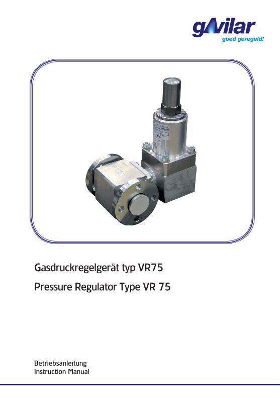
DN/Druckstufe D k d4 f b d2 LDN 25 PN 16 / PN 40 115 85 68 2 20 14 160
1“-NPT / PN 100 - - - - - - 150
Hinweis: Das Stellgliedgehäuse und auch das Membrangehäuse-Oberteil können jeweils um 90° verdreht werden .
237
Atmungs-anschluss
G 1/4
4558
13555
DNd4kD
G 1/4
Anschluss fürFremdimpuls
LL1
/2
b
d2
f
Anschlüsse und Abmessungen (mm)
DVGW-Reg . No .: NG-4301 CL 0532
CE Declaration of ConformitygAvilar BV
Kamerlingh Onnesweg 63 3316 GK Dordrecht
declares that the Product: Pressure Regulator VR75
is in conformity with the following directives:
1 . 97/23/EG module B + D category IV; Pressure Equipment Directive (PED) with EC type-examination certificate: CE-0085CP0106. The module D is supervised by Notified Body DVGW-CERT GmbH, Zertifizierungsstelle (0085); Josef-Wirmer-Str . 1-3, D-53123 Bonn .
2 . 2009/142/EC (Gas Appliances Directive) together with EN 334, with EC type-examination certificate: CE-0085CP0106. The Annex II, No . 3 is supervised by Notified Body DVGW-CERT GmbH, Zertifizierungsstelle (0085); Josef-Wirmer-Str . 1-3, D-53123 Bonn .
3 . 94/9/EG (ATEX) module A+ (Annex VIII), with marking Ref. 11501 II 2 G EEx c IIC T5 The technical documentation has been communicated to the Notified Body L .C .I .E (0081) 33, av . du Général Leclerc, 92266 Fontenay-aux-Roses France (Acknowledgment N° . LCIE 03 AR 012) .
4 . For additional electrical devices only: 2004/108/EC (electromagnetic compatibility)
Dordrecht, 06 .10 .2015
P . Klijs, Operations Manager
10
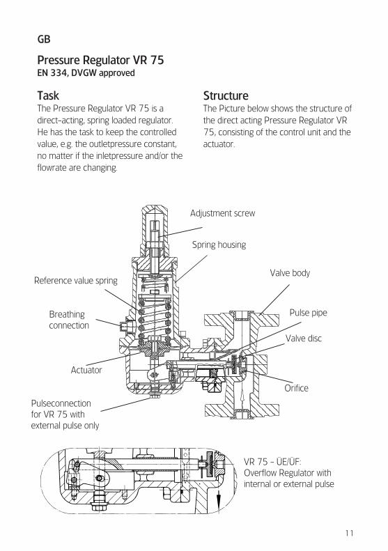
Pressure Regulator VR 75EN 334, DVGW approved
TaskThe Pressure Regulator VR 75 is a direct-acting, spring loaded regulator . He has the task to keep the controlled value, e .g . the outletpressure constant, no matter if the inletpressure and/or the flowrate are changing .
StructureThe Picture below shows the structure of the direct acting Pressure Regulator VR 75, consisting of the control unit and the actuator .
VR 75 - ÜE/ÜF:Overflow Regulator with internal or external pulse
Adjustment screw
Spring housing
Valve body
Pulse pipe
Valve disc
Orifice
Reference value spring
Breathingconnection
Actuator
Pulseconnectionfor VR 75 withexternal pulse only
11
GB
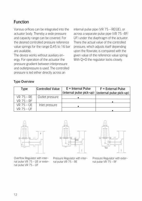
Various orifices can be integrated into the actuator body . Thereby a wide pressure and capacity range can be covered . For the desired controlled pressure reference value springs for the range 0,45 to 16 bar are available .The device works without auxiliary en-ergy . For operation of the actuator the pressure gradient between inletpressure and outletpressure is used . The controlled pressure is led either directly across an
internal pulse pipe (VR 75 - RE/ÜE), or across a separate pulse pipe (VR 75 -RF/ÜF) under the diaphragm of the actuator . There the actual value of the controlled pressure, which adjusts itself depending upon the flowrate, is compared with the given value of the reference value spring . With Q=0 the regulator locks closely .
Type Overview
Type
VR 75 - REVR 75 - RFVR 75 - ÜEVR 75 - ÜF
Controlled Value
Outlet pressure
Inlet pressure
E = Internal Pulse(internal pulse pick-up)
•
•
F = External Pulse(external pulse pick-up)
•
•
Overflow Regulator with inter-nal pulse VR 75 - ÜE or exter-nal pulse VR 75 - ÜF
Pressure Regulator with inter-nal pulse VR 75 - RE
Pressure Regulator with exter-nal pulse VR 75 - RF
Function
12
2
9
3
1
10
67
4
58
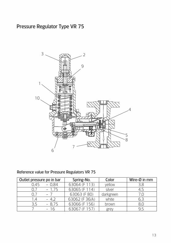
Reference value for Pressure Regulators VR 75
Outlet pressure po in bar 0,45 - 0,84 0,7 - 1,75 0,7 - 7 1,4 - 4,2 3,5 - 8,75 7 - 16
Spring-No.63064 (F 113)63065 (F 114)63063 (F 80)
63062 (F 36/A)63066 (F 156)63067 (F 157)
Coloryellowsilver
darkgreenwhitebrowngrey
Wire-Ø in mm3,84,57,06,38,09,5
Pressure Regulator Type VR 75
13
Installation1. Before installing the regulator the co-ver caps of the in- and outlet side are to be removed . Further transport locks are not existing .
2. It is to be made certain that the con-necting pipe and the regulator are free from dirt, in order to avoid damages and malfunctions of the regulator .
3. The regulator is installed in such a way that the direction arrow at the housing points toward the gasflow .
4. For the Pressure Regulator VR 75 the laying of a breathing line to outside is ne-cessary . Before the connection the plug (10) is to be removed (G 1/4“) .
5. After the Installation a leak test of all connections between pressure regulator and piping must be carried out .The max . test pressure, which may be applied to the outlet side of the VR 75, should not exceed po+0,5 bar .
Commissioning1. Open input valve slowly .Open output valve slowly Installed regula-tor is ready for operation
2. If the regulator is installed varying from the normal position (valve body horizontally, spring housing vertically facing upwards), an adjustment of the controlled pressure is necessary . Therefore the cover cap (2) must be un-
screwed . Afterwards by turning the ad-justment screw (3) the controlled pressu-re can be changed to the desired value . Clockwise in order to increase the con-trolled pressure, counterclockwise in or-der to decrease it .The adjustment of the outletpressure should be made, if actually gas flows .For the installation, check, monitoring and maintenance the appropriate regu-lations, in particular the DVGW papers G 490, G 491 and G 495 are to be con-sidered as well as the UV regulations .
Spring changeUnscrew the cover cap (2) and unscrew the adjustment screw (3) counterclock-wise .Unscrew the intermediate cap (9) from the diaphragm housing - upper part (hexagonal socket head, a/f 14) . Take out spring (1) .Installation in reverse order .
14
MaintenanceOnly little maintenance of the regulator is needed .Depending upon humidity, degree of pollution and chemical composition of the gas a cleaning occasionally can be ne-cessary .By the simple construction of the regu-lator all parts leave themselves easy to replacement .
No closing pressureCause: damaged orifice (4), contaminati-on or damage of the valve disk (5) .As a check and/or replacing of the orifice and the valve disk the flange connection between diaphragm housing (6) and valve body (7) must be loosened . The diaphragm housing can be removed now .The nozzle can be unscrewed from the valve body (hexagonal socket wrench a/f 25) .The valve disk can be taken off by removing the split pin (8) .
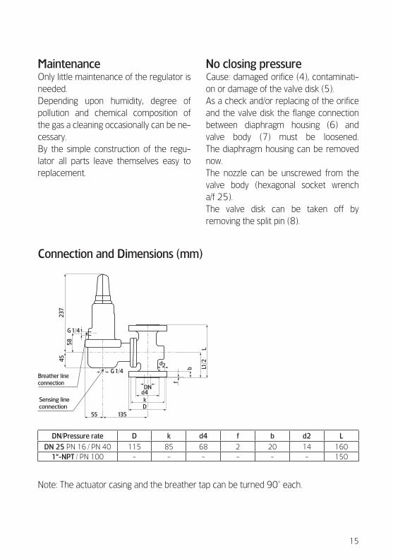
DN/Pressure rate D k d4 f b d2 L
DN 25 PN 16 / PN 40 115 85 68 2 20 14 1601“-NPT / PN 100 - - - - - - 150
Note: The actuator casing and the breather tap can be turned 90° each .
237
Breather lineconnection
G 1/4
4558
13555
DNd4kD
G 1/4
Sensing lineconnection
LL1
/2
b
d2
f
Connection and Dimensions (mm)
15
Kamerlingh Onnesweg 63, 3316 GK DordrechtPostbus 3078, 3301 DB DordrechtT 085 - 4897159 / F 085 - 4897140 / E [email protected]
WWW.GAVILAR.NL
63012 / GA-02.010-DU/EN-06.10.15 – © Copyright 2015, gAvilar, All Rights Reserved ..