Embed Size (px)
Citation preview
Manuale di assemblaggio per porte scorrevoli.
Assembly handbook for sliding doors.
Manuel pour l’assemblage pour portes coulissantes.
Zusammenbauanleitung für Schiebtürantrieb.
Manual de ensemblaje para puertas correderas.
Manual de assemblagem para portas deslizantes.
KIT REXIP1837 - rev. 2007-07-17
P
E
D
F
GB
I
DITEC S.p.A.Via Mons. Banfi, 3 - 21042 Caronno Pertusella (VA) - ITALYTel. +39 02 963911 - Fax +39 02 9650314 www.ditec.it - [email protected]
2KIT REX - IP1837
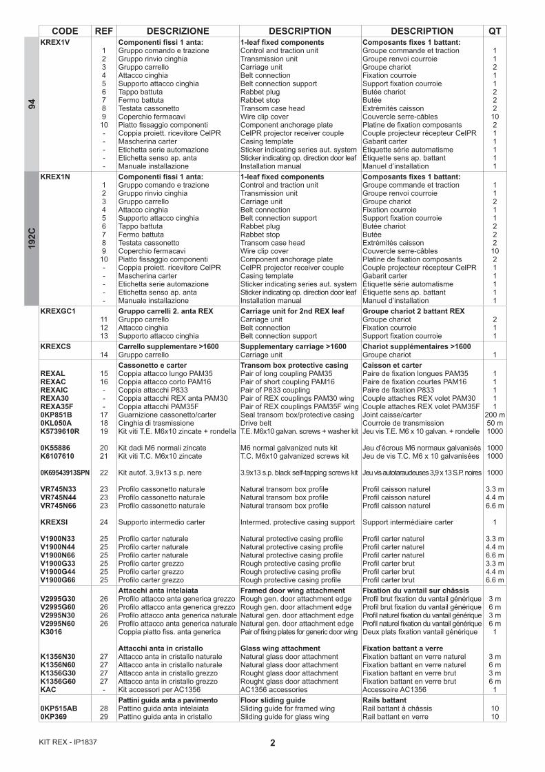
CODE REF DESCRIZIONE DESCRIPTION DESCRIPTION QTKREX1V
123456789
10-----
Componenti fissi 1 anta:Gruppo comando e trazioneGruppo rinvio cinghiaGruppo carrelloAttacco cinghiaSupporto attacco cinghiaTappo battutaFermo battutaTestata cassonettoCoperchio fermacavi Piatto fissaggio componentiCoppia proiett. ricevitore CelPRMascherina carterEtichetta serie automazioneEtichetta senso ap. anta Manuale installazione
1-leaf fixed componentsControl and traction unitTransmission unitCarriage unitBelt connectionBelt connection supportRabbet plugRabbet stopTransom case headWire clip coverComponent anchorage plateCelPR projector receiver coupleCasing templateSticker indicating series aut. system Sticker indicating op. direction door leafInstallation manual
Composants fixes 1 battant:Groupe commande et tractionGroupe renvoi courroieGroupe chariotFixation courroieSupport fixation courroieButée chariotButéeExtrémités caissonCouvercle serre-câblesPlatine de fixation composantsCouple projecteur récepteur CelPRGabarit carterÉtiquette série automatismeÉtiquette sens ap. battantManuel d’installation
11211222
10211111
KREX1N123456789
10-----
Componenti fissi 1 anta:Gruppo comando e trazioneGruppo rinvio cinghiaGruppo carrelloAttacco cinghiaSupporto attacco cinghiaTappo battutaFermo battutaTestata cassonettoCoperchio fermacavi Piatto fissaggio componentiCoppia proiett. ricevitore CelPRMascherina carterEtichetta serie automazioneEtichetta senso ap. anta Manuale installazione
1-leaf fixed componentsControl and traction unitTransmission unitCarriage unitBelt connectionBelt connection supportRabbet plugRabbet stopTransom case headWire clip coverComponent anchorage plateCelPR projector receiver coupleCasing templateSticker indicating series aut. system Sticker indicating op. direction door leafInstallation manual
Composants fixes 1 battant:Groupe commande et tractionGroupe renvoi courroieGroupe chariotFixation courroieSupport fixation courroieButée chariotButéeExtrémités caissonCouvercle serre-câblesPlatine de fixation composantsCouple projecteur récepteur CelPRGabarit carterÉtiquette série automatismeÉtiquette sens ap. battantManuel d’installation
11211222
10211111
KREXGC1111213
Gruppo carrelli 2. anta REXGruppo carrelloAttacco cinghiaSupporto attacco cinghia
Carriage unit for 2nd REX leafCarriage unitBelt connectionBelt connection support
Groupe chariot 2 battant REXGroupe chariotFixation courroieSupport fixation courroie
211
KREXCS14
Carrello supplementare >1600Gruppo carrello
Supplementary carriage >1600Carriage unit
Chariot supplémentaires >1600Groupe chariot 1
REXALREXACREXAICREXA30REXA35F0KP851B0KL050AK5739610R
0K55886K6107610
0K69543913SPN
VR745N33VR745N44VR745N66
KREXSI
V1900N33V1900N44V1900N66V1900G33V1900G44V1900G66
1516---
171819
2021
22
232323
24
252525252525
Cassonetto e carterCoppia attacco lungo PAM35Coppia attacco corto PAM16Coppia attacchi P833Coppia attacchi REX anta PAM30Coppia attacchi PAM35FGuarnizione cassonetto/carterCinghia di trasmissioneKit viti T.E. M6x10 zincate + rondella
Kit dadi M6 normali zincateKit viti T.C. M6x10 zincate
Kit autof. 3,9x13 s.p. nere
Profilo cassonetto naturaleProfilo cassonetto naturaleProfilo cassonetto naturale
Supporto intermedio carter
Profilo carter naturaleProfilo carter naturaleProfilo carter naturaleProfilo carter grezzoProfilo carter grezzoProfilo carter grezzo
Transom box protective casingPair of long coupling PAM35Pair of short coupling PAM16Pair of P833 couplingPair of REX couplings PAM30 wingPair of REX couplings PAM35F wingSeal transom box/protective casingDrive beltT.E. M6x10 galvan. screws + washer kit
M6 normal galvanized nuts kitT.C. M6x10 galvanized screws kit
3.9x13 s.p. black self-tapping screws kit
Natural transom box profile Natural transom box profileNatural transom box profile
Intermed. protective casing support
Natural protective casing profileNatural protective casing profileNatural protective casing profileRough protective casing profileRough protective casing profileRough protective casing profile
Caisson et carter Paire de fixation longues PAM35Paire de fixation courtes PAM16Paire de fixation P833Couple attaches REX volet PAM30Couple attaches REX volet PAM35FJoint caisse/carterCourroie de transmissionJeu vis T.E. M6 x 10 galvan. + rondelle
Jeu d’écrous M6 normaux galvanisésJeu de vis T.C. M6 x 10 galvanisées
Jeu vis autotaraudeuses 3,9 x 13 S.P. noires Profil caisson naturelProfil caisson naturelProfil caisson naturel
Support intermédiaire carter
Profil carter naturelProfil carter naturelProfil carter naturelProfil carter brutProfil carter brutProfil carter brut
11111
200 m50 m1000
10001000
1000
3.3 m4.4 m6.6 m
1
3.3 m4.4 m6.6 m3.3 m4.4 m6.6 m
V2995G30V2995G60V2995N30V2995N60K3016
K1356N30K1356N60K1356G30K1356G60KAC
26262626
27272727-
Attacchi anta intelaiataProfilo attacco anta generica grezzoProfilo attacco anta generica grezzoProfilo attacco anta generica naturaleProfilo attacco anta generica naturaleCoppia piatto fiss. anta generica
Attacchi anta in cristalloAttacco anta in cristallo naturaleAttacco anta in cristallo naturaleAttacco anta in cristallo grezzoAttacco anta in cristallo grezzoKit accessori per AC1356
Framed door wing attachmentRough gen. door attachment edgeRough gen. door attachment edgeNatural gen. door attachment edgeNatural gen. door attachment edgePair of fixing plates for generic door wing
Glass wing attachmentNatural glass door attachment Natural glass door attachment Rought glass door attachment Rought glass door attachmentAC1356 accessories
Fixation du vantail sur châssisProfil brut fixation du vantail génériqueProfil brut fixation du vantail génériqueProfil naturel fixation du vantail génériqueProfil naturel fixation du vantail génériqueDeux plats fixation vantail générique
Fixation battant a verreFixation battant en verre naturelFixation battant en verre naturelFixation battant en verre brutFixation battant en verre brutAccessoire AC1356
3 m6 m3 m6 m1
3 m6 m3 m6 m1
0KP515AB0KP369
2829
Pattini guida anta a pavimentoPattino guida anta intelaiataPattino guida anta in cristallo
Floor sliding guideSliding guide for framed wingSliding guide for glass wing
Rails battantRail battant à châssisRail battant en verre
1010
9419
2C

3 KIT REX - IP1837
CODE REF DESCRIZIONE DESCRIPTION DESCRIPTION QT
0KZ18REXLOKSBMREXAB
30-
32
AccessoriBlocco di sicurezzaSblocco supplementareAntipanico a batterie
AccessoriesSafety lockSupplementary release deviceAntipanic with battery
AccessoiresBlocage de sécurité avec déblocageDéblocage supplémentaireAntipanique à batterie
--1
VSP14V25 31SpazzoliniSpazzolini di tenuta
BrushesSealing brushes
BrossesBrosse d’étanchéité 2.5 m
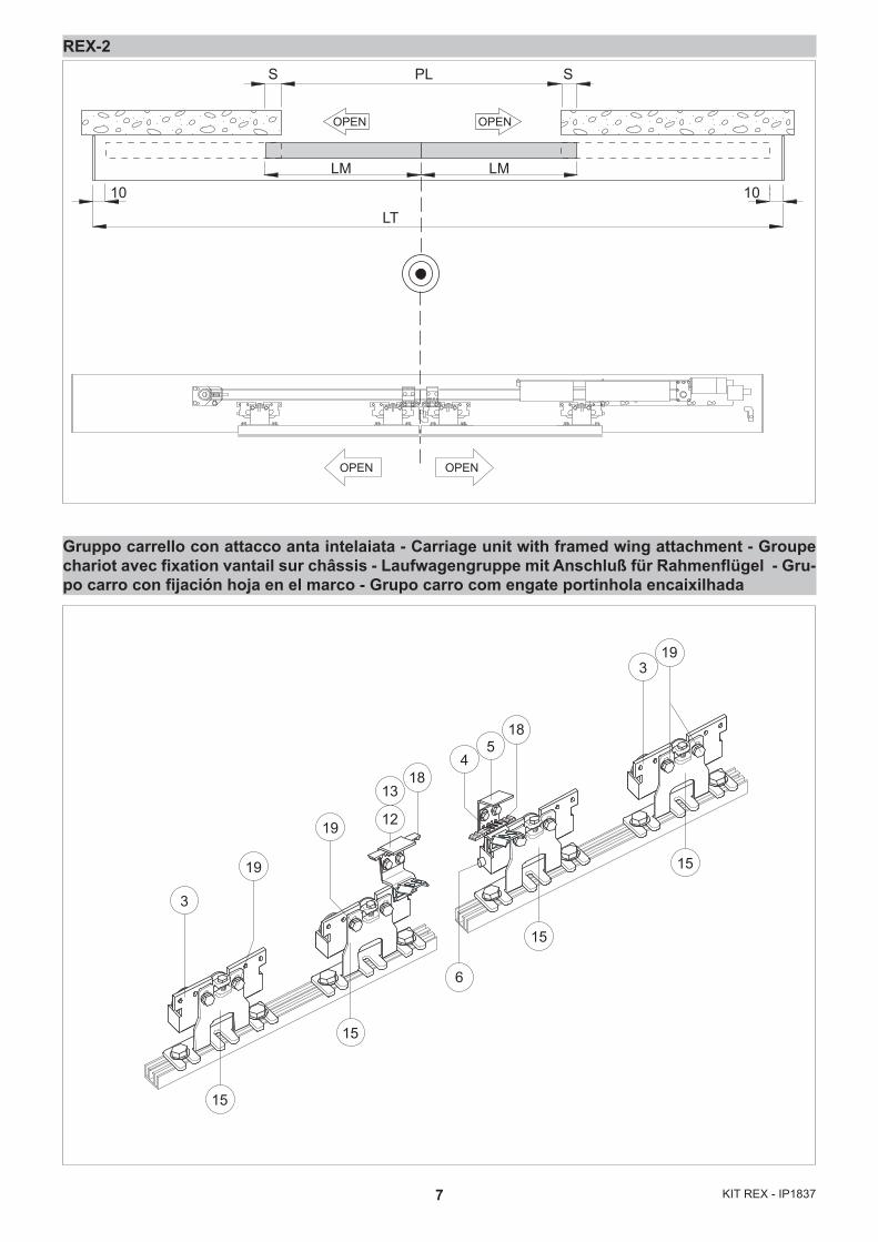
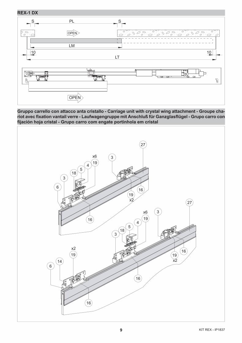
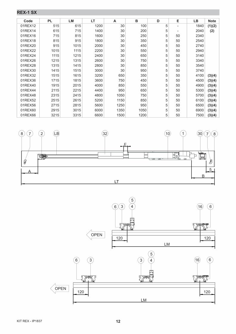
LEGENDAPL = Vano passaggio orizzontaleLM = Lunghezza anta mobileLT = Lunghezza totale automazioneLB = Lunghezza cinghiaS = Sormonto (nominale = 50)
CAPTIONPL = Horizontal passagewayLM = Mobile wing lenghtLT = Overall automatic system lenght LB = Belt lenghtS = Overlap (nominal = 50)
LÉGENDEPL = Zone de passage horizontal.LM = Longuer du vantail mobile.LT = Longuer totale automatisme.LB = Longuer de la courroie.S = Chevauchement (nominal=50)
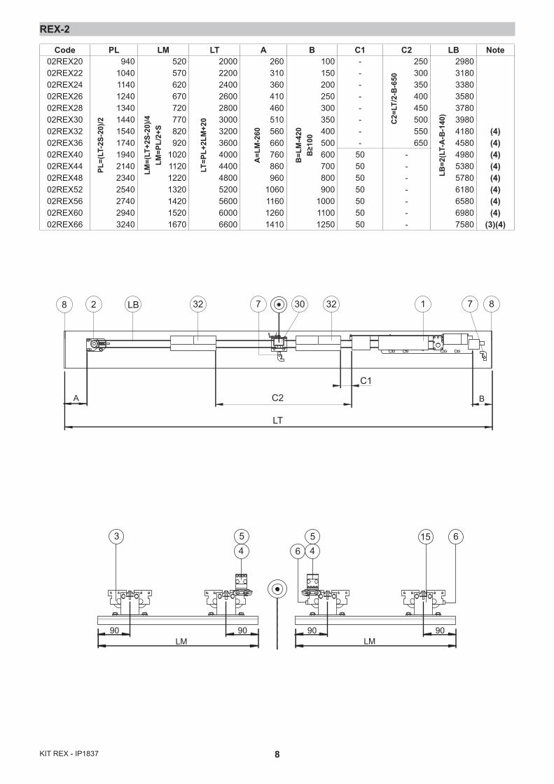
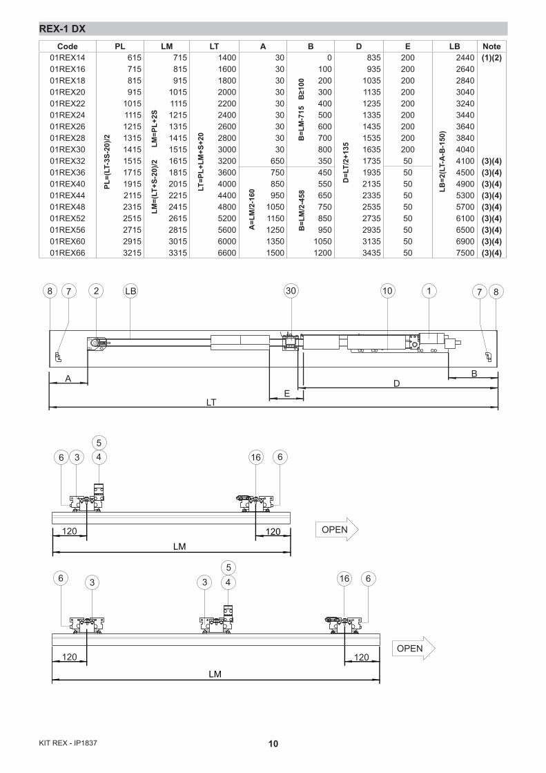
NOTE(1) Trasformatore esterno(2) Batterie esterne [32](3) Se LM>1600 aggiungere terzo carrello [14](4) Se LT≥3200 usare supporto inter-medio carter KREXSI [24]
NOTE(1) External transformer.(2) External batteries [32].(3) If LM>1600 add third carriage [14](4) If LT≥3200 use the KREXSI intermediate protective casing sup-port [24]
NOTE(1) Transformateur externe.(2) Batterie externes [32].(3) Si LM>1600 ajouter un troisiéme chariot [14](4) Si LT≥3200 utiliser support inter-médiaire du carter KREXSI [24]
4KIT REX - IP1837
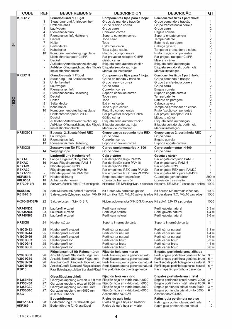
CODE REF BESCHREIBUNG DESCRIPCION DESCRIÇÃO QTKREX1V
123456789
10-----
Grundbausatz 1 FlügelSteuerung- und AntriebseinheitUmlenkeinheitLaufwagenRiemenanschlußRiemenanschluß HalterungDeckelHalterSeitendeckelKabelhalterKomponentenbefestigungsplatteLichtschrankenpaar CelPRDeckelAufkleber AntriebskennzeichnungAufkleber Öffnungsrichtung des FlügelsInstallationhandbuch
Componentes fijos para 1 hoja:Grupo de mando y tracciónGrupo reenvío correaGrupo carroConexión correaSoporte conexión correaTope carroTopeExtremos cajónTapa sujeta-cablesPlato fijo componentesPar proyector receptor CelPRGàlibo carterEtiqueta serie automatizaciónEtiqueta sentido ap. hojaManual de instalación
Componentes fixos 1 portinhola:Grupo comando e tracçãoGrupo transferência correiaGrupo carroEngate correiaSuporte engate correiaTampa batenteBatente de paragemCabeça gavetaTampa do prensador de cabosPrato fixação componentesPar project. receptor CelPRMáscara cárterEtiqueta série automaçãoEtiqueta sentido ab. portinholaManual instalação
11211222
10211111
KREX1N123456789
10-----
Grundbausatz 1 FlügelSteuerung- und AntriebseinheitUmlenkeinheitLaufwagenRiemenanschlußRiemenanschluß HalterungDeckelHalterSeitendeckelKabelhalterKomponentenbefestigungsplatteLichtschrankenpaar CelPRDeckelAufkleber AntriebskennzeichnungAufkleber Öffnungsrichtung des FlügelsInstallationhandbuch
Componentes fijos para 1 hoja:Grupo de mando y tracciónGrupo reenvío correaGrupo carroConexión correaSoporte conexión correaTope carroTopeExtremos cajónTapa sujeta-cablesPlato fijo componentesPar proyector receptor CelPRGàlibo carterEtiqueta serie automatizaciónEtiqueta sentido ap. hojaManual de instalación
Componentes fixos 1 portinhola:Grupo comando e tracçãoGrupo transferência correiaGrupo carroEngate correiaSuporte engate correiaTampa batenteBatente de paragemCabeça gavetaTampa do prensador de cabosPrato fixação componentesPar project. receptor CelPRMáscara cárterEtiqueta série automaçãoEtiqueta sentido ab. portinhola Manual instalação
11211222
10211111
KREXGC1111213
Bausatz 2. Zusatzflügel REXLaufwagenRiemenanschlußRiemenanschluß Halterung
Grupo carros segunda hoja REXGrupo carroConexión correaSoporte conexión correa
Grupo carros 2. portinhola REXGrupo carroEngate correiaSuporte engate correia
211
KREXCS14
Zusatzwagen für Flügel >1600Wagengruppe
Carros suplementarios >1600Grupo carro
Carro suplementar >1600Grupo carro 1
REXALREXACREXAICREXA30REXA35F0KP851B0KL050AK5739610R
0K55886K6107610
0K69543913SPN
VR745N33VR745N44VR745N66
KREXSI
V1900N33V1900N44V1900N66V1900G33V1900G44V1900G66
1516---
171819
2021
22
232323
24
252525252525
Laufprofil und HaubenprofilLange Flügelkupplung PAM35Kurze Flügelkupplung PAM16Flügelkupplung P833Flügelkupplung für PAM30Flügelkupplung für PAM35FHaubendichtungAntriebszahnriemenSatzverz. Sechsk. M6x10 + Unterlegsch.
Satz Muttern M6 normal / verzinktSatzverzinkte Zylinderschrauben M6x10
Satz selbstsch. 3,9x13 S.P.
Laufprofil eloxiertLaufprofil eloxiertLaufprofil eloxiert
Haubenstütze
Haubenprofil eloxiertHaubenprofil eloxiertHaubenprofil eloxiertHaubenprofil rohHaubenprofil rohHaubenprofil roh
Caja y càrter Par de fijaciòn largo PAM35Par de fijaciòn corto PAM16Par de fijaciòn P833Par empalmes REX para PAM30Par empalmes REX para PAM35FEmpaquetadura caja/cárterCorrea de transmisiónKit tornillos T.E. M6x10 galvan. + arandela
Kit tuerca M6 normales galvan.Kit tornillos T.C. M6x10 galvanizados
Kit torn. autorroscados 3.9x13 S.P. negros
Perfil caja naturalPerfil caja naturalPerfil caja natural
Soporte intermedio cárter
Perfil cárter naturalPerfil cárter naturalPerfil cárter naturalPerfil cárter brutoPerfil cárter brutoPerfil cárter bruto
Gaveta e cárterPar engate comprido PAM35Par engate curto PAM16Par engate P833Par engates REX para PAM30Par engates REX para PAM35FGuarnição gaveta/cárterCorreia de trasmissãoKit paraf. T.E. M6x10 zincadas + anilha
Kit porcas M6 normais zincadasKit parafusos T.C. M6x10 zincados
Kit autof. 3,9x13 s.p. pretas
Perfil gaveta naturalPerfil gaveta naturalPerfil gaveta natural
Suporte intermédio cárter
Perfil cárter naturalPerfil cárter naturalPerfil cárter naturalPerfil cárter brutoPerfil cárter brutoPerfil cárter bruto
11111
200 m50 m1000
10001000
1000
3.3 m4.4 m6.6 m
1
3.3 m4.4 m6.6 m3.3 m4.4 m6.6 m
V2995G30V2995G60V2995N30V2995N60K3016
K1356N30K1356N60K1356G30K1356G60KAC
26262626
27272727-
Flügelanschluß für Rahmentüren Anschlußprofil Standard-Flügel rohAnschlußprofil Standard-Flügel rohAnschlußprofil Standard-Flügel eloxiertAnschlußprofil Standard-Flügel eloxiertPaar Befestigungsplatten Standard-Flügel
GlassflügelanschlußGanzglaskupplung eloxiert 3000 mmGanzglaskupplung eloxiert 6050 mmGanzglaskupplung roh 3000 mmGanzglaskupplung roh 6050 mmAC1356 Zubehör
Fijaciòn hoja con marcoPerfil fijaciòn puerta genérica brutoPerfil fijaciòn puerta genérica brutoPerfil fijaciòn puerta genérica naturalPerfil fijaciòn puerta genérica naturalPar plato fijaciòn puerta genérica
Fijaciòn hoja en vidrioFijaciòn hoja en vidrio natur 3000Fijaciòn hoja en vidrio natur 6050Fijaciòn hoja en vidrio bruto 3000Fijaciòn hoja en vidrio bruto 6050Accessorios AC1356
Engates portinhola encaixilhadaPerfil engate portinhola genérica brutoPerfil engate portinhola genérica brutoPerfil engate portinhola genérica naturalPerfil engate portinhola genérica naturalPar chapa fix. portinhola genérica
Engates portinhola em cristalEngate portinhola cristal natural 3000Engate portinhola cristal natural 6050Engate portinhola cristal bruto 3000Engate portinhola cristal bruto 6050Acessórios AC1356
3 m6 m3 m6 m1
3 m6 m3 m6 m
0KP515AB0KP369
2829
BodenführungBodenführung für Rahmenflügel Bodenführung für Glassflügel
Rieles de guia hojaRieles de guía hoja en bastidorRieles de guía hoja en vidrio
Patins guia portinhola no pisoPatim guia portinhola encaixilhadaPatim guia portinhola em cristal
1010
9419
2C

5 KIT REX - IP1837
CODE REF BESCHREIBUNG DESCRIPCION DESCRIÇÃO QT
0KZ18REXLOKSBMREXAB
30-
32
ZubehörVerriegelung mit HandentriegelungZusätzliche HandentriegelungPanikschloß mit Batterie
AccesoriosBloque seguridad con desbloqueoDesbloqueo suplementarioAntipanico de baterìa
AcessórioSbloqueio de segurançaDesbloqueio adicionalAntipânico com baterias
--1
VSP14V25 31BürstenDichtbürste
CepilosBrosse d’étanchéité
EscovasEscovas de vedação 2.5 m
LEGENDEPL = Lichter DurchgangLM = Länge des FahrflügelLT = Gesamtlänge des AntriebsLB = Länge des RiemensS = Überlappung (Nennwert=50)
LEYENDAPL = Zona de paso horizontalLM = Longitud hoja mòvilLT = Longitud total automatizaciònLB = Longitud de la correaS = Sobrepociòn (nominal=50)
LEGENDAPL = Compart. passagem horizontalLM = Comprimento portinhola móvelLT = Comprimento total automaçãoLB = Comprimento correiaS = Sobreposição (nominal = 50)
ANMERKUNG(1) Externer Transformator.(2) Externe Batterien [32].(3) Bei LM >1600 3.Laufagen ver-wenden [14].(4) Bei Antriebslänge≥3200 Hauben-stütze KREXSI [24] verwenden
NOTE(1) Transformador externo.(2) Baterìas externas [32].(3) Si LM>1600 agregar el tercer carro [14](4) Si LT≥3200 utilizar el soporte inter-medio del cárter KREXSI [24]
NOTAS(1) Transformador externo(2) Baterias externas [32](3) Se LM>1600, adicionar terceiro carro [14](4) Se LT≥3200, usar suporte intermé-dio cárter KREXSI [24]
6KIT REX - IP1837
15 3126323
254517
323
16 27 31254517
REX
LT -
11
LT -
10
57
100 30
Ø 1
6 Ø 7
Ø 7 10
10
106
23
25
22 x6
20x2
x10 21
x2
223
89
3024
25
18
1019
x2x4
7
7
32
Fig. 1
7 KIT REX - IP1837
REX-2
Gruppo carrello con attacco anta intelaiata - Carriage unit with framed wing attachment - Groupe chariot avec fixation vantail sur châssis - Laufwagengruppe mit Anschluß für Rahmenflügel - Gru-po carro con fijación hoja en el marco - Grupo carro com engate portinhola encaixilhada
PL
LM LM
LT
10 10
S S
OPEN OPEN
OPEN OPEN
15
15
15
15
3
6
19
19
19
18
12
13
45
3
18
8KIT REX - IP1837
REX-2
28 LB 30 3232 1 87
LT
A B
C1
C2
7
LM90 90
LM90 90
3 15 645
465
Code PL LM LT A B C1 C2 LB Note02REX2002REX2202REX2402REX2602REX2802REX3002REX3202REX3602REX4002REX4402REX4802REX5202REX5602REX6002REX66
94010401140124013401440154017401940214023402540274029403240
520570620670720770820920
1020112012201320142015201670
200022002400260028003000320036004000440048005200560060006600
260310360410460510560660760860960
1060116012601410
100150200250300350400500600700800900
100011001250
--------
50505050505050
250300350400450500550650
-------
298031803380358037803980418045804980538057806180658069807580
(4)(4)(4)(4)(4)(4)(4)(4)
(3)(4)
A=L
M-2
60
B=L
M-4
20B
≥100
LT=P
L+2L
M+2
0
LM=(
LT+2
S-20
)/4LM
=PL/
2+S
PL=(
LT-2
S-20
)/2 C2=
LT/2
-B-6
50
LB=2
(LT-
A-B
-140
)
9 KIT REX - IP1837
REX-1 DX
Gruppo carrello con attacco anta cristallo - Carriage unit with crystal wing attachment - Groupe cha-riot avec fixation vantail verre - Laufwagengruppe mit Anschluß für Ganzglasflügel - Grupo carro con fijación hoja cristal - Grupo carro com engate portinhola em cristal
LM
PLS S
LT10 10
OPEN
OPEN
x6
318
54 19
3
27
27
16
x2
x2
x6
614
19
318
54
193
19
16
16
16
166
x219
10KIT REX - IP1837
REX-1 DX
2 30LB8 7 87
BA
LTE
D
110
36 16 6
6
45
5
120 120LM
LM
16 633 4
120120
OPEN
OPEN
Code PL LM LT A B D E LB Note01REX1401REX1601REX1801REX2001REX2201REX2401REX2601REX2801REX3001REX3201REX3601REX4001REX4401REX4801REX5201REX5601REX6001REX66
615715815915
10151115121513151415151517151915211523152515271529153215
715815915
101511151215131514151515161518152015221524152615281530153315
140016001800200022002400260028003000320036004000440048005200560060006600
303030303030303030
650750850950
10501150125013501500
0100200300400500600700800350450550650750850950
10501200
835935
1035113512351335143515351635173519352135233525352735293531353435
200200200200200200200200200505050505050505050
244026402840304032403440364038404040410045004900530057006100650069007500
(1)(2)
(3)(4)(3)(4)(3)(4)(3)(4)(3)(4)(3)(4)(3)(4)(3)(4)(3)(4)
PL=(
LT-3
S-20
)/2
LM=(
LT+S
-20)
/2
LM
=PL+
2S
LT=P
L+LM
+S+2
0
A=L
M/2
-160
B=L
M/2
-458
B=L
M-7
15
B≥1
00
D=L
T/2+
135
LB=2
(LT-
A-B
-150
)
11 KIT REX - IP1837
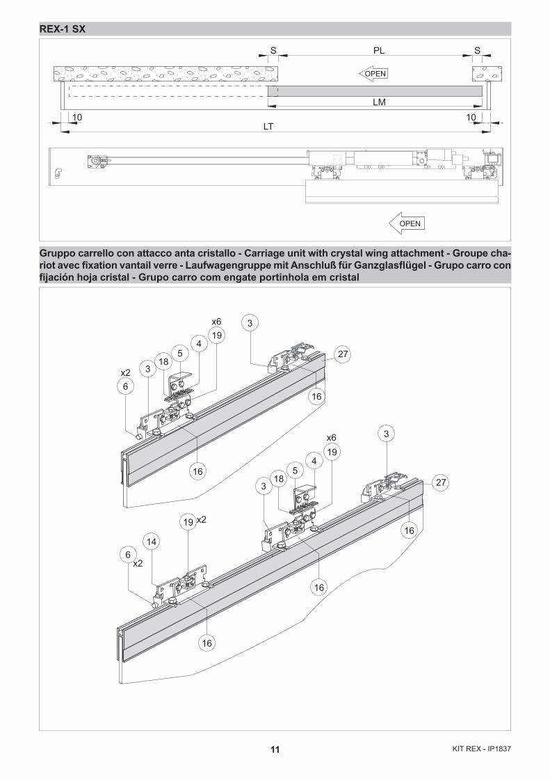
REX-1 SX
Gruppo carrello con attacco anta cristallo - Carriage unit with crystal wing attachment - Groupe cha-riot avec fixation vantail verre - Laufwagengruppe mit Anschluß für Ganzglasflügel - Grupo carro con fijación hoja cristal - Grupo carro com engate portinhola em cristal
LM
PLS S
LT10 10
OPEN
OPEN
6x2
x2
x26
14
19
318
54
3
318
54
193
16
16
16
16
27
27
x6
x619
16
12KIT REX - IP1837
REX-1 SX
2 30LB8 7 1 8710
BA
LT
5
32
E
OPEN
OPEN
36 16 6
6
45
5
120 120LM
LM
33 4
120 120
16 6
Code PL LM LT A B D E LB Note01REX1201REX1401REX1601REX1801REX2001REX2201REX2401REX2601REX2801REX3001REX3201REX3601REX4001REX4401REX4801REX5201REX5601REX6001REX66
515615715815915
10151115121513151415151517151915211523152515271529153215
615715815915
101511151215131514151515161518152015221524152615281530153315
1200140016001800200022002400260028003000320036004000440048005200560060006600
30303030303030303030
650750850950
10501150125013501500
100200250350450550650750850950350450550650750850950
10501200
5555555555555555555
--
5050505050505050505050505050505050
1840204023402540274029403140334035403740410045004900530057006100650069007500
(1)(2)(2)
(3)(4)(3)(4)(3)(4)(3)(4)(3)(4)(3)(4)(3)(4)(3)(4)(3)(4)
13 KIT REX - IP1837
32
23
3
23
917
5
4
19
15
19
25
1
1910
23
30
16
KR
EX1N
MO
TB
L
OP
EN
RP
DIP
R1
RE
SE
T
27 9 8 3 2 1 1 0
TC
on off
3
41
2
PO
WE
R
ALA
RM
+ -+ -
~ ~24 V
BAT
EN
C
-
-+
+M
otor
L N230 V~
Tran
sf.
Fuse
F1
A
Lock
Fuse
F10A
192C
1CELA
12 V
12 V
P1
SP
P2
R1
SR
R2
1 2
Ros
so -
Red
B
ianc
o - W
hite
10
+-
COM
N.O
.N.
C.
24 V
= / 0
,3 A
(max
)
Chi
usur
a au
tom
atic
a / A
utom
atic
clo
sure
; Chi
ude
/ Clo
sing
Apr
e / O
peni
n g
Sicu
rezz
a di
inve
rsio
ne /
Rev
ersa
l saf
ety
cont
act
Sto
p
Ape
rtura
par
zial
e / P
artia
l ope
nin g
Fig. 2
14KIT REX - IP1837
Usc
ita /
Out
put 2
4 V
= / 0
,5 A
Res
etE
sclu
sion
e bl
occo
/ Lo
ck e
xclu
sion
Com
une
parz
iale
/ P
artia
l com
mon
Sto
pS
icur
ezza
in c
hius
ura
/ Clo
sing
saf
ety
Sic
urez
za in
ape
rtura
/ O
peni
ng s
afet
yC
hius
ura
/ Clo
sing
Ape
rtura
lato
B /
Ope
ning
sid
e B
Ape
rtura
lato
A /
Ope
ning
sid
e A
Chi
usur
a au
tom
atic
a / A
utom
atic
clo
sure + -
MO
T
BL
CO
M
R1
DIP
TCon of
f
POW
ERAL
ARM
SA IN
DIR
+ - + - ~ ~24
V
BA T
EN
C
-
-+
+
Mot
or
L N230 V~
Tran
sf.
F1
Lock
Fuse
F10A
EL16
J
SA
FETY
EN
AB
LEC
OM
OPEN
1A
B21
22
R E M O T E
DIR
0CEL1S
LAN4S
LAN7S
LAB9
BIXLR22
TELRS
COME
TELR
COME
TELR
Converter
DMCS
DIR
PASM24
COMH-K
DIP
RFVA
VCRP
CO
ME
TELR
J
12 V
12 V
12
272829 0123A3B4689OPEN
1G141
10
2122
on
123
KR
EX1V
Fig. 3
15 KIT REX - IP1837
IAVVERTENZE GENERALI PER LA SICUREZZAIl presente manuale di assemblaggio è rivolto esclusiva-mente a personale professionalmente competente.
L’assemblaggio, i collegamenti elettrici e le regolazioni devono essere effettuati nell’osservanza della Buona Tecnica e in ot-temperanza alle norme vigenti.Leggere attentamente le istruzioni prima di iniziare l’assem-blaggio del prodotto. Un errato assemblaggio può essere fonte di pericolo.I materiali dell’imballaggio (plastica, polistirolo, ecc.) non vanno dispersi nell’ambiente e non devono essere lasciati alla portata dei bambini in quanto potenziali fonti di pericolo.Prima di iniziare l’assemblaggio verificare l’integrità del pro-dotto.
Prima di collegare l’alimentazione elettrica accertarsi che i dati di targa siano rispondenti a quelli della rete di
distribuzione elettrica.Prevedere sulla rete di alimentazione un interruttore/seziona-tore onnipolare con distanza d’apertura dei contatti uguale o superiore a 3 mm. Verificare che a monte dell’impianto elettrico vi siano un interruttore differenziale e una protezione di sovra-corrente adeguati.Per l’eventuale riparazione o sostituzione dei prodotti dovranno essere utilizzati esclusivamente ricambi originali.
La manipolazione delle parti elettroniche deve essere effettuata munendosi di bracciali conduttivi antistatici
collegati a terra.
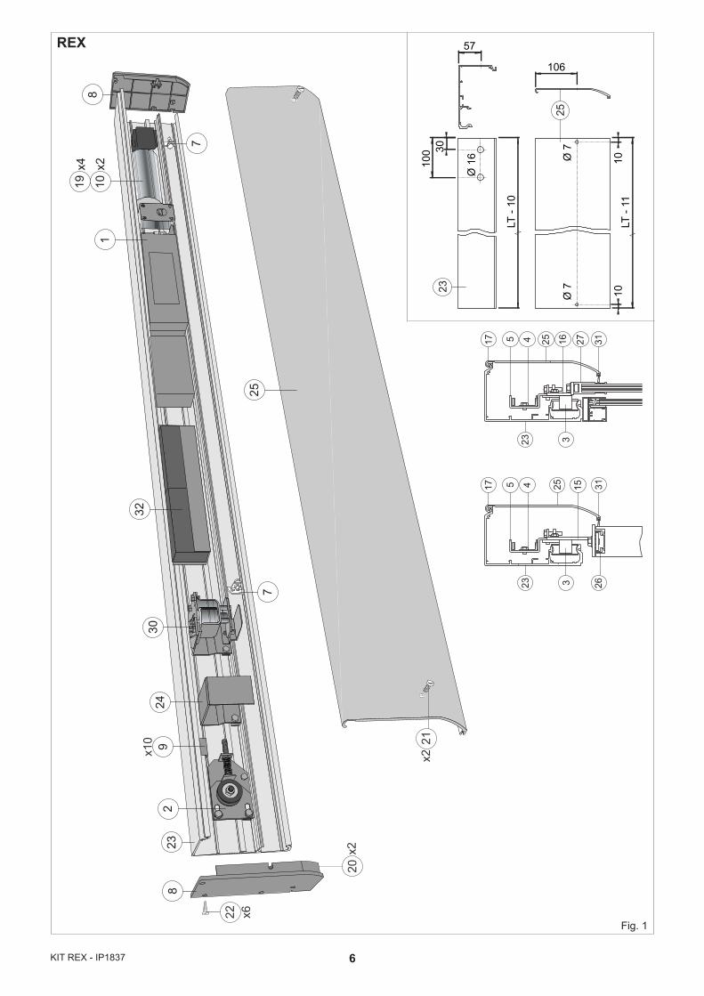
1. ASSEMBLAGGIO AUTOMAZIONE1.1 Procedura di assemblaggio- In base al tipo di automazione scelta, utilizzare la tabella
dimensionamenti (o le formule indicate) per ricavare le misure utili per l’assemblaggio dell’automazione.
- Tagliare l’alluminio del cassonetto LT-10 mm e forare come da fig. 1.
- Tagliare l’alluminio del carter LT-11 mm e forare come da fig. 1.N.B.: pulire l’alluminio da eventuali residui di taglio e in particolare pulire le guide di scorrimento carrelli.- Segnare a matita sul cassonetto le misure A, B, C, indicate
in tabella (oppure ottenute mediante formula).- Inserire all’interno della guida nr. 2 carrelli per anta; se
LM>1600 aggiungere un terzo carrello per anta (nota 1).- Verificare, facendo scorrere i carrelli all’interno della guida,
che le ruote siano prive di ammaccature (se le ruote sono ammaccate sostituirle).
- Montare le staffe attacco anta sui carrelli (come illustrato nelle figure) e fissare ai carrelli, nelle posizioni indicate in tabella, le staffe attacco cinghia e scontro blocco.
- Introdurre le piastre fissaggio [10] componenti nell’apposita guida del cassonetto vedi pagina 11 .
- Fissare i componenti (senza bloccare): gruppo comando e trazione [1], rinvio cinghia [2], blocco [30] e batterie [32], al cassonetto mediante le viti in dotazione, e seguendo le misure indicate in tabella.
N.B.: con automazione LT≥3200 fissare la staffa supporto carter [24].- Posizionare i fermi battuta [7] e i tappi battuta [6] all’interno
della guida.
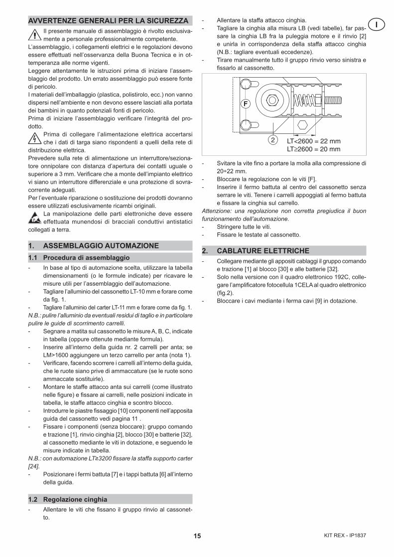
1.2 Regolazione cinghia- Allentare le viti che fissano il gruppo rinvio al cassonet-
to.
- Allentare la staffa attacco cinghia.- Tagliare la cinghia alla misura LB (vedi tabelle), far pas-
sare la cinghia LB fra la puleggia motore e il rinvio [2] e unirla in corrispondenza della staffa attacco cinghia (N.B.: tagliare eventuali eccedenze).
- Tirare manualmente tutto il gruppo rinvio verso sinistra e fissarlo al cassonetto.
- Svitare la vite fino a portare la molla alla compressione di 20÷22 mm.
- Bloccare la regolazione con le viti [F].- Inserire il fermo battuta al centro del cassonetto senza
serrare le viti. Tenere i carrelli appoggiati al fermo battuta e fissare la cinghia sul carrello.
Attenzione: una regolazione non corretta pregiudica il buon funzionamento dell’automazione.- Stringere tutte le viti.- Fissare le testate al cassonetto.
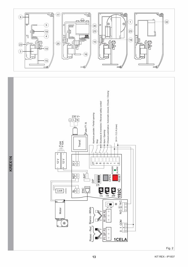
2. CABLATURE ELETTRICHE- Collegare mediante gli appositi cablaggi il gruppo comando
e trazione [1] al blocco [30] e alle batterie [32].- Solo nella versione con il quadro elettronico 192C, colle-
gare l’amplificatore fotocellula 1CELA al quadro elettronico (fig.2).
- Bloccare i cavi mediante i ferma cavi [9] in dotazione.
2
F
LT<2600 = 22 mm LT≥2600 = 20 mm
16KIT REX - IP1837
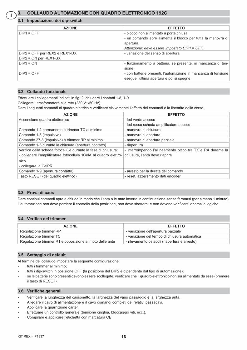
I 3. COLLAUDO AUTOMAZIONE CON QUADRO ELETTRONICO 192C3.1 Impostazione dei dip-switch
3.2 Collaudo funzionaleEffettuare i collegamenti indicati in fig. 2, chiudere i contatti 1-8, 1-9.Collegare il trasformatore alla rete (230 V~/50 Hz). Dare i seguenti comandi al quadro elettrico e verificare visivamente l’effetto dei comandi e la linearità della corsa.
3.3 Prova di caosDare continui comandi apre e chiude in modo che l’anta o le ante inverta in continuazione senza fermarsi (per almeno 1 minuto). L’automazione non deve perdere il controllo della posizione, non deve sbattere e non devono verificarsi anomalie logiche.
3.4 Verifica dei trimmer
3.5 Settaggio di defaultAl termine del collaudo impostare la seguente configurazione:- tutti i trimmer al minimo;- tutti i dip-switch in posizione OFF (la posizione del DIP2 è dipendente dal tipo di automazione);- se le batterie sono presenti devono essere scollegate, verificare che il quadro elettronico non sia alimentato da esse (premere
il tasto di RESET).
3.6 Verifiche generali- Verificare la lunghezza del cassonetto, la larghezza del vano passaggio e la larghezza anta.- Allegare il cavo di alimentazione e il cavo comandi completi dei relativi passacavi.- Applicare la guarnizione carter.- Effettuare un controllo generale (tensione cinghia, bloccaggio viti, ecc.).- Compilare e applicare l’etichetta con marcatura CE.
AZIONE EFFETTOAccensione quadro elettronico - led verde acceso
- led rosso scheda amplificatore accesoComando 1-2 permanente e trimmer TC al minimo - manovra di chiusuraComando 1-3 (impulsivo) - manovra di aperturaComando 27-3 (impulsivo) e trimmer RP al minimo - manovra di apertura parzialeComando 1-8 durante la chiusura (apertura contatto) - riaperturaVerifica della scheda fotocellule durante la fase di chiusura:- collegare l’amplificatore fotocellula 1CelA al quadro elettro-nico- collegare la CelPR
- interrompendo l’allineamento ottico tra TX e RX durante la chiusura, l’anta deve riaprire
Comando 1-9 (apertura contatto) - arresto per la durata del comandoTasto RESET (del quadro elettrico) - reset, azzeramento dati encoder
AZIONE EFFETTODIP1 = OFF - blocco non alimentato a porta chiusa
- un comando apre alimenta il blocco per tutta la manovra di apertura Attenzione: deve essere impostato DIP1 = OFF.
DIP2 = OFF per REX2 e REX1-DXDIP2 = ON per REX1-SX
- variazione del senso di apertura
DIP3 = ON - funzionamento a batteria, se presente, in mancanza di ten-sione
DIP3 = OFF - con batterie presenti, l’automazione in mancanza di tensione esegue l’ultima apertura e poi si spegne
AZIONE EFFETTORegolazione trimmer RP - variazione dell’apertura parzialeRegolazione trimmer TC - variazione del tempo di chiusura automaticaRegolazione trimmer R1 e opposizione al moto delle ante - rilevamento ostacoli (riapertura e arresto)
17 KIT REX - IP1837
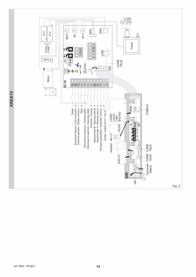
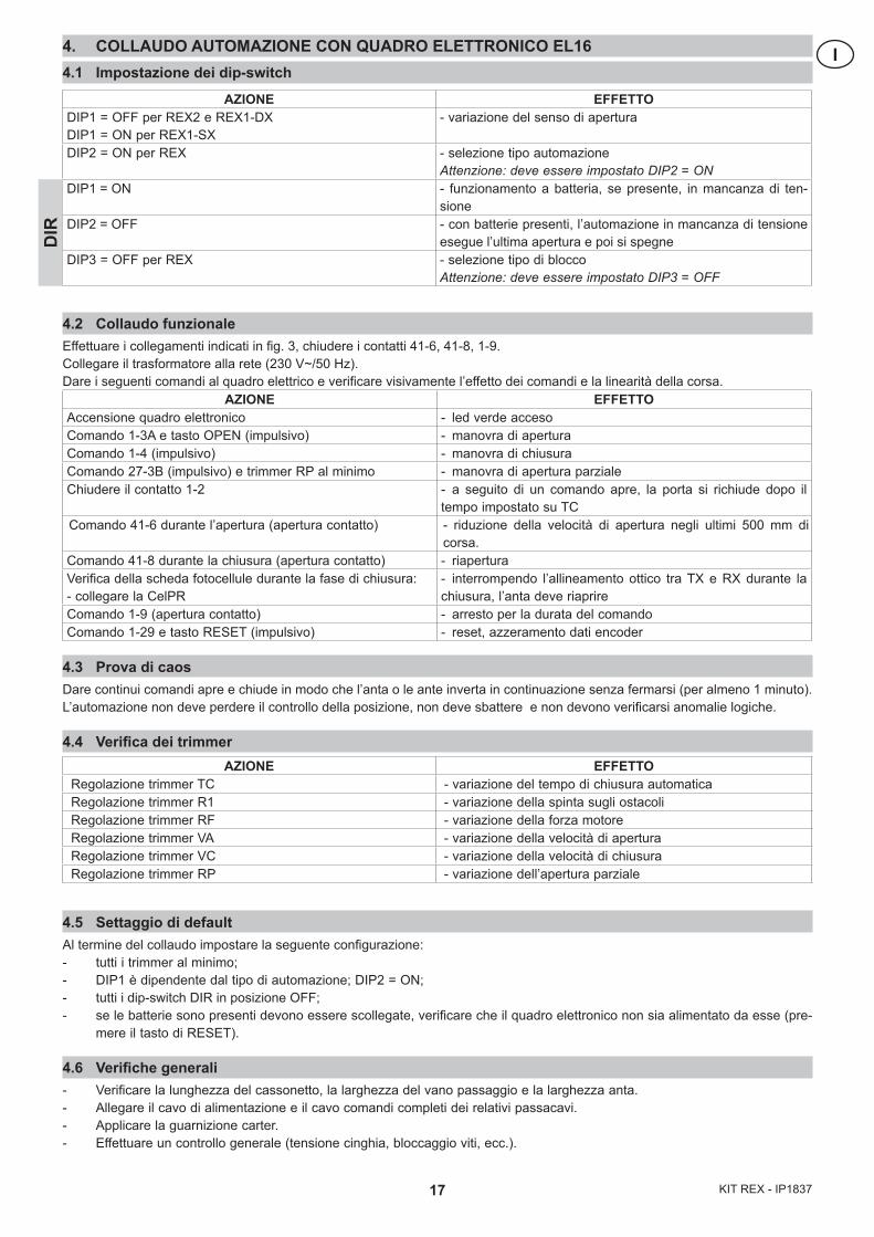
I4. COLLAUDO AUTOMAZIONE CON QUADRO ELETTRONICO EL164.1 Impostazione dei dip-switch
4.2 Collaudo funzionaleEffettuare i collegamenti indicati in fig. 3, chiudere i contatti 41-6, 41-8, 1-9.Collegare il trasformatore alla rete (230 V~/50 Hz). Dare i seguenti comandi al quadro elettrico e verificare visivamente l’effetto dei comandi e la linearità della corsa.
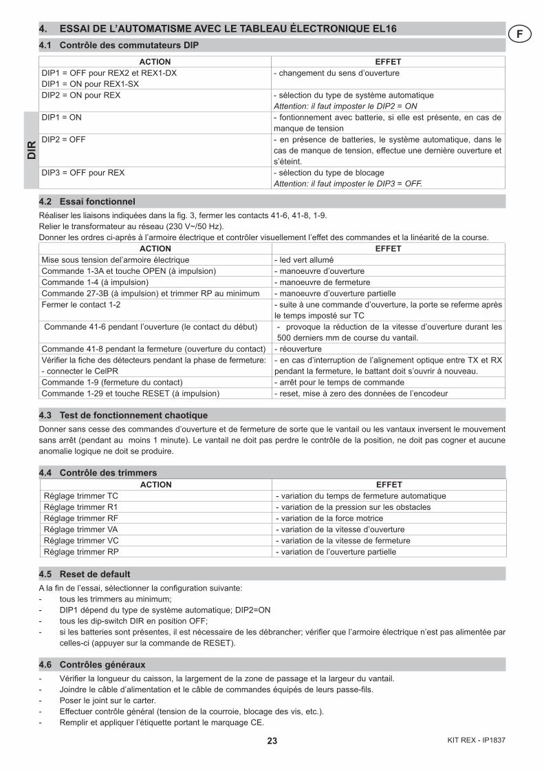
AZIONE EFFETTOAccensione quadro elettronico - led verde accesoComando 1-3A e tasto OPEN (impulsivo) - manovra di aperturaComando 1-4 (impulsivo) - manovra di chiusuraComando 27-3B (impulsivo) e trimmer RP al minimo - manovra di apertura parzialeChiudere il contatto 1-2 - a seguito di un comando apre, la porta si richiude dopo il
tempo impostato su TCComando 41-6 durante l’apertura (apertura contatto) - riduzione della velocità di apertura negli ultimi 500 mm di
corsa.Comando 41-8 durante la chiusura (apertura contatto) - riaperturaVerifica della scheda fotocellule durante la fase di chiusura:- collegare la CelPR
- interrompendo l’allineamento ottico tra TX e RX durante la chiusura, l’anta deve riaprire
Comando 1-9 (apertura contatto) - arresto per la durata del comandoComando 1-29 e tasto RESET (impulsivo) - reset, azzeramento dati encoder
4.3 Prova di caosDare continui comandi apre e chiude in modo che l’anta o le ante inverta in continuazione senza fermarsi (per almeno 1 minuto). L’automazione non deve perdere il controllo della posizione, non deve sbattere e non devono verificarsi anomalie logiche.
4.4 Verifica dei trimmer
4.5 Settaggio di defaultAl termine del collaudo impostare la seguente configurazione:- tutti i trimmer al minimo;- DIP1 è dipendente dal tipo di automazione; DIP2 = ON;- tutti i dip-switch DIR in posizione OFF;- se le batterie sono presenti devono essere scollegate, verificare che il quadro elettronico non sia alimentato da esse (pre-
mere il tasto di RESET).
4.6 Verifiche generali- Verificare la lunghezza del cassonetto, la larghezza del vano passaggio e la larghezza anta.- Allegare il cavo di alimentazione e il cavo comandi completi dei relativi passacavi.- Applicare la guarnizione carter.- Effettuare un controllo generale (tensione cinghia, bloccaggio viti, ecc.).
AZIONE EFFETTODIP1 = OFF per REX2 e REX1-DXDIP1 = ON per REX1-SX
- variazione del senso di apertura
DIP2 = ON per REX - selezione tipo automazioneAttenzione: deve essere impostato DIP2 = ON
DIP1 = ON - funzionamento a batteria, se presente, in mancanza di ten-sione
DIP2 = OFF - con batterie presenti, l’automazione in mancanza di tensione esegue l’ultima apertura e poi si spegne
DIP3 = OFF per REX - selezione tipo di bloccoAttenzione: deve essere impostato DIP3 = OFF
DIR
AZIONE EFFETTORegolazione trimmer TC - variazione del tempo di chiusura automaticaRegolazione trimmer R1 - variazione della spinta sugli ostacoliRegolazione trimmer RF - variazione della forza motoreRegolazione trimmer VA - variazione della velocità di aperturaRegolazione trimmer VC - variazione della velocità di chiusuraRegolazione trimmer RP - variazione dell’apertura parziale
18KIT REX - IP1837
GB GENERAL SAFETY PRECAUTIONSThis assembling manual is intended for professionally competent personnel only.
The assembling, the electrical connections and the settings must be completed in conformity with good workmanship and with the laws in force. Read the instructions carefully before beginning assembling the product. Incorrect assembling may be a source of danger. Packaging materials (plastics, polystyrene, etc) must not be al-lowed to litter the environment and must be kept out of the reach of children for whom they may be a source of danger. Before beginning the assembling check that the product is in perfect condition.
Before connecting to the mains check that the rating is correct for the destination power requirements.
A multipolar isolation switch with minimum contact gaps of 3 mm must be included in the mains supply. Check that upstream of the electrical installation there is an adequate differential switch and a suitable circuit breaker.For repairs or replacements of products only original spare parts must be used.
It is recommended that antistatic conductive earthed arm bands be worn when manipulating electronic parts.
1. ASSEMBLING THE AUTOMATIC SYSTEM1.1 Assembling procedure- On the basis of the type of automatic system chosen,
use the sizing table (or the formulas shown) to obtain the measurements required for the assembly of the automatic system.
- Cut the aluminium of the transom box LT-10 mm and drill a hole as shown in fig. 1.
1.3 Cut the aluminium of the protective casing LT-11 mm and drill a hole as shown in fig. 1.
Note: clean the aluminium in order to remove any traces of cut material, and clean the carriage sliding tracks in particular.- Mark measurements A, B and C shown in the table (or
calculated using the formula) on the transom box with a pencil.
- Insert 2 carriages for each leaf in the guide track; if LM>1600 add another carriage per leaf (note 1).
- Make the carriages slide along the guide tracks in order to check that the wheels are not dented (and replace them if dented).
- Fasten the leaf connection brackets on the carriages (as shown in the diagrams) and fasten the belt connection and collision locking brackets to the carriages in the positions shown in the table.
- Fit the component anchorage plates [10] in the appropriate guide track of the transom box, see page 11.
- Secure the parts (without over-tightening): command and drive unit [1], belt transmission [2], block [30] and batteries [32], to the casing with the supplied screws, and follow the measurements indicated in the table.
Note: with automatic systems LT≥3200 anchor the protective casing support bracket [24].- Position the rabbet stops [7] and rabbet plugs [6] inside
the guide track.
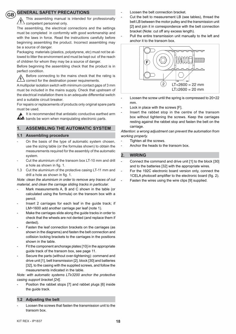
1.2 Adjusting the belt- Loosen the screws that fasten the transmission unit to the
transom box.
- Loosen the belt connection bracket.- Cut the belt to measurement LB (see tables), thread the
belt LB between the motor pulley and the transmission unit [2] and join it in correspondence with the belt connection bracket (Note: cut off any excess length).
- Pull the entire transmission unit manually to the left and anchor it to the transom box.
- Loosen the screw until the spring is compressed to 20÷22 mm.
- Lock in place with the screws [F].- Insert the rabbet stop in the centre of the transom
box without tightening the screws. Keep the carriages resting against the rabbet stop and fasten the belt on the carriage.
Attention: a wrong adjustment can prevent the automation from working properly.- Tighten all the screws. - Anchor the heads to the transom box.
2. WIRING- Connect the command and drive unit [1] to the block [30]
and to the batteries [32] with the appropriate wires.- For the 192C electronic board version only, connect the
1CELA photocell amplifier to the electronic board (fig. 2).- Fasten the wires using the wire clips [9] supplied.
2
F
LT<2600 = 22 mm LT≥2600 = 20 mm
19 KIT REX - IP1837
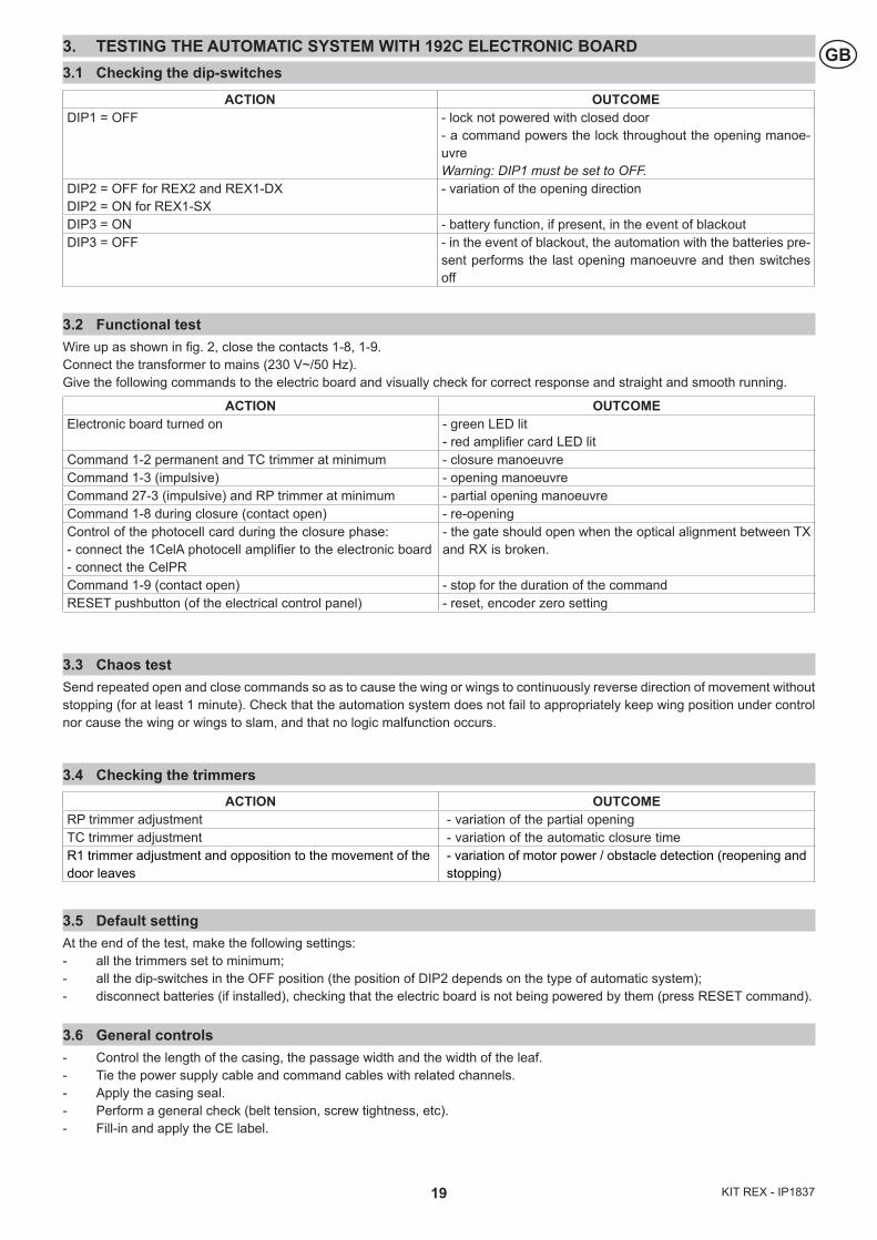
GB3. TESTING THE AUTOMATIC SYSTEM WITH 192C ELECTRONIC BOARD3.1 Checking the dip-switches
3.2 Functional testWire up as shown in fig. 2, close the contacts 1-8, 1-9. Connect the transformer to mains (230 V~/50 Hz). Give the following commands to the electric board and visually check for correct response and straight and smooth running.
3.3 Chaos testSend repeated open and close commands so as to cause the wing or wings to continuously reverse direction of movement without stopping (for at least 1 minute). Check that the automation system does not fail to appropriately keep wing position under control nor cause the wing or wings to slam, and that no logic malfunction occurs.
3.4 Checking the trimmers
3.5 Default settingAt the end of the test, make the following settings:- all the trimmers set to minimum;- all the dip-switches in the OFF position (the position of DIP2 depends on the type of automatic system);- disconnect batteries (if installed), checking that the electric board is not being powered by them (press RESET command).
3.6 General controls- Control the length of the casing, the passage width and the width of the leaf.- Tie the power supply cable and command cables with related channels.- Apply the casing seal.- Perform a general check (belt tension, screw tightness, etc). - Fill-in and apply the CE label.
ACTION OUTCOMEElectronic board turned on - green LED lit
- red amplifier card LED litCommand 1-2 permanent and TC trimmer at minimum - closure manoeuvreCommand 1-3 (impulsive) - opening manoeuvreCommand 27-3 (impulsive) and RP trimmer at minimum - partial opening manoeuvreCommand 1-8 during closure (contact open) - re-openingControl of the photocell card during the closure phase:- connect the 1CelA photocell amplifier to the electronic board - connect the CelPR
- the gate should open when the optical alignment between TX and RX is broken.
Command 1-9 (contact open) - stop for the duration of the commandRESET pushbutton (of the electrical control panel) - reset, encoder zero setting
ACTION OUTCOMEDIP1 = OFF - lock not powered with closed door
- a command powers the lock throughout the opening manoe-uvre Warning: DIP1 must be set to OFF.
DIP2 = OFF for REX2 and REX1-DXDIP2 = ON for REX1-SX
- variation of the opening direction
DIP3 = ON - battery function, if present, in the event of blackout DIP3 = OFF - in the event of blackout, the automation with the batteries pre-
sent performs the last opening manoeuvre and then switches off
ACTION OUTCOMERP trimmer adjustment - variation of the partial openingTC trimmer adjustment - variation of the automatic closure timeR1 trimmer adjustment and opposition to the movement of the door leaves
- variation of motor power / obstacle detection (reopening and stopping)
20KIT REX - IP1837
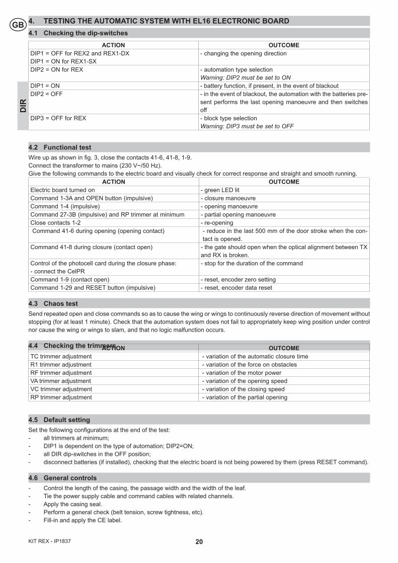
GB 4. TESTING THE AUTOMATIC SYSTEM WITH EL16 ELECTRONIC BOARD4.1 Checking the dip-switches
4.2 Functional testWire up as shown in fig. 3, close the contacts 41-6, 41-8, 1-9. Connect the transformer to mains (230 V~/50 Hz). Give the following commands to the electric board and visually check for correct response and straight and smooth running.
ACTION OUTCOMEElectric board turned on - green LED litCommand 1-3A and OPEN button (impulsive) - closure manoeuvreCommand 1-4 (impulsive) - opening manoeuvreCommand 27-3B (impulsive) and RP trimmer at minimum - partial opening manoeuvreClose contacts 1-2 - re-openingCommand 41-6 during opening (opening contact) - reduce in the last 500 mm of the door stroke when the con-
tact is opened.Command 41-8 during closure (contact open) - the gate should open when the optical alignment between TX
and RX is broken.Control of the photocell card during the closure phase:- connect the CelPR
- stop for the duration of the command
Command 1-9 (contact open) - reset, encoder zero settingCommand 1-29 and RESET button (impulsive) - reset, encoder data reset
4.3 Chaos testSend repeated open and close commands so as to cause the wing or wings to continuously reverse direction of movement without stopping (for at least 1 minute). Check that the automation system does not fail to appropriately keep wing position under control nor cause the wing or wings to slam, and that no logic malfunction occurs.
4.4 Checking the trimmers
4.5 Default settingSet the following configurations at the end of the test:- all trimmers at minimum;- DIP1 is dependent on the type of automation; DIP2=ON;- all DIR dip-switches in the OFF position;- disconnect batteries (if installed), checking that the electric board is not being powered by them (press RESET command).
4.6 General controls- Control the length of the casing, the passage width and the width of the leaf.- Tie the power supply cable and command cables with related channels.- Apply the casing seal.- Perform a general check (belt tension, screw tightness, etc). - Fill-in and apply the CE label.
ACTION OUTCOMEDIP1 = OFF for REX2 and REX1-DXDIP1 = ON for REX1-SX
- changing the opening direction
DIP2 = ON for REX - automation type selectionWarning: DIP2 must be set to ON
DIP1 = ON - battery function, if present, in the event of blackoutDIP2 = OFF - in the event of blackout, the automation with the batteries pre-
sent performs the last opening manoeuvre and then switches off
DIP3 = OFF for REX - block type selection Warning: DIP3 must be set to OFF
DIR
ACTION OUTCOMETC trimmer adjustment - variation of the automatic closure timeR1 trimmer adjustment - variation of the force on obstacles RF trimmer adjustment - variation of the motor powerVA trimmer adjustment - variation of the opening speed VC trimmer adjustment - variation of the closing speed RP trimmer adjustment - variation of the partial opening
21 KIT REX - IP1837
FCONSIGNES GENERALES DE SECURITECette notice assemblage est destinée exclusivement aux professionels qualifiès
Assemblage, le raccordement électrique et les réglages doivent être effectuée selon les régles de Bonne Tecniques er respecter la réglementation en vigueur. Lire attentivement les instructions avant de procéder à l’assemblage du produit. Une assemblage erronée peut être source de danger.Les materiaux de l’emballage (plastique, polystyréne, etc) ne doivent pas être abandonnées dans la nature et ne doivent pas être laissés à la portée des enfants, car ils sont une source po-tentielle de danger. Avant de procéder à l’assemblage, vérifier l’integrité du produit.
Avant de procéder au raccordement électrique, s’assurer que les données de la plaquette signalétique correspon-
dent à celles du réseau d’alimentation électrique. Prévoir sur le réseau d’alimentation un dispositif de coupure omnipolaire avec une distance d’ouverture des contacts égale ou supérieure à 3 mm. Vérifier qu’en amont de l’installation électrique il y ait un interrupteur différentiel ainsi qu’une protection contre des surchanges de courant adèquate. En cas de réparation ou de remplacement des produits, sed pièces de rechange originales. impérativement être utilisées.
La manipulation des parties électroniques doit être effec-tuée en mettant des bracelets conducteurs antistatiques
reliés à la terre.
1. ASSEMBLAGE DE L’AUTOMATISME1.1 Mode d’assemblage- Selon le type d’automatisme choisi utiliser les tableaux de
dimensionnement (ou les formules indiquées) pour obtenir les mesures servant à l’assemblage de l’automatisme.
- Couper l’aluminium du caisson LT-10 mm et percer comme l’indique la fig. 1.
- Couper l’aluminium du caisson LT-11 mm et percer comme l’indique la fig. 1.
Remarque: ebavurer éventuellement l’aluminium et, en par-ticulier, nettoyer les rails de coulissement des chariots.- Insérer à l’intérieur du rail 2 chariots par vantail; si LM>1600
ajouter un troisième chariot par vantail (note 1).- Vérifier, en faisant coulisser les chariots à l’intérieur du rail,
si les roues ne présentent aucune bosselure (si les roues sont bosselées, les remplacer).
- Monter les étriers de fixation du vantail sur les chariots (comme indiqué dans les figures) et fixer aux chariots, dans les positions indiquées dans le tableau, les étriers de fixation de la courroie et la butée de verrouillage.
- Introduire les plaques de fixation [10] des composants dans le rail du caisson prévu à cet effet (voir page 11) .
- Fixer les composants (sans bloquer): groupe de commande et traction [1], renvoi de courroie [2], bloc [30] et batteries [32], sur la caisse avec les vis fournies, en suivant les instructions indiquées sur le tableau.
Remarque: en cas d’automatisme LT≥3200 fixer l’étrier de support du carter [24].- Positionner les arrêts de butée [7] et les bouchons de butée
[6] à l’intérieur du rail.
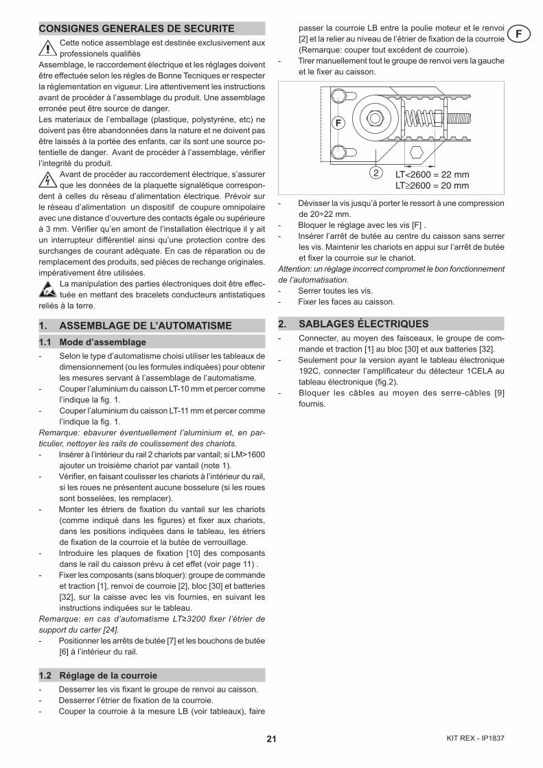
1.2 Réglage de la courroie- Desserrer les vis fixant le groupe de renvoi au caisson.- Desserrer l’étrier de fixation de la courroie.- Couper la courroie à la mesure LB (voir tableaux), faire
passer la courroie LB entre la poulie moteur et le renvoi [2] et la relier au niveau de l’étrier de fixation de la courroie (Remarque: couper tout excédent de courroie).
- Tirer manuellement tout le groupe de renvoi vers la gauche et le fixer au caisson.
- Dévisser la vis jusqu’à porter le ressort à une compression de 20÷22 mm.
- Bloquer le réglage avec les vis [F] .- Insérer l’arrêt de butée au centre du caisson sans serrer
les vis. Maintenir les chariots en appui sur l’arrêt de butée et fixer la courroie sur le chariot.
Attention: un réglage incorrect compromet le bon fonctionnement de l’automatisation.- Serrer toutes les vis.- Fixer les faces au caisson.
2. SABLAGES ÉLECTRIQUES- Connecter, au moyen des faisceaux, le groupe de com-
mande et traction [1] au bloc [30] et aux batteries [32].- Seulement pour la version ayant le tableau électronique
192C, connecter l’amplificateur du détecteur 1CELA au tableau électronique (fig.2).
- Bloquer les câbles au moyen des serre-câbles [9] fournis.
2
F
LT<2600 = 22 mm LT≥2600 = 20 mm
22KIT REX - IP1837
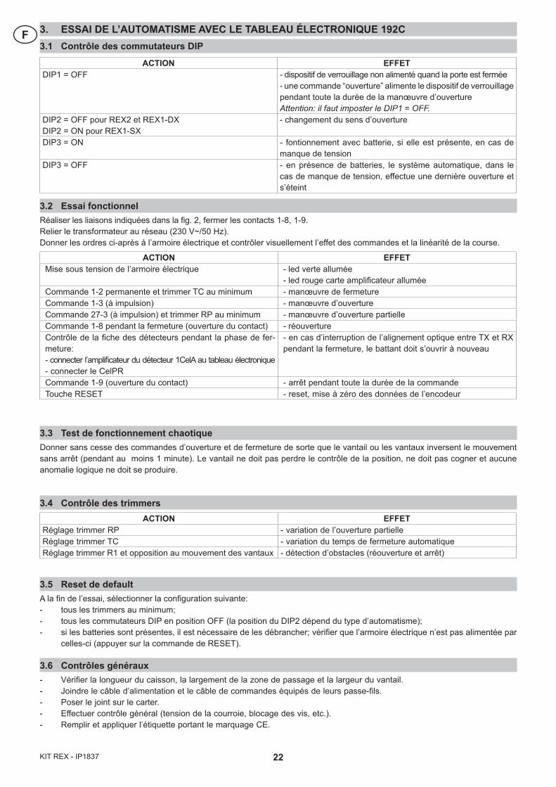
F 3. ESSAI DE L’AUTOMATISME AVEC LE TABLEAU ÉLECTRONIQUE 192C3.1 Contrôle des commutateurs DIP
3.2 Essai fonctionnelRéaliser les liaisons indiquées dans la fig. 2, fermer les contacts 1-8, 1-9. Relier le transformateur au réseau (230 V~/50 Hz). Donner les ordres ci-après à l’armoire électrique et contrôler visuellement l’effet des commandes et la linéarité de la course.
3.3 Test de fonctionnement chaotiqueDonner sans cesse des commandes d’ouverture et de fermeture de sorte que le vantail ou les vantaux inversent le mouvement sans arrêt (pendant au moins 1 minute). Le vantail ne doit pas perdre le contrôle de la position, ne doit pas cogner et aucune anomalie logique ne doit se produire.
3.4 Contrôle des trimmers
3.5 Reset de defaultA la fin de l’essai, sélectionner la configuration suivante:- tous les trimmers au minimum;- tous les commutateurs DIP en position OFF (la position du DIP2 dépend du type d’automatisme);- si les batteries sont présentes, il est nécessaire de les débrancher; vérifier que l’armoire électrique n’est pas alimentée par
celles-ci (appuyer sur la commande de RESET).
3.6 Contrôles généraux- Vérifier la longueur du caisson, la largement de la zone de passage et la largeur du vantail.- Joindre le câble d’alimentation et le câble de commandes équipés de leurs passe-fils.- Poser le joint sur le carter.- Effectuer contrôle général (tension de la courroie, blocage des vis, etc.).- Remplir et appliquer l’étiquette portant le marquage CE.
ACTION EFFETMise sous tension de l’armoire électrique - led verte allumée
- led rouge carte amplificateur alluméeCommande 1-2 permanente et trimmer TC au minimum - manœuvre de fermetureCommande 1-3 (à impulsion) - manœuvre d’ouvertureCommande 27-3 (à impulsion) et trimmer RP au minimum - manœuvre d’ouverture partielleCommande 1-8 pendant la fermeture (ouverture du contact) - réouvertureContrôle de la fiche des détecteurs pendant la phase de fer-meture:- connecter l’amplificateur du détecteur 1CelA au tableau électronique- connecter le CelPR
- en cas d’interruption de l’alignement optique entre TX et RX pendant la fermeture, le battant doit s’ouvrir à nouveau
Commande 1-9 (ouverture du contact) - arrêt pendant toute la durée de la commandeTouche RESET - reset, mise à zéro des données de l’encodeur
ACTION EFFETDIP1 = OFF - dispositif de verrouillage non alimenté quand la porte est fermée
- une commande “ouverture” alimente le dispositif de verrouillage pendant toute la durée de la manœuvre d’ouverture Attention: il faut imposter le DIP1 = OFF.
DIP2 = OFF pour REX2 et REX1-DXDIP2 = ON pour REX1-SX
- changement du sens d’ouverture
DIP3 = ON - fontionnement avec batterie, si elle est présente, en cas de manque de tension
DIP3 = OFF - en présence de batteries, le système automatique, dans le cas de manque de tension, effectue une dernière ouverture et s’éteint
ACTION EFFETRéglage trimmer RP - variation de l’ouverture partielleRéglage trimmer TC - variation du temps de fermeture automatiqueRéglage trimmer R1 et opposition au mouvement des vantaux - détection d’obstacles (réouverture et arrêt)
23 KIT REX - IP1837
F4. ESSAI DE L’AUTOMATISME AVEC LE TABLEAU ÉLECTRONIQUE EL164.1 Contrôle des commutateurs DIP
4.2 Essai fonctionnelRéaliser les liaisons indiquées dans la fig. 3, fermer les contacts 41-6, 41-8, 1-9. Relier le transformateur au réseau (230 V~/50 Hz). Donner les ordres ci-après à l’armoire électrique et contrôler visuellement l’effet des commandes et la linéarité de la course.
ACTION EFFETMise sous tension del’armoire électrique - led vert alluméCommande 1-3A et touche OPEN (à impulsion) - manoeuvre d’ouvertureCommande 1-4 (à impulsion) - manoeuvre de fermetureCommande 27-3B (à impulsion) et trimmer RP au minimum - manoeuvre d’ouverture partielleFermer le contact 1-2 - suite à une commande d’ouverture, la porte se referme après
le temps imposté sur TCCommande 41-6 pendant l’ouverture (le contact du début) - provoque la réduction de la vitesse d’ouverture durant les
500 derniers mm de course du vantail.Commande 41-8 pendant la fermeture (ouverture du contact) - réouvertureVérifier la fiche des détecteurs pendant la phase de fermeture:- connecter le CelPR
- en cas d’interruption de l’alignement optique entre TX et RX pendant la fermeture, le battant doit s’ouvrir à nouveau.
Commande 1-9 (fermeture du contact) - arrêt pour le temps de commandeCommande 1-29 et touche RESET (à impulsion) - reset, mise à zero des données de l’encodeur
4.3 Test de fonctionnement chaotiqueDonner sans cesse des commandes d’ouverture et de fermeture de sorte que le vantail ou les vantaux inversent le mouvement sans arrêt (pendant au moins 1 minute). Le vantail ne doit pas perdre le contrôle de la position, ne doit pas cogner et aucune anomalie logique ne doit se produire.
4.4 Contrôle des trimmers
4.5 Reset de defaultA la fin de l’essai, sélectionner la configuration suivante:- tous les trimmers au minimum;- DIP1 dépend du type de système automatique; DIP2=ON- tous les dip-switch DIR en position OFF;- si les batteries sont présentes, il est nécessaire de les débrancher; vérifier que l’armoire électrique n’est pas alimentée par
celles-ci (appuyer sur la commande de RESET).
4.6 Contrôles généraux- Vérifier la longueur du caisson, la largement de la zone de passage et la largeur du vantail.- Joindre le câble d’alimentation et le câble de commandes équipés de leurs passe-fils.- Poser le joint sur le carter.- Effectuer contrôle général (tension de la courroie, blocage des vis, etc.).- Remplir et appliquer l’étiquette portant le marquage CE.
ACTION EFFETDIP1 = OFF pour REX2 et REX1-DXDIP1 = ON pour REX1-SX
- changement du sens d’ouverture
DIP2 = ON pour REX - sélection du type de système automatiqueAttention: il faut imposter le DIP2 = ON
DIP1 = ON - fontionnement avec batterie, si elle est présente, en cas de manque de tension
DIP2 = OFF - en présence de batteries, le système automatique, dans le cas de manque de tension, effectue une dernière ouverture et s’éteint.
DIP3 = OFF pour REX - sélection du type de blocage Attention: il faut imposter le DIP3 = OFF.
DIR
ACTION EFFETRéglage trimmer TC - variation du temps de fermeture automatiqueRéglage trimmer R1 - variation de la pression sur les obstaclesRéglage trimmer RF - variation de la force motriceRéglage trimmer VA - variation de la vitesse d’ouvertureRéglage trimmer VC - variation de la vitesse de fermetureRéglage trimmer RP - variation de l’ouverture partielle
24KIT REX - IP1837
D ALLGEMEINE SICHERHEITSHINWEISEDas vorliegende Handbuch wendet sich ausschließlich an Fachpersonal. Die Zusammenbau, die elektrischen
Anschlüsse und die Einstellungen müssen unter Beachtung der gängigen Praxis und in Erfüllung der jeweils geltenden Vorschrif-ten durchgeführt werden. Die Anweisungen müssen vor Beginn der Zusammenbau des Produktes aufmerksam gelesen werden. Ein falscher Zusammenbau kann eine Gefahr darstellen. Das Verpackungsmaterial (Kunststoff, Styropor usw.) ordnungsgemäß entsorgen und nicht in der Reichweite von Kindern lagern, da es eine potentielle Gefahrenquelle darstellt. Vor Beginn des Zusam-menbau ist das Produkt auf Unversehrtheit zu überprüfen.
Vor dem Anschluß an das Stromnetz ist sicherzustellen, daß die Kenndaten denjenigen des Stromnetzes entsprechen.
Im Stromnetz ist ein allpoliger Schalter/Trennschalter vorzusehen, bei dem der Öffnungsabstand der Kontakte mindestens 3 mm beträgt. Es ist zu überprüfen, ob vor der elektrischen Anlage ein Differentialschalter sowie ein entsprechender Überstromschutz vorhanden ist. Im Falle einer Reparatur oder eines Austauschs der Produkte sind ausschließlich Original-Ersatzteile zu verwenden. Die elektronischen Teile dürfen nur angefasst werden, wenn die
betreffende Person mit leitfähigen antistatischen, geerdeten Manschetten ausgestattet ist.
1. ZUSAMMENBAU DES TÜRANTRIEBS1.1 Montageverfahren- Je nach Typ der gewählten Automatisierung, verwenden
Sie die Maßtabellen (oder die angegebenen Formeln) zum Ablesen der passenden Maße für den Zusammenbau der Automatisierung.
- Schneiden Sie das Aluminium des Laufprofils LT-10 mm zu und bohren Sie gemäß Abb. 1.
- Schneiden Sie das Aluminium des Haubenprofils LT-11 mm zu und bohren Sie gemäß Abb. 1.
Anm.: säubern sie das Aluminium von eventuellen Spänen und reinigen Sie insbesondere die Laufflächen der Rollwagen.- Zeichnen Sie mit einem Bleistift die in der Tabelle ange-
gebenen (oder mittels Formel gefundenen) Maße A, B, C an.
- 2 Laufwagen pro Türflügel in die das Laufprofil einsetzen; bei LM>1600 einen dritten Laufwagen pro Türflügel vorsehen (Anm. 1).
- Durch Verschieben der Laufwagen in der Führungsschiene prüfen, ob die Rollen Druckstellen aufweisen (wenn Druckstellen vorhanden sind, Rollen austauschen).
- Flügelanschlüsse an die Laufwagen montieren (wie in der Abbildung dargestellt). Die Zahnriemenbefestigungen und den Verriegelungsanschlag in den in der Tabelle angegebenen Positionen an den Laufwagen befestigen.
- Grundträger [10] für die Komponenten in der entsprechenden Führungsschiene des Laufprofils einsetzen. Siehe Seite 11.
- Die Komponenten Steuergruppe und Antrieb[1], Riemenumlenkung[2], Blockierung [30] und Batterien[32] durch die mitgelieferten Schrauben an dem Container befestigen (ohne sie zu blockieren), wobei man sich an die in der Tabelle angegebenen Maße halten muss.
Anm.: bei Antrieben mit LT≥3200 Haubenstütze [24] anbringen.- Die Anschläge [7] und Anschlagpuffer [6] in die
Führungsschiene setzen.
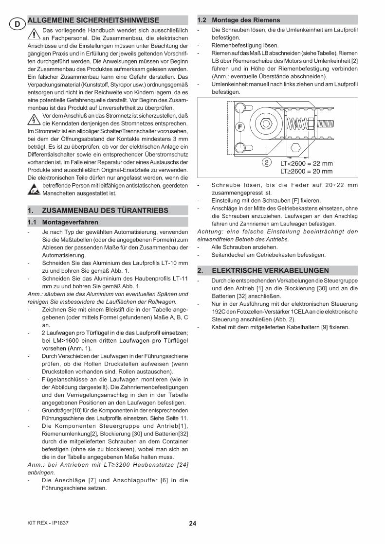
1.2 Montage des Riemens- Die Schrauben lösen, die die Umlenkeinheit am Laufprofil
befestigen.- Riemenbefestigung lösen.- Riemen auf das Maß LB abschneiden (siehe Tabelle), Riemen
LB über Riemenscheibe des Motors und Umlenkeinheit [2] führen und in Höhe der Riemenbefestigung verbinden (Anm.: eventuelle Überstände abschneiden).
- Umlenkeinheit manuell nach links ziehen und am Laufprofil befestigen.
- Schraube lösen, bis die Feder auf 20÷22 mm zusammengepresst ist.
- Einstellung mit den Schrauben [F] fixieren.- Anschläge in der Mitte des Getriebekastens einsetzen, ohne
die Schrauben anzuziehen. Laufwagen an den Anschlag fahren und Zahnriemen am Laufwagen befestigen.
Achtung: eine falsche Einstellung beeinträchtigt den einwandfreien Betrieb des Antriebs.- Alle Schrauben anziehen.- Seitendeckel am Getriebekasten befestigen.
2. ELEKTRISCHE VERKABELUNGEN- Durch die entsprechenden Verkabelungen die Steuergruppe
und den Antrieb [1] an die Blockierung [30] und an die Batterien [32] anschließen.
- Nur in der Ausführung mit der elektronischen Steuerung 192C den Fotozellen-Verstärker 1CELA an die elektronische Steuerung anschließen (Abb. 2).
- Kabel mit dem mitgelieferten Kabelhaltern [9] fixieren.
2
F
LT<2600 = 22 mm LT≥2600 = 20 mm
25 KIT REX - IP1837
D3. TEST DER AUTOMATISIERUNG MIT STEUERUNG 192C3.1 Überprüfung der Dip-Switch
3.2 FunktionstestStellen Sie die in Abb. 2 bezeichneten Anschlüsse her und überprüfen Sie die Kontakte 1-8, 1-9. Schließen Sie den Transformator an das Netz (230 V~/50 Hz) an. Geben Sie die nachfolgenden Befehle an die Steuerung und stellen Sie durch Sichtprüfung die Wirksamkeit der Befehle und die Gleichmäßigkeit des Laufes sicher.
3.3 Chaos-PrüfungGeben Sie kontinuierlich Öffnungs- und Schließbefehle, so dass sich ständig die Laufrichtung des Flügels oder der Flügel ändert (für mindestens 1 Minute). Die Automatisierung darf die Kontrolle der Positionierung nicht verlieren, und es dürfen keine logischen Störungen eintreten.
3.4 Kontrolle der Trimmer
3.5 StandardeinstellungenStellen Sie am Ende des Tests die folgende Konfiguration ein:- alle Trimmer auf Minimum;- alle DIP-Schalter stehen in OFF-Position (die Position von DIP2 hängt von der Art des Antriebs ab);- wenn ein Akkupack vorhanden ist, so muß dieser abgetrennt werden. Stellen Sie sicher, dass die Steuerung nicht von letzteren
gespeist wird (die Taste RESET drücken).
3.6 Allgemeine Kontrollen- Die Containerlänge, die Breite des Durchgangsraums und die Türbreite prüfen.- Das Stromkabel und das Kabel für die Steuerungen komplett mit den entsprechenden Kabeldurchgängen beifügen. - Die Gehäusedichtung anbringen.- Eine allgemeine Kontrolle vornehmen (Riemenspannung, Schraubenblockierung usw.).- Das Etikett mit der CE-Markierung ausfüllen und anbringen.
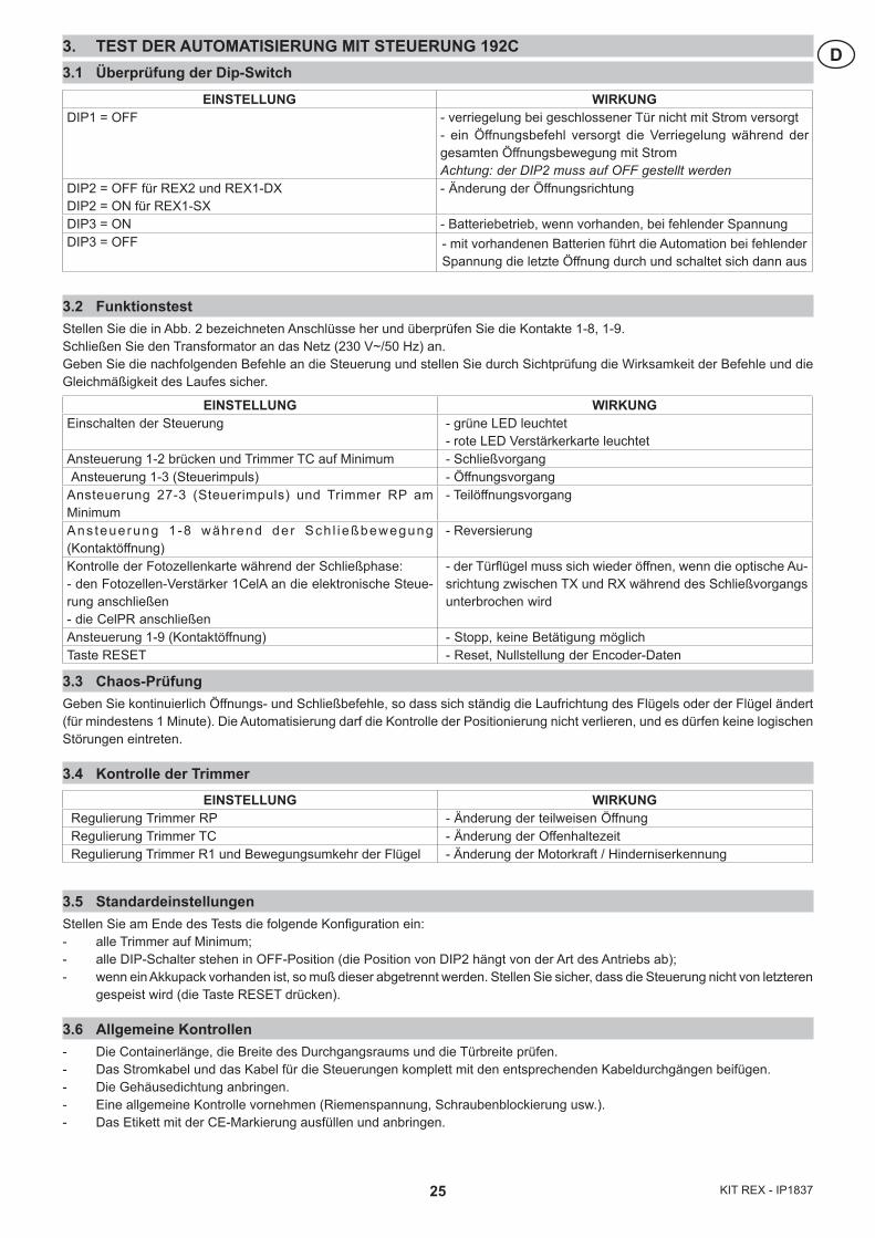
EINSTELLUNG WIRKUNGEinschalten der Steuerung - grüne LED leuchtet
- rote LED Verstärkerkarte leuchtetAnsteuerung 1-2 brücken und Trimmer TC auf Minimum - SchließvorgangAnsteuerung 1-3 (Steuerimpuls) - Öffnungsvorgang
Ansteuerung 27-3 (Steuerimpuls) und Trimmer RP am Minimum
- Teilöffnungsvorgang
Ans teuerung 1 -8 während der Sch l ießbewegung (Kontaktöffnung)
- Reversierung
Kontrolle der Fotozellenkarte während der Schließphase: - den Fotozellen-Verstärker 1CelA an die elektronische Steue-rung anschließen - die CelPR anschließen
- der Türflügel muss sich wieder öffnen, wenn die optische Au-srichtung zwischen TX und RX während des Schließvorgangs unterbrochen wird
Ansteuerung 1-9 (Kontaktöffnung) - Stopp, keine Betätigung möglichTaste RESET - Reset, Nullstellung der Encoder-Daten
EINSTELLUNG WIRKUNGDIP1 = OFF - verriegelung bei geschlossener Tür nicht mit Strom versorgt
- ein Öffnungsbefehl versorgt die Verriegelung während der gesamten Öffnungsbewegung mit StromAchtung: der DIP2 muss auf OFF gestellt werden
DIP2 = OFF für REX2 und REX1-DXDIP2 = ON für REX1-SX
- Änderung der Öffnungsrichtung
DIP3 = ON - Batteriebetrieb, wenn vorhanden, bei fehlender Spannung DIP3 = OFF - mit vorhandenen Batterien führt die Automation bei fehlender
Spannung die letzte Öffnung durch und schaltet sich dann aus
EINSTELLUNG WIRKUNGRegulierung Trimmer RP - Änderung der teilweisen ÖffnungRegulierung Trimmer TC - Änderung der OffenhaltezeitRegulierung Trimmer R1 und Bewegungsumkehr der Flügel - Änderung der Motorkraft / Hinderniserkennung
26KIT REX - IP1837
D 4. TEST DER AUTOMATISIERUNG MIT STEUERUNG EL164.1 Überprüfung der Dip-Switch
4.2 FunktionstestStellen Sie die in Abb. 3 bezeichneten Anschlüsse her und überprüfen Sie die Kontakte 41-6, 41-8, 1-9. Schließen Sie den Transformator an das Netz (230 V~/50 Hz) an. Geben Sie die nachfolgenden Befehle an die Steuerung und stellen Sie durch Sichtprüfung die Wirksamkeit der Befehle und die Gleichmäßigkeit des Laufes sicher.
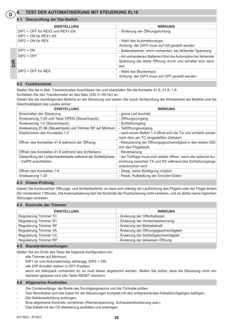
EINSTELLUNG WIRKUNGEinschalten der Steuerung - grüne Led leuchtetAnsteuerung 1-3A und Taste OPEN (Steuerimpuls) - ÖffnungsvorgangAnsteuerung 1-4 (Steuerimpuls) - SchließvorgangAnsteuerung 27-3B (Steuerimpuls) und Trimmer RP auf Minimum - TeilöffnungsvorgangÜberbrücken des Kontaktes 1-2 - nach einem Befehl 1-3 öffnet sich die Tür und schließt wieder
nach dem am TC eingestellten ZeitraumÖffnen des Kontaktes 41-6 während der Öffnung - Reduzierung der Öffnungsgeschwindigkeit in den letzten 500
mm des FlügellaufsÖffnen des Kontaktes 41-8 während des Schließens - ReversierungÜberprüfung der Lichtschrankenkarte während der Schließphase: - CelPR anschließen
- der Türflügel muss sich wieder öffnen, wenn die optische Au-srichtung zwischen TX und RX während des Schließvorgangs unterbrochen wird
Öffnen des Kontaktes 1-9 - Stopp, keine Betätigung möglichAnsteuerung 1-29 - Reset, Nullstellung der Encoder-Daten
4.3 Chaos-PrüfungGeben Sie kontinuierlich Öffnungs- und Schließbefehle, so dass sich ständig die Laufrichtung des Flügels oder der Flügel ändert (für mindestens 1 Minute). Die Automatisierung darf die Kontrolle der Positionierung nicht verlieren, und es dürfen keine logischen Störungen eintreten.
4.4 Kontrolle der Trimmer
4.5 StandardeinstellungenStellen Sie am Ende des Tests die folgende Konfiguration ein:- alle Trimmer auf Minimum;- DIP1 ist vom Automationstyp abhängig; DIP2 = ON;- alle DIP-Schalter stehen in OFF-Position;- wenn ein Akkupack vorhanden ist, so muß dieser abgetrennt werden. Stellen Sie sicher, dass die Steuerung nicht von
letzteren gespeist wird (die Taste RESET drücken).
4.6 Allgemeine Kontrollen- Die Containerlänge, die Breite des Durchgangsraums und die Türbreite prüfen.- Das Stromkabel und das Kabel für die Steuerungen komplett mit den entsprechenden Kabeldurchgängen beifügen. - Die Gehäusedichtung anbringen.- Eine allgemeine Kontrolle vornehmen (Riemenspannung, Schraubenblockierung usw.).- Das Etikett mit der CE-Markierung ausfüllen und anbringen.
EINSTELLUNG WIRKUNGDIP1 = OFF für REX2 und REX1-DXDIP1 = ON für REX1-SX
- Änderung der Öffnungsrichtung
DIP2 = ON für REX - Wahl des Automationstyps. Achtung: der DIP2 muss auf ON gestellt werden
DIP1 = ON - Batteriebetrieb, wenn vorhanden, bei fehlender SpannungDIP2 = OFF - mit vorhandenen Batterien führt die Automation bei fehlender
Spannung die letzte Öffnung durch und schaltet sich dann aus
DIP3 = OFF für REX - Wahl des Blockiertyps Achtung: der DIP3 muss auf OFF gestellt werden
DIR
EINSTELLUNG WIRKUNGRegulierung Trimmer TC - Änderung der OffenhaltezeitRegulierung Trimmer R1 - Änderung der HinderniserkennungRegulierung Trimmer RF - Änderung der BetriebskraftRegulierung Trimmer VA - Änderung der Öffnungsgeschwindigkeit Regulierung Trimmer VC - Änderung der SchließgeschwindigkeitRegulierung Trimmer RP - Änderung der teilweisen Öffnung
27 KIT REX - IP1837
EADVERTENCIAS GENERALES DE SEGURIDADEl presente manual de ensemblado està destinado exclu-sivamente a profesionales calificados. El ensemblado, las
conexiones eléctricas y los ajustes de regulaciòn deben ser he-chos aplicando las reglas técnicas aceptadas y de conformidad con las normas vigentes. Leer atentamente las instrucciones antes de comenzar la ensem-blado del producto. Un ensemblado incorrecta puede ser causa de peligro. El material de embalaje (plàstico, poliestirol, etc) debe desecharse sin causar daño al medio ambiente y mantenerse fuera del alcance de los niños, porque es una potencial fuente de peligro. Antes de comenzar la ensemblado. verificar que el producto estè integro.
Antes de conectar la alimentaciòn elèctrica, comprobar que la potencia indicada corresponda a la de la red de
distribuciòn. Instalar en lar ed de alimentaciòn un interruptor secconador omnipolar con distancia de apertura entre los con-tactos igual o superior a 3 mm. Comprobar la presencia de un interruptor diferencial y una protecciòn contra sobracorriente adecuados. Para cualquier reparaciòn o sustituciòn del producto, utilizar exclusivamente repuestos originales.
Proveerse de brazaletes conductores antiéstaticos conectados a tierra para la manipolaciòn de las partes
electrònicas.
1. ENSAMBLADO DE LA AUTOMATIZACIÓN1.1 Procedimiento de ensamblado- En base al tipo de automatización elegida, utilizar las
tablas de dimensionamientos (o las fórmulas indicadas) para obtener las medidas útiles para el ensamblado de la automatización.
- Cortar el aluminio del cajón LT-10 mm y perforar como indicado en la fig. 1.
- Cortar el aluminio del cárter LT-11 mm y perforar como indicado en la fig. 1.
Nota: limpiar el aluminio de eventuales residuos del corte y en particular limpiar las guías de desplazamiento de los carros.- Marcar con un lápiz, en el cajón, las medidas A, B, C in-
dicadas en la tabla (o bien obtenidas mediante fórmula).- Introducir al interior de la guía 2 carros por hoja; si
LM>1600, agregar un tercer carro por hoja (nota 1). - Verificar, desplazando los carros al interior de la guía, que
las ruedas no presenten abolladuras (sustituir las ruedas si están abolladas).
- Montar los estribos de fijación de la hoja en los carros (tal como se ilustra en las figuras) y fijar a los carros, en las posiciones que se indican en la tabla, los estribos de fijación de la correa y el tope de bloqueo.
- Introducir las placas de fijación [10] de los componentes en la respectiva guía del cajón (ver página 11).
- Fijar los componentes (sin bloquear): grupo comando y tracción [1], reenvío correa [2], bloque [30] y baterías [32], al contenedor a través los tornillos en dotación, y siguiendo las medidas indicadas en la tabla.
Nota: en caso de automatización LT≥3200 fijar el estribo de soporte cárter [24].- Posicionar los topes [7] y los tapones de tope [6] al interior
de la guía.
1.2 Regulación de la correa- Aflojar los tornillos que fijan el grupo de transmisión al
cajón.
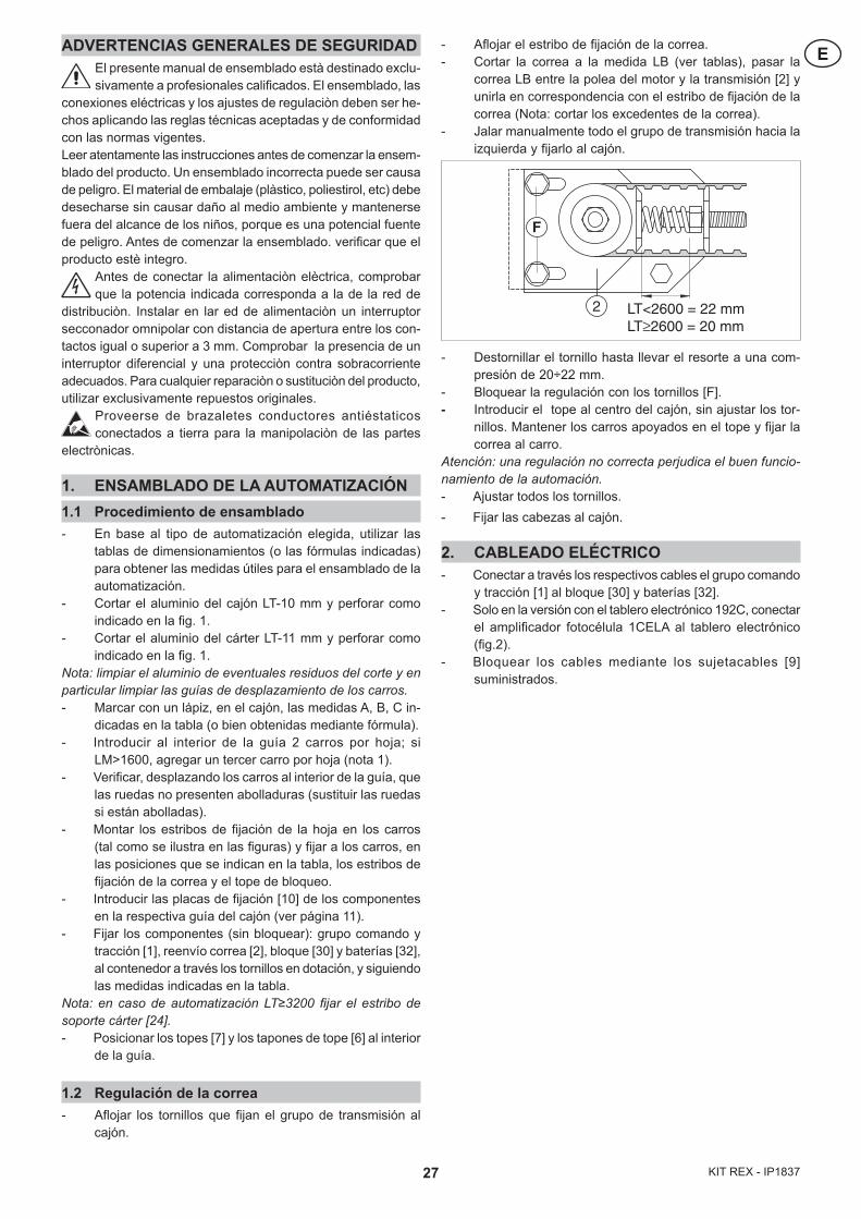
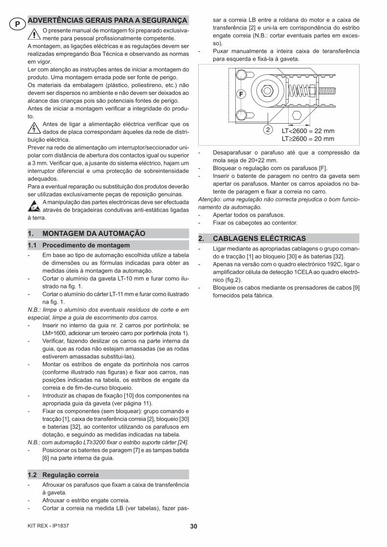
- Aflojar el estribo de fijación de la correa.- Cortar la correa a la medida LB (ver tablas), pasar la
correa LB entre la polea del motor y la transmisión [2] y unirla en correspondencia con el estribo de fijación de la correa (Nota: cortar los excedentes de la correa).
- Jalar manualmente todo el grupo de transmisión hacia la izquierda y fijarlo al cajón.
- Destornillar el tornillo hasta llevar el resorte a una com-presión de 20÷22 mm.
- Bloquear la regulación con los tornillos [F].- Introducir el tope al centro del cajón, sin ajustar los tor-
nillos. Mantener los carros apoyados en el tope y fijar la correa al carro.
Atención: una regulación no correcta perjudica el buen funcio-namiento de la automación.- Ajustar todos los tornillos.- Fijar las cabezas al cajón.
2. CABLEADO ELÉCTRICO- Conectar a través los respectivos cables el grupo comando
y tracción [1] al bloque [30] y baterías [32].- Solo en la versión con el tablero electrónico 192C, conectar
el amplificador fotocélula 1CELA al tablero electrónico (fig.2).
- Bloquear los cables mediante los sujetacables [9] suministrados.
2
F
LT<2600 = 22 mm LT≥2600 = 20 mm
28KIT REX - IP1837
E 3. ENSAYO DE LA AUTOMATIZACIÓN CON TABLERO ELECTRÓNICO 192C3.1 Verificación de los conmutadores
3.2 Ensayo funcionalEfectuar las conexiones indicadas en la fig. 2, cerrar los contactos 1-8, 1-9. Conectar el transformador a la red (230 V~/50 Hz). Dar los siguientes mandos al tablero eléctrico y verificar visualmente el efecto de los mandos y la linealidad de la carrera.
3.3 Test de funcionamiento caóticoDar sin cesar mandos de abertura y de cierre para que la hoja o las hojas inviertan el movimiento sin detenerse (al menos durante 1 minuto). La hoja no debe perder el control de la posición, no debe golpear y no se deberán verificar anomalías lógicas.
3.4 Verificación de los trimmers
3.5 Configuración por defectoAl término del ensayo programar la siguiente configuración:- todos los trimmers al minimo;- todos los conmutadores DIP en posición OFF (la posición del DIP2 depende del tipo de automatización);- si las baterías se encuentran presentes, deberán ser desconectadas. Verificar que el tablero eléctrico no esté siendo ali-
mentado por éstas (presionar el mando de RESET).
3.6 Verificaciones generales- Verificar la longitud del cajón, el ancho de la zona de paso y el ancho de la hoja.- Acoplar el cable de alimentación y el cable de mandos con sus respectivos pasacables.- Aplicar la guarnición al cárter.- Efectuar un control general (tensión correa, bloqueo de los tornillos, etc.).- Compilar y aplicar la etiqueta con la marca CE.
ACCIÓN EFECTOPuesta bajo tensión del tablero eléctrico - led verde encendido
- led rojo ficha amplificador encendidoMando 1-2 permanente y trimmer TC al mínimo - maniobra de cierreMando 1-3 (impulsivo) - maniobra de aberturaMando 27-3 (impulsivo) y trimmer RP al mínimo - maniobra de abertura parcialMando 1-8 durante el cierre (abertura contacto) - reaberturaVerificación de la ficha de fotocélulas durante la fase de cierre:- conectar el amplificador fotocélula 1CelA al tablero electrónico- conectar la CelPR
- interrumpiendo la alineación óptica entre TX y RX durante el cierre, la hoja debe reabrir
Mando 1-9 (abertura contacto) - paro durante toda la duración del mandoTecla RESET (del tablero eléctrico) - reset, puesta a cero de datos encoder
ACCIÓN EFECTODIP1 = OFF Dispositivo de bloqueo no alimentado cuando la puerta está cerrada.
Un mando “abre” alimenta el dispositivo de bloqueo durante toda la maniobra de abertura.Atención: se debe programar el DIP1 = OFF.
DIP2 = OFF por REX2 y REX1-DXDIP2 = ON por REX1-SX
- variación del sentido de abertura
DIP3 = ON - funcionamiento a batería, si es presente, en ausencia de tensión
DIP3 = OFF - con baterías presentes, la automatización en ausencia de tensión ejecuta la última abertura y después se apaga
ACCIÓN EFECTORegulación trimmer RP - variación de la abertura parcialRegulación trimmer TC - variación del tempo di cierre automáticaRegulación trimmer R1 y oposición al movimiento de las hojas - variación del impulso sobre los obstáculos
29 KIT REX - IP1837
E4. ENSAYO DE LA AUTOMATIZACIÓN CON TABLERO ELECTRÓNICO EL164.1 Verificación de los conmutadores
4.2 Ensayo funcionalEfectuar las conexiones indicadas en la fig. 3, cerrar los contactos 41-6, 41-8, 1-9. Conectar el transformador a la red (230 V~/50 Hz). Dar los siguientes mandos al tablero eléctrico y verificar visualmente el efecto de los mandos y la linealidad de la carrera.
ACCIÓN EFECTOPuesta bajo tensión del tablero eléctrico - led verde encendidoMando 1-3A y botón OPEN (impulsivo) - maniobra de aberturaMando 1-4 (impulsivo) - maniobra de cierreMando 27-3B (impulsivo) y trimmer RP al mínimo - maniobra de abertura parcialCerrando un contacto 1-2 - luego de un mando de abertura, la puerta se cierra una vez
transcurrido el tiempo programado en el TCMando 41-6 durante el cierre (contacto abriendo) - la apertura del contacto hace que la velocidad de apertura
de la puerta disminuya en los últimos 500 mm de carrera.Mando 41-8 durante el cierre (contacto abriendo) - reaberturaVerificación de la ficha de fotocélulas durante la fase de cierre: - conectar la CelPR
- interrumpiendo la alineación óptica entre TX y RX durante el cierre, la hoja debe reabrir
Mando 1-9 (contacto abriendo) - paro durante toda la duración del mandoMando 1-29 - reset, puesta a cero de datos encoder
4.3 Test de funcionamiento caóticoDar sin cesar mandos de abertura y de cierre para que la hoja o las hojas inviertan el movimiento sin detenerse (al menos durante 1 minuto). La hoja no debe perder el control de la posición, no debe golpear y no se deberán verificar anomalías lógicas.
4.4 Verificación de los trimmers
4.5 Configuración por defectoAl término del ensayo programar la siguiente configuración:- todos los trimmers al minimo;- DIP1 depende del sentido de abertura de la puerta, DIP2 = ON;- todos los conmutadores DIP DIR en posición OFF;- si las baterías se encuentran presentes, deberán ser desconectadas. Verificar que el tablero eléctrico no esté siendo ali-
mentado por éstas (presionar el mando de RESET).
4.6 Verificaciones generales- Verificar la longitud del cajón, el ancho de la zona de paso y el ancho de la hoja.- Acoplar el cable de alimentación y el cable de mandos con sus respectivos pasacables.- Aplicar la guarnición al cárter.- Efectuar un control general (tensión correa, bloqueo de los tornillos, etc.).- Compilar y aplicar la etiqueta con la marca CE.
ACCIÓN EFECTODIP1 = OFF por REX2 y REX1-DXDIP1 = ON por REX1-SX
- variación del sentido de abertura
DIP2 = ON por REX - tipo automatizaciónAtención: se debe programar el DIP2 = ON
DIP1 = ON - funcionamiento a batería, si es presente, en ausencia de tensión
DIP2 = OFF - con baterías presentes, la automatización en ausencia de tensión ejecuta la última abertura y después se apaga
DIP3 = OFF por REX - selección tipo de bloqueAtención: se debe programar el DIP3 = ON
DIR
ACCIÓN EFECTORegulación trimmer TC - variación del tempo di cierre automáticaRegulación trimmer R1 - variación del impulso sobre los obstáculosRegulación trimmer RF - variación de la fuerza motorRegulación trimmer VA - variación de la velocidad de aberturaRegulación trimmer VC - variación de la velocidad de cierreRegulación trimmer RP - variación de la abertura parcial
30KIT REX - IP1837
P ADVERTÊNCIAS GERAIS PARA A SEGURANÇAO presente manual de montagem foi preparado exclusiva-mente para pessoal profissionalmente competente.
A montagem, as ligações eléctricas e as regulações devem ser realizadas empregando Boa Técnica e observando as normas em vigor.Ler com atenção as instruções antes de iniciar a montagem do produto. Uma montagem errada pode ser fonte de perigo.Os materiais da embalagem (plástico, poliestireno, etc.) não devem ser dispersos no ambiente e não devem ser deixados ao alcance das crianças pois são potenciais fontes de perigo.Antes de iniciar a montagem verificar a integridade do produ-to.
Antes de ligar a alimentação eléctrica verificar que os dados de placa correspondam àqueles da rede de distri-
buição eléctrica.Prever na rede de alimentação um interruptor/seccionador uni-polar com distância de abertura dos contactos igual ou superior a 3 mm. Verificar que, a jusante do sistema eléctrico, hajam um interruptor diferencial e uma protecção de sobreintensidade adequados.Para a eventual reparação ou substituição dos produtos deverão ser utilizadas exclusivamente peças de reposição genuinas.
A manipulação das partes electrónicas deve ser efectuada através de braçadeiras condutivas anti-estáticas ligadas
à terra.
1. MONTAGEM DA AUTOMAÇÃO1.1 Procedimento de montagem- Em base ao tipo de automação escolhida utilize a tabela
de dimensões ou as fórmulas indicadas para obter as medidas úteis à montagem da automação.
- Cortar o alumínio da gaveta LT-10 mm e furar como ilu-strado na fig. 1.
- Cortar o alumínio do cárter LT-11 mm e furar como ilustrado na fig. 1.
N.B.: limpe o alumínio dos eventuais resíduos de corte e em especial, limpe a guia de escorrimento dos carros.- Inserir no interno da guia nr. 2 carros por portinhola; se
LM>1600, adicionar um terceiro carro por portinhola (nota 1).- Verificar, fazendo deslizar os carros na parte interna da
guia, que as rodas não estejam amassadas (se as rodas estiverem amassadas substitui-las).
- Montar os estribos de engate da portinhola nos carros (conforme illustrado nas figuras) e fixar aos carros, nas posições indicadas na tabela, os estribos de engate da correia e de fim-de-curso bloqueio.
- Introduzir as chapas de fixação [10] dos componentes na apropriada guia da gaveta (ver página 11).
- Fixar os componentes (sem bloquear): grupo comando e tracção [1], caixa de transferência correia [2], bloqueio [30] e baterias [32], ao contentor utilizando os parafusos em dotação, e seguindo as medidas indicadas na tabela.
N.B.: com automação LT≥3200 fixar o estribo suporte cárter [24].- Posicionar os batentes de paragem [7] e as tampas batida
[6] na parte interna da guia.
1.2 Regulação correia- Afrouxar os parafusos que fixam a caixa de transferência
à gaveta.- Afrouxar o estribo engate correia.- Cortar a correia na medida LB (ver tabelas), fazer pas-
sar a correia LB entre a roldana do motor e a caixa de transferência [2] e uni-la em corrispondência do estribo engate correia (N.B.: cortar eventuais partes em exces-so).
- Puxar manualmente a inteira caixa de teransferência para esquerda e fixá-la à gaveta.
- Desaparafusar o parafuso até que a compressão da mola seja de 20÷22 mm.
- Bloquear o regulação com os parafusos [F].- Inserir o batente de paragem no centro da gaveta sem
apertar os parafusos. Manter os carros apoiados no ba-tente de paragem e fixar a correia no carro.
Atenção: uma regulação não correcta prejudica o bom funcio-namento da automação.- Apertar todos os parafusos.- Fixar os cabeçotes ao contentor.
2. CABLAGENS ELÉCTRICAS- Ligar mediante as apropriadas cablagens o grupo coman-
do e tracção [1] ao bloqueio [30] e às baterias [32].- Apenas na versão com o quadro electrónico 192C, ligar o
amplificador célula de detecção 1CELA ao quadro electró-nico (fig.2).
- Bloqueie os cabos mediante os prensadores de cabos [9] fornecidos pela fábrica.
2
F
LT<2600 = 22 mm LT≥2600 = 20 mm
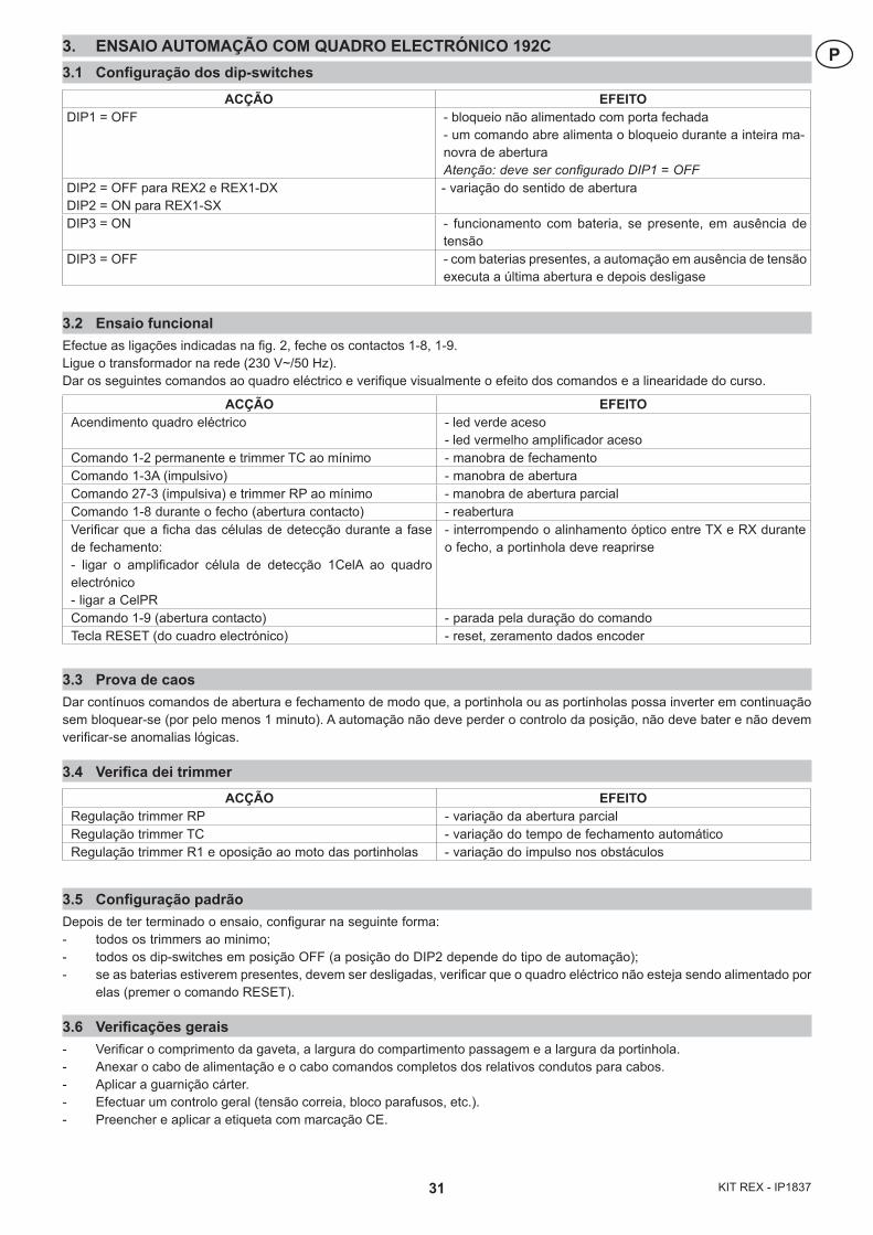
31 KIT REX - IP1837
P3. ENSAIO AUTOMAÇÃO COM QUADRO ELECTRÓNICO 192C3.1 Configuração dos dip-switches
3.2 Ensaio funcionalEfectue as ligações indicadas na fig. 2, feche os contactos 1-8, 1-9. Ligue o transformador na rede (230 V~/50 Hz). Dar os seguintes comandos ao quadro eléctrico e verifique visualmente o efeito dos comandos e a linearidade do curso.
3.3 Prova de caosDar contínuos comandos de abertura e fechamento de modo que, a portinhola ou as portinholas possa inverter em continuação sem bloquear-se (por pelo menos 1 minuto). A automação não deve perder o controlo da posição, não deve bater e não devem verificar-se anomalias lógicas.
3.4 Verifica dei trimmer
3.5 Configuração padrãoDepois de ter terminado o ensaio, configurar na seguinte forma:- todos os trimmers ao minimo;- todos os dip-switches em posição OFF (a posição do DIP2 depende do tipo de automação);- se as baterias estiverem presentes, devem ser desligadas, verificar que o quadro eléctrico não esteja sendo alimentado por
elas (premer o comando RESET).
3.6 Verificações gerais- Verificar o comprimento da gaveta, a largura do compartimento passagem e a largura da portinhola.- Anexar o cabo de alimentação e o cabo comandos completos dos relativos condutos para cabos.- Aplicar a guarnição cárter.- Efectuar um controlo geral (tensão correia, bloco parafusos, etc.).- Preencher e aplicar a etiqueta com marcação CE.
ACÇÃO EFEITOAcendimento quadro eléctrico - led verde aceso
- led vermelho amplificador acesoComando 1-2 permanente e trimmer TC ao mínimo - manobra de fechamentoComando 1-3A (impulsivo) - manobra de aberturaComando 27-3 (impulsiva) e trimmer RP ao mínimo - manobra de abertura parcialComando 1-8 durante o fecho (abertura contacto) - reaberturaVerificar que a ficha das células de detecção durante a fase de fechamento:- ligar o amplificador célula de detecção 1CelA ao quadro electrónico- ligar a CelPR
- interrompendo o alinhamento óptico entre TX e RX durante o fecho, a portinhola deve reaprirse
Comando 1-9 (abertura contacto) - parada pela duração do comandoTecla RESET (do cuadro electrónico) - reset, zeramento dados encoder
ACÇÃO EFEITODIP1 = OFF - bloqueio não alimentado com porta fechada
- um comando abre alimenta o bloqueio durante a inteira ma-novra de aberturaAtenção: deve ser configurado DIP1 = OFF
DIP2 = OFF para REX2 e REX1-DXDIP2 = ON para REX1-SX
- variação do sentido de abertura
DIP3 = ON - funcionamento com bateria, se presente, em ausência de tensão
DIP3 = OFF - com baterias presentes, a automação em ausência de tensão executa a última abertura e depois desligase
ACÇÃO EFEITORegulação trimmer RP - variação da abertura parcialRegulação trimmer TC - variação do tempo de fechamento automáticoRegulação trimmer R1 e oposição ao moto das portinholas - variação do impulso nos obstáculos
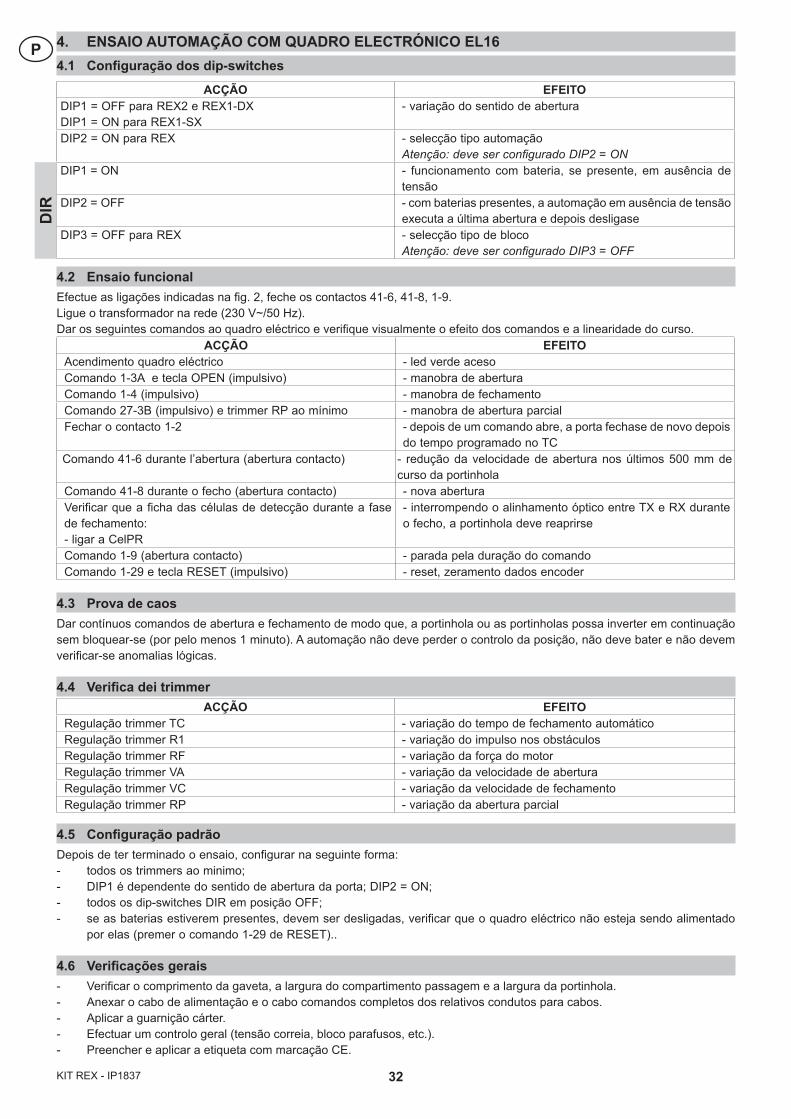
32KIT REX - IP1837
P 4. ENSAIO AUTOMAÇÃO COM QUADRO ELECTRÓNICO EL164.1 Configuração dos dip-switches
4.2 Ensaio funcionalEfectue as ligações indicadas na fig. 2, feche os contactos 41-6, 41-8, 1-9. Ligue o transformador na rede (230 V~/50 Hz). Dar os seguintes comandos ao quadro eléctrico e verifique visualmente o efeito dos comandos e a linearidade do curso.
ACÇÃO EFEITOAcendimento quadro eléctrico - led verde acesoComando 1-3A e tecla OPEN (impulsivo) - manobra de aberturaComando 1-4 (impulsivo) - manobra de fechamentoComando 27-3B (impulsivo) e trimmer RP ao mínimo - manobra de abertura parcialFechar o contacto 1-2 - depois de um comando abre, a porta fechase de novo depois
do tempo programado no TCComando 41-6 durante l’abertura (abertura contacto) - redução da velocidade de abertura nos últimos 500 mm de
curso da portinholaComando 41-8 durante o fecho (abertura contacto) - nova aberturaVerificar que a ficha das células de detecção durante a fase de fechamento:- ligar a CelPR
- interrompendo o alinhamento óptico entre TX e RX durante o fecho, a portinhola deve reaprirse
Comando 1-9 (abertura contacto) - parada pela duração do comandoComando 1-29 e tecla RESET (impulsivo) - reset, zeramento dados encoder
4.3 Prova de caosDar contínuos comandos de abertura e fechamento de modo que, a portinhola ou as portinholas possa inverter em continuação sem bloquear-se (por pelo menos 1 minuto). A automação não deve perder o controlo da posição, não deve bater e não devem verificar-se anomalias lógicas.
4.4 Verifica dei trimmer
4.5 Configuração padrãoDepois de ter terminado o ensaio, configurar na seguinte forma:- todos os trimmers ao minimo;- DIP1 é dependente do sentido de abertura da porta; DIP2 = ON;- todos os dip-switches DIR em posição OFF;- se as baterias estiverem presentes, devem ser desligadas, verificar que o quadro eléctrico não esteja sendo alimentado
por elas (premer o comando 1-29 de RESET)..
4.6 Verificações gerais- Verificar o comprimento da gaveta, a largura do compartimento passagem e a largura da portinhola.- Anexar o cabo de alimentação e o cabo comandos completos dos relativos condutos para cabos.- Aplicar a guarnição cárter.- Efectuar um controlo geral (tensão correia, bloco parafusos, etc.).- Preencher e aplicar a etiqueta com marcação CE.
ACÇÃO EFEITODIP1 = OFF para REX2 e REX1-DXDIP1 = ON para REX1-SX
- variação do sentido de abertura
DIP2 = ON para REX - selecção tipo automaçãoAtenção: deve ser configurado DIP2 = ON
DIP1 = ON - funcionamento com bateria, se presente, em ausência de tensão
DIP2 = OFF - com baterias presentes, a automação em ausência de tensão executa a última abertura e depois desligase
DIP3 = OFF para REX - selecção tipo de blocoAtenção: deve ser configurado DIP3 = OFF
DIR
ACÇÃO EFEITORegulação trimmer TC - variação do tempo de fechamento automáticoRegulação trimmer R1 - variação do impulso nos obstáculosRegulação trimmer RF - variação da força do motorRegulação trimmer VA - variação da velocidade de aberturaRegulação trimmer VC - variação da velocidade de fechamentoRegulação trimmer RP - variação da abertura parcial
33 KIT REX - IP1837
Tutti i diritti sono riservatiI dati riportati sono stati redatti e controllati con la massima cura. Tuttavia non possiamo assumerci alcuna responsabilità per eventuali errori, omissioni o approssimazioni dovute ad esigenze tecniche o grafiche.
All right reservedAll data and specifications have been drawn up and checked with the greatest care. The manufacturer cannot however take any responsibility for eventual errors, ommisions or incomplete data due to technical or illustrative purposes.
Touts droits reservésLes informations mentionnées dans ce catalogue ont été controlées avec la plus grande attention. Toutefois, nous déclinons toute responsabilité en cas d’erreurs, omissions ou approximations dépendant d’exigences techniques ou graphiques.
Alle Rechte vorbehaltenDie wiedergegebenen Daten wurden mit höchster Sorgfalt zusammengestellt und überprüft. Es kann jedoch keinerlei Verantwor-tung für eventuelle Fehler, Auslassungen oder Näherungen, die technischen oder graphischen Notwendigkeiten zuzuschreiben sind, übernommen werden.
Todos los derechos son reservadosLos datos que se indican han sido redactados y controlados con la màxima atenciòn. Sin embargo no podemos asumir ninguna responsabilidad por eventuales errores, omisiones o aproximaciones debidas a exigencias técnicas o gràficas.
Todos os direitos são reservadosOs dados indicados foram redigidos e controlados com o máximo cuidado. Contudo, não podemos assumir qualquer responsabilidade por eventuais erros, omissões ou aproximações devidas a exigências técnicas ou gráficas.
Quarto d’Altino (VE) Caronno Pertusella (VA)
Lokeren Oberursel
Palaiseau Balerna
Orlando
DITEC S.p.A.Via Mons. Banfi, 321042 Caronno P.lla (VA)ITALYTel. +39 02 963911Fax +39 02 9650314
DITEC BELGIUMLOKERENTel. +32 (0)9 356 00 51Fax +32 (0)9 356 00 52www.ditecbelgium.be
DITEC DEUTSCHLANDOBERURSELTel. +49 6171914150Fax +49 61719141555www.ditec-germany.de
DITEC FRANCEPALAISEAUTel. +33 1 64532860Fax +33 1 64532861www.ditec.fr
DITEC SVIZZERABALERNATel. +41 91 6463339Fax +41 91 6466127www.ditecswiss.ch
DITEC AMERICAORLANDO - FLORIDA - U.S.A.Tel. +1 407 8880699Fax +1 407 8882237www.ditecamerica.com
DITEC CHINASHANGHAITel. +86 21 62363861Fax +86 21 62383863www.ditec.cn