Embed Size (px)
Citation preview
GebrauchsanleitungOperation Manual
5211Motorola-Magnetartikeldecoder Motorola Digital decoder
1. Wichtige Hinweise / Important information .................................................... 22. Einleitung / Introduction .................................................................................2 – 33. Einstellungen / Settings .................................................................................3 – 44. Betrieb / Operation ........................................................................................4 – 65. Code-Tabelle / Code table .............................................................................76. Gewährleistung / Warranty ............................................................................87. Technische Daten / Technical data ................................................................ 8
MM
2
DE EN1. Wichtige HinweiseBitte lesen Sie vor der ersten Anwendung des Produktes bzw. dessen Einbau diese Bedienungs-anleitung aufmerksam durch und bewahren Sie diese auf. Sie ist Teil des Produktes.
1.1 Sicherheitshinweise
Vorsicht:
Verletzungsgefahr!Für die Montage sind Werkzeuge nötig.Stromschlaggefahr!Verwendetes Versorgungsgerät (Transformator, Netzteil) regelmäßig auf Schäden überprüfen. Bei Schäden am Versorgungsgerät dieses keinesfalls benutzen!Alle Anschluss- und Montagearbeiten nur bei abgeschalteter Betriebsspannung durchführen! Ausschließlich nach VDE/EN-gefertigte Modell-bahntransformatoren verwenden!Stromquellen unbedingt so absichern, dass es bei einem Kurzschluss nicht zum Kabelbrand kommen kann.
1.2 Das Produkt richtig verwendenDieses Produkt ist bestimmt:- Zum Einbau in Modelleisenbahnanlagen und
Dioramen.- Zum Anschluss an einen Modellbahntransfor-
mator (z. B. Art.-Nr. 5200) bzw. an eine Modell-bahnsteuerung mit zugelassener Betriebsspan-nung.
- Zum Betrieb in trockenen Räumen.Jeder darüber hinausgehende Gebrauch gilt als nicht bestimmungsgemäß. Für daraus resultierende Schäden haftet der Hersteller nicht.
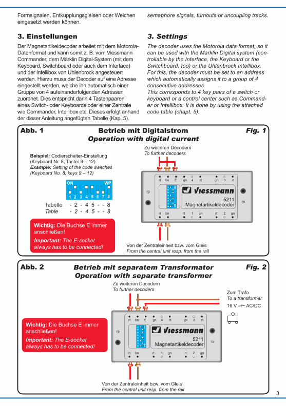
1.3 Packungsinhalt überprüfen Kontrollieren Sie den Lieferumfang auf Vollstän-digkeit:- Motorola-Magnetartikeldecoder- 2 Widerstände- 17 Stecker- 2 Schrauben- Anleitung
2. EinleitungDer digitale Magnetartikeldecoder Art.-Nr. 5211 besitzt 8 separat ansteuerbare, kurzschlusssichere Impulsausgänge, welche zum Schalten von z. B.
1. Important informationPlease read this manual completely and attentive-ly before using the product for the first time. Keep this manual. It is part of the product.
1.1 Safety instructions
Caution:
Risk of injury!For installation tools are required.Electrical hazard!Regularly examine the transformer for damage. In case of any damage, do not use the trans-former.Make sure that the power supply is switched off when you mount the device and connect the cables! Only use VDE/EN tested special model train transformers for the power supply!The power sources must be protected to prevent the risk of burning cables.
1.2 Using the product for its correct purpose
This model is intended:- For installation in model railroad train and
dioramas.- For connection to an authorized model train
transformer (e. g. item-No. 5200) or a model train control module with authorized operating voltage.
- For operation in dry rooms only.Using the product for any other purpose is not ap-proved and is considered incorrect. The manufac-turer is not responsible for any damage resulting from the improper use of this product.
1.3 Checking the package contents
Check the contents of the package for complete-ness:- Motorola Digital decoder- 2 resistors- 17 plugs- 2 screws- Manual
2. IntroductionThe digital decoder item-No. 5211 has 8 sepa-rately controllable, short-circuit-proof impulse outputs which can be used for switching e. g.
3
ViessmannMagnetartikeldecoder
5211
rt bn rt 1 gn rt 2 gn
ON1
23
45
67
8
WP
Viessmann5211
Magnetartikeldecoder
rt bn E gn 4 rt gn 3 rt
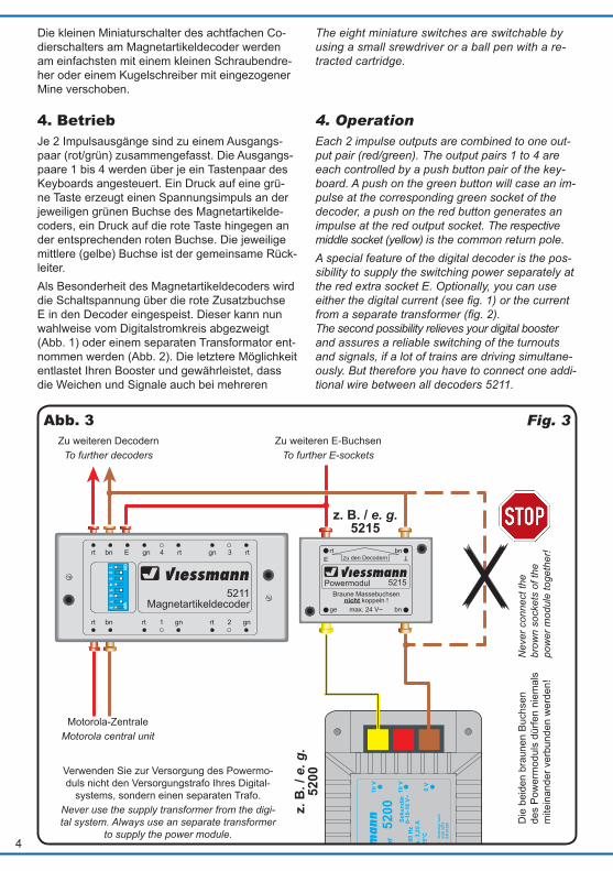
Tabelle - 2 - 4 5 - - 8Table - 2 - 4 5 - - 8
Beispiel: Codierschalter-Einstellung (Keyboard Nr. 8, Taster 9 – 12)Example: Setting of the code switches (Keyboard No. 8, keys 9 – 12)
Betrieb mit Digitalstrom Operation with digital current
Formsignalen, Entkupplungsgleisen oder Weichen eingesetzt werden können.
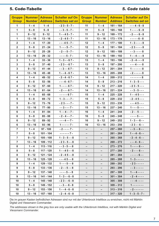
3. EinstellungenDer Magnetartikeldecoder arbeitet mit dem Motorola- Datenformat und kann somit z. B. vom Viessmann Commander, dem Märklin Digital-System (mit dem Keyboard, Switchboard oder auch dem Interface) und der Intellibox von Uhlenbrock angesteuert werden. Hierzu muss der Decoder auf eine Adresse eingestellt werden, welche ihn automatisch einer Gruppe von 4 aufeinanderfolgenden Adressen zuordnet. Dies entspricht dann 4 Tastenpaaren eines Switch- oder Keyboards oder einer Zentrale wie Commander, Intellibox etc. Dieses erfolgt anhand der dieser Anleitung angefügten Tabelle (Kap. 5).
semaphore signals, turnouts or uncoupling tracks.
3. SettingsThe decoder uses the Motorola data format, so it can be used with the Märklin Digital system (con-trollable by the Interface, the Keyboard or the Switchboard, too) or the Uhlenbrock Intellibox. For this, the decoder must be set to an address which automatically assigns it to a group of 4 consecutive addresses. This corresponds to 4 key pairs of a switch or keyboard or a control center such as Command-er or Intellibox. It is done by using the attached code table (chapt. 5).
Fig. 1Abb. 1
Von der Zentraleinheit bzw. vom GleisFrom the central unit resp. from the rail
Zu weiteren DecodernTo further decoders
Wichtig: Die Buchse E immer anschließen!Important: The E-socket always has to be connected!
rt bn rt 1 gn rt 2 gn
ON1
23
45
67
8
WP
Viessmann5211
Magnetartikeldecoder
rt bn E gn 4 rt gn 3 rt
Fig. 2Abb. 2
Zu weiteren DecodernTo further decoders Zum Trafo
To a transformer16 V =/~ AC/DC
Von der Zentraleinheit bzw. vom GleisFrom the central unit resp. from the rail
Betrieb mit separatem Transformator Operation with separate transformer
Wichtig: Die Buchse E immer anschließen!Important: The E-socket always has to be connected!
4
Die kleinen Miniaturschalter des achtfachen Co-dierschalters am Magnetartikeldecoder werden am einfachsten mit einem kleinen Schraubendre-her oder einem Kugelschreiber mit eingezogener Mine verschoben.
4. BetriebJe 2 Impulsausgänge sind zu einem Ausgangs-paar (rot/grün) zusammengefasst. Die Ausgangs-paare 1 bis 4 werden über je ein Tastenpaar des Keyboards angesteuert. Ein Druck auf eine grü-ne Taste erzeugt einen Spannungsimpuls an der jeweiligen grünen Buchse des Magnetartikelde-coders, ein Druck auf die rote Taste hingegen an der entsprechenden roten Buchse. Die jeweilige mittlere (gelbe) Buchse ist der gemeinsame Rück-leiter.Als Besonderheit des Magnetartikeldecoders wird die Schaltspannung über die rote Zusatzbuchse E in den Decoder eingespeist. Dieser kann nun wahlweise vom Digitalstromkreis abgezweigt (Abb. 1) oder einem separaten Transformator ent-nommen werden (Abb. 2). Die letztere Möglichkeit entlastet Ihren Booster und gewährleistet, dass die Weichen und Signale auch bei mehreren
viessmannPowermodul 5215
T
E
ge bn
Braune Massebuchsennicht koppeln !
max. 24 V~
rt bnzu den Decodern
Seku
ndär
0-10
-16
V~
16 V
Prim
är23
0 V~
Gef
ertig
t nac
hVD
E 05
70EN
615
58
Lich
ttran
sfor
mat
or52
00
Nur
für t
rock
ene
Räu
me
Prim
är23
0 V
50
- 60
Hz
Seku
ndär
max
. 3,2
5 A
52 V
Ata
25°
CIP
40
10 V
0 V
rt bn rt 1 gn rt 2 gn
ON1
23
45
67
8
WP
Viessmann5211
Magnetartikeldecoder
rt bn E gn 4 rt gn 3 rt
Fig. 3Abb. 3Zu weiteren Decodern
To further decodersZu weiteren E-Buchsen
To further E-sockets
Die
bei
den
brau
nen
Buch
sen
des
Pow
erm
odul
s dü
rfen
niem
als
mite
inan
der v
erbu
nden
wer
den!
Nev
er c
onne
ct th
e br
own
sock
ets
of th
e po
wer
mod
ule
toge
ther
!
Motorola-ZentraleMotorola central unit
Verwenden Sie zur Versorgung des Powermo-duls nicht den Versorgungstrafo Ihres Digital-
systems, sondern einen separaten Trafo.Never use the supply transformer from the digi-tal system. Always use an separate transformer
to supply the power module.
The eight miniature switches are switchable by using a small srewdriver or a ball pen with a re-tracted cartridge.
4. OperationEach 2 impulse outputs are combined to one out-put pair (red/green). The output pairs 1 to 4 are each controlled by a push button pair of the key-board. A push on the green button will case an im-pulse at the corresponding green socket of the decoder, a push on the red button generates an impulse at the red output socket. The respective middle socket (yellow) is the common return pole.A special feature of the digital decoder is the pos-sibility to supply the switching power separately at the red extra socket E. Optionally, you can use either the digital current (see fig. 1) or the current from a separate transformer (fig. 2). The second possibility relieves your digital booster and assures a reliable switching of the turnouts and signals, if a lot of trains are driving simultane-ously. But therefore you have to connect one addi-tional wire between all decoders 5211.
z. B. / e. g. 5215
z. B
. / e
. g.
5200

5
Minitrix-WeicheMinitrix turnout
5,6 Ohm1 Watt
gleichzeitig fahrenden Zügen noch sicher schal-ten. Hierzu ist ein separates Kabel notwendig, welches die E-Buchsen aller Magnetartikelde-coder 5211 miteinander verbindet. Zur Erzielung der optimalen Schaltleistung ist es empfehlens-wert, die Versorgung der E-Buchse über das Pow-ermodul Art.-Nr. 5215 vorzunehmen (Abb. 3).
4.1 Betrieb mit der IntelliboxDies gilt auch bei Benutzung der Intellibox. Hier-bei kann es aber zu Problemen mit Minitrix-Wei-chenantrieben kommen. Diese haben im Schalt-moment eine Stromaufnahme von 2,2 A. Dann spricht die Überlastsicherung des 5211 an, um die Endstufen vor Überhitzung zu bewahren. Zunächst schließen Sie die E-Buchse jedes De-coders an einem Powermodul Art.-Nr. 5215 an. Es reicht ein Powermodul für alle angeschlosse-nen Magnetartikeldecoder 5211 aus. Dieses Pow-ermodul versorgen Sie mit 16 Volt Wechselspan-nung, wie sie z. B. vom Lichttransformator Art.-Nr. 5200 geliefert wird. In die weiße Zuleitung (gemeinsamer Pol beider Antriebsspulen) jeder Minitrixweiche, welche am gelben (mittleren) Pol der Ausgangsbuchsen-Drei-ergruppen des Magnetartikeldecoders 5211 an-geschlossen wird, schalten Sie einen Widerstand von 5,6 Ohm und einer Leistung von 1 Watt (Abb. 4). Diesen erhalten Sie im Elektronikfachhandel.
Achtung!Bei separater Schaltspannungseinspeisung (Abb. 2) die rote Leitung E und das rote Kabel des Digi-talstromkreises nicht zusammenschalten! Ledig-lich die Masseleitungen (braun) werden gekop-pelt. Allerdings muss die rote Buchse E immer entweder nach Abb. 1 oder Abb. 2 angeschlos-sen sein, da ansonsten vom Decoder keine Span-nungsimpulse an dessen Ausgängen erzeugt wer-den können.
4.2 Gemeinsamer Betrieb von Art.-Nr. 5280 und Art.-Nr. 5211Der Multiprotokoll Schalt- und Weichendecoder Art.-Nr. 5280 ist die vielseitige Alternative zu Art.-Nr. 5211. Der Decoder ist ein Multiprotokoll-De-coder für das DCC- und Märklin-Motorola-Format. Er ist als Weichendecoder für 4 Weichen mit Dop-pelspulen ausgelegt und steuert zusätzlich 2 Ser-vos an. Er besitzt 4 Ausgangspaare, die auch für Sonderfunktionen konfiguriert werden können.
Fig. 4Abb. 4
To achieve the optimum of switching power you should use the Viessmann power module item-No. 5215 to supply the E-socket (fig. 3).
4.1 Operation with Intellibox
Even by operation with Intellibox. However, it can lead to problems with Minitrix point drives. These have a current consumption of 2,2 A. Then the overload protection of item-No. 5211 is activated, in order to protect the output stages from over-heating.First, connect the E-socket of each decoder to a power module, item-No. 5215. One power module is sufficient for all connected digital decoders, item-No. 5211. Supply 16 V AC voltage to this power module. As for example, supplied from the light transformer, item-No. 5200. Switch a resistor of 5,6 Ohm and a power of 1 Watt into the white line (common pole of both drive coils) of all Minitrix turnouts, which is connected to the yellow (middle) pole of the output socket triplets of the digital decoder (fig. 4), which are offered by electronic specialist shops.
Attention!If you use a separate transformer (fig. 2) do not connect the red wire E to the red ground cables of the digital current circuit. Only the ground wire (brown) have to be coupled. But the red socket must always be connected like it is shown in fig. 1 and 2. Otherwise, no voltage pulses can be gener-ated by the decoder at the outputs.
4.2 Common operation of item-No. 5280 and item-No. 5211
The multi protocol switching and turnout decoder item-No. 5280 is the multifunctional alternative to item-No. 5211. The decoder is a multiprotocol decoder for the DCC and the Märklin Motorola for-mat. It is designed as a turnout decoder for 4 turn-outs with double coils and it controls also 2 servos. It has 4 output pairs, which can also be configured for special functions.
6
E
rt bn rt 1 gn rt 2 gn
ON1
23
45
67
8
WP
Viessmann5211
Magnetartikeldecoder
rt bn E gn 4 rt gn 3 rt
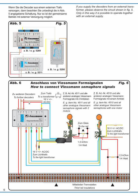
Fig. 6Abb. 6 Anschluss von Viessmann Formsignalen How to connect Viessmann semaphore signals
Zu weiteren DecodernTo further decoders
Z. B. Art.-Nr. 4511 und alle anderen analogen Viessmann Formsignale mit 2 AntriebenE. g. item-No. 4511 and all other analogue Viessmann semaphore signals with 2 motors
Zum TrafoTo a transformer
Zum GleisTo the rail
1,5 kOhm1/4 Watt
Z. B. Art.-Nr. 4510 und alle anderen analogen Viessmann Formsignale mit einem AntriebE. g. item-No. 4510 and all other analogue Viessmann semaphores with one motor
1,5 kOhm1/4 Watt
16 V =/~ AC/DC
Mittelleiter-TrennstellenThird rail insulations
16 V =/~ AC/DC Zum Lichttrafo To the light transformer
16 V =/~ AC/DC Zum Lichttrafo To the light transformer
ViessmannMagnetartikeldecoder
5211
Seku
ndär
0-10
-16
V~
16 V
Prim
är23
0 V~
Gef
ertig
t nac
hVD
E 05
70EN
615
58
Lich
ttran
sfor
mat
or52
00
Nur
für t
rock
ene
Räu
me
Prim
är23
0 V
50
- 60
Hz
Seku
ndär
max
. 3,2
5 A
52 V
Ata
25°
CIP
40
10 V
0 V
Fig. 5Abb. 5
Wenn Sie die Decoder aus einem externen Trafo versorgen, dann beachten Sie unbedingt die in Abb. 5 angegebene Schaltung. Nur so ist der gemeinsame Betrieb mit externer Versorgung möglich.
z. B. / e. g. 5280
z. B. / e. g. 5211z. B. / e. g. 5200
If you supply the decoders from an external trans-former, please observe the circuit shown in fig. 5. Only in this way it is possible to operate together with an external supply.
7
Gruppe Group
Nummer Number
Adresse Address
Schalter auf On Switches set on
Gruppe Group
Nummer Number
Adresse Address
Schalter auf On Switches set on
1 1 – 4 1 - 4 - 2 3 - 5 - 7 - 11 1 – 4 161 – 164 - - - 4 - 6 - 81 5 – 8 5 - 8 - - 3 - 5 - 7 - 11 5 – 8 165 – 168 1 - - - - 6 - 81 9 – 12 9 - 12 1 - - 4 5 - 7 - 11 9 – 12 169 – 172 - 2 - - - 6 - 81 13 – 16 13 - 16 - 2 - 4 5 - 7 - 11 13 – 16 173 – 176 - - - - - 6 - 82 1 – 4 17 - 20 - - - 4 5 - 7 - 12 1 – 4 177 – 180 1 - 3 - - - - 82 5 – 8 21 - 24 1 - - - 5 - 7 - 12 5 – 8 181 – 184 - 2 3 - - - - 82 9 – 12 25 - 28 - 2 - - 5 - 7 - 12 9 – 12 185 – 188 - - 3 - - - - 82 13 – 16 29 - 32 - - - - 5 - 7 - 12 13 – 16 189 – 192 1 - - 4 - - - 83 1 – 4 33 - 36 1 - 3 - - 6 7 - 13 1 – 4 193 – 196 - 2 - 4 - - - 83 5 – 8 37 - 40 - 2 3 - - 6 7 - 13 5 – 8 197 – 200 - - - 4 - - - 83 9 – 12 41 - 44 - - 3 - - 6 7 - 13 9 – 12 201 – 204 1 - - - - - - 83 13 – 16 45 - 48 1 - - 4 - 6 7 - 13 13 – 16 205 – 208 - 2 - - - - - 84 1 – 4 49 - 52 - 2 - 4 - 6 7 - 14 1 – 4 209 – 212 - - - - - - - 84 5 – 8 53 - 56 - - - 4 - 6 7 - 14 5 – 8 213 – 216 1 - 3 - 5 - - -4 9 – 12 57 - 60 1 - - - - 6 7 - 14 9 – 12 217 – 220 - 2 3 - 5 - - -4 13 – 16 61 - 64 - 2 - - - 6 7 - 14 13 – 16 221 – 224 - - 3 - 5 - - -5 1 – 4 65 - 68 - - - - - 6 7 - 15 1 – 4 225 – 228 1 - - 4 5 - - -5 5 – 8 69 - 72 1 - 3 - - - 7 - 15 5 – 8 229 – 232 - 2 - 4 5 - - -5 9 – 12 73 - 76 - 2 3 - - - 7 - 15 9 – 12 233 – 236 - - - 4 5 - - -5 13 – 16 77 - 80 - - 3 - - - 7 - 15 13 – 16 237 – 240 1 - - - 5 - - -6 1 – 4 81 - 84 1 - - 4 - - 7 - 16 1 – 4 241 – 244 - 2 - - 5 - - -6 5 – 8 85 - 88 - 2 - 4 - - 7 - 16 5 – 8 245 – 248 - - - - 5 - - -6 9 – 12 89 - 92 - - - 4 - - 7 - 16 9 – 12 249 – 252 1 - 3 - - 6 - -6 13 – 16 93 - 96 1 - - - - - 7 - 16 13 – 16 253 – 256 - 2 3 - - 6 - -7 1 – 4 97 - 100 - 2 - - - - 7 - – – 257 – 260 - - 3 - - 6 - -7 5 – 8 101 - 104 - - - - - - 7 - – – 261 – 264 1 - - 4 - 6 - -7 9 – 12 105 - 108 1 - 3 - 5 - - 8 – – 265 – 268 - 2 - 4 - 6 - -7 13 – 16 109 - 112 - 2 3 - 5 - - 8 – – 269 – 272 - - - 4 - 6 - -8 1 – 4 113 - 116 - - 3 - 5 - - 8 – – 273 – 276 1 - - - - 6 - -8 5 – 8 117 - 120 1 - - 4 5 - - 8 – – 277 – 280 - 2 - - - 6 - -8 9 – 12 121 - 124 - 2 - 4 5 - - 8 – – 281 – 284 - - - - - 6 - -8 13 – 16 125 - 128 - - - 4 5 - - 8 – – 285 – 288 1 - 3 - - - - -9 1 – 4 129 - 132 1 - - - 5 - - 8 – – 289 – 292 - 2 3 - - - - -9 5 – 8 133 - 136 - 2 - - 5 - - 8 – – 293 – 296 - - 3 - - - - -9 9 – 12 137 - 140 - - - - 5 - - 8 – – 297 – 300 1 - - 4 - - - -9 13 – 16 141 - 144 1 - 3 - - 6 - 8 – – 301 – 304 - 2 - 4 - - - -
10 1 – 4 145 - 148 - 2 3 - - 6 - 8 – – 305 – 308 - - - 4 - - - -10 5 – 8 149 - 152 - - 3 - - 6 - 8 – – 309 – 312 1 - - - - - - -10 9 – 12 153 - 156 1 - - 4 - 6 - 8 – – 313 – 316 - 2 - - - - - -10 13 – 16 157 - 160 - 2 - 4 - 6 - 8 – – 317 – 320 1 - 3 - 5 - 7 -
Die im grauen Kasten befindlichen Adressen sind nur mit der Uhlenbrock Intellibox zu erreichen, nicht mit Märklin Digital und Viessmann Commander.The addresses shown in the grey box are only usable with the Uhlenbrock Intellibox, not with Märklin Digital and Viessmann Commander.
5. Code-Tabelle 5. Code table
Made in Europe
Modellbauartikel, kein Spielzeug! Nicht geeignet für Kinder unter 14 Jahren! Anleitung aufbewahren!
Model building item, not a toy! Not suitable for children under the age of 14 years! Keep these instructions!
Ce n’est pas un jouet. Ne convient pas aux enfants de moins de 14 ans ! C’est un produit décor! Conservez cette notice d’instructions!
Não é um brinquedo!Não aconselhável para menores de 14 anos. Conservar a embalagem.
Modelbouwartikel, geen speelgoed! Niet geschikt voor kinderen onder 14 jaar! Gebruiksaanwijzing bewaren!
Articolo di modellismo, non è un giocattolo! Non adatto a bambini al di sotto dei 14 anni! Conservare instruzioni per l’uso!
Artículo para modelismo ¡No es un juguete! No recomendado para menores de 14 años! Conserva las instrucciones de servicio!
DE
EN
FR
NL
IT
ES
PT
Modelltechnik GmbHBahnhofstraße 2aD - 35116 Hatzfeld-Reddighausenwww.viessmann-modell.de8
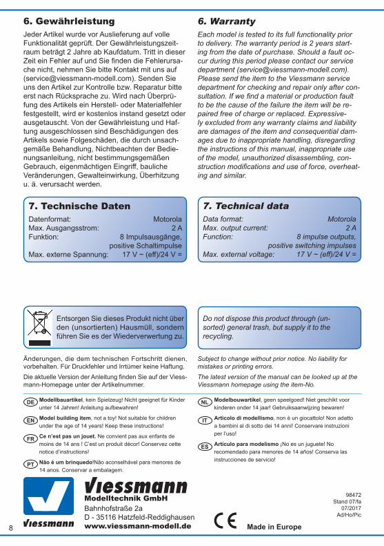
6. GewährleistungJeder Artikel wurde vor Auslieferung auf volle Funktionalität geprüft. Der Gewährleistungszeit-raum beträgt 2 Jahre ab Kaufdatum. Tritt in dieser Zeit ein Fehler auf und Sie finden die Fehlerursa-che nicht, nehmen Sie bitte Kontakt mit uns auf ([email protected]). Senden Sie uns den Artikel zur Kontrolle bzw. Reparatur bitte erst nach Rücksprache zu. Wird nach Überprü-fung des Artikels ein Herstell- oder Materialfehler festgestellt, wird er kostenlos instand gesetzt oder ausgetauscht. Von der Gewährleistung und Haf-tung ausgeschlossen sind Beschädigungen des Artikels sowie Folgeschäden, die durch unsach-gemäße Behandlung, Nichtbeachten der Bedie-nungsanleitung, nicht bestimmungsgemäßen Gebrauch, eigenmächtigen Eingriff, bauliche Veränderungen, Gewalteinwirkung, Überhitzung u. ä. verursacht werden.
6. WarrantyEach model is tested to its full functionality prior to delivery. The warranty period is 2 years start-ing from the date of purchase. Should a fault oc-cur during this period please contact our service department ([email protected]). Please send the item to the Viessmann service department for checking and repair only after con-sultation. If we find a material or production fault to be the cause of the failure the item will be re-paired free of charge or replaced. Expressive-ly excluded from any warranty claims and liability are damages of the item and consequential dam-ages due to inappropriate handling, disregarding the instructions of this manual, inappropriate use of the model, unauthorized disassembling, con-struction modifications and use of force, overheat-ing and similar.
98472 Stand 07/fa
07/2017Ad/Ho/Pic
7. Technical dataData format: Motorola Max. output current: 2 A Function: 8 impulse outputs, positive switching impulses Max. external voltage: 17 V ~ (eff)/24 V =
7. Technische DatenDatenformat: Motorola Max. Ausgangsstrom: 2 A Funktion: 8 Impulsausgänge, positive Schaltimpulse Max. externe Spannung: 17 V ~ (eff)/24 V =
Entsorgen Sie dieses Produkt nicht über den (unsortierten) Hausmüll, sondern führen Sie es der Wiederverwertung zu.
Do not dispose this product through (un-sorted) general trash, but supply it to the recycling.
Änderungen, die dem technischen Fortschritt dienen, vorbehalten. Für Druckfehler und Irrtümer keine Haftung.Die aktuelle Version der Anleitung finden Sie auf der Viess-mann-Homepage unter der Artikelnummer.
Subject to change without prior notice. No liability for mistakes or printing errors.The latest version of the manual can be looked up at the Viessmann homepage using the item-No.