Embed Size (px)
Citation preview
EN 16798-2 TR:2014 (E)
1
CEN TC156
Date: 2014-11-30
EN 16798-2 TR Draft 8
Fehler! Verweisquelle konnte nicht gefunden werden./TC Fehler! Verweisquelle konnte nicht gefunden werden.WG19-N89
Secretariat: Fehler! Verweisquelle konnte nicht gefunden werden.
Guideline for using indoor environmental input parameters for the design and assessment of energy performance of
buildings.
EN 16798-2 TR:2014 (E)
2
Contents Page
Guideline for using indoor environmental input parameters for the design and assessment of energy performance of buildings.............................................................................. 1
1 Scope...................................................................................................................................................... 5
2 Normative references ........................................................................................................................... 6
3 Terms and definitions........................................................................................................................... 6
4 Symbols and abbreviations ................................................................................................................. 6
5 Interactions with other standards and use of categories................................................................. 7
6 How to establish design input criteria for dimensioning of buildings, heating, cooling, ventilation and lighting systems. ....................................................................................... 10
6.1 Thermal environment.......................................................................................................................... 106.1.1 Mechanically heated and/or cooled buildings ................................................................................. 106.1.2 Buildings without mechanical cooling ............................................................................................. 126.1.3 Increased air velocity.......................................................................................................................... 136.2 Design for Indoor air quality (ventilation rates)............................................................................... 146.2.1 General................................................................................................................................................. 146.2.3 Non-residential buildings................................................................................................................... 156.2.4 Residential buildings.......................................................................................................................... 166.2.6 Filtration and air cleaning .................................................................................................................. 176.3 Humidity............................................................................................................................................... 176.4 Lighting ................................................................................................................................................ 186.4.1 Non residential buildings ................................................................................................................... 186.4.2 Residential buildings.......................................................................................................................... 186.5 Noise..................................................................................................................................................... 18
7 Indoor environment parameters for energy calculation ................................................................. 197.1 Thermal environment.......................................................................................................................... 197.1.1 Seasonal calculations......................................................................................................................... 197.1.2 Hourly calculations or dynamic building simulation ...................................................................... 197.2 Indoor air quality and ventilation ...................................................................................................... 197.2.1 General................................................................................................................................................. 197.2.2 Non-residential buildings................................................................................................................... 197.2.3 Residential buildings.......................................................................................................................... 207.3 Humidity............................................................................................................................................... 207.4 Lighting ................................................................................................................................................ 20
8 Evaluation of the indoor environment and long term indicators................................................... 208.1 Design indicators ................................................................................................................................ 208.2 Calculated indicators of indoor environment .................................................................................. 208.2.1 Simple indicator .................................................................................................................................. 218.2.2 Hourly criteria...................................................................................................................................... 218.2.3 Degree hours criteria.......................................................................................................................... 218.2.4 Overall thermal comfort criteria (weighted PMV criteria) ............................................................... 218.3 Measured indicators ........................................................................................................................... 218.3.1 Thermal environment.......................................................................................................................... 218.3.2 Indoor air quality and ventilation ...................................................................................................... 228.3.3 Lighting ................................................................................................................................................ 228.3.4 Noise..................................................................................................................................................... 228.4 Subjective evaluations ....................................................................................................................... 23
9 Inspections and measurement of the indoor environment in existing buildings ........................ 23
EN 16798-2 TR:2014 (E)
3
9.1 Measurements ..................................................................................................................................... 239.1.1 Thermal environment.......................................................................................................................... 239.1.2 Indoor air quality ................................................................................................................................. 249.1.3 Indoor Light quality measurements based on illuminance. ........................................................... 25
10 Classification and certification of the indoor environment. ........................................................... 2510.1 Detailed classification and certification ........................................................................................... 2510.2 Recommended overall evaluation of the indoor environment and certification.......................... 25
Annex A (informative) Information about national Annexes......................................................................... 26
Annex B 1 (informative) Recommended criteria for the thermal environment ........................................... 27B1.1 Recommended categories for design of mechanically heated and cooled
buildings .............................................................................................................................................. 27B1.3 Recommended indoor temperatures for energy calculations............................................................ 33
ANNEX B2 (informative) Basis for the criteria for indoor air quality and ventilation rates ....................... 35B2.1 General ..................................................................................................................................................... 35B2.2 - Method based on perceived air quality............................................................................................... 35B.2.3 - Method using limit values of gas concentration............................................................................... 43B2.4 Design ventilation rates in residential buildings ............................................................................... 44B 2.4.2 Principle of air flow rate calculations................................................................................................ 45B2.4.3 Basic information on mechanical and natural residential ventilation systems............................. 46B2.7 Indoor air quality in existing residential buildings .............................................................................. 56B2.8 Recommended criteria for dimensioning of humidification and de-humidification .................... 56B2.9 Recommended ventilation during non-occupied hours. ................................................................ 57
ANNEX B3 (informative) Example on how to define low and very low polluting buildings...................... 58
Annex B4 (informative) Examples of criteria for lighting ............................................................................. 61
ANNEX B5 (informative) Indoor system noise criteria of some spaces and buildings............................ 63
ANNEX C (informative) Long term evaluation of the general thermal comfort conditions..................... 64
ANNEX D (informative) Recommended criteria for acceptable deviations............................................... 67D.1 Building Category ............................................................................................................................... 67D.2 Length of deviation ............................................................................................................................. 67
ANNEX E (informative) Methodologies for subjective evaluations ................................................................... 72
ANNEX F (informative) Examples of classification and certification of the indoor environment......................................................................................................................................... 74
F.1 The design criteria used............................................................................................................................ 74F.2 Whole year computer simulations of the indoor environment and energy performance................. 75F.3 Long term measurement of selected parameters for the indoor environment ................................... 75F.4 Subjective responses from occupants.................................................................................................... 75
ANNEX G (informative) Recommended criteria for personalized systems. ............................................. 77
ANNEX B11 (informative) Recommended methods for substitute ventilation air by air cleaning................................................................................................................................................ 79
ANNEX I (informative) WHO criteria for health in the indoor environment............................................... 81

EN 16798-2 TR:2014 (E)
4
Foreword
This document EN 16798-2 TR has been prepared by Technical Committee CEN/TC 156“Ventilation for Buildings”, the secretariat of which is held by BSI.
This document is currently a draft for the working group.
This document has been prepared under a mandate 480 given to CEN by the European Commission and the European Free Trade Association, and supports essential requirements of EU Directive 2002/91/EC and recast.
CEN members are the national standards bodies of Austria, Belgium, Denmark, Finland, France, Germany, Greece, Iceland, Ireland, Italy, Luxembourg, Netherlands, Norway, Portugal, Spain, Sweden, Switzerland and United Kingdom. plus, plus, plus, plus++++++++++
EN 16798-2 TR:2014 (E)
5
Introduction
Energy consumption of buildings depends significantly on the criteria used for the indoor environment (temperature, ventilation and lighting) and building (including systems) design and operation. Indoor environment also affects health, productivity and comfort of the occupants. Recent studies have shown that costs of poor indoor environment for the employer, the building owner and for society, as a whole are often considerable higher than the cost of the energy used in the same building. It has also been shown that good indoor environmental quality can improve overall work and learning performance and reduce absenteeism. In addition uncomfortable occupants are likely to take actions to make themselves comfortable which may have energy implications. There is therefore a need for specifying criteria for the indoor environment for design and energy calculations for buildings
The present Technical Report is a guide to prEN16798-1 and should help the user in application of the standard and give additional background information. Besides this technical report describes and recommend additional topics related to the requirements in the EPBD and new possibilities to improve the indoor environmental quality and reduce energy consumption of buildings like personalized systems, air cleaning technologies, consideration of adapted persons etc.. There exist other national and international standards, and technical reports, which specify criteria for thermal comfort and indoor air quality (EN ISO 7730). These documents do specify different types and categories of criteria, which may have a significant influence on the energy demand. For the thermal environment criteria for the heating season (cold/winter) and cooling season (warm/summer) are listed. These criteria are, however, mainly for dimensioning of building, heating, cooling and ventilation systems. They may not be used directly for energy calculations and year-round evaluation of the indoor thermal environment.
The present technical report explains how design criteria can be established and used fordimensioning of systems. It explains how to establish and define the main parameters to be used as input for building energy calculation and long term evaluation of the indoor environment. This technical report also describes how gas phase air cleaning in the future may improve the indoor air quality and partly substitute for outside air. Finally this technical report will identify parameters to be used for monitoring and displaying of the indoor environment as recommended in the Energy Performance of Buildings Directive.
Different categories of criteria may be used depending on type of building, type of occupants, type of climate and national differences. The report explains how these different categories of indoor environment can be individually selected as national criteria, be used in project agreement for design criteria and for displaying the yearly building performance in relation to indoor environmental quality. The designer may also define other categories using the principles from the standard prEN16798-1and this technical report.
1 Scope
This European Technical Report deals with the indoor environmental parameters for thermal environment, indoor air quality, lighting and acoustic.
The technical report explains how to use prEN16798-1 for specifying indoor environmental input parameters for building system design and energy performance calculations.
EN 16798-2 TR:2014 (E)
6
The technical report specifies methods for long term evaluation of the indoor environment obtained as a result of calculations or measurements.
The report specifies criteria for measurements which can be used if required to measure compliance by inspection.
The report identifies parameters to be used by monitoring and displaying the indoor environment in existing buildings.
This report is applicable where the criteria for indoor environment are set by human occupancy and where the production or process does not have a major impact on indoor environment.
The report explains how different categories of criteria for the indoor environment can be used.
2 Normative references
The references in PREN16798-1 are also applicable in this Technical Report. Additional references are listed in the bibliography..
3 Terms and definitions
For the general purposes of this European Technical Report, the terms and definitions given in PREN16798-1, EN 12792, EN ISO 13731 and EN 12464, EN12665 and EN15603 apply.
Additional terms and definitions are listed below
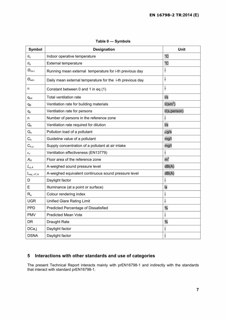
4 Symbols and abbreviations
The symbols and abbreviations used in this document are listed in Table 0.
EN 16798-2 TR:2014 (E)
7
Table 0 — Symbols
Symbol Designation Unit
o Indoor operative temperature °C
e External temperature oC
Θrm-i Running mean external temperature for i-th previous day -
Θed-i Daily mean external temperature for the i-th previous day -
Constant between 0 and 1 in eq (1) -
qtot Total ventilation rate l/s
qB Ventilation rate for building materials l/(sm2)
qp Ventilation rate for persons l/(s,person)
n Number of persons in the reference zone -
Qh Ventilation rate required for dilution l/s
Gh Pollution load of a pollutant g/s
Ch Guideline value of a pollutant mg/l
Ch,o Supply concentration of a pollutant at air intake mg/l
v Ventilation effectiveness (EN13779) -
AR Floor area of the reference zone m2
Lp,A A-weighed sound pressure level dB(A)
Leq, nT,A A-weighed equivalent continuous sound pressure level dB(A)
D Daylight factor -
E Illuminance (at a point or surface) lx
Ra Colour rendering index -
UGR Unified Glare Rating Limit -
PPD Predicted Percentage of Dissatisfied %
PMV Predicted Mean Vote -
DR Draught Rate %
DCa,j Daylight factor -
DSNA Daylight factor -
5 Interactions with other standards and use of categories
The present Technical Report interacts mainly with prEN16798-1 and indirectly with the standards that interact with standard prEN16798-1.
EN 16798-2 TR:2014 (E)
8
The technical report explains how the indoor environmental criteria in prEN16798-1 can be used for the design of building and HVAC systems. The thermal criteria (design indoor temperature in winter, design indoor temperature in summer) are used as input for heating (EN12831) and cooling load (EN 15243) calculations and sizing of the installed systems. Ventilation rates are used for sizing ventilation systems, and lighting levels for design of lighting system including the use of day lighting (EN12464-1). The design values for sizing the building services are needed to fulfil the requirements in the EPBD referring to possible negative effect of indoor environment and to give advice in respect ofimprovement of the energy efficiency of existing buildings as well as of the heating and cooling of buildings.
The technical report explains how values for the indoor environment (temperature, ventilation, lighting) are used as input to the calculation of the energy demand (building energy demand, EN ISO 13790, EN 15255, EN 15265, EN15193.
Output from measured indoor environmental parameters in existing buildings (EN 15203, temperature, indoor air quality, ventilation rates) will enable the evaluation of overall annual performance and can be used to display the indoor environmental factors together with date for the energy performance.
Output from room temperature calculations (EN ISO 13791, EN ISO 13792) and yearly dynamic building simulations will enable evaluation of the annual performance of buildings at the design stage.
The technical report describes methods for measurement of the indoor environment and for treating measured data related to the inspection of HVAC systems (EN 15240, EN 15239, EN 15378). This information is necessary to give advice related to the heating loads and system and air conditioning load and system of a building.

EN 16798-2 TR:2014 (E)
9
Figure 1 - Interaction with other standards or guidelines (update with new numbers)
The technical report will provide a method for categorisation of indoor environment (section 10). This method is necessary to integrate complex indoor environment information to simple classification for a possible indoor environment certificate.
Recommended input values are given for each of the different categories as shown in table 1. Thesecategories can be used in different ways. First and foremost they can be used to establish different levels of criteria for the design of buildings and building services. Different countries may want to standardise one category for design. The consultant and client of a building project can use the categories to agree on a specific design level. The intension is not that a building must be operated strictly in one class the whole year round. Instead the categories can be used to describe the yearly indoor environmental performance of a building by showing the distribution of the parameters in the different categories. It can then on national level or in a design/operation contract be specified how much of the time the categories may be exceeded. This is shown in this report with some examples.
Table 1 - Description of the applicability of the categories used
Category Explanation
IHigh level of expectation and also recommended for spaces occupied by very sensitive and fragile persons with special requirements like some disabilities, sick, very young children and elderly persons, to increase accessibility.
EN 16798-2 TR:2014 (E)
10
II Normal level of expectation
III An acceptable, moderate level of expectation
IVLow level of expectation. This category should only be accepted for a limited part of the year
Even if a building is designed for category III it may still be operated a greater part of the year in Category I or II.
It can be argued that selecting a higher category may increase the energy consumption. The energy requirement is however regulated by national building codes and cannot be exceeded. The challenge is then for the designer/operator of the building to obtain a high level of indoor environmental qualitywithin the required energy criteria.
6 How to establish design input criteria for dimensioning of buildings, heating, cooling, ventilation and lighting systems.
For design of buildings and dimensioning of room conditioning systems the thermal comfort criteria (minimum room operative temperature in winter, maximum room operative temperature in summer)will be used as input for heating load (EN12831) and cooling load (EN15253) calculations. Ventilation rates that are used for sizing the equipment shall be specified in design (EN13779, EN15241, EN15242). The criteria is used as input values for the sizing and dimensioning of the systems as well as for design of buildings (facades, orientation, solar shading, etc.). Using a higher category will result in systems with a higher capacity; but not necessarily in higher energy consumption. In the design you will normally work with a design external temperature for heating and a design day (including solar load) for cooling.
National building codes for design and dimensioning of systems may be based on PREN16798-1, which give default values in informative annexes.
To protect the designer/installer it is very important that the basis for design (boundary conditions, occupant density, etc.) is documented in the design documents. This will avoid discussions when these boundary conditions are changed during the lifetime of the building and the performance criteria cannot be met.
6.1 Thermal environment
Field studies in office buildings have shown that peoples expectation regarding the thermal environment may be different for buildings with installed mechanical cooling and buildings, where the occupant only have the possibility to open windows to influence the thermal environment. Therefore the design criteria are different for the two types of office buildings: Mechanical heated and cooled buildings and buildings without mechanical cooling (see definition in prEN16798-1).
6.1.1 Mechanically heated and/or cooled buildings
Criteria for the thermal environment in heated and/or cooled buildings is in prEN16798-1 based on the thermal comfort indices PMV-PPD (predicted mean vote - predicted percentage of dissatisfied) with assumed typical levels of activity and typical values of thermal insulation for clothing (winter and summer) as described in detail in EN ISO 7730. Assuming different criteria for the PPD-PMV (EN ISO 7730) different categories of the indoor environment are established. Recommended PPD ranges are
EN 16798-2 TR:2014 (E)
11
given in Annex B1 table B1.1 below. The PMV-PPD index takes in to account the influence of all sixthermal parameters (clothing, activity, air temperature and mean radiant temperature, air velocity and humidity) and can be directly used as criteria.
By an assumed combination of activity and clothing, an assumed 50% relative humidity and low air velocities (<0,1 m/s) the criteria can also be expressed as operative temperature. Some examples of recommended design indoor operative temperatures for heating and cooling, derived according to this principle, are presented in Annex B1 Table B1.2. This presents design values for the indoor operativetemperature in buildings that have active heating systems in operation during winter season and active cooling systems during summer season. Assumed clothing level for winter (1.0 clo) and summer (0.5 clo) and activity level (sedentary, 1.2 met) are listed in table B1.2. Note that the operative temperature limits should be adjusted when clothing levels and/or activity levels are different from the values mentioned in the table.
In some types of room there may be mixed type of occupants (sedentary-standing/walking) with different type of clothing (visitor to department store in external clothing and shop assistance in indoor clothing). In these cases a compromise must be found for the design criteria and the boundary conditions for this compromise must be documented in the design documents and agreed by the client.
The temperatures in table B1.2 are operative temperatures (EN ISO 7726) with design loads at the design weather conditions which are specified nationally according to the standard ISO 15927- 4 and 5.
In most cases the average room air temperature can be used as defining the design indoor temperature, but if temperatures of large room surfaces differ significantly from the air temperature(windows in winter and summer) or in situations where building occupants are often exposed to direct sun the operative temperature should be used. Further information on clothing and activity can be found in EN ISO 9920 and EN ISO 8996. The value of design temperature can vary from the values shown to take account of e.g. local custom or a desire for energy saving so long as the within-day variation from the design temperature is within the given range, and the occupants are given time and opportunity to adapt to the modified design temperature.
The design values for sizing the building services are needed to fulfill the requirements in article 1 of the recast EPB Directive referring to possible negative effects of the indoor environment and to giveadvice about improvement of the energy efficiency of existing buildings (article 6) as well as of the heating (article 8) and cooling (article 9) of building. The design criteria in this section are both for design of buildings (dimensioning of windows, solar shading, building mass, etc.) and HVAC systems.
6.1.1.1 Local thermal discomfort
Criteria for local thermal discomfort such as draught, radiant temperature asymmetry, vertical air temperature differences and floor surface temperatures will also have an influence on the design of buildings and systems.
For the design and dimensioning further criteria for the thermal environment (draught, vertical air temperature differences, floor temperature, and radiant temperature asymmetry) shall be taken into account (see figure B1.1).
6.1.1.2 Personalized systems
There is an increasing interest using personalized systems for providing thermal comfort at individual work places. With personalized systems it may be possible to satisfy all occupants . Recommended criteria for these types of systems are included in Annex G.
EN 16798-2 TR:2014 (E)
12
6.1.2 Buildings without mechanical cooling
During the summer season and during the between-seasons (spring and autumn) so-called adaptive criteria (upper and lower temperature limits that change with the running mean outside temperature) can be applied (see the cat. I, II and III upper and lower limits in Annex B1,2 Figure B1.2). During the winter season, the same temperature limits should be applied as presented for buildings with mechanical cooling systems (winter upper and lower limits are not presented in figure A1).
The operative temperatures presented in figure B1.1 are based on data for office buildings and other buildings of similar type used mainly for human occupancy with mainly sedentary activities, where there is easy access to operable windows and occupants may freely adapt their clothing to the indoor and/or external thermal conditions. The adaptive temperature limits presented in Annex B1.2 are primarily based on studies in office buildings. This method only applies to spaces where occupants during the majority of their time have metabolic rates ranging from 1,0 to 1,3 met. It is also important that strict clothing policies inside the building are avoided and that building occupants are free to adapt their clothing to indoor and/or external thermal conditions within a range of at least 0,5 to 1,0 clo.
The upper and lower limits presented in figure B1.2 only apply when the running mean externaltemperature is between 10 and 30 °C.
The temperature limits for the summer and the in-between-seasons only apply when the thermalconditions in the spaces at hand are regulated (during those seasons) primarily by the occupants through opening and closing of windows. Several field studies have shown that occupants’ thermal responses in such spaces depends in part on the external climate, and differ from the thermal responses of occupants in buildings with mechanical cooling systems, mainly because of differences in thermal experience, presence of adaptive opportunities, differences in perceived control and shifts in occupants’ expectations.
In order for this optional adaptive method to apply, the spaces in question must be equipped with operable windows or comparable facade components which open to the externals and which can be readily opened and adjusted by the occupants of the spaces. These operable windows (facade components) should be designed and positioned in such a way that – on warmer days - they allow occupants to fine tune the (wind pressure driven) air speeds inside.
There must be no mechanical cooling in operation in the space. Mechanical ventilation with unconditioned air (in summer) may be utilized, but opening and closing of windows must be of primary importance as a means of regulating thermal conditions in the space. In addition occupants may have additional options for personal control over the indoor environment such as solar shading, fans, shutters, night ventilation etc.
The spaces may be provided by a heating system, but this optional method does not apply during times of the year when the heating system is in operation.
The adaptive temperature limits presented in Annex A1 are primarily based on studies in office buildings. Nevertheless, based on general knowledge on thermal comfort and human responses, the assumption can be made that the limits may apply to other (comparable) buildings with mainly sedentary activities.
In residential buildings the opportunities for (behavioural) adaptation are relatively wide: one is relatively free to adjust metabolism and clothing insulation according to outside weather and momentary indoor temperatures. With an exception for bedrooms, where the lower limit should be lower than in other rooms, as studies have shown that operative temperature in bedrooms have a significant impact on sleep quality and general health.
EN 16798-2 TR:2014 (E)
13
Note that the field studies on the temperature limits shown in Annex B1 do not take work performance effects into account.
In landscaped (open plan) offices most occupants have only limited access to operable windows and therefore typically reduced personal control over natural ventilation, e.g. if there are work places placed in the middle of the room, away from direct access to operable windows. Therefore: the temperature limits presented in this Annex may not always apply in such situations.
Figure B1.2 includes three categories of temperature limits for use as outlined in the introduction and section 5 to this standard. The allowable indoor operative temperatures of figure B.1.2 are plotted against the running mean external temperature Θrm.
The criteria explained in Annex B1.2 refer to the running mean temperature, defined in (1):
1 2 3(1 ) ....rm ed ed ed (1) check equation exponent of alpha
Equation (1) can be simplified to (2):
1 1(1 )rm ed rm (2)
Recommended value for the constant is 0,8
The following approximate equation (3) can be used where records of daily mean external temperature are available:
1 2 3 4 5 6 7( 0,8 0,6 0,5 0,4 0,3 0,2 )
3,8ed ed ed ed ed ed ed
rm
(3)
The temperature limits presented in Annex B1.2 should be used for the dimensioning of passive means to prevent overheating in summer conditions. For example: dimensioning and orientation of windows, dimensioning of solar shading systems and of the thermal capacity of the building. Where the adaptive temperature limits presented in figure B1.2 (upper limits) cannot be guaranteed by passive means that mechanical cooling should be used.. In such cases the design criteria for buildings with mechanical cooling should be used (see summer limits in Annex B1.1).
Note that figure B.1.2 already accounts for people’s clothing adaptation, therefore it is not necessary to estimate the clothing values when using the adaptive method presented in Annex B1.2. Also it is normally not required that the following parameters be separately evaluated: local thermal discomfort, clothing insulation, metabolic rate, humidity, and air speed.
6.1.3 Increased air velocity
Under summer comfort conditions with indoor operative temperatures > 25 ºC increased air velocity may be used to compensate for increased air temperatures. Where there are fans (that can be controlled directly by occupants) or other means for personal air speed adjustment (e.g. Personal Ventilation systems, or personally operable windows) the upper limits presented in Table B1.2 andFigure B1.3 can be increased by a 2-3 degrees. The exact temperature correction depends upon the air speed and can be derived from Table B1.2 and Figure B1.3. This method can also be used to overcome excessive temperatures in buildings if the local method for controlling air movement (fan,etc.) is available.
EN 16798-2 TR:2014 (E)
14
Considering the latter: if building occupants have access to fans, personal ventilation systems, personally operable windows etc. that provide them with precise and stepless control over air speed the upper Table B1.2 and Figure B1.3 may be relaxed. If the indoor operative temperature Θo > 25°C, then it shall be permitted to increase the upper temperature limits by the corresponding ΔΘo as mentioned in Table B1.3. The airspeed – temperature offset relation presented in the table is based upon heat transfer from the skin calculations.
The temperature correction by increased air velocity is assumed to be included in the adaptive method for free running buildings, as a prerequisite for this method is that occupants have access to operable windows under their personal control.
For buildings designed using the PMV-PPD approach, the temperature correction can be applied also if occupants have access to operable windows, and not only if the air velocity is provided from fans, etc..
6.2 Design for Indoor air quality (ventilation rates)
6.2.1 General
The source control strategy together with ventilation (natural, mechanical, and hybrid), placement of air intakes and filtration and air cleaning technologies contribute to improve the indoor air quality. The source control strategy is very important since air pollutants often are generated indoors. For residential buildings indoor sources may often be the predominant source of air pollutants.
6.2.1.1 Source controlSource control must as often as possible be the primary strategy for controlling the level of air pollutants. In many cases the sources may not be known, or little information about emission from building materials and furnishing is known or sources are brought into the space by occupants after the construction of the building. There exist several national certification methods for materials, that can be used for source control. A local exhaust of a high emitting source (kitchen hood, toilet exhaust etc. ) is also a type of source control.
6.2.1.2 VentilationThe pollution remaining after source control is dealt with by dilution or displacement with appropriate ventilation air flow rates.
6.2.1.3 Time periods used for determining air flow ratesThe methods described in this section assume that pollutants emissions are constant in each time period considered and lead to a constant design ventilation air flow rate for each time period, therefore it may be needed to look at different time periods with constant values.
6.2.1.4 Building damageBuilding damage may occur both at high indoor temperatures (very high room temperatures during warm summer days or if cooling is turned off) or too low temperature due to risk of condensation and resulting mould growth. Therefore some heating, cooling and/or ventilation may also be needed outside the time of occupancy.
6.2.1.5 Design documentationThe design documents are very important to protect both the designer and the owner. During the lifetime of a building the use and loads may change. It is therefore essential that the original design criteria are documented.
6.2.2 Methods ( calculation of design air flow rates)
EN 16798-2 TR:2014 (E)
15
6.2.2.1 GeneralThe standard includes three methods which not necessarily will result in the same indoor air quality. The reason for including more method is to be open for national difference in choice of method. Again it should be clearly stated in the design documents which methods was used and why the method was chosen.
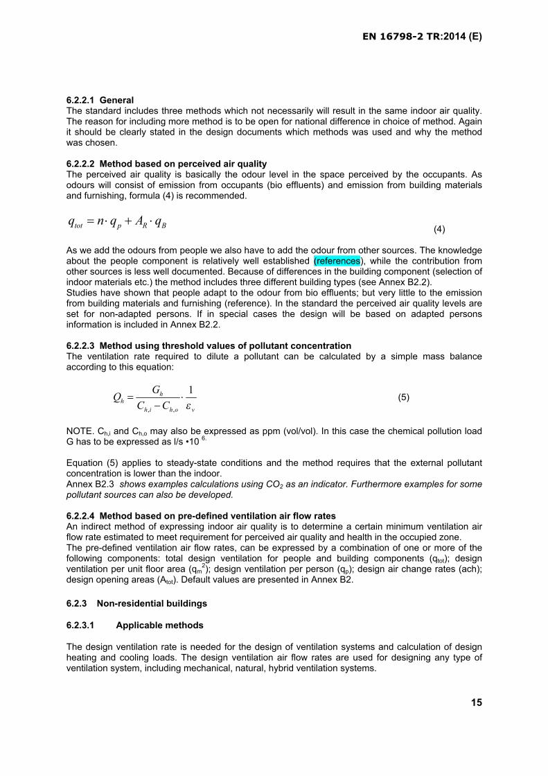
6.2.2.2 Method based on perceived air qualityThe perceived air quality is basically the odour level in the space perceived by the occupants. As odours will consist of emission from occupants (bio effluents) and emission from building materials and furnishing, formula (4) is recommended.
tot p R Bq n q A q (4)
As we add the odours from people we also have to add the odour from other sources. The knowledge about the people component is relatively well established (references), while the contribution from other sources is less well documented. Because of differences in the building component (selection of indoor materials etc.) the method includes three different building types (see Annex B2.2).Studies have shown that people adapt to the odour from bio effluents; but very little to the emission from building materials and furnishing (reference). In the standard the perceived air quality levels are set for non-adapted persons. If in special cases the design will be based on adapted personsinformation is included in Annex B2.2.
6.2.2.3 Method using threshold values of pollutant concentration The ventilation rate required to dilute a pollutant can be calculated by a simple mass balance according to this equation:
, ,
1hh
h i h o v
GQ
C C
(5)
NOTE. Ch,i and Ch,o may also be expressed as ppm (vol/vol). In this case the chemical pollution load G has to be expressed as l/s •10 6.
Equation (5) applies to steady-state conditions and the method requires that the external pollutant concentration is lower than the indoor.Annex B2.3 shows examples calculations using CO2 as an indicator. Furthermore examples for some pollutant sources can also be developed.
6.2.2.4 Method based on pre-defined ventilation air flow ratesAn indirect method of expressing indoor air quality is to determine a certain minimum ventilation air flow rate estimated to meet requirement for perceived air quality and health in the occupied zone. The pre-defined ventilation air flow rates, can be expressed by a combination of one or more of the following components: total design ventilation for people and building components (qtot); design ventilation per unit floor area (qm
2); design ventilation per person (qp); design air change rates (ach); design opening areas (Atot). Default values are presented in Annex B2.
6.2.3 Non-residential buildings
6.2.3.1 Applicable methods
The design ventilation rate is needed for the design of ventilation systems and calculation of design heating and cooling loads. The design ventilation air flow rates are used for designing any type of ventilation system, including mechanical, natural, hybrid ventilation systems.
EN 16798-2 TR:2014 (E)
16
6.2.3.2 Ventilation air flow rates during unoccupied periods.
To avoid building damage and too high level of pollutant concentrations at the start of the occupied hours it may be nescessary to have a basic ventilation during unoccupied hours. It is appropriate to use a level corresponding to the building component. Alternatively full ventilation can be started at a given time before occupation, as described in Annex B2.
6.2.4 Residential buildings
In residential buildings, the occupants can in most cases be considered as adapted to the perceived air quality. Unlike other types of buildings, there is no need to maintain a situation where the indoor air quality is perceived as fresh by non-adapted persons entering the building, as this is an unusual situation for everyday use of the residential building. The main priority in residential buildings is to ensure a healthy indoor environment, and a secondary priority is to prevent damages to the building from excess moisture.
6.2.4.1 Applicable methods
When dealing with ventilation rates, it must be taken into consideration that dwellings have scenario and characteristics different from non-residential buildings (offices, schools, cinemas, bars or restaurants, etc.).
Concerning the scenarios, it’s easy to realize that occupation is completely different from non-residential buildings, in fact:
- occupancy of a dwelling can be strongly variable during the different moments of the day;
- activities can be much different from one another: sleeping, cooking, having a shower,
cleaning, watching tv, etc.
- in residential buildings, the concept of “adapted” people has a great importance: in fact a
dwelling is, for the largest part of the time, a private space where the adaptation is practically
general, differently e.g. from shops, restaurants and similar, where the first impact on
incoming people is essential.
In residential buildings, ventilation systems should take into account flexibility of use of different rooms: typically e.g. bedrooms are scarcely occupied during daytime and occupied during nighttime, contrary to living rooms.
Annex B2, par B2.1.4, of the standard gives methods and details for a suitable design of ventilation systems in residential buildings. Par. B2.4 of this Technical Report explains further, with some examples, how to implement the methods proposed in the standard and how they impact on some types of ventilation systems available on the market.
6.2.4.2 Ventilation air flow rates during non-occupied periods
If the ventilation rate is lowered during unoccupied hours, the ventilation system must start before the building is occupied again or shall not be ventilated during unoccupied hours below a limit value expressed in l/s.m2 of floor area (see Annex B).
6.2.5 Access to operable windows
To allow the building occupants to make airings and to provide contact to the outside it is recommended to include operable windows. This applies to bedrooms and living rooms in dwellings
EN 16798-2 TR:2014 (E)
17
and other buildings with rooms intended for sleeping, e.g. elderly homes. It also applies in offices, schools and child care facilities.
6.2.6 Filtration and air cleaning
To limit the indoor concentration and ingress of outdoor air pollutants one or more of the following methods may be considered:
Placement of air intakes in less polluted areas of the building (e.g. towards courtyards instead
of towards roads)
Filtration
Air cleaning
Design guidelines on air cleaning (filtration and gas phase ) are given in EN13779 and ISO DIS 16814. How to substitute outside air by air cleaning is described in this technical report in annex H.
In order to choose appropriate air filtration and air cleaning solutions, ambient air quality at building location can be considered. When the building is located in an area where the national standard or WHO guideline values for PM10 or PM2,5 are exceeded, particle fine filters (plus a prefilter when appropriate) evaluated according to EN779, or air cleaning devices can be provided to clean the external air at any location prior to its introduction to occupied spaces.
When the building is located in an area where the national standard/WHO guideline value for one or more gaseous contaminants is exceeded such as Ozone, NOX, SOX, PAH, gaseous filtration can be implemented as such or in combination with particle air filtration.
EN13779 provides guidelines for filters performance and filters stage design according to the externalair particles levels and the expected indoor air quality.
Air filters and air cleaning devices are selected and installed to protect ventilation system components and ducts from dust fouling as well. Dust fouling can reduce energy performance of heat exchanges of heating/cooling batteries and heat recovery systems. Note that humidity and temperature conditions combined with dust accumulation may lead to additional load by harmful substances of organic contaminants (microorganisms proliferation and their metabolites).
It is important to avoid that air filters themselves do not become a source of harmful or odourous substances. Regular maintenance, inspections and air filters change minimize the carryover of microorganism and keep supply air clean. EN13779 and Inspection standards provide recommendations and good practices for air filters maintenance and inspection.
6.3 Humidity
The humidity criteria depend partly on the requirements for thermal comfort and indoor air quality and partly on the physical requirements of the building (condensation, mould etc.). For special buildings (museums, historical buildings, churches) particular humidity requirements may exist. For buildings with no other humidity requirements than human occupancy (e.g. offices, schools and residential buildings), humidification or dehumidification is usually not needed. Short-term exposure to very low or high values can be accepted.
EN 16798-2 TR:2014 (E)
18
6.4 Lighting
Windows are strongly favored in buildings for the daylight they deliver, and for the visual contact they provide with the outside environment. However, it is also important to ensure windows do not cause visual or thermal discomfort, or a loss of privacy.
Light is a necessary part to people’s health and wellbeing. Light affects the mood, emotion and mental alertness of people. It can also support and adjust the circadian rhythms and influence people’s physiological and psychological state.
For reasons of comfort and energy in most cases the use of daylight is preferred.
6.4.1 Non residential buildings
The degree of visibility and comfort is wide ranging governed by activity type and duration of required lighting criteria for work places as specified in EN12464-1 and for sports lighting in EN 12193. For some visual tasks in buildings and spaces the required lighting criteria are presented in Annex B4table B4.1.
According to EN 12464-1:2011, clause 4.1, the main lighting requirements are determined by the satisfaction of three basic human needs: visual comfort, visual performance and visual safety.
In order to meet the illumination required in the rooms buildings should have access to daylight to provide all or some of the illumination and during absence of daylight adequate amount of electric lighting should be installed to provide the required illumination. prEN 15193-1 provides details about the effect of daylight on the lighting energy demand (monthly and annual basis), and daylight availability classification as a function of the daylight factor.
Too small windows might provide too little daylight, while too big unprotected windows might lead to overheating.
6.4.2 Residential buildings
Daylight in residential buildings can enter the space by façade and roof light openings or a combination of both. The contribution of daylight will vary in level, direction and spectral composition with time and provides variable modelling and luminance patterns, which is perceived as being beneficial for people in indoor environments. Good daylight provision depends on the size of the area lit by daylight compared to an area, which is not illuminated, by daylight.
6.5 Noise
The Equivalent Continuous Sound Level (Leq,A) is the preferred single value parameter to describenoise. It is the constant sound pressure level which would produce the same sound energy, at a given point, over the same period of time T, as the considered variable sound pressure level.
Leq,A is a very good descriptor of noise due to sources that operate according to different operating conditions in a medium-long time span. It is widely used as descriptor of equipment noise in continuous operation (eg, ventilation, air conditioning, etc.) in most of the regulations and national standards in Europe.
To adequately assess a noise with respect to requirements it is necessary to normalize the equivalent continuous level with respect to reverberation time (Leq,nT,A) to take into account the sound absorption of the room.
EN 16798-2 TR:2014 (E)
19
Leq,nT,A is defined in ISO EN 16032 and ISO EN 10052.
This standard is mainly provided for assessing energy efficiency of buildings, therefore, with respect to noise, only HVAC systems are strictly relevant. Nevertheless these systems are usually strictly connected to plumbing, therefore also the contribution of these last has to be considered to better achieve comfort conditions. Other sources of noise relevant to a comfortable use of the buildings are lifts and motorized systems for opening doors, gates and similar and should be taken int account in the design of buildings. The use of Lmax (FAST) instead of Lmax (SLOW) allow to better include the effect of impulsive phenomena and description of discontinuous noise source functioning (ISO EN16032)
7 Indoor environment parameters for energy calculation
The input values for energy calculations are based on the same concepts as the criteria for design. The criteria presented in the standard are then also reflected in the occupant schedules
7.1 Thermal environment
As the energy calculations may be performed on seasonal, monthly of hourly basis (dynamic simulation) the indoor environment is specified accordingly.
7.1.1 Seasonal calculations
During the between-seasons (with Θrm between around 10 and 15 °C) adjusted upper and lower temperature limits may be used that lie in between the winter and summer values mentioned in table B!.2.
7.1.2 Hourly calculations or dynamic building simulation
The indoor temperatures can be calculated by dynamic building simulations. Recommended values for the acceptable range of the indoor temperature for heating and cooling are presented in Annex B1. The midpoint of the temperature range should be used as a target value but the indoor temperature may fluctuate within the range according to the energy saving features or control algorithm. If the cooling power is limited (mixed mode buildings) the excess indoor temperatures can be estimated using one of the methods described in section 8 of this document.
Assumptions related to allowable exceedance is described in section 8.
7.2 Indoor air quality and ventilation
7.2.1 General
An acceptable level of ventilation is required in both non-residential and residential buildings to achieve good indoor air quality.
7.2.2 Non-residential buildings
The recommended ventilation rates for energy calculations are basically the same as used for design of systems. In systems with variable air flow control and demand controlled ventilation the ventilation rate may vary between maximum, for full occupancy, and minimum, when the considered space is un-occupied. In case of CO2-controlled ventilation the CO2-concentration values in Annex B2 can be
EN 16798-2 TR:2014 (E)
20
used. Recommended values for the excess of CO2 concentration above outdoors CO2 concentration are listed in Annex B2.
7.2.3 Residential buildings
The concept of design ventilation rates and the use of demand controlled ventilation are similar to offices (see above)
7.3 Humidity
The same criteria used for design are also used for energy calculations.
7.4 Lighting
The same criteria used for design are also used for energy calculations.
8 Evaluation of the indoor environment and long term indicators
As the loads of any building vary from place to place and from time to time the designed system may not be able to fulfil the design intent in all rooms during all hours. There is a need to evaluate the long term performance of building in respect of indoor environment. This evaluation is necessary for the display of the climatic factors (indoor environment) in the energy performance certificate (article 6 and 7). This chapter presents indicators for such evaluation and their use. The evaluation of indoor environment of a building is done by evaluating the indoor environment of typical rooms representing different zones in the building. Evaluation shall be based on (1) design (clause 8.1) (2) calculations, (clause 8.2) (3) measurements (clause 8.3) or (4).questionnaires (clause 8.4)
8.1 Design indicators
Evaluation of the category of indoor environment of a building is based on the categories of the following indoor environmental factors:
(1) thermal criteria for winter: Specified design values for indoor temperature during heating (clause 6.1.1)
(2) thermal criteria for summer: Specified design values for indoor temperatures during cooling (clauses 6.1.1 and 6.1.2)
(3) air quality and ventilation criteria: design values for ventilation are in section 6.2.2 for non residential buildings, and for residential buildings in clauses 6.2.3
(4) humidity criteria: design values for humidity are in clauses 6.3
(5) lighting criteria: design values for lighting are in clauses 6.4
(6) noise criteria: design values for noise are given in clauses 6.5
8.2 Calculated indicators of indoor environment
Building simulation is a cost effective way to analyse the performance of buildings. The computer programs used shall be validated according to EN 15265 and EN 15255. Various indicators of indoor
EN 16798-2 TR:2014 (E)
21
environment can be calculated for different purposes. In the following four methods are presented for the thermal evaluation.
8.2.1 Simple indicator
To evaluate the performance of the whole building representative rooms or spaces have to be simulated. The building meets the criteria of a specific category if the rooms representing 95% of building volume meet the criteria of the selected category.
8.2.2 Hourly criteria
Performance of the buildings or rooms with different mechanical or electrical systems can be evaluated by calculating the number of actual hours or the percentage of time when the criteria is met or not.
This procedure is described with an example in the Annex C.
8.2.3 Degree hours criteria
In respect of the thermal environment the degree hours outside the upper or lower boundary can be used as a performance indicator of building for warm or cold season.
This procedure is described with an example in the Annex C.
8.2.4 Overall thermal comfort criteria (weighted PMV criteria)
This procedure is described with an example in the Annex C.
8.3 Measured indicators
Deviations from the selected criteria shall be allowed. Some national criteria express ‘acceptable deviations’ as an acceptable number of hours or percentage of occupancy time outside the criteria based on a yearly evaluation (like 100 to 150 hours assuming 2000 occupancy hours; or 3 % of the occupancy time). This may also be given as weighted hours, where the level of deviation also is taken into account.
If no national criteria for deviations are available the recommended criteria in Annex D can be used. These criteria can be given on a weekly, monthly and yearly basis.
The weather data file used in the building simulation to design the performance of the ventilation system might differ from the actual weather data. A heat wave might influence on the actual performance of the building and cause e.g. overheating. In this matter a longer period of time where the building is outside the designed category may occur.
8.3.1 Thermal environment
The measurements shall be taken in representative rooms at different zones, orientations, with different loads during representative operation periods. The evaluation of the category of indoor environment is based on temporal and spatial distribution of the room temperature. Measurements points and instruments must fulfil the requirements in EN ISO 7726 (EN12599).
EN 16798-2 TR:2014 (E)
22
8.3.2 Indoor air quality and ventilation
Indoor air quality and ventilation of building is evaluated with representative samples taken from different zones of the building.
8.3.2.1 Ventilation method
Ventilation of buildings can be evaluated by measuring air flows in ducts or tracer gas measurementsor by using e.g. CO2 as an indicator.
8.3.2.2 Air quality method
Air quality of building can be evaluated in buildings where people are the main pollution source by measuring the average CO2 concentration in the building, when building is fully occupied. This can be done either with representative samples of room air or by measuring the concentration of the exhaust air.
8.3.3 Lighting
Lighting quality is evaluated by measurements of illuminances on task areas, on surrounding areas and on walls and ceiling. Illuminance uniformity should be greater or equal than the recommended values reported in EN 12464-1 for each kind of surface. The verification procedure in clause 6 of EN 12464-1 shall be followed.
The main parameters determining the luminous environment with respect to electric light and daylight are:
- luminance distribution; - illuminance; - uniformity of illuminance, - glare, - daylight factor, - directionality of light, - lighting in the interior space; - variability of light (levels and colour of light); - colour rendering and colour appearance of the light and
- flicker.
8.3.4 Noise
Noise is evaluated with a representative sample from different air handling systems, zones, windows, and orientation. Normally the criteria for noise do not influence the energy performance of buildings. It could, however, occur in naturally ventilated buildings, that the required amount of outside air cannot be obtained by opening of windows because noise from outside service equipment would violate the pertaining criteria. – unless special measures are taken, e.g. intelligent placement or sound attenuation of air intakes – or user control of the system. Also in the case of mechanical ventilation and cooling, providing the required amount of air could result in unacceptable noise levels from fans.
If adequate ventilation depends on the opening of the windows the equivalent sound pressure level (including the periods the windows are open and room is exposed to the external noise from outside service equipment) shall be used to evaluate the noise. The criteria for noise is given in Annex B5.
This statement of the standard assumes knowledge in the design phase of the actual level of external noise. This data is often not available or can be influenced by the presence of the building itself. It can

EN 16798-2 TR:2014 (E)
23
be difficult to fix design values when the noise level is dependent not only on the operating conditions of the equipment. Many national regulations define criteria for the evaluation of external noise and depend on considerations related to the local use.
8.4 Subjective evaluations
The direct subjective reaction of the occupants can be used for overall evaluation of the indoor environment. Daily, weekly, monthly evaluations using questionnaires for general acceptance of the indoor environment, thermal sensation, perceived air quality shall be used. In Annex E recommended procedures and questionnaires are given for the systematic registration of subjective reactions of building occupants.
9 Inspections and measurement of the indoor environment in existing buildings
Often it is necessary to perform measurements of the indoor environment of the building during inspection to be able to give advice regarding heating loads and system size and operation(article 8 of EPBD) and the cooling loads and system size (article 9 of EPBD) .
Requirements for inspection can be found at national level or in the standards see also 6.2 in reference EN 15378.
If the inspection requires measurement of the indoor environment the following procedures shall be followed.
9.1 Measurements
In existing buildings measurements might be used to check whether the performance of the building and it’s building service systems (ventilation system, heating and cooling devices, artificial lighting) meets the design requirements. In the paragraphs below is indicated how such measurements can be conducted for each indoor environmental quality parameter.
9.1.1 Thermal environment
The measurement instrumentation used for evaluation of the thermal environment shall meet the requirements given in EN ISO 7726.
The recommendations given in EN ISO 7726 should be followed as far as the location of measurement instrumentation within the spaces is concerned.
Measurements shall be made where occupants are known to spend most of their time and underrepresentative weather conditions of the cold and warm season. For the winter (heating season) measurements at or below mean outside temperatures for the three coldest months of the year, and for the summer (cooling season) measurements at or above statistic average outside temperatures for the three warmest months of the year with clear sky.
The measurement period for all measured parameters should be long enough to be representative, for example 10 days.
Air temperature in a room can be used in long term measurements and corrected for large hot or cold surfaces to estimate the operative temperature of the room.
EN 16798-2 TR:2014 (E)
24
9.1.2 Indoor air quality
Indoor air quality measurements are usually based on the indirect approach of measuring ventilation rates. However, indoor air quality depends as well on the presence of specific indoor pollutants that can degrade occupants’ perception of indoor air quality or impair occupants’ health (e.g. smell, sick building symptoms) or both..
Ventilation measurements should show that the requirements for fresh air supply are met. In additioninvestigation and measurements of specific pollutants (e.g. formaldehyde, other Volatile Organic Compounds, fine dust PM10 or PM2,5) may be needed to identify levels, potential sources (indoor or outdoor) and strategies to be implemented for remediation such as :
Indoor air pollutant source emission control and reduction,
Ventilation to dilute air pollutants concentrations,
Outdoor air filtration at mechanical ventilation inlets,
Additional pollutant specific air cleaning.
Annexe I provides as reference WHO guidelines values for indoor and outdoor air pollutants
How this should be done is outside the scope of this document.
An exception is the measurement of CO2: In buildings where people are the main pollution sources the ventilation rates (per person or per m2) can be estimated using CO2 measurement
Measurements shall be made where occupants are known to spend most of their time, preferably at head level during typical high load conditions.
CO2 measurements should preferably be made under winter conditions, as normally fresh air supply is lowest during the colder months (limited use of operable windows, partly closed facade shutters due to draught risk). In some cases momentary measurements at ‘worst case times’ (e.g. end of the morning or end of the afternoon in for example an office or school) might be sufficient.
In larger buildings not all rooms need to be evaluated and measurements in representative rooms might be enough.
If the design is based on specified amount of outside air supply, this amount should be confirmed by measurement at room level. A direct measurement in the supply duct or at the supply grill is often more practical and precise than the measurement of CO2 concentrations.
The measurement instrumentation used for evaluation of the air supply shall meet the requirements given in EN 12599.
First the total fresh air supply for the whole building should be measured and translated into an average per m2 value. Also in a (representatively selected) sample of rooms the fresh air supply ‘at room level’ should be measured. The latter should be translated in both a fresh air supply per m2 and a fresh air supply per person value, taking into account actual occupancy levels and design occupancy levels.
Measurements shall be made under 'semi-worst case weather conditions‘ which normally are the winter months. In many mechanically ventilated buildings in winter recirculation is used. Obviously the air supply at room level values should be corrected for recirculation during periods when recirculation is used.
EN 16798-2 TR:2014 (E)
25
When constant volume mechanical ventilation systems are used, instantaneous measurements are sufficient.
In buildings or spaces with variable volume systems the air supply (at room level) should be measured in both minimum and maximum position.
9.1.3 Indoor Light quality measurements based on illuminance.
Illuminances shall be measured both on task areas and on surrounding areas to conform to values recommended in EN 12464-1 at all operational times. Other parameters as UGR, Ra, etc. shall be checked, according to EN 12464-1.
Illuminance levels measurments of artificial lighting are carried out without the presence of daylight. Preferably measurements of daylight shall be carried out during an average cloudy day.
The maintained illuminance values shall be measured on the horizontal plane in the occupational zone at approximately 0,8 m for regular occupied spaces and at 0,1 m in circulation areas and sports halls.
Measurement shall be carried out in compliance with EN 13032.
10 Classification and certification of the indoor environment.
The information of indoor environment of the building should be included with the energy certificate of the building (EPBD article 7) so that total performance of building can be evaluated. For this certificate the classification of indoor environment is necessary. For the certification it may be necessary to integrate complex indoor environment information into a simple overall indicator of indoor environmental quality of the building.
Due to the many parameters and insufficient knowledge on the combined influence of the indoor environmental parameters, it is recommended to make an overall classification only based on thermal environment and indoor air quality.
10.1 Detailed classification and certification
The evaluation of the indoor environment includes (1) thermal criteria for winter, (2) thermal criteria for summer, (3) air quality and ventilation criteria, (4) lighting criteria, (5) acoustic criteria. Classification of indoor environment can be based on showing the design criteria for each parameter, calculations or measurements over a time period (week, month, year) of relevant parameters like room temperature, ventilation rates, humidity, and CO2 concentrations. The basis of evaluation has to be specified in the classification and certification. An example is shown in Annex F.
10.2 Recommended overall evaluation of the indoor environment and certification
For the overall evaluation it is recommended that a comfort “foot-print” is given for thermal conditions and indoor air quality conditions separately. This can be shown as the percentage of time the indoor environment (temperatures, ventilation rates or CO2 concentrations are within the different categories ( I, II, III, and IV) . Examples are included in Annex F.
EN 16798-2 TR:2014 (E)
26
Annex A(informative)
Information about national Annexes
The aim of this Annex A of the TR is to remind that Annexes A1 to A7 of the Standard give empty tables suitable for national implementation of the standard itself, if values different from those shown in Annexes B1 to B7 are considered more appropriate.
Explanations and discussions on the relevant items of Annexe A1 to A7 of the standard are given in the following Annexes B1 to B7 of this TR.
The present Annex A cn be used to provide additional national comments to the national annex A of prEN16798-1
EN 16798-2 TR:2014 (E)
27
Annex B1(informative)
Recommended criteria for the thermal environment
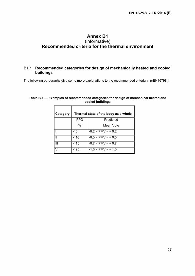
B1.1 Recommended categories for design of mechanically heated and cooled buildings
The following paragraphs give some more explanations to the recommended criteria in prEN16798-1.
Table B.1 — Examples of recommended categories for design of mechanical heated and cooled buildings
Category Thermal state of the body as a whole
PPD
%
Predicted
Mean Vote
I < 6 -0.2 < PMV < + 0.2
II < 10 -0.5 < PMV < + 0.5
III < 15 -0.7 < PMV < + 0.7
VI < 25 -1.0 < PMV < + 1.0
EN 16798-2 TR:2014 (E)
28
Table B.2 — Examples of recommended design values of the indoor operative temperature in winter en summer for buildings with mechanical cooling systems;
Type of building/ space Category Operative temperature oC
Minimum for heating
(winter season), ~ 1,0
clo
Maximum for cooling
(summer season), ~ 0,5 clo
Residential buildings: living spaces (bed
rooms, drawing room, kitchen etc)
Sedentary ~ 1,2 met
I 21,0 25,5
II 20,0 26,0
III 18,0 27,0
IV 16 28
Residential buildings: other spaces:
storages, halls, etc)
Standing-walking ~ 1,6 met
I 18,0
II 16,0
III 14,0
IV
Single office (cellular office)
Sedentary ~ 1,2 met
I 21,0 25,5
II 20,0 26,0
III 19,0 27,0
IV 17 28
Landscaped office (open plan office)
Sedentary ~ 1,2 met
I 21,0 25,5
II 20,0 26,0
III 19,0 27,0
Conference room
Sedentary ~ 1,2 met
I 21,0 25,5
II 20,0 26,0
III 19,0 27,0
IV 17 28
Auditorium
Sedentary ~ 1,2 met
I 21,0 25,5
II 20,0 26,0
III 19,0 27,0
Cafeteria/Restaurant
Sedentary ~ 1,2 met
I 21,0 25,5
II 20,0 26,0
III 19,0 27,0
IV 17 28
Classroom
Sedentary ~ 1,2 met
I 21,0 25,0
II 20,0 26,0
III 19,0 27,0
IV 17 28
Kindergarten
Standing/walking ~ 1,4 met should this be
1,2 like other sedentary
I 19,0 24,5
II 17,5 25,5
III 16,5 26,0
IV
Department store
Standing-walking ~ 1,6 met
I 17,5 24,0
II 16,0 25,0
III 15,0 26,0
IV
EN 16798-2 TR:2014 (E)
29
Note: during the between seasons (with Θrm between 10 oC and 15 oC) temperature limits that lie in between the winter and summer values may be used.
It can be difficult to set recommended values for kindergartens and department stores. In both
building types you will have occupants with different clothing and activity level. So one set of criteria
will not be applicable to all occupants.
Local Thermal Discomfort
The following figure and table give ranges for local thermal discomfort parameters for the three categories for design of buildings and HVAC systems .
The max. allowable mean air velocity is a function of local air temperature and turbulence intensity. The turbulence intensity may vary between 30% and 60% in spaces with mixed flow air distribution. In spaces with displacement ventilation or without mechanical ventilation, the turbulence intensity may be lower.
Figure B1.1a: Maximum allowable mean air velocity as a function of local air temperature and turbulence intensity for the three categories of the thermal environment. ta,l: local air
temperature, la,v : local mean air velocity, Tu: turbulence intensity. (ISO EN 7730)
Draught is an unwanted local cooling of the body caused by air movement. The discomfort due to draught may be expressed as the percentage of people predicted to be bothered by draught. The draught rating (DR) may be calculated by the following equation (model of draught):
DR = (34-ta,l) (va,l - 0,05) 0.62 (0.37· va,l·Tu+3.14)
For va < 0.05 m s -1 insert va = 0.05 m s -1.
For DR > 100 % use DR = 100 %.
where
DR is the draught rating, i.e. the percentage of people dissatisfied due to draught
ta,l is the local air temperature in degrees Celsius, 20 °C - 26 °C.
18 20 22 24 26 oC
0
0.1
0.2
0.3
0.4
m s-1
20%
40%
60%
Tu = 10%
v a,l
A: DR = 10%
ta,l
18 20 22 24 26 oC
0
0.1
0.2
0.3
0.4
m s-1
20%
40%
60%
Tu=
10%
va,l
B: DR = 20%
ta,l
18 20 22 24 26 oC
0
0.1
0.2
0.3
0.4
m s-1
20%
40%
60%
Tu=
10%
va,l
C: DR = 30%
ta,l
EN 16798-2 TR:2014 (E)
30
va,l is the local mean air velocity in meters per second, < 0,5 m s-1
Tu is the local turbulence intensity (%) defined as the ratio of the standard deviation of the local air velocity to the local mean air velocity, 10% to 60%
The model applies to people at light, mainly sedentary activity with a thermal sensation for the whole body close to neutral and for prediction of draught at the neck. At arms and feet level, the model may overestimate the predicted draught rating. The sensation of draught is lower at activities higher than sedentary (> 1.2 met) and for people feeling warmer than neutral.
Vertical air temperature difference
A high vertical air temperature difference between head and ankles may cause discomfort. Figure B1.1b shows the percentage of dissatisfied as a function of the vertical air temperature difference between head and ankles (1,1 and 0,1 m above the floor for seated persons). The figure applies when the temperature increases upwards. People are less sensitive for decreasing temperature.
0 2 4 6 8 10 oC
1
2
4
10
20
40
60
%80
6
ta,v
PD
Figure B1.1b - Local discomfort caused by vertical air temperature difference. ta,v: vertical air temperature difference between head and feet, PD: percent dissatisfied due to local discomfort
caused by vertical air temperature gradient.
Warm and cool floors
If the floor is too warm or too cool, the occupants may feel uncomfortable due to warm or cool feet. For people wearing light indoor shoes, it is the temperature of the floor rather than the material of the
5 10 15 20 25 30 35 40oC
1
2
4
68
10
20
40
6080%
tf
PD
EN 16798-2 TR:2014 (E)
31
Figure B1.1c - Local thermal discomfort caused by warm or cold floors. tf: Floor temperature, PD: percent dissatisfied due to local discomfort caused by cold or warm floors.
floor covering which is important for the comfort. Figure B1.1c shows the percentage of dissatisfied as a function of the floor temperature. This diagram is based on studies with standing and/or sedentary people. For people sitting or lying on the floor similar values may be used. For longer occupancy the results are not valid for electrically heated floors. By electrical heating a certain heat input is provided independent of the surface temperature. A water based heating system will not produce temperatures higher than the water temperature.For spaces, which people occupy with bare feet, please see ISO/TS 13732-2.
Radiant Asymmetry
Radiant asymmetry may also cause discomfort. People are most sensitive to radiant asymmetry caused by warm ceilings or cool walls (windows). Figure B1.1d shows the percentage of dissatisfied as a function of the radiant temperature asymmetry caused by a warm ceiling, a cool wall, a cool ceiling or by a warm wall. For horizontal radiant asymmetry, Figure B1.1d applies from side-to-side (left/right or right/left) asymmetry. For horizontal asymmetry, no other positions of the body in relation to the surfaces cause higher asymmetry discomfort.
A B
C D
0 5 10 15 20 25 30 35oC
1
2
4
68
10
20
40
6080%
tpr
PD
Figure B1.1d - Local thermal discomfort caused by radiant temperature asymmetry. tpr: radiant temperature asymmetry, PD: percent dissatisfied due to local discomfort caused by
radiant asymmetry. A: Warm ceiling, B: Cool wall, C: Cool ceiling, D: Warm wall.
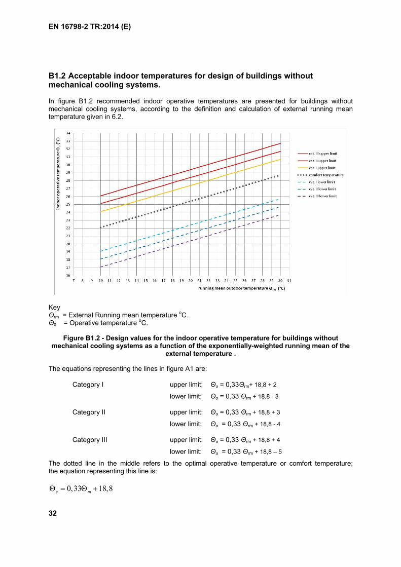
EN 16798-2 TR:2014 (E)
32
B1.2 Acceptable indoor temperatures for design of buildings without mechanical cooling systems.
In figure B1.2 recommended indoor operative temperatures are presented for buildings without mechanical cooling systems, according to the definition and calculation of external running mean temperature given in 6.2.
KeyΘrm = External Running mean temperature oC.Θ0 = Operative temperature oC.
Figure B1.2 - Design values for the indoor operative temperature for buildings without mechanical cooling systems as a function of the exponentially-weighted running mean of the
external temperature .
The equations representing the lines in figure A1 are:
Category I upper limit: Θo = 0,33Θrm+ 18,8 + 2
lower limit: Θo = 0,33 Θrm + 18,8 - 3
Category II upper limit: Θo = 0,33 Θrm + 18,8 + 3
lower limit: Θo = 0,33 Θrm + 18,8 - 4
Category III upper limit: Θo = 0,33 Θrm + 18,8 + 4
lower limit: Θo = 0,33 Θrm + 18,8 – 5
The dotted line in the middle refers to the optimal operative temperature or comfort temperature; the equation representing this line is:
0,33 18,8c m
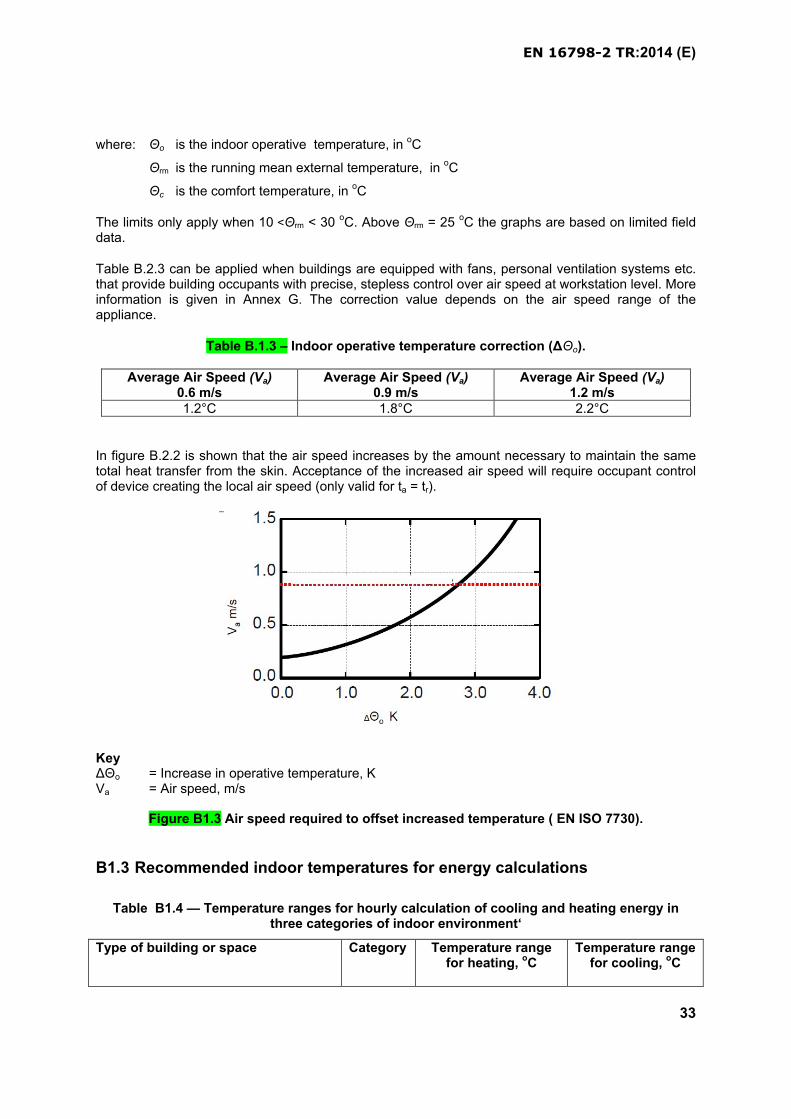
EN 16798-2 TR:2014 (E)
33
where: Θo is the indoor operative temperature, in oC
Θrm is the running mean external temperature, in oC
Θc is the comfort temperature, in oC
The limits only apply when 10 <Θrm < 30 oC. Above Θrm = 25 oC the graphs are based on limited field data.
Table B.2.3 can be applied when buildings are equipped with fans, personal ventilation systems etc. that provide building occupants with precise, stepless control over air speed at workstation level. More information is given in Annex G. The correction value depends on the air speed range of the appliance.
Table B.1.3 – Indoor operative temperature correction (ΔΘo).
Average Air Speed (Va)0.6 m/s
Average Air Speed (Va)0.9 m/s
Average Air Speed (Va)1.2 m/s
1.2°C 1.8°C 2.2°C
In figure B.2.2 is shown that the air speed increases by the amount necessary to maintain the same total heat transfer from the skin. Acceptance of the increased air speed will require occupant control of device creating the local air speed (only valid for ta = tr).
KeyΔΘo = Increase in operative temperature, KVa = Air speed, m/s
Figure B1.3 Air speed required to offset increased temperature ( EN ISO 7730).
B1.3 Recommended indoor temperatures for energy calculations
Table B1.4 — Temperature ranges for hourly calculation of cooling and heating energy in three categories of indoor environment‘
Type of building or space Category Temperature range for heating, oC
Temperature range for cooling, oC
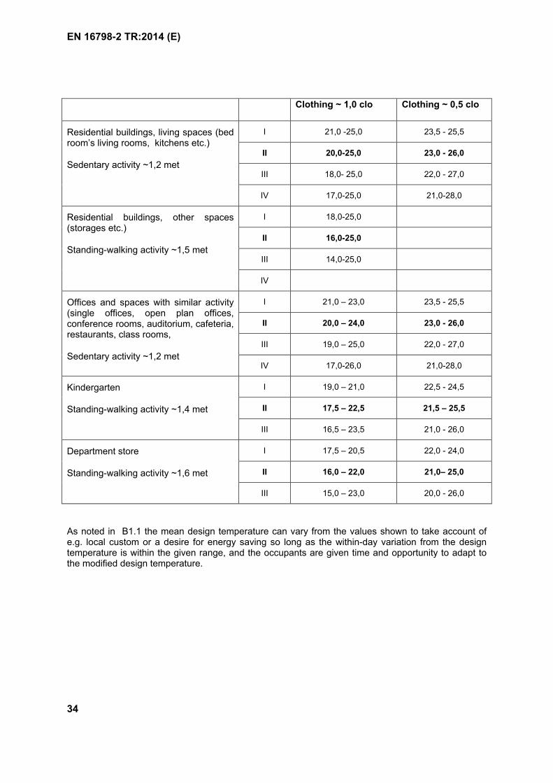
EN 16798-2 TR:2014 (E)
34
Clothing ~ 1,0 clo Clothing ~ 0,5 clo
Residential buildings, living spaces (bed room’s living rooms, kitchens etc.)
Sedentary activity ~1,2 met
I 21,0 -25,0 23,5 - 25,5
II 20,0-25,0 23,0 - 26,0
III 18,0- 25,0 22,0 - 27,0
IV 17,0-25,0 21,0-28,0
Residential buildings, other spaces (storages etc.)
Standing-walking activity ~1,5 met
I 18,0-25,0
II 16,0-25,0
III 14,0-25,0
IV
Offices and spaces with similar activity (single offices, open plan offices, conference rooms, auditorium, cafeteria, restaurants, class rooms,
Sedentary activity ~1,2 met
I 21,0 – 23,0 23,5 - 25,5
II 20,0 – 24,0 23,0 - 26,0
III 19,0 – 25,0 22,0 - 27,0
IV 17,0-26,0 21,0-28,0
Kindergarten
Standing-walking activity ~1,4 met
I 19,0 – 21,0 22,5 - 24,5
II 17,5 – 22,5 21,5 – 25,5
III 16,5 – 23,5 21,0 - 26,0
Department store
Standing-walking activity ~1,6 met
I 17,5 – 20,5 22,0 - 24,0
II 16,0 – 22,0 21,0– 25,0
III 15,0 – 23,0 20,0 - 26,0
As noted in B1.1 the mean design temperature can vary from the values shown to take account of e.g. local custom or a desire for energy saving so long as the within-day variation from the design temperature is within the given range, and the occupants are given time and opportunity to adapt to the modified design temperature.
EN 16798-2 TR:2014 (E)
35
ANNEX B2(informative)
Basis for the criteria for indoor air quality and ventilation rates
B2.1 General
There does not exist a common standard index for the indoor air quality. The indoor air quality is therefore expressed as the required level of ventilation or CO2 concentrations. It is generally accepted that the indoor air quality is influenced by emission from people and their activities (bio effluents, cooking,), from building and furnishing, and from the HVAC system itself. The two last sources are normally called the building components. The required ventilation is based on health and comfort criteria. In most cases the health criteria will also be met by the required ventilation for comfort. Health effects may be attributed to specific components of emission and if the concentration of one source is reduced the concentration of others will also be reduced. Comfort is more related to the perceived air quality (odour, irritation). In these cases different sources of emission may have an odour component that adds to the odour level. There his however no general agreement on how different sources of emission should be added together. In the present standard the criteria will in the following be expressed in different ways.
Section B2.2 - Method based on perceived air quality.
Section B2.3 - Method using limit values of gas concentration.
Section B2.4 - Ventilation air flow rates for residential buildings.
For air-flow controlled systems (typically mechanical systems), outdoor air flow equivalent to two air volumes of the ventilated space shall be delivered to the space before occupancy (e.g. if the ventilation rate is 2 ach, the ventilation is started one hour before the occupancy, if the ventilation rate is 1 ach, the ventilation is started two hours before the occupancy). Instead of pre-start the ventilation system, buildings can be ventilated, during the unoccupied periods, with lower ventilation rate than during the occupied period. In this case, the minimum ventilation rate shall be equivalent to the required level for the building component in the following Table B2.
For CO2 and temperature controlled systems the ventilation requirement is fulfilled if the limits for CO2
and temperature are fulfilled.
Infiltration can be calculated as a part of the ventilation air flow rate (leakage assumptions should be described, see EN15242).
B2.2 - Method based on perceived air quality
The calculated design ventilation rate is from two components
Table B1 ventilation for pollution from the occupants (bio effluents).
Table B2 ventilation for the pollution from the building and systems.
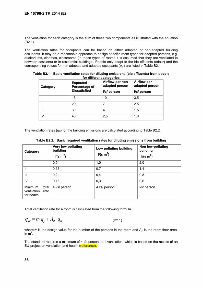
EN 16798-2 TR:2014 (E)
36
The ventilation for each category is the sum of these two components as illustrated with the equation (B2.1).
The ventilation rates for occupants can be based on either adapted or non-adapted building occupants. It may be a reasonable approach to design specific room types for adapted persons, e.g. auditoriums, cinemas, classrooms (in these types of rooms it is assumed that they are ventilated in between sessions) or in residential buildings.. People only adapt to the bio effluents (odour) and the corresponding values for non adapted and adapted occupants (qp ) are listed in Table B2.1:
Table B2.1 - Basic ventilation rates for diluting emissions (bio effluents) from peoplefor different categories
CategoryExpected Percentage of Dissatisfied
Airflow per non-adapted person
l/s/ person
Airflow per adapted person
l/s/ person
I 15 10 3,5
II 20 7 2.5
III 30 4 1.5
IV 40 2,5 1.0
The ventilation rates (qB) for the building emissions are calculated according to Table B2.2.
Table B2.2. Basic required ventilation rates for diluting emissions from building
Category
Very low polluting building
l/(s m2)
Low polluting building
l/(s m2)
Non low-polluting building
l/(s m2)
I 0,5 1,0 2,0
II 0,35 0,7 1,4
III 0,2 0,4 0,8
IV 0,15 0,3 0,6
Minimum total ventilation rate for health
4 l/s/ person 4 l/s/ person l/s/ person
Total ventilation rate for a room is calculated from the following formula
tot p R Bq n q A q (B2.1)
where:n is the design value for the number of the persons in the room and AR is the room floor area, in m2.
The standard requires a minimum of 4 l/s person total ventilation, which is based on the results of an EU-project on ventilation and health (reference).
EN 16798-2 TR:2014 (E)
37
Examples of the total ventilation rates for non-industrial, non-residential buildings based on these values, calculated using the equation (B2.1) with default occupancy densities, are given in the tablesB2.3 (for non-adapted persons) and B2.4 (fr adapted persons). The values in the table are based on complete mixing in the room (concentration of pollutants is equal in exhaust and in occupied zone). Ventilation rates can be adjusted according to the ventilation efficiency if the performance of air distribution differs from complete mixing, and can be reliably proven (see EN 13779).
The total ventilation rate can either be given as l/(s m2) or as l/s/person as shown in tables B2.3 and B2.4.
A building is by default a low-polluting building unless prior activity has resulted in pollution of the building (e.g. smoking). In this case, the building shall be regarded as non-low polluting. The category very low-polluting requires that the majority of building materials used for finishing the interior surfaces meet the national or international criteria of very low-polluting materials. An example of how to define very low-polluting building materials is given in Annex B3.
EN 16798-2 TR:2014 (E)
38
Table C.3 — Non-adapted persons. Examples of recommended ventilation rates for non-residential buildings with default occupant density for three categories of pollution from
building itself.
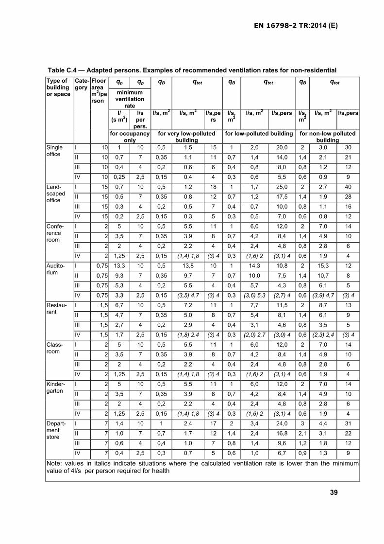
EN 16798-2 TR:2014 (E)
39
Table C.4 — Adapted persons. Examples of recommended ventilation rates for non-residential
Type of building or space
Cate-gory
Floor area m2/person
qp qp qB qtot qB qtot qB qtot
minimum ventilation
ratel/
(s m2)l/sper
pers.
l/s, m2 l/s, m2 l/s,pers
l/s, m2
l/s, m2 l/s,pers l/s,m2
l/s, m2 l/s,pers
for occupancy only
for very low-polluted building
for low-polluted building for non-low polluted building
Single office
I 10 1 10 0,5 1,5 15 1 2,0 20,0 2 3,0 30
II 10 0,7 7 0,35 1,1 11 0,7 1,4 14,0 1,4 2,1 21
III 10 0,4 4 0,2 0,6 6 0,4 0,8 8,0 0,8 1,2 12
IV 10 0,25 2,5 0,15 0,4 4 0,3 0,6 5,5 0,6 0,9 9
Land-scaped office
I 15 0,7 10 0,5 1,2 18 1 1,7 25,0 2 2,7 40
II 15 0,5 7 0,35 0,8 12 0,7 1,2 17,5 1,4 1,9 28
III 15 0,3 4 0,2 0,5 7 0,4 0,7 10,0 0,8 1,1 16
IV 15 0,2 2,5 0,15 0,3 5 0,3 0,5 7,0 0,6 0,8 12
Confe-rence room
I 2 5 10 0,5 5,5 11 1 6,0 12,0 2 7,0 14
II 2 3,5 7 0,35 3,9 8 0,7 4,2 8,4 1,4 4,9 10
III 2 2 4 0,2 2,2 4 0,4 2,4 4,8 0,8 2,8 6
IV 2 1,25 2,5 0,15 (1,4) 1,8 (3) 4 0,3 (1,6) 2 (3,1) 4 0,6 1,9 4
Audito-rium
I 0,75 13,3 10 0,5 13,8 10 1 14,3 10,8 2 15,3 12
II 0,75 9,3 7 0,35 9,7 7 0,7 10,0 7,5 1,4 10,7 8
III 0,75 5,3 4 0,2 5,5 4 0,4 5,7 4,3 0,8 6,1 5
IV 0,75 3,3 2,5 0,15 (3,5) 4.7 (3) 4 0,3 (3,6) 5,3 (2,7) 4 0,6 (3,9) 4,7 (3) 4
Restau-rant
I 1,5 6,7 10 0,5 7,2 11 1 7,7 11,5 2 8,7 13
II 1,5 4,7 7 0,35 5,0 8 0,7 5,4 8,1 1,4 6,1 9
III 1,5 2,7 4 0,2 2,9 4 0,4 3,1 4,6 0,8 3,5 5
IV 1,5 1,7 2,5 0,15 (1,8) 2.4 (3) 4 0,3 (2,0) 2,7 (3,0) 4 0,6 (2,3) 2,4 (3) 4
Class-room
I 2 5 10 0,5 5,5 11 1 6,0 12,0 2 7,0 14
II 2 3,5 7 0,35 3,9 8 0,7 4,2 8,4 1,4 4,9 10
III 2 2 4 0,2 2,2 4 0,4 2,4 4,8 0,8 2,8 6
IV 2 1,25 2,5 0,15 (1,4) 1,8 (3) 4 0,3 (1,6) 2 (3,1) 4 0,6 1,9 4
Kinder-garten
I 2 5 10 0,5 5,5 11 1 6,0 12,0 2 7,0 14
II 2 3,5 7 0,35 3,9 8 0,7 4,2 8,4 1,4 4,9 10
III 2 2 4 0,2 2,2 4 0,4 2,4 4,8 0,8 2,8 6
IV 2 1,25 2,5 0,15 (1,4) 1,8 (3) 4 0,3 (1,6) 2 (3,1) 4 0,6 1,9 4
Depart-ment store
I 7 1,4 10 1 2,4 17 2 3,4 24,0 3 4,4 31
II 7 1,0 7 0,7 1,7 12 1,4 2,4 16,8 2,1 3,1 22
III 7 0,6 4 0,4 1,0 7 0,8 1,4 9,6 1,2 1,8 12
IV 7 0,4 2,5 0,3 0,7 5 0,6 1,0 6,7 0,9 1,3 9
Note: values in italics indicate situations where the calculated ventilation rate is lower than the minimum value of 4l/s per person required for health

EN 16798-2 TR:2014 (E)
40
buildings with default occupant density for three categories of pollution from building itself.
Type of building or space
Cate-gory
Floor area m2/per-son
qp qB qtot qB qtot qB qtot
Adapted qp
according to table B1l/s, m2 l/s,per
sonl/s,m2 l/s,m2 l/s,per
sonl/s,m2 l/s,m2 l/s,per
sonl/s,m2 l/s,m2 l/s,per
son
for occupancy
for very low-polluted building
for low-polluted building
for non-low polluted building
Confe-rence room
I 2 1,75 3,5 0,5 2,25 4,5 1 2,75 5,5 2 3,75 7,5
II 2 1,25 2,5 0,35 1,60 (3,2)4 0,7 1,95 (3,9)4 1,4 2,65 5,3
III 2 0,75 1,5 0,3 1,05 (2,1)4 0,4 1,15 (2,3)4 0,8 1,55 (3,1)4
IV 2 0,50 1 0,25 0,75 (1,5)4 0,3 0,80 (1,6)4 0,6 1,10 (2,2)4
Audito-rium
I 0,75 4,67 3,5 0,5 5,17 (3,9)4 1 5,67 4,3 2 6,67 5,0
II 0,75 3,33 2,5 0,35 3,68 (2,8)4 0,7 4,03 (3,0)4 1,4 4,73 (3,6)4
III 0,75 2,00 1,5 0,3 2,30 (1,7)4 0,4 2,40 (1,8)4 0,8 2,80 (2,1)4
IV 0,75 1,33 1 0,25 1,58 (1,2)4 0,3 1,63 (1,2)4 0,6 1,93 (1,5)4
Class room
I 2 1,75 3,5 0,5 2,25 4,5 1 2,75 5,5 2 3,75 7,5
II 2 1,25 2,5 0,35 1,60 (3,2)4 0,7 1,95 (3,9)4 1,4 2,65 5,3
III 2 0,75 1,5 0,3 1,05 (2,1)4 0,4 1,15 (2,3)4 0,8 1,55 (3,1)4
IV 2 0,50 1 0,25 0,75 (1,5)4 0,3 0,80 (1,6)4 0,6 1,10 (2,2)4
Note: values in italics indicate situations where the calculated ventilation rate is lower than the minimum value of 4l/s per person required for health
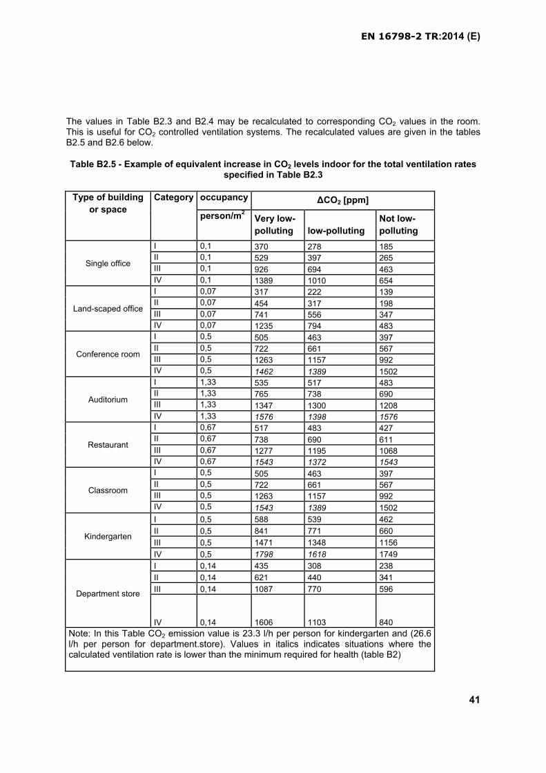
EN 16798-2 TR:2014 (E)
41
The values in Table B2.3 and B2.4 may be recalculated to corresponding CO2 values in the room. This is useful for CO2 controlled ventilation systems. The recalculated values are given in the tables B2.5 and B2.6 below.
Table B2.5 - Example of equivalent increase in CO2 levels indoor for the total ventilation rates specified in Table B2.3
Type of building
or space
Category occupancy ΔCO2 [ppm]
person/m2Very low-
polluting low-polluting
Not low-
polluting
Single office
I 0,1 370 278 185
II 0,1 529 397 265
III 0,1 926 694 463
IV 0,1 1389 1010 654
Land-scaped office
I 0,07 317 222 139
II 0,07 454 317 198
III 0,07 741 556 347
IV 0,07 1235 794 483
Conference room
I 0,5 505 463 397
II 0,5 722 661 567
III 0,5 1263 1157 992
IV 0,5 1462 1389 1502
Auditorium
I 1,33 535 517 483
II 1,33 765 738 690
III 1,33 1347 1300 1208
IV 1,33 1576 1398 1576
Restaurant
I 0,67 517 483 427
II 0,67 738 690 611
III 0,67 1277 1195 1068
IV 0,67 1543 1372 1543
Classroom
I 0,5 505 463 397
II 0,5 722 661 567
III 0,5 1263 1157 992
IV 0,5 1543 1389 1502
Kindergarten
I 0,5 588 539 462
II 0,5 841 771 660
III 0,5 1471 1348 1156
IV 0,5 1798 1618 1749
Department store
I 0,14 435 308 238
II 0,14 621 440 341
III 0,14 1087 770 596
IV 0,14 1606 1103 840
Note: In this Table CO2 emission value is 23.3 l/h per person for kindergarten and (26.6 l/h per person for department.store). Values in italics indicates situations where the calculated ventilation rate is lower than the minimum required for health (table B2)

EN 16798-2 TR:2014 (E)
42
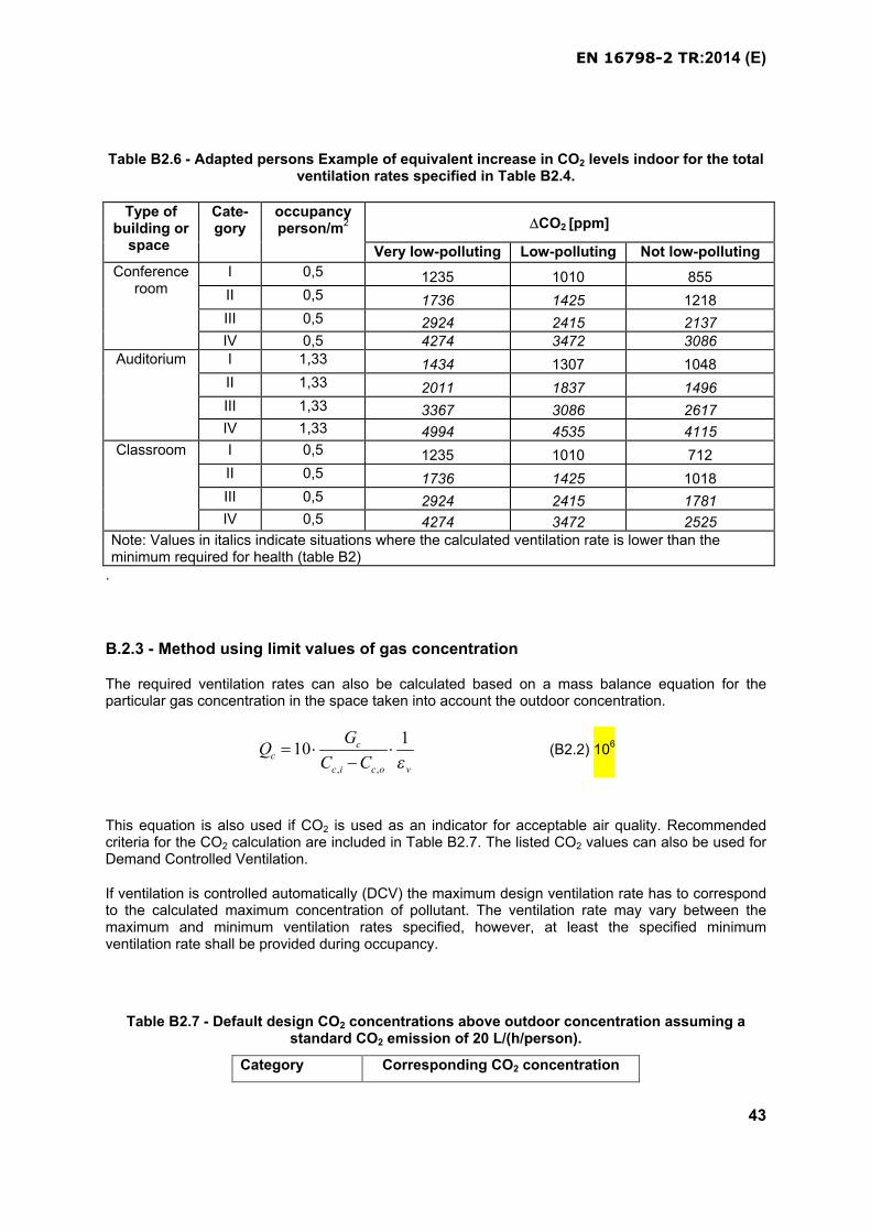
EN 16798-2 TR:2014 (E)
43
Table B2.6 - Adapted persons Example of equivalent increase in CO2 levels indoor for the total ventilation rates specified in Table B2.4.
Type of building or
space
Cate-gory
occupancy person/m2 CO2 [ppm]
Very low-polluting Low-polluting Not low-polluting
Conference room
I 0,5 1235 1010 855II 0,5 1736 1425 1218III 0,5 2924 2415 2137IV 0,5 4274 3472 3086
Auditorium I 1,33 1434 1307 1048II 1,33 2011 1837 1496III 1,33 3367 3086 2617IV 1,33 4994 4535 4115
Classroom I 0,5 1235 1010 712II 0,5 1736 1425 1018III 0,5 2924 2415 1781IV 0,5 4274 3472 2525
Note: Values in italics indicate situations where the calculated ventilation rate is lower than the minimum required for health (table B2)
.
B.2.3 - Method using limit values of gas concentration
The required ventilation rates can also be calculated based on a mass balance equation for the particular gas concentration in the space taken into account the outdoor concentration.
, ,
110 c
c
c i c o v
GQ
C C
(B2.2) 106
This equation is also used if CO2 is used as an indicator for acceptable air quality. Recommended criteria for the CO2 calculation are included in Table B2.7. The listed CO2 values can also be used for Demand Controlled Ventilation.
If ventilation is controlled automatically (DCV) the maximum design ventilation rate has to correspond to the calculated maximum concentration of pollutant. The ventilation rate may vary between the maximum and minimum ventilation rates specified, however, at least the specified minimum ventilation rate shall be provided during occupancy.
Table B2.7 - Default design CO2 concentrations above outdoor concentration assuming a standard CO2 emission of 20 L/(h/person).
Category Corresponding CO2 concentration
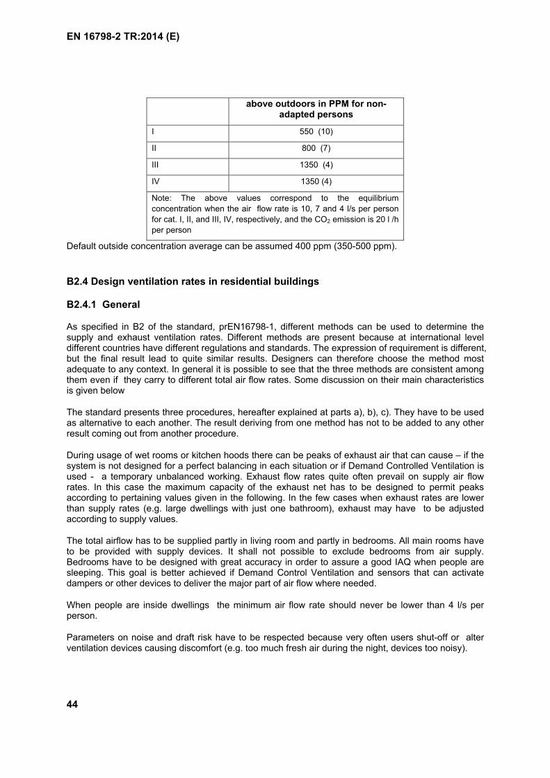
EN 16798-2 TR:2014 (E)
44
above outdoors in PPM for non-adapted persons
I 550 (10)
II 800 (7)
III 1350 (4)
IV 1350 (4)
Note: The above values correspond to the equilibrium
concentration when the air flow rate is 10, 7 and 4 l/s per person
for cat. I, II, and III, IV, respectively, and the CO2 emission is 20 l /h
per person
Default outside concentration average can be assumed 400 ppm (350-500 ppm).
B2.4 Design ventilation rates in residential buildings
B2.4.1 General
As specified in B2 of the standard, prEN16798-1, different methods can be used to determine the supply and exhaust ventilation rates. Different methods are present because at international level different countries have different regulations and standards. The expression of requirement is different, but the final result lead to quite similar results. Designers can therefore choose the method mostadequate to any context. In general it is possible to see that the three methods are consistent among them even if they carry to different total air flow rates. Some discussion on their main characteristics is given below
The standard presents three procedures, hereafter explained at parts a), b), c). They have to be used as alternative to each another. The result deriving from one method has not to be added to any other result coming out from another procedure.
During usage of wet rooms or kitchen hoods there can be peaks of exhaust air that can cause – if the system is not designed for a perfect balancing in each situation or if Demand Controlled Ventilation is used - a temporary unbalanced working. Exhaust flow rates quite often prevail on supply air flow rates. In this case the maximum capacity of the exhaust net has to be designed to permit peaks according to pertaining values given in the following. In the few cases when exhaust rates are lower than supply rates (e.g. large dwellings with just one bathroom), exhaust may have to be adjusted according to supply values.
The total airflow has to be supplied partly in living room and partly in bedrooms. All main rooms have to be provided with supply devices. It shall not possible to exclude bedrooms from air supply. Bedrooms have to be designed with great accuracy in order to assure a good IAQ when people are sleeping. This goal is better achieved if Demand Control Ventilation and sensors that can activate dampers or other devices to deliver the major part of air flow where needed.
When people are inside dwellings the minimum air flow rate should never be lower than 4 l/s per person.
Parameters on noise and draft risk have to be respected because very often users shut-off or alter ventilation devices causing discomfort (e.g. too much fresh air during the night, devices too noisy).
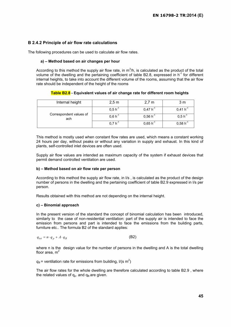
EN 16798-2 TR:2014 (E)
45
B 2.4.2 Principle of air flow rate calculations
The following procedures can be used to calculate air flow rates.
a) – Method based on air changes per hour
According to this method the supply air flow rate, in m3/h, is calculated as the product of the totalvolume of the dwelling and the pertaining coefficient of table B2.8, expressed in h-1 for different internal heights, to take into account the different volume of the rooms, assuming that the air flow rate should be independent of the height of the rooms
Table B2.8 - Equivalent values of air change rate for different room heights
Internal height 2,5 m 2,7 m 3 m
Correspondent values of
ach
0,5 h-1 0,47 h-1 0,41 h-1
0,6 h-1 0,56 h-1 0,5 h-1
0,7 h-1 0,65 h-1 0,58 h-1
This method is mostly used when constant flow rates are used, which means a constant working 24 hours per day, without peaks or without any variation in supply and exhaust. In this kind of plants, self-controlled inlet devices are often used.
Supply air flow values are intended as maximum capacity of the system if exhaust devices that permit demand controlled ventilation are used.
b) – Method based on air flow rate per person
According to this method the supply air flow rate, in l/s , is calculated as the product of the design number of persons in the dwelling and the pertaining coefficient of table B2.9 expressed in l/s per person.
Results obtained with this method are not depending on the internal height.
c) – Binomial approach
In the present version of the standard the concept of binomial calculation has been introduced, similarly to the case of non-residential ventilation: part of the supply air is intended to face the emission from persons and part is intended to face the emissions from the building parts, furniture etc.. The formula B2 of the standard applies:
Bptot qAqnq (B2)
where n is the design value for the number of persons in the dwelling and A is the total dwelling floor area, m2
qB = ventilation rate for emissions from building, l/(s m2)
The air flow rates for the whole dwelling are therefore calculated according to table B2.9 , where the related values of qp. and qB are given.
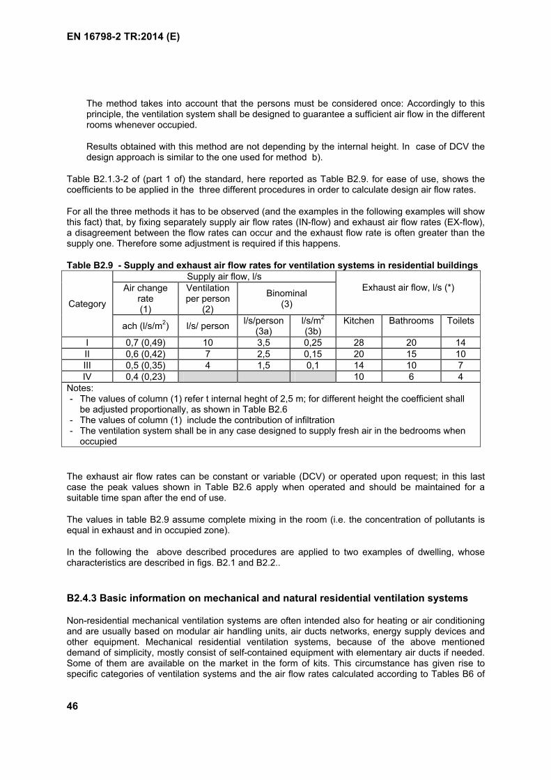
EN 16798-2 TR:2014 (E)
46
The method takes into account that the persons must be considered once: Accordingly to this principle, the ventilation system shall be designed to guarantee a sufficient air flow in the different rooms whenever occupied.
Results obtained with this method are not depending by the internal height. In case of DCV the design approach is similar to the one used for method b).
Table B2.1.3-2 of (part 1 of) the standard, here reported as Table B2.9. for ease of use, shows the coefficients to be applied in the three different procedures in order to calculate design air flow rates.
For all the three methods it has to be observed (and the examples in the following examples will show this fact) that, by fixing separately supply air flow rates (IN-flow) and exhaust air flow rates (EX-flow), a disagreement between the flow rates can occur and the exhaust flow rate is often greater than the supply one. Therefore some adjustment is required if this happens.
Table B2.9 - Supply and exhaust air flow rates for ventilation systems in residential buildings
Category
Supply air flow, l/sExhaust air flow, l/s (*)Air change
rate(1)
Ventilationper person
(2)
Binominal(3)
ach (l/s/m2) l/s/ personl/s/person
(3a)l/s/m2
(3b)Kitchen Bathrooms Toilets
I 0,7 (0,49) 10 3,5 0,25 28 20 14II 0,6 (0,42) 7 2,5 0,15 20 15 10III 0,5 (0,35) 4 1,5 0,1 14 10 7IV 0,4 (0,23) 10 6 4
Notes:- The values of column (1) refer t internal heght of 2,5 m; for different height the coefficient shall
be adjusted proportionally, as shown in Table B2.6- The values of column (1) include the contribution of infiltration- The ventilation system shall be in any case designed to supply fresh air in the bedrooms when
occupied
The exhaust air flow rates can be constant or variable (DCV) or operated upon request; in this last case the peak values shown in Table B2.6 apply when operated and should be maintained for a suitable time span after the end of use.
The values in table B2.9 assume complete mixing in the room (i.e. the concentration of pollutants is equal in exhaust and in occupied zone).
In the following the above described procedures are applied to two examples of dwelling, whose characteristics are described in figs. B2.1 and B2.2..
B2.4.3 Basic information on mechanical and natural residential ventilation systems
Non-residential mechanical ventilation systems are often intended also for heating or air conditioning and are usually based on modular air handling units, air ducts networks, energy supply devices and other equipment. Mechanical residential ventilation systems, because of the above mentioned demand of simplicity, mostly consist of self-contained equipment with elementary air ducts if needed. Some of them are available on the market in the form of kits. This circumstance has given rise to specific categories of ventilation systems and the air flow rates calculated according to Tables B6 of

EN 16798-2 TR:2014 (E)
47
the standard, as previously described, can be achieved by means of different systems and components. Residential natural ventilation systems are often composed of components for continuous ventilation (façade grilles, exhaust stack ducts, window frame grilles) in combination with operable windows for short airings.
The performance of a mechanical or natural ventilation system, from both energy and air quality point of view, can be improved if appropriate devices are adopted to divert the external flow rates from rooms which, at a given moment, are not being used to those which are being used. This approach is usually referred to as Demand Control Ventilation (DCV) and can be achieved by means of suitable sensors of humidity, CO2 concentration, presence or other parameters which can be assumed as indicators of pollution.
There is a wide range of devices and related EN standards covering the characteristics, the evaluation of performance and the classification of residential ventilation systems (EN 13142 and EN 13141,parts 1 to 11). A brief description is given here below.
a) Mechanical exhaust ventilation systems
Fresh air enters the main-rooms through suitable inlet devices, transits through doors or other openings toward the wet-rooms and then is exhausted by one or more fans. The inlet and outlet devices can be equipped with flow rate controls, e.g. self-regulating, to maintain constant flow rate, or based on humidity, CO2 concentration, presence, to adjust the flow rate to the effective requirement (DCV). Inlet devices are usually inserted on the external walls or on the windows; the air ducts are limited to connect the exhaust devices with the fan(s) and from the fan(s) to the exterior.
b) Mechanical supply ventilation systems
Fresh air is introduced by one or more fans in the main-rooms at constant or variable (DCV) flow ratethrough a suitable air duct network and inlet devices, transits through doors or other openings toward the wet-rooms and then is exhausted possibly by one or more fans. In this last case fans can be operated according to different logics: upon request (with or without switch-off delay after use), manually or automatically. It has to be observed that the operation of the exhaust fan(s) can produce a temporary unbalance of the flow rates. Inlet and outlet devices can be as in case a.
c) Mechanical balanced (Double flux) ventilation systems
In these systems, called also “double flux systems”, supply and exhaust air flow rates are introduced in main-rooms and extracted from wet rooms, respectively, through suitable air duct networks and inlet or outlet devices by means separate fans. Usually energy recovery from the exhaust air is performed by means of a heat exchanger or a heat pump. Different strategies of air flow control (DCV or peak exhaust) can be used.
d) Mechanical un-ducted units for single room systems
Supply air flow rates are introduced in each main room by a specific device equipped with fan. Some types are equipped also with extraction fan and recovery heat exchanger. Exhaust air from wet rooms is extracted by specific fans which can be operated according to different logics: upon request (with or without switch-off delay after use), manually or automatically. It has to be observed that the operation of the exhaust fan(s) can produce a temporary un balance of the flow rates.
Type a), b), and c) concern centralized systems, i.e. intended to serve a whole dwelling; type d) units are intended to serve an individual room and the ventilation of the whole dwelling is performed by means of as many devices as the main-rooms, possibly integrated by exhaust devices in the wet-rooms.
When double flow rate for exhaust devices is used, the peak value should be operated during the use of room (e.g. cooking time for the kitchen) and for a suitable time after the use.

EN 16798-2 TR:2014 (E)
48
e) Natural ventilation system
Residential natural ventilation systems are using stack effect and wind pressure to drive the ventilation airflow through the building. Typical inlet components are facade grilles, window grilles, roof window ventilation flaps and openable windows. Typical extract components include extract stack ducts and openable windows.
The system is typically designed to supply air in living rooms and bedrooms, and to extract air from kitchens, toilets and bathrooms.
The dimensioning of the opening area can be based on calculations (e.g. EN 15242 or dynamic simulation tools), or on opening area requirements, e.g. table B7 or national building codes.
The operation of the ventilation system can be based on always-open ventilation openings, which provides acceptable indoor air quality on weekly, monthly and annual level. The operation can also be automated, based on sensors of e.g. humidity or CO2.
B2.4.4 Examples of air flow rate calculation
Example 1 and 2 show the design principle of the different ventilation systems respectively for a two bedrooms dwelling and for a smaller one bedroom dwelling. The air flow rates can be constant or variable, in case of DCV. In this last case the maximum value will be achieved when all the exhaust will be in operation otherwise the air flow rate can be reduced, but never below a value suitable to guarantee 4 l/s per person;.
The air flow for each room is attributed by the designer, considering also to the sizes of the air inlet devices present on the market, certified according the relevant part of EN 13141. All main rooms have to be provided with supply devices. The same air flow is supposed exhausted from K, WC and T. In the choice of the inlet and outlet devices, according to their nominal flow rate, the sum of inlet air flow rate can result to some extent different from exhaust air flow rate. It is advisable to have at least a slight exceeding total exhaust air flow rate to avoid risk of condensation which could occur if exceeding supply flow rate would be exhausted though windows frames and/or cracks, particularly in cold climates. Note that if the site of the building is of radon risk, the indoor depression could be critical: in this case special designed approach has to be provided (e.g. crawlspace ventilation).
B2.4.4.1 Design example of a two bedrooms dwelling.
In figure B2.1 the plan and characteristics of the dwelling are shown.
Example 1 – Two bedrooms dwelling
RoomSurface
(m2)
Volume (m3)
internal height 2,7m
B1 12 32,4
B2 16 43,2
T 3,2 8,64
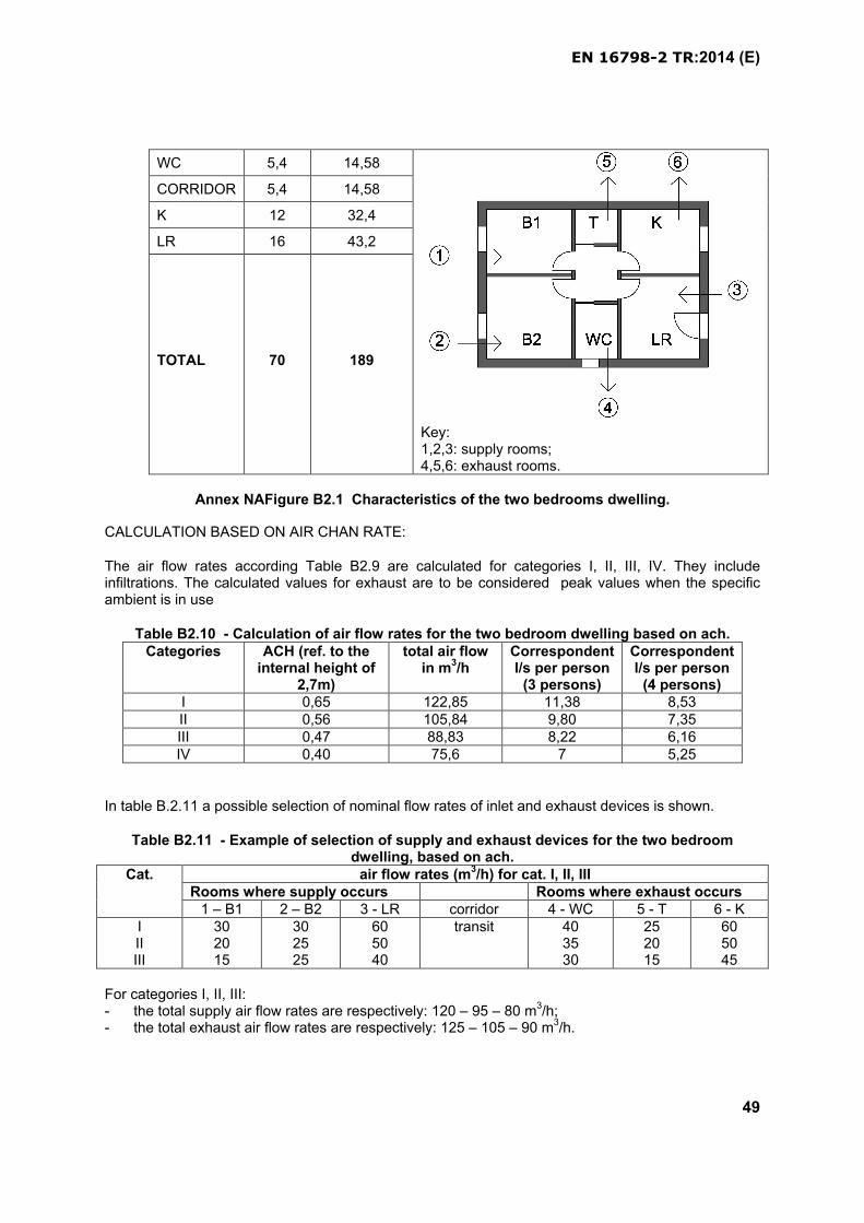
EN 16798-2 TR:2014 (E)
49
WC 5,4 14,58
Key:1,2,3: supply rooms;4,5,6: exhaust rooms.
CORRIDOR 5,4 14,58
K 12 32,4
LR 16 43,2
TOTAL 70 189
Annex NAFigure B2.1 Characteristics of the two bedrooms dwelling.
CALCULATION BASED ON AIR CHAN RATE:
The air flow rates according Table B2.9 are calculated for categories I, II, III, IV. They include infiltrations. The calculated values for exhaust are to be considered peak values when the specific ambient is in use
Table B2.10 - Calculation of air flow rates for the two bedroom dwelling based on ach.Categories ACH (ref. to the
internal height of 2,7m)
total air flow in m3/h
Correspondent l/s per person
(3 persons)
Correspondent l/s per person
(4 persons)I 0,65 122,85 11,38 8,53II 0,56 105,84 9,80 7,35III 0,47 88,83 8,22 6,16IV 0,40 75,6 7 5,25
In table B.2.11 a possible selection of nominal flow rates of inlet and exhaust devices is shown.
Table B2.11 - Example of selection of supply and exhaust devices for the two bedroom dwelling, based on ach.
Cat. air flow rates (m3/h) for cat. I, II, IIIRooms where supply occurs Rooms where exhaust occurs
1 – B1 2 – B2 3 - LR corridor 4 - WC 5 - T 6 - KIIIIII
302015
302525
605040
transit 403530
252015
605045
For categories I, II, III: - the total supply air flow rates are respectively: 120 – 95 – 80 m3/h;- the total exhaust air flow rates are respectively: 125 – 105 – 90 m3/h.
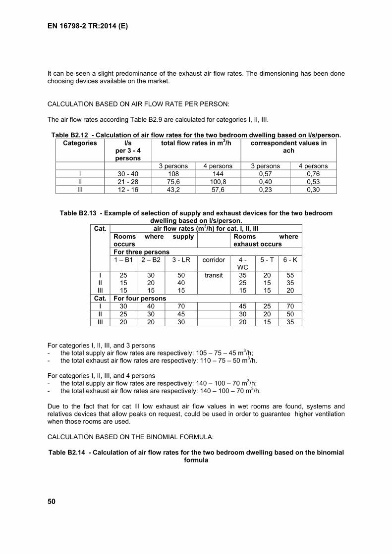
EN 16798-2 TR:2014 (E)
50
It can be seen a slight predominance of the exhaust air flow rates. The dimensioning has been done choosing devices available on the market.
CALCULATION BASED ON AIR FLOW RATE PER PERSON:
The air flow rates according Table B2.9 are calculated for categories I, II, III.
Table B2.12 - Calculation of air flow rates for the two bedroom dwelling based on l/s/person.Categories l/s
per 3 - 4 persons
total flow rates in m3/h correspondent values in ach
3 persons 4 persons 3 persons 4 personsI 30 - 40 108 144 0,57 0,76II 21 - 28 75,6 100,8 0,40 0,53III 12 - 16 43,2 57,6 0,23 0,30
Table B2.13 - Example of selection of supply and exhaust devices for the two bedroom dwelling based on l/s/person.
Cat. air flow rates (m3/h) for cat. I, II, IIIRooms where supply occurs
Rooms where exhaust occurs
For three persons1 – B1 2 – B2 3 - LR corridor 4 -
WC5 - T 6 - K
IIIIII
251515
302015
504015
transit 352515
201515
553520
Cat. For four personsI 30 40 70 45 25 70II 25 30 45 30 20 50III 20 20 30 20 15 35
For categories I, II, III, and 3 persons- the total supply air flow rates are respectively: 105 – 75 – 45 m3/h;- the total exhaust air flow rates are respectively: 110 – 75 – 50 m3/h.
For categories I, II, III, and 4 persons- the total supply air flow rates are respectively: 140 – 100 – 70 m3/h;- the total exhaust air flow rates are respectively: 140 – 100 – 70 m3/h.
Due to the fact that for cat III low exhaust air flow values in wet rooms are found, systems and relatives devices that allow peaks on request, could be used in order to guarantee higher ventilation when those rooms are used.
CALCULATION BASED ON THE BINOMIAL FORMULA:
Table B2.14 - Calculation of air flow rates for the two bedroom dwelling based on the binomial formula
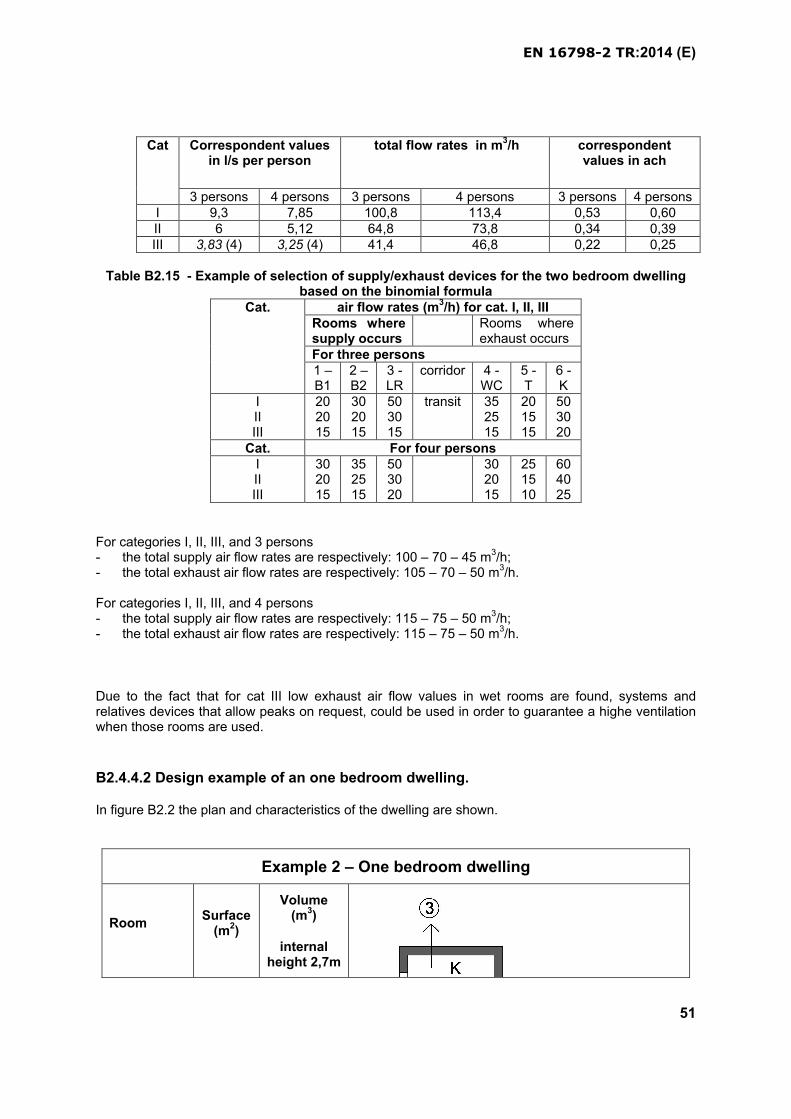
EN 16798-2 TR:2014 (E)
51
Cat Correspondent values in l/s per person
total flow rates in m3/h correspondent values in ach
3 persons 4 persons 3 persons 4 persons 3 persons 4 personsI 9,3 7,85 100,8 113,4 0,53 0,60II 6 5,12 64,8 73,8 0,34 0,39III 3,83 (4) 3,25 (4) 41,4 46,8 0,22 0,25
Table B2.15 - Example of selection of supply/exhaust devices for the two bedroom dwelling based on the binomial formula
Cat. air flow rates (m3/h) for cat. I, II, IIIRooms where supply occurs
Rooms where exhaust occurs
For three persons1 –B1
2 –B2
3 -LR
corridor 4 -WC
5 -T
6 -K
IIIIII
202015
302015
503015
transit 352515
201515
503020
Cat. For four personsIIIIII
302015
352515
503020
302015
251510
604025
For categories I, II, III, and 3 persons- the total supply air flow rates are respectively: 100 – 70 – 45 m3/h;- the total exhaust air flow rates are respectively: 105 – 70 – 50 m3/h.
For categories I, II, III, and 4 persons- the total supply air flow rates are respectively: 115 – 75 – 50 m3/h;- the total exhaust air flow rates are respectively: 115 – 75 – 50 m3/h.
Due to the fact that for cat III low exhaust air flow values in wet rooms are found, systems and relatives devices that allow peaks on request, could be used in order to guarantee a highe ventilation when those rooms are used.
B2.4.4.2 Design example of an one bedroom dwelling.
In figure B2.2 the plan and characteristics of the dwelling are shown.
Example 2 – One bedroom dwelling
RoomSurface
(m2)
Volume (m3)
internal height 2,7m
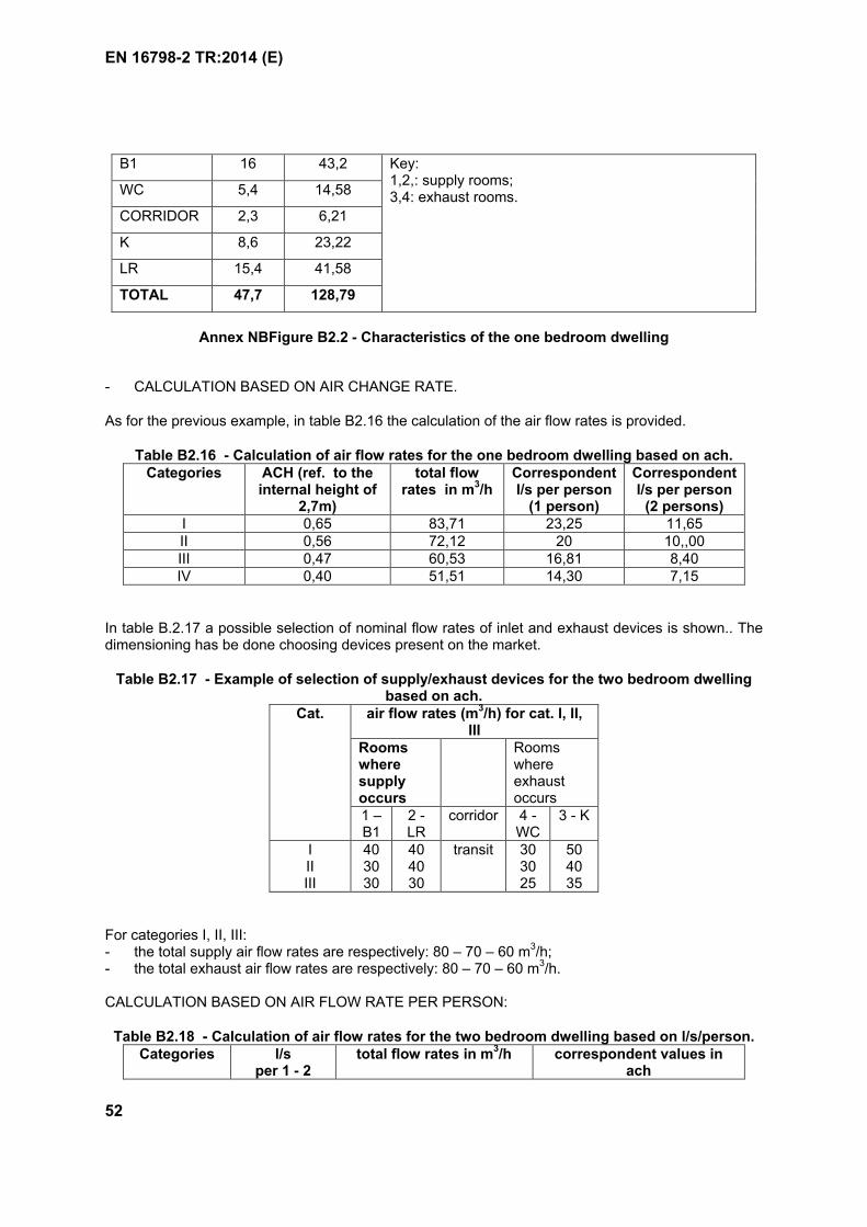
EN 16798-2 TR:2014 (E)
52
B1 16 43,2 Key:1,2,: supply rooms;3,4: exhaust rooms.WC 5,4 14,58
CORRIDOR 2,3 6,21
K 8,6 23,22
LR 15,4 41,58
TOTAL 47,7 128,79
Annex NBFigure B2.2 - Characteristics of the one bedroom dwelling
- CALCULATION BASED ON AIR CHANGE RATE.
As for the previous example, in table B2.16 the calculation of the air flow rates is provided.
Table B2.16 - Calculation of air flow rates for the one bedroom dwelling based on ach.Categories ACH (ref. to the
internal height of 2,7m)
total flow rates in m3/h
Correspondent l/s per person
(1 person)
Correspondent l/s per person
(2 persons)I 0,65 83,71 23,25 11,65II 0,56 72,12 20 10,,00III 0,47 60,53 16,81 8,40IV 0,40 51,51 14,30 7,15
In table B.2.17 a possible selection of nominal flow rates of inlet and exhaust devices is shown.. The dimensioning has be done choosing devices present on the market.
Table B2.17 - Example of selection of supply/exhaust devices for the two bedroom dwelling based on ach.
Cat. air flow rates (m3/h) for cat. I, II, III
Rooms where supply occurs
Rooms where exhaust occurs
1 –B1
2 -LR
corridor 4 -WC
3 - K
IIIIII
403030
404030
transit 303025
504035
For categories I, II, III: - the total supply air flow rates are respectively: 80 – 70 – 60 m3/h;- the total exhaust air flow rates are respectively: 80 – 70 – 60 m3/h.
CALCULATION BASED ON AIR FLOW RATE PER PERSON:
Table B2.18 - Calculation of air flow rates for the two bedroom dwelling based on l/s/person.Categories l/s
per 1 - 2 total flow rates in m3/h correspondent values in
ach
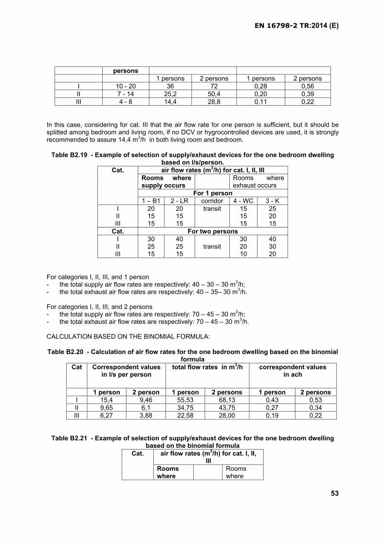
EN 16798-2 TR:2014 (E)
53
persons1 persons 2 persons 1 persons 2 persons
I 10 - 20 36 72 0,28 0,56II 7 - 14 25,2 50,4 0,20 0,39III 4 - 8 14,4 28,8 0,11 0,22
In this case, considering for cat. III that the air flow rate for one person is sufficient, but it should be splitted among bedroom and living room, if no DCV or hygrocontrolled devices are used, it is strongly recommended to assure 14,4 m3/h in both living room and bedroom.
Table B2.19 - Example of selection of supply/exhaust devices for the one bedroom dwelling based on l/s/person.
Cat. air flow rates (m3/h) for cat. I, II, IIIRooms where supply occurs
Rooms where exhaust occurs
For 1 person1 – B1 2 - LR corridor 4 - WC 3 - K
IIIIII
201515
201515
transit 151515
252015
Cat. For two personsIIIIII
302515
402515
transit302010
403020
For categories I, II, III, and 1 person- the total supply air flow rates are respectively: 40 – 30 – 30 m3/h;- the total exhaust air flow rates are respectively: 40 – 35– 30 m3/h.
For categories I, II, III, and 2 persons- the total supply air flow rates are respectively: 70 – 45 – 30 m3/h;- the total exhaust air flow rates are respectively: 70 – 45 – 30 m3/h.
CALCULATION BASED ON THE BINOMIAL FORMULA:
Table B2.20 - Calculation of air flow rates for the one bedroom dwelling based on the binomial formula
Cat Correspondent values in l/s per person
total flow rates in m3/h correspondent values in ach
1 person 2 person 1 person 2 persons 1 person 2 personsI 15,4 9,46 55,53 68,13 0,43 0,53II 9,65 6,1 34,75 43,75 0,27 0,34III 6,27 3,88 22,58 28,00 0,19 0,22
Table B2.21 - Example of selection of supply/exhaust devices for the one bedroom dwelling based on the binomial formula
Cat. air flow rates (m3/h) for cat. I, II, III
Rooms where
Rooms where
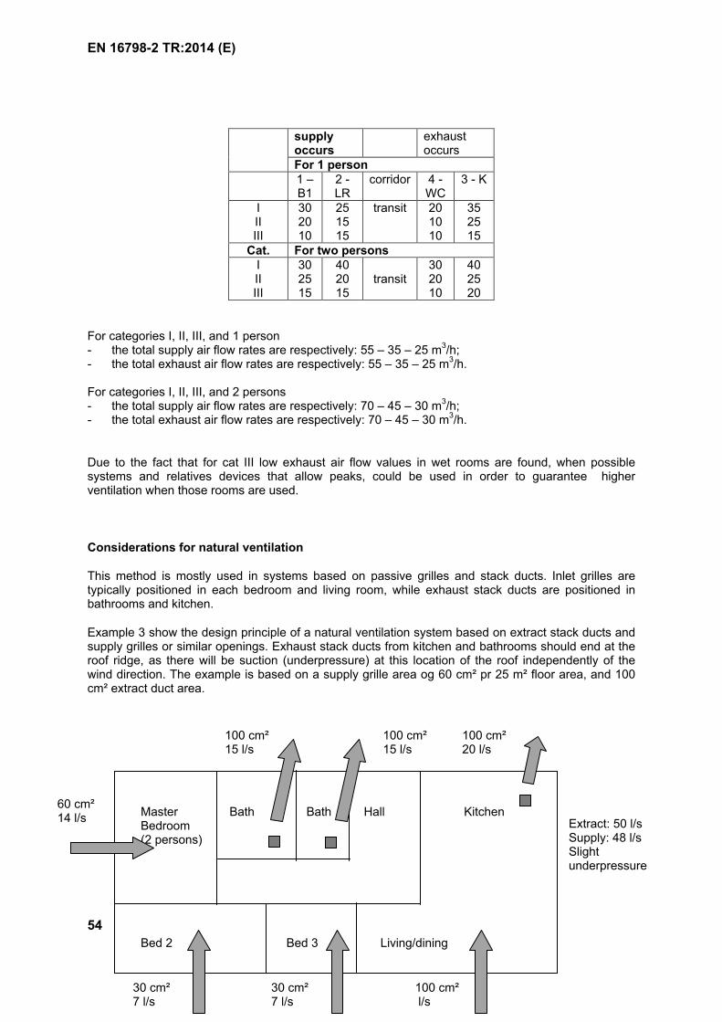
EN 16798-2 TR:2014 (E)
54
supply occurs
exhaust occurs
For 1 person1 –B1
2 -LR
corridor 4 -WC
3 - K
IIIIII
302010
251515
transit 201010
352515
Cat. For two personsIIIIII
302515
402015
transit302010
402520
For categories I, II, III, and 1 person- the total supply air flow rates are respectively: 55 – 35 – 25 m3/h;- the total exhaust air flow rates are respectively: 55 – 35 – 25 m3/h.
For categories I, II, III, and 2 persons- the total supply air flow rates are respectively: 70 – 45 – 30 m3/h;- the total exhaust air flow rates are respectively: 70 – 45 – 30 m3/h.
Due to the fact that for cat III low exhaust air flow values in wet rooms are found, when possible systems and relatives devices that allow peaks, could be used in order to guarantee higher ventilation when those rooms are used.
Considerations for natural ventilation
This method is mostly used in systems based on passive grilles and stack ducts. Inlet grilles are typically positioned in each bedroom and living room, while exhaust stack ducts are positioned in bathrooms and kitchen.
Example 3 show the design principle of a natural ventilation system based on extract stack ducts and supply grilles or similar openings. Exhaust stack ducts from kitchen and bathrooms should end at the roof ridge, as there will be suction (underpressure) at this location of the roof independently of the wind direction. The example is based on a supply grille area og 60 cm² pr 25 m² floor area, and 100 cm² extract duct area.
KitchenBath Bath HallMaster Bedroom (2 persons)
Bed 2 Bed 3 Living/dining
100 cm²20 l/s
100 cm²15 l/s
100 cm²15 l/s
60 cm²14 l/s
30 cm²7 l/s
30 cm²7 l/s
100 cm²l/s
Extract: 50 l/s Supply: 48 l/s Slight underpressure
EN 16798-2 TR:2014 (E)
55
Example 3 - Single-family house, constant air flow rate, cat II. Based on “Natural ventilation in single-family houses”, National Danish Building Research Institute, 1996.
B2.4.4.3 Comments on the above examples
With reference to the examples’ results, it is possible to describe some general principles according to the different ventilation technologies
Centralized systems (Exhaust ventilation and Balanced or double flux ventilation)Number and sizes of supply air inlets are chosen according values of column TOTAL SUPPLY and have to be installed in each main room (bedroom and living room); exhaust devices and duct’s sizes have to be chosen according to values of column TOTAL EXHAUST, because the system has to able to exhaust that air flows when needed (for example during peaks). During unoccupied periods supplyvalues can be lower (DCV) and even exhaust air flows can be smaller, balancing supply ones. During peak times in wet rooms a temporary unbalanced working for double flux systems is allowed.
Decentralized systems (supply ventilation room by room, balanced or double flux ventilation with heat recovery room by room) The sum of supply air flows by equipment in each main room has to respect values of column TOTAL SUPPLY. At the same time, in each wet room an exhaust device has to guarantee the extraction of an amount of air concerning values of TOTAL EXHAUST. If in main rooms decentralized systems are present, exhaust from wet rooms can be on request, that means during usage and after usage for a certain period (for example during usage and after 30 minutes): During this time the double flux devices will work temporarily unbalanced.
A minimum ventilation rate between 0,05 to 0,1 l/sm2 during non-occupied hours is recommended if no value is given at national level. In residential building, “unoccupied periods” means mainly periods when there is no demand
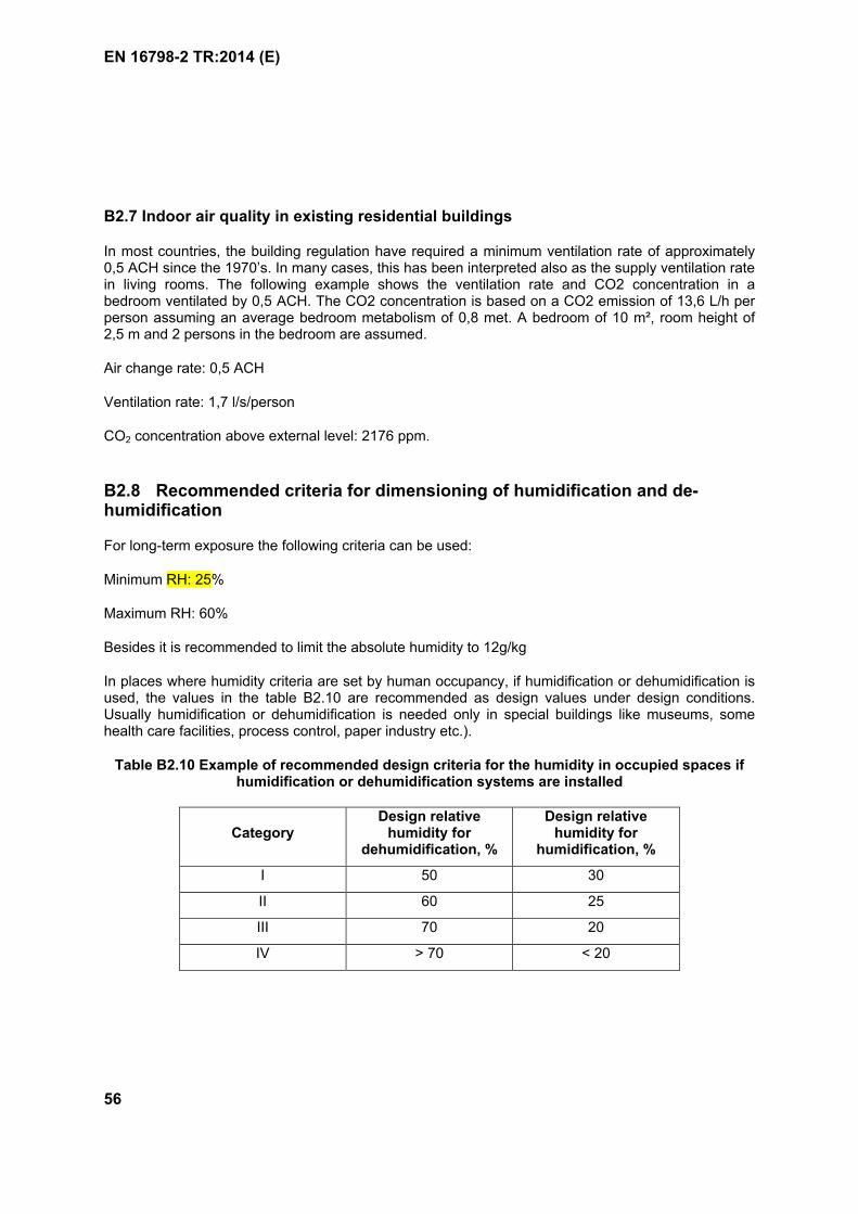
EN 16798-2 TR:2014 (E)
56
B2.7 Indoor air quality in existing residential buildings
In most countries, the building regulation have required a minimum ventilation rate of approximately 0,5 ACH since the 1970’s. In many cases, this has been interpreted also as the supply ventilation rate in living rooms. The following example shows the ventilation rate and CO2 concentration in a bedroom ventilated by 0,5 ACH. The CO2 concentration is based on a CO2 emission of 13,6 L/h per person assuming an average bedroom metabolism of 0,8 met. A bedroom of 10 m², room height of 2,5 m and 2 persons in the bedroom are assumed.
Air change rate: 0,5 ACH
Ventilation rate: 1,7 l/s/person
CO2 concentration above external level: 2176 ppm.
B2.8 Recommended criteria for dimensioning of humidification and de-humidification
For long-term exposure the following criteria can be used:
Minimum RH: 25%
Maximum RH: 60%
Besides it is recommended to limit the absolute humidity to 12g/kg
In places where humidity criteria are set by human occupancy, if humidification or dehumidification is used, the values in the table B2.10 are recommended as design values under design conditions. Usually humidification or dehumidification is needed only in special buildings like museums, some health care facilities, process control, paper industry etc.).
Table B2.10 Example of recommended design criteria for the humidity in occupied spaces if humidification or dehumidification systems are installed
CategoryDesign relative
humidity for dehumidification, %
Design relative humidity for
humidification, %
I 50 30
II 60 25
III 70 20
IV > 70 < 20
EN 16798-2 TR:2014 (E)
57
B2.9 Recommended ventilation during non-occupied hours.
Non-Residential buildings
External air flow equivalent to 2 air volumes of the ventilated space shall be delivered to the space before occupancy (e.g. if the ventilation rate is 2 ach the ventilation is started one hour before the occupancy). Infiltration can be calculated as a part of this ventilation (leakage assumptions should be described).
Instead of pre-start of the ventilation system, buildings to be ventilated during the unoccupied periods, with lower ventilation rate than during the occupied period. The minimum ventilation rate shall be defined based on building type and pollution load of the spaces. A minimum value of 0,1 to 0,2 l/s,m2
is recommended if national requirements are not available.
Residential buildings
In residential building, “non-occupied periods” means mainly periods when there is no demand.
A minimum ventilation rate between 0,05 to 0,1 l/sm2 during non-occupied hours is recommended if no value is given at national level
EN 16798-2 TR:2014 (E)
58
ANNEX B3(informative)
Example on how to define low and very low polluting buildings
Many interior construction and finishing products will emit pollutants into indoor air with the potential to deteriorate indoor air quality. Ventilation can flush out these emitted pollutants. Operating a building at low ventilation (as specified in this standard,) increases the risk of air pollution by these emitted substances and requires designing a building with low polluted interior spaces. This is done by selecting low emitting materials, especially for the large surfaces (walls, floors, ceilings). A simple way is to identify and select materials that are labeled to show conformity with legislative or voluntary specifications of low VOC emissions. The building is low or very low polluted if at least 80% of the interior materials are low or very low emitting.
Low or very low emitting materials are stone, glass, ceramics and non-treated metal, which are known to show no emissions into indoor air, and materials that show low or very low emissions (see table B3.1) when tested. Emissions properties are evaluated by testing the material after 28 days storage in a ventilated test chamber, in line with CEN/TS 16516 in combination with ISO 16000-11, or as specified in ISO 16000-3/-6/-9/-11. The emission rates obtained by this experiment then are transformed into air concentrations in the European Reference Room as specified in CEN/TS 16516, see table B3.2.
In countries with compulsory legal requirements, these are assumed to provide the minimum requirements (low emitting materials), while voluntary labels set the benchmark for very low emitting materials, see table B3.1. This holds true even for the French VOC regulation with different VOC emissions classes – even the most stringent legal VOC emissions class (A+) has less stringent requirements for most involved substances (except formaldehyde) than the voluntary labels specified. This allows a classification of VOC emissions on three levels (not low emitting, low emitting or very low emitting).
Therefore, low emitting products for low polluted buildings are those that respect legal requirements as e.g. in
Belgium France (VOC emissions class B or better)
(only the R value is not specified in that regulation) Germany (AgBB / DIBt)
The limits for very low emitting products for very low polluted buildings are based on a survey of the specifications of popular Eco labels for very low emitting products, such as
Blue Angel EMICODE EC1 GUT Indoor Air Comfort
Some other labels also are included in this approach, but these include even lower limit values: EMICODE EC1PLUS Indoor Air Comfort Gold M1
The approach is that it would not serve the purpose of this standard to refer only to the labels with the lowest limit values, but also to include labels with reasonably low limit values.
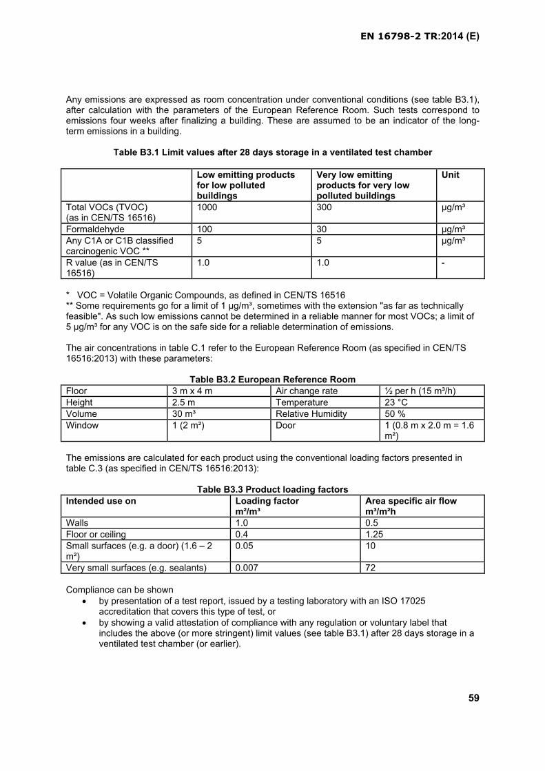
EN 16798-2 TR:2014 (E)
59
Any emissions are expressed as room concentration under conventional conditions (see table B3.1), after calculation with the parameters of the European Reference Room. Such tests correspond to emissions four weeks after finalizing a building. These are assumed to be an indicator of the long-term emissions in a building.
Table B3.1 Limit values after 28 days storage in a ventilated test chamber
Low emitting products for low polluted buildings
Very low emitting products for very low polluted buildings
Unit
Total VOCs (TVOC)(as in CEN/TS 16516)
1000 300 µg/m³
Formaldehyde 100 30 µg/m³Any C1A or C1B classified carcinogenic VOC **
5 5 µg/m³
R value (as in CEN/TS 16516)
1.0 1.0 -
* VOC = Volatile Organic Compounds, as defined in CEN/TS 16516** Some requirements go for a limit of 1 µg/m³, sometimes with the extension "as far as technically feasible". As such low emissions cannot be determined in a reliable manner for most VOCs; a limit of 5 µg/m³ for any VOC is on the safe side for a reliable determination of emissions.
The air concentrations in table C.1 refer to the European Reference Room (as specified in CEN/TS 16516:2013) with these parameters:
Table B3.2 European Reference RoomFloor 3 m x 4 m Air change rate ½ per h (15 m³/h)
Height 2.5 m Temperature 23 °CVolume 30 m³ Relative Humidity 50 %Window 1 (2 m²) Door 1 (0.8 m x 2.0 m = 1.6
m²)
The emissions are calculated for each product using the conventional loading factors presented in table C.3 (as specified in CEN/TS 16516:2013):
Table B3.3 Product loading factorsIntended use on Loading factor
m²/m³Area specific air flowm³/m²h
Walls 1.0 0.5
Floor or ceiling 0.4 1.25Small surfaces (e.g. a door) (1.6 – 2 m²)
0.05 10
Very small surfaces (e.g. sealants) 0.007 72
Compliance can be shown by presentation of a test report, issued by a testing laboratory with an ISO 17025
accreditation that covers this type of test, or by showing a valid attestation of compliance with any regulation or voluntary label that
includes the above (or more stringent) limit values (see table B3.1) after 28 days storage in a ventilated test chamber (or earlier).
EN 16798-2 TR:2014 (E)
60
An estimation of the air pollution of a real room will suffer from the facts that, even though this is possible as mathematical calculation, the once determined emissions will vary significantly in real life
over time, with high decrease of emission during the first days and weeks (the testing after 28 days storage in a ventilated test chamber is assumed to indicate somehow stable long-term emissions)
over production batches with differences and variations in temperature and relative humidity during installation of the
product and during operation of the building.
Therefore the selection of low emitting or very low emitting products only helps to achieve good indoor air quality by avoiding higher emitting products. Designing air quality precisely based on emissions data is not a realistic option for the above mentioned reasons. Nevertheless, if such estimation is foreseen, then the calculation follows cross-multiplication ("rule of three"):
cB = cR x LAB / LAR x ACR / ACB (B3.1)
where: cB is the mass concentration of compound a in the air of the actual building, in g/m3
cR is the mass concentration of compound a in the air of the reference room, in g/m3
LAB is the loading factor in the actual building, in square meter sample per cubic meter reference room;LAR is the loading factor in the reference room, in square meter sample per cubic meter reference room;ACR is the hourly air change rate in the reference room, in h-1
ACB is the hourly air change rate in the actual building, in h-1
Formula (B3.1) can be applied: to the maximum expected air concentrations, as given by the limit values if these are
respected, or to the actually detected emissions in the air of the reference room, if the above mentioned
limitations of such calculations are taken into account.
EN 16798-2 TR:2014 (E)
61
Annex B4(informative)
Examples of criteria for lighting
Table B.4.1 Examples of criteria for some buildings and spaces according to EN 12464.
Ref. no. acc. to EN 12464-1:2011
Type of area, task or activity
Ēm
lx
UGRL
–
Uo
–
Ra
– Specific requirements
5.26.2 Offices - Writing, typing, reading, data
processing
500 19 0,60 80 DSE-work, see 4.9
5.26.5 Offices - Conference and meeting rooms 500 19 0,60 80 Lighting should be controllable.
5.36.1 Educational buildings - Classrooms,
tutorial rooms
500 19 0,60 80 Lighting should be controllable.
5.36.2 Educational buildings - Classroom for
evening classes and adults education
500 19 0,60 80 Lighting should be controllable.
5.36.3 Educational buildings - Auditorium,
lecture halls
500 19 0,60 80 Lighting should be controllable to
accommodate various A/V needs.
5.39.1 Health care premises – Wards, maternity wards – General lighting
100 19 0,40 80
5.39.3 Health care premises – Wards, maternity wards – Simple examinations
300 19 0,40 80
5.40.1 Health care premises – Examination rooms (general) - General lighting
500 19 0,60 90 4 000 K ≤ TCP ≤ 5 000 K
5.40.2 Health care premises – Examination rooms (general) - Examination and
treatment
1000 19 0,7 90
5.29.3 Places of public assembly –Restaurants and hotels - Restaurant,
dining room, function room
-- -- -- -- The lighting should be designed
to create the appropriate
atmosphere.
5.36.24 Educational premises – Educational buildings - Sports halls, gymnasiums,
swimming pools
300 22 0,60 80 See EN 12193 for training
conditions.
5.27.1 Retail premises - Sales area 300 19 0,40 80
5.27.2 Retail premises - Till area 500 22 0,60 80
EN 16798-2 TR:2014 (E)
62
5.1.1 Traffic zones inside buildings -Circulation areas and corridors
100 28 0,40 40 Illuminance at floor level.
Ra and UGR similar to
adjacent areas.
150 lx if there are vehicles on
the route.
The lighting of exits and
entrances shall provide a
transition zone to avoid
sudden changes in
illuminance between inside
and outside by day or night.
Care should be taken to avoid
glare to drivers and pedestrians.
5.1.2 Traffic zones inside buildings - Stairs,
escalators, travelators
100 25 0,40 40 Requires enhanced contrast on
the steps.
EN 16798-2 TR:2014 (E)
63
ANNEX B5(informative)
Indoor system noise criteria of some spaces and buildings
Table B.5.1 Examples of design Sound Level, LmaxF, nT,A [dB(A)] for non-continuous sources
Building Sound Level, LmaxF, nT,A [dB(A)]I II III
Residences <32 <36 <40Hotels rooms <30 <34 <38Hospital patient room
<30 <34 <38
Offices <32 <36 <40
The sources considered are toilets, bathrooms, kitchen hoods etc.The values in this table refer to noise due to a source in a room or space different from the one considered
EN 16798-2 TR:2014 (E)
64
ANNEX C(informative)
Long term evaluation of the general thermal comfort conditions
To evaluate the comfort conditions over time (season, year) a summation of parameters must be made based on data measured in real buildings or dynamic computer simulations. This annex lists five methods, which can be used for that purpose.
Method A Percentage outside the range:
Calculate the number or % of occupied hours (those during which the building is occupied) when the PMV or the operative temperature is outside a specified range.
Method B Degree hours criteria:
The time during which the actual operative temperature exceeds the specified range during the occupied hours is weighted by a factor which is a function depending on by how many degrees, the range has been exceeded.
1. The weighing factor, wf, equals 0 for
Θo,limit,lower < Θo < Θo,limit,upper
where Θo,limit is the lower or upper limit of the comfort range specified (e.g. 23.0oC < Θo < 26.0oC corresponding to –0.5 < PMV < 0.5 as specified in Annex B1 for single offices, category A, summer).
2. The weighing factor, wf, is calculated as
wf = Θo - Θo,limit I
when Θo < Θo,limit,lower or Θo,limit,upper < Θo
3. For a characteristic period during a year, the product of the weighting factor and time is summed. The summation of the product has the unit of hours
Warm period:
wf time for Θo > Θo,limit,upper
Cold period:
wf time for Θo < Θo,limit,lower
Method C PPD weighted criteria:
The time during which the actual PMV exceeds the comfort boundaries is weighted by a factor which is a function of the PPD. Starting from a PMV-distribution on a yearly basis and the relation between PMV and PPD the following is calculated:
EN 16798-2 TR:2014 (E)
65
1 The weighing factor, wf, equals 0 for
PMVlimit,lower < PMV < PMVlimit,upper
Where PMVlimit is determined by the comfort range specified according to Annex B1.
2 The weighting factor, wf, is calculated as
PMVlimit
actualPMV
PPD
PPDwf
when
PMV < PMVlimit,lower or PMVlimit,upper < PMV
in which
PPDactualPMV = the PPD corresponding to the actual PMV
PPDPMVlimit = the PPD corresponding to PMVlimit
3 The product of the weighing factor and the time is summed for a characteristic working period during a year. The summation of the product has the unit of
Warm period:
wf time for PMV > PMVlimit,upper
Cold period:
wf time for PMV < PMVlimit,lower
Table C.1 illustrates this concept of method B and C. The weighting factors are based on temperature difference wf (°C) and PPD; wf (PPD) is shown for a comfort range of 23-26°C, corresponding tosedentary work (1.2 met) and light summer clothing (0.5 clo). For temperatures above or below this interval, the number of hours will be multiplied with these factors. It will be seen that using the PPD weighting factor will result in a higher number of hours. The values may be used for the evaluation of long-term comfort conditions.
Add PPD values in the table so that reader can follow how the weighting factor are calculated
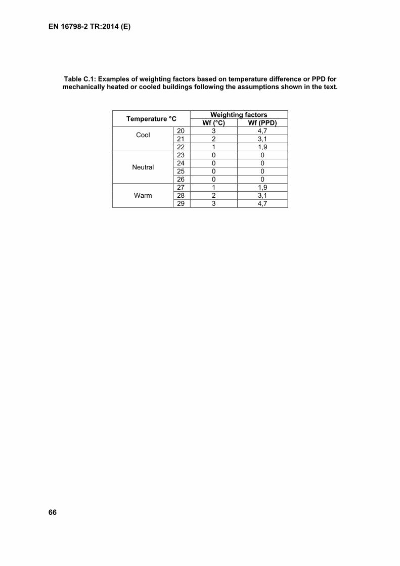
EN 16798-2 TR:2014 (E)
66
Table C.1: Examples of weighting factors based on temperature difference or PPD for mechanically heated or cooled buildings following the assumptions shown in the text.
Temperature °CWeighting factors
Wf (°C) Wf (PPD)
Cool20 3 4,721 2 3,122 1 1,9
Neutral
23 0 024 0 025 0 026 0 0
Warm27 1 1,928 2 3,129 3 4,7
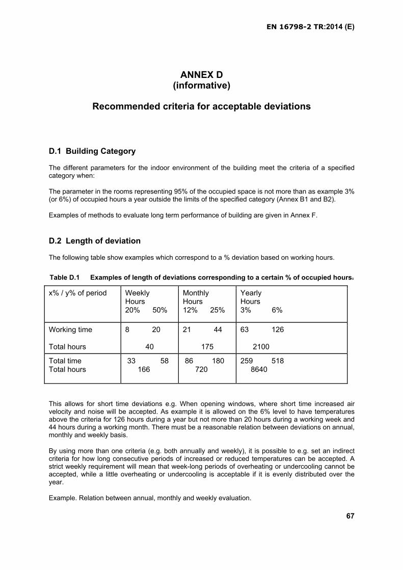
EN 16798-2 TR:2014 (E)
67
ANNEX D(informative)
Recommended criteria for acceptable deviations
D.1 Building Category
The different parameters for the indoor environment of the building meet the criteria of a specified category when:
The parameter in the rooms representing 95% of the occupied space is not more than as example 3% (or 6%) of occupied hours a year outside the limits of the specified category (Annex B1 and B2).
Examples of methods to evaluate long term performance of building are given in Annex F.
D.2 Length of deviation
The following table show examples which correspond to a % deviation based on working hours.
Table D.1 Examples of length of deviations corresponding to a certain % of occupied hours.
x% / y% of period WeeklyHours20% 50%
MonthlyHours12% 25%
YearlyHours3% 6%
Working time
Total hours
8 20
40
21 44
175
63 126 2100
Total timeTotal hours
33 58 166
86 180 720
259 518 8640
This allows for short time deviations e.g. When opening windows, where short time increased air velocity and noise will be accepted. As example it is allowed on the 6% level to have temperatures above the criteria for 126 hours during a year but not more than 20 hours during a working week and 44 hours during a working month. There must be a reasonable relation between deviations on annual, monthly and weekly basis.
By using more than one criteria (e.g. both annually and weekly), it is possible to e.g. set an indirect criteria for how long consecutive periods of increased or reduced temperatures can be accepted. A strict weekly requirement will mean that week-long periods of overheating or undercooling cannot be accepted, while a little overheating or undercooling is acceptable if it is evenly distributed over the year.
Example. Relation between annual, monthly and weekly evaluation.
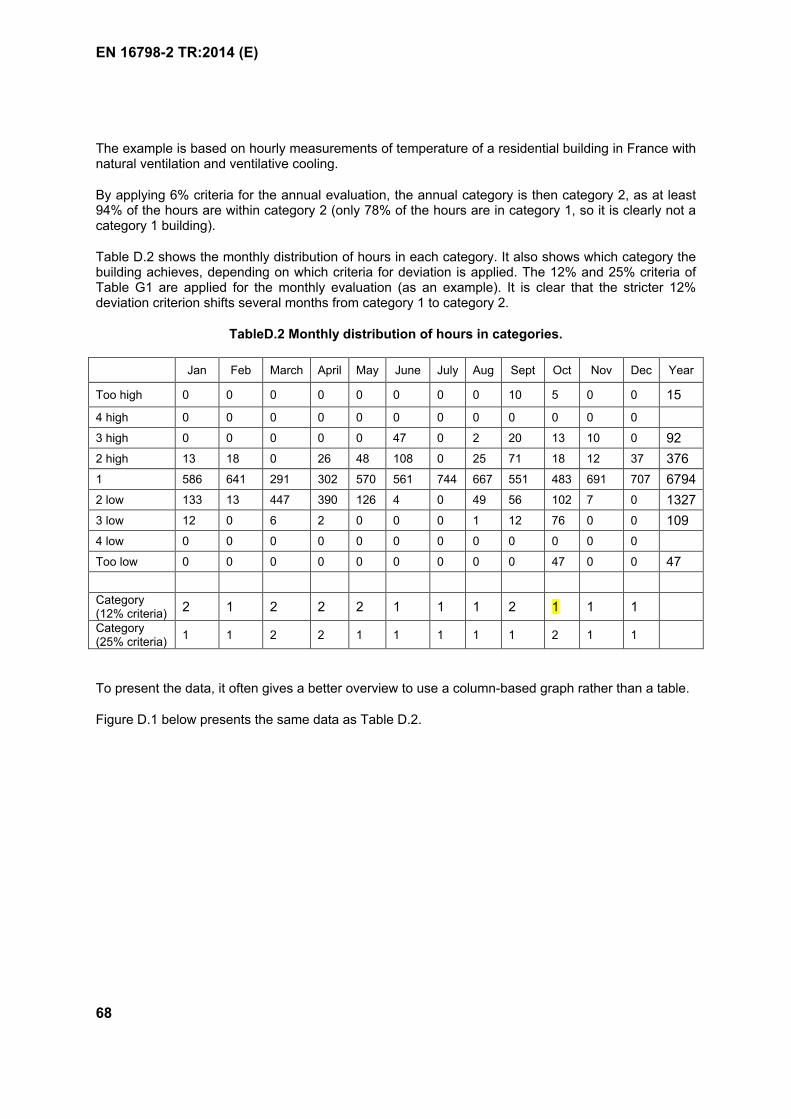
EN 16798-2 TR:2014 (E)
68
The example is based on hourly measurements of temperature of a residential building in France with natural ventilation and ventilative cooling.
By applying 6% criteria for the annual evaluation, the annual category is then category 2, as at least 94% of the hours are within category 2 (only 78% of the hours are in category 1, so it is clearly not a category 1 building).
Table D.2 shows the monthly distribution of hours in each category. It also shows which category the building achieves, depending on which criteria for deviation is applied. The 12% and 25% criteria of Table G1 are applied for the monthly evaluation (as an example). It is clear that the stricter 12% deviation criterion shifts several months from category 1 to category 2.
TableD.2 Monthly distribution of hours in categories.
Jan Feb March April May June July Aug Sept Oct Nov Dec Year
Too high 0 0 0 0 0 0 0 0 10 5 0 0 15
4 high 0 0 0 0 0 0 0 0 0 0 0 0
3 high 0 0 0 0 0 47 0 2 20 13 10 0 92
2 high 13 18 0 26 48 108 0 25 71 18 12 37 376
1 586 641 291 302 570 561 744 667 551 483 691 707 6794
2 low 133 13 447 390 126 4 0 49 56 102 7 0 1327
3 low 12 0 6 2 0 0 0 1 12 76 0 0 109
4 low 0 0 0 0 0 0 0 0 0 0 0 0
Too low 0 0 0 0 0 0 0 0 0 47 0 0 47
Category(12% criteria)
2 1 2 2 2 1 1 1 2 1 1 1
Category(25% criteria)
1 1 2 2 1 1 1 1 1 2 1 1
To present the data, it often gives a better overview to use a column-based graph rather than a table.
Figure D.1 below presents the same data as Table D.2.
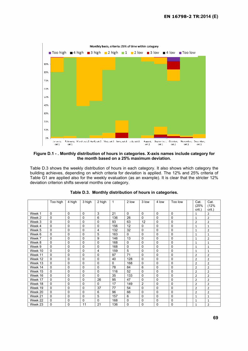
EN 16798-2 TR:2014 (E)
69
Figure D.1 - . Monthly distribution of hours in categories. X-axis names include category for the month based on a 25% maximum deviation.
Table D.3 shows the weekly distribution of hours in each category. It also shows which category the building achieves, depending on which criteria for deviation is applied. The 12% and 25% criteria of Table G1 are applied also for the weekly evaluation (as an example). It is clear that the stricter 12% deviation criterion shifts several months one category.
Table D.3. Monthly distribution of hours in categories.
Too high 4 high 3 high 2 high 1 2 low 3 low 4 low Too low Cat. (25% crit.)
Cat. (12% crit.)
Week 1 0 0 0 3 21 0 0 0 0 1 2Week 2 0 0 0 6 136 26 0 0 0 1 2Week 3 0 0 0 0 93 63 12 0 0 2 2Week 4 0 0 0 0 156 12 0 0 0 1 1Week 5 0 0 0 4 132 32 0 0 0 1 2Week 6 0 0 0 5 163 0 0 0 0 1 1Week 7 0 0 0 9 146 13 0 0 0 1 2Week 8 0 0 0 0 168 0 0 0 0 1 1Week 9 0 0 0 0 168 0 0 0 0 1 1Week 10 0 0 0 4 159 5 0 0 0 1 1Week 11 0 0 0 0 97 71 0 0 0 2 2Week 12 0 0 0 0 40 128 0 0 0 2 2Week 13 0 0 0 0 0 168 0 0 0 2 2Week 14 0 0 0 0 78 84 6 0 0 2 2Week 15 0 0 0 0 116 52 0 0 0 2 2Week 16 0 0 0 0 35 133 0 0 0 2 2Week 17 0 0 0 26 95 47 0 0 0 2 2Week 18 0 0 0 0 17 149 2 0 0 2 2Week 19 0 0 0 37 77 54 0 0 0 2 2Week 20 0 0 0 6 96 66 0 0 0 2 2Week 21 0 0 0 5 157 6 0 0 0 1 1Week 22 0 0 0 0 168 0 0 0 0 1 1Week 23 0 0 11 21 136 0 0 0 0 1 2
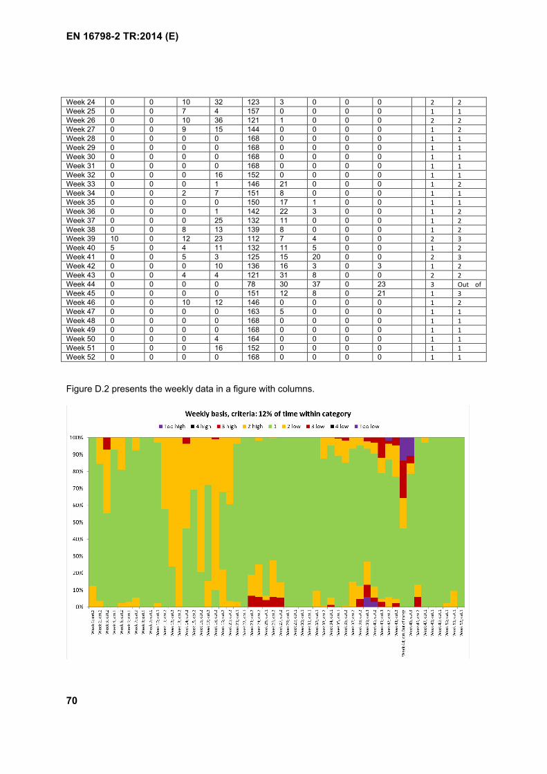
EN 16798-2 TR:2014 (E)
70
Week 24 0 0 10 32 123 3 0 0 0 2 2Week 25 0 0 7 4 157 0 0 0 0 1 1Week 26 0 0 10 36 121 1 0 0 0 2 2Week 27 0 0 9 15 144 0 0 0 0 1 2Week 28 0 0 0 0 168 0 0 0 0 1 1Week 29 0 0 0 0 168 0 0 0 0 1 1Week 30 0 0 0 0 168 0 0 0 0 1 1Week 31 0 0 0 0 168 0 0 0 0 1 1Week 32 0 0 0 16 152 0 0 0 0 1 1Week 33 0 0 0 1 146 21 0 0 0 1 2Week 34 0 0 2 7 151 8 0 0 0 1 1Week 35 0 0 0 0 150 17 1 0 0 1 1Week 36 0 0 0 1 142 22 3 0 0 1 2Week 37 0 0 0 25 132 11 0 0 0 1 2Week 38 0 0 8 13 139 8 0 0 0 1 2Week 39 10 0 12 23 112 7 4 0 0 2 3Week 40 5 0 4 11 132 11 5 0 0 1 2Week 41 0 0 5 3 125 15 20 0 0 2 3Week 42 0 0 0 10 136 16 3 0 3 1 2Week 43 0 0 4 4 121 31 8 0 0 2 2Week 44 0 0 0 0 78 30 37 0 23 3 Out of Week 45 0 0 0 0 151 12 8 0 21 1 3Week 46 0 0 10 12 146 0 0 0 0 1 2Week 47 0 0 0 0 163 5 0 0 0 1 1Week 48 0 0 0 0 168 0 0 0 0 1 1Week 49 0 0 0 0 168 0 0 0 0 1 1Week 50 0 0 0 4 164 0 0 0 0 1 1Week 51 0 0 0 16 152 0 0 0 0 1 1Week 52 0 0 0 0 168 0 0 0 0 1 1
Figure D.2 presents the weekly data in a figure with columns.
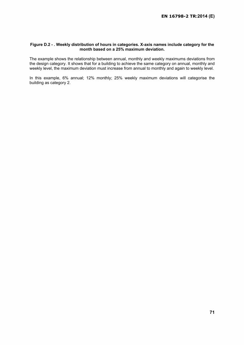
EN 16798-2 TR:2014 (E)
71
Figure D.2 - . Weekly distribution of hours in categories. X-axis names include category for the month based on a 25% maximum deviation.
The example shows the relationship between annual, monthly and weekly maximums deviations from the design category. It shows that for a building to achieve the same category on annual, monthly and weekly level, the maximum deviation must increase from annual to monthly and again to weekly level.
In this example, 6% annual; 12% monthly; 25% weekly maximum deviations will categorise the building as category 2.
EN 16798-2 TR:2014 (E)
72
ANNEX E(informative)
Methodologies for subjective evaluations
Subjective questionnaires can be used to evaluate the indoor environment. Subjective scales are presented to the occupants at fixed time intervals (daily, weekly, monthly, etc.). The scales can be presented through intranet on each person PC or handed out as hard copies. The questionnaires should be filled out during middle morning or middle afternoon. Not just after arrival or after a lunch break. The results can be presented as average values and/or distributions. See example in Annex I.
Do you want the room temperature?
a) Higher
b) No change
c) Lower
EN 16798-2 TR:2014 (E)
73
Figure E.1 Examples of questionnaires for subjective evaluations
EN 16798-2 TR:2014 (E)
74
ANNEX F(informative)
Examples of classification and certification of the indoor environment.
The indoor environment in a building may be classified by
a) Criteria used for energy calculations (new buildings)
b) Whole year computer simulations of the indoor environment and energy performance (new and existing buildings)
c) Long term measurement of selected parameters for the indoor environment (existing buildings)
d) Subjective responses from occupants (existing buildings)
F.1 The design criteria used
The classification is made by showing a table with criteria used for energy calculations as shown in the example in table F.1.
Table F.1 Classification based on criteria for energy calculations
Criteria of indoor environment Category of building Design Criteria
Thermal conditions in winter II 20-24 oC
Thermal conditions in summer III 22-27 oC
Air quality indicator, CO2 II 500 ppm above external
Ventilation rate II 1 l/sm2
Lighting Em > 500 lx; UGR<19; Ra>80
Acoustic environment Indoor noise <35 dB(A)
Noise from outdoors <55 dB(A)
EN 16798-2 TR:2014 (E)
75
F.2 Whole year computer simulations of the indoor environment and energy performance
By dynamic computer simulations it is possible for representative spaces in a building to calculate the space temperatures, ventilation rates and/or CO2 concentrations. It is then calculated how the temperatures are distributed between the 4 categories. This is done by a floor area weighted average for 95% of the building spaces. An example is shown in figure J1.
Figure F.1: Example of classification by “foot-print” of thermal environment and indoor air quality/ventilation. The distribution in the different categories is weighted by the floor area of
the different spaces in the building.
F.3 Long term measurement of selected parameters for the indoor environment
Parameters for the indoor environment like room temperature, ventilation rate and or CO2
concentrations is measured in representative spaces over a whole year or representative time period. The data are analysed in the same way as in section F.2 for calculated values, and presented in the same way (Figure F.1)
F.4 Subjective responses from occupants
By using all or some of the scales recommended in Annex I the occupants are asked to fill in the questionnaires at representative times during the year (winter-spring-summer-fall). The percentage of people voting acceptable (thermal environment and air quality) is calculated for each of the representative spaces in the buildings. A weighted average according to the number of people in the different spaces are calculated and used for classification. More details can also be included by showing the distribution of votes on the 7-point thermal sensation scale and showing the percentage of people wanting higher, no change and lower room temperature.
The results can be shown in a table like the example in table I2
Table B9.2 Examples of using the subjective reaction as classification of the indoor environment
Classification based on
occupants responses
Percentage
IIIIIIIVIndoor AirQuality
107677Percentage
IIIIIIIVThermal
Environment
206875Percentage
Quality of indoor environment in % of time in four categories
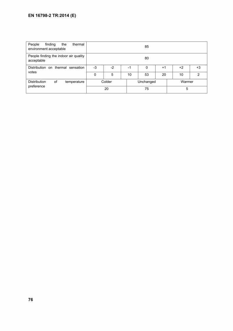
EN 16798-2 TR:2014 (E)
76
People finding the thermal
environment acceptable85
People finding the indoor air quality
acceptable80
Distribution on thermal sensation
votes
-3 -2 -1 0 +1 +2 +3
0 5 10 53 20 10 2
Distribution of temperature
preference
Colder Unchanged Warmer
20 75 5
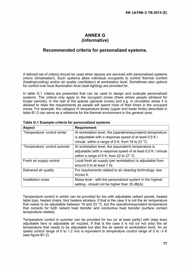
EN 16798-2 TR:2014 (E)
77
ANNEX G(informative)
Recommended criteria for personalized systems.
A tailored set of criteria should be used when spaces are serviced with personalized systems (micro climatisation). Such systems allow individual occupants to control thermal comfort(heating/cooling) and/or air quality (ventilation) at workstation level. Sometimes also options for control over local illumination level (task lighting) are provided for.
In table G.1 criteria are presented that can be used to design and evaluate personalized systems. The criteria only apply to the occupant zones (there where people sit/stand for longer periods). In the rest of the spaces (general zones) and e.g. in circulation areas it is allowed to relax the requirements as people will spend most of their times in the occupant zones. For example: the category III temperature levels (upper and lower limits) described in table B1.2 can serve as a reference for the thermal environment in the general zone.
Table G.1 Example criteria for personalized systems
Aspect Requirement
‘Temperature’ control winter At workstation level, the (operative/equivalent) temperature
is adjustable with a response speed of at least 0,5 K /
minute within a range of 5 K, from 18 to 23 °C.
‘Temperature’ control summer At workstation level, the (equivalent) temperature is
adjustable (with a response speed of at least 0,5 K / minute
within a range of 5 K, from 22 to 27 °C.
Fresh air supply control Local fresh air supply (per workstation) is adjustable from
around 0 to at least 7 l/s.
Delivered air quality For requirements related to air cleaning technology: see
Annex K.
Installation noise Noise level - with the personalized system in the highest
setting - should not be higher than 35 dB(A).
Temperature control in winter can be provided for too with adjustable radiant panels, heated table tops, heated chairs, foot heaters etcetera. If that is the case it is not the air temperature that needs to be adjustable between 18 and 23 °C, but the operative/equivalent temperature that corrects for both radiant heat transfer and conductive heat transfer (surface contact temperature related).
Temperature control in summer can be provided for too (or at least partly) with (step less) adjustable fans or adjustable air nozzles. If that is the case it is not (or not only) the air temperature that needs to be adjustable but also the air speed at workstation level. An air speed control range of 0 to 1.2 m/s is equivalent to temperature control range of 0 to -3 K (see figure B1.2).
EN 16798-2 TR:2014 (E)
78
The air quality in the breathing zone can be taken care of by personalized fresh air supply, by personalized air cleaning (a recirculation ventilation system that includes a personal filtration section) or by a combination of the two. For more details concerning air cleaning, see Annex H.
The ventilation part should be designed in such a way that pollution levels in the breathing zone are considerable lower than in the rest of the room air. This implies that the personal air diffuser and/or personalized air cleaner should generate an “air shower” effect in the immediate vicinity of the outlet of the unit.
The effective air supply in the breathing zone close to the mouth and nose of the occupantgenerally is much higher with personalized ventilation systems than with traditional room-based mixing systems. This depends largely upon the ventilation effectiveness of the type of system that is used.
The breathing zone ventilation V(b.z.) can be calculated with the following formula:
V(b.z.) = V(complete mixing) * e(v)
Where V(complete mixing) is the fresh air supply as mentioned in standard table xxx that assuming that a complete mixing systems is used; e(v) is the ventilation effectiveness.
The ventilation effectiveness of personalized ventilation systems generally lies in the range of 1,2 to 2,2 with a supply air temperature of 6 K below room temperature; in the range of 1,3 to 2,3 with a supply air temperature of 3 K below room temperature; and in the range of 1,6 to 3,5 with a supply air temperature equal as room temperature. Assuming an average ventilation effectiveness of 2, this implies that supplying 7 l/s fresh air via personalized ventilation systems creates the same air quality in the breathing zone as 14 l/s supplied via a room-based mixing ventilation system.
EN 16798-2 TR:2014 (E)
79
ANNEX H(informative)
Recommended methods for substitute ventilation air by air cleaning.
Air cleaning is not taken into account at all in prEN16798-1, while ASHRAE 62.1 by using the analytical procedure allows some credits for air cleaning. There is an increased interest in the development of air cleaning equipment. This may be an acceptable way of reducing the amount of outside air, saving energy and still have an acceptable indoor air quality. However, better test methods for air cleaners are required, because at present the test is usually based on chemical measurements and the resulting effect on odour or perceived air quality is not taken into account. It is also very important to specify which kind of “pollutants” should be used when testing. Some air cleaners may work well on particles, bio contaminants (microorganisms – pollens molds, allergens) and/or VOC’s (emission from materials or resulting from external air pollutants infiltration in the building such as PAH (Poly Aromatic Hydrocarbons)) but they may have zero or even a negative effect if the source is people (bio effluents).
VOCs may be adsorbed on the surface of particles acting as a vector. Therefore air cleaners combining particle and gas filtration technologies are interesting for reducing the amount of VOCs at the same time the particle matters are filtered.
There is an increasing development of methods and products for particle and gas phase air cleaning including both particle or adsorptions filters and air cleaners using a chemical reaction to remove certain gasses and pollutants (PCO-Photo Catalytic Oxidisation, Ionisation, UV technology…..). CEN-ISO and ASHRAE are developing standard test methods, which will measure the air cleaning efficiency or the equivalent amount of outside air called Clean Air Delivery Rate, CADR. One aspect of air cleaning technology used is the potential release in the indoor environment of chemical by products that can be harmful for occupants.AFNOR XPB44-200 standard for example requires to evaluate the level of CO, Formaldehyde, NO2, NO and Ozone, potential PCO reaction by products, as part of the testing procedure for portable air cleaners. Available information and compliance to the standard would have to be retrieved from air cleaner manufacturer technical information.
If we work with classes one option could be that even with air cleaning you must have a level of ventilation corresponding to the lowest class. With air cleaning you can then reach a higher class without increasing the amount of outside air. It is therefore recommended that the standard specifying indoor air quality as a certain ventilation rate open up for the possibility to partly use air cleaning as a supplement to outside air or a complementary function to take down PM matter and VOCs,.
One serious problem is how to ventilate if a building is located in an area with poor outside air quality or if there is a time of the day (e.g. rush hour) when the outside air quality is unacceptable. In some cases it might even be better to reduce ventilation under these circumstances and use a portable air cleaner to reduce indoor air pollutants, as dilution principle of ventilation is not applicable in that case.
When operating an air cleaning device, maintaining the unit’s efficiency when opening doors or windows as well as if particulates generated indoors increase, might be challenged and the expected performance not met since pollutants sources cannot be controlled.
EN 16798-2 TR:2014 (E)
80
For testing gas phase air cleaning known gases are used to simulate pollution (i.e. toluene, acetone… to simulate VOC’s). Particle matters air cleaning efficiency is tested against particle Aerosol and adapted from EN779 or EN1822 standards to evaluate particle air filters efficiency. Portable air cleaners recirculating the indoor air contribute to the reduction of existing allergens and microorganisms indoors. Same testing principle can be applied to evaluate the device efficiency against known allergens (e.g. cat allergens), bacteria and moulds aerosols.
The pollutants concentration is measured before and after the air cleaner. The air cleaning efficiency is calculated for each of the tested pollutants as:
εclean = (CU – CD)/CU·100 %
where: εclean air cleaning efficiencyCU gas concentration before air cleanerCD gas concentration after air cleaner
The criteria for the ventilation rates shown in Table B3 are mainly based on perceived air quality PAQ, which is measured by a human test panel. It is therefore also important to be able to test the air cleaning efficiency in relation to the perceived air quality. The air cleaning efficiency can be expressed as:
εPAQ =Qo/QAP·(PAQ/PAQAP-1)·100 %where:
εPAQ air cleaning efficiency for perceived air quality
Qo ventilations rate in l/s
QAP PAQ perceived air quality without the air cleaner, decipol
PAQAP perceived air quality without the air cleaner, decipol
The Clean Air Delivery Rate is calculated as:
CADR = εPAQ·QAP·(3,6/V) h-1 where: QAP· is the air flow through the air cleaner, in l/s
V is the volume of the room, in m3
If the air cleaner has been tested based on chemical measurements it should then be allowed to reduce the pollution contribution due to the building in Table 1 with a factor based on the measured air cleaning efficiency:
qb,clean = εclean·qb l/s per m2
If the efficiency is 50% the contribution from the building in Table 1 is then reduced to half, which means the building category can be changed from low-polluting to very low polluting.
For portable room air cleaner, energy use and noise are important aspects as well Therefore attention is to be paid to the noise level of the device in operation. The current ISO developed standard as well as existing AFNOR XPB44-200 define noise and energy consumption as additional criteria of air cleaner performance.
EN 16798-2 TR:2014 (E)
81
ANNEX I(informative)
WHO criteria for health in the indoor environment.
Scientific evidence of health impact of indoor air pollution, have lead WHO, European Commission and members states to define recommended guidelines or limit values for most harmful air pollutants.
Together with comfort criteria as humidity, odors, perception and CO2, air pollutants threshold levels indoors are also considered to define the indoor air quality level.
Table L1 gives suggested guideline values for indoor and external air pollutants formulated by WHO.
Table I.1 WHO guidelines values for indoor and external air pollutants.
Pollutant WHO IAQ guidelines 2011 WHO AQ guidelines 2005
Benzene No safe level
Carbon monoxide mg/m3
15 min 10030 min 601h 308h 1024h 7
15 min 10030 min 601h 308h 10
Formaldehyde µg/m3 30 minutes 100
Naphtalene µg/m3 Yearly 10
Nitrogene dioxide µg/m3 1h 200 1 year 40
1h 200 1 year 40
Polyaromatic Hydrocarbons PAHsBenzo Pyrene A B[a]P is the usual marker for PAHs
No threshold
Radon Bq/m3 100 reference level Shall be kept bellow 300
Trichlorethylene no safe level
Tetrachloroethylene µg/m3 Yearly 250
Sulfure dioxide SO2 µg/m3 10 min 50024H 20
Ozone O3 8 h 100
PM2,5 µg/m3 24h 251 Year 10
Particulate Matter PM10 µg/m3 24h 501 year 20
EN 16798-2 TR:2014 (E)
82
Air pollutants from external source impact air quality indoors. Their measurement provides valuable information to identify their source, levels and measures to be taken in order to control them. Air pollutant concentration evaluation after intervention allows to evaluate the result of the overall strategies implemented to improve indoor air quality.
WHO Air Quality Guidelines values may be considered as reference for Indoor air Quality when no other guideline or national recommendation for indoor air quality value exist in case of ambient air pollutants. Due to health effects confirmed at lower concentrations than current limit values and carcinogenic effect, the level of PAHs, particles, benzene should always be kept as low as possible. The applicable measures for controlling external air pollutants are described in section 6.2.3. EN13779 provides further guidance for the selection of appropriate air filters according to the building location and external air quality for mechanical ventilation systems.
In case of specific indoor pollution, ventilation rates shall be adapted to optimize the diluting effect of ventilation and additional air cleaning strategies can be considered.