Embed Size (px)
Citation preview
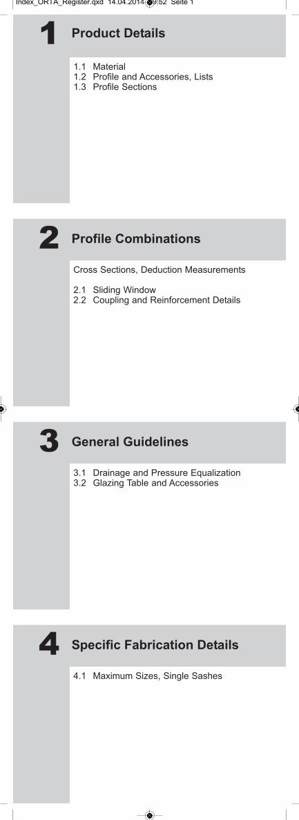
1 Product Details
1.1 Material1.2 Profile and Accessories, Lists1.3 Profile Sections
2 Profile Combinations
Cross Sections, Deduction Measurements
2.1 Sliding Window2.2 Coupling and Reinforcement Details
3 General Guidelines
3.1 Drainage and Pressure Equalization3.2 Glazing Table and Accessories
4 Specific Fabrication Details
4.1 Maximum Sizes, Single Sashes
Index_ORTA_Register.qxd 14.04.2014 09:52 Seite 1

ORTA
Product DetailsMaterial
Edition April 2014Technical information subject to change
Index
1.1
Page
1
The profiles are manufactured on extruders. Permanent production control safeguards thequality and geometrical precision of the profiles. The profiles fulfil the requirements underRAL-GZ 716/1, part 1.
profile material moulding compound, white as perDIN 7748 - PVC-U, EDLP, 080-35-28
density DIN EN ISO 1183 1.46 g/cm3
impact toughness up to -40 °C DIN 53453(small standard test piece) w/o fracture
notch toughness DIN EN ISO 179
(in standard atmosphere 23 °C
as per DIN EN ISO 179) (1fc test piece) ≥ 45 kJ/m2
ball hardness
(impression time 30 s) DIN ISO 239 T1 100 N/mm2
tensile strength DIN EN ISO 527 ≥ 40 N/mm2
modulus of elasticity DIN EN ISO 527 ≥ 2500 N/mm2
heat distortion temperature:
Vicat VST/B (measured in oil) DIN ISO 306 ≥ 80 °CISO R 75/A (measured in oil) DIN 53461 ≥ 69 °C
linear thermal expansion
coefficient -30 °C to +50 °C 0.8 x 10⁻⁴
K-1
Important note The observed changes in length experiencedby the heated profiles are minimal as demon-strated by numerous example installations. The mean change in length is: – 1.6 mm/m for white profiles – 2.4 mm/m for colour profiles
thermal conductivity DIN 52612 0.16 W/mK
volume resistivity DIN VBE 0303 T3 1016 Ω cm
relative permittivity DIN 53483 3.3 at 50 Hz;2.9 at 10 6 Hz
fire behaviour DIN 4102 flameresistant,self-extinguishing
weather resistance after 12 GJ/m2
RAL-GZ 716/1
insolation energy; discoloration no greater than resistance grade 3 of the grey scale according to ISO 105-A02
weather resistance after 12 GJ/m2
RAL-GZ 716/1
insolation energy; drop in notch toughness: < 30% or > 28 KJ/m2

ORTA
Product DetailsMaterial
Edition April 2014Technical information subject to change
Index
1.1
Page
2
particular resistances termite-proof, rot-proof, chemical-resistant as per DIN 8061 Bbl. 1, e.g. to: lyes, acids, salts, salt solu-tions, alkalis, seawater, petrol, oil, lime, cement,exhaust gases of all kinds
physiological propertiesand environmental behaviour inert, neutral
Its weather, chemical, and rot resistance ensure thatthey pose no risk to health or the environment whenhandled.
profile wall thickness as per RAL-GZ 716/1 Class B + C
machining operations drilling, milling, sawing, filing, welding, grinding
frame connection welded, screwed to mullion/transom
opening modes fixed glazing, side-hung, tilt/turn, bottom-hung, hinged,floating mullion, sliding/tilting drop windows, parallelsliding-tilting doors, balcony doorsWith the exception of parallel sliding-tilting doors allwindows and doors can be manufactured with roundor segmented arches.
glazing types dry glazing straight sash glazing rebate
pane types single insulating glass
glazing beads engaged over the whole length and easily replaceable
gaskets glazing gasket of EPDM or TPE
gasket colour black and light grey (RAL 7035)
fittings commercially available, according to KÖMMERLINGhardware list
chamber size see installation instructions for fittings
hardware fasteners screws
sash stop single
drainage drilled or elongated holes near the rebate;slots in drainage antechamber are downward or to thefront
sealing flexible between wall and outer frame
flush-mounted basic frame not necessary
installation in building façade all usual installation types possible
profile shapes as per workbook
surfaces white
paint finish possible (not necessary)
ORTA
Product DetailsMaterial
Edition April 2014Technical information subject to change
Index
1.1
Page
3
cleaning and care Köraclean extra (colour white), Köraclean color (tex-tured), water and suitable household cleaner (non-abrasive, non-dissolving). We cannot accept liability forall household cleaners. Do not use any cleaning orpolishing agents that dissolve PVC.
heat transfer coefficients – window insulation value (Uw): depends on theinstalled glazing and the profile’s U value
– glazing insulation value (Ug): approx 2.6–0.5 W/(m2 K)
reinforcements All main profiles can be reinforced with steel profilesin accordance with the design requirements.DIN EN 10.142/10.147/DX 51D+Z,cold-rolled as per DIN 59413/17118 orDIN EN 10.142/10.147, galvanised as per DVV 7Tables 4a + 4b

ORTA
Product DetailsProfiles and Accessoires, List
Edition April 2014
Technical information subject to change
Index
1.2
Page
1
Art. No. Function
P1660 Frame
2161 Frame
2178 Frame
2165 Adapter for frame
2170 Sash
2172 Sash
P1671 Flying screen sash
P1679 Flying screen sash
P1999 Screen track
A002 Butt profile
2171 Cover profile
A011 Aluminium guide rail
M149 Sealing bridge for P2161
M036 Sealing bridge for P2165
F9D37 End Cap for L9G37
F9D79 Edge connector for Sliding Shoe
A003 Alu interlook
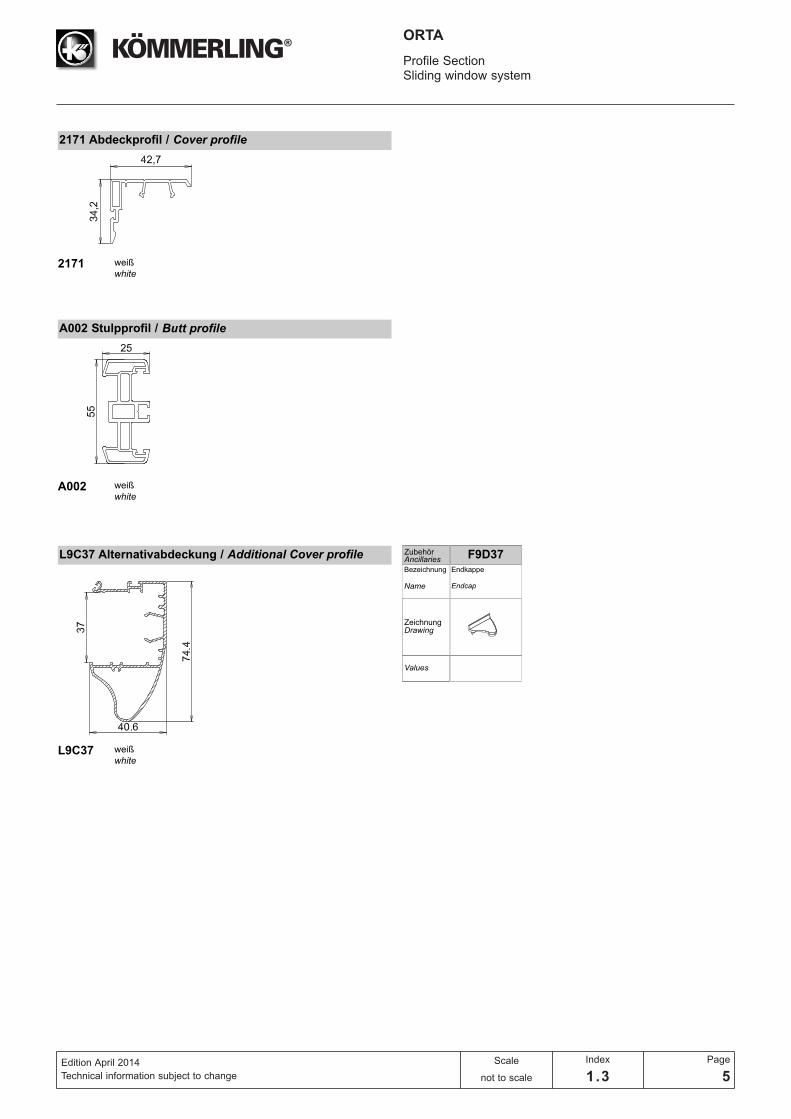
L9C37 Additional cover profile
Steel No. I value (cm4) Trickness (mm) Profile
V230 Iw= 1.1 1.5 P2161/P2178
V231 Iw= 1.0 1.5 P2170
V232 Iw= 1.9 2.0 P2172
V233 Iw= 0.7 1.5 P2165
V238 Iw= 0.4 1.5 P2178
G9363 Iw= 3.6 2.0 P1660
G9362.1 Iw= 2.8 1.5 P1660
G1679 Iw= 0.6 1.5 P1679

ORTA
Edition April 2014
Technical information subject to change
Index
1.2
Page
2
Product DetailsGlazing Accessoires List
Art. No. Function
P1680 Glazing bead 6 mm
P1681 Glazing bead 21.5 mm
P1982 Glazing bead 16.5 mm
M4524 Fin seal
G028 Fin seal
M9D39 Glazing gasket for 2170/2172
M9095 Round gasket
M9040 Weather seal

ORTA
Edition April 2014
Technical information subject to change
Index
1.2
Page
3
Product DetailsSecondary Profiles List
Art. No. Function
P0481 Coupling profile
P0442 Coupling profile
P1674 90° Corner profile
P1675 90° Corner profile
P1338 Static coupling profile
P1996 Round coupling
P1973 Adapter for 58 mm profile
P1988 Extension profile
B8124 Board profile
P1677 Coupling profile
P1248 Frame connector
F0002 Glass packer
F0003 Glass packer
F0005 Glass packer
F7448 Clip holder
Steel No. I value (cm4) Trickness (mm) Profile
G9704 Iw= 18.8 2.0 P0442
V143 Iw= 13.8 2.0 P0442
V144 Iw= 7.0 2.0 P0442
G1674 Iw= 5.5 2.0 P1674
G9108 Iw= 14.4 2.0 P1674
G9120 Iw= 10.0 2.0 P1674/P1338
V123 Iw= 11.7 2.0 P1996

ORTA
Profile SectionSliding window system
Edition April 2014
Technical information subject to change
Scale
not to scale
Index
1.3
Page
1
■ Erfolgreiches horizontales Schiebesystem in China und
anderen asiatischen Märkten
■ 3 Rahmenprofile sind erhältlich um jede Anfrage zu
bedienen
■ Glatter Innen falz für schnelle und effektive Entwässerung
■ Glasleiste mit anextrudierter Dichlippe, für schönere Optik
und leichte Reinigung.
■ Insektenschutz innen oder außen anbringbar
■ Wahlweise Fenster oder Türflügel machen das System
ökonomischer.
■ Bleifreie Calzium-Zink Rezeptur
System Highlights System highlights
■ A very successful horizontal sliding system in China andother Asian countries
■ 3 frames are available from 1 system to meet variousdemand
■ Slope rebate of frame assist to drain out water quickly■ Co-extruded sash and glazing bead with lips makes the
tight sealant and easy-working on assembly■ Provision of Mosquito net either interior or exterior■ System comprises of both Window and Door sash making
the system more economic■ Lead free - Calcium-Zink formulation

ORTA
Profile SectionSliding window system
Edition April 2014
Technical information subject to change
Scale
not to scale
Index
1.3
Page
2
DichtungssystemSeals system
EPDM DichtungenEPDM Seals
Z
Z
X
Y Y
X
Y
YX
Y Y Y Y
Y
X X

ORTA
Profile SectionSliding window system
Edition April 2014
Technical information subject to change
Scale
not to scale
Index
1.3
Page
3
2178 Rahmenprofil 49 mm / Frame profile
2178 weiß
white
ZeichnungDrawing
Bezeichnung
Values
ZubehörAncillaries
Name
IW = 1.1 cm4
IG = 0.1 cm4
Verstärkung
V230
Reinforcement
IW = 0.4 cm4
IG = 0.2 cm4
Verstärkung
V238
Reinforcement
Laufschiene
A011
Guide rail
2161 Rahmenprofil 49 mm / Frame profile
2161 weiß
white
ZeichnungDrawing
Bezeichnung
Values
ZubehörAncillaries
Name
IW = 1.1 cm4
IG = 0.1 cm4
Verstärkung
V230
Reinforcement
Dichtbrücke
M149
sealing bridge
Dichtbrücke
M149
sealing bridge
2165 Rahmenadapter 49 mm / frame adaptor
2165 weiß
white
ZeichnungDrawing
Bezeichnung
Values
ZubehörAncillaries
Name
IW = 0.7 cm4
IG = 0.3 cm4
Verstärkung
V233
Reinforcement
Dichtbrücke
M036
sealing bridge
P1660 Rahmenprofil 57 mm / Frame profile
P1660 weiß
white
ZeichnungDrawing
Bezeichnung
Values
ZubehörAncillaries
Name
IW = 3.6 cm4
IG = 1.0 cm4
Verstärkung
G9363
Reinforcement
IW = 2.8 cm4
IG = 0.8 cm4
Verstärkung
G9362.1
Reinforcement
Laufschiene
A011
Guide rail
Laufschiene
A011
Guide rail
Klippshalter
F7448
Clip holder
ORTA
Profile SectionSliding window system
Edition April 2014
Technical information subject to change
Scale
not to scale
Index
1.3
Page
4
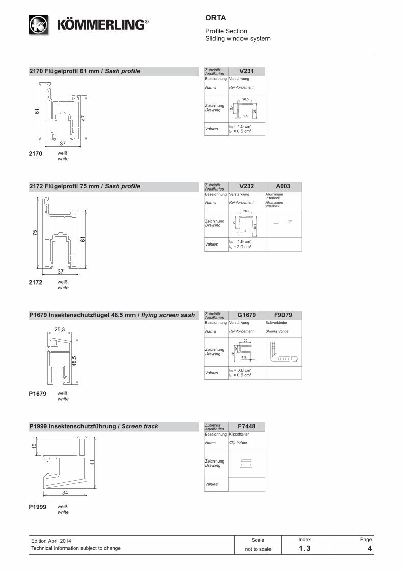
2170 Flügelprofil 61 mm / Sash profile
2170 weiß
white
ZeichnungDrawing
Bezeichnung
Values
ZubehörAncillaries
Name
IW = 1.0 cm4
IG = 0.5 cm4
Verstärkung
V231
Reinforcement
2172 Flügelprofil 75 mm / Sash profile
2172 weiß
white
ZeichnungDrawing
Bezeichnung
Values
ZubehörAncillaries
Name
IW = 1.9 cm4
IG = 2.0 cm4
Verstärkung
V232
Reinforcement
Aluminium Interlock
A003
Aluminium interlock
P1679 Insektenschutzflügel 48.5 mm / flying screen sash
P1999 Insektenschutzführung / Screen track
P1679 weiß
white
P1999 weiß
white
ZeichnungDrawing
Bezeichnung
Values
ZubehörAncillaries
Name
ZeichnungDrawing
Bezeichnung
Values
ZubehörAncillaries
Name
IW = 0.6 cm4
IG = 0.5 cm4
Verstärkung
G1679
Reinforcement
Eckverbinder
F9D79
Sliding Schoe
Klippshalter
F7448
Clip holder
ORTA
Profile SectionSliding window system
Edition April 2014
Technical information subject to change
Scale
not to scale
Index
1.3
Page
5
ORTA
Profile SectionSliding window system
Edition April 2014
Technical information subject to change
Scale
not to scale
Index
1.3
Page
6
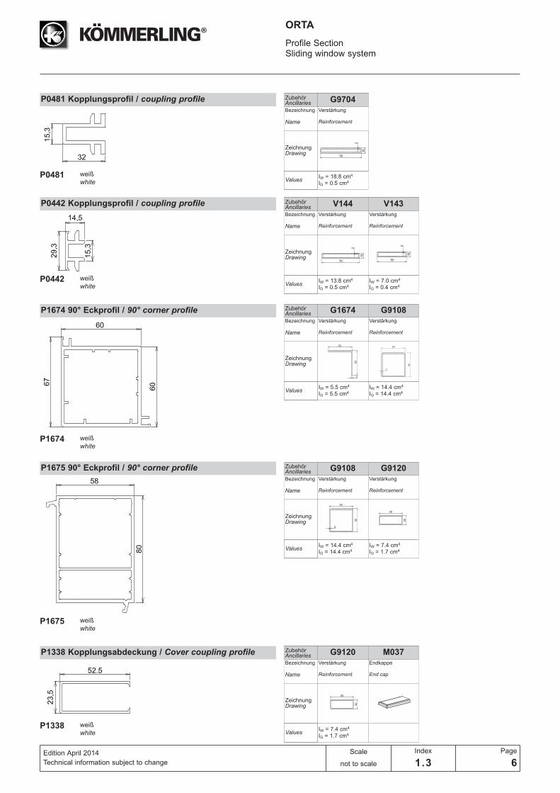
P0481 Kopplungsprofil / coupling profile
P0481 weiß
white
ZeichnungDrawing
Bezeichnung
Values
ZubehörAncillaries
Name
IW = 18.8 cm4
IG = 0.5 cm4
Verstärkung
G9704
Reinforcement
P0442 Kopplungsprofil / coupling profile
P0442 weiß
white
ZeichnungDrawing
Bezeichnung
Values
ZubehörAncillaries
Name
IW = 13.8 cm4
IG = 0.5 cm4
Verstärkung
V144
Reinforcement
IW = 7.0 cm4
IG = 0.4 cm4
Verstärkung
V143
Reinforcement
P1674 90° Eckprofil / 90° corner profile
P1674 weiß
white
ZeichnungDrawing
Bezeichnung
Values
ZubehörAncillaries
Name
IW = 5.5 cm4
IG = 5.5 cm4
Verstärkung
G1674
Reinforcement
P1675 90° Eckprofil / 90° corner profile
P1675 weiß
white
ZeichnungDrawing
Bezeichnung
Values
ZubehörAncillaries
Name
IW = 14.4 cm4
IG = 14.4 cm4
Verstärkung
G9108
Reinforcement
IW = 14.4 cm4
IG = 14.4 cm4
Verstärkung
G9108
Reinforcement
IW = 7.4 cm4
IG = 1.7 cm4
Verstärkung
G9120
Reinforcement
P1338 Kopplungsabdeckung / Cover coupling profile
P1338 weiß
white
ZeichnungDrawing
Bezeichnung
Values
ZubehörAncillaries
Name
IW = 7.4 cm4
IG = 1.7 cm4
Verstärkung
G9120
Reinforcement
Endkappe
M037
End cap
ORTA
Profile SectionSliding window system
Edition April 2014
Technical information subject to change
Scale
not to scale
Index
1.3
Page
7
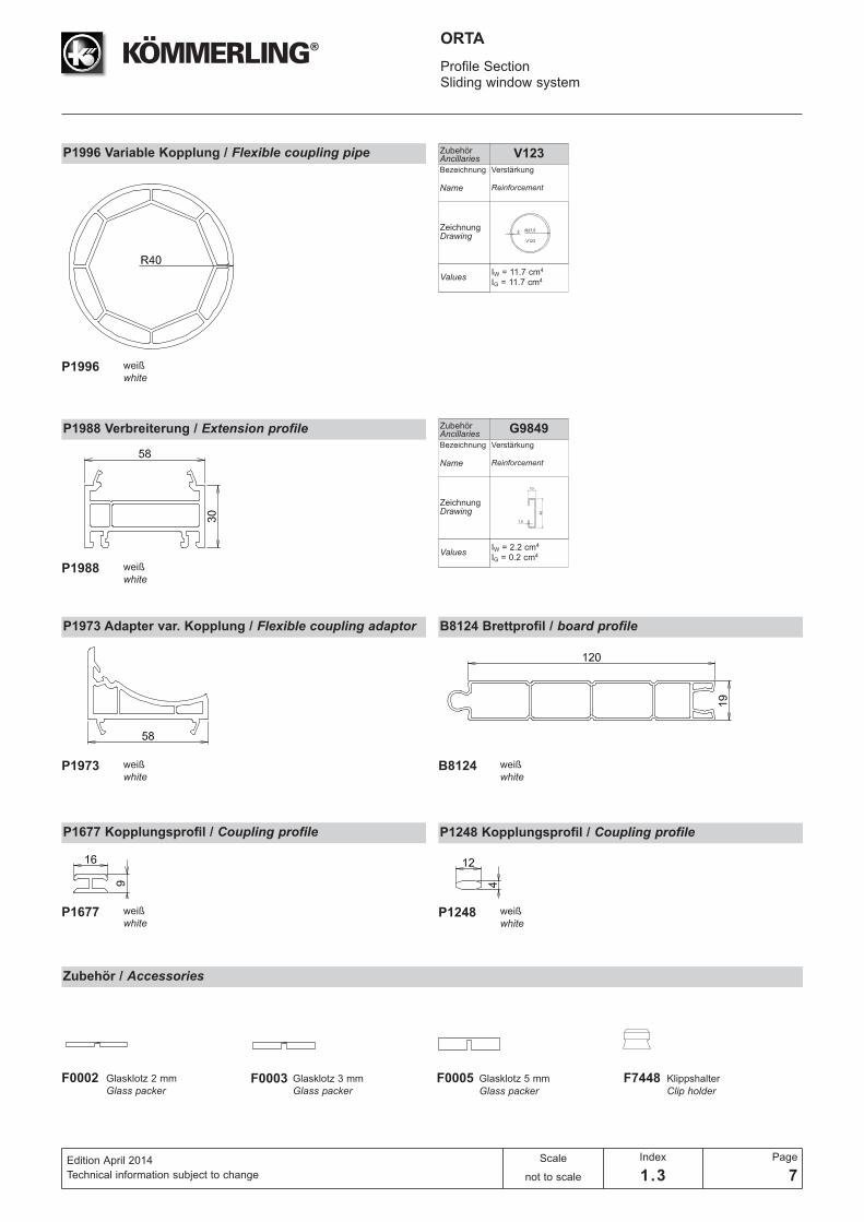
P1996 Variable Kopplung / Flexible coupling pipe
P1996 weiß
white
ZeichnungDrawing
Bezeichnung
Values
ZubehörAncillaries
Name
IW = 11.7 cm4
IG = 11.7 cm4
Verstärkung
V123
Reinforcement
ZeichnungDrawing
Bezeichnung
Values
ZubehörAncillaries
Name
IW = 2.2 cm4
IG = 0.2 cm4
Verstärkung
G9849
Reinforcement
P1973 Adapter var. Kopplung / Flexible coupling adaptor
P1973 weiß
white
P1988 Verbreiterung / Extension profile
P1988 weiß
white
B8124 Brettprofil / board profile
B8124 weiß
white
P1677 Kopplungsprofil / Coupling profile
P1677 weiß
white
P1248 Kopplungsprofil / Coupling profile
P1248 weiß
white
Zubehör / Accessories
F0002 Glasklotz 2 mm
Glass packerF0003 F0005 F7448Glasklotz 3 mm
Glass packerGlasklotz 5 mm
Glass packerKlippshalter
Clip holder
ORTA
Profile SectionSliding window system
Edition April 2014
Technical information subject to change
Scale
1:1
Index
1.3
Page
8
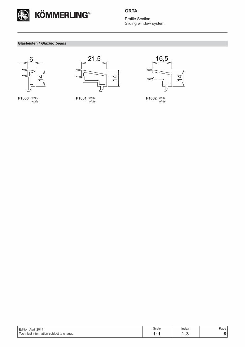
Glasleisten / Glazing beads
P1680 weiß
white P1681 weiß
white P1682 weiß
white

12,2
14
916,2
12
4
18
8 13
16,2
30,5
41
12 4
61
12,2
61
26
841
Deduction MeasurementsSliding Windows
Edition April 2014
Technical information subject to change
Scale
1:1
Index
2.1
Page
1
ORTA
Dimensions for window roller
Dimensions for window hardware
Dimensions for window roller and hardware
2170 2170
V231
2170
V231
2161
V230
2161
V230
V231
A011 A011M4574
M4574
M4574

21,512,2
33,5
816,516,2
41
4
12
75
25,5
12,2
8 20,5
16,2
41
43,8
12 4
75
Deduction MeasurementsSliding Doors
Edition April 2014
Technical information subject to change
Scale
1:1
Index
2.1
Page
2
ORTA
Dimensions for door roller
Dimensions for door hardware
Dimensions for door roller and hardware
2172 2172
V232
2172
V232
2161
V230
2161
V230
V232
A011 A011M4574
M4574
M4574
16
42,7
12
16,7
16
42,7
12
16,7 16
5512
19,5
16
55
12
19,5
L =
H -
82
L =
H -
82
Deduction MeasurementsSliding Windows and Doors
Edition April 2014
Technical information subject to change
Scale
1:1
Index
2.1
Page
3
ORTA
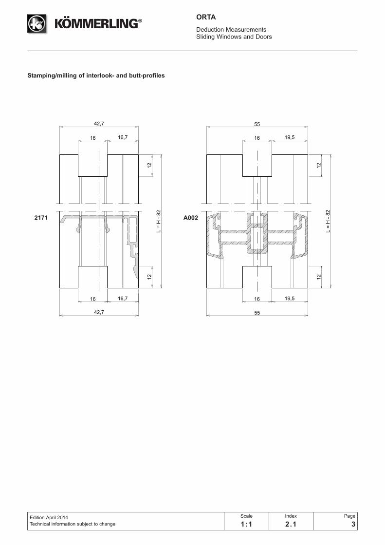
Stamping/milling of interlook- and butt-profiles
2171 A002
34
12,5
8
8
8
8
8
18,5
18,5
12,5 12,5
4,5 4,5
21,5
32,532,5
28,5
52,5 52,5
1/2
1/2
1/2
1/2
28,5
39,539,5
35,5
52,5 52,5
61
75
Deduction MeasurementsSliding Windows and Doors
Edition April 2014
Technical information subject to change
Scale
1:2
Index
2.1
Page
4
ORTA
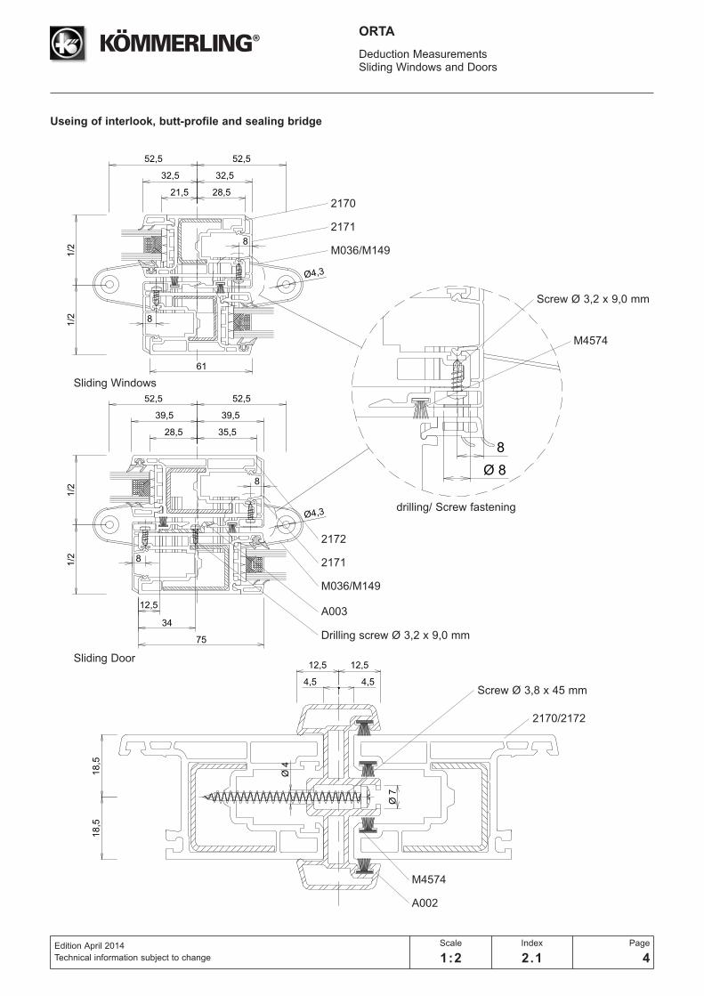
Useing of interlook, butt-profile and sealing bridge
drilling/ Screw fastening
M4574
Screw Ø 3,2 x 9,0 mm
Sliding Windows
Sliding Door
2170
2171
M036/M149
2172
2171
M4574
A002
2170/2172
A003
M036/M149
Drilling screw Ø 3,2 x 9,0 mm
Screw Ø 3,8 x 45 mm
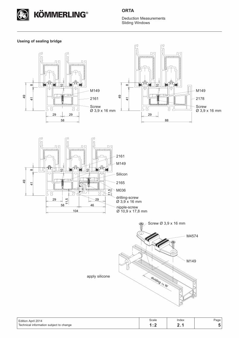
dividing 1/x W
108
414
9
29 29
58
108
414
9
29
88
108
414
9
29
58
11,5 29
46
104
10
11,5
Deduction MeasurementsSliding Windows
Edition April 2014
Technical information subject to change
Scale
1:2
Index
2.1
Page
5
ORTA
Screw Ø 3,9 x 16 mm
apply silicone
Useing of sealing bridge
M149
2161
Screw Ø 3,9 x 16 mm
M149
2161
M036
Silicon
2165
M149
M4574
drilling-screw Ø 3,9 x 16 mm
nipple-screw Ø 10,9 x 17,8 mm
M149
2178
Screw Ø 3,9 x 16 mm
58
H
W
H S1 S2
A
A
12,5
83
49
91 1
02
49
91
102
41
41
Deduction MeasurementsSliding Windows
Edition April 2014
Technical information subject to change
Scale
1:2
Index
2.1
Page
6
ORTA
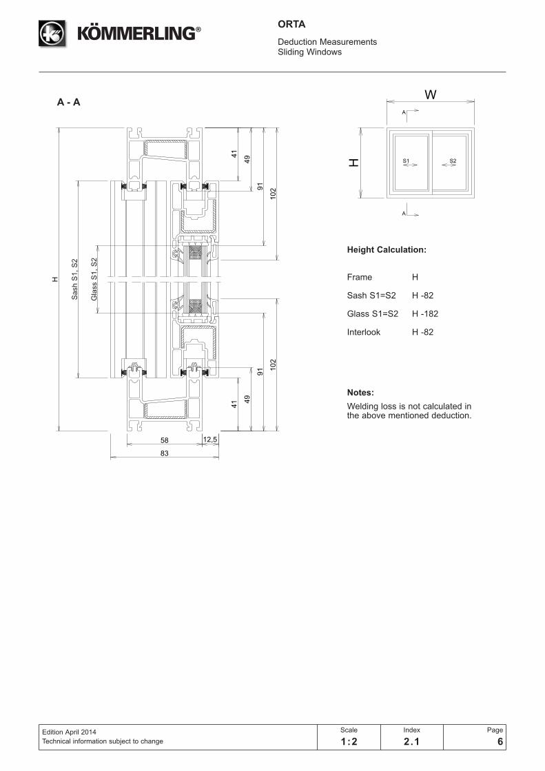
Height Calculation:
Frame H
Sash S1=S2 H -82
Glass S1=S2 H -182
Interlook H -82
Notes:
Welding loss is not calculated in the above mentioned deduction.
A - A
Sash S
1,
S2
Gla
ss S
1,
S2
49
58
W
W
H B BS1 S2
91 1
02
21,5
28,5
32,5
32,5
65
12,5
83
8
8
49
91
102
41
41
Deduction MeasurementsSliding Windows
Edition April 2014
Technical information subject to change
Scale
1:2
Index
2.1
Page
7
ORTA
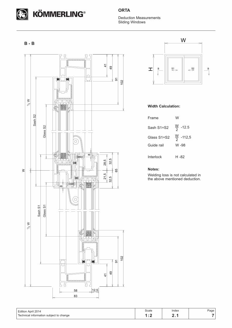
Width Calculation:
Frame W
Sash S1=S2
Glass S1=S2
Guide rail W -98
Interlock H -82
Notes:
Welding loss is not calculated in the above mentioned deduction.
W2
-12.5
W2
-112,5
B - B
1/ 2
W1/ 2
W
Sash S
2
Gla
ss S
2G
lass S
1
Sash S
1
W
H
C C
S1 S3
S2
W
58
21,5
28,5
32,5
32,5
65
21,5
28,5
32,5
32,5
65
49
91 1
02
12,5
83
8
88
8
49
91
102
41
41
Deduction MeasurementsSliding Windows
Edition April 2014
Technical information subject to change
Scale
1:2
Index
2.1
Page
8
ORTA
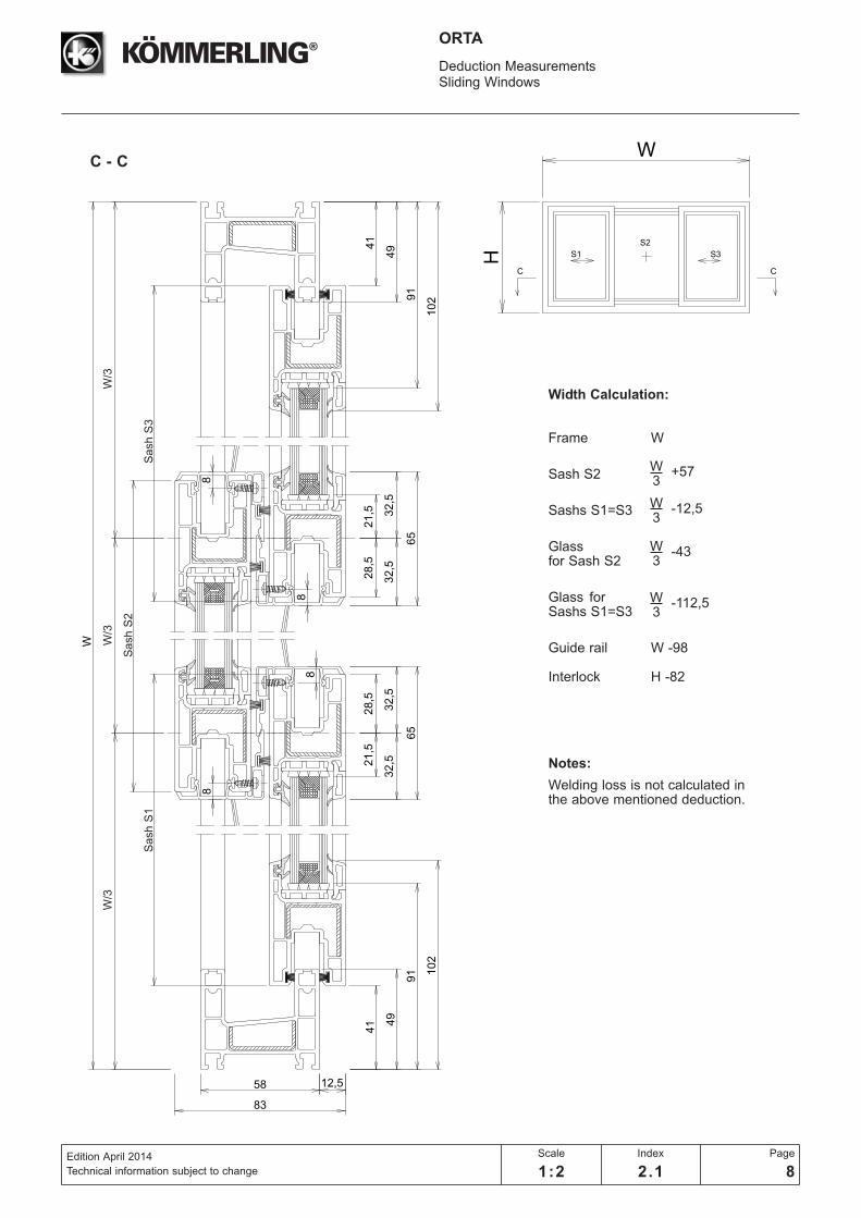
Width Calculation:
Frame W
Sash S2
Sashs S1=S3
Glassfor Sash S2
Glass for Sashs S1=S3
Guide rail W -98
Interlock H -82
Notes:
Welding loss is not calculated in the above mentioned deduction.
W3
+57
W3
-112,5
W3
-43
W3
-12,5
C - C
W/3
W/3
W/3
Sash S
2
Sash S
3S
ash S
1
W
H D DS3 S4S1 S2
Deduction MeasurementsSliding Windows
Edition April 2014
Technical information subject to changenot to scale
Index
2.1
Page
9
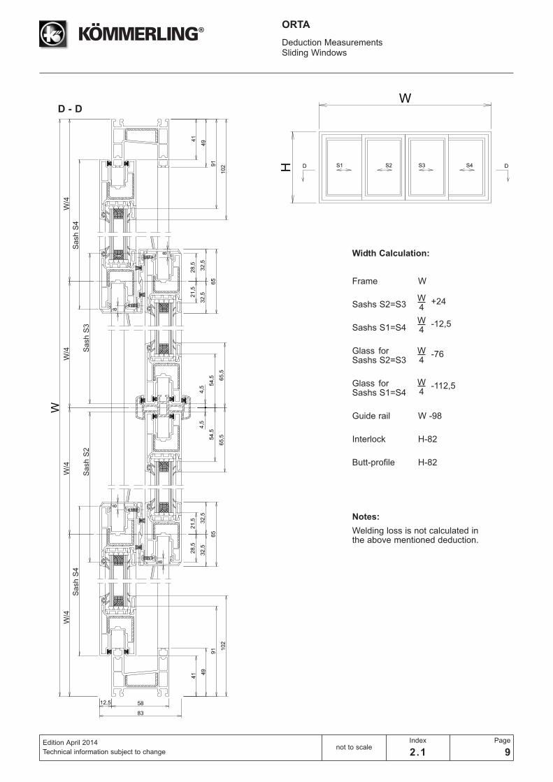
ORTA
Width Calculation:
Frame W
Sashs S2=S3
Sashs S1=S4
Glass for Sashs S2=S3
Glass for Sashs S1=S4
Guide rail W -98
Interlock H-82
Butt-profile H-82
Notes:
Welding loss is not calculated in the above mentioned deduction.
W4
+24
W4
-112,5
W4
-76
W4
-12,5
D - D
W/4
W/4
W/4
Sash S
3
Sash S
4
Sash S
2
W/4
Sash S
4

W
H B BS1 S2
58
W
49
105 116
12,5
83
28,5
35,5
39,5
39,5
79
34
12,5
8
8
41
49
105
116
41
Deduction MeasurementsSliding Doors
Edition April 2014
Technical information subject to change
Scale
1:2
Index
2.1
Page
10
ORTA
Width Calculation:
Frame W
Sash S1=S2
Glass for SashS1=S2
Guide rail W -98
Interlock H -82
Alu-Interlock H -82
Notes:
Welding loss is not calculated in the above mentioned deduction.
B - B
W2
-5,5
W2
-133,5
W/2
Sash S
2
Gla
ss S
2G
lass S
1
W/2
Sash S
1
58
W
34
12
,5
28
,53
5,5
39
,53
9,5
79
28
,53
5,5
39
,53
9,5
79
34
12
,5
49
10
5 11
6
12,5
83
8
88
8
49
10
5
11
6
41
41
W
H
C C
S1 S3
S2
Deduction MeasurementsSliding Doors
Edition April 2014
Technical information subject to changenot to scale
Index
2.1
Page
11
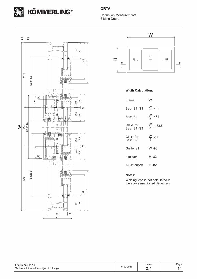
ORTA
Width Calculation:
Frame W
Sash S1=S3
Sash S2
Glass for Sash S1=S3
Glass for Sash S2
Guide rail W -98
Interlock H -82
Alu-Interlock H -82
Notes:
Welding loss is not calculated in the above mentioned deduction.
W3
-5,5
W3
-57
W3
-133,5
W3
+71
C - C
W/3
W/3
Sash S
3
Sash S
2
W/3 Sash S
1
58
W
49
10
5 11
6
12,5
92
28
,53
5,5
39
,53
9,5
79
28
,53
5,5
39
,53
9,5
79
4,5
68
,56
8,5
79
,57
9,5
8
88
8
12
,5
34
12
,5
34
49
10
5
11
6
4,5
41
41
W
H D DS3 S4S1 S2
Deduction MeasurementsSliding Doors
Edition April 2014
Technical information subject to changenot to scale
Index
2.1
Page
12
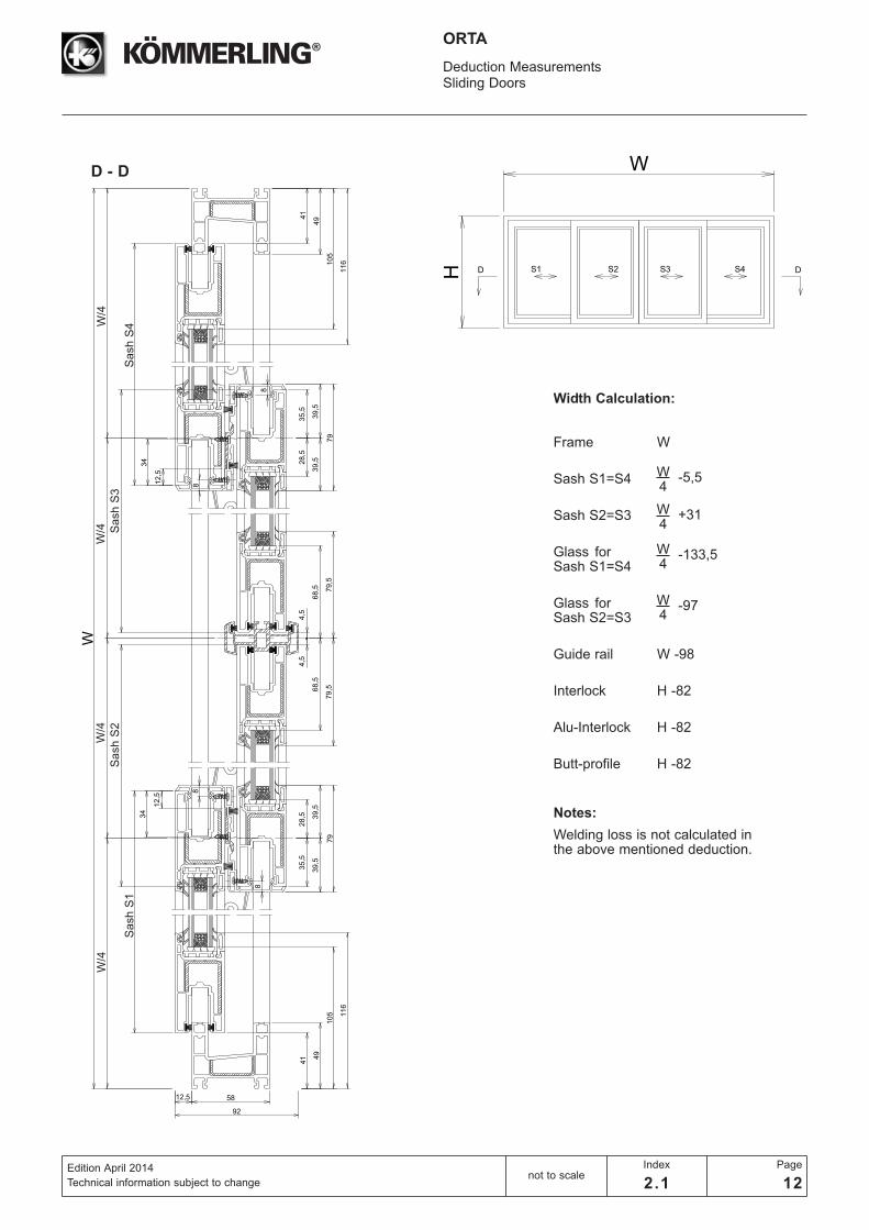
ORTA
Notes:
Welding loss is not calculated in the above mentioned deduction.
D - D
Width Calculation:
Frame W
Sash S1=S4
Sash S2=S3
Glass for Sash S1=S4
Glass for Sash S2=S3
Guide rail W -98
Interlock H -82
Alu-Interlock H -82
Butt-profile H -82
W4
-5,5
W4
-97
W4
-133,5
W4
+31
W/4
Sash S
4
W/4
Sash S
1
W/4 S
ash S
3
W/4
Sash S
2
88
H
W
H S1 S2
A
A
49
91 1
02
100,5
45
41
49
91
102
4541
Deduction MeasurementsSliding Windows
Edition April 2014
Technical information subject to change
Scale
1:2
Index
2.1
Page
13
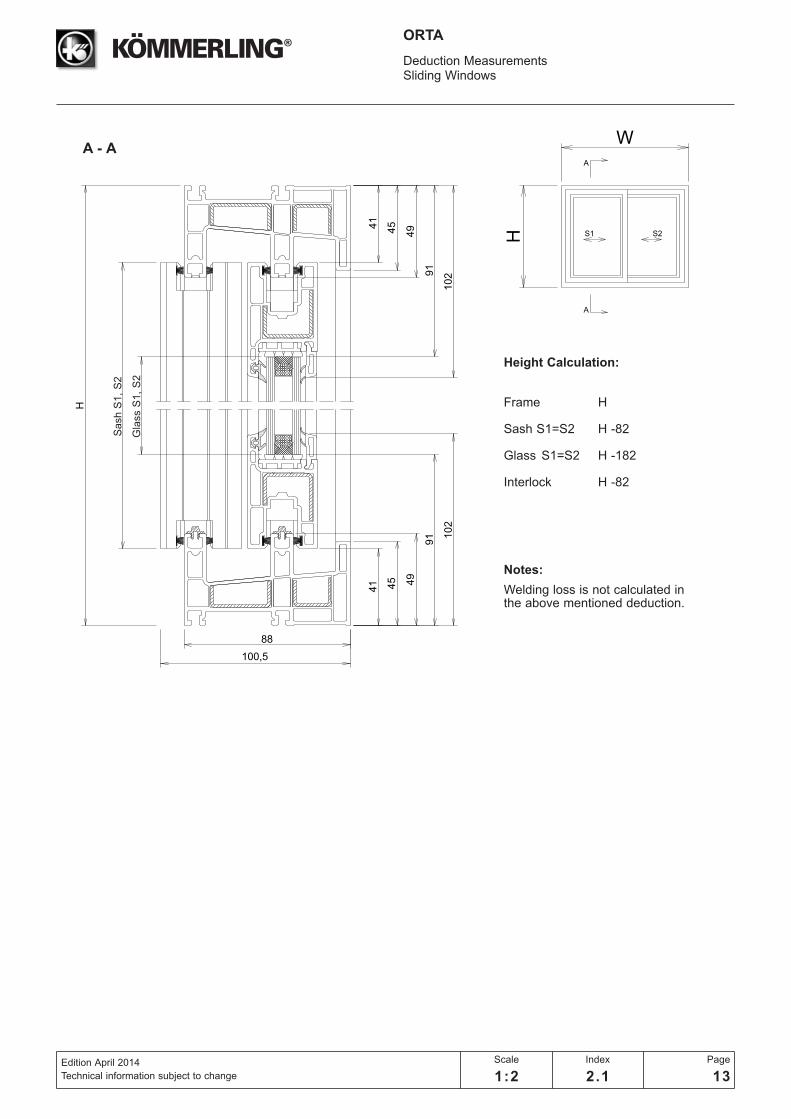
ORTA
Height Calculation:
Frame H
Sash S1=S2 H -82
Glass S1=S2 H -182
Interlock H -82
Notes:
Welding loss is not calculated in the above mentioned deduction.
A - A
Sash S
1,
S2
Gla
ss S
1,
S2
88
W
W
H B BS1 S2
49
91 1
02
21,5
28,5
32,5
32,5
65
100,5
8
8
45
41
49
91
102
4541
Deduction MeasurementsSliding Windows
Edition April 2014
Technical information subject to change
Scale
1:2
Index
2.1
Page
14
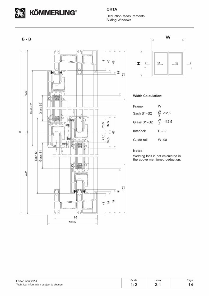
ORTA
Width Calculation:
Frame W
Sash S1=S2
Glass S1=S2
Interlock H -82
Guide rail W -98
Notes:
Welding loss is not calculated in the above mentioned deduction.
B - B
W2
-12,5
W2
-112,5
W/2
W/2
Sash S
2
Gla
ss S
2
Sash S
1
Gla
ss S
1
W
H
C C
S1 S3
S2
W
88
49
91 1
02
21,5
28,5
32,5
32,5
65
21,5
28,5
32,5
32,5
65
100,5
8
88
8
45
41
49
91
102
4541
Deduction MeasurementsSliding Windows
Edition April 2014
Technical information subject to change
Scale
1:2
Index
2.1
Page
15
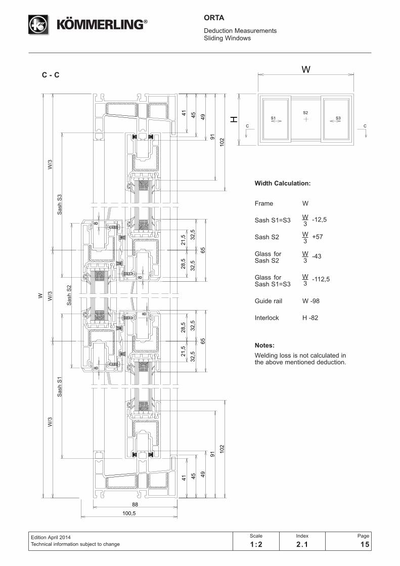
ORTA
Width Calculation:
Frame W
Sash S1=S3
Sash S2
Glass for Sash S2
Glass for Sash S1=S3
Guide rail W -98
Interlock H -82
Notes:
Welding loss is not calculated in the above mentioned deduction.
W3
-12,5
W3
-112,5
W3
-43
W3
+57
C - C
W/3
W/3
Sash S
3
W/3
Sash S
1
Sash S
2

88
W
21
,52
8,5
32
,53
2,5
65
21
,52
8,5
32
,53
2,5
65
4,5
4,5
54
,55
4,5
65
,56
5,5
100,5
49
91 1
02
8
88
8
45
41
49
91
10
2
4541
W
H D DS3 S4S1 S2
Deduction MeasurementsSliding Windows
Edition April 2014
Technical information subject to changenot to scale
Index
2.1
Page
16
ORTA
Width Calculation:
Frame W
Sashs S1=S4
Sashs S2=S3
Glass for Sashs S1=S4
Glass for Sashs S2=S3
Guide rail W -98
Interlock H -82
Butt profile H -82
Notes:
Welding loss is not calculated in the above mentioned deduction.
W4
-12,5
W4
-76
W4
-112,5
W4
+24
D - D
W/4
W/4
Sash S
4
W/4
Sash S
1
Sash S
3
W/4
Sash S
2
W
H B BS1 S2
88
W
34
12,5
100,5
28,5
35,5
39,5
39,5
79
49
105 116
8
8
41 45
49
105
116
41
45
Deduction MeasurementsSliding Doors
Edition April 2014
Technical information subject to change
Scale
1:2
Index
2.1
Page
17
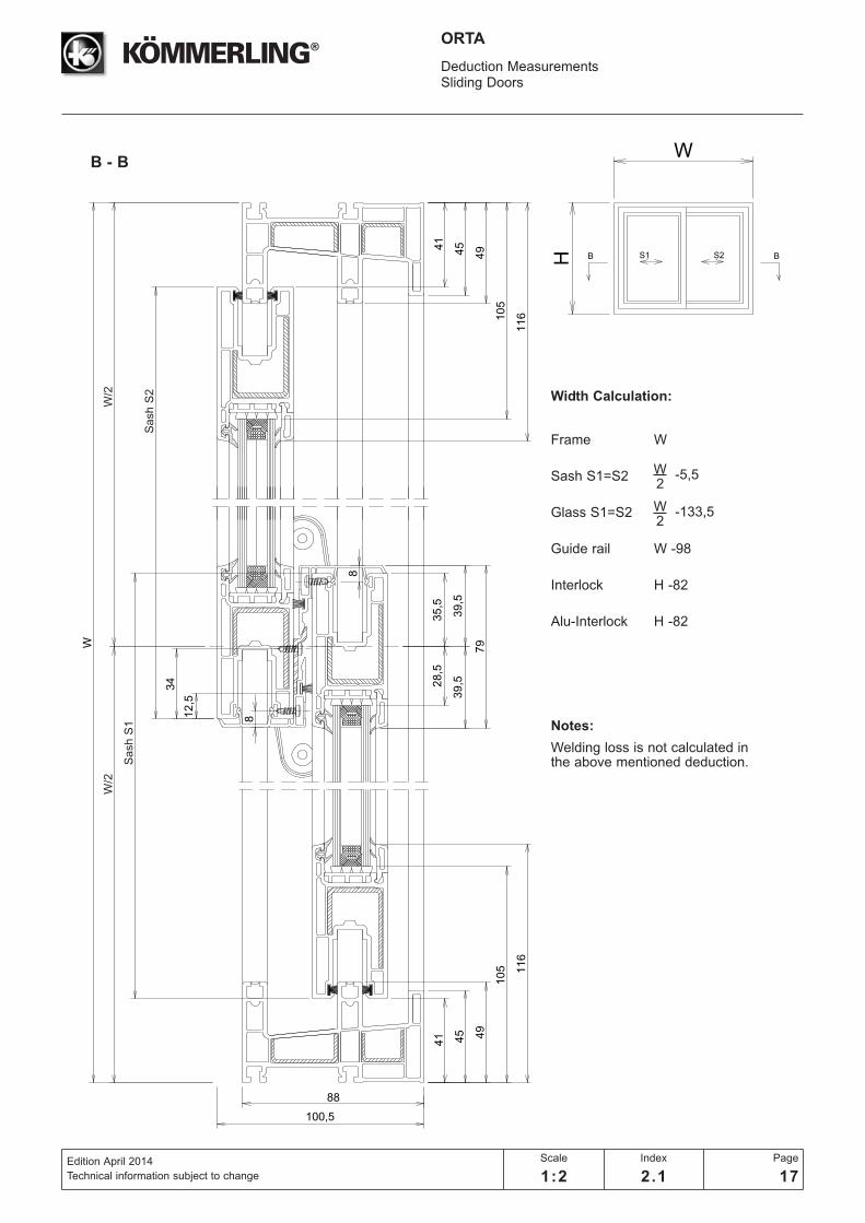
ORTA
B - B
Width Calculation:
Frame W
Sash S1=S2
Glass S1=S2
Guide rail W -98
Interlock H -82
Alu-Interlock H -82
Notes:
Welding loss is not calculated in the above mentioned deduction.
W2
-5,5
W2
-133,5
W/2
Sash S
2
W/2
Sash S
1

88
W
34
12
,5
100,5
49
10
5 11
6
28
,53
5,5
39
,53
9,5
79
28
,53
5,5
39
,53
9,5
79
8
88
8
34
12
,5
41 45
49
10
5
11
6
41
45
W
H
C C
S1 S3
S2
Deduction MeasurementsSliding Doors
Edition April 2014
Technical information subject to changenot to scale
Index
2.1
Page
18
ORTA
Width Calculation:
Frame W
Sash S1=S3
Sash S2
Glass for Sash S1=S3
Glass for Sash S2
Guide rail W -98
Interlock H -82
Alu-Interlock H -82
Notes:
Welding loss is not calculated in the above mentioned deduction.
W3
-5,5
W3
-57
W3
-133,5
W3
+71
C - C
W/3
Sash S
2
Sash S
3S
ash S
1
W/3
W/3
88
W
34
12
,5
34
12
,5
100,5
49
10
5 11
6
28
,53
5,5
39
,53
9,5
79
28
,53
5,5
39
,53
9,5
79
4,5
4,5
68
,56
8,5
79
,57
9,5
8
88
8
45
41
49
10
5
11
6
4541
W
H D DS3 S4S1 S2
Deduction MeasurementsSliding Doors
Edition April 2014
Technical information subject to changenot to scale
Index
2.1
Page
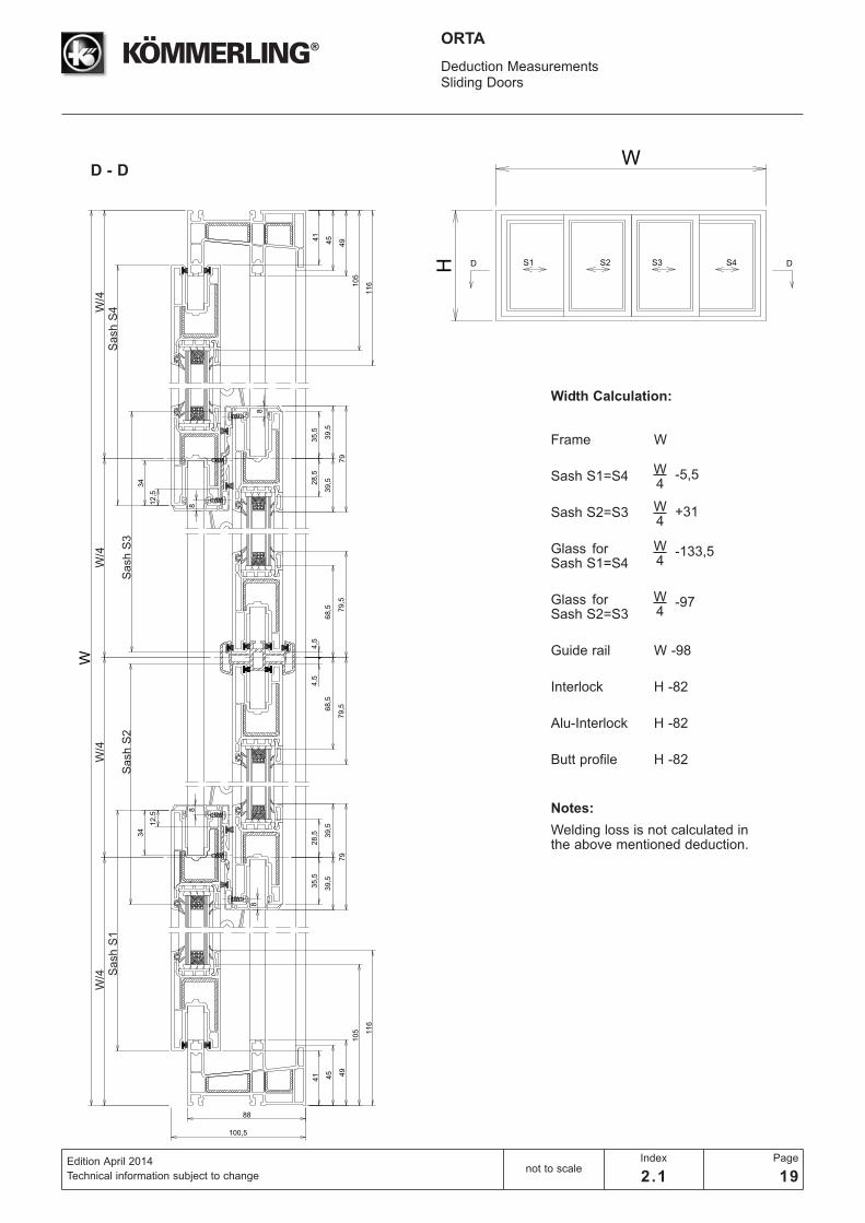
19
ORTA
Width Calculation:
Frame W
Sash S1=S4
Sash S2=S3
Glass for Sash S1=S4
Glass for Sash S2=S3
Guide rail W -98
Interlock H -82
Alu-Interlock H -82
Butt profile H -82
Notes:
Welding loss is not calculated in the above mentioned deduction.
W4
-5,5
W4
-97
W4
-133,5
W4
+31
D - D
Sash S
4S
ash S
3
W/4
W/4
Sash S
2
W/4
Sash S
1W
/4

58
H
A
A
W
H S3S1 S2
104
129
12,5
49
91 1
02
11,5
11,5
41
49
91
102
41
Deduction MeasurementsSliding Windows
Edition April 2014
Technical information subject to change
Scale
1:2
Index
2.1
Page
20
ORTA
Height Calculation:
Frame H
SashS1=S2=S3 H -82
Glass for H -182SashS1=S2=S3
Guide rail W -98
Interlock H -82
Notes:
Welding loss is not calculated in the above mentioned deduction.
A - A
Gla
ss S
1,S
2,S
3
Sash S
1,S
2,S
3

W
W
H B BS3S1 S2
104
21,5
28,5
32,5
32,5
65
21,5
28,5
32,5
32,5
65
129
8
49
911
02
11,5
8
88
8
41
49
91
102
41
11,5
12,5
Deduction MeasurementsSliding Windows
Edition April 2014
Technical information subject to change
Scale
1:2
Index
2.1
Page
21
ORTA
Width Calculation:
Frame W
Sash S1=S3
Sash S2
Glass for Sash S1=S3
Glass for Sash S2
Guide rail W -98
Interlock H -82
Notes:
Welding loss is not calculated in the above mentioned deduction.
W3
-12,5
W3
-43
W3
-112,5
W3
+57
B - B
W/3
W/3
Sash S
3
Sash S
2
Sa
sh S
1
W/3
104
W
138
49
91 1
02
4,5
4,5
54
,55
4,5
65
,56
5,5
21
,52
8,5
32
,53
2,5
65
11
,5
8
8
8
88
8
8
8
41
21
,52
8,5
32
,53
2,5
65
21
,52
8,5
32
,53
2,5
65
21
,52
8,5
32
,53
2,5
65
49
91
10
2
11
,5
41
12,5
W
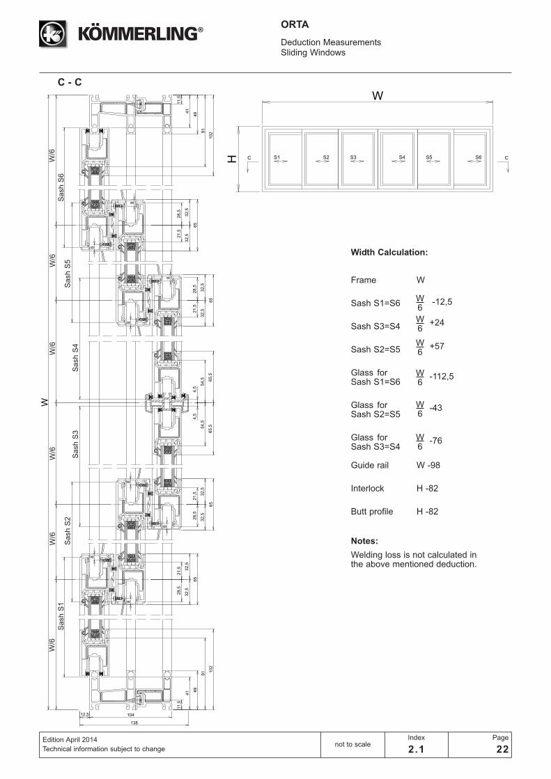
H C S3S1 S2 S4 S6S5
Deduction MeasurementsSliding Windows
Edition April 2014
Technical information subject to changenot to scale
Index
2.1
Page
22
ORTA
Width Calculation:
Frame W
Sash S1=S6
Sash S3=S4
Sash S2=S5
Glass for Sash S1=S6
Glass for Sash S2=S5
Glass for Sash S3=S4
Guide rail W -98
Interlock H -82
Butt profile H -82
Notes:
Welding loss is not calculated in the above mentioned deduction.
W6
-12,5
W6
-43
W6
+24
W6
-76
W6
-112,5
W6
+57
C - C
W/6
W/6
W/6
W/6
W/6
W/6
W
H C CS3S1 S2 S4 S6S5
Sash S
6S
ash S
5S
ash S
4S
ash S
3S
ash S
2S
ash S
1
W
104
129
49
10
511
6
28
,53
5,5
39
,53
9,5
79
28
,53
5,5
39
,53
9,5
79
8
88
8
34
12
,5
34
12
,5
41
49
10
5
11
6
41
11
,5
11
,5
W
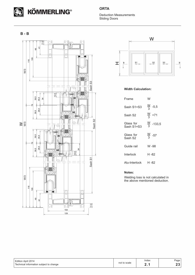
H B BS3S1 S2
Deduction MeasurementsSliding Doors
Edition April 2014
Technical information subject to changenot to scale
Index
2.1
Page
23
ORTA
Width Calculation:
Frame W
Sash S1=S3
Sash S2
Glass for Sash S1=S3
Glass for Sash S2
Guide rail W -98
Interlock H -82
Alu-Interlock H -82
Notes:
Welding loss is not calculated in the above mentioned deduction.
W3
-5,5
W3
-57
W3
-133,5
W3
+71
B - B
Sash S
2
Sash S
1S
ash S
3
W/3
W/3
W/3

104
W
4,5
4,5
68,5
68,5
79,5
79,5
34
12,5
28,5
35,5
39,5
39,5
79
138
12,5
49
105 116
34 28,5
35,5
39,5
39,5
79
34 28,5
35,5
39,5
39,5
79
28,5
35,5
39,5
39,5
79
34
12,5
12,5
12,5
8
8
8
8
8
88
8
41
49
105
116
41
11,5
11,5
W
H C S3S1 S2 S4 SS5
Deduction MeasurementsSliding Doors
Edition April 2014
Technical information subject to changenot to scale
Index
2.1
Page
24
ORTA
Width Calculation:
Frame W
Sash S1=S6
Sash S2=S5
Sash S3=S4
Glass for Sash S1=S6
Glass for Sash S2=S5
Glass for Sash S3=S4
Guide rail W -98
Interlock H -82
Alu-Interlock H -82
Butt-profile H -82
Notes:
Welding loss is not calculated in the above mentioned deduction.
W6
-5,5
W6
-133,5
W6
-57
W6
-97
W6
+31
W6
+71
C - C
W/6
W/6
W/6
W/6
W/6
W/6
Sash S
6S
ash S
4S
ash S
3S
ash S
1S
ash
S2
Sash
S5
W
H C CS3S1 S2 S4 S6S5
H
W
H
Hs
Hs
A
A
Hc
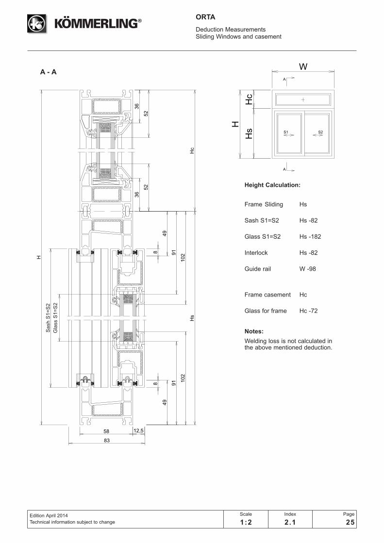
S1 S2
58
8
49
91 1
02
12,5
83
8
49
91
102
Hc
36
52
36
52
Deduction MeasurementsSliding Windows and casement
Edition April 2014
Technical information subject to change
Scale
1:2
Index
2.1
Page
25
ORTA
Height Calculation:
Frame Sliding Hs
Sash S1=S2 Hs -82
Glass S1=S2 Hs -182
Interlock Hs -82
Guide rail W -98
Frame casement Hc
Glass for frame Hc -72
Notes:
Welding loss is not calculated in the above mentioned deduction.
A - A
Gla
ss S
1=
S2
Sash S
1=
S2
58
52
W
W
H
Hs
B B
Hc
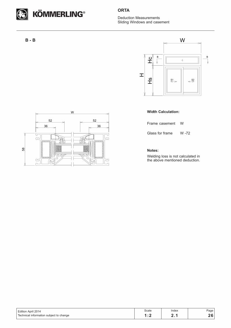
S1 S2
36
52
36
Deduction MeasurementsSliding Windows and casement
Edition April 2014
Technical information subject to change
Scale
1:2
Index
2.1
Page
26
ORTA
Width Calculation:
Frame casement W
Glass for frame W -72
Notes:
Welding loss is not calculated in the above mentioned deduction.
B - B
15,3
113,3
IG
IW
29,3
4949
63,4
58
2,7
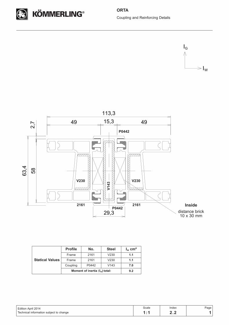
ORTA
Coupling and Reinforcing Details
Edition April 2014
Technical information subject to change
Scale
1:1
Index
2.2
Page
1
Statical Values
Profile No. Steel Iw cm4
Frame 2161 V230 1.1
Frame 2161 V230 1.1
Coupling P0442 V143 7.0
Moment of inertia (Iw) total: 9.2
2161 2161P0442
P0442
V1
43 V230V230
Inside
distance brick10 x 30 mm
IG
IW
29,3
113,3
15,3
77,2
58
16,5
49 49
2,7
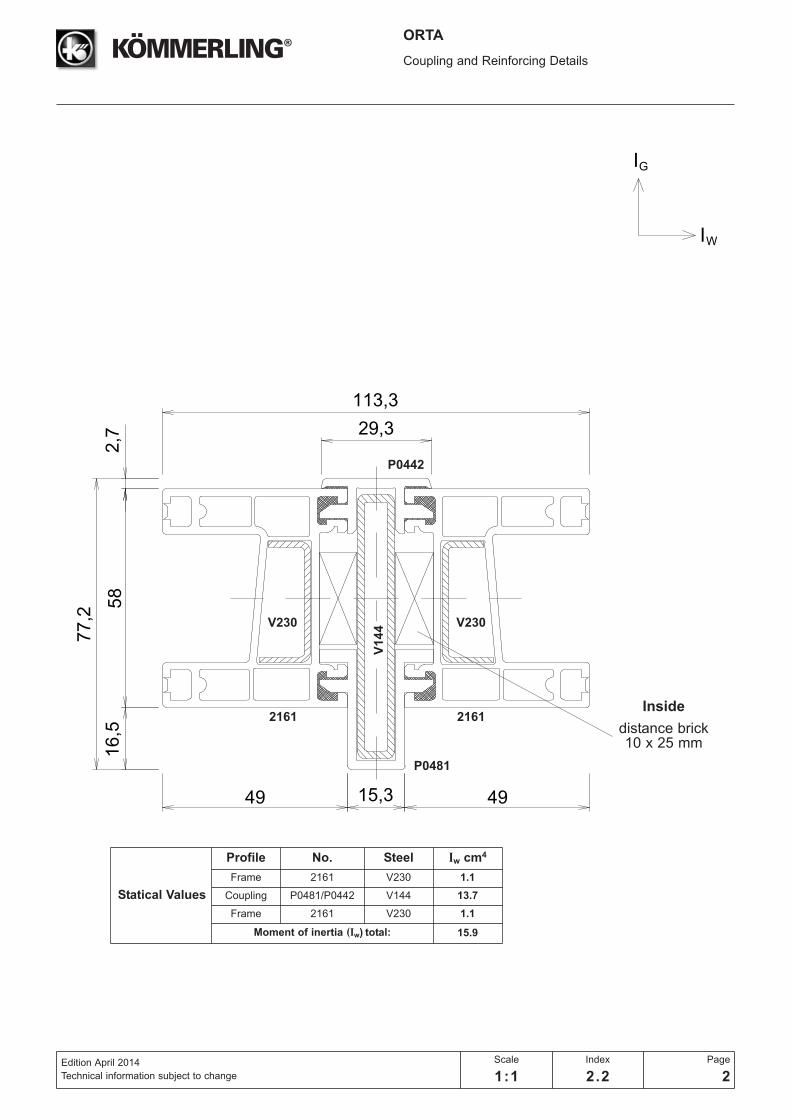
ORTA
Coupling and Reinforcing Details
Edition April 2014
Technical information subject to change
Scale
1:1
Index
2.2
Page
2
Statical Values
Profile No. Steel Iw cm4
Frame 2161 V230 1.1
Coupling P0481/P0442 V144 13.7
Frame 2161 V230 1.1
Moment of inertia (Iw) total: 15.9
2161 2161
P0442
P0481
Inside
distance brick10 x 25 mm
V1
44 V230V230

IG
IW
15,3
113,3
91
58
16,5
16,5
49 49
ORTA
Coupling and Reinforcing Details
Edition April 2014
Technical information subject to change
Scale
1:1
Index
2.2
Page
3
Statical Values
Profile No. Steel Iw cm4
Frame 2161 V230 1.1
Coupling P0481 G9704 18.8
Frame 2161 V230 1.1
Moment of inertia (Iw) total: 21.0
2161 2161
P0481
Inside
distance brick10 x 25 mm
G9
70
4
V230V230

2
100
IG
IW
4949
63,4
58
2,7
16
ORTA
Coupling and Reinforcing Details
Edition April 2014
Technical information subject to change
Scale
1:1
Index
2.2
Page
4
2161 2161
P1677
P1677distance brick10 x 30 mm7 x 30 mm
V230V230
Statical Values
Profile No. Steel Iw cm4
Frame 2161 V230 1.1
Frame 2161 V230 1.1
Moment of inertia (Iw) total: 2.2

98
IG
IW
4949
58
ORTA
Coupling and Reinforcing Details
Edition April 2014
Technical information subject to change
Scale
1:1
Index
2.2
Page
5
2161 2161
P1248
P1248distance brick
7 x 30 mm
V230V230
Statical Values
Profile No. Steel Iw cm4
Frame 2161 V230 1.1
Frame 2161 V230 1.1
Moment of inertia (Iw) total: 2.2
67
49
67
IG
IW
60
109
60
109
58
49
ORTA
Coupling and Reinforcing Details
Edition April 2014
Technical information subject to change
Scale
1:1
Index
2.2
Page
6
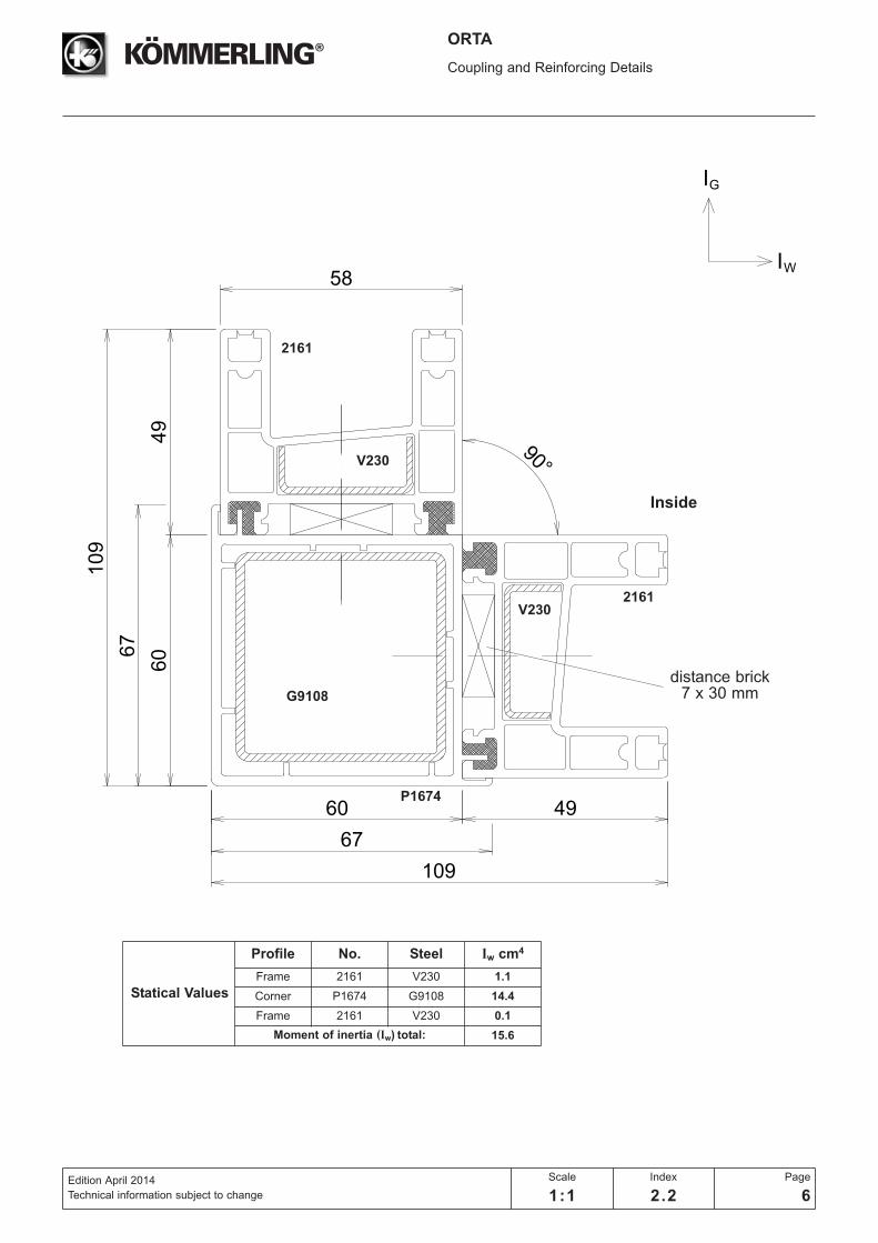
P1674
2161
2161
Statical Values
Profile No. Steel Iw cm4
Frame 2161 V230 1.1
Corner P1674 G9108 14.4
Frame 2161 V230 0.1
Moment of inertia (Iw) total: 15.6
Inside
distance brick 7 x 30 mm
V230
V230
G9108
80 49
58
IG
IW
107
49
129
58
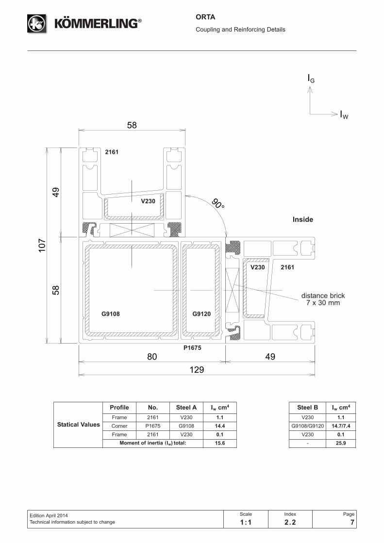
ORTA
Coupling and Reinforcing Details
Edition April 2014
Technical information subject to change
Scale
1:1
Index
2.2
Page
7
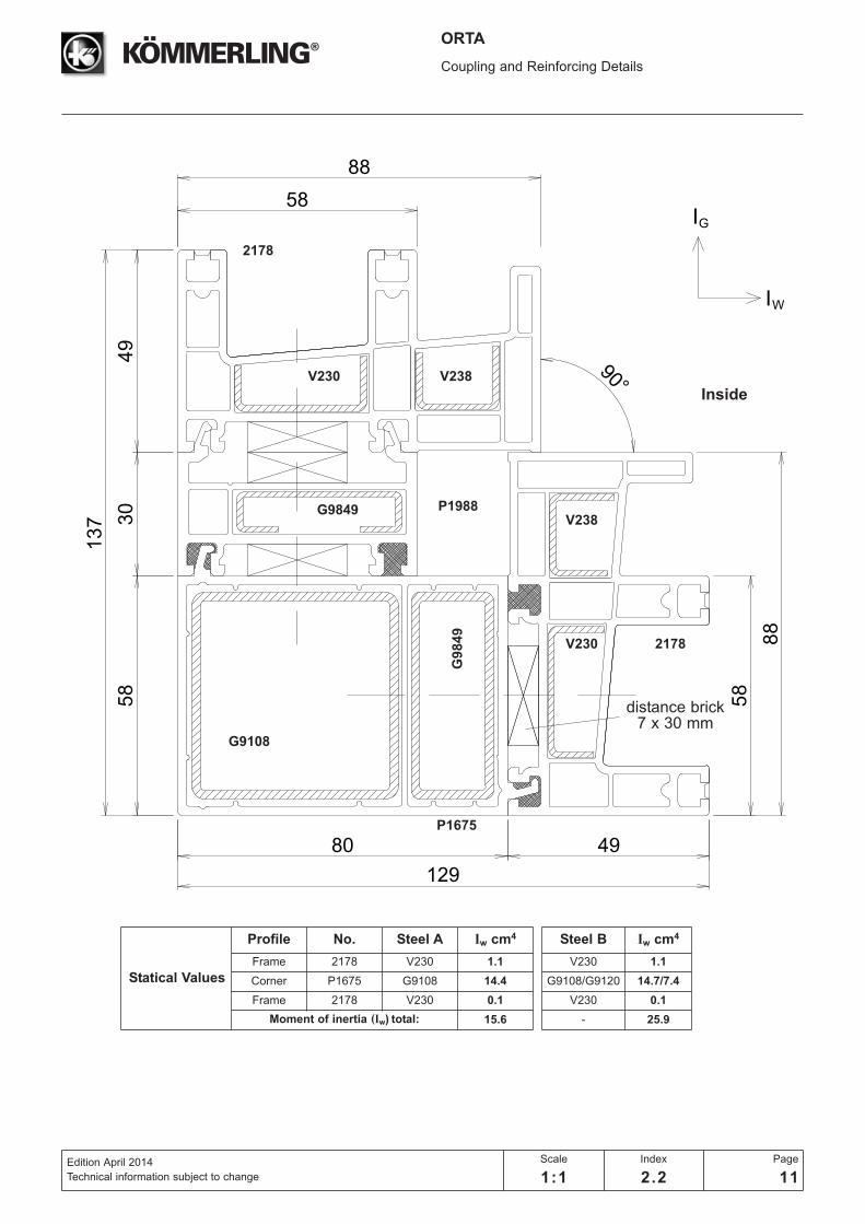
Statical Values
Profile No. Steel A Iw cm4
Frame 2161 V230 1.1
Corner P1675 G9108 14.4
Frame 2161 V230 0.1
Moment of inertia (Iw) total: 15.6
Steel B Iw cm4
V230 1.1
G9108/G9120 14.7/7.4
V230 0.1
- 25.9
P1675
2161
2161
Inside
distance brick 7 x 30 mm
V230
V230
G9108 G9120

35,3 49
IG
IW
58
49
35,3
X =
67,2
X = 67,2
"A"R40
ORTA
Coupling and Reinforcing Details
Edition April 2014
Technical information subject to change
Scale
1:1
Index
2.2
Page
8
P1996
P1973
P1973
2161
2161
M9040
M90400
Statical Values
Profile No. Steel Iw cm4
Frame 2161 V230 1.1
Corner P1996/P1973 V123 11.7
Frame 2161 V230 0.4
Moment of inertia (Iw) total: 13.2
Inside
distance brick 7 x 30 mm
V230
V230
“A” 100° 105° 110° 115° 120° 125° 130° 135° 140° 145° 150° 155° 160° 165° 170°
“X” in mm
84.7 81.7 78.9 76.4 73.9 71.6 69.4 67.2 65.2 63.2 61.2 59.3 57.5 55.6 53.8

58
30
88
49 49
98
IG
IW
ORTA
Coupling and Reinforcing Details
Edition April 2014
Technical information subject to change
Scale
1:1
Index
2.2
Page
9
21782178
P1248distance brick
7 x 30 mm
V238V238
V230V230
Statical Values
Profile No. Steel Iw cm4
Frame 2178 V230 1.1
Frame 2178 V230 1.1
Moment of inertia (Iw) total: 2.2

IG
IW
30
67
60
139
60
109
58
88
49
49
ORTA
Coupling and Reinforcing Details
Edition April 2014
Technical information subject to change
Scale
1:1
Index
2.2
Page
10
Statical Values
Profile No. Steel A Iw cm4
Frame 2178 V230 1.1
Corner P1674 G9108 14.4
Frame 2178 V230 0.1
Moment of inertia (Iw) total: 15.6
Steel B Iw cm4
V230 1.1
G9108/G9120 14.7/7.4
V230 0.1
- 25.9
P1674
2178
2178
Inside
distance brick 7 x 30 mm
V230 V238
V238
V230
G9108
G9849G
98
49
P1988
80 49
58
IG
IW
137
49
129
58
88
30
58
88
ORTA
Coupling and Reinforcing Details
Edition April 2014
Technical information subject to change
Scale
1:1
Index
2.2
Page
11
Statical Values
Profile No. Steel A Iw cm4
Frame 2178 V230 1.1
Corner P1675 G9108 14.4
Frame 2178 V230 0.1
Moment of inertia (Iw) total: 15.6
Steel B Iw cm4
V230 1.1
G9108/G9120 14.7/7.4
V230 0.1
- 25.9
P1675
2178
2178
Inside
distance brick 7 x 30 mm
V230 V238
V238
V230
G9108
G9849
G9
84
9
P1988
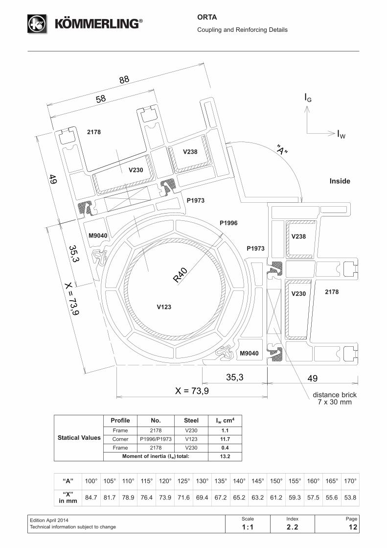
IG
IW
35,3 49
"A"
58
88
49
35,3
X =
73,9
X = 73,9
R40
ORTA
Coupling and Reinforcing Details
Edition April 2014
Technical information subject to change
Scale
1:1
Index
2.2
Page
12
P1996
P1973
P1973
V123
2178
2178
V230
V238
V230
V238
M9040
M9040
Statical Values
Profile No. Steel Iw cm4
Frame 2178 V230 1.1
Corner P1996/P1973 V123 11.7
Frame 2178 V230 0.4
Moment of inertia (Iw) total: 13.2
Inside
distance brick 7 x 30 mm
“A” 100° 105° 110° 115° 120° 125° 130° 135° 140° 145° 150° 155° 160° 165° 170°
“X” in mm
84.7 81.7 78.9 76.4 73.9 71.6 69.4 67.2 65.2 63.2 61.2 59.3 57.5 55.6 53.8
IG
IW
101
5249
58
ORTA
Coupling and Reinforcing Details
Edition April 2014
Technical information subject to change
Scale
1:1
Index
2.2
Page
13
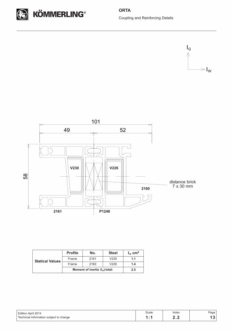
Statical Values
Profile No. Steel Iw cm4
Frame 2161 V230 1.1
Frame 2160 V226 1.4
Moment of inertia (Iw) total: 2.5
2161
2160
P1248
V226V230
distance brick7 x 30 mm
IG
IW
88
101
5249
45 33
58
ORTA
Coupling and Reinforcing Details
Edition April 2014
Technical information subject to change
Scale
1:1
Index
2.2
Page
14
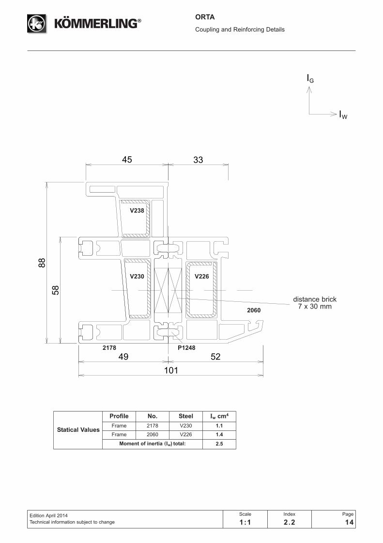
2178
2060
P1248
V226V230
V238
distance brick7 x 30 mm
Statical Values
Profile No. Steel Iw cm4
Frame 2178 V230 1.1
Frame 2060 V226 1.4
Moment of inertia (Iw) total: 2.5
IG
IW
104
58
49 33
101
5249
ORTA
Coupling and Reinforcing Details
Edition April 2014
Technical information subject to change
Scale
1:1
Index
2.2
Page
15
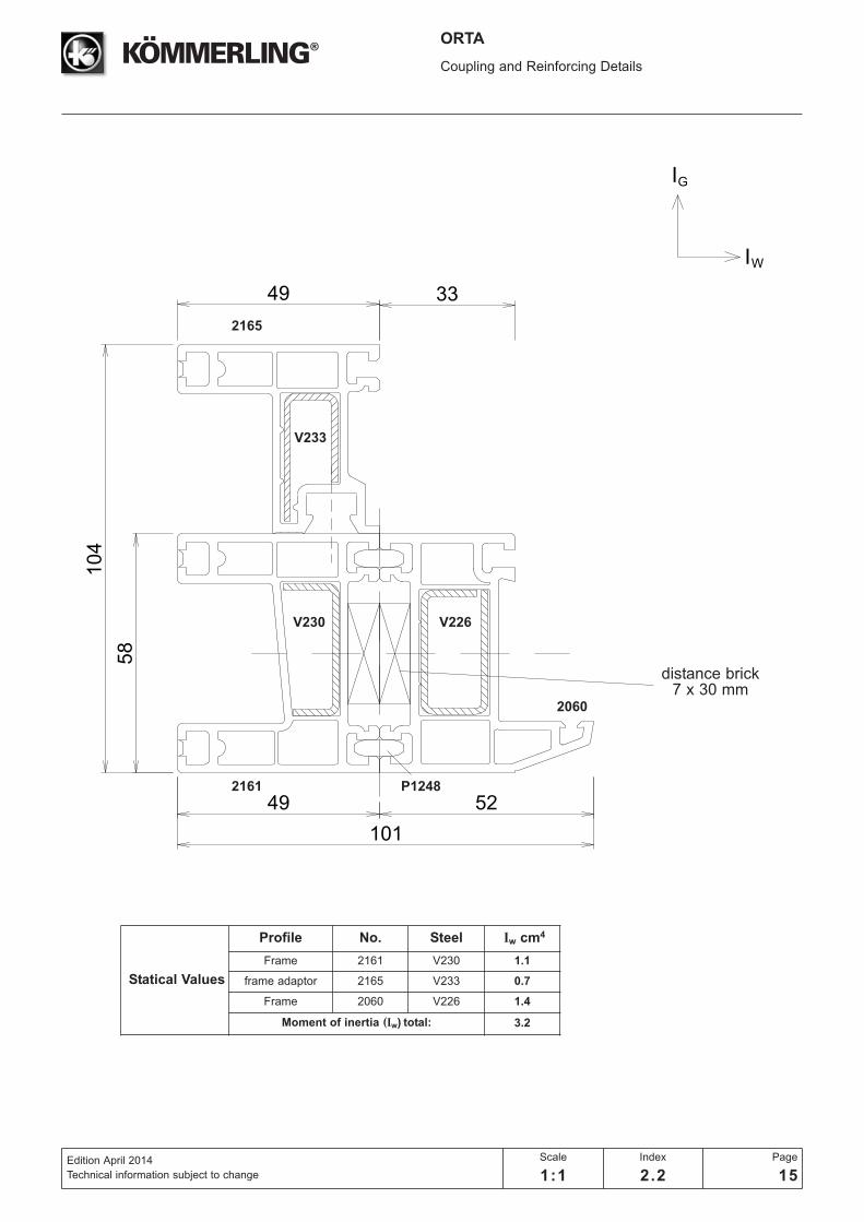
2161
2165
2060
P1248
V226V230
V233
distance brick7 x 30 mm
Statical Values
Profile No. Steel Iw cm4
Frame 2161 V230 1.1
frame adaptor 2165 V233 0.7
Frame 2060 V226 1.4
Moment of inertia (Iw) total: 3.2
IG
IW
80 52
58
107
49
132
58
88 25
45
ORTA
Coupling and Reinforcing Details
Edition April 2014
Technical information subject to change
Scale
1:1
Index
2.2
Page
16
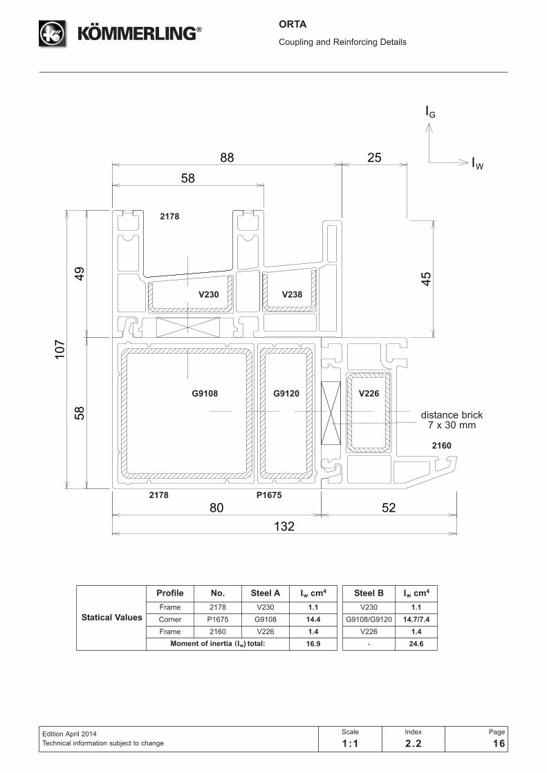
2178
2160
2178
P1675
G9120G9108
V230 V238
V226
distance brick7 x 30 mm
Statical Values
Profile No. Steel A Iw cm4
Frame 2178 V230 1.1
Corner P1675 G9108 14.4
Frame 2160 V226 1.4
Moment of inertia (Iw) total: 16.9
Steel B Iw cm4
V230 1.1
G9108/G9120 14.7/7.4
V226 1.4
- 24.6
50
max. 600A
A
5
12
23
5
12,5
5
12
23
5
12
23
5
12
23
5
12,5
12
5
28,5
35,3
22 12,4
5
50
max 600
50
1/2 W 1/2 W
50
6
5
6
5
ORTA
General GuidelinesDrainage and Pressure Equalization
Edition April 2014
Technical information subject to change
Scale
1:2
Index
3.1
Page
1
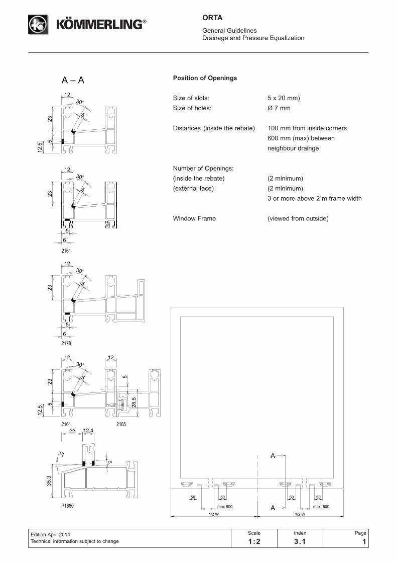
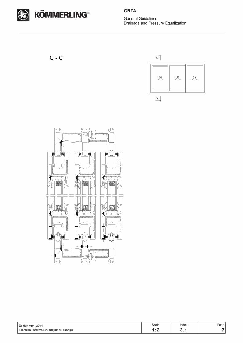
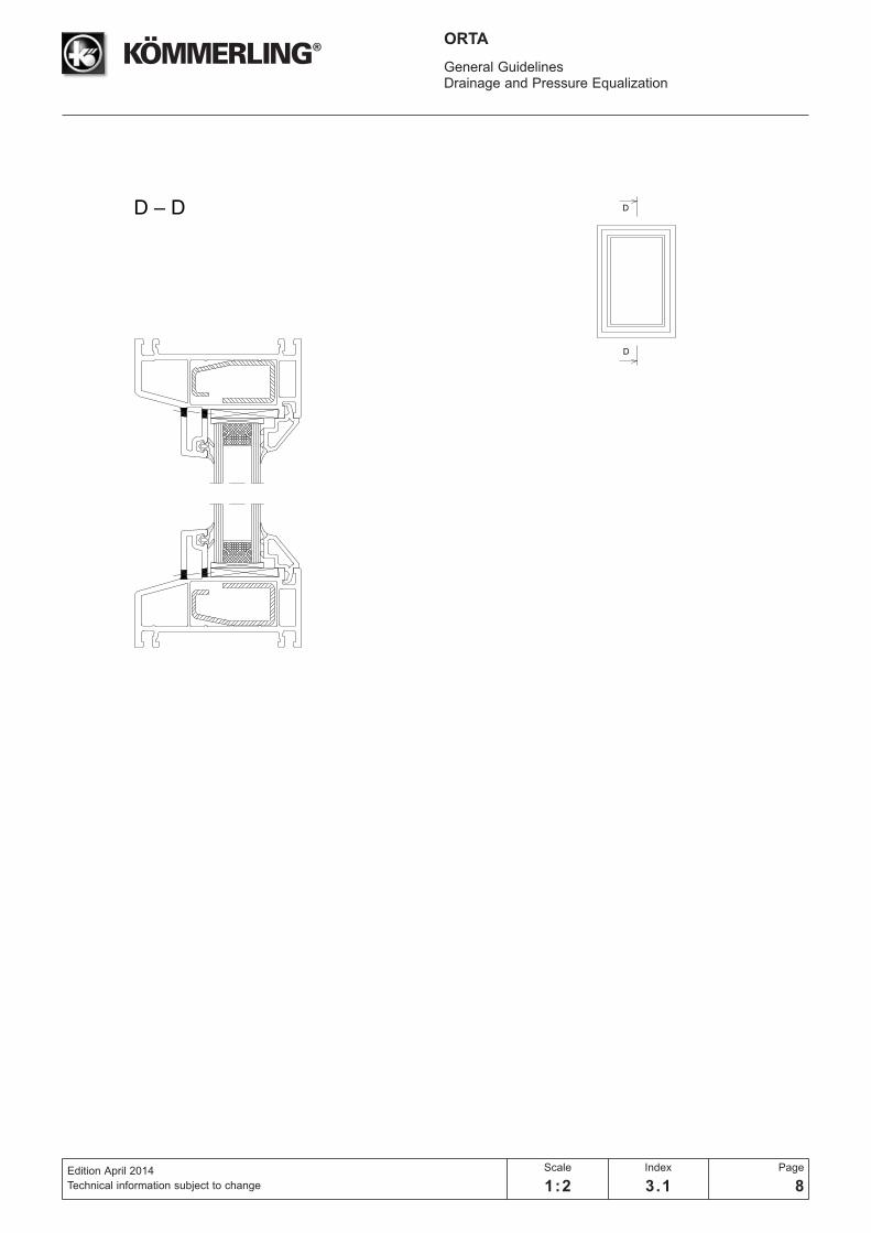
Position of Openings
Size of slots: 5 x 20 mm)
Size of holes: Ø 7 mm
Distances (inside the rebate) 100 mm from inside corners
600 mm (max) between
neighbour drainge
Number of Openings:
(inside the rebate) (2 minimum)
(external face) (2 minimum)
3 or more above 2 m frame width
Window Frame (viewed from outside)

100
20
50
20
max. 600
20
50
20
100
W / 2
100
20
50
20
max. 600
20
50
20
100
W / 2
BB
CC
B-B
C-C
ORTA
General GuidelinesDrainage and Pressure Equalization
Edition April 2014
Technical information subject to change
Scale
1:2
Index
3.1
Page
2
Distances for frame

5
4,6
16
6
5
22,8
4,3
5
6
5
16
30,7
34
61
75
37
37
Window sash
2170
Door sash
2172
ORTA
General GuidelinesDrainage and Pressure Equalization
Edition April 2014
Technical information subject to change
Scale
1:1
Index
3.1
Page
3

20
20
20
20
100
100
100
100
max. 600
max. 600
W / 2
W / 2
AA
AA
A-A
A-A
2,5
2,5
ORTA
General GuidelinesDrainage and Pressure Equalization
Edition April 2014
Technical information subject to change
Scale
1:2
Index
3.1
Page
4
Distances for sash
A
A
ORTA
General GuidelinesDrainage and Pressure Equalization
Edition April 2014
Technical information subject to change
Scale
1:2
Index
3.1
Page
5

B
B
ORTA
General GuidelinesDrainage and Pressure Equalization
Edition April 2014
Technical information subject to change
Scale
1:2
Index
3.1
Page
6
C
C
S3S1 S2
C - C
ORTA
General GuidelinesDrainage and Pressure Equalization
Edition April 2014
Technical information subject to change
Scale
1:2
Index
3.1
Page
7
D
D
ORTA
General GuidelinesDrainage and Pressure Equalization
Edition April 2014
Technical information subject to change
Scale
1:2
Index
3.1
Page
8
ORTA
General GuidelinesDrainage and Pressure Equalization
Edition April 2014
Technical information subject to change
Scale
1:2
Index
3.1
Page
9
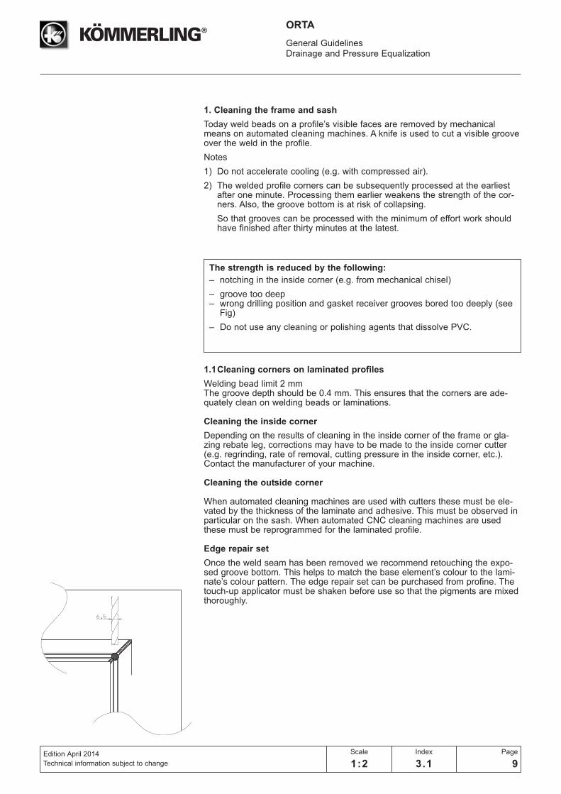
1. Cleaning the frame and sash
Today weld beads on a profile’s visible faces are removed by mechanicalmeans on automated cleaning machines. A knife is used to cut a visible grooveover the weld in the profile.
Notes
1) Do not accelerate cooling (e.g. with compressed air).
2) The welded profile corners can be subsequently processed at the earliestafter one minute. Processing them earlier weakens the strength of the cor-ners. Also, the groove bottom is at risk of collapsing.
So that grooves can be processed with the minimum of effort work shouldhave finished after thirty minutes at the latest.
The strength is reduced by the following:
– notching in the inside corner (e.g. from mechanical chisel)
– groove too deep– wrong drilling position and gasket receiver grooves bored too deeply (see
Fig)
– Do not use any cleaning or polishing agents that dissolve PVC.
1.1Cleaning corners on laminated profiles
Welding bead limit 2 mmThe groove depth should be 0.4 mm. This ensures that the corners are ade-quately clean on welding beads or laminations.
Cleaning the inside corner
Depending on the results of cleaning in the inside corner of the frame or gla-zing rebate leg, corrections may have to be made to the inside corner cutter(e.g. regrinding, rate of removal, cutting pressure in the inside corner, etc.).Contact the manufacturer of your machine.
Cleaning the outside corner
When automated cleaning machines are used with cutters these must be ele-vated by the thickness of the laminate and adhesive. This must be observed inparticular on the sash. When automated CNC cleaning machines are usedthese must be reprogrammed for the laminated profile.
Edge repair set
Once the weld seam has been removed we recommend retouching the expo-sed groove bottom. This helps to match the base element’s colour to the lami-nate’s colour pattern. The edge repair set can be purchased from profine. Thetouch-up applicator must be shaken before use so that the pigments are mixedthoroughly.
ORTA
General GuidelinesGlazing Table and Accessories
Edition April 2014
Technical information subject to change
Scale
1:1
Index
3.2
Page
1
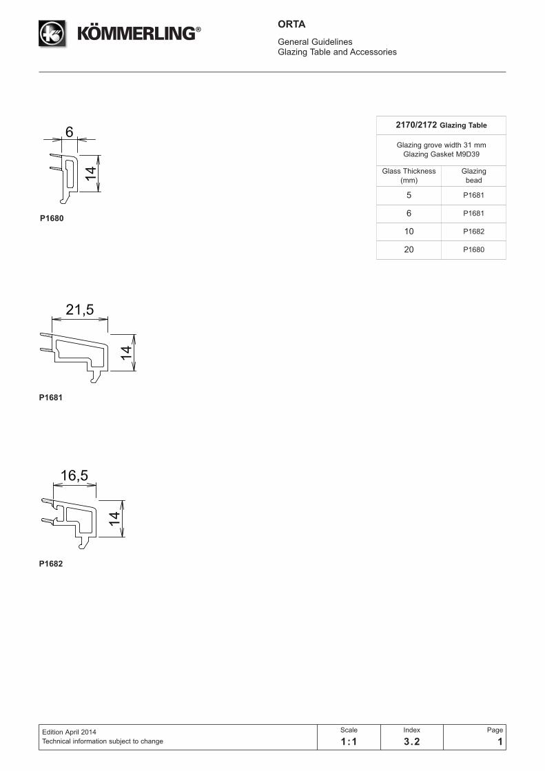
2170/2172 Glazing Table
Glazing grove width 31 mm
Glazing Gasket M9D39
Glass Thickness
(mm)
Glazing
bead
5 P1681
6 P1681
10 P1682
20 P1680
P1680
P1681
P1682
1,0
2,5
3,03,5
50
60
70
80
90
100
110
120
130
140
150
160
170
180
190
200
210
220
230
240
250
50 60 70 80 90 100 110 120 130 140 150 160 170 180 190 200
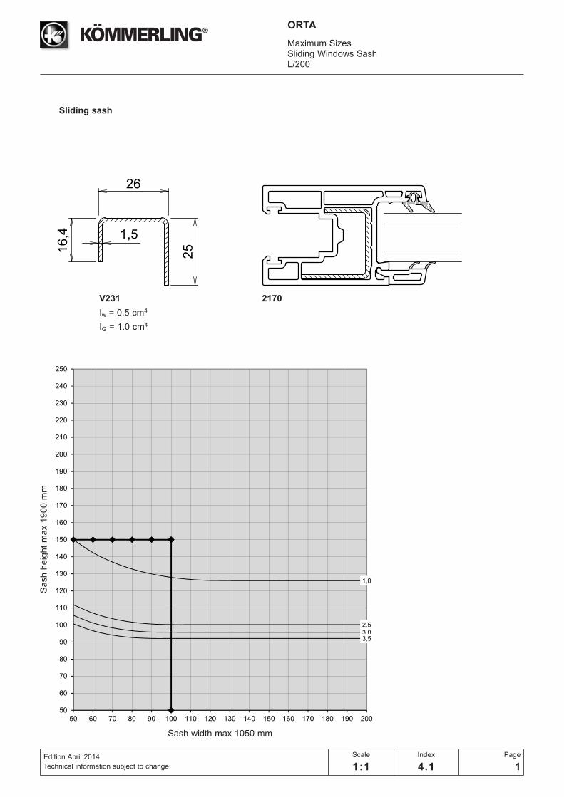
16,4
2625
1,5
ORTA
Maximum SizesSliding Windows SashL/200
Edition April 2014
Technical information subject to change
Scale
1:1
Index
4.1
Page
1
Sliding sash
Sash h
eig
ht
ma
x 1
90
0 m
m
Sash width max 1050 mm
V231
Iw = 0.5 cm4
IG = 1.0 cm4
2170
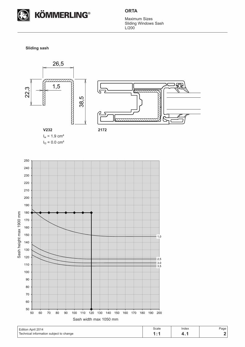
22,3
26,5
38,5
1,5
ORTA
Maximum SizesSliding Windows SashL/200
Edition April 2014
Technical information subject to change
Scale
1:1
Index
4.1
Page
2
Sliding sash
V232
Iw = 1.9 cm4
IG = 0.0 cm4
2172
1,0
2,5
3,03,5
50
60
70
80
90
100
110
120
130
140
150
160
170
180
190
200
210
220
230
240
250
50 60 70 80 90 100 110 120 130 140 150 160 170 180 190 200
Sash h
eig
ht
ma
x 1
90
0 m
m
Sash width max 1050 mm