Embed Size (px)
Citation preview

InformationPower Parts
www.ktm.com
772399740445153997404407. 2010 3.211.567
*3211567*
Danke, dass Sie sich für KTM Power Parts entschlossen haben.Alle unsere Produkte wurden nach den höchsten Standards entwickelt und gefertigt, unter Verwendung der besten verfügbarenMaterialien.KTM Power Parts sind rennerprobt und gewährleisten ultimative Performance.
KTM KANN NICHT VERANTWORTLICH GEMACHT WERDEN FÜR FALSCHE MONTAGE ODER VERWENDUNG DIESES PRODUKTS. Bittebefolgen Sie die Montageanleitung. Fachmännische Beratung und korrekte Installation der KTM PowerParts durch einen autorisiertenKTM Händler sind unerlässlich, um das Optimum an Sicherheit und Funktionalität zu gewährleisten.Danke.
Thank you for choosing KTM Power Parts! All of our products are designed and built to the highest standards using the finest materials available.KTM Power Parts are race proven to offer the ultimate in performance.
KTM WILL NOT BE HELD LIABLE FOR IMPROPER INSTALLATION OR USE OF THIS PRODUCT. Please follow all instructions provided.Professional advice and proper installation of the KTM PowerParts by an authorized KTM dealer are essential to provide maximumsafety and functions.Thank you.
Grazie per aver deciso di acquistare un prodotto KTM Power Parts.Tutti i nostri prodotti sono stati sviluppati e realizzati secondo i massimi standard e con l'impiego dei migliori materiali disponibili.Le KTM Power Parts sono collaudate nelle competizioni ed assicurano altissime prestazioni.
KTM NON PUÒ ESSERE RESA RESPONSABILE PER UN MONTAGGIO O USO IMPROPRIO DI QUESTO PRODOTTO. Per favore osservate leistruzioni nel manuale d'uso. Al fine di garantire la massima sicurezza e il corretto funzionamento, è indispensabile farsi consigliareda persone esperte e competenti e far eseguire l'installazione delle KTM PowerPart presso i concessionari KTM autorizzati.Grazie.
Nous vous remercions d'avoir choisi KTM Power Parts.Tous nos produits ont été développés et réalisés selon les plus hauts standards et en utilisant les meilleurs matériaux disponibles.Les Power Parts de KTM ont fait leurs preuves en compétition et garantissent les meilleures performances.
LA RESPONSABILITÉ DE KTM NE SAURAIT ÊTRE ENGAGÉE EN CAS D'ERREUR DANS LE MONTAGE OU L'UTILISATION DE CE PRODUIT.Il convient de respecter les instructions de montage. Le conseil spécialisé et l'installation dans les règles de l'art des PowerParts KTM par un concessionnaire KTM agréé sontindispensables pour assurer un maximum de sécurité et de fonctionnalité.Merci.
Gracias por haberse decidido por el Power Parts KTM.Todos nuestros productos han sido desarrollados y producidos según los estándares más altos utilizando los mejores materialesdisponibles.Las KTM Power Parts están probadas en competencia y garantizan un óptimo rendimiento.
NO SE PUEDE HACER RESPONSABLE A LA KTM POR UN MONTAJE O UN USO INCORRECTO DE ESTE PRODUCTO.Le rogamos seguir las instrucciones para el montaje.A fin de garantizar la máxima seguridad y un funcionamiento correcto es imprescindible acudir a un concesionario autorizado de KTMpara obtener el mejor asesoramiento técnico e instalar correctamente las KTM PowerParts.Gracias.
DEU
TSCH
2
ENGL
ISH
2
ESPA
NOL
2
ITAL
IAN
O
2
FRAN
CAIS
2
DEU
TSCH
3
Vorarbeiten
- Sitzbank entfernen (siehe Bedienungsanleitung).- Tank entfernen (siehe Bedienungsanleitung).
Montage
Montage Schalter am Lenker 2-Takt und 4-Takt
- Schelle der Bremsarmatur demontieren und Zündkurvenschalter (2a) mon-tieren.
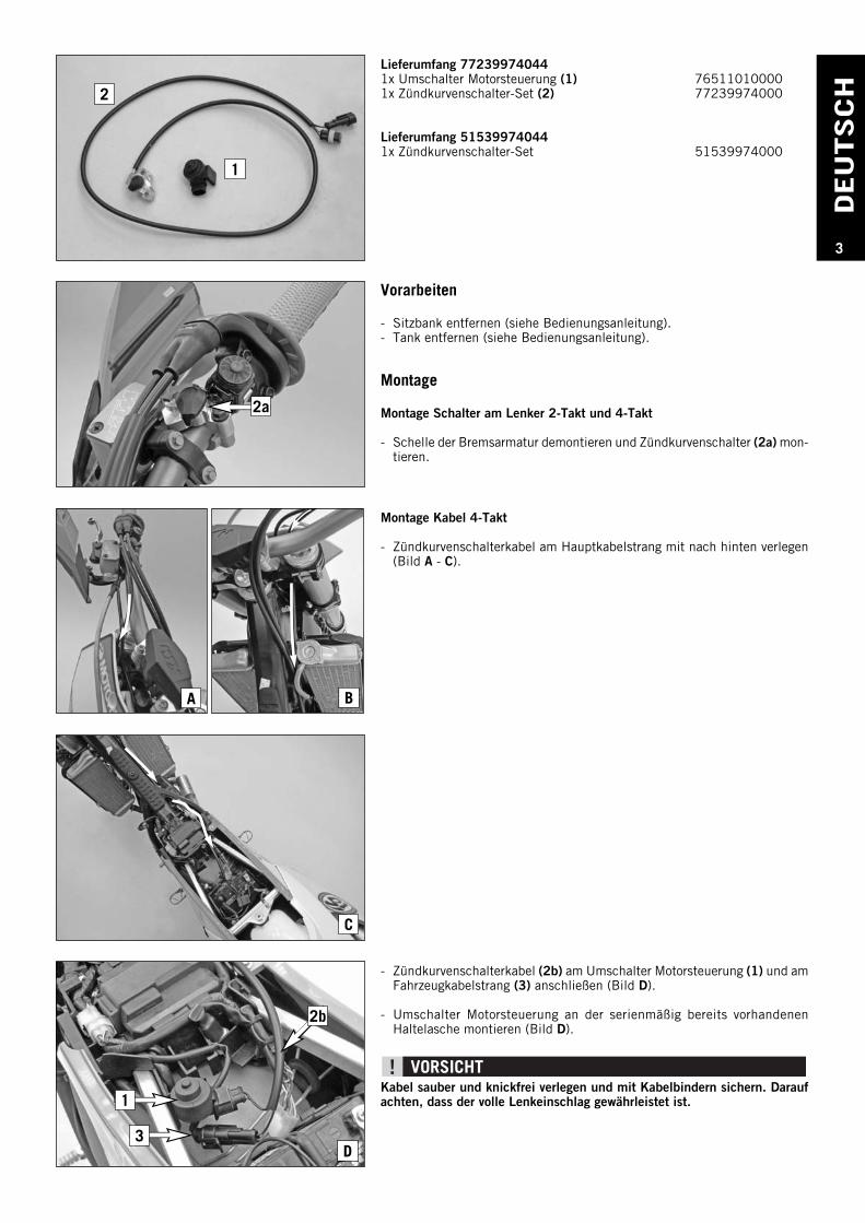
Lieferumfang 772399740441x Umschalter Motorsteuerung (1) 765110100001x Zündkurvenschalter-Set (2) 77239974000
Lieferumfang 515399740441x Zündkurvenschalter-Set 51539974000
Montage Kabel 4-Takt
- Zündkurvenschalterkabel am Hauptkabelstrang mit nach hinten verlegen(Bild A - C).
- Zündkurvenschalterkabel (2b) am Umschalter Motorsteuerung (1) und amFahrzeugkabelstrang (3) anschließen (Bild D).
- Umschalter Motorsteuerung an der serienmäßig bereits vorhandenenHaltelasche montieren (Bild D).
Kabel sauber und knickfrei verlegen und mit Kabelbindern sichern. Daraufachten, dass der volle Lenkeinschlag gewährleistet ist.
1
2
A B
C
D
1
3
2b
2a
DEU
TSCH
4
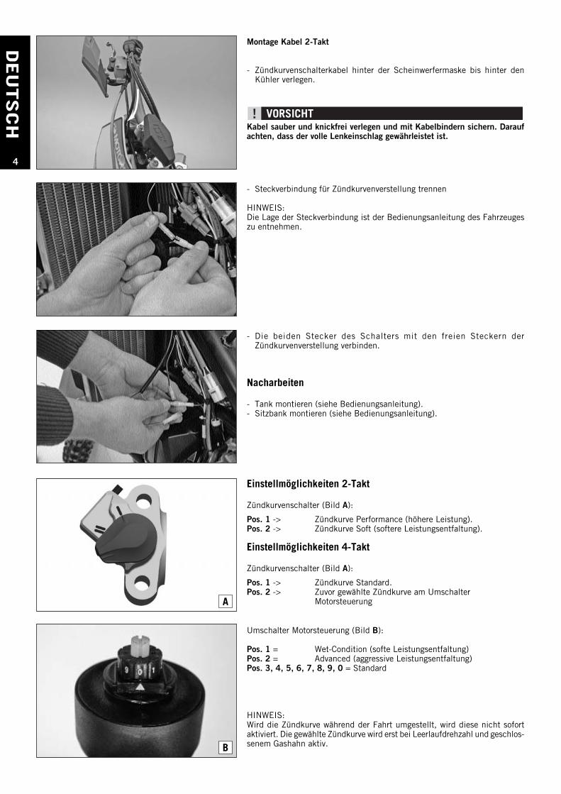
Montage Kabel 2-Takt
- Zündkurvenschalterkabel hinter der Scheinwerfermaske bis hinter denKühler verlegen.
Kabel sauber und knickfrei verlegen und mit Kabelbindern sichern. Daraufachten, dass der volle Lenkeinschlag gewährleistet ist.
- Steckverbindung für Zündkurvenverstellung trennen
HINWEIS:Die Lage der Steckverbindung ist der Bedienungsanleitung des Fahrzeugeszu entnehmen.
Einstellmöglichkeiten 2-Takt
Zündkurvenschalter (Bild A):
Pos. 1 -> Zündkurve Performance (höhere Leistung).Pos. 2 -> Zündkurve Soft (softere Leistungsentfaltung).
Einstellmöglichkeiten 4-Takt
Zündkurvenschalter (Bild A):
Pos. 1 -> Zündkurve Standard.Pos. 2 -> Zuvor gewählte Zündkurve am Umschalter
Motorsteuerung
Umschalter Motorsteuerung (Bild B):
Pos. 1 = Wet-Condition (softe Leistungsentfaltung)Pos. 2 = Advanced (aggressive Leistungsentfaltung)Pos. 3, 4, 5, 6, 7, 8, 9, 0 = Standard
HINWEIS:Wird die Zündkurve während der Fahrt umgestellt, wird diese nicht sofortaktiviert. Die gewählte Zündkurve wird erst bei Leerlaufdrehzahl und geschlos-senem Gashahn aktiv.
- Die beiden Stecker des Schalters mit den freien Steckern derZündkurvenverstellung verbinden.
Nacharbeiten
- Tank montieren (siehe Bedienungsanleitung).- Sitzbank montieren (siehe Bedienungsanleitung).
A
B
EN
GLI
SH
5
1
2
A B
C
D
1
3
2b
2a
Preparations
- Remove the seat (see the Owner's Manual).- Remove the tank (see the Owner's Manual).
Assembly
Mounting the switch on the handlebar, 2-stroke and 4-stroke
- Remove the clamp of the brake handle assembly and mount the mapswitch(2a).
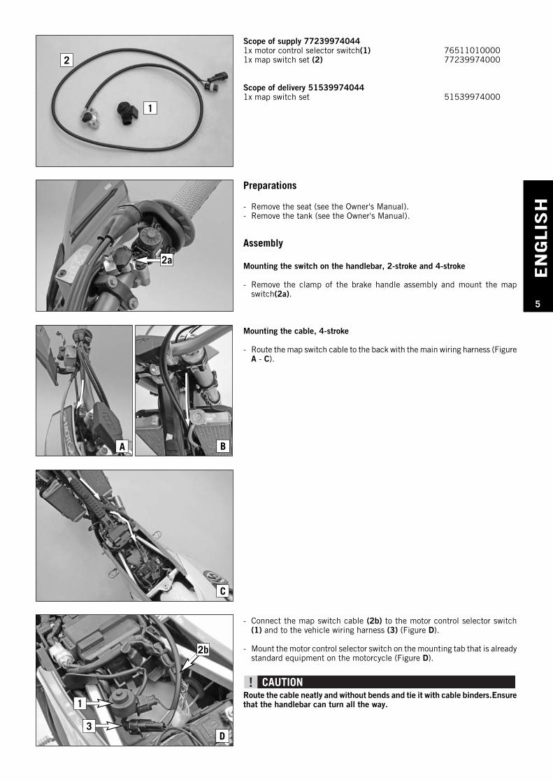
Scope of supply 772399740441x motor control selector switch(1) 765110100001x map switch set (2) 77239974000
Scope of delivery 515399740441x map switch set 51539974000
Mounting the cable, 4-stroke
- Route the map switch cable to the back with the main wiring harness (FigureA - C).
- Connect the map switch cable (2b) to the motor control selector switch(1) and to the vehicle wiring harness (3) (Figure D).
- Mount the motor control selector switch on the mounting tab that is alreadystandard equipment on the motorcycle (Figure D).
Route the cable neatly and without bends and tie it with cable binders.Ensurethat the handlebar can turn all the way.
EN
GLIS
H
6
A
B
Mounting the cable, 2-stroke
- Route the map switch cable from behind the headlight mask to behind theradiator.
Route the cable neatly and without bends and tie it with cable binders. Ensurethat the handlebar can turn all the way.
- Disconnect the plug-in connection for the ignition timing adjuster.
NOTE:The position of the plug-in connection is described in the Owner's Manualof the vehicle.
Adjustments, 2-stroke
Map switch (Figure A):
Pos. 1 -> Performance ignition timing map (height performance).Pos. 2 -> Soft ignition timing map (gentle power development).
Adjustments, 4-stroke
Map switch (Figure A):
Pos. 1 -> Standard ignition timing map.Pos. 2 -> Previously selected ignition timing map on motor control
selector switch
Motor control selector switch (Figure B):
Pos. 1 = Wet condition (gentle power development)Pos. 2 = Advanced (aggressive power development)Pos. 3, 4, 5, 6, 7, 8, 9, 0 = Standard
NOTE:If the ignition timing map is changed during a ride, it is not activated imme-diately. The selected ignition timing map does not go into effect until themotorcycle is at idle speed and the throttle is closed.
- Connect both connectors of the switch with the vacant connectors of theignition timing adjuster.
Final steps
- Mount the tank (see the Owner's Manual).- Mount the seat (see the Owner's Manual).
ITALI
AN
O
7
1
2
A B
C
D
1
3
2b
2a
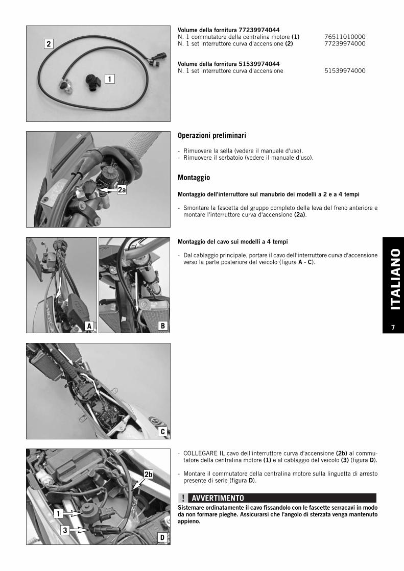
Operazioni preliminari
- Rimuovere la sella (vedere il manuale d'uso).- Rimuovere il serbatoio (vedere il manuale d'uso).
Montaggio
Montaggio dell'interruttore sul manubrio dei modelli a 2 e a 4 tempi
- Smontare la fascetta del gruppo completo della leva del freno anteriore emontare l'interruttore curva d'accensione (2a).
Volume della fornitura 77239974044N. 1 commutatore della centralina motore (1) 76511010000N. 1 set interruttore curva d'accensione (2) 77239974000
Volume della fornitura 51539974044N. 1 set interruttore curva d'accensione 51539974000
Montaggio del cavo sui modelli a 4 tempi
- Dal cablaggio principale, portare il cavo dell'interruttore curva d'accensioneverso la parte posteriore del veicolo (figura A - C).
- COLLEGARE IL cavo dell'interruttore curva d'accensione (2b) al commu-tatore della centralina motore (1) e al cablaggio del veicolo (3) (figura D).
- Montare il commutatore della centralina motore sulla linguetta di arrestopresente di serie (figura D).
Sistemare ordinatamente il cavo fissandolo con le fascette serracavi in mododa non formare pieghe. Assicurarsi che l'angolo di sterzata venga mantenutoappieno.
ITALIA
NO
8
A
B
Montaggio del cavo sui modelli a 2 tempi
- Sistemare il cavo dell'interruttore curva d'accensione dietro la mascherinaportafaro e portarlo fin dietro il radiatore.
Sistemare ordinatamente il cavo fissandolo con le fascette serracavi in mododa non formare pieghe. Assicurarsi che l'angolo di sterzata venga mantenutoappieno.
- Scollegare il connettore di regolazione della curva d'accensione
NOTA:La posizione del connettore è indicata nel manuale d'uso del veicolo.
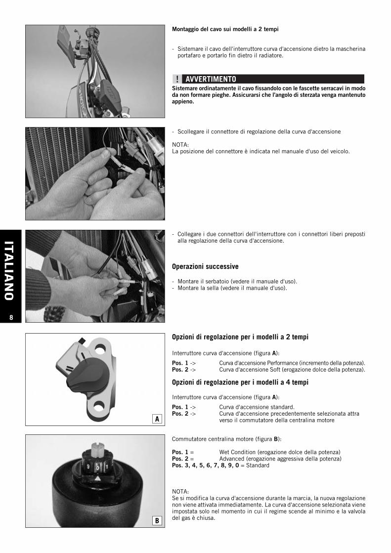
Opzioni di regolazione per i modelli a 2 tempi
Interruttore curva d'accensione (figura A):
Pos. 1 -> Curva d'accensione Performance (incremento della potenza).Pos. 2 -> Curva d'accensione Soft (erogazione dolce della potenza).
Opzioni di regolazione per i modelli a 4 tempi
Interruttore curva d'accensione (figura A):
Pos. 1 -> Curva d'accensione standard.Pos. 2 -> Curva d'accensione precedentemente selezionata attra
verso il commutatore della centralina motore
Commutatore centralina motore (figura B):
Pos. 1 = Wet Condition (erogazione dolce della potenza)Pos. 2 = Advanced (erogazione aggressiva della potenza)Pos. 3, 4, 5, 6, 7, 8, 9, 0 = Standard
NOTA:Se si modifica la curva d'accensione durante la marcia, la nuova regolazionenon viene attivata immediatamente. La curva d'accensione selezionata vieneimpostata solo nel momento in cui il regime scende al minimo e la valvoladel gas è chiusa.
- Collegare i due connettori dell'interruttore con i connettori liberi prepostialla regolazione della curva d'accensione.
Operazioni successive
- Montare il serbatoio (vedere il manuale d'uso).- Montare la sella (vedere il manuale d'uso).
FRAN
CAIS
9
1
2
A B
C
D
1
3
2b
2a
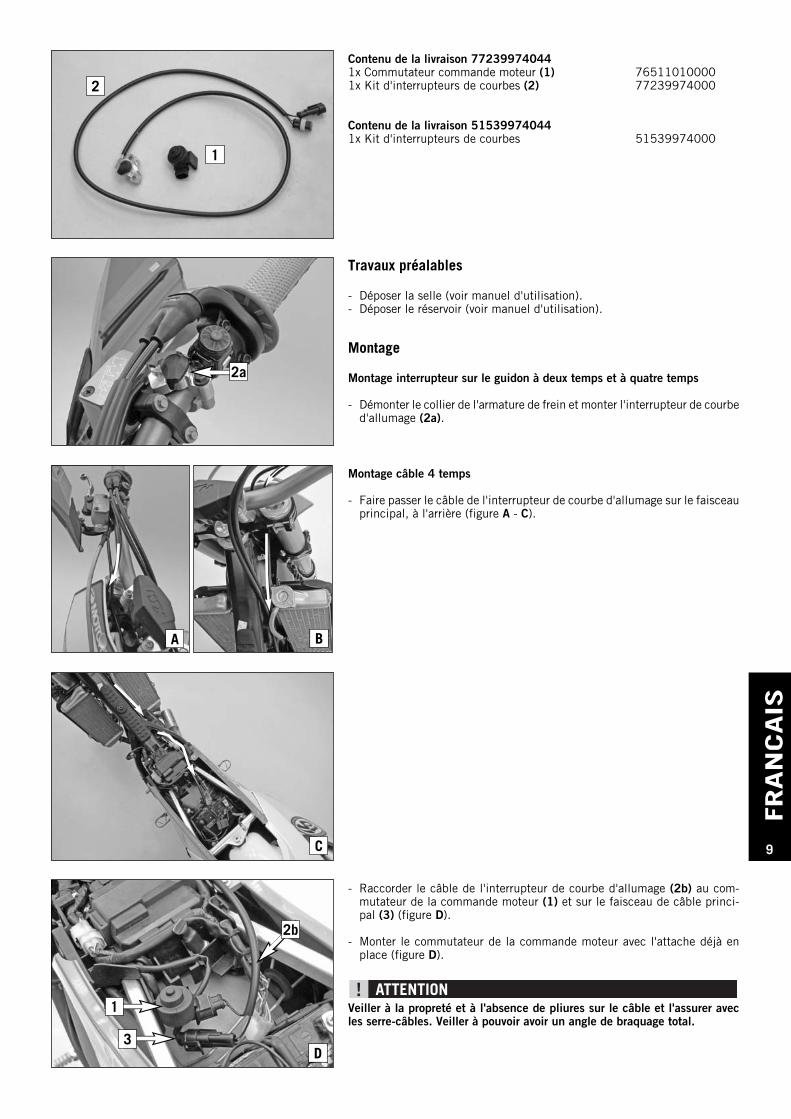
Travaux préalables
- Déposer la selle (voir manuel d'utilisation).- Déposer le réservoir (voir manuel d'utilisation).
Montage
Montage interrupteur sur le guidon à deux temps et à quatre temps
- Démonter le collier de l'armature de frein et monter l'interrupteur de courbed'allumage (2a).
Contenu de la livraison 772399740441x Commutateur commande moteur (1) 765110100001x Kit d'interrupteurs de courbes (2) 77239974000
Contenu de la livraison 515399740441x Kit d'interrupteurs de courbes 51539974000
Montage câble 4 temps
- Faire passer le câble de l'interrupteur de courbe d'allumage sur le faisceauprincipal, à l'arrière (figure A - C).
- Raccorder le câble de l'interrupteur de courbe d'allumage (2b) au com-mutateur de la commande moteur (1) et sur le faisceau de câble princi-pal (3) (figure D).
- Monter le commutateur de la commande moteur avec l'attache déjà enplace (figure D).
Veiller à la propreté et à l'absence de pliures sur le câble et l'assurer avecles serre-câbles. Veiller à pouvoir avoir un angle de braquage total.
FRAN
CAIS
10 A
B
Montage câble 2 temps
- Faire passer le câble de l'interrupteur de courbe d'allumage derrière la plaque-phare jusque derrière le radiateur.
Veiller à la propreté et à l'absence de pliures sur le câble et l'assurer avecles serre-câbles. Veiller à pouvoir avoir un angle de braquage total.
- Déconnecter la fiche de connexion du dispositif de réglage des courbesd'allumage
REMARQUE :La position de la fiche de connexion est indiquée dans le manuel d'utilisa-tion du véhicule.
Possibilités de réglage à deux temps
Interrupteur de courbes d'allumage (figure A) :
Pos. 1 -> Performance de la courbe d'allumage (puissance supérieure).Pos. 2 -> Courbe d'allumage Soft (montée en puissance en douceur).
Possibilités de réglage à quatre temps
Interrupteur de courbes d'allumage (figure A) :
Pos. 1 -> Courbe d'allumage standard.Pos. 2 -> Courbe d'allumage sélectionnée auparavant sur le
commutateur Commande moteur
Commutateur commande moteur (figure B) :
Pos. 1 = Condition Wet (montée en puissance en douceur)Pos. 2 = Advanced (montée en puissance agressive)Pos. 3, 4, 5, 6, 7, 8, 9, 0 = Standard
REMARQUE :Si la courbe d'allumage est sélectionnée en cours de conduite, elle ne serapas activée immédiatement. La courbe d'allumage sélectionnée ne sera acti-vée qu'une fois le moteur au ralenti et avec la manette d'accélération fer-mée.
- Connecter les deux connecteurs de l'interrupteur avec les fiches libres dudispositif de réglage des courbes d'allumage
Travaux ultérieurs
- Monter le réservoir (voir le manuel d'utilisation).- Monter la selle (voir manuel d'utilisation).
ESPAN
OL
11
1
2
A B
C
D
1
3
2b
2a
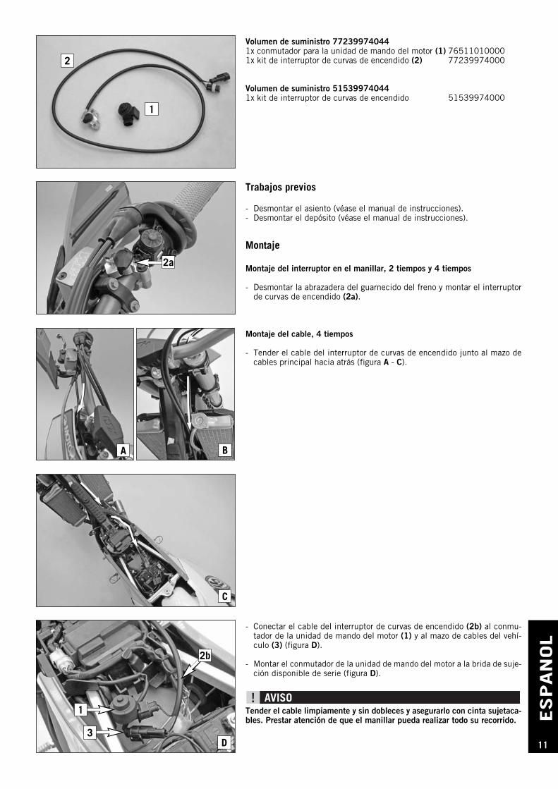
Trabajos previos
- Desmontar el asiento (véase el manual de instrucciones).- Desmontar el depósito (véase el manual de instrucciones).
Montaje
Montaje del interruptor en el manillar, 2 tiempos y 4 tiempos
- Desmontar la abrazadera del guarnecido del freno y montar el interruptorde curvas de encendido (2a).
Volumen de suministro 772399740441x conmutador para la unidad de mando del motor (1) 765110100001x kit de interruptor de curvas de encendido (2) 77239974000
Volumen de suministro 515399740441x kit de interruptor de curvas de encendido 51539974000
Montaje del cable, 4 tiempos
- Tender el cable del interruptor de curvas de encendido junto al mazo decables principal hacia atrás (figura A - C).
- Conectar el cable del interruptor de curvas de encendido (2b) al conmu-tador de la unidad de mando del motor (1) y al mazo de cables del vehí-culo (3) (figura D).
- Montar el conmutador de la unidad de mando del motor a la brida de suje-ción disponible de serie (figura D).
Tender el cable limpiamente y sin dobleces y asegurarlo con cinta sujetaca-bles. Prestar atención de que el manillar pueda realizar todo su recorrido.
ESPAN
OL
12
A
B
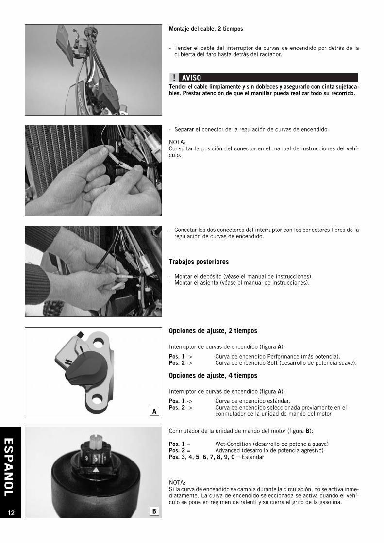
Montaje del cable, 2 tiempos
- Tender el cable del interruptor de curvas de encendido por detrás de lacubierta del faro hasta detrás del radiador.
Tender el cable limpiamente y sin dobleces y asegurarlo con cinta sujetaca-bles. Prestar atención de que el manillar pueda realizar todo su recorrido.
- Separar el conector de la regulación de curvas de encendido
NOTA:Consultar la posición del conector en el manual de instrucciones del vehí-culo.
Opciones de ajuste, 2 tiempos
Interruptor de curvas de encendido (figura A):
Pos. 1 -> Curva de encendido Performance (más potencia).Pos. 2 -> Curva de encendido Soft (desarrollo de potencia suave).
Opciones de ajuste, 4 tiempos
Interruptor de curvas de encendido (figura A):
Pos. 1 -> Curva de encendido estándar.Pos. 2 -> Curva de encendido seleccionada previamente en el
conmutador de la unidad de mando del motor
Conmutador de la unidad de mando del motor (figura B):
Pos. 1 = Wet-Condition (desarrollo de potencia suave)Pos. 2 = Advanced (desarrollo de potencia agresivo)Pos. 3, 4, 5, 6, 7, 8, 9, 0 = Estándar
NOTA:Si la curva de encendido se cambia durante la circulación, no se activa inme-diatamente. La curva de encendido seleccionada se activa cuando el vehí-culo se pone en régimen de ralentí y se cierra el grifo de la gasolina.
- Conectar los dos conectores del interruptor con los conectores libres de laregulación de curvas de encendido.
Trabajos posteriores
- Montar el depósito (véase el manual de instrucciones).- Montar el asiento (véase el manual de instrucciones).


![Membrangebundenes IL-17A und IL-17F zur Herstellung ... · Die Struktur des Zysteinknotens in den IL-17 Zytokinen wurde in IL-17F charakterisiert [31, 34]. Die Aminosäuresequenzen](https://img.pdfslide.org/doc/110x75/607a3c56ea9e763b78016a3f/membrangebundenes-il-17a-und-il-17f-zur-herstellung-die-struktur-des-zysteinknotens.jpg)