Embed Size (px)
Citation preview
isoMED427_00_M_DEEN / 04.2019
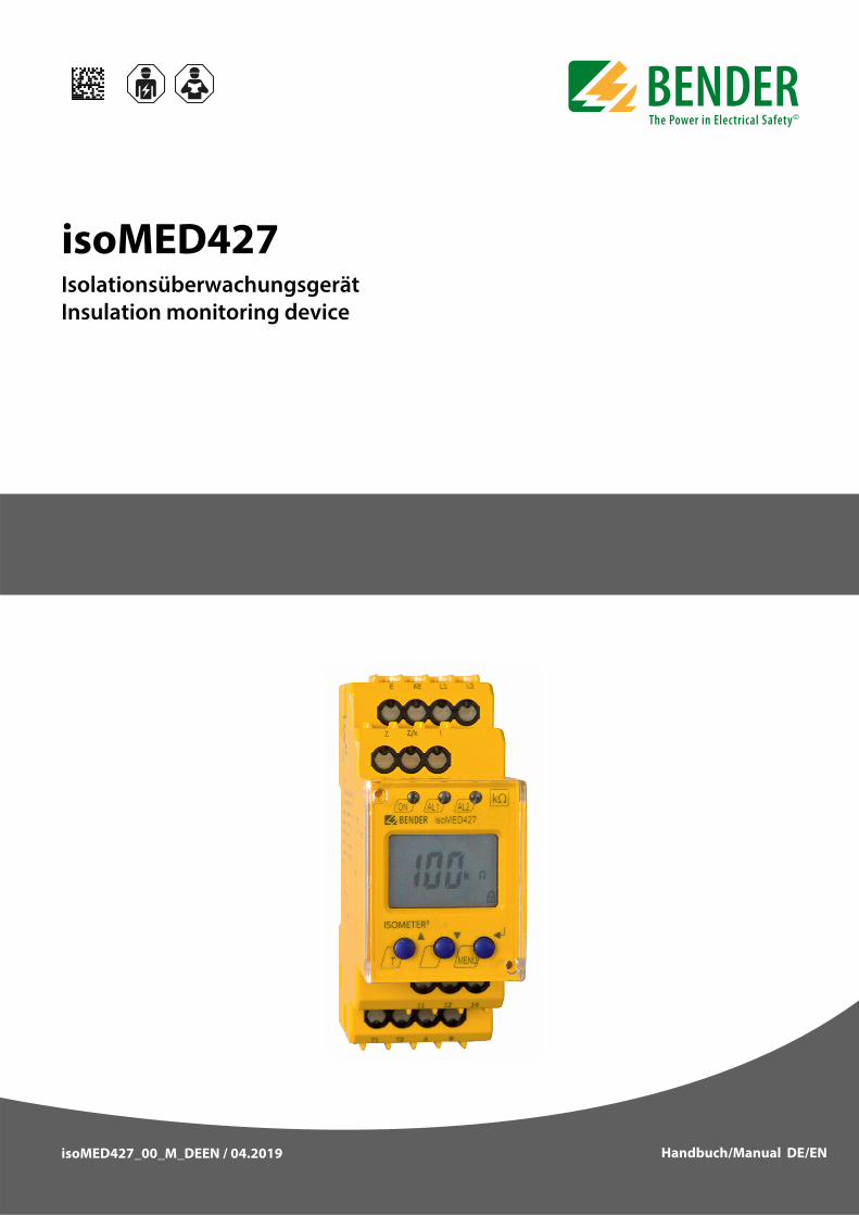
isoMED427Isolationsüberwachungsgerät Insulation monitoring device
Handbuch/Manual DE/EN
Handbuch/ManualDE EN
isoMED427
Isolationsüberwachungsgerät
Bestimmungsgemäße VerwendungDas ISOMETER® isoMED427 überwacht den IsolationswiderstandRF eines medizinischen IT-Systems mit AC 70…264 V. Zusätzlichwerden Laststrom und Temperatur des IT-System-Trafos über-wacht. Über die BMS-Schnittstelle werden Alarme und Messwerte weite-ren Busteilnehmern zur Verfügung gestellt. Zur Anzeige und Alarmierung wird die Verwendung speziellerMelde- und Prüfkombinationen empfohlen. Die Tabelle aufSeite 11 zeigt die empfohlenen Gerätekombinationen.Das isoMED427 benötigt keine zusätzliche Versorgungsspan-nung. Die maximal zulässige Netzableitkapazität Ce beträgt 5μF.
Sicherheitshinweise allgemeinBestandteil der Gerätedokumentation sind neben diesem Daten-blatt die beiliegenden „Wichtigen sicherheitstechnischen Hin-weise für Bender-Produkte“.
Sicherheitshinweise gerätespezifisch
FunktionsbeschreibungBei regulärem Betrieb zeigt das Display den aktuellen Isolations-widerstand an. Mit der Aufwärts- oder Abwärtstaste kann auf dieAnzeige des aktuellen Laststroms in % umgeschaltet werden. Unterschreitet der Isolationswiderstand den Ansprechwert, sig-nalisiert die LED AL1 einen Isolationsfehler. AL2 leuchtet bei zuhohem Laststrom sowie Übertemperatur des überwachten IT-System-Trafos. Das Alarm-Relais K1 signalisiert alle Alarmkatego-rien. Zusätzlich wird an den Klemmen A, B ein Bus-Signal für Iso-lationsfehlersuchgeräte sowie Melde- und Prüfkombinationenbereitgestellt. Das isoMED427 kann nur als BMS-Slave betrieben werden. Daherübernehmen die Meldekombination bzw. das Isolationsfehler-suchgerät die Master-Funktion. BMS-Master haben stets die BMS-Adresse 1.
Selbsttest, automatischDas Gerät führt nach dem Zuschalten der Versorgungsspannungund danach stündlich einen Selbsttest durch, bei dem interneFunktionsstörungen oder Anschlussfehler ermittelt und als Feh-lercode auf dem Display angezeigt werden. Das Alarm-Relais wirddabei nicht umgeschaltet.
Gefahr vor Sachschaden durch unsachgemäße Installation! Die Anlage kann Schaden nehmen, wenn Sie ineinem leitend verbundenen System mehr als einIsolationsüberwachungsgerät anschließen. Sindmehrere Geräte angeschlossen, funktioniert dasGerät nicht und meldet keine Isolationsfehler.Schließen Sie in jedem leitend verbundenenSystem nur ein Isolationsüberwachungsgerät an.
Trennung vom IT-System beachten!Vor Isolations- und Spannungsprüfungen an derAnlage muss das Isolationsüberwachungsgerät fürdie Dauer der Prüfung vom IT-System getrenntsein. Andernfalls kann das Gerät Schaden nehmen.
VORSICHT
VORSICHT
DE
isoMED427_D00394_00_M_DEEN / 04.2019
Insulation monitoring device
Intended useThe ISOMETER® isoMED427 monitors the insulation resistance RFin medical IT systems of AC 70…264 V. In addition, the IT systemtransformer's load current and temperature are monitored.
Alarms and measured values are made available to other bus de-vices via the BMS interface. For alarm and status indication the use of special alarm indicatorand test combinations is recommended. Recommended devicecombinations are listed in the table on page 11.The isoMED427 does not require separate supply voltage. Themaximum permissible system leakage capacitance Ce is 5μF.
General safety informationIn addition to this data sheet, the documentation of the device in-cludes a sheet entitled "Important safety instructions for Benderproducts“.
Device-specific safety information
FunctionIn normal operation, the display indicates the currently measuredinsulation resistance value. The Up and Down buttons are used toselect the display indication of the currently measured load cur-rent in percentages. If the insulation resistance falls below the re-sponse value, LED AL1 will signal an insulation fault. LED AL2lights when the load current is too high and when the tempera-ture of the monitored IT system transformer is exceeded, alarmrelay K1 signals all types of alarms. In addition, a bus signal is pro-vided across the terminals A, B for insulation fault locators andalarm indicator and test combinations. The isoMED427 can only be operated as BMS slave. That is whythe alarm indicator or the insulation fault locator operates as theMaster. BMS address 1 must always be assigned to the BMSmaster.
Automatic self testThe device automatically carries out a self test after connecting tothe supply voltage and later every hour. During the self test inter-nal functional faults or connection faults will be determined andwill appear in form of an error code on the display. The alarm relayis not switched over during this test.
Risk of property damage due to unprofession-al installation! If more than one insulation monitoring device isconnected to a conductively connected system,the system can be damaged. If several devices areconnected, the device does not function and doesnot signal insulation faults. Make sure that onlyone insulation monitoring device is connected ineach conductively connected system.
Ensure disconnection from the IT system!When insulation or voltage tests are to be carriedout, the device shall be isolated from the systemfor the test period. Otherwise the device may bedamaged.
CAUTION
CAUTION
EN
2
isoMED427_D00394_00_M_DEEN / 04.2019
isoMED427
.
Manual self testAfter pressing the internal or the external test button for > 2 s, thedevice carries out a self test. During this test, internal functionalfaults, or connection faults will be determined and will appear inform of an error code on the display. The alarm relay will beswitched during this test.Whilst the test button "T" is pressed, all display elements availablefor this device are shown.
Functional faultsIn case of a malfunction, the relay K1 (11, 12, 14) and all of thethree LEDs flash. An error code appears on the display.E01 = PE connection fault, no low-resistance connection between E and KE.E03 =Measuring current transformer interruptionE04 =Short-circuit measuring current transformerE05…Exx = Internal device error, contact the Bender service.
Password protection
If password protection has been activated (on), settings can onlybe made subject to the correct password being entered (0…999).
Factory setting FACAfter activating the factory setting, all settings previouslychanged are reset to delivery status.
Monitoring the IT system transformerThe device monitors the temperature by evaluating the resist-ance value of a PTC. When a response value of 4 kΩ is reached, analarm will be activated indicating overtemperature, the displayshows > °C. Temperature values will not be indicated.
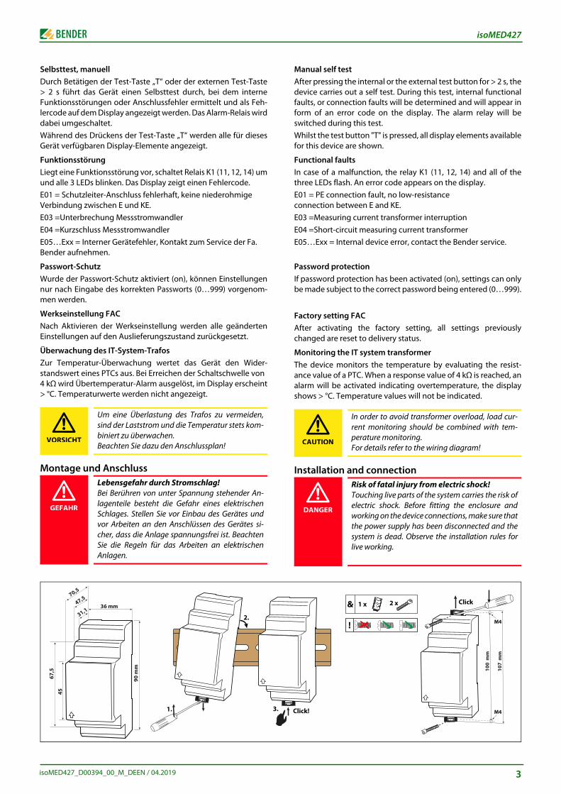
Installation and connection
In order to avoid transformer overload, load cur-rent monitoring should be combined with tem-perature monitoring.For details refer to the wiring diagram!
Risk of fatal injury from electric shock!Touching live parts of the system carries the risk ofelectric shock. Before fitting the enclosure andworking on the device connections, make sure thatthe power supply has been disconnected and thesystem is dead. Observe the installation rules forlive working.
CAUTION
DANGER
Click!
& 2 x1 x
100
mm
107
mm
Click
M4
M4!
Selbsttest, manuellDurch Betätigen der Test-Taste „T“ oder der externen Test-Taste> 2 s führt das Gerät einen Selbsttest durch, bei dem interneFunktionsstörungen oder Anschlussfehler ermittelt und als Feh-lercode auf dem Display angezeigt werden. Das Alarm-Relais wirddabei umgeschaltet.Während des Drückens der Test-Taste „T“ werden alle für diesesGerät verfügbaren Display-Elemente angezeigt.
FunktionsstörungLiegt eine Funktionsstörung vor, schaltet Relais K1 (11, 12, 14) umund alle 3 LEDs blinken. Das Display zeigt einen Fehlercode.E01 = Schutzleiter-Anschluss fehlerhaft, keine niederohmige Verbindung zwischen E und KE.E03 =Unterbrechung MessstromwandlerE04 =Kurzschluss MessstromwandlerE05…Exx = Interner Gerätefehler, Kontakt zum Service der Fa. Bender aufnehmen.
Passwort-Schutz Wurde der Passwort-Schutz aktiviert (on), können Einstellungennur nach Eingabe des korrekten Passworts (0…999) vorgenom-men werden.
Werkseinstellung FACNach Aktivieren der Werkseinstellung werden alle geändertenEinstellungen auf den Auslieferungszustand zurückgesetzt.
Überwachung des IT-System-TrafosZur Temperatur-Überwachung wertet das Gerät den Wider-standswert eines PTCs aus. Bei Erreichen der Schaltschwelle von 4 kΩ wird Übertemperatur-Alarm ausgelöst, im Display erscheint> °C. Temperaturwerte werden nicht angezeigt.
Montage und Anschluss
Um eine Überlastung des Trafos zu vermeiden,sind der Laststrom und die Temperatur stets kom-biniert zu überwachen.Beachten Sie dazu den Anschlussplan!
Lebensgefahr durch Stromschlag!Bei Berühren von unter Spannung stehender An-lagenteile besteht die Gefahr eines elektrischenSchlages. Stellen Sie vor Einbau des Gerätes undvor Arbeiten an den Anschlüssen des Gerätes si-cher, dass die Anlage spannungsfrei ist. BeachtenSie die Regeln für das Arbeiten an elektrischenAnlagen.
VORSICHT
GEFAHR
����
�
���
�
�����
���
��
��
1.
2.
3
3
4
isoMED427
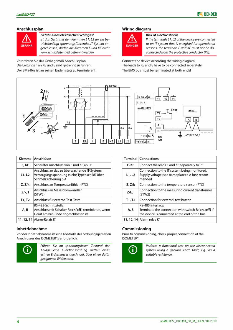
Wiring diagram
Connect the device according the wiring diagram.The leads to KE and E have to be connected separately!The BMS bus must be terminated at both ends!
CommissioningPrior to commissioning, check proper connection of the ISOMETER®.
Risk of electric shock!If the terminals L1, L2 of the device are connectedto an IT system that is energised for operationalreasons, the terminals E and KE must not be dis-connected from the protective conductor (PE).
Terminal Connections
E, KE Connect the leads E and KE separately to PE
L1, L2Connection to the IT system being monitored.Supply voltage (see nameplate) 6 A fuse recom-mended
Z, Z/k Connection to the temperature sensor (PTC)
Z/k, lConnection to the measuring current transformer (STW2)
T1, T2 Connection for external test button
A, BRS-485 interface, Terminate the connection with switch R (on, off) if the device is connected at the end of the bus.
11, 12, 14 Alarm relay K1
Perform a functional test on the disconnectedsystem using a genuine earth fault, e.g. via asuitable resistance.
DANGER
Anschlussplan
Verdrahten Sie das Gerät gemäß Anschlussplan.Die Leitungen an KE und E sind getrennt zu führen!Der BMS-Bus ist an seinen Enden stets zu terminieren!
InbetriebnahmeVor der Inbetriebnahme ist eine Kontrolle des ordnungsgemäßenAnschlusses des ISOMETER®s erforderlich.
Gefahr eines elektrischen Schlages!Ist das Gerät mit den Klemmen L1, L2 an ein be-triebsbedingt spannungsführendes IT-System an-geschlossen, dürfen die Klemmen E und KE nichtvom Schutzleiter (PE) getrennt werden
Klemme Anschlüsse
E, KE Separater Anschluss von E und KE an PE
L1, L2Anschluss an das zu überwachende IT-System;Versorgungsspannung (siehe Typenschild) über Schmelzsicherung 6 A
Z, Z/k Anschluss an Temperaturfühler (PTC)
Z/k, lAnschluss an Messstromwandler (STW2)
T1, T2 Anschluss für externe Test-Taste
A, BRS-485-Schnittstelle, Anschluss mit Schalter R (on/off) terminieren, wenn Gerät am Bus-Ende angeschlossen ist
11, 12, 14 Alarm-Relais K1
Führen Sie im spannungslosen Zustand derAnlage eine Funktionsprüfung mittels einesechten Erdschlusses durch, ggf. über einen dafürgeeigneten Widerstand.
GEFAHR
�
�
�
isoMED427_D00394_00_M_DEEN / 04.2019
isoMED427_D00394_00_M_DEEN / 04.2019
isoMED427
teff th
1
LL
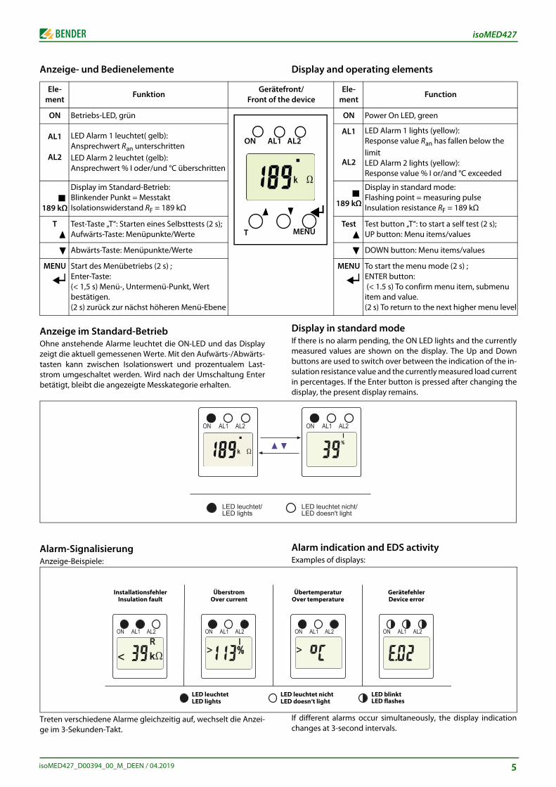
Display and operating elements
Display in standard modeIf there is no alarm pending, the ON LED lights and the currentlymeasured values are shown on the display. The Up and Downbuttons are used to switch over between the indication of the in-sulation resistance value and the currently measured load currentin percentages. If the Enter button is pressed after changing thedisplay, the present display remains.
Alarm indication and EDS activityExamples of displays:
If different alarms occur simultaneously, the display indicationchanges at 3-second intervals.
ront/e device
Ele-ment
Function
ON Power On LED, green
AL1
AL2
LED Alarm 1 lights (yellow): Response value Ran has fallen below the limitLED Alarm 2 lights (yellow): Response value % I or/and °C exceeded
189 kΩ
Display in standard mode: Flashing point = measuring pulseInsulation resistance RF = 189 kΩ
Test Test button „T“: to start a self test (2 s); UP button: Menu items/values
DOWN button: Menu items/values
MENU To start the menu mode (2 s) ;ENTER button: (< 1.5 s) To confirm menu item, submenu item and value. (2 s) To return to the next higher menu level
AL2
MENU
�
������������ ��������������� ��
�� ��� ���
ED leuchtet nichtED doesn‘t light
LED blinktLED flashes
ÜbertemperaturOver temperature
GerätefehlerDevice error
Anzeige- und Bedienelemente
Anzeige im Standard-BetriebOhne anstehende Alarme leuchtet die ON-LED und das Displayzeigt die aktuell gemessenen Werte. Mit den Aufwärts-/Abwärts-tasten kann zwischen Isolationswert und prozentualem Last-strom umgeschaltet werden. Wird nach der Umschaltung Enterbetätigt, bleibt die angezeigte Messkategorie erhalten.
Alarm-SignalisierungAnzeige-Beispiele:
Treten verschiedene Alarme gleichzeitig auf, wechselt die Anzei-ge im 3-Sekunden-Takt.
Ele-ment
FunktionGerä
Front o
ON Betriebs-LED, grün
AL1
AL2
LED Alarm 1 leuchtet( gelb): Ansprechwert Ran unterschrittenLED Alarm 2 leuchtet (gelb): Ansprechwert % I oder/und °C überschritten
189 kΩ
Display im Standard-Betrieb: Blinkender Punkt = MesstaktIsolationswiderstand RF = 189 kΩ
T Test-Taste „T“: Starten eines Selbsttests (2 s); Aufwärts-Taste: Menüpunkte/Werte
Abwärts-Taste: Menüpunkte/Werte
MENU Start des Menübetriebs (2 s) ;Enter-Taste:(< 1,5 s) Menü-, Untermenü-Punkt, Wert bestätigen. (2 s) zurück zur nächst höheren Menü-Ebene
ON AL
T
���������������� ���
�� ��� ���
LED leuchtetLED lights
InstallationsfehlerInsulation fault
ÜberstromOver current
5
6
isoMED427
/ M
���
���
���
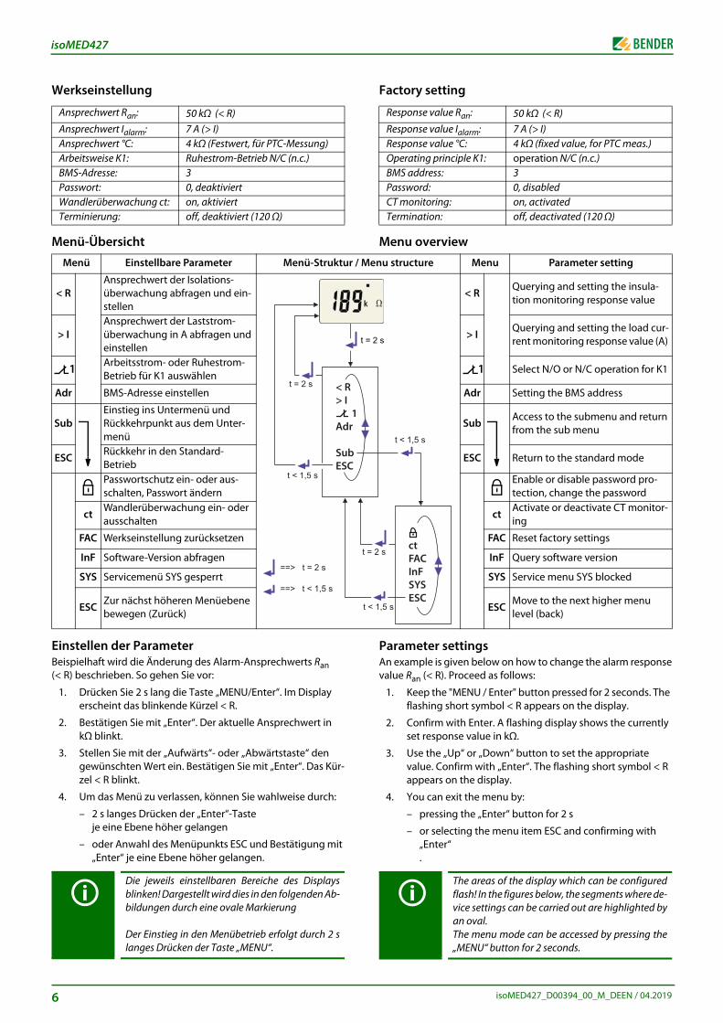
Factory setting
Menu overview
Parameter settingsAn example is given below on how to change the alarm responsevalue Ran (< R). Proceed as follows:
1. Keep the "MENU / Enter" button pressed for 2 seconds. The flashing short symbol < R appears on the display.
2. Confirm with Enter. A flashing display shows the currently set response value in kΩ.
3. Use the „Up“ or „Down“ button to set the appropriate value. Confirm with „Enter“. The flashing short symbol < R appears on the display.
4. You can exit the menu by:
– pressing the „Enter“ button for 2 s
– or selecting the menu item ESC and confirming with „Enter“.
Response value Ran: 50 kΩ (< R)Response value Ialarm: 7 A (> I)Response value °C: 4 kΩ (fixed value, for PTC meas.)Operating principle K1: operation N/C (n.c.)BMS address: 3Password: 0, disabledCT monitoring: on, activatedTermination: off, deactivated (120 Ω)
The areas of the display which can be configuredflash! In the figures below, the segments where de-vice settings can be carried out are highlighted byan oval. The menu mode can be accessed by pressing the„MENU“ button for 2 seconds.
enu structure Menu Parameter setting
< RQuerying and setting the insula-tion monitoring response value
> IQuerying and setting the load cur-rent monitoring response value (A)
1 Select N/O or N/C operation for K1
Adr Setting the BMS address
Sub Access to the submenu and return from the sub menu
ESC Return to the standard mode
Enable or disable password pro-tection, change the password
ctActivate or deactivate CT monitor-ing
FAC Reset factory settings
InF Query software version
SYS Service menu SYS blocked
ESCMove to the next higher menu level (back)
����
���������
���� ����
������
����
Werkseinstellung
Menü-Übersicht
Einstellen der ParameterBeispielhaft wird die Änderung des Alarm-Ansprechwerts Ran (< R) beschrieben. So gehen Sie vor:
1. Drücken Sie 2 s lang die Taste „MENU/Enter“. Im Display erscheint das blinkende Kürzel < R.
2. Bestätigen Sie mit „Enter“. Der aktuelle Ansprechwert in kΩ blinkt.
3. Stellen Sie mit der „Aufwärts“- oder „Abwärtstaste“ den gewünschten Wert ein. Bestätigen Sie mit „Enter“. Das Kür-zel < R blinkt.
4. Um das Menü zu verlassen, können Sie wahlweise durch:
– 2 s langes Drücken der „Enter“-Taste je eine Ebene höher gelangen
– oder Anwahl des Menüpunkts ESC und Bestätigung mit „Enter“ je eine Ebene höher gelangen.
Ansprechwert Ran: 50 kΩ (< R)Ansprechwert Ialarm: 7 A (> I)Ansprechwert °C: 4 kΩ (Festwert, für PTC-Messung)Arbeitsweise K1: Ruhestrom-Betrieb N/C (n.c.)BMS-Adresse: 3Passwort: 0, deaktiviertWandlerüberwachung ct: on, aktiviertTerminierung: off, deaktiviert (120 Ω)
Menü Einstellbare Parameter Menü-Struktur
< RAnsprechwert der Isolations-überwachung abfragen und ein-stellen
> IAnsprechwert der Laststrom-überwachung in A abfragen und einstellen
1 Arbeitsstrom- oder Ruhestrom-Betrieb für K1 auswählen
Adr BMS-Adresse einstellen
SubEinstieg ins Untermenü und Rückkehrpunkt aus dem Unter-menü
ESC Rückkehr in den Standard-BetriebPasswortschutz ein- oder aus-schalten, Passwort ändern
ctWandlerüberwachung ein- oder ausschalten
FAC Werkseinstellung zurücksetzen
InF Software-Version abfragen
SYS Servicemenü SYS gesperrt
ESCZur nächst höheren Menüebene bewegen (Zurück)
Die jeweils einstellbaren Bereiche des Displaysblinken! Dargestellt wird dies in den folgenden Ab-bildungen durch eine ovale Markierung
Der Einstieg in den Menübetrieb erfolgt durch 2 slanges Drücken der Taste „MENU“.
���������
�������
�������������
��������������������
���������������
isoMED427_D00394_00_M_DEEN / 04.2019
isoMED427_D00394_00_M_DEEN / 04.2019
isoMED427
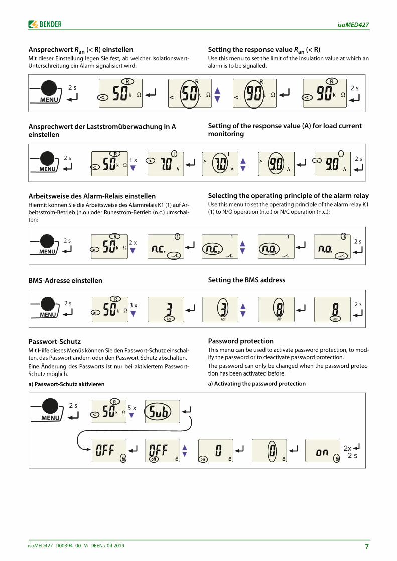
Setting the response value Ran (< R)Use this menu to set the limit of the insulation value at which analarm is to be signalled.
Setting of the response value (A) for load current monitoring
Selecting the operating principle of the alarm relayUse this menu to set the operating principle of the alarm relay K1(1) to N/O operation (n.o.) or N/C operation (n.c.):
Setting the BMS address
Password protection This menu can be used to activate password protection, to mod-ify the password or to deactivate password protection. The password can only be changed when the password protec-tion has been activated before.
a) Activating the password protection
�����
�����
�����
�����
�������
Ansprechwert Ran (< R) einstellenMit dieser Einstellung legen Sie fest, ab welcher Isolationswert-Unterschreitung ein Alarm signalisiert wird.
Ansprechwert der Laststromüberwachung in A einstellen
Arbeitsweise des Alarm-Relais einstellenHiermit können Sie die Arbeitsweise des Alarmrelais K1 (1) auf Ar-beitsstrom-Betrieb (n.o.) oder Ruhestrom-Betrieb (n.c.) umschal-ten:
BMS-Adresse einstellen
Passwort-Schutz Mit Hilfe dieses Menüs können Sie den Passwort-Schutz einschal-ten, das Passwort ändern oder den Passwort-Schutz abschalten. Eine Änderung des Passworts ist nur bei aktiviertem Passwort-Schutz möglich.
a) Passwort-Schutz aktivieren
�����
���
�����
���
���
�����
���
���
�����
���
���
�����
���
���
7
isoMED427
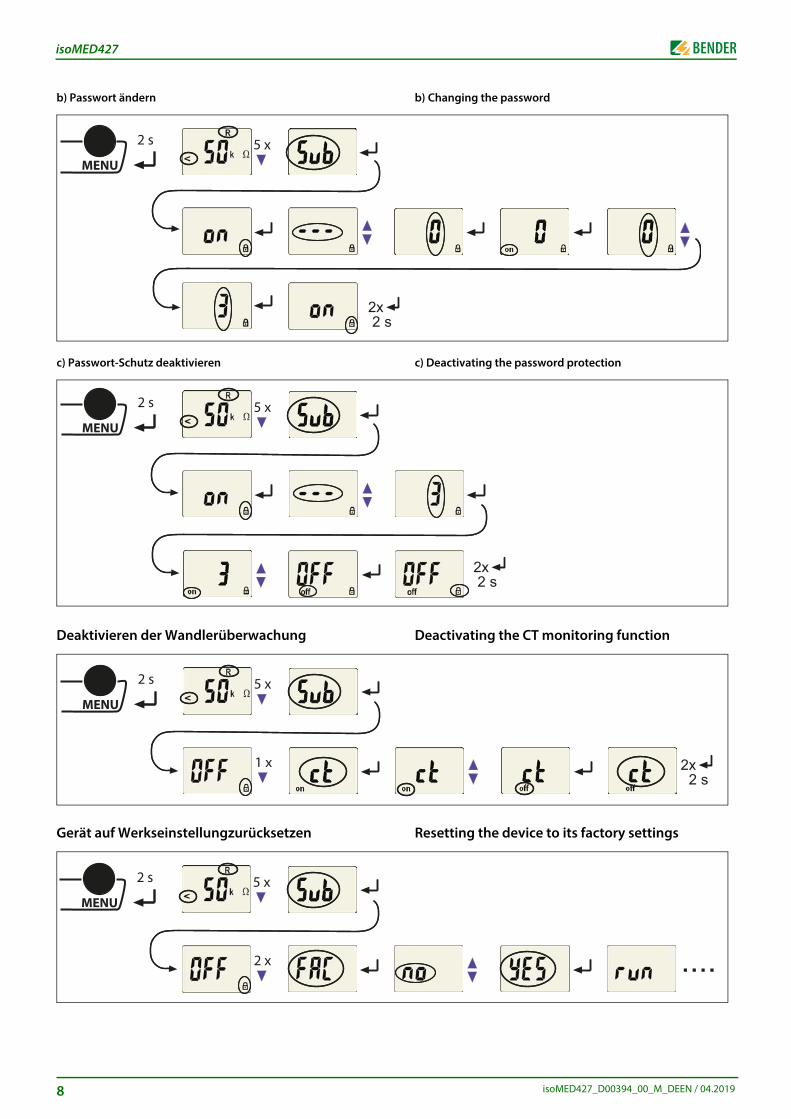
b) Passwort ändern
c) Passwort-Schutz deaktivieren
Deaktivieren der Wandlerüberwachung
Gerät auf Werkseinstellungzurücksetzen
�����
���
������
���
�����
���
���
�����
���
���
���
�����
���
���
���
8
������
�������
����
b) Changing the password
c) Deactivating the password protection
Deactivating the CT monitoring function
Resetting the device to its factory settings
isoMED427_D00394_00_M_DEEN / 04.2019
isoMED427
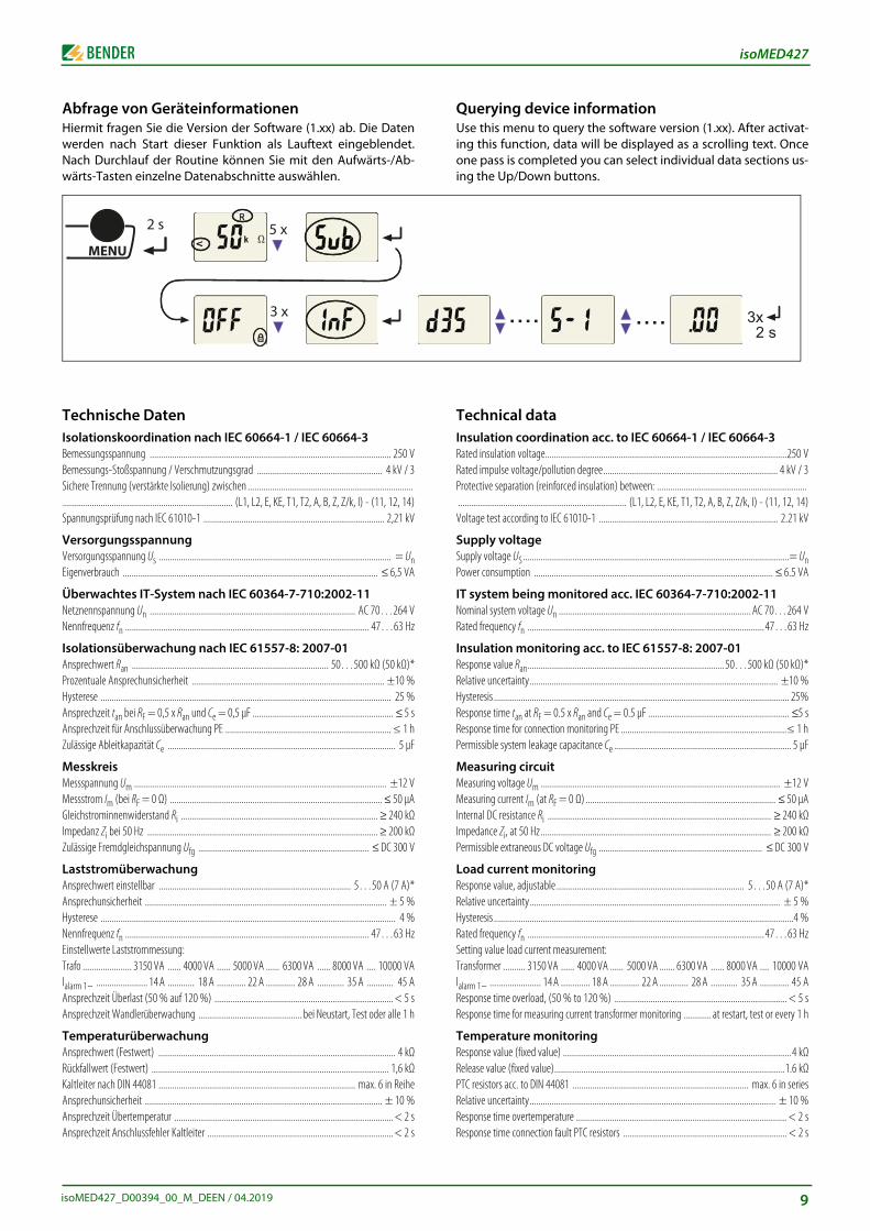
Abfrage von GeräteinformationenHiermit fragen Sie die Version der Software (1.xx) ab. Die Datenwerden nach Start dieser Funktion als Lauftext eingeblendet.Nach Durchlauf der Routine können Sie mit den Aufwärts-/Ab-wärts-Tasten einzelne Datenabschnitte auswählen.
Technische DatenIsolationskoordination nach IEC 60664-1 / IEC 60664-3Bemessungsspannung ............................................................................................................ 250 VBemessungs-Stoßspannung / Verschmutzungsgrad ........................................................ 4 kV / 3Sichere Trennung (verstärkte Isolierung) zwischen ...................................................................................................................................................... (L1, L2, E, KE, T1, T2, A, B, Z, Z/k, I) - (11, 12, 14)Spannungsprüfung nach IEC 61010-1 ................................................................................. 2,21 kV
VersorgungsspannungVersorgungsspannung Us ........................................................................................................ = UnEigenverbrauch .................................................................................................................. ≤ 6,5 VA
Überwachtes IT-System nach IEC 60364-7-710:2002-11Netznennspannung Un ............................................................................................ AC 70…264 VNennfrequenz fn ............................................................................................................. 47…63 Hz
Isolationsüberwachung nach IEC 61557-8: 2007-01Ansprechwert Ran ........................................................................................ 50…500 kΩ (50 kΩ)*Prozentuale Ansprechunsicherheit ...................................................................................... ±10 %Hysterese .................................................................................................................................. 25 %Ansprechzeit tan bei RF = 0,5 x Ran und Ce = 0,5 μF ............................................................... ≤ 5 sAnsprechzeit für Anschlussüberwachung PE .......................................................................... ≤ 1 hZulässige Ableitkapazität Ce ...................................................................................................... 5 μF
MesskreisMessspannung Um ................................................................................................................. ±12 VMessstrom Im (bei RF = 0 Ω) ............................................................................................... ≤ 50 μAGleichstrominnenwiderstand Ri ........................................................................................ ≥ 240 kΩImpedanz Zi bei 50 Hz ....................................................................................................... ≥ 200 kΩZulässige Fremdgleichspannung Ufg ............................................................................ ≤ DC 300 V
LaststromüberwachungAnsprechwert einstellbar ...................................................................................... 5…50 A (7 A)*Ansprechunsicherheit ............................................................................................................ ± 5 %Hysterese .................................................................................................................................... 4 %Nennfrequenz fn ............................................................................................................. 47…63 HzEinstellwerte Laststrommessung:Trafo ...................... 3150 VA ...... 4000 VA ...... 5000 VA ...... 6300 VA ...... 8000 VA .... 10000 VAIalarm 1~ ....................... 14 A ............ 18 A ............. 22 A ............. 28 A ............ 35 A ............ 45 AAnsprechzeit Überlast (50 % auf 120 %) ................................................................................ < 5 sAnsprechzeit Wandlerüberwachung .............................................. bei Neustart, Test oder alle 1 h
TemperaturüberwachungAnsprechwert (Festwert) .......................................................................................................... 4 kΩRückfallwert (Festwert) .......................................................................................................... 1,6 kΩKaltleiter nach DIN 44081 ........................................................................................ max. 6 in ReiheAnsprechunsicherheit .......................................................................................................... ± 10 %Ansprechzeit Übertemperatur .................................................................................................. < 2 sAnsprechzeit Anschlussfehler Kaltleiter ................................................................................... < 2 s
�����
���
���
���
isoMED427_D00394_00_M_DEEN / 04.2019
���� ���� �������
Querying device informationUse this menu to query the software version (1.xx). After activat-ing this function, data will be displayed as a scrolling text. Onceone pass is completed you can select individual data sections us-ing the Up/Down buttons.
Technical dataInsulation coordination acc. to IEC 60664-1 / IEC 60664-3Rated insulation voltage............................................................................................................250 VRated impulse voltage/pollution degree.............................................................................. 4 kV / 3Protective separation (reinforced insulation) between: .............................................................................................................................................. (L1, L2, E, KE, T1, T2, A, B, Z, Z/k, I) - (11, 12, 14)Voltage test according to IEC 61010-1 ................................................................................ 2.21 kV
Supply voltageSupply voltage US .......................................................................................................................= UnPower consumption ........................................................................................................... ≤ 6.5 VA
IT system being monitored acc. IEC 60364-7-710:2002-11Nominal system voltage Un ...................................................................................... AC 70…264 VRated frequency fn ..........................................................................................................47…63 Hz
Insulation monitoring acc. to IEC 61557-8: 2007-01Response value Ran........................................................................................50…500 kΩ (50 kΩ)*Relative uncertainty............................................................................................................... ±10 %Hysteresis .................................................................................................................................... 25%Response time tan at RF = 0.5 x Ran and Ce = 0.5 μF ............................................................... ≤5 sResponse time for connection monitoring PE ..........................................................................≤ 1 hPermissible system leakage capacitance Ce ............................................................................... 5 μF
Measuring circuitMeasuring voltage Um ........................................................................................................... ±12 VMeasuring current Im (at RF = 0 Ω) ..................................................................................... ≤ 50 μAInternal DC resistance Ri .................................................................................................... ≥ 240 kΩImpedance Zi, at 50 Hz....................................................................................................... ≥ 200 kΩPermissible extraneous DC voltage Ufg ......................................................................... ≤ DC 300 V
Load current monitoringResponse value, adjustable .................................................................................... 5…50 A (7 A)*Relative uncertainty................................................................................................................ ± 5 %Hysteresis ......................................................................................................................................4 %Rated frequency fn ..........................................................................................................47…63 HzSetting value load current measurement:Transformer .......... 3150 VA ...... 4000 VA ...... 5000 VA ....... 6300 VA ...... 8000 VA .... 10000 VAIalarm 1~ ....................... 14 A ............. 18 A ............. 22 A ............. 28 A ............ 35 A ............. 45 AResponse time overload, (50 % to 120 %) ............................................................................. < 5 sResponse time for measuring current transformer monitoring ............ at restart, test or every 1 h
Temperature monitoringResponse value (fixed value) ......................................................................................................4 kΩRelease value (fixed value).......................................................................................................1.6 kΩPTC resistors acc. to DIN 44081 ............................................................................... max. 6 in seriesRelative uncertainty.............................................................................................................. ± 10 %Response time overtemperature .............................................................................................. < 2 sResponse time connection fault PTC resistors ......................................................................... < 2 s
9
isoMED427
Anzeigen, SpeicherAnzeige LC-Display .......................................................................... multifunktional, unbeleuchtetMesswert Isolationswiderstand ................................................................................ 10 kΩ…1 MΩBetriebsmessunsicherheit ...................................................................................... ± 10 %, ± 2 kΩMesswert Laststrom (in % vom eingestellten Ansprechwert) .............................. 10 %…199 %Betriebsmessunsicherheit ....................................................................................... ± 5 %, ± 0,2 APasswort ................................................................................................. on, off / 0…999 (off, 0)*
SchnittstelleSchnittstelle/Protokoll ............................................................................................... RS-485 / BMSBaudrate ............................................................................................................................ 9,6 kBit/sLeitungslänge .............................................................................................................. 0…1200 mLeitung (paarweise verdrillt, geschirmt, Schirm einseitig an PE) ..................................................... ................................................................................................... empfohlen J-Y(St)Y min. n x 2 x 0,8Abschlusswiderstand .................................................................. 120 Ω (0,25 W), intern, schaltbarGeräteadresse, BMS-Bus .............................................................................................. 2…90 (3)*
Schnittstellen für Messstromwandler STW2 und Temperatur-fühlerLeitungslängen:Einzeldraht > 0,5 mm² ........................................................................................................... ≤ 1 mEinzeldraht, verdrillt > 0,5 mm² .......................................................................................... ≤ 10 mPaarweise verdrillt, geschirmt > 0,5 mm² .......................................................................... ≤ 40 mEmpfohlene Leitung .................................................. min. J-Y(St)Y 2x0,6; Schirm einseitig an PE
SchaltgliederAnzahl ............................................................................................................................. 1 WechslerArbeitsweise ................................................................... Ruhestrom / Arbeitsstrom (Ruhestrom)*Elektrische Lebensdauer bei Bemessungsbedingungen ................................. 10.000 SchaltspieleKontaktdaten nach IEC 60947-5-1Gebrauchskategorie ..................................... AC-13 ...... AC-14 ....... DC-12 ...... DC-12 ....... DC-12Bemessungsbetriebsspannung .................... 230 V ....... 230 V .......... 24 V ....... 110 V ....... 220 VBemessungsbetriebsstrom ............................... 5 A ........... 3 A ............ 1 A ........ 0,2 A ........ 0,1 AMinimale Kontaktbelastbarkeit ................................................................... 1 mA bei AC / DC 10 V
Umwelt / EMVEMV ........................................................................................................................... IEC 61326-2-4Arbeitstemperatur ............................................................................................... -25 °C…+55 °CKlimaklassen nach IEC 60721:Ortsfester Einsatz (IEC 60721-3-3) ..................................... 3K5 (ohne Betauung und Eisbildung)Transport (IEC 60721-3-2) ................................................ 2K11 (ohne Betauung und Eisbildung)Langzeitlagerung (IEC 60721-3-1) ................................... 1K22 (ohne Betauung und Eisbildung)Mechanische Beanspruchung nach IEC 60721:Ortsfester Einsatz (IEC 60721-3-3) .......................................................................................... 3M4Transport (IEC 60721-3-2) ....................................................................................................... 2M4Langzeitlagerung (IEC 60721-3-1) ........................................................................................ 1M12
AnschlussAnschlussart.......................................................................................................... FederklemmenAnschlussvermögen:starr .............................................................................................. 0,2…2,5 mm2 (AWG 24…14)flexibel ohne Aderendhülse ...................................................... 0,75…2,5 mm2 (AWG 19…14)flexibel mit Aderendhülse ........................................................... 0,2…1,5 mm2 (AWG 24…16)Abisolierlänge ........................................................................................................................ 10 mmÖffnungskraft ............................................................................................................................ 50 NTestöffnung, Durchmesser ................................................................................................... 2,1 mm
SonstigesBetriebsart .................................................................................................................... DauerbetriebGebrauchslage ..................................................................................................................... beliebigSchutzart Einbauten ........................................................................................ (DIN EN 60529) IP30Schutzart Klemmen ........................................................................................ (DIN EN 60529) IP20Gehäusematerial ......................................................................................................... PolycarbonatEntflammbarkeitsklasse ..................................................................................................... UL94V-0Schraubbefestigung ............................................................................................................... 2 x M4Schnellbefestigung auf Hutprofilschiene ......................................................................... IEC 60715Software-Version ............................................................................................................. D643 V1.0xGewicht .................................................................................................................................... 150 g( )* = Werkseinstellung
10
Displays, memoryLC display....................................................................................... multifunctional, not illuminatedMeasured value insulation resistance........................................................................10 kΩ…1 MΩOperating uncertainty ............................................................................................. ± 10 %, ± 2 kΩMeasured value load current (as % of the set response value) ............................. 10 %…199 %Operating uncertainty ............................................................................................ ± 5 %, ± 0.2 APassword.................................................................................................. on, off / 0…999 (off, 0)*
InterfaceInterface/protocol........................................................................................................RS-485 / BMSBaud rate .......................................................................................................................... 9.6 kbit / sCable length................................................................................................................... 0…1200 mCable (twisted pair, shielded, shield connected to PE at one end)..................................................... ............................................................................................. recommended J-Y(St)Y min. n x 2 x 0.8Terminating resistor ............................................................... 120 Ω (0.25 W), internal, switchableDevice address, BMS bus.............................................................................................. 2…90 ( 3)*
Interfaces for measuring current transformer STW2 and tem-perature sensorCable lengths:Single wire > 0.5 mm² .......................................................................................................... ≤ 1 mSingle wire, twisted > 0.5 mm² ......................................................................≤ 10 mTwisted pair, shielded > 0.5 mm² ....................................................................≤ 40 mRecommended cable.............................. min. J-Y(St)Y 2x0.6; Shield on one side connected to PE
Switching elementsNumber............................................................................................................1 changeover contactOperating principle ............................................ N/C operation / N/O operation (N/C operation)*Electrical endurance ..................................................................................................... 10.000 cyclesContact data acc. to IEC 60947-5-1Utilisation category ..................................... AC -13..... AC -14 ...... DC-12...... DC-12 ...... DC-12Rated operational voltage .............................. 230 V ........ 230 V ..........24 V ........ 110 V ........220 VRated operational current ...................................5 A............ 3 A ............1 A......... 0.2 A .........0.1 AMinimum contact load.................................................................................... 1 mA at AC / DC 10 V
Environment / EMCEMC ............................................................................................................................ IEC 61326-2-4Operating temperature ........................................................................................ -25 °C…+55 °CClassification of climatic conditions acc. to IEC 60721:Stationary use (IEC 60721-3-3) ..........................3K5 (except condensation and formation of ice)Transport (IEC 60721-3-2).................................2K11 (except condensation and formation of ice)Long-term storage (IEC 60721-3-1) ................1K22 (except condensation and formation of ice)Classification of mechanical conditions acc. to IEC 60721:Stationary use (IEC 60721-3-3) .................................................................................................3M4Transportation (IEC 60721-3-2) ................................................................................................2M4Long-time storage (IEC 60721-3-1) ....................................................................................... 1M12
ConnectionConnection type ......................................................................................... push-wire terminalsConnection properties:Rigid ............................................................................................. 0.2…2.5 mm2 (AWG 24…14)Flexible without ferrules............................................................. 0.75…2.5 mm2 (AWG 19…14)Flexible with ferrules .................................................................... 0.2…1.5 mm2 (AWG 24…16)Stripped length ..................................................................................................................... 10 mmOpening force ............................................................................................................................. 50 NTest opening, diameter ........................................................................................................ 2.1 mm
OtherOperating mode .............................................................................................. continuous operationPosition of normal use.................................................................................................................. anyDegree of protection, internal components .................................................... (DIN EN 60529) IP30Degree of protection, terminals ...................................................................... (DIN EN 60529) IP20Enclosure material .......................................................................................................polycarbonateFlammability class............................................................................................................... UL94V-0Screw mounting ..................................................................................................................... 2 x M4DIN rail mounting acc. to ...................................................................................................IEC 60715Software version................................................................................................................ D643 V1.0xWeight .................................................................................................................................... 150 g( )* = factory setting
isoMED427_D00394_00_M_DEEN / 04.2019
isoMED427_D00394_00_M_DEEN / 04.2019
isoMED427
albhe
chnserhove
heptelo
circ
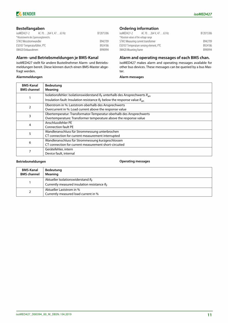
Ordering informationisoMED427-2 AC 70…264 V, 47…63 Hz B72075306*Absolute values of the voltage rangeSTW2 Measuring current transformer B942709ES0107 Temperature sensing element, PTC B924186XM420 Mounting frame B990994
Alarm and operating messages of each BMS chan.isoMED427 makes alarm and operating messages available forother bus devices. These messages can be queried by a bus Mas-ter.
Alarm messages
Operating messages
des Ansprechwerts Ran response value Ran
wertse valuealb des Ansprechwerts the response value
nd
ssenuited
BestellangabenisoMED427-2 AC 70…264 V, 47…63 Hz B72075306*Absolutwerte des SpannungsbereichsSTW2 Messstromwandler B942709ES0107 Temperaturfühler, PTC B924186XM420 Einbaurahmen B990994
Alarm- und Betriebsmeldungen je BMS-KanalisoMED427 stellt für andere Busteilnehmer Alarm- und Betriebs-meldungen bereit. Diese können durch einen BMS-Master abge-fragt werden.
Alarmmeldungen
Betriebsmeldungen
BMS-Kanal BMS channel
BedeutungMeaning
1Isolationsfehler: Isolationswiderstand RF unterhInsulation fault: Insulation resistance RF below t
2Überstrom in %: Laststrom oberhalb des AnspreOvercurrent in %: Load current above the respo
3Übertemperatur: Transformator-Temperatur obOvertemperature: Transformer temperature ab
4Anschlussfehler PEConnection fault PE
5Wandleranschluss für Strommessung unterbrocCT connection for current measurement interru
6Wandleranschluss für Strommessung kurzgeschCT connection for current measurement short-
7Gerätefehler, internDevice fault, internal
BMS-Kanal BMS channel
BedeutungMeaning
1Aktueller Isolationswiderstand RFCurrently measured insulation resistance RF
2Aktueller Laststrom in %Currently measured load current in %
11

Alle Rechte vorbehalten.Nachdruck und Vervielfältigungnur mit Genehmigung des Herausgebers.
Bender GmbH & Co. KGPostfach 1161 • 35301 Grünberg • DeutschlandLondorfer Str. 65 • 35305 Grünberg • DeutschlandTel.: +49 6401 807-0 • Fax: +49 6401 807-259E-Mail: [email protected] • www.bender.de
All rights reserved.Reprinting and duplicating
only with permission of the publisher.
Bender GmbH & Co. KGPO Box 1161 • 35301 Gruenberg • Germany
Londorfer Str. 65 • 35305 Gruenberg • GermanyTel.: +49 6401 807-0 • Fax: +49 6401 807-259
E-Mail: [email protected] • www.bender.de