Embed Size (px)
Citation preview
Handbuch/ManualDE EN
RCM470DDDeutsch English
RichtungsselektivesDifferenzstrom-Überwachungsgerätfür IT-Wechselspannungs-Systeme(AC und pulsierende DC-Ströme)
Bestimmungsgemäße VerwendungDas richtungsselektive Differenzstrom-ÜberwachungsgerätRCM470DD überwacht den Differenzstrom (AC, DC pulsierend) inungeerdeten AC- oder 3(N)AC-Systemen (IT-Systemen). Es ver-gleicht die Phasenlage des Messstromwandler-Signals (IΔ) mitdem Sternpunktsignal. Der Sternpunkt wird im RCM470DD gebil-det.Die Auswertung des Differenzstromes erfolgt richtungsselektiv,d. h. es werden nur Differenzströme gemeldet, deren Ursache aufder Verbraucherseite liegen. Damit kann in verzweigten IT-Syste-men eine selektive Ermittlung des Fehlerortes vorgenommenwerden.Voraussetzung für den Einsatz des Gerätes ist, dass vor demMessstromwandler eine ausreichend hohe Netzableitkapazi-tät vorhanden ist, damit ein Differenzstrom größer als der An-sprechwert fließen kann. In vielen Bereichen ist ein hoherAbleitstrom unerwünscht, so dass beim Einsatz von richtungsse-lektiven Differenzstrom-Überwachungsgeräten die Höhe des zu-lässigen Ableitstroms des IT-Systems bzw. das Einsatzgebietbeachtet werden muss. Da für das Messverfahren die Sternpunkt-spannung des überwachten IT-Systems notwendig ist, muss auchdie Nennspannung bei der Auswahl der Geräte berücksichtigtwerden.Für die Serie RCM470DD können externe Messstromwandler TypW… oder WR… eingesetzt werden. Für die Erweiterung desNennspannungsbereiches bis max. AC 1000 V (Absolutwert)steht das Ankoppelgerät CD470 zur Verfügung.
Gerätemerkmale● Externer Messstromwandler W…, WR…
● Ansprechwert einstellbar 10 mA…10 A
● Ansprechverzögerung einstellbar 0…10 s
● Alarmrelais mit 2 potentialfreien Wechslern
● Arbeits-/Ruhestrom wählbar
● Fehlerspeicherung wählbar
● Test- und Reset-Taste intern/extern
● LEDs für Betrieb und Alarm
● Anschlussüberwachung externer Messstromwandler
● Plombierbare Klarsichtabdeckung
● Gehäuse für Hutschienen- und Schraubmontage
● Separate Versorgungsspannung
● Ansprechcharakteristik nach IEC 62020
Das Gerät ist nicht geeignet für IT-Systeme mitUmrichtern oder Phasenabschnittsteuerungen.
RCM470DD_D00229_02_M_DEEN/04.2017
Directionally discriminatingresidual current monitor
for IT AC systems(AC and pulsed DC currents)
Intended useThe directionally discriminating residual current monitorRCM470DD monitors the residual current (AC, DC pulsed) in un-earthed AC or 3(N)AC systems (IT systems). It compares thephase position of the measuring current transformer signal (IΔ) tothe neutral point signal. The neutral point is situated in theRCM470DD.The evaluation of the residual current is performed in a direc-tionally discriminating way, i.e. only insulation faults on theload side are reported. This enables selective determination ofthe fault location in extended IT systems.A prerequisite for the application of the device is that a suffi-ciently high leakage capacitance is available upstream themeasuring current transformer so that a residual current high-er than the response value can flow. In many areas a high leakagecapacitance is undesirable, which means that the level of the per-missible leakage capacitance of the IT system or the area of appli-cation must be taken into account when using the directionallydiscriminating residual current monitor. Since the neutral pointvoltage of the IT system being monitored is required for themeasurement procedure, the nominal voltage must also be con-sidered when selecting the devices.External measuring current transformers of type W… or WR…can be used for the RCM470DD series. The coupling deviceCD470 is available for expansion of the nominal voltage range upto max. AC 1000 V (absolute value).
Device features● External measuring current transformer W…, WR…
● Response value selectable 10 mA…10 A
● Response delay selectable 0…10 s
● Alarm relay with two potential-free changeover contacts
● N/O or N/C operation selectable
● Fault memory selectable
● Test and reset button internal/external
● LEDs for operation and alarm
● Connection monitoring external measuring current trans-former
● Sealable transparent cover
● Enclosure for DIN rail and screw mounting
● Separate supply voltage
● Operating characteristics acc. to IEC 62020
The device is not suitable for IT systems with in-verters or trailing-edge phase controls.
1
RCM470DD
fes
Sicherheitshinweise Bestandteil der Gerätedokumentation sind neben diesem Hand-buch die beiliegenden „Sicherheitshinweise für Bender-Produkte“.
Montage und Anschluss
Montage auf HutschieneRasten Sie die rückseitigen Klemmfedern des Geräts auf der Hut-schiene so ein, dass ein sicherer und fester Sitz gewährleistet ist.Alternativ ist eine Schraubbefestigung möglich.
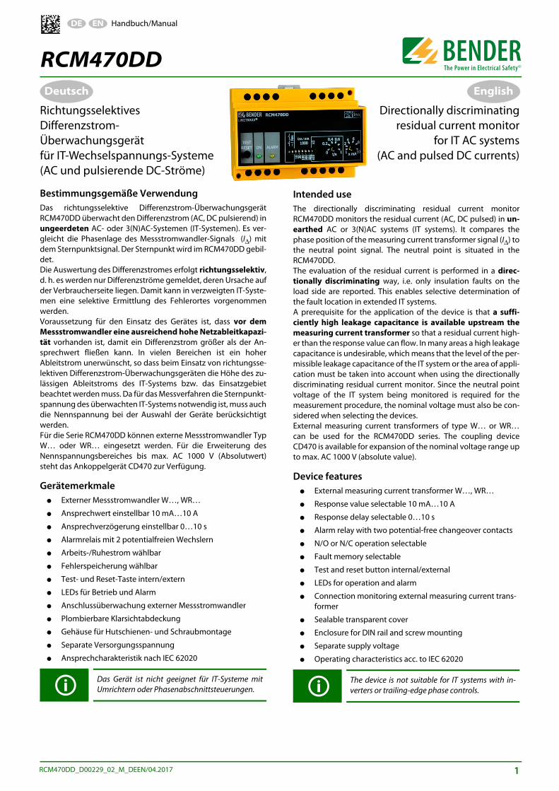
Maßbild
Abb. 1: Maßbild RCM470DD/CD470
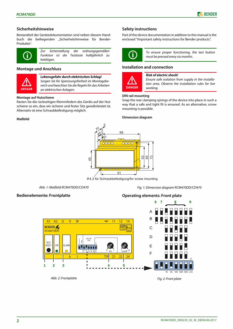
Bedienelemente: Frontplatte
Abb. 2: Frontplatte
Zur Sicherstellung der ordnungsgemäßenFunktion ist die Testtaste halbjährlich zubetätigen.
Lebensgefahr durch elektrischen Schlag!Sorgen Sie für Spannungsfreiheit im Montagebe-reich und beachten Sie die Regeln für das Arbeitenan elektrischen Anlagen.GEFAHR
für Schraubbe
RCM470DD
1 2 3 4
2
tigung/for screw mounting}6
5
7 8 9
A
B
C
D
E
F
Safety instructions Part of the device documentation in addition to this manual is theenclosed "Important safety instructions for Bender products".
Installation and connection
DIN rail mountingSnap the rear clamping springs of the device into place in such away that a safe and tight fit is ensured. As an alternative, screwmounting is possible.
Dimension diagram
Fig. 1: Dimension diagram RCM470DD/CD470
Operating elements: Front plate
Fig. 2: Front plate
To ensure proper functioning, the test buttonmust be pressed every six months.
Risk of electric shock!Ensure safe isolation from supply in the installa-tion area. Observe the installation rules for liveworking.DANGER
RCM470DD_D00229_02_M_DEEN/04.2017
RCM470DD_D00229_02_M_DEEN/04.2017
RCM470DD
1
2
3
4
5
6
7
8
9
Key
Note 1)
DIP switch (key 6…9)White = switch position
Changes to the DIP switches may only be carried out when the power supply is disconnected!
Combined test and reset button "TEST/RESET";short-time pressing (< 1 s) = RESET,long-time pressing (> 2 s) = TEST.
Operation LED "ON"
Alarm LED "ALARM": is lit: fault current exceeds response value flashes: measuring current transformer connection inter-rupted.
Potentiometer for setting the response delay (0…1 s).
Potentiometer for setting the response value (x 1…10) mA
Setting of the operating mode of the alarm relay 1)
A N/O operationB N/C operation
Fault memory relay + LED 1)
A fault memory ONB fault memory OFF
Setting of the response range (x 1…10) 1)
A 10 mAB 30 mAC 100 mA D 300 mAE 500 mA F 1000 mA
Setting of the response delay 1)
A x 1B x 10
Legende
Anmerkung 1)
Kombinierte Test- und Reset-Taste „TEST/RESET“;kurzzeitiges Drücken (< 1 s) = RESET,längeres Drücken (> 2 s) = TEST.
Betriebs-LED „ON“
Alarm-LED „ALARM“: leuchtet: Fehlerstrom überschreitet Ansprechwert blinkt: Messstromwandlerverbindung unterbrochen.
Potentiometer zum Einstellen der Ansprechverzögerung (0…1 s).
Potentiometer zum Einstellen des Ansprechwertes (x 1…10 mA)
Einstellung der Arbeitsweise des Alarmrelais 1)
A ArbeitsstromschaltungB Ruhestromschaltung
Fehlerspeicherung Relais + LED 1)
A Fehlerspeicherung ONB Fehlerspeicherung OFF
Einstellung des Ansprechbereiches (x 1…10) 1)
A 10 mAB 30 mAC 100 mA D 300 mAE 500 mA F 1000 mA
Einstellung der Ansprechverzögerung 1)
A x 1B x 10
DIP-Schalter (Legende 6…9)Weiß = Schalterstellung
Nehmen Sie eine Umschaltung der DIP-Schalter nur im spannungslosen Zustand vor!
3
4
RCM470DD
1
2
3
4
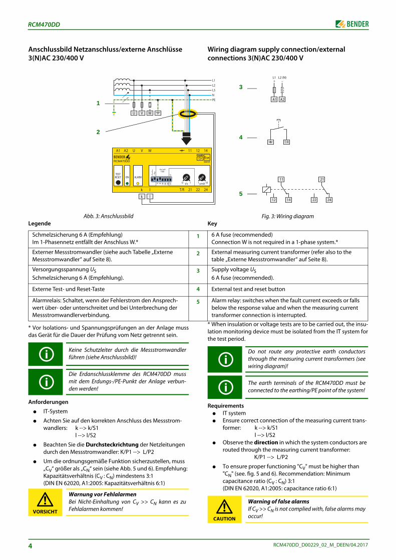
5
Wiring diagram supply connection/external connections 3(N)AC 230/400 V
Fig. 3: Wiring diagramKey
* When insulation or voltage tests are to be carried out, the insu-lation monitoring device must be isolated from the IT system forthe test period.
Requirements● IT system● Ensure correct connection of the measuring current trans-
former: k --> k/S1l --> l/S2
● Observe the direction in which the system conductors are routed through the measuring current transformer:
K/P1 --> L/P2
● To ensure proper functioning "CV" must be higher than "CN" (see. fig. 5 and 6). Recommendation: Minimum capacitance ratio (CV : CN) 3:1 (DIN EN 62020, A1:2005: capacitance ratio 6:1)
Do not route any protective earth conductorsthrough the measuring current transformers (seewiring diagram)!
The earth terminals of the RCM470DD must beconnected to the earthing/PE point of the system!
Warning of false alarmsIf CV >> CN is not complied with, false alarms mayoccur! CAUTION
6 A fuse (recommended) Connection W is not required in a 1-phase system.*
External measuring current transformer (refer also to the table „Externe Messstromwandler“ auf Seite 8).
Supply voltage US 6 A fuse (recommended).
External test and reset button
Alarm relay: switches when the fault current exceeds or falls below the response value and when the measuring current transformer connection is interrupted.
3
4
5
Anschlussbild Netzanschluss/externe Anschlüsse 3(N)AC 230/400 V
Abb. 3: AnschlussbildLegende
* Vor Isolations- und Spannungsprüfungen an der Anlage mussdas Gerät für die Dauer der Prüfung vom Netz getrennt sein.
Anforderungen
● IT-System
● Achten Sie auf den korrekten Anschluss des Messstrom-wandlers: k --> k/S1
l --> l/S2
● Beachten Sie die Durchsteckrichtung der Netzleitungen durch den Messstromwandler: K/P1 --> L/P2
● Um die ordnungsgemäße Funktion sicherzustellen, muss „CV“ größer als „CN“ sein (siehe Abb. 5 und 6). Empfehlung: Kapazitätsverhältnis (CV : CN) mindestens 3:1 (DIN EN 62020, A1:2005: Kapazitätsverhältnis 6:1)
Schmelzsicherung 6 A (Empfehlung) Im 1-Phasennetz entfällt der Anschluss W.*
Externer Messstromwandler (siehe auch Tabelle „Externe Messstromwandler“ auf Seite 8).
Versorgungsspannung US Schmelzsicherung 6 A (Empfehlung).
Externe Test- und Reset-Taste
Alarmrelais: Schaltet, wenn der Fehlerstrom den Ansprech-wert über- oder unterschreitet und bei Unterbrechung der Messstromwandlerverbindung.
Keine Schutzleiter durch die Messstromwandlerführen (siehe Anschlussbild)!
Die Erdanschlussklemme des RCM470DD mussmit dem Erdungs-/PE-Punkt der Anlage verbun-den werden!
Warnung vor FehlalarmenBei Nicht-Einhaltung von CV >> CN kann es zuFehlalarmen kommen!
RCM470DD
1
2
VORSICHT
RCM470DD_D00229_02_M_DEEN/04.2017
RCM470DD_D00229_02_M_DEEN/04.2017
RCM470DD
(N)
RC
N
U
C
U
R
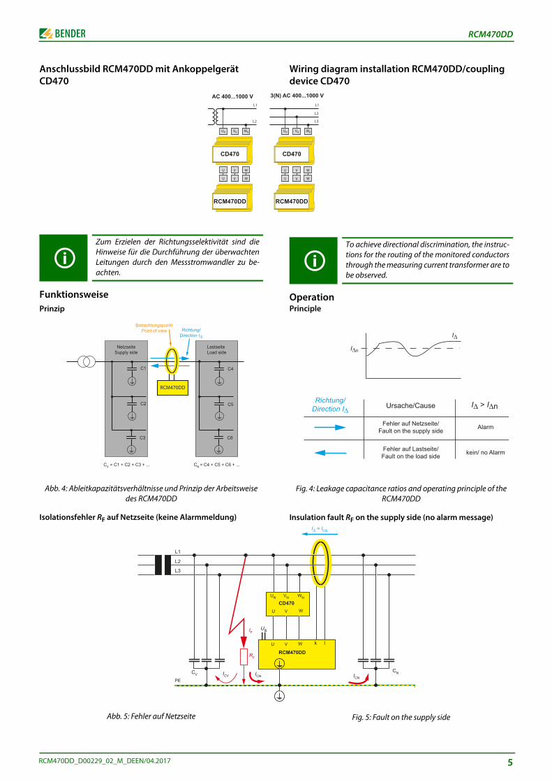
Wiring diagram installation RCM470DD/coupling device CD470
OperationPrinciple
Fig. 4: Leakage capacitance ratios and operating principle of the RCM470DD
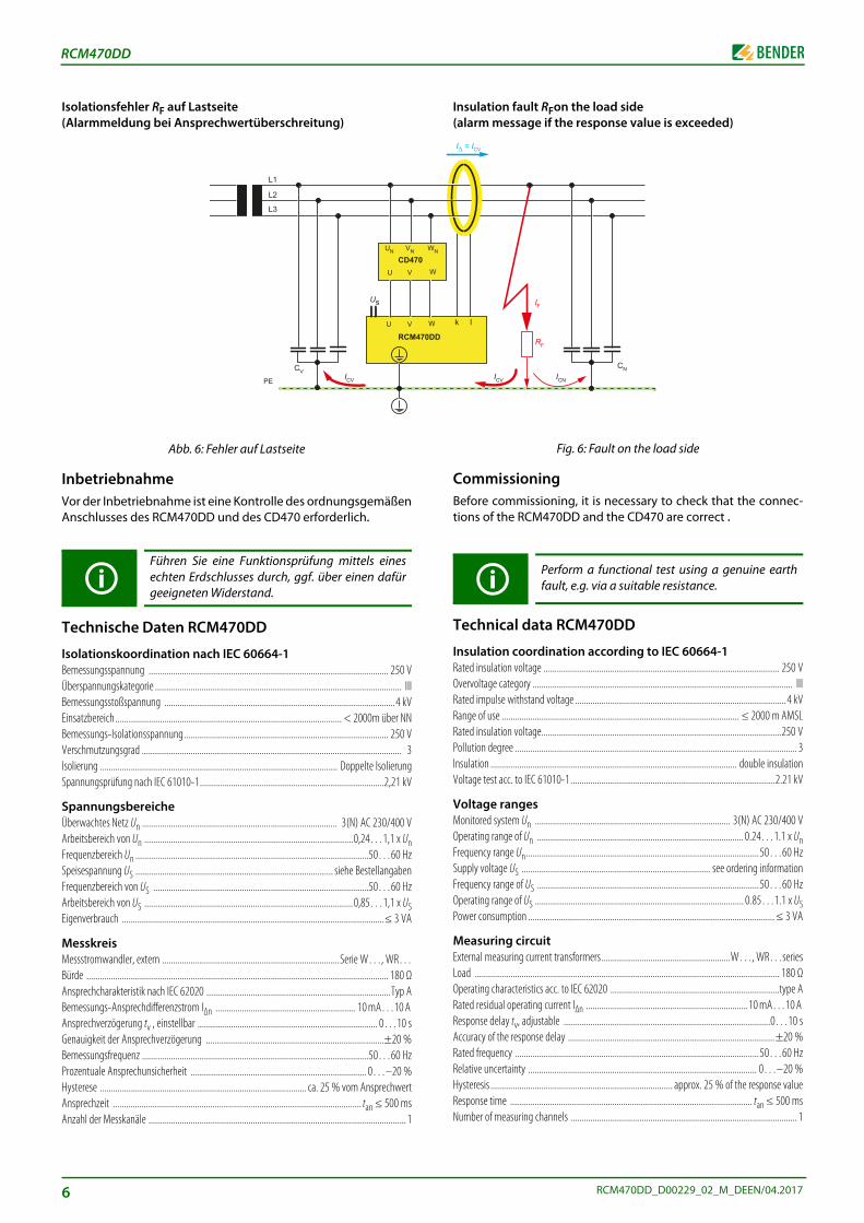
Insulation fault RF on the supply side (no alarm message)
Fig. 5: Fault on the supply side
To achieve directional discrimination, the instruc-tions for the routing of the monitored conductorsthrough the measuring current transformer are tobe observed.
AC 400...1000 V
CD470
M470DD
IΔ > IΔn
Alarm
kein/ no Alarm
IΔn
IΔ
Richtung/Direction IΔ
Fehler auf Lastseite/Fault on the load side
Fehler auf Netzseite/Fault on the supply side
Ursache/Cause
VN WN
V WD470
V W k l
CM470DD
ICN
CN
IΔ = ICN
Anschlussbild RCM470DD mit Ankoppelgerät CD470
FunktionsweisePrinzip
Abb. 4: Ableitkapazitätsverhältnisse und Prinzip der Arbeitsweise des RCM470DD
Isolationsfehler RF auf Netzseite (keine Alarmmeldung)
Abb. 5: Fehler auf Netzseite
Zum Erzielen der Richtungsselektivität sind dieHinweise für die Durchführung der überwachtenLeitungen durch den Messstromwandler zu be-achten.
AC 400...1000 V 3
CD470
RCM470DD
C1
C2
C3
C4
C5
C6
CV = C1 + C2 + C3 + ... CN = C4 + C5 + C6 + ...
BetrachtungspunktPoint of view Richtung/
Direction IΔ
RCM470DD
NetzseiteSupply side
LastseiteLoad side
U
Us
L1
L2
L3
CV
IF
RF
ICV ICNPE
5
6
RCM470DD
WN
W
W
0DD
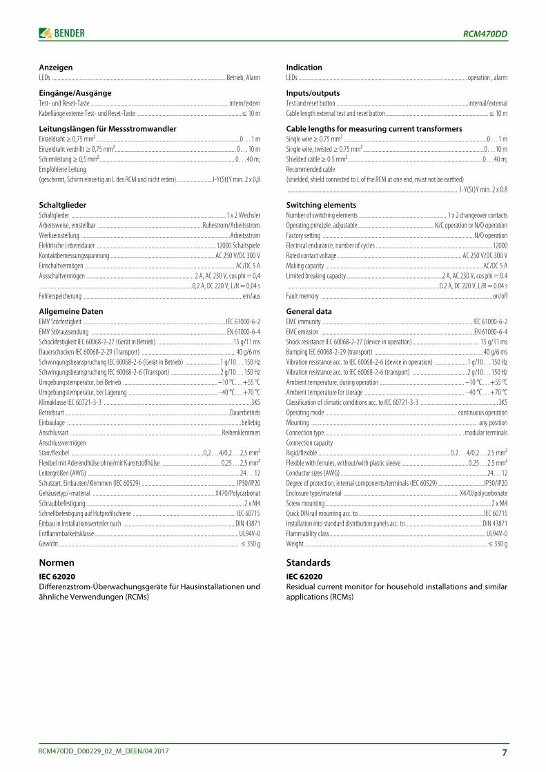
Insulation fault RFon the load side (alarm message if the response value is exceeded)
Fig. 6: Fault on the load side
CommissioningBefore commissioning, it is necessary to check that the connec-tions of the RCM470DD and the CD470 are correct .
Technical data RCM470DD
Insulation coordination according to IEC 60664-1Rated insulation voltage .......................................................................................................... 250 VOvervoltage category ..................................................................................................................... IIIRated impulse withstand voltage ............................................................................................... 4 kVRange of use ........................................................................................................... ≤ 2000 m AMSLRated insulation voltage............................................................................................................250 VPollution degree ............................................................................................................................... 3Insulation ............................................................................................................... double insulationVoltage test acc. to IEC 61010-1............................................................................................2.21 kV
Voltage rangesMonitored system Un ........................................................................................ 3(N) AC 230/400 VOperating range of Un ............................................................................................. 0.24…1.1 x UnFrequency range Un.........................................................................................................50…60 HzSupply voltage US ..................................................................................... see ordering informationFrequency range of US ....................................................................................................50…60 HzOperating range of US .............................................................................................. 0.85…1.1 x USPower consumption ............................................................................................................... ≤ 3 VA
Measuring circuitExternal measuring current transformers..........................................................W…, WR…seriesLoad ......................................................................................................................................... 180 ΩOperating characteristics acc. to IEC 62020 ............................................................................type ARated residual operating current IΔn .........................................................................10 mA…10 A Response delay tv, adjustable .............................................................................................0…10 sAccuracy of the response delay .............................................................................................±20 %Rated frequency ..............................................................................................................50…60 HzRelative uncertainty ....................................................................................................... 0…–20 %Hysteresis .................................................................................. approx. 25 % of the response valueResponse time ............................................................................................................. tan ≤ 500 msNumber of measuring channels ...................................................................................................... 1
Perform a functional test using a genuine earthfault, e.g. via a suitable resistance.
k l
ICN
CN
IΔ = ICV
IF
RF
ICV
Isolationsfehler RF auf Lastseite (Alarmmeldung bei Ansprechwertüberschreitung)
Abb. 6: Fehler auf Lastseite
InbetriebnahmeVor der Inbetriebnahme ist eine Kontrolle des ordnungsgemäßenAnschlusses des RCM470DD und des CD470 erforderlich.
Technische Daten RCM470DD
Isolationskoordination nach IEC 60664-1Bemessungsspannung ............................................................................................................ 250 VÜberspannungskategorie ............................................................................................................... IIIBemessungsstoßspannung ........................................................................................................4 kVEinsatzbereich ...................................................................................................... < 2000m über NNBemessungs-Isolationsspannung ............................................................................................ 250 VVerschmutzungsgrad ..................................................................................................................... 3Isolierung ........................................................................................................... Doppelte IsolierungSpannungsprüfung nach IEC 61010-1...................................................................................2,21 kV
SpannungsbereicheÜberwachtes Netz Un ........................................................................................ 3(N) AC 230/400 VArbeitsbereich von Un ..............................................................................................0,24…1,1 x UnFrequenzbereich Un .........................................................................................................50…60 HzSpeisespannung US ......................................................................................... siehe BestellangabenFrequenzbereich von US .................................................................................................50…60 HzArbeitsbereich von US ..............................................................................................0,85…1,1 x USEigenverbrauch ......................................................................................................................≤ 3 VA
MesskreisMessstromwandler, extern ................................................................................Serie W…, WR…Bürde ........................................................................................................................................ 180 ΩAnsprechcharakteristik nach IEC 62020 ...................................................................................Typ ABemessungs-Ansprechdifferenzstrom IΔn ............................................................... 10 mA…10 A Ansprechverzögerung tv , einstellbar ................................................................................. 0…10 sGenauigkeit der Ansprechverzögerung ................................................................................±20 %Bemessungsfrequenz ......................................................................................................50…60 HzProzentuale Ansprechunsicherheit ............................................................................... 0…–20 %Hysterese ............................................................................................. ca. 25 % vom AnsprechwertAnsprechzeit ................................................................................................................ tan ≤ 500 msAnzahl der Messkanäle ....................................................................................................................1
Führen Sie eine Funktionsprüfung mittels einesechten Erdschlusses durch, ggf. über einen dafürgeeigneten Widerstand.
UN VN
U V
CD470
U V
Us
RCM47
L1
L2
L3
CV
PE ICV
RCM470DD_D00229_02_M_DEEN/04.2017
RCM470DD
AnzeigenLEDs ............................................................................................................................ Betrieb, Alarm
Eingänge/AusgängeTest- und Reset-Taste .................................................................................................. intern/externKabellänge externe Test- und Reset-Taste .......................................................................... ≤ 10 m
Leitungslängen für MessstromwandlerEinzeldraht ≥ 0,75 mm² ......................................................................................................0…1 mEinzeldraht verdrillt ≥ 0,75 mm²...................................................................................... 0…10 mSchirmleitung ≥ 0,5 mm²................................................................................................ 0…40 m;Empfohlene Leitung(geschirmt, Schirm einseitig an L des RCM und nicht erden).........................J-Y(St)Y min. 2 x 0,8
SchaltgliederSchaltglieder ..............................................................................................................1 x 2 WechslerArbeitsweise, einstellbar ..........................................................................Ruhestrom/ArbeitsstromWerkseinstellung ..........................................................................................................ArbeitsstromElektrische Lebensdauer .....................................................................................12000 SchaltspieleKontaktbemessungsspannung .......................................................................... AC 250 V/DC 300 VEinschaltvermögen ...........................................................................................................AC/DC 5 AAusschaltvermögen ............................................................................ 2 A, AC 230 V, cos phi = 0,4.............................................................................................................0,2 A, DC 220 V, L/R = 0,04 sFehlerspeicherung .................................................................................................................ein/aus
Allgemeine DatenEMV Störfestigkeit ..................................................................................................... IEC 61000-6-2EMV Störaussendung ................................................................................................ EN 61000-6-4Schockfestigkeit IEC 60068-2-27 (Gerät in Betrieb) .....................................................15 g/11 msDauerschocken IEC 60068-2-29 (Transport) ................................................................... 40 g/6 msSchwingungsbeanspruchung IEC 60068-2-6 (Gerät in Betrieb) .........................1 g/10…150 HzSchwingungsbeanspruchung IEC 60068-2-6 (Transport) ...................................2 g/10…150 HzUmgebungstemperatur, bei Betrieb ...................................................................–10 °C…+55 °CUmgebungstemperatur, bei Lagerung ............................................................... –40 °C…+70 °CKlimaklasse IEC 60721-3-3 .........................................................................................................3K5Betriebsart .....................................................................................................................DauerbetriebEinbaulage ............................................................................................................................beliebigAnschlussart ............................................................................................................ReihenklemmenAnschlussvermögenStarr/flexibel ..............................................................................................0,2…4/0,2…2,5 mm²Flexibel mit Aderendhülse ohne/mit Kunststoffhülse .......................................... 0,25…2,5 mm²Leitergrößen (AWG) ............................................................................................................24…12Schutzart, Einbauten/Klemmen (IEC 60529) ................................................................... IP30/IP20Gehäusetyp/-material ....................................................................................... X470/PolycarbonatSchraubbefestigung ................................................................................................................2 x M4Schnellbefestigung auf Hutprofilschiene ......................................................................... IEC 60715Einbau in Installationsverteiler nach ................................................................................DIN 43871Entflammbarkeitsklasse ...................................................................................................... UL94V-0Gewicht ................................................................................................................................ ≤ 350 g
NormenIEC 62020Differenzstrom-Überwachungsgeräte für Hausinstallationen undähnliche Verwendungen (RCMs)
RCM470DD_D00229_02_M_DEEN/04.2017
IndicationLEDs ........................................................................................................................ operation , alarm
Inputs/outputsTest and reset button ..............................................................................................internal/externalCable length external test and reset button ......................................................................... ≤ 10 m
Cable lengths for measuring current transformersSingle wire ≥ 0.75 mm² ......................................................................................................0…1 mSingle wire, twisted ≥ 0.75 mm²......................................................................................0…10 mShielded cable ≥ 0.5 mm²................................................................................................0…40 m;Recommended cable(shielded, shield connected to L of the RCM at one end, must not be earthed)......................................................................................................................... J-Y(St)Y min. 2 x 0.8
Switching elementsNumber of switching elements .............................................................. 1 x 2 changeover contactsOperating principle, adjustable...................................................... N/C operation or N/O operationFactory setting ............................................................................................................N/O operationElectrical endurance, number of cycles ...................................................................................12000Rated contact voltage ........................................................................................ AC 250 V/DC 300 VMaking capacity ................................................................................................................ AC/DC 5 ALimited breaking capacity ....................................................................2 A, AC 230 V, cos phi = 0.4............................................................................................................0.2 A, DC 220 V, L/R = 0.04 sFault memory .......................................................................................................................... on/off
General dataEMC immunity ........................................................................................................... IEC 61000-6-2EMC emission .............................................................................................................EN 61000-6-4Shock resistance IEC 60068-2-27 (device in operation)............................................... 15 g/11 msBumping IEC 60068-2-29 (transport) ............................................................................. 40 g/6 msVibration resistance acc. to IEC 60068-2-6 (device in operation) .......................1 g/10…150 HzVibration resistance acc. to IEC 60068-2-6 (transport) .......................................2 g/10…150 HzAmbient temperature, during operation ............................................................ –10 °C…+55 °CAmbient temperature for storage ....................................................................... –40 °C…+70 °CClassification of climatic conditions acc. to IEC 60721-3-3 .......................................................3K5Operating mode ............................................................................................. continuous operationMounting ...................................................................................................................... any positionConnection type....................................................................................................modular terminalsConnection capacityRigid/flexible ..............................................................................................0.2…4/0.2…2.5 mm²Flexible with ferrules, without/with plastic sleeve ................................................0.25…2.5 mm²Conductor sizes (AWG) ........................................................................................................24…12Degree of protection, internal components/terminals (IEC 60529)................................. IP30/IP20Enclosure type/material .................................................................................. X470/polycarbonateScrew mounting ...................................................................................................................... 2 x M4Quick DIN rail mounting acc. to .........................................................................................IEC 60715Installation into standard distribution panels acc. to.......................................................DIN 43871Flammability class............................................................................................................... UL94V-0Weight .................................................................................................................................. ≤ 350 g
StandardsIEC 62020Residual current monitor for household installations and similarapplications (RCMs)
7
RCM470DD
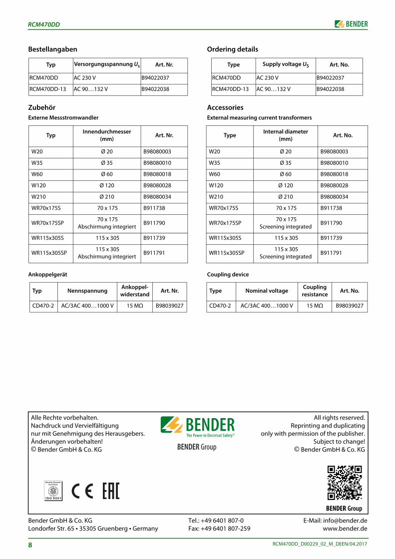
Bestellangaben
ZubehörExterne Messstromwandler
Ankoppelgerät
Typ Versorgungsspannung Us Art. Nr.
RCM470DD AC 230 V B94022037
RCM470DD-13 AC 90…132 V B94022038
TypInnendurchmesser
(mm)Art. Nr.
W20 Ø 20 B98080003
W35 Ø 35 B98080010
W60 Ø 60 B98080018
W120 Ø 120 B98080028
W210 Ø 210 B98080034
WR70x175S 70 x 175 B911738
WR70x175SP 70 x 175
Abschirmung integriertB911790
WR115x305S 115 x 305 B911739
WR115x305SP 115 x 305
Abschirmung integriertB911791
Typ NennspannungAnkoppel-widerstand
Art. Nr.
CD470-2 AC/3AC 400…1000 V 15 MΩ B98039027
8
Bender GmbH & Co. KG Tel.: +Londorfer Str. 65 • 35305 Gruenberg • Germany Fax: +
Alle Rechte vorbehalten. Nachdruck und Vervielfältigung nur mit Genehmigung des Herausgebers.Änderungen vorbehalten!© Bender GmbH & Co. KG
Ordering details
AccessoriesExternal measuring current transformers
Coupling device
Type Supply voltage US Art. No.
RCM470DD AC 230 V B94022037
RCM470DD-13 AC 90…132 V B94022038
TypeInternal diameter
(mm)Art. No.
W20 Ø 20 B98080003
W35 Ø 35 B98080010
W60 Ø 60 B98080018
W120 Ø 120 B98080028
W210 Ø 210 B98080034
WR70x175S 70 x 175 B911738
WR70x175SP 70 x 175
Screening integratedB911790
WR115x305S 115 x 305 B911739
WR115x305SP 115 x 305
Screening integratedB911791
Type Nominal voltageCoupling resistance
Art. No.
CD470-2 AC/3AC 400…1000 V 15 MΩ B98039027
RCM470DD_D00229_02_M_DEEN/04.2017
49 6401 807-0 E-Mail: [email protected] 6401 807-259 www.bender.de
All rights reserved.Reprinting and duplicating
only with permission of the publisher.Subject to change!
© Bender GmbH & Co. KG
BENDER Group