Embed Size (px)
Citation preview
1 / 16
MA000 (de_en)Montageanleitung
MA000 (de_en)Assembly instructions
MA082 (de_en)Montageanleitung
MA082 (de_en)Assembly instructions
Steckverbinder MPC-S
Connectors MPC-S
InhaltLieferstatus der Komponenten ��������������������������������������������������1 Sicherheitshinweise��������������������������������������������������������������������2Empfohlenes Werkzeug ������������������������������������������������������������3Vorbereitung der Leitung �����������������������������������������������������������6Crimpen �������������������������������������������������������������������������������������7Vorbereitung des Steckverbinderkörpers ����������������������������������8Kodierung ����������������������������������������������������������������������������������8Kennzeichnung ��������������������������������������������������������������������������9Zusammenbau der Kontakte im Steckverbinder ���������������������10Festziehen der Kabelverschraubung ����������������������������������������13Verwendung des Steckverbinders �������������������������������������������13Verbinden und Trennen des Steckverbinders ��������������������������14Zubehör �����������������������������������������������������������������������������������14Notizen ������������������������������������������������������������������������������������16
ContentDelivery status of components ��������������������������������������������������2Safety Instructions ����������������������������������������������������������������������3Suggested tools �������������������������������������������������������������������������4Cable preparation ����������������������������������������������������������������������6Crimping ������������������������������������������������������������������������������������7Preparation of the body configuration ���������������������������������������8Coding ���������������������������������������������������������������������������������������8Marking �������������������������������������������������������������������������������������9Assembling the contacts into the body of the connector �������10Tightening of the cable gland ��������������������������������������������������13Using the connector ����������������������������������������������������������������13Connecting and disconnecting the connector ������������������������14Accessories �����������������������������������������������������������������������������14Notes ���������������������������������������������������������������������������������������16
2 / 16
1
2 3
4
5
6
Lieferstatus der Komponenten Delivery status of components
1. Steckverbinderkörper für Stecker oder Buchse2. Crimpkontakte3. Halteringe4. Kodierstifte5. Kennzeichnungsstifte6. Kabelverschraubung-Einsätze
1. Body configuration male or female2. Crimping contacts3. Retaining rings f4. Coding pins5. Marking pins6. Cable gland inserts
3 / 16
Sicherheitshinweise Safety instructions
Die Montage und Installation der Produkte darf ausschließlich durch Elektrofachkräfte oder elektrotechnisch unterwiesene Per-sonen unter Berücksichtigung aller anwendbaren gesetzlichen Sicherheitsbestimmungen und Regelungen erfolgen.Stäubli Electrical Connectors (Stäubli) lehnt jegliche Haftung infol-ge Nichteinhaltung dieser Warnhinweise ab.
The products may be assembled and installed by electrically skilled or instructed persons duly observing all applicable safety regulations.Stäubli Electrical Connectors (Stäubli) does not accept any liabil-ity in the event of failure to observe these warnings.
Benutzen Sie nur die von Stäubli angegebenen Einzelteile und Werkzeuge. Weichen Sie nicht von den hier beschriebenen Vorgängen zur Vorbereitung und Montage ab, da sonst bei der Selbstkonfektionierung weder die Sicherheit noch die Einhaltung der technischen Daten gewährleistet ist. Ändern Sie das Produkt in keiner Weise ab.
Use only the components and tools specified by Stäubli. In case of self-assembly, do not deviate from the preparation and assem-bly instructions as stated herein, otherwise Stäubli cannot give any guarantee as to safety or conformity with the technical data. Do not modify the product in any way.
Nicht von Stäubli hergestellte Steckverbindungen, die mit Stäubli-Elementen steckbar sind und von einigen Herstellern manchmal auch als „Stäubli-kompatibel“ bezeichnet werden, entsprechen nicht den Anforderungen für eine sichere, langzeitstabile elekt-rische Verbindung und dürfen aus Sicherheitsgründen nicht mit Stäubli-Elementen gesteckt werden. Stäubli übernimmt daher keine Haftung, falls diese von Stäubli nicht freigegebenen Steck-verbindungen mit Stäubli-Elementen gesteckt werden und des-halb Schäden entstehen.
Connectors not originally manufactured by Stäubli which can be mated with Stäubli elements and in some cases are even de-scribed as ”Stäubli-compatible” by certain manufacturers do not conform to the requirements for safe electrical connection with long-term stability, and for safety reasons must not be plugged together with Stäubli elements. Stäubli therefore does not ac-cept any liability for any damages resulting from mating such connectors (i.e. lacking Stäubli approval) with Stäubli elements.
Caution, risk of electric shock (IEC 60417-6042)
Arbeiten im spannungsfreien ZustandDie fünf Sicherheitsregeln sind bei Arbeiten an elektrischen Instal-lationen zu beachten.Nachdem die betroffenen Anlagenteile festgelegt sind, müssen die folgenden fünf wesentlichen Anforderungen in der angege-benen Reihenfolge eingehalten werden, sofern es nicht wichtige Gründe gibt, davon abzuweichen: – Freischalten; – gegen Wiedereinschalten sichern; – Spannungsfreiheit feststellen; – Erden und kurzschließen; – benachbarte, unter Spannung stehende Teile abdecken oder
abschranken. Alle an der Arbeit beteiligten Personen müssen Elektrofachkräf-te oder elektrotechnisch unterwiesene Personen sein oder unter Aufsichtsführung einer solchen Person stehen.Quelle: EN 50110-1:2013 (DIN EN 50110-1, VDE 0105-1)
Work in a de-energized stateFollow the five safety rules, when working on electrical installa-tions.After the respective electrical installations have been identified, the following five essential requirements shall be undertaken in the specified order unless there are essential reasons for doing otherwise:- disconnect completely;- secure against re-connection;- verify absence of operating voltage;- carry out earthing and short-circuiting;- provide protection against adjacent live parts.Any person engaged in this work activity shall be electrically skilled or instructed, or shall be supervised by such a person.Source: EN 50110-1:2013
Der Schutz gegen elektrischen Schlag ist auch in den Endan-wendungen zu prüfen.
Protection against electric shock shall be checked in the end-use applications too.
Caution (ISO 7000-0434B)
Vor jedem Gebrauch ist visuell zu prüfen, ob keine äußeren Män-gel vorhanden sind (besonders an der Isolation). Wenn Zweifel bezüglich der Sicherheit bestehen, muss ein Fachmann hinzuge-zogen oder der Steckverbinder ausgetauscht werden.
Each time the connector is used, it should previously be inspected for external defects (particularly the insulation). If there are any doubts as to its safety, a specialist must be consulted or the connector must be replaced.
Die Steckverbinder sind wasserdicht gemäß der für das jeweilige Produkt angegebenen IP-Schutzart.
The plug connectors are watertight in accordance with the product specific IP protection class.
Nicht gesteckte Steckverbinder sind vor Feuchtigkeit und Schmutz zu schützen. Die Steckverbinder dürfen nicht in ver-schmutztem Zustand miteinander gesteckt werden.
Unmated plug connectors must be protected from moisture and dirt. The male and female parts must not be plugged together when soiled.
Nützlicher Hinweis oder Tipp Useful hint or tip
Weitere technische Daten entnehmen Sie bitte dem Produktka-talog.
For further technical data please see the product catalog.

4 / 16
1
Empfohlenes Werkzeug Suggested tools
Crimpung Crimping
SteckerMale
BuchseFemale
Kontaktquer-schnitt (mm2) Contact cross-section (mm2)
Hydraulische Crimpzange und Halterung
Hydraulic crimping tool and die holder
Einsatz Crimping
die
Flache Seite
Flat side mm
Breite Width mm
6-kant Crimpung Hex� crimp
Contact 19�2203
Contact 19�2303 10
MECATRACTION SU 210 K + S21 oder / or
MECATRACTION ESU 137 + U137C12
ELSV20
C12 ELS5,8 ± 0,15 7
Contact 19�2204 19�2212
Contact 19�2304 19�2312
16MECATRACTION SU 210 K + S21
oder / orMECATRACTION ESU 137 + U137C12
FLSV20
C12ELS56,8 ± 0,15 7
Contact 19�2205 19�2213
Contact 19�2205 19�2313
25MECATRACTION SU 210 K + S21
oder / orMECATRACTION ESU 137 + U137C12
TN25V20
C12TN258,1 ± 0,15 8
Contact 19�2206 19�2214
Contact 19�2306 19�2213
35MECATRACTION SU 210 K + S21
oder / orMECATRACTION ESU 137 + U137C12
TN35V20
C12TN359,3 ± 0,15 8
Contact 19�2207 19�2215
Contact 19�2307 19�2315
50MECATRACTION SU 210 K + S21
oder / orMECATRACTION ESU 137 + U137C12
TN50V20
C12TN5011± 0,15 12
Contact 19�2216 19�2222
Contact 19�2316 19�2322
70MECATRACTION SU 210 K + S21
oder / orMECATRACTION ESU 137 + U137C12
TN70V20
C12TN7012,6 ± 0,15 12
Contact 19�2217 19�2223
Contact 19�2317 19�2323
95MECATRACTION SU 210 K + S21
oder / orMECATRACTION ESU 137 + U137C12
TN95V20
C12TN9514,6 ± 0,15 13
Contact 19�2224 19�2230
Contact 19�2324 19�2330
120MECATRACTION SU 210 K + S21
oder / orMECATRACTION ESU 137 + U137C12
TN120V20
C12TN12016,4 ± 0,15 15
Contact 19�2225 19�2231
Contact 19�2325 19�2331
150MECATRACTION SU 210 K + S21
oder / orMECATRACTION ESU 137 + U137C12
TN150V20
C12TN15018,4 ± 0,15 15
Contact 19�2232
Contact 19�2332 185
MECATRACTION SU 210 K + S21oder / or
MECATRACTION ESU 137 + U137C12
TN185V20
C12TN18520,4 ± 0,15 16
Contact 19�2233
Contact 19�2333 240
MECATRACTION SU 210 K + S21oder / or
MECATRACTION ESU 137 + U137C12
TN240V20
C12TN24023 ± 0,15 10
Einsatz Crimping die
Einsatz Crimping die
MECATRACTION SU 210 K + Halterung / die holder S21
MECATRACTION ESU 137 + Halterung / die holder U137C12
Tab. 1

5 / 16
2
3
7
5
4
6A B C
(ill. 2)Haltering-Montagewerkzeug für Kon-takte Ø 8 mm Type: MPC-TO/S-XAC/CT-S8 Bestell-Nr� 19�2911
(ill. 2)Mounting tool for retaining ring for male contact Ø 8 mm Type: MPC-TO/S-XAC/CT-S8 Order No� 19�2911
Haltering-Montagewerkzeug für Kon-takt Ø 14 mm Type: MPC-TO/S-XAC/CT-S14 Bestell-Nr� 19�2912
Mounting tool for retaining ring for male contact Ø 14 mm Type: MPC-TO/S-XAC/CT-S14 Order No� 19�2912
Haltering-Montagewerkzeug für Kon-takt Ø 20 mm Type: MPC-TO/S-XAC/CT-S20 Bestell-Nr� 19�2913
Mounting tool for retaining ring for male contact Ø 20 mm Type: MPC-TO/S-XAC/CT-S20 Order No� 19�2913
(ill. 3)Haltering-Montagewerkzeug (z�B�: FACOM ref 467) Typ: MPC-TO/PL-OP Bestell-Nr� 19�2933
Für Halteringe 19�2620, 19�2622, 19�2624 der Buchsen 19�2302 bis 19�2334
(ill. 3)Opening pliers for retaining rings (example: FACOM ref 467)Type: MPC-TO/PL-OPOrder No� 19�2933
For retaining rings 19�2620, 19�2622, 19�2624 on sockets 19�2302 up to 19�2334
(ill. 4)Lange, gerade Verlängerung für Halte-ring Montagewerkzeug 19�2933,Typ: MPC-TO/LES-PL Bestell-Nr� 19�2935 (zu bestellen je 2x)
Zur Demontage der Halteringe von den Steckern 19�2202 bis 19�2233�
(ill. 4)Long extensions straight for opening pliers 19�2933,Type: MPC-TO/LES-PL Order No� 19�2935 (to order 2x)
To be used to dismount the retaining rings on plugs 19�2202 to 19�2233�
(ill. 5)Ausbauwerkzeug für Kodierstift, Kenn-zeichnungsstift und BlockerstiftTyp: MPC-TO/LP-CP-MPBestell-Nr�: 19�2930
(ill. 5)Dismounting tool for coding pin, marking pin and locking pinType: MPC-TO/LP-CP-MPOrder No� 19�2930
(ill. 6)Drehmomentschlüssel (nicht durch Stäubli geliefert) und Einsätze:A - MPC-TO/CGM-A/2, 19�2926 (M20)B - MPC-TO/CGM-B/2, 19�2927 (M32)C - MPC-TO/CGM-C/2, 19�2928 (M40)
(ill. 6)Torque wrench (not provided by Stäu-bli) and inserts:A - MPC-TO/CGM-A/2, 19�2926 (M20)B - MPC-TO/CGM-B/2, 19�2927 (M32)C - MPC-TO/CGM-C/2, 19�2928 (M40)
(ill. 7)Steckschlüssel 1/2” für Sechskants-chraube M8 (flache Seite auf 6 mm)Länge 140 mm Typ: MPC-TO/SCD-M8 Bestell-Nr�: 19�2940
(ill. 7)Socket screwdriver 1/2’’ for hexagonal M8 metric socket head screws (flat side on 6 mm)Length 140 mmType: MPC-TO/SCD-M8 Order No�: 19�2940
6 / 16
8
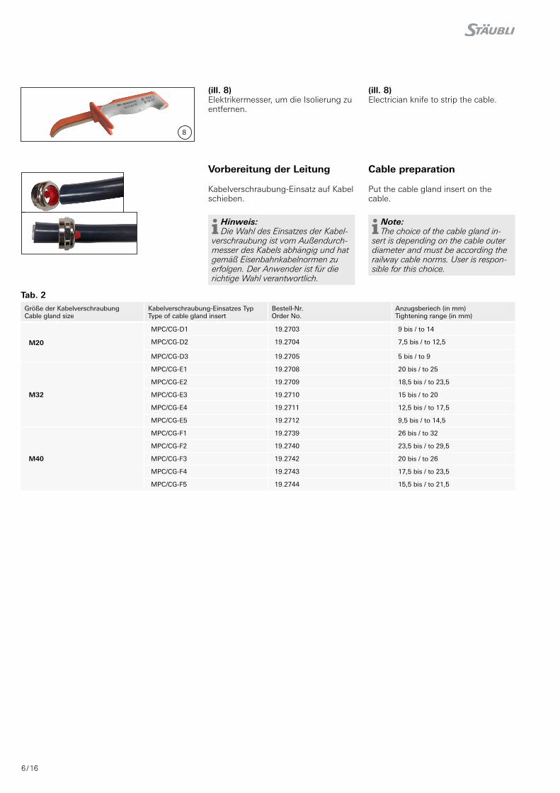
(ill. 8)Elektrikermesser, um die Isolierung zu entfernen�
(ill. 8)Electrician knife to strip the cable�
Größe der KabelverschraubungCable gland size
Kabelverschraubung-Einsatzes TypType of cable gland insert
Bestell-Nr.Order No.
Anzugsberiech (in mm)Tightening range (in mm)
M20
MPC/CG-D1 19.2703 9 bis / to 14
MPC/CG-D2 19.2704 7,5 bis / to 12,5
MPC/CG-D3 19.2705 5 bis / to 9
M32
MPC/CG-E1 19.2708 20 bis / to 25
MPC/CG-E2 19.2709 18,5 bis / to 23,5
MPC/CG-E3 19.2710 15 bis / to 20
MPC/CG-E4 19.2711 12,5 bis / to 17,5
MPC/CG-E5 19.2712 9,5 bis / to 14,5
M40
MPC/CG-F1 19.2739 26 bis / to 32
MPC/CG-F2 19.2740 23,5 bis / to 29,5
MPC/CG-F3 19.2742 20 bis / to 26
MPC/CG-F4 19.2743 17,5 bis / to 23,5
MPC/CG-F5 19.2744 15,5 bis / to 21,5
Tab. 2
Vorbereitung der Leitung Cable preparation
Kabelverschraubung-Einsatz auf Kabel schieben�
Put the cable gland insert on the cable�
Hinweis: Die Wahl des Einsatzes der Kabel-
verschraubung ist vom Außendurch-messer des Kabels abhängig und hat gemäß Eisenbahnkabelnormen zu erfolgen� Der Anwender ist für die richtige Wahl verantwortlich�
Note: The choice of the cable gland in-
sert is depending on the cable outer diameter and must be according the railway cable norms� User is respon-sible for this choice�
7 / 16
9
√
10
11
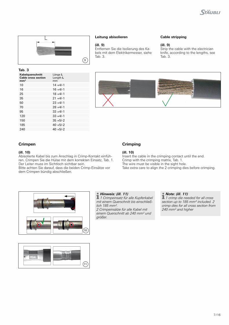
Tab. 3Kabelquerschnitt Cable cross sectionmm2
Länge L Length Lmm
10 14 +4/-116 16 +4/-125 18 +4/-135 21 +4/-150 23 +4/-170 28 +4/-195 33 +4/-1120 33 +4/-1150 35 +5/-2185 40 +5/-2240 40 +5/-2
Leitung abisolieren Cable stripping
(ill. 9)Entfernen Sie die Isolierung des Ka-bels mit dem Elektrikermesser, siehe Tab� 3�
(ill. 9)Strip the cable with the electrician knife, according to the lengths, see Tab� 3�
Hinweis: (ill. 11) 1 Crimpeinsatz für alle Kupferkabel
mit einem Querschnitt bis einschließ-lich 185 mm². 2 Crimpeinsätze für alle Kabel mit einem Querschnitt ab 240 mm² und größer�
Note: (ill. 11) 1 crimp die needed for all cross
section up to 185 mm² included. 2 crimp dies for all cross section from 240 mm² and higher
Crimpen Crimping
(ill. 10)Abisolierte Kabel bis zum Anschlag in Crimp-Kontakt einfüh-ren� Crimpen Sie die Hülse mit dem korrekten Einsatz, Tab� 1�Der Leiter muss im Sichtloch sichtbar sein�Bitte achten Sie darauf, dass die beiden Crimp-Einsätze vor dem Crimpen bündig abschließen�
(ill. 10)Insert the cable in the crimping contact until the end� Crimp with the crimping matrix, Tab� 1�The wire must be visible in the sight hole� Take extra care to align the 2 crimping dies before crimping�
8 / 16
A B AB
C CD
E
13
12
F
H G
EF
DHG
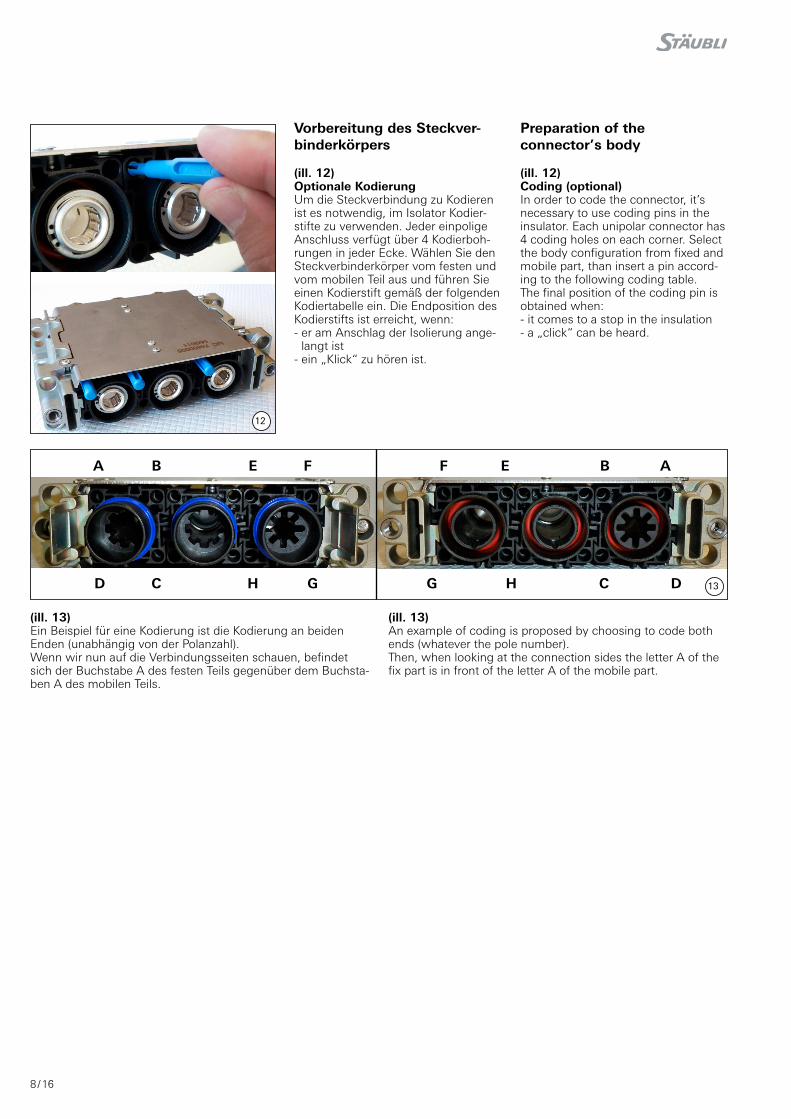
Vorbereitung des Steckver-binderkörpers
Preparation of the connector’s body
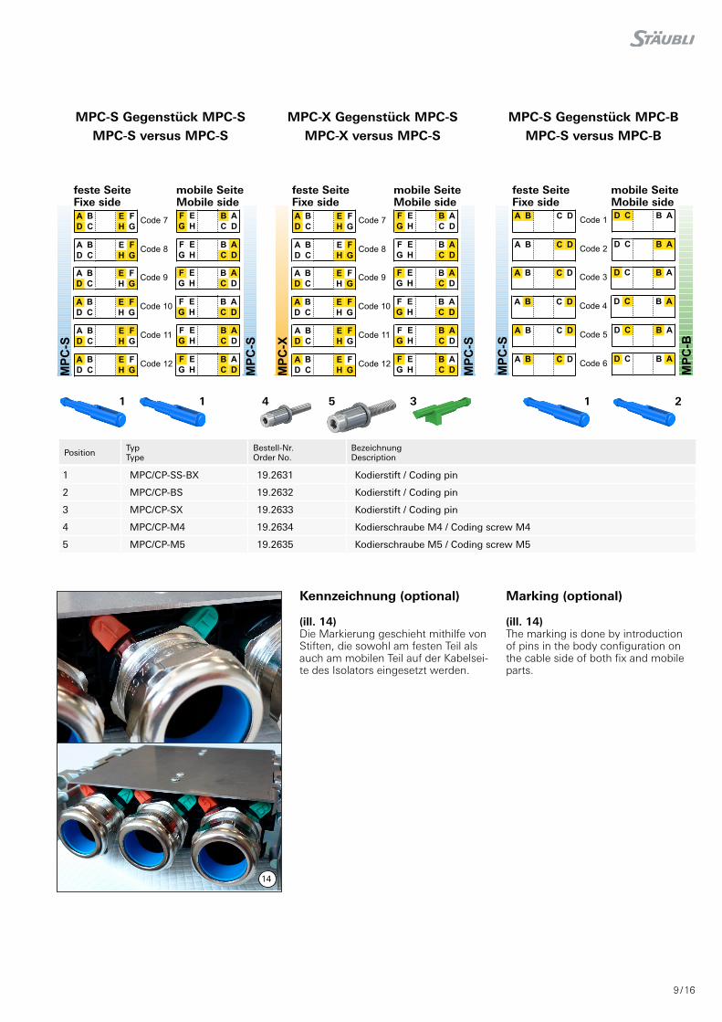
(ill. 12)Optionale KodierungUm die Steckverbindung zu Kodieren ist es notwendig, im Isolator Kodier-stifte zu verwenden� Jeder einpolige Anschluss verfügt über 4 Kodierboh-rungen in jeder Ecke� Wählen Sie den Steckverbinderkörper vom festen und vom mobilen Teil aus und führen Sie einen Kodierstift gemäß der folgenden Kodiertabelle ein� Die Endposition des Kodierstifts ist erreicht, wenn: - er am Anschlag der Isolierung ange-
langt ist- ein „Klick“ zu hören ist�
(ill. 12)Coding (optional)In order to code the connector, it’s necessary to use coding pins in the insulator� Each unipolar connector has 4 coding holes on each corner� Select the body configuration from fixed and mobile part, than insert a pin accord-ing to the following coding table�The final position of the coding pin is obtained when:- it comes to a stop in the insulation- a „click“ can be heard�
(ill. 13)Ein Beispiel für eine Kodierung ist die Kodierung an beiden Enden (unabhängig von der Polanzahl)�Wenn wir nun auf die Verbindungsseiten schauen, befindet sich der Buchstabe A des festen Teils gegenüber dem Buchsta-ben A des mobilen Teils�
(ill. 13)An example of coding is proposed by choosing to code both ends (whatever the pole number)�Then, when looking at the connection sides the letter A of the fix part is in front of the letter A of the mobile part.
9 / 16
1 1 4 5 3 1
Advanced Contact Technology
ACode 7
D
B
C
E
H
F
G
ACode 8
D
B
C
E
H
F
G
ACode 9
D
B
C
E
H
F
G
ACode 10
D
B
C
E
H
F
G
ACode 11
D
B
C
E
H
F
G
ACode 12
D
B
C
E
H
F
G
F
G
E
H
B
C
A
D
F
G
E
H
B
C
A
D
F
G
E
H
B
C
A
D
F
G
E
H
B
C
A
D
F
G
E
H
B
C
A
D
F
G
E
H
B
C
A
D
MPC-S versus MPC-S
MPC-S contre-partie MPC-S
Côté fixe
Fixe Side
MP
C-S
Côté mobile
Mobile Side
MP
C-S
ACode 7
D
B
C
E
H
F
G
ACode 8
D
B
C
E
H
F
G
ACode 9
D
B
C
E
H
F
G
ACode 10
D
B
C
E
H
F
G
ACode 11
D
B
C
E
H
F
G
ACode 12
D
B
C
E
H
F
G
F
G
E
H
B
C
A
D
F
G
E
H
B
C
A
D
F
G
E
H
B
C
A
D
F
G
E
H
B
C
A
D
F
G
E
H
B
C
A
D
F
G
E
H
B
C
A
D
MPC-X versus MPC-S
MPC-X contre-partie MPC-S
Côté fixe
Fixe Side
MP
C-X
Côté mobile
Mobile Side
MP
C-S
ACode 1
B C D
ACode 2
B C D
ACode 3
B C D
ACode 4
B C D
ACode 5
B C D
ACode 6
B C D
D C B A
D C B A
D C B A
D C B A
D C B A
D C B A
MPC-S versus MPC-B
MPC-S contre-partie MPC-B
Côté fixe
Fixe Side
MP
C-B
Côté mobile
Mobile Side
MP
C-S
3. Preparation of the body of theconnector
3. Préparation du corps de connecteur
3.1. Coding (optional) 3.1. Codage (en option)Coding the connector is done by the introduction of pins withclips into the bodies of the connectors, both on the fixe and themobles side. Each pole has insulation on the connection sidewith 4 holes in each corner to snap a piece of coding.Select the connector body to the fixed and mobile, then insert apin according to the association described in the table below.The final position of the peg is obtained> when it comes to a stop in the insulation> when à “click” sound is produced.
Le codage consiste à utiliser des pions qui seront à introduiredans les corps de connecteur, à fois coté fixe et coté mobile.Chaque isolant unipolaire possède sur la face de connexion 4trous dans chacun des angles afin de clipser un pion de codage.Choisir les corps de connecteur pour la partie fixe et mobile,puis introduire un pion selon l’association.La position finale du pion est obtenu> lorsqu’il arrive en butée dans l’isolant,> lorsqu’un “clic” sonore est obtenu.
An example of a coding scheme is proposed by choosing thetwo lines of code contats the 2 ends (whatever the number ofpoles).Thus, looking at the connection faces, the letter A of the fixedpart will be contrasted with the letter A of the mobile part.
Un exemple de système de codage est proposé en choisissantde coder les deux lignes de contacts des 2 extrémités (quelquesoit le nombre de pôles).Ainsi, en regardant les faces de connexion. la lettre A de la par-tie fixe sera mise en opposition avec la lettre A de la partiemobile.
A B E F
D C H G
F E B A
D C H G
1 1 3 1 24
5
TypeType
Order NoNo. de Cde
DescriptionDésignation
1 MPC/CP-SS-BX 19.2631 Coding pin/Pion de codage
2 MPC/CP-BS 19.2632 Coding pin/Pion de codage
3 MPC/CP-SX 19.2633 Coding pin/Pion de codage
4 MPC/CP-M4 19.2634 Coding screw-M4/Vis de codage-M4
5 MPC/CP-M5 19.2635 Coding screw-M5/Vis de codage-M5
PositionPosition
2
14
Position TypType
Bestell-Nr. Order No.
Bezeichnung Description
1 MPC/CP-SS-BX 19.2631 Kodierstift / Coding pin
2 MPC/CP-BS 19.2632 Kodierstift / Coding pin
3 MPC/CP-SX 19.2633 Kodierstift / Coding pin
4 MPC/CP-M4 19.2634 Kodierschraube M4 / Coding screw M4
5 MPC/CP-M5 19.2635 Kodierschraube M5 / Coding screw M5
MPC-S Gegenstück MPC-SMPC-S versus MPC-S
MPC-X Gegenstück MPC-SMPC-X versus MPC-S
MPC-S Gegenstück MPC-BMPC-S versus MPC-B
feste Seite Fixe side
mobile SeiteMobile side
feste Seite Fixe side
mobile Seite Mobile side
feste Seite Fixe side
mobile SeiteMobile side
Kennzeichnung (optional) Marking (optional)
(ill. 14)Die Markierung geschieht mithilfe von Stiften, die sowohl am festen Teil als auch am mobilen Teil auf der Kabelsei-te des Isolators eingesetzt werden�
(ill. 14)The marking is done by introduction of pins in the body configuration on the cable side of both fix and mobile parts�
10 / 16
16
17
15
Typ
Typ
e
Ko
nta
kt-Ø
Co
nta
ct Ø
Bes
tell-
Nr.
Ord
er N
o.
Ref
eren
z R
efer
ence
Bez
iech
nu
ng
D
escr
ipti
on
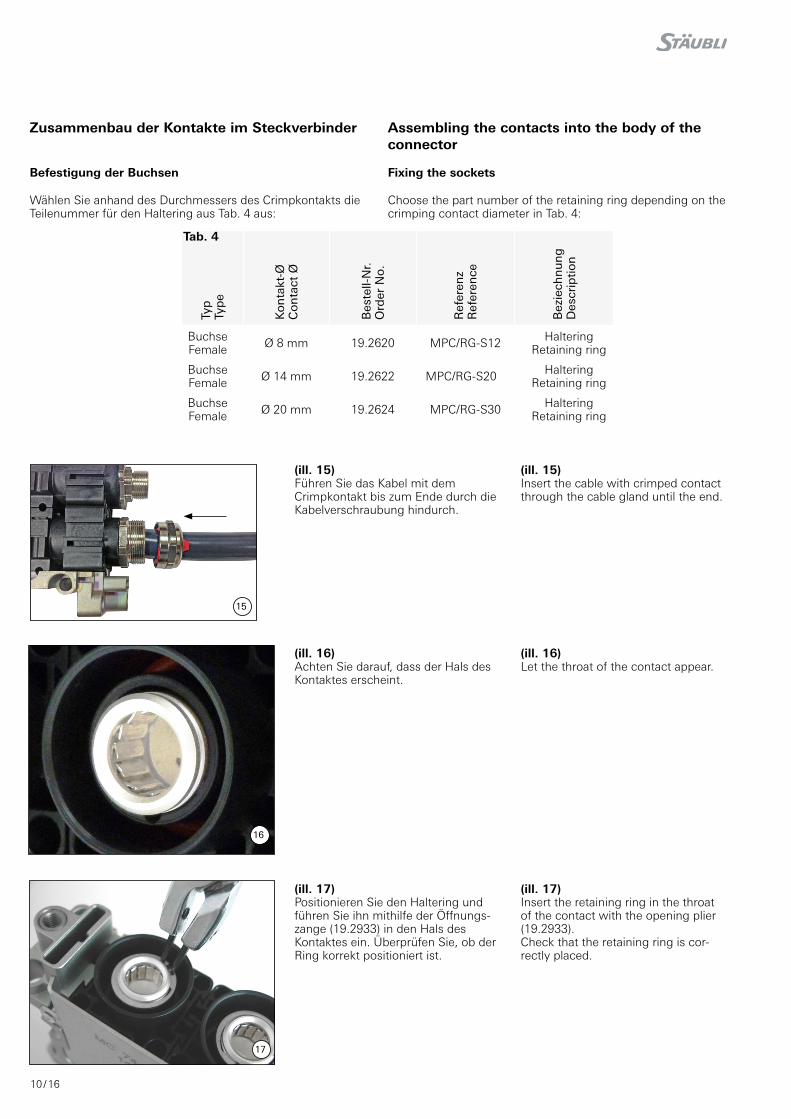
BuchseFemale Ø 8 mm 19�2620 MPC/RG-S12 Haltering
Retaining ring
BuchseFemale Ø 14 mm 19�2622 MPC/RG-S20 Haltering
Retaining ring
BuchseFemale Ø 20 mm 19�2624 MPC/RG-S30 Haltering
Retaining ring
Zusammenbau der Kontakte im Steckverbinder Assembling the contacts into the body of the connector
Befestigung der Buchsen Fixing the sockets
Wählen Sie anhand des Durchmessers des Crimpkontakts die Teilenummer für den Haltering aus Tab� 4 aus:
Choose the part number of the retaining ring depending on the crimping contact diameter in Tab� 4:
(ill. 15)Führen Sie das Kabel mit dem Crimpkontakt bis zum Ende durch die Kabelverschraubung hindurch�
(ill. 15)Insert the cable with crimped contact through the cable gland until the end�
(ill. 16)Achten Sie darauf, dass der Hals des Kontaktes erscheint�
(ill. 16)Let the throat of the contact appear�
(ill. 17)Positionieren Sie den Haltering und führen Sie ihn mithilfe der Öffnungs-zange (19�2933) in den Hals des Kontaktes ein� Überprüfen Sie, ob der Ring korrekt positioniert ist�
(ill. 17)Insert the retaining ring in the throat of the contact with the opening plier (19�2933)�Check that the retaining ring is cor-rectly placed�
Tab. 4
11 / 16
20
19
18
21
Typ
Typ
e
Ko
nta
kt Ø
Co
nta
ct Ø
Bes
tell-
Nr.
Ord
er N
o.
Ref
eren
z R
efer
ence
Bez
eich
nu
ng
D
escr
ipti
on
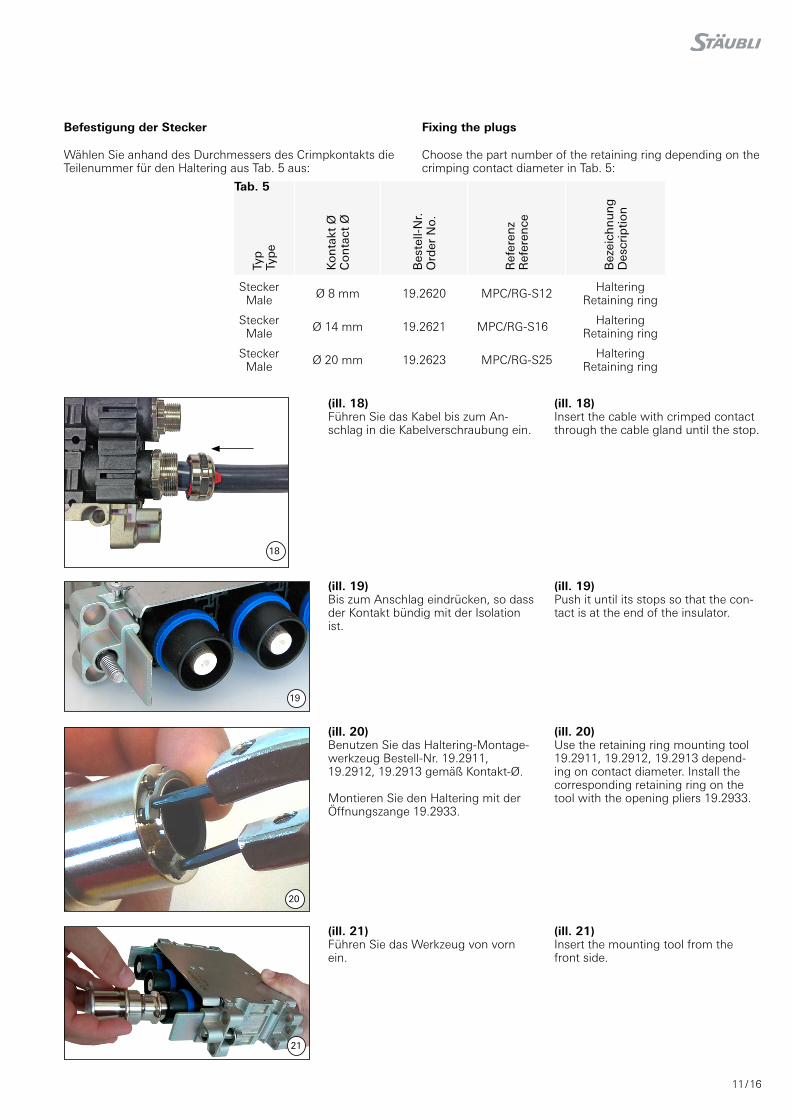
SteckerMale Ø 8 mm 19�2620 MPC/RG-S12 Haltering
Retaining ring
SteckerMale Ø 14 mm 19�2621 MPC/RG-S16 Haltering
Retaining ring
SteckerMale Ø 20 mm 19�2623 MPC/RG-S25 Haltering
Retaining ring
(ill. 18)Führen Sie das Kabel bis zum An-schlag in die Kabelverschraubung ein�
(ill. 18)Insert the cable with crimped contact through the cable gland until the stop�
(ill. 19)Bis zum Anschlag eindrücken, so dass der Kontakt bündig mit der Isolation ist�
(ill. 19)Push it until its stops so that the con-tact is at the end of the insulator�
(ill. 20)Benutzen Sie das Haltering-Montage-werkzeug Bestell-Nr� 19�2911, 19�2912, 19�2913 gemäß Kontakt-Ø�
Montieren Sie den Haltering mit der Öffnungszange 19�2933�
(ill. 20)Use the retaining ring mounting tool 19�2911, 19�2912, 19�2913 depend-ing on contact diameter� Install the correspond ing retaining ring on the tool with the opening pliers 19�2933�
(ill. 21)Führen Sie das Werkzeug von vorn ein�
(ill. 21)Insert the mounting tool from the front side�
Befestigung der Stecker Fixing the plugs
Wählen Sie anhand des Durchmessers des Crimpkontakts die Teilenummer für den Haltering aus Tab� 5 aus:
Choose the part number of the retaining ring depending on the crimping contact diameter in Tab� 5:
Tab. 5
12 / 16
22
23
24
25
26
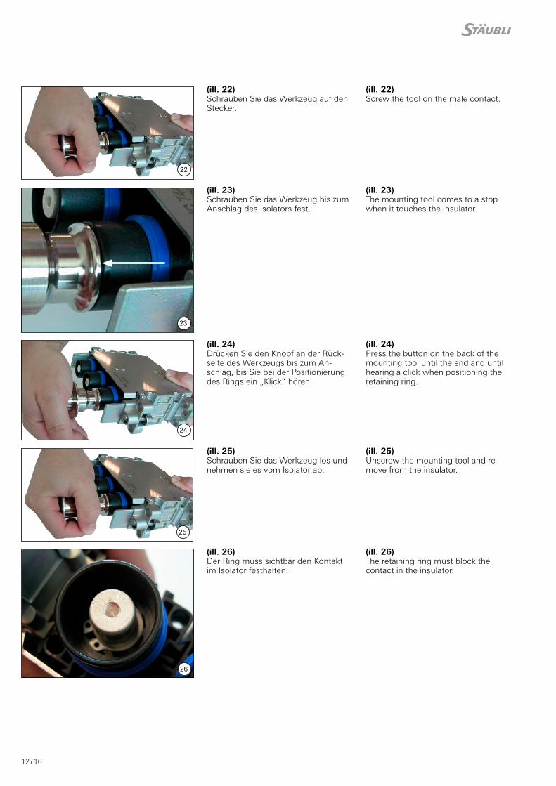
(ill. 22)Schrauben Sie das Werkzeug auf den Stecker�
(ill. 22)Screw the tool on the male contact�
(ill. 23)Schrauben Sie das Werkzeug bis zum Anschlag des Isolators fest�
(ill. 23)The mounting tool comes to a stop when it touches the insulator�
(ill. 24)Drücken Sie den Knopf an der Rück-seite des Werkzeugs bis zum An-schlag, bis Sie bei der Positionierung des Rings ein „Klick“ hören�
(ill. 24)Press the button on the back of the mounting tool until the end and until hearing a click when positioning the retaining ring�
(ill. 25)Schrauben Sie das Werkzeug los und nehmen sie es vom Isolator ab�
(ill. 25)Unscrew the mounting tool and re-move from the insulator�
(ill. 26)Der Ring muss sichtbar den Kontakt im Isolator festhalten�
(ill. 26)The retaining ring must block the contact in the insulator�
13 / 16
28
27
11 mm
29
30
X
Y
D
Tab. 6
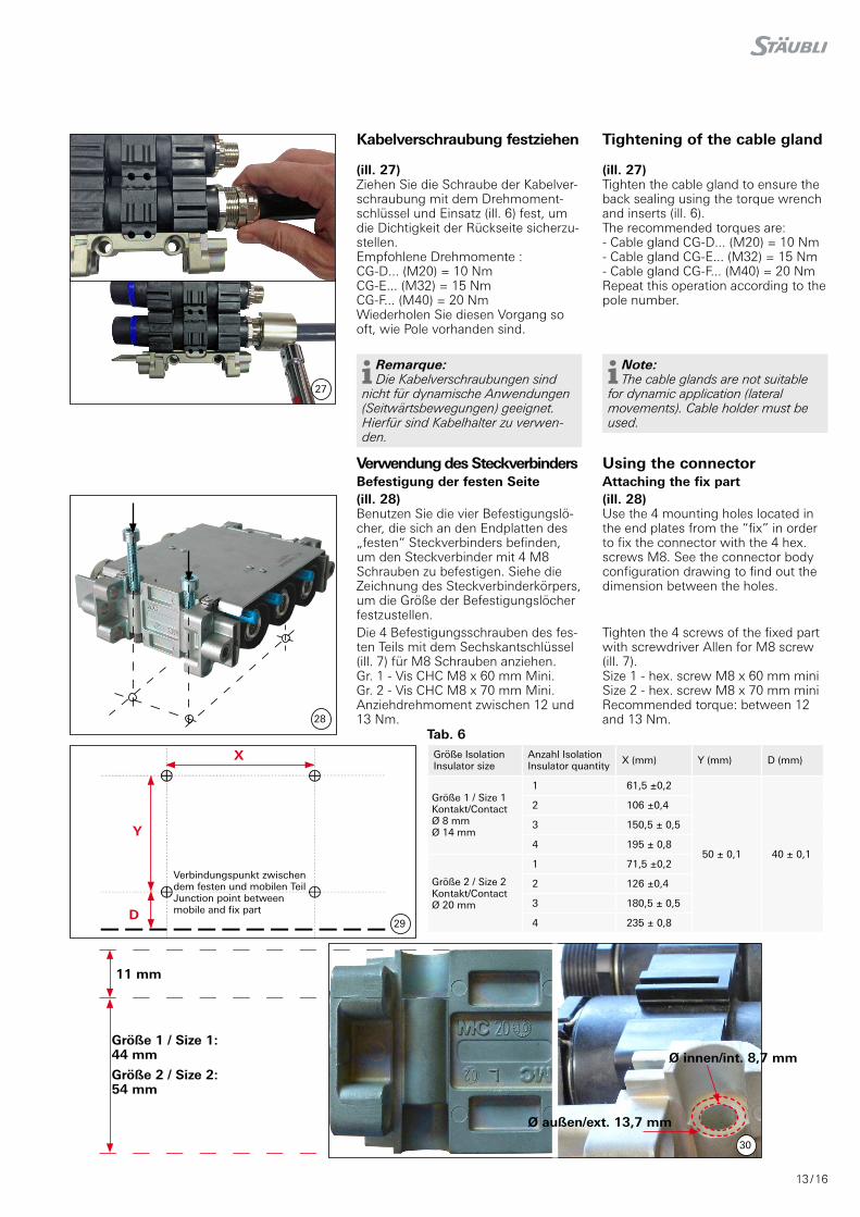
Kabelverschraubung festziehen Tightening of the cable gland
(ill. 27)Ziehen Sie die Schraube der Kabelver-schraubung mit dem Drehmoment-schlüssel und Einsatz (ill� 6) fest, um die Dichtigkeit der Rückseite sicherzu-stellen� Empfohlene Drehmomente : CG-D... (M20) = 10 NmCG-E... (M32) = 15 NmCG-F... (M40) = 20 NmWiederholen Sie diesen Vorgang so oft, wie Pole vorhanden sind�
(ill. 27)Tighten the cable gland to ensure the back sealing using the torque wrench and inserts (ill� 6)� The recommended torques are:- Cable gland CG-D... (M20) = 10 Nm- Cable gland CG-E... (M32) = 15 Nm- Cable gland CG-F... (M40) = 20 NmRepeat this operation according to the pole number�
Remarque: Die Kabelverschraubungen sind
nicht für dynamische Anwendungen (Seitwärtsbewegungen) geeignet� Hierfür sind Kabelhalter zu verwen-den�
Note: The cable glands are not suitable
for dynamic application (lateral movements)� Cable holder must be used�
Verwendung des Steckverbinders Using the connectorBefestigung der festen Seite Attaching the fix part(ill. 28)Benutzen Sie die vier Befestigungslö-cher, die sich an den Endplatten des „festen“ Steckverbinders befinden, um den Steckverbinder mit 4 M8 Schrauben zu befestigen� Siehe die Zeichnung des Steckverbinderkörpers, um die Größe der Befestigungslöcher festzustellen�
(ill. 28)Use the 4 mounting holes located in the end plates from the “fix” in order to fix the connector with the 4 hex. screws M8� See the connector body configuration drawing to find out the dimension between the holes�
Die 4 Befestigungsschrauben des fes-ten Teils mit dem Sechskantschlüssel (ill� 7) für M8 Schrauben anziehen�Gr. 1 - Vis CHC M8 x 60 mm Mini.Gr. 2 - Vis CHC M8 x 70 mm Mini.Anziehdrehmoment zwischen 12 und 13 Nm.
Tighten the 4 screws of the fixed part with screwdriver Allen for M8 screw (ill� 7)�Size 1 - hex. screw M8 x 60 mm miniSize 2 - hex. screw M8 x 70 mm miniRecommended torque: between 12 and 13 Nm.
Verbindungspunkt zwischen dem festen und mobilen Teil Junction point between mobile and fix part
Größe IsolationInsulator size
Anzahl IsolationInsulator quantity X (mm) Y (mm) D (mm)
Größe 1 / Size 1Kontakt/Contact Ø 8 mm Ø 14 mm
1 61,5 ±0,2
50 ± 0,1 40 ± 0,1
2 106 ±0,4
3 150,5 ± 0,5
4 195 ± 0,8
Größe 2 / Size 2Kontakt/Contact Ø 20 mm
1 71,5 ±0,2
2 126 ±0,4
3 180,5 ± 0,5
4 235 ± 0,8
Größe 1 / Size 1: 44 mm
Größe 2 / Size 2: 54 mm
Ø außen/ext. 13,7 mm
Ø innen/int. 8,7 mm
14 / 16
31
32
33
34
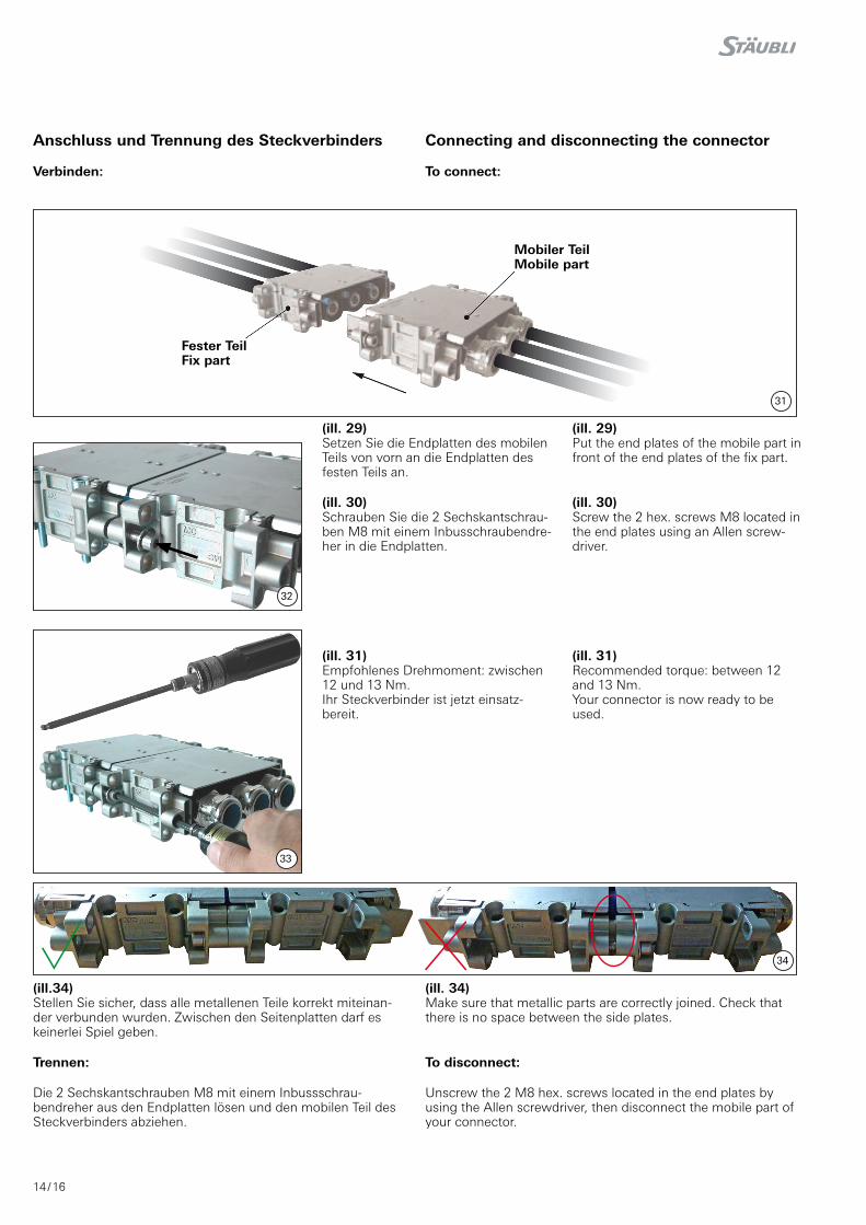
(ill. 29)Setzen Sie die Endplatten des mobilen Teils von vorn an die Endplatten des festen Teils an�
(ill. 29)Put the end plates of the mobile part in front of the end plates of the fix part.
(ill. 30)Schrauben Sie die 2 Sechskantschrau-ben M8 mit einem Inbusschraubendre-her in die Endplatten�
(ill. 30)Screw the 2 hex� screws M8 located in the end plates using an Allen screw-driver�
(ill. 31)Empfohlenes Drehmoment: zwischen 12 und 13 Nm.Ihr Steckverbinder ist jetzt einsatz-bereit�
(ill. 31)Recommended torque: between 12 and 13 Nm.Your connector is now ready to be used�
Anschluss und Trennung des Steckverbinders Connecting and disconnecting the connector
Verbinden: To connect:
Fester TeilFix part
Mobiler Teil Mobile part
(ill.34)Stellen Sie sicher, dass alle metallenen Teile korrekt miteinan-der verbunden wurden� Zwischen den Seitenplatten darf es keinerlei Spiel geben�
(ill. 34)Make sure that metallic parts are correctly joined� Check that there is no space between the side plates�
Trennen: To disconnect:
Die 2 Sechskantschrauben M8 mit einem Inbussschrau-bendreher aus den Endplatten lösen und den mobilen Teil des Steckverbinders abziehen�
Unscrew the 2 M8 hex� screws located in the end plates by using the Allen screwdriver, then disconnect the mobile part of your connector�
15 / 16
35
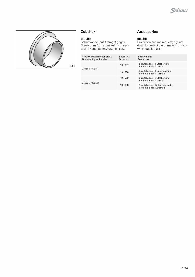
Steckverbinderkörper Größe Body configuration size
Bestell-Nr.Order no.
BezeichnungDescription
Größe 1 / Size 1
19.2667 Schutzkappe T1 SteckerseiteProtection cap T1 male
19.2668 Schutzkappe T1 BuchsenseiteProtection cap T1 female
Größe 2 / Size 2
19.2669 Schutzkappe T2 SteckerseiteProtection cap T2 male
19.2663 Schutzkappen T2 BuchsenseiteProtection cap T2 female
Zubehör Accessories
(ill. 35)Schutzkappe (auf Anfrage) gegen Staub, zum Aufsetzen auf nicht ges-teckte Kontakte im Außeneinsatz�
(ill. 35)Protection cap (on request) against dust� To protect the unmated contacts when outside use�

16 / 16
Hersteller/Producer: Stäubli Electrical Connectors AG Stockbrunnenrain 8 4123 Allschwil/Switzerland Tel. +41 61 306 55 55 Fax +41 61 306 55 56 mail [email protected] www.staubli.com/electrical ©
by
Stä
ub
li Ele
ctri
cal C
on
nec
tors
AG
, S
wit
zerl
and
– M
A0
82
– 0
9.2
01
9,
Ind
ex d
, Mar
ketin
g C
omm
unic
atio
ns –
Änd
erun
gen
vor
beha
lten
/ Sub
ject
to
alte
ratio
ns
Notizen / Notes: