Embed Size (px)
Citation preview
�0 WX1 V.�008/9
KanalventilatorenDuct Fans Preisliste Seite / Price List Page 2-5
EK, DK, EKS, DKS
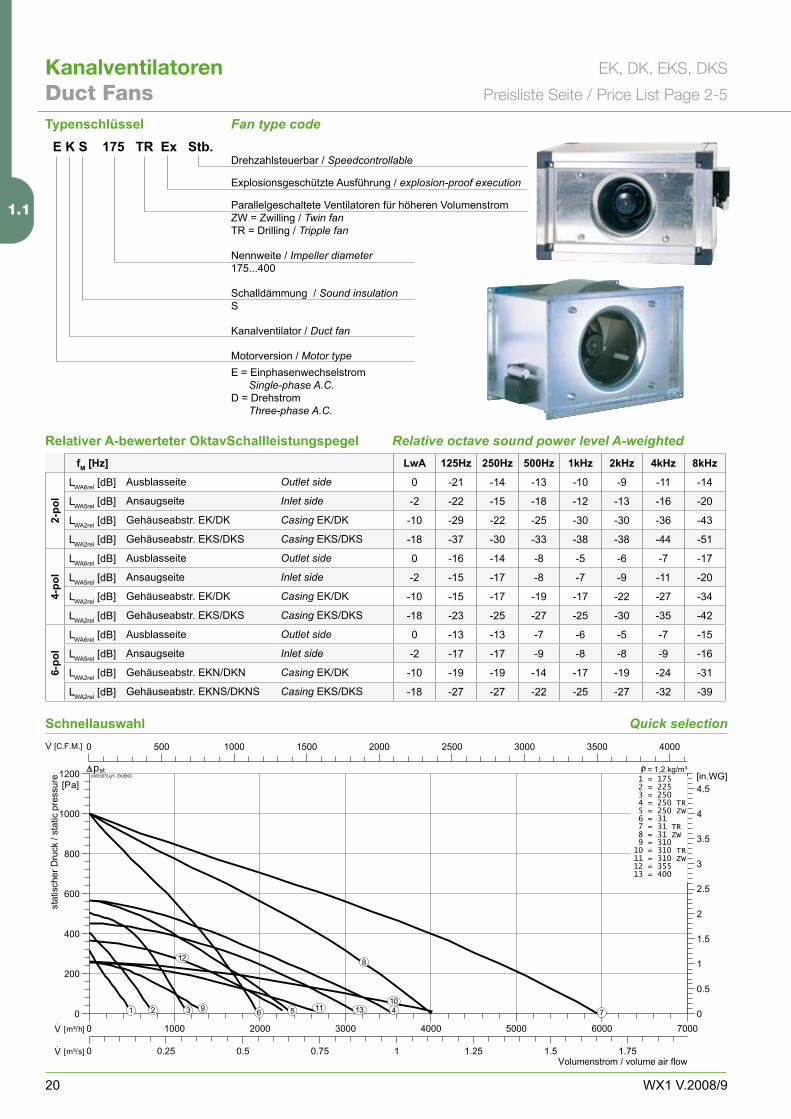
Fan type code
Quick selection
Relative octave sound power level A-weighted
E K S 175 TR Ex Stb.Drehzahlsteuerbar / Speedcontrollable
Explosionsgeschützte Ausführung / explosion-proof execution
Parallelgeschaltete Ventilatoren für höheren Volumenstrom ZW = Zwilling / Twin fanTR = Drilling / Tripple fan
Nennweite / Impeller diameter175...�00
Schalldämmung / Sound insulationS
Kanalventilator / Duct fan
Motorversion / Motor typeE = Einphasenwechselstrom Single-phase A.C.D = Drehstrom Three-phase A.C.
Typenschlüssel
0 500 1000 1500 2000 2500 3000 3500 4000·V [C.F.M.]
0 0.25 0.5 0.75 1 1.25 1.5 1.75·V [m³/s]
0 1000 2000 3000 4000 5000 6000 7000·V [m³/h]
0
0.5
1
1.5
2
2.5
3
3.5
4
4.5[in.WG]
0
200
400
600
800
1000
1200[Pa]
Volumenstrom / volume air flow
statischer
Druck
/static
pressure cW012P2.grf - EK/EKS
stp = 1,2 kg/m³1 = 1752 = 2253 = 2504 = 250 TR5 = 250 ZW6 = 317 = 31 TR8 = 31 ZW9 = 31010 = 310 TR11 = 310 ZW12 = 35513 = 400
1 2 3 456 7
8
910
11
12
13
Schnellauswahl
fM [Hz] LwA 125Hz 250Hz 500Hz 1kHz 2kHz 4kHz 8kHz
2-po
l
LWA6rel [dB] Ausblasseite Outlet side 0 -�1 -1� -1� -10 -9 -11 -1�
LWA5rel [dB] Ansaugseite Inlet side -� -�� -15 -18 -1� -1� -16 -�0
LWA�rel [dB] Gehäuseabstr. EK/DK Casing EK/DK -10 -�9 -�� -�5 -�0 -�0 -�6 -��
LWA�rel [dB] Gehäuseabstr. EKS/DKS Casing EKS/DKS -18 -�7 -�0 -�� -�8 -�8 -�� -51
4-po
l
LWA6rel [dB] Ausblasseite Outlet side 0 -16 -1� -8 -5 -6 -7 -17
LWA5rel [dB] Ansaugseite Inlet side -� -15 -17 -8 -7 -9 -11 -�0
LWA�rel [dB] Gehäuseabstr. EK/DK Casing EK/DK -10 -15 -17 -19 -17 -�� -�7 -��
LWA�rel [dB] Gehäuseabstr. EKS/DKS Casing EKS/DKS -18 -�� -�5 -�7 -�5 -�0 -�5 -��
6-po
l
LWA6rel [dB] Ausblasseite Outlet side 0 -1� -1� -7 -6 -5 -7 -15
LWA5rel [dB] Ansaugseite Inlet side -� -17 -17 -9 -8 -8 -9 -16
LWA�rel [dB] Gehäuseabstr. EKN/DKN Casing EK/DK -10 -19 -19 -1� -17 -19 -�� -�1
LWA�rel [dB] Gehäuseabstr. EKNS/DKNS Casing EKS/DKS -18 -�7 -�7 -�� -�5 -�7 -�� -�9
Relativer A-bewerteter OktavSchallleistungspegel
1.1
�1WX1 V.�008/9
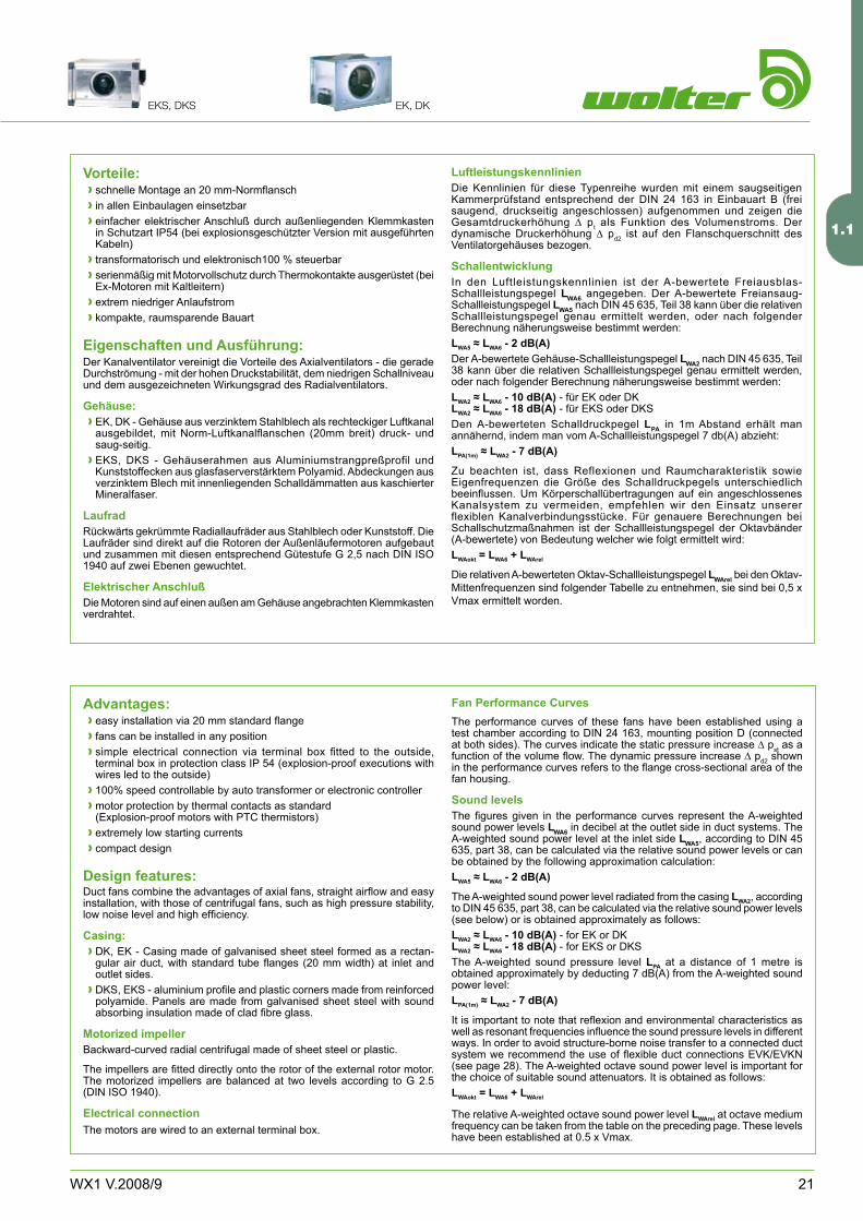
!"EKS, DKS EK, DK
Advantages:easy installation via 20 mm standard flangefans can be installed in any positionsimple electrical connection via terminal box fitted to the outside, terminal box in protection class IP 5� (explosion-proof executions with wires led to the outside)100% speed controllable by auto transformer or electronic controllermotor protection by thermal contacts as standard (Explosion-proof motors with PTC thermistors)extremely low starting currentscompact design
Design features:Duct fans combine the advantages of axial fans, straight airflow and easy installation, with those of centrifugal fans, such as high pressure stability, low noise level and high efficiency.
Casing:DK, EK - Casing made of galvanised sheet steel formed as a rectan-gular air duct, with standard tube flanges (20 mm width) at inlet and outlet sides.DKS, EKS - aluminium profile and plastic corners made from reinforced polyamide. Panels are made from galvanised sheet steel with sound absorbing insulation made of clad fibre glass.
Motorized impellerBackward-curved radial centrifugal made of sheet steel or plastic.
The impellers are fitted directly onto the rotor of the external rotor motor. The motorized impellers are balanced at two levels according to G �.5 (DIN ISO 19�0).
Electrical connectionThe motors are wired to an external terminal box.
>>>
>>
>>
>
>
Fan Performance CurvesThe performance curves of these fans have been established using a test chamber according to DIN �� 16�, mounting position D (connected at both sides). The curves indicate the static pressure increase D pst as a function of the volume flow. The dynamic pressure increase D pd� shown in the performance curves refers to the flange cross-sectional area of the fan housing.
Sound levelsThe figures given in the performance curves represent the A-weighted sound power levels LWA6 in decibel at the outlet side in duct systems. The A-weighted sound power level at the inlet side LWA5, according to DIN �5 6�5, part �8, can be calculated via the relative sound power levels or can be obtained by the following approximation calculation:LWA5 ≈ LWA6 - 2 dB(A)
The A-weighted sound power level radiated from the casing LWA2, according to DIN �5 6�5, part �8, can be calculated via the relative sound power levels (see below) or is obtained approximately as follows:LWA2 ≈ LWA6 - 10 dB(A) - for EK or DKLWA2 ≈ LWA6 - 18 dB(A) - for EKS or DKSThe A-weighted sound pressure level LPA at a distance of 1 metre is obtained approximately by deducting 7 dB(A) from the A-weighted sound power level:LPA(1m) ≈ LWA2 - 7 dB(A)
It is important to note that reflexion and environmental characteristics as well as resonant frequencies influence the sound pressure levels in different ways. In order to avoid structure-borne noise transfer to a connected duct system we recommend the use of flexible duct connections EVK/EVKN (see page �8). The A-weighted octave sound power level is important for the choice of suitable sound attenuators. It is obtained as follows:LWAokt = LWA6 + LWArel
The relative A-weighted octave sound power level LWArel at octave medium frequency can be taken from the table on the preceding page. These levels have been established at 0.5 x Vmax.
Vorteile:schnelle Montage an 20 mm-Normflanschin allen Einbaulagen einsetzbareinfacher elektrischer Anschluß durch außenliegenden Klemmkasten in Schutzart IP5� (bei explosionsgeschützter Version mit ausgeführten Kabeln)transformatorisch und elektronisch100 % steuerbarserienmäßig mit Motorvollschutz durch Thermokontakte ausgerüstet (bei Ex-Motoren mit Kaltleitern)extrem niedriger Anlaufstromkompakte, raumsparende Bauart
Eigenschaften und Ausführung:Der Kanalventilator vereinigt die Vorteile des Axialventilators - die gerade Durchströmung - mit der hohen Druckstabilität, dem niedrigen Schallniveau und dem ausgezeichneten Wirkungsgrad des Radialventilators.
Gehäuse:EK, DK - Gehäuse aus verzinktem Stahlblech als rechteckiger Luftkanal ausgebildet, mit Norm-Luftkanalflanschen (20mm breit) druck- und saug-seitig.EKS, DKS - Gehäuserahmen aus Aluminiumstrangpreßprofil und Kunststoffecken aus glasfaserverstärktem Polyamid. Abdeckungen aus verzinktem Blech mit innenliegenden Schalldämmatten aus kaschierter Mineralfaser.
LaufradRückwärts gekrümmte Radiallaufräder aus Stahlblech oder Kunststoff. Die Laufräder sind direkt auf die Rotoren der Außenläufermotoren aufgebaut und zusammen mit diesen entsprechend Gütestufe G �,5 nach DIN ISO 19�0 auf zwei Ebenen gewuchtet.
Elektrischer AnschlußDie Motoren sind auf einen außen am Gehäuse angebrachten Klemmkasten verdrahtet.
>>>
>>
>>
>
>
LuftleistungskennlinienDie Kennlinien für diese Typenreihe wurden mit einem saugseitigen Kammerprüfstand entsprechend der DIN �� 16� in Einbauart B (frei saugend, druckseitig angeschlossen) aufgenommen und zeigen die Gesamtdruckerhöhung D pt als Funktion des Volumenstroms. Der dynamische Druckerhöhung D pd� ist auf den Flanschquerschnitt des Ventilatorgehäuses bezogen.
SchallentwicklungIn den Luftleistungskennlinien ist der A-bewertete Freiausblas-Schallleistungspegel LWA6 angegeben. Der A-bewertete Freiansaug-Schallleistungspegel LWA5 nach DIN �5 6�5, Teil �8 kann über die relativen Schallleistungspegel genau ermittelt werden, oder nach folgender Berechnung näherungsweise bestimmt werden:LWA5 ≈ LWA6 - 2 dB(A)Der A-bewertete Gehäuse-Schallleistungspegel LWA2 nach DIN �5 6�5, Teil �8 kann über die relativen Schallleistungspegel genau ermittelt werden, oder nach folgender Berechnung näherungsweise bestimmt werden:LWA2 ≈ LWA6 - 10 dB(A) - für EK oder DKLWA2 ≈ LWA6 - 18 dB(A) - für EKS oder DKSDen A-bewerteten Schalldruckpegel LPA in 1m Abstand erhält man annähernd, indem man vom A-Schallleistungspegel 7 db(A) abzieht:LPA(1m) ≈ LWA2 - 7 dB(A)
Zu beachten ist, dass Reflexionen und Raumcharakteristik sowie Eigenfrequenzen die Größe des Schalldruckpegels unterschiedlich beeinflussen. Um Körperschallübertragungen auf ein angeschlossenes Kanalsystem zu vermeiden, empfehlen wir den Einsatz unserer flexiblen Kanalverbindungsstücke. Für genauere Berechnungen bei Schallschutzmaßnahmen ist der Schallleistungspegel der Oktavbänder (A-bewertete) von Bedeutung welcher wie folgt ermittelt wird:LWAokt = LWA6 + LWArel
Die relativen A-bewerteten Oktav-Schallleistungspegel LWArel bei den Oktav-Mittenfrequenzen sind folgender Tabelle zu entnehmen, sie sind bei 0,5 x Vmax ermittelt worden.
1.1
�� WX1 V.�008/9
KanalventilatorenDuct Fans
EK, DK, EKS, DKS
Preisliste Seite / Price List Page 2-5
Typ :
Art. Nr :
) [kg]:
U :
P1 [kW]:
IN [A]:
n [min-1]:
C400V [µF]:
tR [°C]:
45-,*
Typ :
Art. Nr :
) [kg]:
U :
P1 [kW]:
IN [A]:
n [min-1]:
C400V [µF]:
tR [°C]:
45-,*
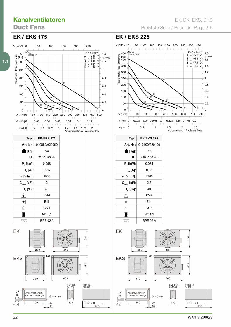
EK / EKS 175
EK/EKS 175
010050/0�0050
6/8
��0 V 50 Hz
0,058
0,�6
�500
�
�0
IP��
E11
GS 1
NE 1,5
RPE 0� A
EK / EKS 225
EK/EKS 225
010100/0�0100
7/10
��0 V 50 Hz
0,085
0,�8
�700
�,5
�0
IP��
E11
GS 1
NE 1,5
RPE 0� A
0 0.25 0.5 0.75 1 1.25 1.5 1.75 2c [m/s]
0 50 100 150 200 250·V [C.F.M.]
0 0.02 0.04 0.06 0.08 0.1 0.12·V [m³/s]
0 50 100 150 200 250 300 350 400 450 500·V [m³/h]
0
0.2
0.4
0.6
0.8
1
1.2
1.4[in.WG]
0
50
100
150
200
250
300
350[Pa]
Volumenstrom / volume flow
Totaldruck
/total
pres
sure 010050 EK 175
totp = 1,2 kg/m³1 = 220 V2 = 160 V3 = 130 V4 = 105 V5 = 60 V
65
6659
59
56
56505144
4412345
0 0.5 1 1.5 2 2.5c [m/s]
0 50 100 150 200 250 300 350 400 450·V [C.F.M.]
0 0.025 0.05 0.075 0.1 0.125 0.15 0.175 0.2·V [m³/s]
0 100 200 300 400 500 600 700 800·V [m³/h]
0
0.2
0.4
0.6
0.8
1
1.2
1.4
1.6
1.8[in.WG]
0
50
100
150
200
250
300
350
400
450[Pa]
Volumenstrom / volume flow
Totaldruck
/total
pres
sure 010100 EK 225
totp = 1,2 kg/m³1 = 220 V2 = 160 V3 = 130 V4 = 105 V5 = 60 V
69
7461
6759
64525746
5012345
250 415
350
18
0
26
0
280 450
28
0
EVK 175 S DK 175041050 043050
250 460
400
21
0
26
0
310 500
31
0
EVK 250 S DK 250041100 043100
1.1
��WX1 V.�008/9
!"EKS, DKS EK, DK
Typ :
Art. Nr :
) [kg]:
U :
P1 [kW]:
IN [A]:
n [min-1]:
C400V [µF]:
tR [°C]:
45-,*
Typ :
Art. Nr :
) [kg]:
U :
P1 [kW]:
IN [A]:
n [min-1]:
C400V [µF]:
tR [°C]:
45-,*
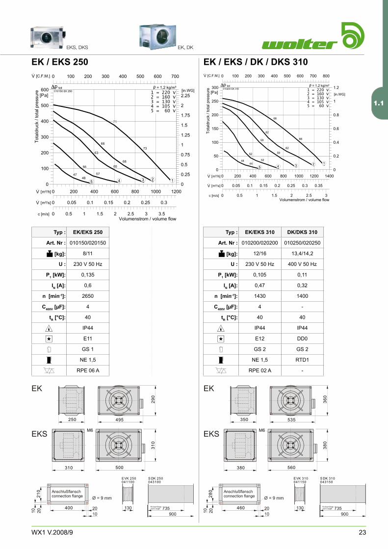
EK / EKS 250
EK/EKS 250
010150/0�0150
8/11
��0 V 50 Hz
0,1�5
0,6
�650
�
�0
IP��
E11
GS 1
NE 1,5
RPE 06 A
EK / EKS / DK / DKS 310
EK/EKS 310
010�00/0�0�00
1�/16
��0 V 50 Hz
0,105
0,�7
1��0
�
�0
IP��
E1�
GS �
NE 1,5
RPE 0� A
DK/DKS 310
010�50/0�0�50
1�,�/1�,�
�00 V 50 Hz
0,11
0,��
1�00
-
�0
IP��
DD0
GS �
RTD1
-
0 0.5 1 1.5 2 2.5 3 3.5c [m/s]
0 100 200 300 400 500 600 700·V [C.F.M.]
0 0.05 0.1 0.15 0.2 0.25 0.3·V [m³/s]
0 200 400 600 800 1000 1200·V [m³/h]
0
0.25
0.5
0.75
1
1.25
1.5
1.75
2
2.25[in.WG]
0
100
200
300
400
500
600[Pa]
Volumenstrom / volume flow
Tota
ldru
ck/t
otal
pres
sure 010150 EK 250
totp = 1,2 kg/m³1 = 220 V2 = 160 V3 = 130 V4 = 105 V5 = 60 V
71
7366
68
63
6556
574748
12345
0 0.5 1 1.5 2 2.5 3c [m/s]
0 100 200 300 400 500 600 700 800·V [C.F.M.]
0 0.05 0.1 0.15 0.2 0.25 0.3 0.35·V [m³/s]
0 200 400 600 800 1000 1200 1400·V [m³/h]
0
0.2
0.4
0.6
0.8
1
1.2[in.WG]
0
50
100
150
200
250
300[Pa]
Volumenstrom / volume flow
Totaldruck
/total
pres
sure 010200 EK 310
totp = 1,2 kg/m³1 = 220 V2 = 160 V3 = 130 V4 = 105 V5 = 60 V
66
66
62
62
59
5952
524444 12345
250 495
400
21
0
29
0
310 500
31
0
EVK 250 S DK 250041100 043100
350 535
460
28
0
36
0
380 560
38
0
EVK 310 S DK 310041150 043150
1.1
�� WX1 V.�008/9
KanalventilatorenDuct Fans
EK, DK, EKS, DKS
Preisliste Seite / Price List Page 2-5
Typ :
Art. Nr :
) [kg]:
U :
P1 [kW]:
IN [A]:
n [min-1]:
C400V [µF]:
tR [°C]:
45-,*
Typ :
Art. Nr :
) [kg]:
U :
P1 [kW]:
IN [A]:
n [min-1]:
C400V [µF]:
tR [°C]:
45-,*
350 555
460
28
0
36
0
380 560
38
0
EVK 310 S DK 310041150 043150
350 620
520
32
0
42
0
440 620
44
0
EVK 355 S DK 355041200 043200
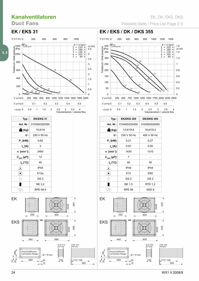
0 0.5 1 1.5 2 2.5 3 3.5 4c [m/s]
0 200 400 600 800 1000·V [C.F.M.]
0 0.1 0.2 0.3 0.4 0.5·V [m³/s]
0 200 400 600 800 1000 1200 1400 1600 1800 2000·V [m³/h]
0
0.5
1
1.5
2
2.5
3
3.5
4
4.5[in.WG]
0
200
400
600
800
1000
1200[Pa]
Volumenstrom / volume flow
Totaldruck
/totalpressure 010350 EK 31
totp = 1,2 kg/m³1 = 220 V2 = 160 V3 = 130 V4 = 105 V5 = 60 V
78
80
65
67606349 523032 12345
0 0.5 1 1.5 2 2.5 3 3.5 4c [m/s]
0 200 400 600 800 1000 1200 1400·V [C.F.M.]
0 0.1 0.2 0.3 0.4 0.5 0.6·V [m³/s]
0 250 500 750 1000 1250 1500 1750 2000 2250 2500·V [m³/h]
0
0.2
0.4
0.6
0.8
1
1.2
1.4
1.6[in.WG]
0
50
100
150
200
250
300
350
400[Pa]
Volumenstrom / volume flow
Totaldruck
/totalpressure 010400 EK 355
totp = 1,2 kg/m³1 = 220 V2 = 160 V3 = 130 V4 = 105 V5 = 60 V
69
73
67
71
66
7061
6453
5712345
EK / EKS 31
EK/EKS 31
010�50/0�0�50
15,6/19
��0 V 50 Hz
0,65
�
��65
1�
�0
IP5�
E1�a
GS �
NE �,�
RPE 09 A
EK / EKS / DK / DKS 355
EK/EKS 355
010�00/0�0�00
1�,6/18,8
��0 V 50 Hz
0,�1
0,97
1��0
7
�0
IP��
E1�
GS �
NE 1,5
RPE 06
DK/DKS 355
010�50/0�0�50
16,6/18,�
�00 V 50 Hz
0,�7
0,55
1�10
-
�0
IP��
DS0
GS �
RTD 1,�
SSD 9
��0
1.1
�5WX1 V.�008/9
!"EKS, DKS EK, DK
Typ :
Art. Nr :
) [kg]:
U :
P1 [kW]:
IN [A]:
n [min-1]:
C400V [µF]:
tR [°C]:
45-,*
Typ :
Art. Nr :
) [kg]:
U :
P1 [kW]:
IN [A]:
n [min-1]:
C400V [µF]:
tR [°C]:
45-,*
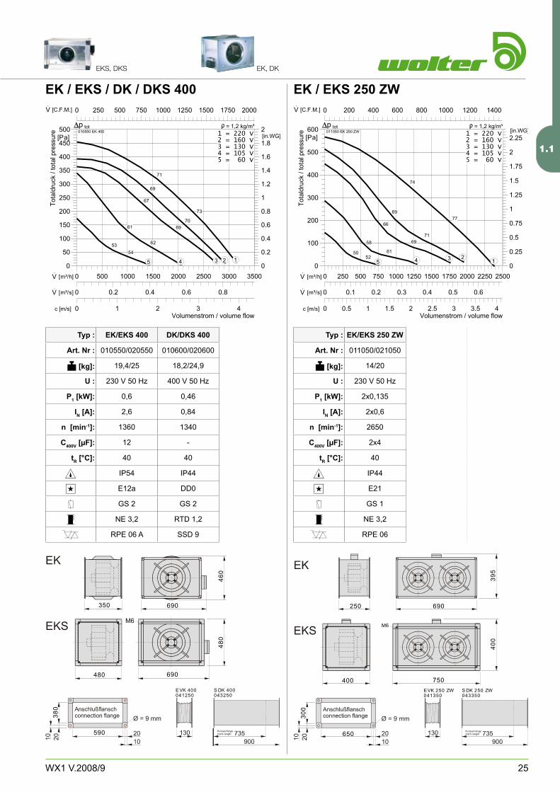
EK / EKS / DK / DKS 400
EK/EKS 400
010550/0�0550
19,�/�5
��0 V 50 Hz
0,6
�,6
1�60
1�
�0
IP5�
E1�a
GS �
NE �,�
RPE 06 A
DK/DKS 400
010600/0�0600
18,�/��,9
�00 V 50 Hz
0,�6
0,8�
1��0
-
�0
IP��
DD0
GS �
RTD 1,�
SSD 9
EK / EKS 250 ZW
EK/EKS 250 ZW
011050/0�1050
1�/�0
��0 V 50 Hz
�x0,1�5
�x0,6
�650
�x�
�0
IP��
E�1
GS 1
NE �,�
RPE 06
0 1 2 3 4c [m/s]
0 250 500 750 1000 1250 1500 1750 2000·V [C.F.M.]
0 0.2 0.4 0.6 0.8·V [m³/s]
0 500 1000 1500 2000 2500 3000 3500·V [m³/h]
0
0.2
0.4
0.6
0.8
1
1.2
1.4
1.6
1.8
2[in.WG]
0
50
100
150
200
250
300
350
400
450
500[Pa]
Volumenstrom / volume flow
Tota
ldru
ck/t
otal
pres
sure 010550 EK 400
totp = 1,2 kg/m³1 = 220 V2 = 160 V3 = 130 V4 = 105 V5 = 60 V
71
73
69
70
67
6961
625354
12345
0 0.5 1 1.5 2 2.5 3 3.5 4c [m/s]
0 200 400 600 800 1000 1200 1400·V [C.F.M.]
0 0.1 0.2 0.3 0.4 0.5 0.6·V [m³/s]
0 250 500 750 1000 1250 1500 1750 2000 2250 2500·V [m³/h]
0
0.25
0.5
0.75
1
1.25
1.5
1.75
2
2.25[in.WG]
0
100
200
300
400
500
600[Pa]
Volumenstrom / volume flow
Totaldruck
/totalpressure 011050 EK 250 ZW
totp = 1,2 kg/m³1 = 220 V2 = 160 V3 = 130 V4 = 105 V5 = 60 V
74
7769
71
66
6958
615052
12345
350 690
590
38
0
46
0
480 690
48
0
EVK 400 S DK 400041250 043250
250 690
650
30
0
39
5
400 750
40
0
EVK 250 ZW S DK 250 ZW041350 043350
1.1
�6 WX1 V.�008/9
KanalventilatorenDuct Fans
EK, DK, EKS, DKS
Preisliste Seite / Price List Page 2-5
Typ :
Art. Nr :
) [kg]:
U :
P1 [kW]:
IN [A]:
n [min-1]:
C400V [µF]:
tR [°C]:
45-,*
Typ :
Art. Nr :
) [kg]:
U :
P1 [kW]:
IN [A]:
n [min-1]:
C400V [µF]:
tR [°C]:
45-,*
250 890
850
40
0
50
0
500 950
50
0
EVK 310 ZW S DK 310 ZW041450 043450
250 890
850
40
0
50
0
500 950
50
0
EVK 310 ZW S DK 310 ZW041450 043450
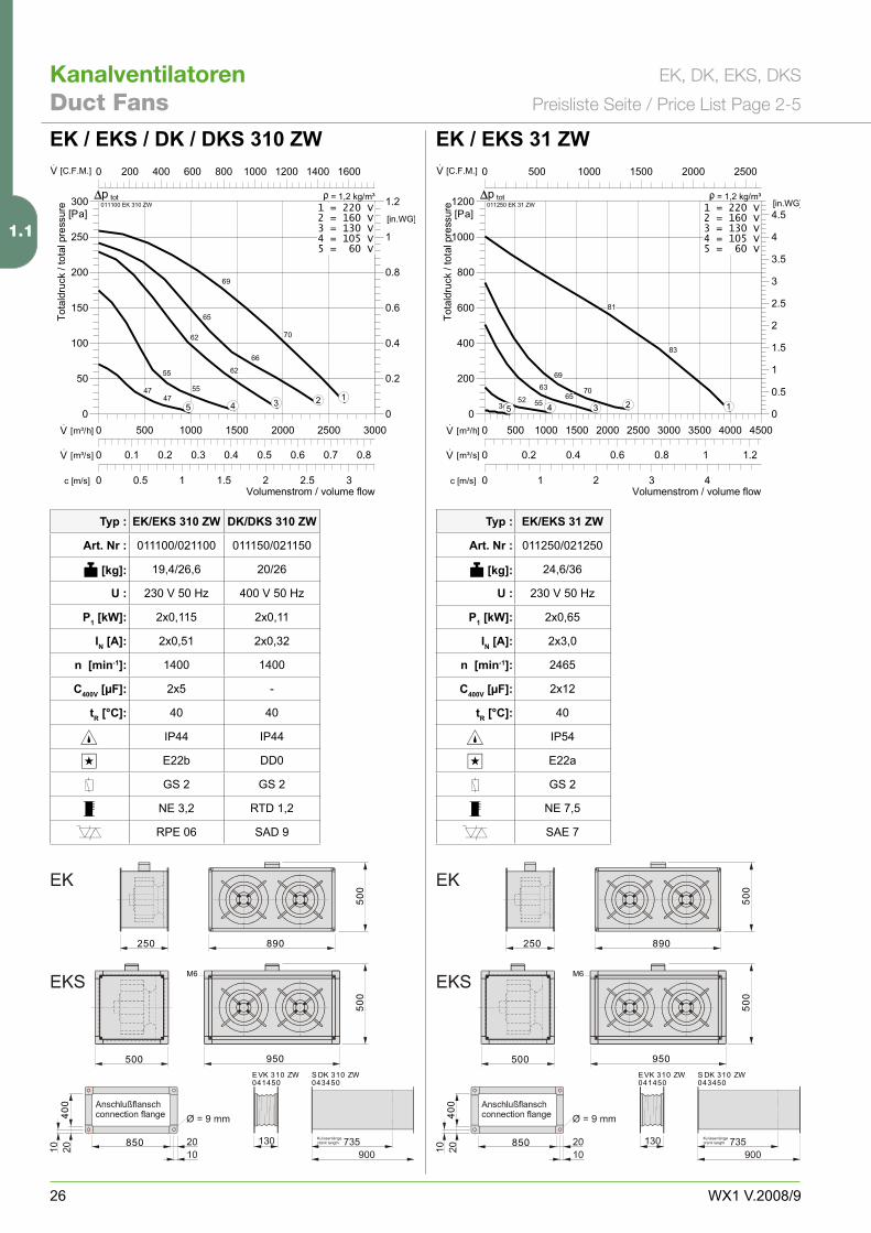
0 1 2 3 4c [m/s]
0 500 1000 1500 2000 2500·V [C.F.M.]
0 0.2 0.4 0.6 0.8 1 1.2·V [m³/s]
0 500 1000 1500 2000 2500 3000 3500 4000 4500·V [m³/h]0
0.5
1
1.5
2
2.5
3
3.5
4
4.5[in.WG]
0
200
400
600
800
1000
1200[Pa]
Volumenstrom / volume flow
Totaldruck/totalpressure 011250 EK 31 ZW
totp = 1,2 kg/m³1 = 220 V2 = 160 V3 = 130 V4 = 105 V5 = 60 V
81
83
69
70636552 553434 12345
0 0.5 1 1.5 2 2.5 3c [m/s]
0 200 400 600 800 1000 1200 1400 1600·V [C.F.M.]
0 0.1 0.2 0.3 0.4 0.5 0.6 0.7 0.8·V [m³/s]
0 500 1000 1500 2000 2500 3000·V [m³/h]
0
0.2
0.4
0.6
0.8
1
1.2[in.WG]
0
50
100
150
200
250
300[Pa]
Volumenstrom / volume flow
Totaldruck
/totalpressure 011100 EK 310 ZW
totp = 1,2 kg/m³1 = 220 V2 = 160 V3 = 130 V4 = 105 V5 = 60 V
69
70
65
66
62
6255
554747 12345
EK / EKS / DK / DKS 310 ZW
EK/EKS 310 ZW
011100/0�1100
19,�/�6,6
��0 V 50 Hz
�x0,115
�x0,51
1�00
�x5
�0
IP��
E��b
GS �
NE �,�
RPE 06
DK/DKS 310 ZW
011150/0�1150
�0/�6
�00 V 50 Hz
�x0,11
�x0,��
1�00
-
�0
IP��
DD0
GS �
RTD 1,�
SAD 9
EK / EKS 31 ZW
EK/EKS 31 ZW
011�50/0�1�50
��,6/�6
��0 V 50 Hz
�x0,65
�x�,0
��65
�x1�
�0
IP5�
E��a
GS �
NE 7,5
SAE 7
1.1
�7WX1 V.�008/9
!"EKS, DKS EK, DK
Typ :
Art. Nr :
) [kg]:
U :
P1 [kW]:
IN [A]:
n [min-1]:
C400V [µF]:
tR [°C]:
45-,*
Typ :
Art. Nr :
) [kg]:
U :
P1 [kW]:
IN [A]:
n [min-1]:
C400V [µF]:
tR [°C]:
45-,*
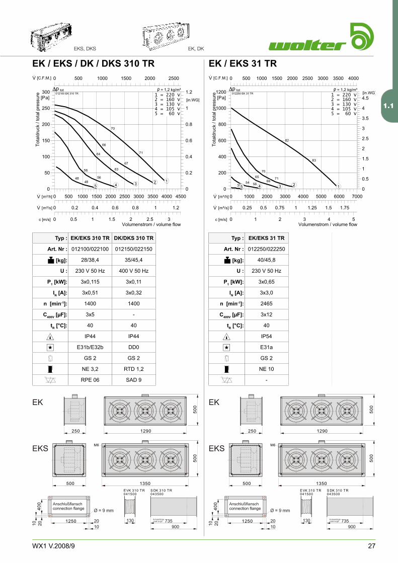
EK / EKS / DK / DKS 310 TR
EK/EKS 310 TR
01�100/0��100
�8/�8,�
��0 V 50 Hz
�x0,115
�x0,51
1�00
�x5
�0
IP��
E�1b/E��b
GS �
NE �,�
RPE 06
EK / EKS 31 TR
EK/EKS 31 TR
01��50/0���50
�0/�5,8
��0 V 50 Hz
�x0,65
�x�,0
��65
�x1�
�0
IP5�
E�1a
GS �
NE 10
-
250 1290
1250
40
0
50
0
500 1350
50
0
E VK 310 T R S DK 310 T R041500 043500
0 0.5 1 1.5 2 2.5 3c [m/s]
0 500 1000 1500 2000 2500·V [C.F.M.]
0 0.2 0.4 0.6 0.8 1 1.2·V [m³/s]
0 500 1000 1500 2000 2500 3000 3500 4000 4500·V [m³/h]0
0.2
0.4
0.6
0.8
1
1.2[in.WG]
0
50
100
150
200
250
300[Pa]
Volumenstrom / volume flow
Totaldruck/totalpressure 012100 EK 310 TR
totp = 1,2 kg/m³1 = 220 V2 = 160 V3 = 130 V4 = 105 V5 = 60 V
70
71
66
67
64
6356
564848 12345
0 1 2 3 4 5c [m/s]
0 500 1000 1500 2000 2500 3000 3500 4000·V [C.F.M.]
0 0.25 0.5 0.75 1 1.25 1.5 1.75·V [m³/s]
0 1000 2000 3000 4000 5000 6000 7000·V [m³/h]0
0.5
1
1.5
2
2.5
3
3.5
4
4.5[in.WG]
0
200
400
600
800
1000
1200[Pa]
Volumenstrom / volume flow
Totaldruck/totalpressure 012250 EK 31 TR
totp = 1,2 kg/m³1 = 220 V2 = 160 V3 = 130 V4 = 105 V5 = 60 V
82
83
70
71656654 563536 12345
250 1290
1250
40
0
50
0
500 1350
50
0
E VK 310 T R S DK 310 T R041500 043500
DK/DKS 310 TR
01�150/0��150
�5/�5,�
�00 V 50 Hz
�x0,11
�x0,��
1�00
-
�0
IP��
DD0
GS �
RTD 1,�
SAD 9
1.1


![-. @f ]dk Yf](https://img.pdfslide.org/doc/110x75/5b077e5b7f8b9a5c308e6ddb/-f-dk-yf-m-mkl-zd-ciml250xcomciml250xcomarchivemarxengelsgermanengelsbriefeanaugustaj.jpg)