Embed Size (px)
Citation preview
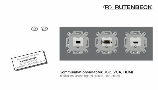
Kommunikationsadapter USB, VGA, HDMIInstallationsanleitung/Installation Instructions
Bei Installationsfragen
Kundenservice:
(03 69 25) 9 00 90
2
Sicherheitshinweise ................................... 3Bedienung .................................................. 3Multimediageräte anschließen ......................... 4Für Elektrofachkräfte .................................. 4Multimedia-Steckdose montieren .................... 4USB-Anschluss .......................................... 5Kabelinstallation ............................................ 5Belegung ...................................................... 7VGA-Anschluss .......................................... 8Kabelinstallation ............................................ 8Belegung .................................................... 10
Inhaltsverzeichnis
HDMI-Anschluss ...................................... 11Kabelinstallation .......................................... 13Belegung .................................................... 15Hilfe bei Funktionsstörungen .................. 17Technische Daten .................................... 18Garantie .................................................... 18Instandsetzung ............................................ 18Herstellererklärung .................................. 19Entsorgung ............................................... 19
3
Einbau und Montage elektri-scher Geräte dürfen nur durch Elektrofachkräfte erfolgen. Dabei sind die geltenden Unfallverhütungsvorschriften zu beachten.Bei Nichtbeachtung der Anleitung können Schäden am Gerät, Brand oder andere Gefahren entstehen.Eine einwandfreie Signal-übertragung ist nur bei Ver-wendung von passendem Zubehör sowie der Einhaltung der spezifizierten maximalen Leitungslängen und des mini-mal zulässigen Abstands zu stromführenden Leitungen und
Störquellen (z. B. EVGs, Dim-mer, ESL) gewährleistet.Die Kabelschirme sind gemäß den Vorgaben beizubehalten bzw. anzuschließen.Diese Bedienungsanleitung ist Bestandteil des Produkts und muss beim Endanwender verbleiben.
Nur zugelassene An-schlussleitungen und -stecker verwenden!
Die Verwendung nicht genormten Zubehörs kann zu Fehlfunktionen der Geräte füh-ren oder sie zerstören.
Sicherheitshinweise Bedienung
4
Für die Installation wird eine Einbaudose in der Wand mon-tiert (Empfehlung: Kaiser „Elec-tronic-Dose“, Art. Nr. 1068-02 oder 9062-74 zur Einhaltung der zulässigen Biegeradien verwenden).Nach der Kabelinstallation kann der Kommunikationsad-apter in Betrieb genommen werden. Schalten Sie die
Ge räte vor dem Anschließen aus!
Der Anschluss eingeschalteter Geräte kann zu Kurzschluss führen und die Geräte zer-stören!
· Stecker der Verbindungslei-tung von der Signalquelle, wie z. B. DVD- oder MP3-Player, in die Buchse des Kommunikationsadapters stecken.
· Stecker der Verbindungslei-tung vom Wiedergabegerät, wie z. B. LCD-/Plasma-Fern-seher oder Musikanlage, in die Buchse eines zweiten Kommunikations-adapters stecken.
· Stecker gerade und mit geringem Kraftaufwand in die Buchsen stecken, damit sich die Kontakte nicht beim
Verdrehen oder Verkanten der Stecker verbiegen.
Für ElektrofachkräfteMultimedia-Steckdose montieren
BedienungMultimediageräte anschließen
5
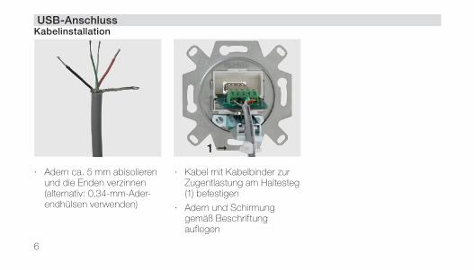
USB-AnschlussKabelinstallation
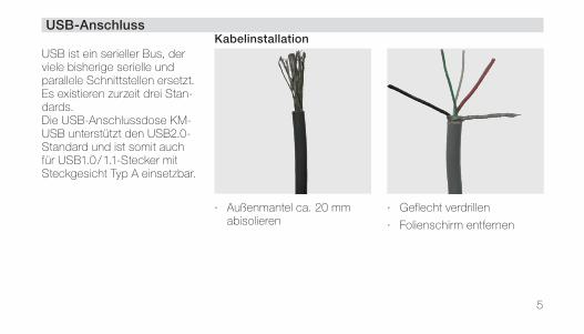
USB ist ein serieller Bus, der viele bisherige serielle und parallele Schnittstellen ersetzt. Es existieren zurzeit drei Stan-dards.Die USB-Anschlussdose KM-USB unterstützt den USB2.0-Standard und ist somit auch für USB1.0 / 1.1-Stecker mit Steckgesicht Typ A einsetzbar.
· Außenmantel ca. 20 mm abisolieren
· Geflecht verdrillen
· Folienschirm entfernen
6
· Adern ca. 5 mm abisolieren und die Enden verzinnen (alternativ: 0,34-mm-Ader-endhülsen verwenden)
· Kabel mit Kabelbinder zur Zugentlastung am Haltesteg (1) befestigen
· Adern und Schirmung gemäß Beschriftung auflegen
USB-AnschlussKabelinstallation
1
7
Typ Klemmen-nummer
Klemmen-bezeichnung
PIN-Nr. der Buchse
Farbbeispiel für Kabelbelegung
Beschreibung
Stecker (von vorn)
1 2 3 4
Buchse (von vorn)
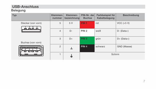
5 5 V PIN 1 rot VCC (+5 V)
4 D- PIN 2 weiß D- (Data–)
3 D+ PIN 3 grün D+ (Data+)
2 PIN 4 schwarz GND (Masse)
1 Schirm
USB-AnschlussBelegung
4 3 2 1
8
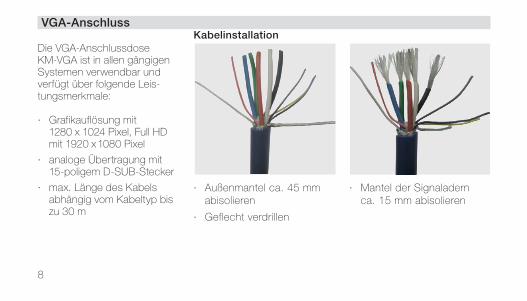
VGA-AnschlussKabelinstallation
Die VGA-Anschlussdose KM-VGA ist in allen gängigen Systemen verwendbar und verfügt über folgende Leis-tungsmerkmale:
· Grafikauflösung mit 1280 x 1024 Pixel, Full HD mit 1920 x 1080 Pixel
· analoge Übertragung mit 15-poligem D-SUB-Stecker
· max. Länge des Kabels abhängig vom Kabeltyp bis zu 30 m
· Außenmantel ca. 45 mm abisolieren
· Geflecht verdrillen
· Mantel der Signaladern ca. 15 mm abisolieren
9
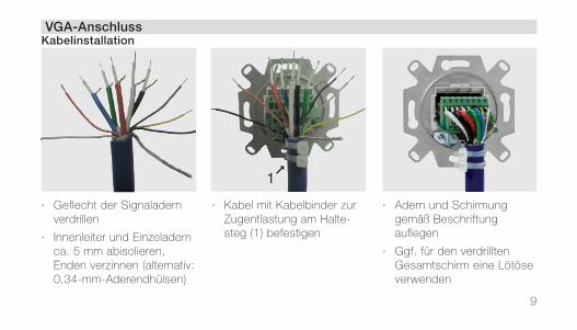
VGA-AnschlussKabelinstallation
· Geflecht der Signaladern verdrillen
· Innenleiter und Einzeladern ca. 5 mm abisolieren, Enden verzinnen (alternativ: 0,34-mm-Aderendhülsen)
· Kabel mit Kabelbinder zur Zugentlastung am Halte-steg (1) befestigen
· Adern und Schirmung gemäß Beschriftung auflegen
· Ggf. für den verdrillten Gesamtschirm eine Lötöse verwenden
1
10
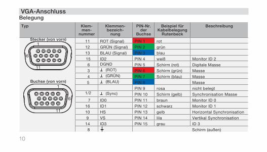
VGA-AnschlussBelegung
Typ Klem-men-
nummer
Klemmen-bezeich-
nung
PIN-Nr. der
Buchse
Beispiel für Kabelbelegung
Rutenbeck
Beschreibung
Stecker (von vorn) 1
6
11
Buchse (von vorn)1
6
11
11 ROT (Signal) PIN 1 rot
12 GRÜN (Signal) PIN 2 grün
13 BLAU (Signal) PIN 3 blau
15 ID2 PIN 4 weiß Monitor ID 2
6 DGND PIN 5 Schirm (rot) Digitale Masse
3 (ROT) PIN 6 Schirm (grün) Masse
4 (GRÜN) PIN 7 Schirm (blau) Masse
5 (BLAU) PIN 8 Masse
PIN 9 rosa nicht belegt 1/2 (Sync) PIN 10 Schirm (gelb) Synchronisation Masse
7 ID0 PIN 11 braun Monitor ID 0
16 ID1 PIN 12 schwarz Monitor ID 1
10 HS PIN 13 gelb Horizontal Synchronisation
9 VS PIN 14 lila Vertikal Synchronisation
14 ID3 PIN 15 grau ID 3
8 Schirm (außen)
11
HDMI-Anschluss
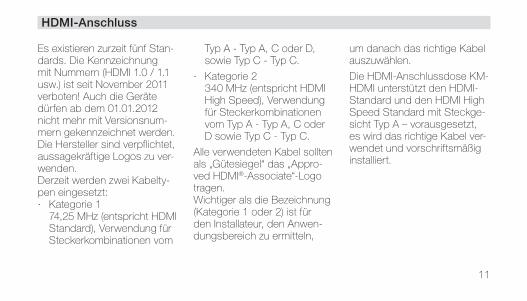
Es existieren zurzeit fünf Stan-dards. Die Kennzeichnung mit Nummern (HDMI 1.0 / 1.1 usw.) ist seit November 2011 verboten! Auch die Geräte dürfen ab dem 01.01.2012 nicht mehr mit Versionsnum-mern gekennzeichnet werden. Die Hersteller sind verpflichtet, aussagekräftige Logos zu ver-wenden.Derzeit werden zwei Kabelty-pen eingesetzt: · Kategorie 1
74,25 MHz (entspricht HDMI Standard), Verwendung für Steckerkombinationen vom
Typ A - Typ A, C oder D, sowie Typ C - Typ C.
· Kategorie 2 340 MHz (entspricht HDMI High Speed), Verwendung für Steckerkombinationen vom Typ A - Typ A, C oder D sowie Typ C - Typ C.
Alle verwendeten Kabel sollten als „Gütesiegel“ das „Appro-ved HDMI®-Associate“-Logo tragen.Wichtiger als die Bezeichnung (Kategorie 1 oder 2) ist für den Installateur, den Anwen-dungsbereich zu ermitteln,
um danach das richtige Kabel auszuwählen.
Die HDMI-Anschlussdose KM-HDMI unterstützt den HDMI-Standard und den HDMI High Speed Standard mit Steckge-sicht Typ A – vorausgesetzt, es wird das richtige Kabel ver-wendet und vorschriftsmäßig installiert.
12
HDMI-Anschluss
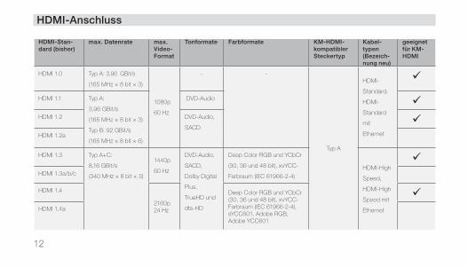
HDMI-Stan-dard (bisher)
max. Datenrate max.Video-Format
Tonformate Farbformate KM-HDMI-kompatibler Steckertyp
Kabel-typen (Bezeich-nung neu)
geeignet für KM-HDMI
HDMI 1.0 Typ A: 3,96 GBit/s
(165 MHz × 8 bit × 3)
1080p
60 Hz
- -
Typ A
HDMI-
Standard,
HDMI-
Standard
mit
Ethernet
HDMI 1.1 Typ A:
3,96 GBit/s
(165 MHz × 8 bit × 3)
Typ B: 92 GBit/s
(165 MHz × 8 bit × 6)
DVD-Audio HDMI 1.2 DVD-Audio,
SACD
HDMI 1.2a
HDMI 1.3 Typ A+C:
8,16 GBit/s
(340 MHz × 8 bit × 3)
1440p
60 Hz
DVD-Audio,
SACD,
Dolby Digital
Plus,
TrueHD und
dts-HD
Deep Color RGB und YCbCr
(30, 36 und 48 bit), xvYCC-
Farbraum (IEC 61966-2-4)
HDMI-High
Speed,
HDMI-High
Speed mit
Ethernet
HDMI 1.3a/b/c
HDMI 1.4
2160p24 Hz
Deep Color RGB und YCbCr (30, 36 und 48 bit), xvYCC-Farbraum (IEC 61966-2-4), sYCC601, Adobe RGB, Adobe YCC601
HDMI 1.4a
13
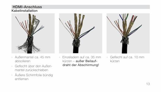
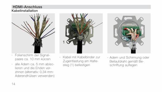
HDMI-AnschlussKabelinstallation
· Außenmantel ca. 45 mm abisolieren
· Geflecht über den Außen-mantel zurückschieben
· Äußere Schirmfolie bündig entfernen
· Einzeladern auf ca. 35 mm kürzen – außer Beilauf-draht der Abschirmung!
· Geflecht auf ca. 10 mm kürzen
14
HDMI-AnschlussKabelinstallation
· Folienschirm der Signal-paare ca. 10 mm kürzen
· alle Adern ca. 5 mm ab iso- lieren und die Enden ver - zinnen (alternativ: 0,34-mm- Aderendhülsen verwenden)
· Kabel mit Kabelbinder zur Zugentlastung am Halte-steg (1) befestigen
· Adern und Schirmung oder Beilaufdraht gemäß Be-schriftung auflegen
1
15
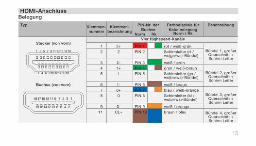
Typ Klemmen-nummer
Klemmen-bezeichnung
PIN-Nr. der Buchse
Norm Rk
Farbbeispiele für Kabelbelegung
Norm / Rk
Beschreibung
Stecker (von vorn)
Buchse (von vorn)
Vier Highspeed-Kanäle
1 2+ PIN 1 rot / weiß-grünBündel 1, großer
Querschnitt + Schirm Leiter
2 2 PIN 2 Schirmleiter (rt /ws(gn/ws)-Bündel)
3 2- PIN 3 weiß / grün 4 1+ PIN 4 grün / weiß-braun
Bündel 2, großer Querschnitt + Schirm Leiter
5 1 PIN 5 Schirmleiter (gn /ws(bn/ws)-Bündel)
6 1- PIN 6 weiß / braun 7 0+ PIN 7 blau / weiß-orange
Bündel 3, großer Querschnitt + Schirm Leiter
8 0 PIN 8 Schirmleiter (bl /ws(or/ws)-Bündel)
9 0- PIN 9 weiß / orange11 CL+ PIN 10 braun / blau Bündel 4, großer
Querschnitt + Schirm Leiter
HDMI-AnschlussBelegung
16
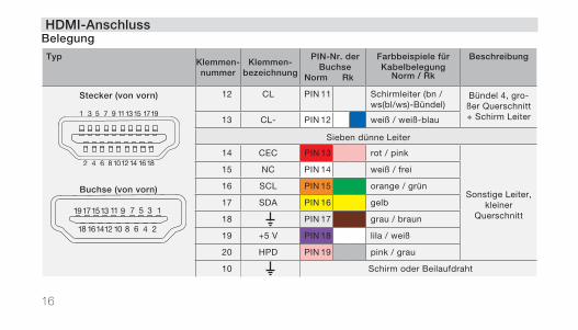
TypKlemmen-nummer
Klemmen-bezeichnung
PIN-Nr. der Buchse
Norm Rk
Farbbeispiele für Kabelbelegung
Norm / Rk
Beschreibung
Stecker (von vorn)
Buchse (von vorn)
12 CL PIN 11 Schirmleiter (bn /ws(bl/ws)-Bündel)
Bündel 4, gro-ßer Querschnitt + Schirm Leiter13 CL- PIN 12 weiß / weiß-blau
Sieben dünne Leiter
14 CEC PIN 13 rot / pink
Sonstige Leiter, kleiner
Querschnitt
15 NC PIN 14 weiß / frei
16 SCL PIN 15 orange / grün
17 SDA PIN 16 gelb
18 PIN 17 grau / braun
19 +5 V PIN 18 lila / weiß
20 HPD PIN 19 pink / grau
10 Schirm oder Beilaufdraht
HDMI-AnschlussBelegung
17
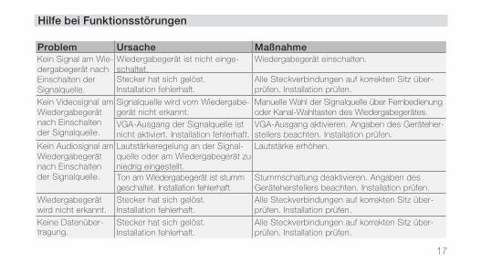
Problem Ursache MaßnahmeKein Signal am Wie-dergabegerät nach Einschalten der Signalquelle.
Wiedergabegerät ist nicht einge-schaltet.
Wiedergabegerät einschalten.
Stecker hat sich gelöst.Installation fehlerhaft.
Alle Steckverbindungen auf korrekten Sitz über-prüfen. Installation prüfen.
Kein Videosignal am Wiedergabegerät nach Einschalten der Signalquelle.
Signalquelle wird vom Wiedergabe-gerät nicht erkannt.
Manuelle Wahl der Signalquelle über Fernbedienung oder Kanal-Wahltasten des Wiedergabegerätes.
VGA-Ausgang der Signalquelle ist nicht aktiviert. Installation fehlerhaft.
VGA-Ausgang aktivieren. Angaben des Geräteher-stellers beachten. Installation prüfen.
Kein Audiosignal am Wiedergabegerät nach Einschalten der Signalquelle.
Lautstärkeregelung an der Signal-quelle oder am Wiedergabegerät zu niedrig eingestellt.
Lautstärke erhöhen.
Ton am Wiedergabegerät ist stumm geschaltet. Installation fehlerhaft.
Stummschaltung deaktivieren. Angaben des Geräteherstellers beachten. Installation prüfen.
Wiedergabegerät wird nicht erkannt.
Stecker hat sich gelöst.Installation fehlerhaft.
Alle Steckverbindungen auf korrekten Sitz über-prüfen. Installation prüfen.
Keine Datenüber-tragung.
Stecker hat sich gelöst.Installation fehlerhaft.
Alle Steckverbindungen auf korrekten Sitz über-prüfen. Installation prüfen.
Hilfe bei Funktionsstörungen
18
Die technischen Daten finden Sie in den aktuellen Daten-blättern unter der entspre-chenden Artikelnummer im Produktbereich unter www.rutenbeck.de.
Im Falle einer Reklamation oder einer nicht behebbaren Funktionsstörung wenden Sie sich bitte an Ihren Fach-händler oder senden Sie das Gerät mit Kaufbeleg und einer kurzen Fehlerbeschreibung an nachstehende Anschrift:
Rutenbeck KundenserviceGewerbegebietIm Meilesfeld 599819 Marksuhl
Telefon (03 69 25) 9 00 90Telefax (03 69 25) 9 00 92
Wir garantieren für 2 Jahre nach Kaufdatum (Quittungs-beleg) bei sachgemäßer Installation und Behandlung die einwandfreie Funktion des Gerätes.Bei telefonischen Rückfragen wenden Sie sich bitte an die Rutenbeck-Kundenservice:+49 - (0)3 69 25 - 9 00 90
GarantieInstandsetzung
Technische Daten
19
Wir, die Wilhelm Rutenbeck GmbH & Co. KG, erklären in alleiniger Verantwortung, dass sich die Kommunikations-adap ter KM-USB, KM-VGA und KM-HDMI in Übereinstim-mung mit den Anforderungen und Vorschriften der Richtlinie
- 2011/65/EU (RoHS-Richtlinie) befinden.
Die vollständige Konformitäts-erklärung finden Sie unter www.rutenbeck.de im Down-load-Bereich.
Herstellererklärung
Bitte leisten Sie Ihren Beitrag zur Entlastung der Umwelt, indem Sie dieses Gerät nach Ende seiner Nutzung einer umweltgerechten Verwertung zuführen. Auf keinen Fall sollten Sie das Gerät in den unsortierten Siedlungsmüll geben.Bei unsachgemässer Beseiti-gung von Elektroschrott könn-ten gefährliche Stoffe unsere Umwelt und unser aller Ge-sundheit beeinträchtigen.
Entsorgung

20
21
Table of Contents
Safety Instructions .................................. 21Operation ................................................. 21For Electrically Qualified Persons ......... 22Mount the multimedia outlet ........................ 22Connecting multimedia devices .................. 22USB-Connection ..................................... 23Cable Installation ........................................ 23Assignment ................................................ 25VGA-Connection ..................................... 26Cable Installation ........................................ 26Assignment ................................................ 28
HDMI-Connection ................................... 29Cable Installation ........................................ 31Assignment ................................................ 33Trouble Shooting ..................................... 35Technical Data ......................................... 36Guarantee ................................................ 36Service ...................................................... 36Manufacturer‘s Declaration ................... 37Disposal ................................................... 37
22
The installation and assembly of electrical devices may only be performed by professional electricians. The applicable accident prevention regula-tions must be followed during installation and assembly. Ignoring or not following these instructions can result in dam-age to the device, fires, or other hazards. The cable shields are to be retained and connected according to the specifica-tions. These operating instructions are an integral part of the
product and must be provided to the end user. Faultless signal transmission is only guaranteed when the appropriate accessories are used and when the specified maximum cable lengths and the minimal permissible dis-tance to electrical cables and sources of interference (such as electronic ballasts, dim-mers, ESLs) are maintained.
Use only authorized connecting cables and connectors!
The use of non-standardized accessories can lead to the malfunction or destruction of the device.
Safety Instructions Operation
23
A wall box is mounted in the wall for installation purpos-es (recommended: use the Kaiser “Electronics Box”, Art. No. 1068-02 or 9062-74, to ensure the permissible bend-ing radius is not exceeded). After the cables are installed, the communications adapter can be put into operation. Switch off the devices
before making the connections!
Connecting devices that are switched on can result in short circuits and destroy the devices!
· Plug the connection cable from the signal source, for example a DVD or MP3 player, into the outlet of the communications adapter.
· Plug the connection cable of the playback device such as an LCD or plasma televi-sion or a stereo system into the outlet of a second com-munications adapter.
· Plug the cables in straight into the outlets without apply too much force so that the contacts do not bend if the plug is inserted incorrectly or at an angle.
For Electrically Qualified PersonsMount the multimedia outlet Connecting multim. devices
Operation
24
USB-ConnectionCable Installation
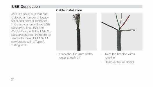
USB is a serial bus that has replaced a number of legacy serial and parallel interfaces. There are currently three USB standards. The USB port KM USB supports the USB 2.0 standard and can therefore be used with male USB 1.0 / 1.1 connectors with a Type A mating face.
· Strip about 20 mm of the outer sheath off
· Twist the braided wires together
· Remove the foil shield
25
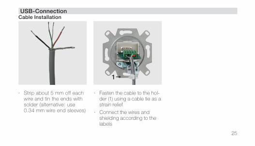
· Strip about 5 mm off each wire and tin the ends with solder (alternative: use 0.34 mm wire end sleeves)
· Fasten the cable to the hol-der (1) using a cable tie as a strain relief
· Connect the wires and shielding according to the labels
USB-ConnectionCable Installation
1

26
USB-ConnectionAssignmentType Terminal
numberTerminal
designationPIN-no. of
the jackExample of color
code for cable assignment
Description
plug (from the front)
1 2 3 4
jack (from the front)
4 3 2 1
5 5 V PIN 1 red VCC (+5 V)
4 D- PIN 2 white D- (Data–)
3 D+ PIN 3 green D+ (Data+)
2 PIN 4 black GND (ground)
1 Shielding
27
VGA-ConnectionCable Installation
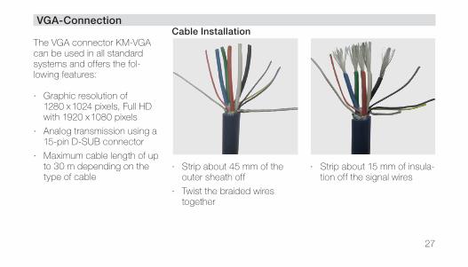
The VGA connector KM-VGA can be used in all standard systems and offers the fol-lowing features:
· Graphic resolution of 1280 x 1024 pixels, Full HD with 1920 x 1080 pixels
· Analog transmission using a 15-pin D-SUB connector
· Maximum cable length of up to 30 m depending on the type of cable
· Strip about 45 mm of the outer sheath off
· Twist the braided wires together
· Strip about 15 mm of insula-tion off the signal wires
28
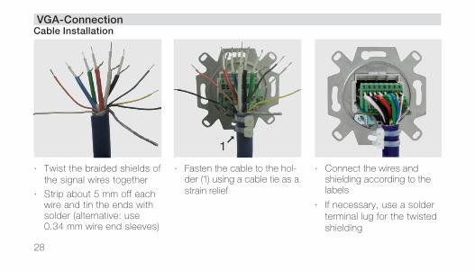
VGA-ConnectionCable Installation
· Twist the braided shields of the signal wires together
· Strip about 5 mm off each wire and tin the ends with solder (alternative: use 0.34 mm wire end sleeves)
· Fasten the cable to the hol-der (1) using a cable tie as a strain relief
· Connect the wires and shielding according to the labels
· If necessary, use a solder terminal lug for the twisted shielding
1
29
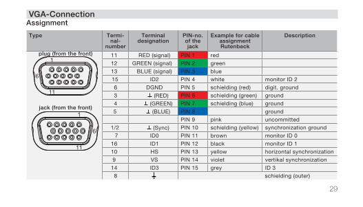
VGA-ConnectionAssignment
Type Termi-nal-
number
Terminal designation
PIN-no. of the jack
Example for cable assignmentRutenbeck
Description
plug (from the front) 1
6
11
jack (from the front) 1
6
11
11 RED (signal) PIN 1 red
12 GREEN (signal) PIN 2 green
13 BLUE (signal) PIN 3 blue
15 ID2 PIN 4 white monitor ID 2
6 DGND PIN 5 schielding (red) digit. ground
3 (RED) PIN 6 schielding (green) ground
4 (GREEN) PIN 7 schielding (blue) ground
5 (BLUE) PIN 8 ground
PIN 9 pink uncommitted
1/2 (Sync) PIN 10 schielding (yellow) synchronization ground
7 ID0 PIN 11 brown monitor ID 0
16 ID1 PIN 12 black monitor ID 1
10 HS PIN 13 yellow horizontal synchronization
9 VS PIN 14 violet vertikal synchronization
14 ID3 PIN 15 grey ID 3
8 schielding (outer)
30
HDMI-Connection
There are currently five stand-ards. Using numbers to des-ignate the version (HDMI 1.0 / 1.1, etc.) is prohibited since November 2011! Devices are not permitted to display ver-sion numbers any more either since January 1, 2012. The manufacturers are required to use descriptive logos. Two types of cable are currently in use: · Category 1
74.25 MHz (corresponding to the HDMI Standard), can be used for Type A - Type A, C, or D as well as
Type C - Type C connector combinations.
· Category 2 340 MHz (corresponding to HDMI High Speed), can be used for Type A - Type A, C, or D as well as for Type C - Type C connector combinations.
All cables used should bear the “Approved HDMI®-Associ-ate” logo as a seal of approval. It is more important for the installer to determine the type of application than the desig-nation (Category 1 or 2) so that the correct cable can then be
selected. The HDMI connector KM HDMI supports the HDMI standard and the HDMI High Speed standard with Type A connectors – assuming the correct cable is used and has been properly installed.
31
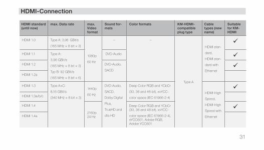
HDMI-Connection
HDMI standard (until now)
max. Data rate max.Video format
Sound for-mats
Color formats KM-HDMI-compatible plug type
Cable types (new name)
Suitable for KM-HDMI
HDMI 1.0 Type A: 3,96 GBit/s
(165 MHz × 8 bit × 3)
1080p
60 Hz
– –
Type A
HDMI stan-
dard,
HDMI stan-
dard with
Ethernet
HDMI 1.1 Type A:
3,96 GBit/s
(165 MHz × 8 bit × 3)
Typ B: 92 GBit/s
(165 MHz × 8 bit × 6)
DVD-Audio HDMI 1.2 DVD-Audio,
SACD
HDMI 1.2a
HDMI 1.3 Type A+C:
8,16 GBit/s
(340 MHz × 8 bit × 3)
1440p
60 Hz
DVD-Audio,
SACD,
Dolby Digital
Plus,
TrueHD and
dts-HD
Deep Color RGB and YCbCr
(30, 36 and 48 bit), xvYCC-
color space (IEC 61966-2-4)
HDMI-High
Speed,
HDMI-High
Speed with
Ethernet
HDMI 1.3a/b/c
HDMI 1.4
2160p24 Hz
Deep Color RGB and YCbCr (30, 36 and 48 bit), xvYCC-
color space (IEC 61966-2-4), sYCC601, Adobe RGB, Adobe YCC601
HDMI 1.4a
32
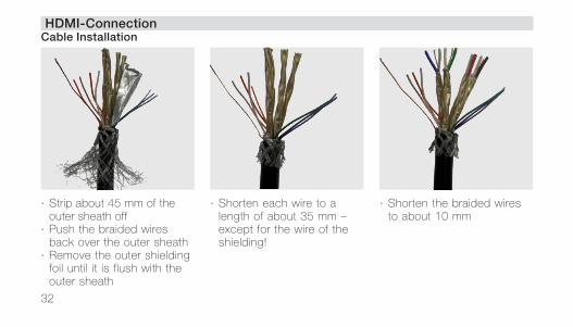
HDMI-ConnectionCable Installation
· Strip about 45 mm of the outer sheath off
· Push the braided wires back over the outer sheath
· Remove the outer shielding foil until it is flush with the outer sheath
· Shorten each wire to a length of about 35 mm – except for the wire of the shielding!
· Shorten the braided wires to about 10 mm
33
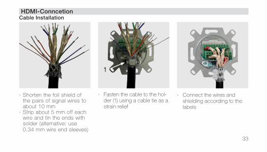
HDMI-ConncetionCable Installation
· Shorten the foil shield of the pairs of signal wires to about 10 mm
· Strip about 5 mm off each wire and tin the ends with solder (alternative: use 0.34 mm wire end sleeves)
· Fasten the cable to the hol-der (1) using a cable tie as a strain relief
· Connect the wires and shielding according to the labels
1
34
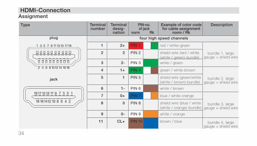
HDMI-ConnectionAssignment
Type Terminal number
Terminal desig-nation
PIN-no. of jack
norm Rk
Example of color code for cable assignment
norm / Rk
Description
plug
jack
four high speed channels
1 2+ PIN 1 red / white-green
bundle 1, large gauge + shield wire
2 2 PIN 2 shield wire (red / white (white / green)-bundle)
3 2- PIN 3 white / green
4 1+ PIN 4 green / white-brown
bundle 2, large gauge + shield wire
5 1 PIN 5 shield wire (green/white (white / brown)-bundle)
6 1- PIN 6 white / brown
7 0+ PIN 7 blue / white-orange
bundle 3, large gauge + shield wire
8 0 PIN 8 shield wire (blue / white (white / orange)-bundle)
9 0- PIN 9 white / orange
11 CL+ PIN 10 brown / blue bundle 4, large gauge + shield wire
35
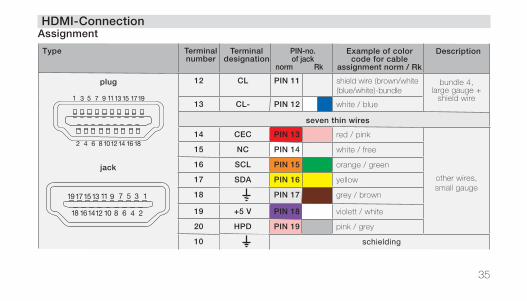
HDMI-ConnectionAssignment
Type Terminal number
Terminal designation
PIN-no. of jack
norm Rk
Example of color code for cable
assignment norm / Rk
Description
plug
jack
12 CL PIN 11 shield wire (brown/white (blue/white)-bundle
bundle 4, large gauge +
shield wire13 CL- PIN 12 white / blue
seven thin wires
14 CEC PIN 13 red / pink
other wires, small gauge
15 NC PIN 14 white / free
16 SCL PIN 15 orange / green
17 SDA PIN 16 yellow
18 PIN 17 grey / brown
19 +5 V PIN 18 violett / white
20 HPD PIN 19 pink / grey
10 schielding
36
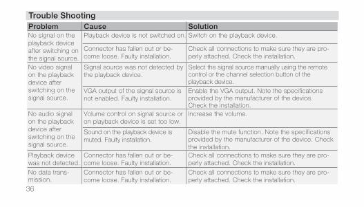
Trouble ShootingProblem Cause SolutionNo signal on the playback device after switching on the signal source.
Playback device is not switched on. Switch on the playback device.
Connector has fallen out or be-come loose. Faulty installation.
Check all connections to make sure they are pro-perly attached. Check the installation.
No video signal on the playback device after switching on the signal source.
Signal source was not detected by the playback device.
Select the signal source manually using the remote control or the channel selection button of the playback device.
VGA output of the signal source is not enabled. Faulty installation.
Enable the VGA output. Note the specifications provided by the manufacturer of the device. Check the installation.
No audio signal on the playback device after switching on the signal source.
Volume control on signal source or on playback device is set too low.
Increase the volume.
Sound on the playback device is muted. Faulty installation.
Disable the mute function. Note the specifications provided by the manufacturer of the device. Check the installation.
Playback device was not detected.
Connector has fallen out or be-come loose. Faulty installation.
Check all connections to make sure they are pro-perly attached. Check the installation.
No data trans-mission.
Connector has fallen out or be-come loose. Faulty installation.
Check all connections to make sure they are pro-perly attached. Check the installation.
37
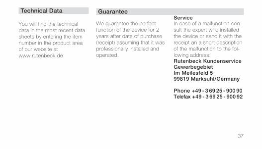
You will find the technical data in the most recent data sheets by entering the item number in the product area of our website at www.rutenbeck.de
In case of a malfunction con-sult the expert who installed the device or send it with the receipt an a short description of the malfunction to the fol-lowing address:Rutenbeck KundenserviceGewerbegebietIm Meilesfeld 599819 Marksuhl/Germany
Phone +49 - 3 69 25 - 900 90Telefax +49 - 3 69 25 - 900 92
We guarantee the perfect function of the device for 2 years after date of purchase (receipt) assuming that it was professionally installed and operated.
Technical Data GuaranteeService
38
We, Wilhelm Rutenbeck GmbH & Co. KG, declare under our sole responsibility that the “Kommunikations-adapters USB, VGA, HDMI” were manufactured in con-formity with the following re- quirements and regulations of
- 2011/65/EU (RoHS Directive)
The complete Declaration of Conformity is available in the Download Section at www.rutenbeck.de
Manufact. Declaration
Please take part in protecting our environment by properly recycling this device at end of lifetime. You should never dispose this device in the regular garbage.Improper disposal of electro-nic waste can release dan-gerous substances into the environment and affect public health.
Disposal

39
© W
ilhel
m R
uten
beck
Gm
bH &
Co.
KG
·
29
3 6
73
· S
tand
/Sta
us 0
8.1
6
Tec
hnis
che
Änd
erun
gen
vorb
ehal
ten/
Sub
ject
ed t
o te
chni
cal c
hang
es
Klagebach 3358579 SchalksmühleTelefon +49 - (0) 23 55 - 82 - 0Telefax +49 - (0) 23 55 - 82 - 105