Embed Size (px)
Citation preview

Kurz�beschreibung
Brief description
CPX−SteuerblockPROFINET IOPC�WORX integriertTyp CPX−SF34Typ CPX−SF35
CPX Control BlockPROFINET IOPC�WORX integratedType CPX−SF34Type CPX−SF35
� Deutsch� English
748 1741007NH
CPX−Terminal

Festo CPX−SF34 1007NH 2
Deutsch 3 . . . . . . . . . . . . . . . . . . . . . . . . . . . . . . . . . . . . . . . . . . .
English 17 . . . . . . . . . . . . . . . . . . . . . . . . . . . . . . . . . . . . . . . . . . . .
TORX®, PHOENIX CONTACT®, PC WorX®, AUTOMATIONWORX®,Push−Pull® sind eingetragene Warenzeichen der jeweiligenHersteller in gewissen Ländern.
TORX®, PHOENIX CONTACT®, PC WorX®, AUTOMATIONWORX®,Push−Pull® are registered trademarks of their respective trademarkholders in certain countries.
Edition: 1007NHOriginal: de
© (Festo AG�&�Co., D�73726 Esslingen, Germany, 2010)Internet: �http://www.festo.comE−Mail: �[email protected]

Festo CPX−SF34 1007NH Deutsch 3
1 Benutzerhinweise
Der Steuerblock CPX−SF34/35 ist ausschließlich für dieSteuerung von pneumatischen und elektrischen Aktuato�ren, die Abfrage von Sensorsignalen durch E−Module undfür die Kommunikation über PROFINET IO bestimmt.
Hierbei sind die angegebenen Grenzwerte der technischenDaten einzuhalten. Ausführliche Informationen finden Siein der Beschreibung zu den Steuerblöcken CPX−SF34/35(P.BE−CPX−SF34−...) und der CPX−Systembeschreibung P.BE−CPX−SYS−... .
Warnung· Schalten Sie die Spannungsversorgung aus, bevorSie Module montieren oder demontieren bzw. Steck�verbinder zusammenstecken oder trennen (Gefahrvon Funktionsstörungen oder der Beschädigung).
· Verwenden Sie ausschließlich Stromquellen, die einesichere elektrische Trennung der Betriebsspannungnach IEC/DIN EN 60204−1 gewährleisten. Berücksich�tigen Sie zusätzlich die allgemeinen Anforderungenan PELV−Stromkreise gemäß IEC/DIN EN 60204−1.
· Schließen Sie einen Erdleiter mit ausreichendemLeitungsquerschnitt an den mit dem Erdungssymbolgekennzeichneten Anschluss des CPX−Terminals an.
· Der CPX−Steuerblock enthält elektrostatisch gefähr�dete Bauelemente. Berühren Sie deshalb keine Bauelemente. Beachten Sie die Handhabungsvor�schriften für elektrostatisch gefährdete Bauelemente.
HinweisNehmen Sie nur ein komplett montiertes undverdrahtetes CPX−Terminal in Betrieb.

Festo CPX−SF34 1007NH Deutsch4
2 Anschluss− und Anzeigeelemente
1
24
3
5
3
6
1 Netzwerksspezifische und CPX−/steuerungsspezifische LEDs
2 Speicherkarte
3 Netzwerkanschlüsse:SF34: 2 x Push−Pull RJ45, CuSF35: 2 x Push−Pull SCRJ, POF−LWL
4 DIL−Schalter
5 ungenutzt, immer mitAbdeckkappe versehen!
6 Typenschild mit MAC−ID
Netzwerkspezifische LEDs CPX−/steuerungsspez. LEDs
NF Netzwerkfehler: leuchtetrot wenn PROFINET−
PS Power System (grün) 1)
rot, wenn PROFINET−Verbindung gestört PL Power Load (grün) 1)
TP1 Link/Traffic Port 1, 2:� flackert grün bei Daten�
verkehr an TP1/TP2� ist aus bei Verbindung
SF Systemfehler: leuchtet rotbei Laufzeitfehler der SPSoder CPX−Peripheriefehler
TP2� ist aus bei Verbindung
zum PROFINET Controller (wenn NF LED aus)
M Motion/RUN (gelb):� blinkt: SPS auf STOP� leuchtet: SPS auf RUN
1) Detailinformationen: CPX−Systembeschreibung und Beschreibung P.BE−CPX−SF34−� (enthält SF35)

Festo CPX−SF34 1007NH Deutsch 5
3 Installationshinweise
3.1 Montage
Der Steuerblock ist in einen Verkettungsblock des CPX−Terminals montiert.
HinweisDer Steuerblock CPX−SF34/35 darf nur mit CPX−Metall−Verkettungsblöcken verwendet werden und muss daserste Modul im CPX−Terminal sein (von links gezählt).
WarnungSchalten Sie die Spannungsversorgung aus, bevor Sieden Steuerblock demontieren oder montieren (Gefahrvon Funktionsstörungen oder Beschädigung).
1 Schrauben, Anzugsdrehmoment 0,9 ... 1,1 Nm
2 CPX−Steuerblock
3 CPX−Metall−Verkettungsblock,hier: CPX−M−GE−EV−S−PP−5POL
3
1
2
1

Festo CPX−SF34 1007NH Deutsch6
Demontage:
· Schrauben herausdrehen und Steuerblock vorsichtigabheben.
Montage:
1. Dichtung und Dichtflächen prüfen und Anschlussblockwieder aufsetzen.
2. Schrauben von Hand über Kreuz anziehen. Anzugs�drehmoment 0,9 ... 1,1 Nm.
3.2 Einstellung der DIL−Schalter
1 DIL−Schalter 1:Boot−Einstellungender SPS
2 DIL−Schalter 2:reserviert
3 Speicherkarte (siehe Abschnitt 3.3)
1 2
3
Festo CPX−SF34 1007NH Deutsch 7
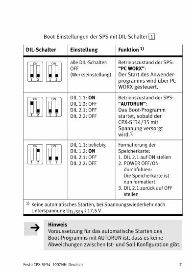
Boot−Einstellungen der SPS mit DIL−Schalter 1
DIL−Schalter Einstellung Funktion 1)
alle DIL−Schalter:OFF (Werkseinstellung)
Betriebszustand der SPS:�PC WORX":Der Start des Anwender�programms wird über PCWORX gesteuert.
DIL 1.1: ONDIL 1.2: OFFDIL 2.1: OFFDIL 2.2: OFF
Betriebszustand der SPS:�AUTORUN":Das Boot−Programmstartet, sobald derCPX−SF34/35 mit Spannung versorgtwird.1)
DIL 1.1: beliebigDIL 1.2: ONDIL 2.1: OFFDIL 2.2: OFF
Formatierung der Speicherkarte:1. DIL 2.1 auf ON stellen2. POWER OFF/ON
durchführen: Die Speicherkarte ist nun formatiert.
3. DIL 2.1 zurück auf OFFstellen
1) Keine automatisches Starten, bei Spannungswiederkehr nach Unterspannung UEL/SEN < 17,5�V
HinweisVoraussetzung für das automatische Starten des Boot−Programms mit AUTORUN ist, dass es keine Abweichungen zwischen Ist− und Soll−Konfiguration gibt.

Festo CPX−SF34 1007NH Deutsch8
3.3 Verwendung der Speicherkarte
Die Speicherkarte dient als Träger des Boot−Programmsfür�den Systemstart, der Anwenderprogramme und vonKonfigurationsdaten. Der PROFINET−IO−Gerätename istnicht auf der Speicherkarte des CPX−SF34/35 gespeichert.Detaillierte Informationen zur Verwendung: siehe Beschreibung P.BE−CPX−SF34−� (enthält SF35).
HinweisGefahr von Funktionsstörungen oder der Beschädigung
Entnehmen oder Einsetzen der Speicherkarte beieingeschalteter Spannungsversorgung kann zuFunktionsstörungen oder zur Beschädigung derSpeicherkarte führen.· Schalten Sie die Spannungsversorgung aus, bevor Siedie Speicherkarte entnehmen oder einsetzen.
Die Speicherkarte muss immer gesteckt sein, wennder CPX−SF34/35 gestartet wird!

Festo CPX−SF34 1007NH Deutsch 9
3.4 Netzwerk−Schnittstellen
Steuer�block
Anschlusstechnik Netzwerkstecker
CPX−SF34 2 x Push−Pull RJ45 Cu,AIDA−konform,entsprechendIEC�61076−3−117,IEC�61076−3−106,IEC�60603−7
Stecker von Festo, Typ FBS−RJ45−PP−GS für Ethernet−Leitungen mit Kabeldurchmesser5���8�mm (22 AWG)
CPX−SF35 2 x Push−Pull−Buchse,SCRJ, AIDA−konform
Stecker von Festo, Typ FBS−SCRJ−PP−GS für POF−Lichtwellenleiter entsprechend IEC�61754−24
Pinbelegung der Netzwerk−Schnittstelle des CPX−SF34:
RJ45−Buchse Pin Signal Erläuterung
12345678
8 1
12345678Gehäuse
TD+TD�RD+��RD���FE
Sendedaten+Sendedaten�Empfangsdaten+nicht angeschlossennicht angeschlossenEmpfangsdaten�nicht angeschlossennicht angeschlossenSchirm/Funktionserde
Festo CPX−SF34 1007NH Deutsch10
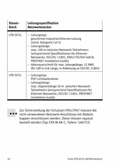
Steuer�block
LeitungsspezifikationNetzwerkstecker
CPX−SF34 � Leitungstyp:geschirmte Industrial−Ethernet−Leitung (mind. Kategorie Cat 5)
� Leitungslänge:max. 100�m zwischen Netzwerk−Teilnehmern (entsprechend Spezifikationen für Ethernet−Netzwerke, ISO/IEC 11801, ANSI/TIA/EIA−568−B,PROFINET Installation Guide)
� Adernquerschnitt für max. Leitungslänge: 22 AWG (für 100�m Link−Länge, in Anlehnung an ISO/IEC�11801)
CPX−SF35 � Leitungstyp:POF−Lichtwellenleiter
� Leitungslänge:max.�Segmentlänge 50�m �zwischen Netzwerk−Teilnehmern (entsprechend Spezifikationen für Ethernet−Netzwerke, ISO/IEC 11801, PROFINETInstallation Guide)
Zur Sicherstellung der Schutzart IP65/IP67 müssen dienicht verwendeten Netzwerk−Anschlüsse mit Abdeck−kappen verschlossen werden. Diese müssen separatbestellt werden (Typ CPX−M−AK−C, Teilenr. 548753)

Festo CPX−SF34 1007NH Deutsch 11
3.5 Spannungsversorgung des CPX−Terminals
Die Betriebs− und Lastspannungsversorgung darf nur überMetall−Verkettungsblöcke erfolgen. Diese leiten dieBetriebs−/Lastspannung an die angrenzenden Module weiter.
1 2 3 4
5
6
7
Push−Pull
1 2 3 4 524�V 0�V 24�V 0�V FE
1 2 3 4 524�V 0�V 24�V 0�V FE
Push−Pull
1 Verkettungsblock mit Systemeinspeisung Typ CPX−M−GE−EV−S−PP−5POL
2 Verkettungsblock ohneEinspeisung Typ CPX−M−GE−EV
3 Verkettungsblock mit Zusatzeinspeisung Typ CPX−M−GE−EV−Z−PP−5POL
4 Lastspannung für Ventile
5 Betriebsspannung fürElektronik und Sensoren
6 Lastspannung für digitaleAusgänge
7 Funktionserde FE

Festo CPX−SF34 1007NH Deutsch12
Stecker am Verkettungsblock
Pin−BelegungVerkettungsblock
CPX−M−GE−EV−S... CPX−M−GE−EV−Z...
7/8"−5POL
12
34
5
1: 0 VVAL/0 VOUT2: 0 VEL/SEN3: FE4: 24 VEL/SEN5: 24 VVAL/24 VOUT
1: 0 VOUT2: n.c.3: FE4: n.c.5: 24 VOUT
Push−Pull
2 3 4 51
1: 24 VEL/SEN2: 0 VEL/SEN3: 24 VVAL/24 VOUT4: 0 VVAL/0 VOUT5: FE
1: n.c.2: n.c.3: 24 VOUT4: 0 VOUT5: FE
VEL/SEN Betriebsspannung Elektronik/SensorenVOUT Lastspannung AusgängeVVAL Lastspannung VentileFE Erdungsanschlussn.c.: nicht verbunden (not connected)
Anschlussbeispiel
Das folgende Bild zeigt beispielhaft den Anschlussbei�Verwendung einer Systemeinspeisung und einerZusatzeinspeisung (jeweils mit Push−Pull−Stecker)für�elektrische Ausgänge.

Festo CPX−SF34 1007NH Deutsch 13
1 2
3
4
5
6Push−PullPush−Pull
1 Verkettungsblock mit Systemeinspeisung CPX−M−GE−EV−S−PP−5POL
2 Verkettungsblock mit Zusatzeinspeisung CPX−M−GE−EV−Z−PP−5POL
3 Pin 5: Erdungsanschluss am Push Pull−Stecker ausgelegt für 16 A
4 Lastversorgung derVentile/Ausgängegetrennt abschaltbar
5 Externe Sicherungen
6 Potenzialausgleich

Festo CPX−SF34 1007NH Deutsch14
4 Technische Daten
Allgemeine Eigenschaften CPX−SF34/35
Allgemeine Technische Daten Siehe CPX−SystembeschreibungP.BE−CPX−SYS−...
Schutzart nach EN 60529 IP65/IP67(komplett montiert siehe Angaben in Abschnitt 3.4)
Schutz gegen elektrischenSchlagSchutz gegen direktes und indirektes Berühren nach IEC/DIN EN 60204−1
Durch PELV−Stromkreis(Protected Extra−Low Voltage)
Betriebsspannung/Lastspannung
nur über CPX−Metall−Verkettungs�blöcke, siehe Abschnitt 3.5
Modulcode (CPX−spezifisch)� CPX−SF34� CPX−SF35
218219
Spannungsversorgung CPX−SF34 CPX−SF35
Eigenstromaufnahme bei 24 Vaus Betriebsspannungsversor�gung Elektronik/Sensoren(UEL/SEN)
120 mA(interne Elektronik)
150 mA(interne Elektronik)
Galvanische TrennungPROFINET−Schnittstellen zuUEL/SEN
galvanisch getrennt (Trafo, 1500�V)
durch Lichtwellenleiter
Netzausfallüberbrückungszeit 10 ms 10 ms

Festo CPX−SF34 1007NH Deutsch 15
Netzwerk−/Steuerungsspezifische Eigenschaften CPX−SF34/35
PROFINET� Protokoll� Spezifikation
� Übertragungstechnologie
PROFINET IO RT (PNIO RT)Industrial Ethernet in Anlehnung anIEEE 802.3Switched Fast Ethernet, 100 Mbit/s
SPS� Programmiersprachen nach
IEC�61131−3� Programmspeicher� Remanenter Datenspeicher� Bearbeitungsgeschwindigkeit� Programmier−Schnittstelle
AWL/IL, FB, KOP, SFC, ST
2 MB davon 512�kB für Bootprojekt4 kB1,5 ms pro 1000 Anweisungenab AUTOMATIONWORX SoftwareSuite 1.50 SP1

Festo CPX−SF34 1007NH Deutsch16
Bitte wenden Sie sich bei technischen Problemen an dentechnischen Support der PHOENIX CONTACT GmbH & Co.KG, D−32823 Blomberg, Deutschland.E−Mail: [email protected]

Festo CPX−SF34 1007NH English 17
1 User instructions
The CPX−SF34/35 control block has been designedexclusively for controlling pneumatic and electricactuators, for interrogating sensor signals by means ofinput modules and for communication via PROFINET IO.
The maximum values specified in �Technical data" mustbe�observed here. Detailed information can be found inthe description for the control blocks CPX−SF34/35(P.BE−CPX−SF34−...) and the CPX system descriptionP.BE−CPX−SYS−.. .
Warning· Switch off the power supply before mounting ordismantling modules or connecting or disconnectingplug connectors (danger of operative malfunctions ordamage).
· Use only power sources which guarantee a secureelectrical isolation of the operating voltage as perIEC/DIN EN 60204−1. Observe also the generalrequirements for PELV power circuits as per IEC/DIN EN 60204−1.
· Connect an earth conductor of sufficient cable crosssection to the connection on the CPX terminalmarked with the earth symbol.
· The CPX control block contains electrostaticallysensitive components. Therefore, do not touch anycomponents. Observe the handling specifications forelectrostatically sensitive devices.
NoteCommission only a CPX terminal which has beenmounted and wired completely.
Festo CPX−SF34 1007NH English18
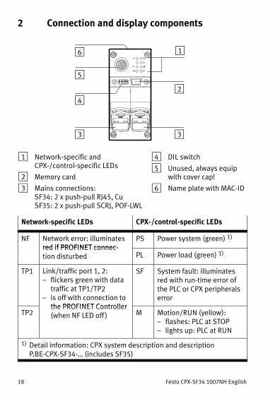
2 Connection and display components
1
24
3
5
3
6
1 Network−specific and CPX−/control−specific LEDs
2 Memory card
3 Mains connections:SF34: 2 x push−pull RJ45, CuSF35: 2 x push−pull SCRJ, POF−LWL
4 DIL switch
5 Unused, always equipwith cover cap!
6 Name plate with MAC−ID
Network−specific LEDs CPX−/control−specific LEDs
NF Network error: illuminatesred if PROFINET connec�
PS Power system (green) 1)
red if PROFINET connec�tion disturbed PL Power load (green) 1)
TP1 Link/traffic port 1, 2:� flickers green with data
traffic at TP1/TP2� is off with connection to
the PROFINET Controller
SF System fault: illuminatesred with run−time error ofthe PLC or CPX peripheralserror
TP2the PROFINET Controller(when NF LED off ) M Motion/RUN (yellow):
� flashes: PLC at STOP� lights up: PLC at RUN
1) Detail information: CPX system description and description P.BE−CPX−SF34−� (includes SF35)

Festo CPX−SF34 1007NH English 19
3 Installation instructions
3.1 Mounting
The control block is mounted in an interlinking block of theCPX terminal.
NoteThe CPX−SF34/35 control block may only be used withCPX−metal interlinking blocks and must be the firstmodule in the CPX terminal (counted from left).
WarningSwitch off the power supply before dismantling ormounting the control block (danger of operativemalfunctions or damage).
1 Screws, tightening torque 0.9 ... 1.1 Nm
2 CPX control block
3 CPX−metal interlinking block,here: CPX−M−GE−EV−S−PP−5POL
3
1
2
1

Festo CPX−SF34 1007NH English20
Dismantling:
· Remove the screws and carefully lift up the controlblock.
Mounting:
1. Check the seal and sealing surfaces and refit theconnection block.
2. Tighten the screws by hand in diagonally oppositesequence. Tightening torque 0.9 ... 1.1 Nm
3.2 Setting the DIL switches
1 DIL switch 1: Boot settings of the PLC
2 DIL switch 2:Reserved
3 Memory card (see section 3.3)
1 2
3

Festo CPX−SF34 1007NH English 21
Boot settings of the PLC with DIL switch 1
DIL switch Setting Function 1)
All DIL switches:OFF (factory setting)
Operating status of the PLC:�PC WORX":The start of the user program is controlled viaPC WORX.
DIL 1.1: ONDIL 1.2: OFFDIL 2.1: OFFDIL 2.2: OFF
Operating status of the PLC:�AUTORUN":The boot program starts as soon as the CPX−SF34/35 is suppliedwith voltage.1)
DIL 1.1: AnyDIL 1.2: ONDIL 2.1: OFFDIL 2.2: OFF
Formatting the memory card:1. Set DIL 2.1 to ON2. Execute POWER OFF/ON
The memory card is nowformatted.
3. Set DIL 2.1 back to OFF
1) No automatic starting with voltage recovery after undervoltage UEL/SEN < 17.5�V
NoteA requirement for automatic starting of the Bootprogram with AUTORUN is that there are no deviationsbetween the actual and nominal configuration.
Festo CPX−SF34 1007NH English22
3.3 Use of the memory card
The memory card serves as carrier of the boot program forsystem start as well as carrier of the user programs andconfiguration data. The PROFINET−IO device name is notstored on the memory card of the CPX−SF34/35. Detailedinformation on use: see description P.BE−CPX−SF34−�(includes SF35).
NoteRisk of malfunctions or damage
Inserting or removing the memory card while the powersupply is switched on can result in malfunctions of ordamage to the memory card.· Disconnect the power supply before you insert orremove the memory card.
The memory card must always be plugged in when theCPX−SF34/35 is started!
Festo CPX−SF34 1007NH English 23
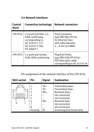
3.4 Network interfaces
Controlblock
Connection technology Network connectors
CPX−SF34 2 x push−pull RJ45, Cu,AIDA conforming,corresponding toIEC�61076−3−117,IEC�61076−3−106,IEC�60603−7
Festo connector, type FBS−RJ45−PP−GS for Ethernet lines with cable diameter 5���8�mm (22 AWG)
CPX−SF35 2 x push−pull socket, SCRJ, AIDA conforming,
Plug from Festo, type FBS−SCRJ−PP−GS for POF fibre−optic cable corresponding to IEC�61754−24
Pin assignment of the network interface of the CPX−SF34:
RJ45 socket Pin Signal Explanation
12345678
8 1
12345678Housing
TD+TD�RD+��RD���FE
Transmitted data+Transmitted data�Received data+not connectednot connectedReceived data�not connectednot connectedScreening/functional earth

Festo CPX−SF34 1007NH English24
Controlblock
Cable specificationNetwork connectors
CPX−SF34 � Cable type:Screened industrial Ethernet line (at least category Cat 5)
� Cable length:max. 100�m between network participants (corresponding to specifications for Ethernet networks, ISO/IEC 11801 and ANSI/TIA/EIA−568−B,PROFINET Installation Guide)
� Wire cross section for max. line length: 22 AWG (for 100�m link length, based on ISO/IEC�11801)
CPX−SF35 � Cable type:POF fibre optic cable
� Cable length:max.�segment length 50�m �between networkparticipants (corresponding to specifications forEthernet networks, ISO/IEC 11801, PROFINETInstallation Guide)
To ensure protection class IP65/IP67, the unused networkconnections must be closed with cover caps. These mustbe ordered separately (type CPX−M−AK−C, part no. 548753)
Festo CPX−SF34 1007NH English 25
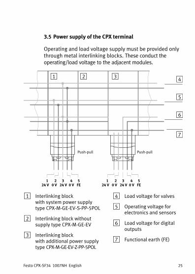
3.5 Power supply of the CPX terminal
Operating and load voltage supply must be provided onlythrough metal interlinking blocks. These conduct theoperating/load voltage to the adjacent modules.
1 2 3 4
5
6
7
Push−pull
1 2 3 4 524�V 0�V 24�V 0�V FE
1 2 3 4 524�V 0�V 24�V 0�V FE
Push−pull
1 Interlinking block with system power supply type CPX−M−GE−EV−S−PP−5POL
2 Interlinking block without supply type CPX−M−GE−EV
3 Interlinking block with additional power supply type CPX−M−GE−EV−Z−PP−5POL
4 Load voltage for valves
5 Operating voltage forelectronics and sensors
6 Load voltage for digitaloutputs
7 Functional earth (FE)
Festo CPX−SF34 1007NH English26
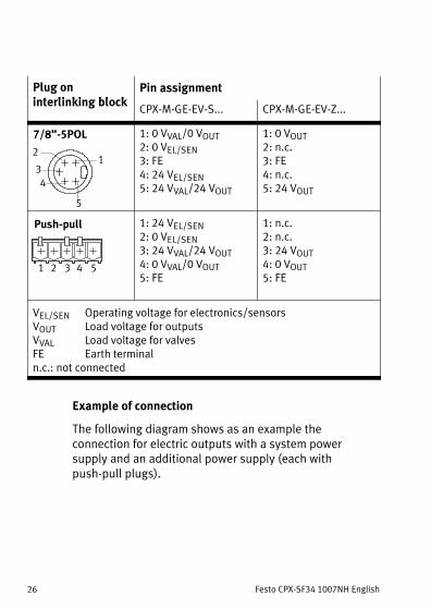
Plug on interlinking block
Pin assignmentinterlinking block
CPX−M−GE−EV−S... CPX−M−GE−EV−Z...
7/8"−5POL
12
34
5
1: 0 VVAL/0 VOUT2: 0 VEL/SEN3: FE4: 24 VEL/SEN5: 24 VVAL/24 VOUT
1: 0 VOUT2: n.c.3: FE4: n.c.5: 24 VOUT
Push−pull
2 3 4 51
1: 24 VEL/SEN2: 0 VEL/SEN3: 24 VVAL/24 VOUT4: 0 VVAL/0 VOUT5: FE
1: n.c.2: n.c.3: 24 VOUT4: 0 VOUT5: FE
VEL/SEN Operating voltage for electronics/sensorsVOUT Load voltage for outputsVVAL Load voltage for valvesFE Earth terminaln.c.: not connected
Example of connection
The following diagram shows as an example theconnection for electric outputs with a system powersupply�and an additional power supply (each withpush−pull plugs).

Festo CPX−SF34 1007NH English 27
1 2
3
4
5
6Push−pullPush−pull
1 Interlinking block with system power supply CPX−M−GE−EV−S−PP−5POL
2 Interlinking block with additional power supply CPX−M−GE−EV−Z−PP−5POL
3 Pin 5: Earth terminal at the push−pull plug designed for 16 A
4 The load voltage for thevalves/outputs can beswitched off separately
5 External fuses
6 Potential equalisation

Festo CPX−SF34 1007NH English28
4 Technical data
General characteristics of CPX−SF34/35
General technical data see CPX system manual P.BE−CPX−SYS−...
Protection class according to EN 60529
IP65/IP67(completely mounted, see specifications in section 3.4)
Protection against electric shockProtection against direct and indirect contact as per IEC/DIN EN 60204−1
by means of PELV circuit(Protected Extra Low Voltage)
Operating voltage/load voltage only through CPX metal interlinking blocks, see section 3.5
Module code (CPX−specific)� CPX−SF34� CPX−SF35
218219
Power supply CPX−SF34 CPX−SF35
Intrinsic current consumption at 24 Vfrom operating voltage supplyfor electronics/sensors (UEL/SEN)
120 mA(internal electronics)
150 mA(internal electronics)
Galvanic isolationPROFINET interfaces for UEL/SEN
galvanically isolated (trans�former, 1500�V)
by means offibre−optic cable
Mains buffering time 10 ms 10 ms

Festo CPX−SF34 1007NH English 29
Network/controller−specific characteristics of CPX−SF34/35
PROFINET� Protocol� Specification
� Transmission technology
PROFINET IO RT (PNIO RT)Industrial Ethernet based on IEEE 802.3Switched Fast Ethernet, 100 Mbit/s
PLC� Programming languages in
accordance with IEC�61131−3� Program memory
� Remanent data memory� Processing speed� Programming interface
AWL/IL, FB, KOP, SFC, ST
2 MB, of which 512�kB for Boot project4 kB1.5 ms per 1000 instructionsfrom AUTOMATIONWORX Software Suite 1.50 SP1

Festo CPX−SF34 1007NH English30
In case of technical problems, please contact technical support of PHOENIX CONTACT GmbH & Co. KG, D−32823 Blomberg, Germany.E−mail: [email protected]
![Terminal CPX Busknoten CPX-(M)-FB33/34/35/41 - festo.com · Beschreibung Netzwerk-Protokoll PROFINET IO 548759 de 1410d [8041493] Terminal CPX Busknoten CPX-(M)-FB33/34/35/41](https://img.pdfslide.org/doc/110x75/5d50ae5b88c993e4488b7e26/terminal-cpx-busknoten-cpx-m-fb33343541-festocom-beschreibung-netzwerk-protokoll.jpg)


![Steuerblock Control block VOFA-L26-T32C-M-G14-1C1- · de Bedienungs anleitung en Operating instructions 8041188 1505a [8041189] Steuerblock Control block VOFA-L26-T32C-M-G14-1C1-](https://img.pdfslide.org/doc/110x75/5bf66c5009d3f20a768c366a/steuerblock-control-block-vofa-l26-t32c-m-g14-1c1-de-bedienungs-anleitung.jpg)
![CPX−Terminal - festo.com · Beschreibung Elektronik System− Beschreibung Installation und Inbetriebnahme von CPX−Terminals CPX−Terminal Beschreibung 526 445 de 0902e [742938]](https://img.pdfslide.org/doc/110x75/5e06219ad034661701220bdd/cpxaterminal-festocom-beschreibung-elektronik-systema-beschreibung-installation.jpg)