Embed Size (px)
Citation preview
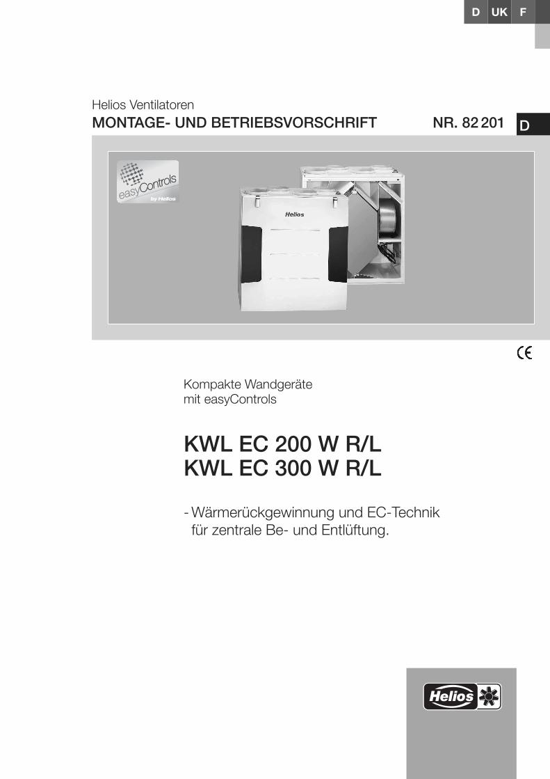
Helios VentilatorenMONTAGE- UND BETRIEBSVORSCHRIFT NR. 82201
Kompakte Wandgerätemit easyControls
KWL EC 200 W R/LKWL EC 300 W R/L
- Wärmerückgewinnung und EC-Technik für zentrale Be- und Entlüftung.
D
UKD F
MONTAGE- UND BETRIEBSVORSCHRIFT
InhaltsverzeichnisKAPITEL 1. ALLGEMEINE MONTAGE- UND BETRIEBSHINWEISE . . . . . . . . . . . . . . . . . . . . . . . . . . . . . . . . . . .Seite 1
1.0 Allgemeine Informationen . . . . . . . . . . . . . . . . . . . . . . . . . . . . . . . . . . . . . . . . . . . . . . . . . . . . . . . . . . . . . . . .Seite 11.1 Warn- und Sicherheitshinweise . . . . . . . . . . . . . . . . . . . . . . . . . . . . . . . . . . . . . . . . . . . . . . . . . . . . . . . . . . .Seite 11.2 Wichtige technische Information . . . . . . . . . . . . . . . . . . . . . . . . . . . . . . . . . . . . . . . . . . . . . . . . . . . . . . . . . .Seite 11.3 Gewährleistung- und Haftungsansprüche . . . . . . . . . . . . . . . . . . . . . . . . . . . . . . . . . . . . . . . . . . . . . . . . . . .Seite 11.4 Vorschriften – Richtlinien . . . . . . . . . . . . . . . . . . . . . . . . . . . . . . . . . . . . . . . . . . . . . . . . . . . . . . . . . . . . . . . .Seite 11.5 Sendungsannahme . . . . . . . . . . . . . . . . . . . . . . . . . . . . . . . . . . . . . . . . . . . . . . . . . . . . . . . . . . . . . . . . . . . .Seite 11.6 Einlagerung . . . . . . . . . . . . . . . . . . . . . . . . . . . . . . . . . . . . . . . . . . . . . . . . . . . . . . . . . . . . . . . . . . . . . . . . . .Seite 11.7 Transport . . . . . . . . . . . . . . . . . . . . . . . . . . . . . . . . . . . . . . . . . . . . . . . . . . . . . . . . . . . . . . . . . . . . . . . . . . . .Seite 11.8 Einsatzbereich – Anwendung . . . . . . . . . . . . . . . . . . . . . . . . . . . . . . . . . . . . . . . . . . . . . . . . . . . . . . . . . . . . .Seite 21.9 Funktion und Wirkungsweise . . . . . . . . . . . . . . . . . . . . . . . . . . . . . . . . . . . . . . . . . . . . . . . . . . . . . . . . . . . . .Seite 21.10 Leistungsdaten . . . . . . . . . . . . . . . . . . . . . . . . . . . . . . . . . . . . . . . . . . . . . . . . . . . . . . . . . . . . . . . . . . . . . . .Seite 21.11 Feuerstätten . . . . . . . . . . . . . . . . . . . . . . . . . . . . . . . . . . . . . . . . . . . . . . . . . . . . . . . . . . . . . . . . . . . . . . . . .Seite 21.12 Technische Daten . . . . . . . . . . . . . . . . . . . . . . . . . . . . . . . . . . . . . . . . . . . . . . . . . . . . . . . . . . . . . . . . . . . . .Seite 31.13 RJ-Anschlüsse KWL-Steuerungskonzept . . . . . . . . . . . . . . . . . . . . . . . . . . . . . . . . . . . . . . . . . . . . . . . . . . .Seite 3
KAPITEL 2. MONTAGE . . . . . . . . . . . . . . . . . . . . . . . . . . . . . . . . . . . . . . . . . . . . . . . . . . . . . . . . . . . . . . . . . . . . . .Seite 42.0 Aufstellung . . . . . . . . . . . . . . . . . . . . . . . . . . . . . . . . . . . . . . . . . . . . . . . . . . . . . . . . . . . . . . . . . . . . . . . . . . .Seite 42.1 Wandmontage . . . . . . . . . . . . . . . . . . . . . . . . . . . . . . . . . . . . . . . . . . . . . . . . . . . . . . . . . . . . . . . . . . . . . . . .Seite 42.2 Kondensatablauf . . . . . . . . . . . . . . . . . . . . . . . . . . . . . . . . . . . . . . . . . . . . . . . . . . . . . . . . . . . . . . . . . . . . . .Seite 52.3 Montage Elektro-Vorheizung KWL-EVH ... W (Zubehör) . . . . . . . . . . . . . . . . . . . . . . . . . . . . . . . . . . . . . . . . .Seite 72.4 Anschlussmuffen . . . . . . . . . . . . . . . . . . . . . . . . . . . . . . . . . . . . . . . . . . . . . . . . . . . . . . . . . . . . . . . . . . . . . .Seite 82.5 Luftführung, Lüftungsleitung . . . . . . . . . . . . . . . . . . . . . . . . . . . . . . . . . . . . . . . . . . . . . . . . . . . . . . . . . . . . .Seite 82.6 Gerätedämmung . . . . . . . . . . . . . . . . . . . . . . . . . . . . . . . . . . . . . . . . . . . . . . . . . . . . . . . . . . . . . . . . . . . . . .Seite 82.7 Elektrischer Anschluss . . . . . . . . . . . . . . . . . . . . . . . . . . . . . . . . . . . . . . . . . . . . . . . . . . . . . . . . . . . . . . . . . .Seite 82.8 Funktionsschema . . . . . . . . . . . . . . . . . . . . . . . . . . . . . . . . . . . . . . . . . . . . . . . . . . . . . . . . . . . . . . . . . . . . .Seite 92.9 Erstinbetriebnahme und Einregulierung . . . . . . . . . . . . . . . . . . . . . . . . . . . . . . . . . . . . . . . . . . . . . . . . . . . . .Seite 9
KAPITEL 3. SERVICE UND WARTUNG . . . . . . . . . . . . . . . . . . . . . . . . . . . . . . . . . . . . . . . . . . . . . . . . . . . . . . . .Seite 103.0 Service und Wartung . . . . . . . . . . . . . . . . . . . . . . . . . . . . . . . . . . . . . . . . . . . . . . . . . . . . . . . . . . . . . . . . . .Seite 103.1 Kreuzgegenstrom-Wärmetauscher . . . . . . . . . . . . . . . . . . . . . . . . . . . . . . . . . . . . . . . . . . . . . . . . . . . . . . .Seite 103.2 Filterwechsel . . . . . . . . . . . . . . . . . . . . . . . . . . . . . . . . . . . . . . . . . . . . . . . . . . . . . . . . . . . . . . . . . . . . . . . .Seite 103.3 Kondensatablauf im Gerät . . . . . . . . . . . . . . . . . . . . . . . . . . . . . . . . . . . . . . . . . . . . . . . . . . . . . . . . . . . . . .Seite 113.4 Zugang zum internen Klemmenkasten . . . . . . . . . . . . . . . . . . . . . . . . . . . . . . . . . . . . . . . . . . . . . . . . . . . . .Seite 113.5 Demontage Außenluftgebläse . . . . . . . . . . . . . . . . . . . . . . . . . . . . . . . . . . . . . . . . . . . . . . . . . . . . . . . . . . .Seite 113.6 Demontage Elektro-Vorheizung KWL-EVH ... W . . . . . . . . . . . . . . . . . . . . . . . . . . . . . . . . . . . . . . . . . . . . . .Seite 123.7 Montage der Kabelverschraubung zur Zugentlastung . . . . . . . . . . . . . . . . . . . . . . . . . . . . . . . . . . . . . . . . .Seite 123.8 Sonstiges Zubehör . . . . . . . . . . . . . . . . . . . . . . . . . . . . . . . . . . . . . . . . . . . . . . . . . . . . . . . . . . . . . . . . . . .Seite 133.9 Anschlussbaugruppen mit Erweiterungsmodul . . . . . . . . . . . . . . . . . . . . . . . . . . . . . . . . . . . . . . . . . . . . . .Seite 13
KAPITEL 4. ABMESSUNGEN . . . . . . . . . . . . . . . . . . . . . . . . . . . . . . . . . . . . . . . . . . . . . . . . . . . . . . . . . . . . . . . .Seite 144.0 Abmessungen . . . . . . . . . . . . . . . . . . . . . . . . . . . . . . . . . . . . . . . . . . . . . . . . . . . . . . . . . . . . . . . . . . . . . . .Seite 14
KAPITEL 5. SCHALTPLAN/VERDRAHTUNGSPLAN . . . . . . . . . . . . . . . . . . . . . . . . . . . . . . . . . . . . . . . . . . . . . .Seite 155.0 Standard Anschlussplan SS-1042 . . . . . . . . . . . . . . . . . . . . . . . . . . . . . . . . . . . . . . . . . . . . . . . . . . . . . . . .Seite 155.1 Verdrahtungsplan KWL EC 200/300 W R/L . . . . . . . . . . . . . . . . . . . . . . . . . . . . . . . . . . . . . . . . . . . . . . . . .Seite 165.2 Gerätetypenschild . . . . . . . . . . . . . . . . . . . . . . . . . . . . . . . . . . . . . . . . . . . . . . . . . . . . . . . . . . . . . . . . . . . .Seite 17
KAPITEL 6. HÄUFIGE FRAGEN6.0 Häufige Fragen . . . . . . . . . . . . . . . . . . . . . . . . . . . . . . . . . . . . . . . . . . . . . . . . . . . . . . . . . . . . . . . . . . . . . .Seite 17
DEUTSCH
Dieses Produkt enthält Batterien bzw. Akkus. Nach dem Batteriegesetz (BattG) sind wir verpflichtet, auf Folgendes hinzuweisen:Batterien und Akkus dürfen nicht im Hausmüll entsorgt werden. Sie sind zur Rückgabe gebrauchter Batterien und Akkus gesetzlich verpflichtet. Sie können Batterienund Akkus im Handel oder in kommunalen Sammelstellen unentgeltlich zurückgeben.Batterien oder Akkus, die Schadstoffe enthalten, sind mit einem Symbol einer durchgekreuzten Mülltonne gekennzeichnet. Unter dem Mülltonnen-Symbol befindetsich die chemische Bezeichnung des Schadstoffes.
Cd für Cadmium, Pb für Blei und Hg für Quecksilber
Denken Sie an unsere Umwelt, mit der Rückgabe leisten Sie einen wesentlichen Beitrag zum Umweltschutz!
1.0 Allgemeine InformationenZur Sicherstellung einer einwandfreien Funktion und zur eigenen Sicherheit sind alle nachstehenden Vorschriften genaudurchzulesen und zu beachten. National einschlägigen Normen, Sicherheitsbestimmungen und Vorschriften (z.B. DINEN VDE 0100) sowie die TAB des EVUs sind unbedingt zu beachten und anzuwenden.Das Planungsbüro erstellt die für die Systemberechnung erforderlichen Planungsunterlagen. Zusätzliche Informationenoder eine detaillierte Planung (kostenpflichtige Leistung) kann bei Helios angefragt werden. Die Montage- und Betriebs-vorschrift als Referenz am Gerät aufbewahren. Nach der Endmontage muss dem Betreiber (Mieter/Eigentümer) dasDokument ausgehändigt werden.
Gliederung der Montage- und Betriebsvorschrift: Kapitel 1 – 3 Allgemeine Montage, Betriebshinweise, Gerätemontage und Erstinbetriebnahme bzw. Einregulierung
– ist für den Fachinstallateur bestimmt Kapitel 4 – 5 Zubehör + Service und Wartung
– ist für den Fachinstallateur und Endkunden bestimmtIn der im Lieferumfang enthalten Betriebsanleitung „ easyControls“ (Nr. 82 200) sind alle Informationen zur Bedienungund Steuerung der Kompaktgeräte zu finden. Diese Betriebsanleitung ist für den Fachinstallateur und den Endkundenbestimmt.
1.1 Warn- und Sicherheitshinweise Nebenstehendes Symbol ist ein sicherheitstechnischer Warnhinweis. Alle Sicherheitsvorschriften bzw. Symbolemüssen unbedingt beachtet werden, damit jegliche Gefahrensituation vermieden wird.
1.2 Wichtige technische Information Die KWL EC 200/300 W R/L besitzen einen Türkontaktschalter. Wird die frontseitige Tür entfernt, erfolgt eine allpolige Trennung der Versorgungsspannung im geräteinternen Klemmenkasten. Somit sind normale Wartungsarbeiten z.B.:
Überprüfung Kondensatablauf, Filterwechsel, Reinigung Wärmetauscher, Montage der Vorheizung (Zubehör) möglich.Das Öffnen des geräteinternen Klemmenkastens, darf nur von einer autorisierten Elektrofachkraft durchgeführtwerden! Die geeigneten Maßnahmen sind in Kapitel 2 zu finden.
1.3 Gewährleistungs- und Haftungsansprüche Zur Wahrung der Gewährleistungs- und Haftungsansprüche des Kunden sind zwingend nachfolgende Ausführungenzu beachten: – Umsetzung nach Montage und Betriebsvorschrift „ Gerät“ – Umsetzung nach Bedienungsanleitung „ easyControls” – Die Verwendung von Zubehörteilen, die nicht von Helios freigegeben, empfohlen oder angeboten werden, ist nicht
zulässig. Even tuell auftretende Schäden unterliegen nicht der Gewährleistung.Wenn diese Ausführungen nicht beachtet werden, entfällt unsere Gewährleistung. Gleiches gilt für Haftungsansprüchean den Hersteller.
1.4 Vorschriften – RichtlinienBei ordnungsgemäßer Installation und bestimmungsgemäßem Betrieb entspricht das kompakte KWL-Wandgerät denzum Zeit punkt seiner Herstellung gültigen Vorschriften und CE-Richtlinien.
1.5 SendungsannahmeDie Lieferung enthält den Gerätetyp: KWL EC 200 W R/L
oder den Gerätetyp: KWL EC 300 W R/L Die Sendung ist sofort bei Anlieferung auf Beschädigungen und Typenrichtigkeit zu prüfen. Falls Schäden vorliegen,unverzüglich Schadensmeldung unter Hinzuziehung des Transportunternehmens veranlassen. Bei nicht fristgerechterReklamation gehen evtl. Ansprüche verloren.
1.6 EinlagerungBei Einlagerung über einen längeren Zeitraum sind zur Verhinderung schädlicher Einwirkungen folgende Maßnahmen zutreffen: Schutz durch trockene, luft- und staubdichte Verpackung (Kunststoffbeutel mit Trockenmittel und Feuchtigkeit-sindikatoren). Der Lagerort muss erschütterungsfrei, wassergeschützt und frei von übermäßigen Temperaturschwan-kungen sein. Schäden, deren Ursprung in unsachgemäßem Transport, unsachgemäßer Einlagerung oder Inbetriebnah-me liegen, sind nachweisbar und unterliegen nicht der Gewährleistung.
1.7 Transport Das Gerät ist werkseitig so verpackt, dass es gegen normale Transportbelastungen geschützt ist. Führen Sie den Transport sorgfältig durch. Es wird empfohlen, das Gerät bis zur Aufstellung in der Originalverpackung zu belassen, um mögliche Beschädigungen und Verschmutzungen zu vermeiden.
1
Kompakte Wandgeräte KWL EC 200/300 W R/LMontage- und Betriebsvorschrift
KAPITEL 1
ALLGEMEINE MONTAGE-UND BETRIEBSHINWEISE
DHerzlichen Glückwunsch zum Erwerb eines Premiumproduktes von Helios Ventilatoren. Als Helios Kunde profitieren Sie von der langjährigen Erfahrung des Unternehmens in der Bran-che und erhalten einen Artikel in Premiumqualität. Alle KWL EC 200/300 W R/L Geräte werden bereits bei der Produktion auf ihre Funktionsfähigkeit geprüft.Dabei werden nicht nur die offensichtlichen Funktionen (z.B. Betrieb der Ventilatoren) getestet, sondern auch diese, bei welchen Sie als Kunde selbst keineTests durchführen können. Dazu zählen beispielsweise die interne und externe Leckage und die elektrische Sicherheit. Außerdem wird Ihnen durch innovativeIdeen im Bereich der Steuerungs- und Regelungstechnik eine Reduktion der Betriebskosten ermöglicht.
Sollten Sie unerwartet dennoch ein Problem mit unserm Gerät haben, können Sie sich an den Fachinstallateur oder unseren Helios Kundendienst wenden.
�
WARNUNG �
WICHTIG �
TIPP!TIPP!
TIPP!TIPP!
1.8 Einsatzbereich – AnwendungKompaktgeräte KWL EC 200/300 W .. R/L mit Wärmerückgewinnung, für die zentrale Be- und Entlüftung von Wohn-häusern und Etagenwohnungen. Ausgestattet mit easyControls, dem innovativen Steuerungskonzept für einfachsteNetzwerkanbindung und Webbrowser-Bedienung. Mit hoch effizientem Kreuzgegenstrom-Wärmetauscher aus Kunst-stoff, mit einem Wärmebereitstellungsgrad von, siehe Tabelle:
Die serienmäßige Ausstattung erlaubt die Aufstellung und den Einsatz in frostfreien Räumen über +5 °C. Bei Betriebunter erschwerten Bedingungen, wie z.B. hohe Feuchtigkeit, längere Stillstandzeiten, starke Verschmutzung, übermä-ßige Beanspruchung durch klimatische sowie technische, elektronische Einflüsse, ist eine Rückfrage und Einsatzfreiga-be erforderlich, da die Serienausführung hierfür u. U. nicht geeignet ist. Ein bestimmungsfremder Einsatz ist nicht zulässig!
1.9 Funktion und WirkungsweiseDas KWL-Kompaktgerät besitzt einen Kreuz-Gegenstromwärmetauscher aus Kunststoff, in welchem sich die Außenluft(Frischluft) und die Gebäudeabluft kreuzen, ohne direkt miteinander in Verbindung zu kommen. Hierbei gibt die Abluftden größten Teil der Wärme an die Außenluft ab. Die Zuluft wird durch das Rohrsystem zu den Zuluft benötigendenRäumen (Wohn- und Schlafräume) geleitet. Die Abluft wird aus den untergeordneten Räumen (wie z.B. Küche, Toilet-ten, Duschen u.v.m.) abgesaugt. Sie strömt durch das Rohrsystem zum Lüftungsgerät zurück, gibt Wärme ab und wirddurch die Fortluftleitung ins Freie geführt.Der Wärmebereitstellungsgrad hängt von den Faktoren Feuchte der Luft und Temperaturunterschied der Außenluft undAbluft ab. Der Volumenstrom kann über den im Lieferumfang enthaltenen lokalen WEB-Server (LAN-Anschluss) alsauch über die (optional erhältlichen) Bedienelemente KWL-BE oder KWL-BEC geregelt werden.Eine bedarfsgerechte Regelung kann durch die optionalen Fühler KWL-VOC = Luftqualitätsfühler, KWL-CO2 = Kohlen-dioxid-Fühler oder KWL-FTF = Feuchte-Temperatur-Fühler oder durch die integrierte Wochenzeitschaltuhr erfolgen.
Die elektrische Vorheizung KWL-EVH ... W (Zubehör, Best-Nr. 4224) erwärmt die Außenluft und verhindert bei sehrniedrigen Außentemperaturen eine Vereisung des Wärmetauschers und garantiert dessen sichere Funktion für eineoptimale Wärmerückgewinnung im Winter. Fortlufttemperatur einstellbar von 0 °C bis +10 °C. Durch Ansteuerung einerleistungsgeregelten, externen Elektro- oder Warmwasser-Nachheizung (Zubehör EHR-R...oder WHR...) kann auch dieZulufttemperatur zusätzlich erwärmt werden.
Für warme Jahreszeiten ist der Sommer-Bypass die optimale Lösung, um kühlere Außenluft in das Gebäude zu leiten.Durch die integrierten Filter wird die Luft optimal gereinigt. Dies sorgt für ein hygienisches Gerät. Serienmäßig ist in derAußenluft ein G4-Filter und in der Abluft ein G4-Filter eingebaut. Optional kann zusätzlich ein F7-Filter in den Zuluftbe-reich nach dem Wärmetauscher eingesetzt werden. Voraussetzung für eine dauerhafte einwandfreie Funktion des Lüf-tungsgerätes ist jedoch der regelmäßige Filtertausch und Wartung des KWL-Gerätes.
Ersatzluftfilter können im Internet unter www.ersatzluftfilter.de bestellt werden.
1.10 LeistungsdatenUm die geplanten Leistungsdaten (z.B. optimaler Volumenstrom, geringer Schall und Stromaufnahme) zu erreichen, istauf eine korrekt geplante und ausgeführte Luftverteilung (Außenluft/Zuluft und Abluft/Fortluft) zu achten. Des Weiterenmuss diese entsprechend dimensioniert sein.
Helios bietet regelmäßig Praxisworkshops zu diesem Thema an, in welchen praxisnah zur Planung und Installation allewichtigen Details vermittelt werden. Die Termine sind auf unserer Website www.heliosventilatoren.de unter Schulung.
Abweichende Ausführungen, ungünstige Einbau- und Betriebsbedingungen können zu einer Reduzierung der Förder-leistung oder zu einem erhöhten Schallpegel führen. Die Angaben für das luftseitige Geräusch erfolgen als A-bewerteterSchallleistungspegel LWA (entspricht DIN 45635, T.1). Angaben in A-bewertetem Schalldruck LPA werden von raum-und installationsspezifischen Gegebenheiten beeinflusst. Dementsprechend ergeben sich Abweichungen zu den Anga-ben.
1.11 FeuerstättenDie einschlägig geltenden Vorschriften für den gemeinsamen Betrieb von Feuerstätte, Wohnungslüftung, Dun-stabzugshaube (Info über den Bundesverband des Schornsteinfegerhandwerks-Zentralinnungsverband (ZIV)) sindzu beachten!
– Allgemeine baurechtliche AnforderungenDie KWL-Geräte mit Wärmerückgewinnung dürfen nur dann in Räumen mit anderen raumluftabhängigen Feuerstätteninstalliert und betrieben werden, wenn deren Abgasabführung durch besondere Sicherheitseinrichtungen (bauseits)überwacht wird, die im Auslösefall das KWL-Gerät spannungslos schalten. Das KWL-Gerät wird solange ausgeschaltetbis die Feuerstätte nicht mehr aktiv ist. Dabei muss sichergestellt werden, dass durch den Betrieb der KWL-Geräte keingrößerer Unterdruck als 4 Pa in der Wohneinheit erzeugt wird.Das KWL-Gerät darf nicht gleichzeitig mit Festbrennstoff-Feuerstätten und nicht in Wohneinheiten mit raumluftabhängi-gen Feuerstätten, die an mehrfach belegte Abgasanlagen angeschlossen sind, betrieben werden.
2
Kompakte Wandgeräte KWL EC 200/300 W R/LMontage- und Betriebsvorschrift
D
Gerätetype Soll-Volumenstrom [m³/h] 120 168 251
KWL EC 200 W R/L Wärmebereitstellungsgrad bis zu 90 % 85 % 84 %
KWL EC 300 W R/L Wärmebereitstellungsgrad bis zu 90 % 85 % 84 %
WICHTIG �
WICHTIG �
TIPP!TIPP!
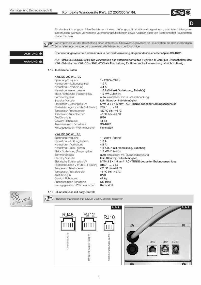
RJ12
Steu
erle
itun
g RJ
10 (
digi
tal
)
RJ45
Steu
erle
itun
g RJ
12 (
Anal
og )
RJ10
TCP/
IP V
erbi
ndun
g
Abb.1 Abb.2
RJ45 RJ12 RJ10
TIPP!TIPP!
Für den bestimmungsgemäßen Betrieb der mit einem Lüftungsgerät mit Wärmerückgewinnung errichteten Lüftungsan-lage müssen eventuell vorhandene Verbrennungsluftleitungen sowie Abgasanlagen von Festbrennstoff-Feuerstättenabsperrbar sein.
Wir empfehlen vor der Beschaffung eines Unterdruck-Überwachungssystem für Feuerstätten mit dem zuständigenSchornsteinfeger zu sprechen, um eventuelle Wünsche zu berücksichtigen.
Überwachungssysteme werden immer in der Gerätezuleitung eingebunden! (siehe Schaltplan SS-1042)
ACHTUNG LEBENSGEFAHR! Die Verwendung des externen Kontaktes (Funktion 1; Gerät Ein- /Ausschalten) desKWL-EM oder der KWL-CO2 / KWL-VOC als Abschaltung für Unterdruck-Überwachung ist nicht zulässig.
1.12 Technische Daten
KWL EC 200 W .. R/L Spannung/Frequenz 1~ 230 V~/50 Hz Nennstrom – Lüftungsbetrieb 1,0 A Nennstrom – Vorheizung 4,4 A Nennstrom – max. gesamt 1,0 A (5,4 inkl. Vorheizung, Zubehör)
Elektr. Vorheizung (Ausgang) kW 1,0 kW (Zubehör) Sommer Bypass auto (einstellbar), mit TauscherabdeckungStandby-Verluste kein Standby-Betrieb möglich Elektrische Zuleitung bis UV NYM-J 3 x 1,5 mm2 ACHTUNG! doppelter ErdungsanschlussFörderleistungen V m3/h (3-4 Stufen) 235 / ... / 18
Temperatur Arbeitsbereich -20 °C bis +40 °CTemperatur Aufstellbereich +5 °C bis +40 °CAusführung in IP20Gewicht Rohbauset 41 kg
Anschluss nach Schaltplan SS-1042 Kreuzgegenstrom-Wärmetauscher Kunststoff KWL EC 300 W .. R/L Spannung/Frequenz 1~ 230 V~/50 Hz Nennstrom – Lüftungsbetrieb 1,3 A Nennstrom – Vorheizung 4,4 A Nennstrom – max. gesamt 1,8 A (5,7 inkl. Vorheizung, Zubehör)
Elektr. Vorheizung (Ausgang) kW 1,0 kW (Zubehör) Sommer Bypass auto (einstellbar), mit TauscherabdeckungStandby-Verluste kein Standby-Betrieb möglich Elektrische Zuleitung bis UV NYM-J 3 x 1,5 mm2 ACHTUNG! doppelter ErdungsanschlussFörderleistungen V m3/h (3-4 Stufen) 315 / ... / 55
Temperatur Arbeitsbereich -20 °C bis +40 °CTemperatur Aufstellbereich +5 °C bis +40 °CAusführung in IP20Gewicht Rohbauset 42 kg
Anschluss nach Schaltplan SS-1042 Kreuzgegenstrom-Wärmetauscher Kunststoff
1.13 RJ-Anschlüsse mit easyControls
Anwender-Handbuch (Nr. 82200) „ easyControls” beachten
ACHTUNG �
WARNUNG �
3
Kompakte Wandgeräte KWL EC 200/300 W R/LMontage- und Betriebsvorschrift
D
2.0 AufstellungDas KWL-Kompaktgerät ist für die „ hängende“ Anordnung zur Installation an der Wand oder zum Einbau in einenSchrank konzipiert und somit für eine Installation innerhalb der Wohnung/Raumeinheit vorgesehen. Aufgrund vonBetriebsgeräuschen, die sich je nach Anlagendruck verändern, wird empfohlen das KWL-Gerät im Waschraum, Flur,Technikräumen, Abstellräume oder in Aufenthaltsräumen aufzustellen. Darauf achten, dass im Installationsbereich einAbwasseranschluss vorhanden ist. Hierzu auch Hinweise unter Punkt 2.2 “Kondensatablauf“ beachten! Die Montage soll so erfolgen, dass möglichst kurze Lüftungsleitungen sowie deren problemloser Anschluss an dasGerät möglich sind. Enge Bögen führen zu erhöhten Druckverlusten und Strömungsgeräuschen. Die Lüftungsleitungendürfen keinesfalls geknickt werden. Auf feste und dichte Befestigung an den Anschlussstutzen ist zu achten. Für War-tungs- und Installationsarbeiten muss das Gerät bzw. Klemmenkasten frei zugänglich sein.
Wichtige Hinweise:1. Zugang zum Klemmenkasten nur durch Ausbau des Wärmetauschers möglich, vorher Frontdeckel öffnen.2. Wird eine externe Vorheizung bzw. Nachheizung verbaut, muss das Rohr mind. 1 m vor und nach dem Heiz- register aus nicht brennbarem Material sein (siehe Funktionsschema Abb.24).3. Die Heizung muss so eingebaut sein, dass der Elektrokasten leicht zugänglich ist. 4. Um Schallübertragungen zu vermeiden, muss je nach Bausubstanz bauseits eine geeignete Schallentkopp- lung vorgesehen werden.5. Bei der Aufstellung des KWL-Kompaktgerätes muss ein ausreichend zugänglicher Revisionsraum vorgese- hen werden (Kurzanleitung Nr. 82041 beachten).6. Die Aufstellung darf nur in frostfreien Räumen erfolgen, da die Gefahr des Einfrierens besteht. Die Raumtem- peratur darf nicht unter +5 °C sinken.
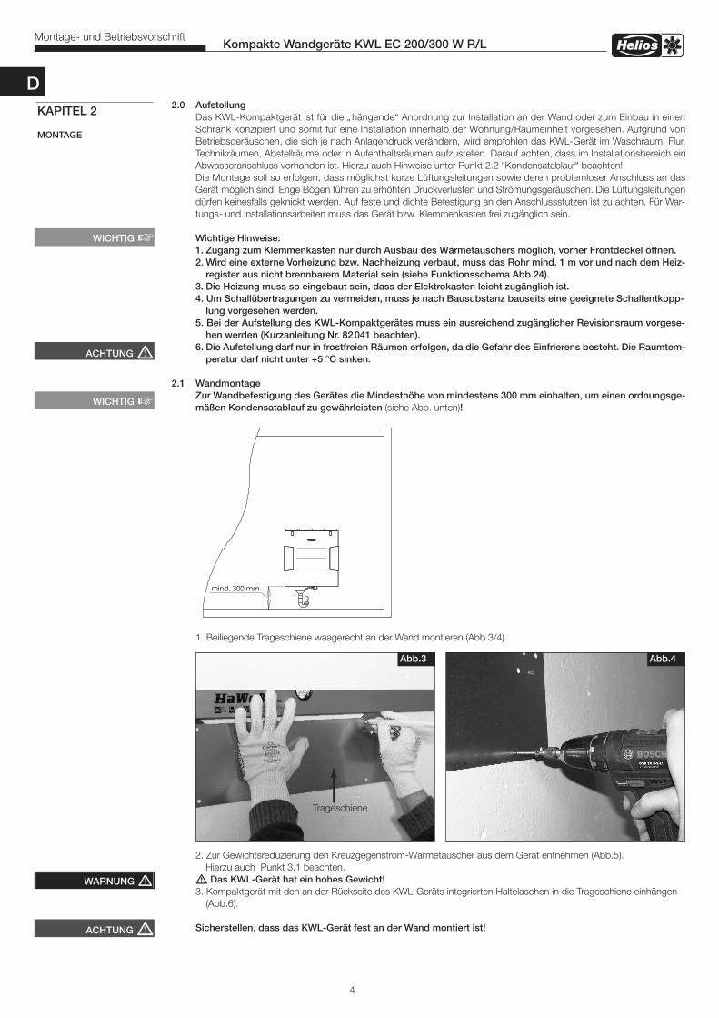
2.1 WandmontageZur Wandbefestigung des Gerätes die Mindesthöhe von mindestens 300 mm einhalten, um einen ordnungsge-mäßen Kondensatablauf zu gewährleisten (siehe Abb. unten)!
1. Beiliegende Trageschiene waagerecht an der Wand montieren (Abb.3/4).
2. Zur Gewichtsreduzierung den Kreuzgegenstrom-Wärmetauscher aus dem Gerät entnehmen (Abb.5). Hierzu auch Punkt 3.1 beachten.� Das KWL-Gerät hat ein hohes Gewicht!3. Kompaktgerät mit den an der Rückseite des KWL-Geräts integrierten Haltelaschen in die Trageschiene einhängen (Abb.6).
Sicherstellen, dass das KWL-Gerät fest an der Wand montiert ist!
4
Kompakte Wandgeräte KWL EC 200/300 W R/LMontage- und Betriebsvorschrift
KAPITEL 2
MONTAGE
ACHTUNG �
WICHTIG �
WICHTIG �
ACHTUNG �
WARNUNG �
mind. 300 mm
Abb.3 Abb.4
Trageschiene
D
5
Kompakte Wandgeräte KWL EC 200/300 W R/LMontage- und Betriebsvorschrift
ACHTUNG �
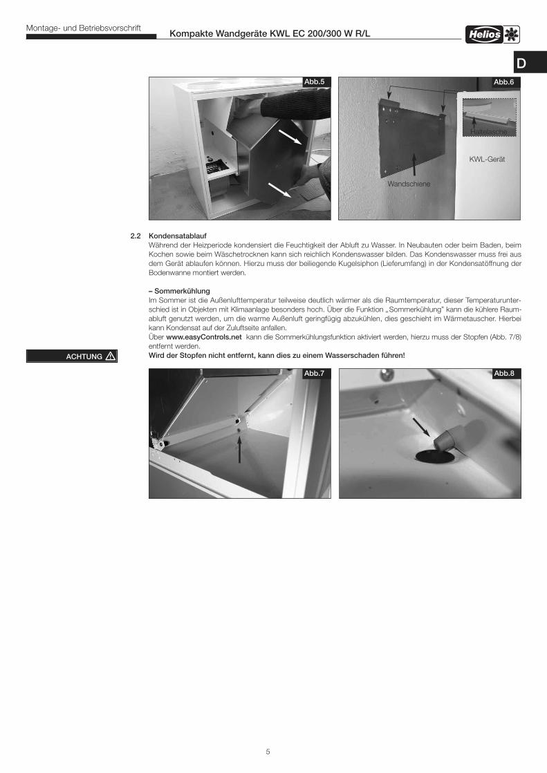
Abb.5 Abb.6
KWL-Gerät
Wandschiene
Abb.7 Abb.8
Haltelasche
2.2 Kondensatablauf Während der Heizperiode kondensiert die Feuchtigkeit der Abluft zu Wasser. In Neubauten oder beim Baden, beim Kochen sowie beim Wäschetrocknen kann sich reichlich Kondenswasser bilden. Das Kondenswasser muss frei aus dem Gerät ablaufen können. Hierzu muss der beiliegende Kugelsiphon (Lieferumfang) in der Kondensatöffnung der
Bodenwanne montiert werden.
– Sommerkühlung Im Sommer ist die Außenlufttemperatur teilweise deutlich wärmer als die Raumtemperatur, dieser Temperaturunter- schied ist in Objekten mit Klimaanlage besonders hoch. Über die Funktion „ Sommerkühlung” kann die kühlere Raum- abluft genutzt werden, um die warme Außenluft geringfügig abzukühlen, dies geschieht im Wärmetauscher. Hierbei kann Kondensat auf der Zuluftseite anfallen. Über www.easyControls.net kann die Sommerkühlungsfunktion aktiviert werden, hierzu muss der Stopfen (Abb. 7/8) entfernt werden. Wird der Stopfen nicht entfernt, kann dies zu einem Wasserschaden führen!
D
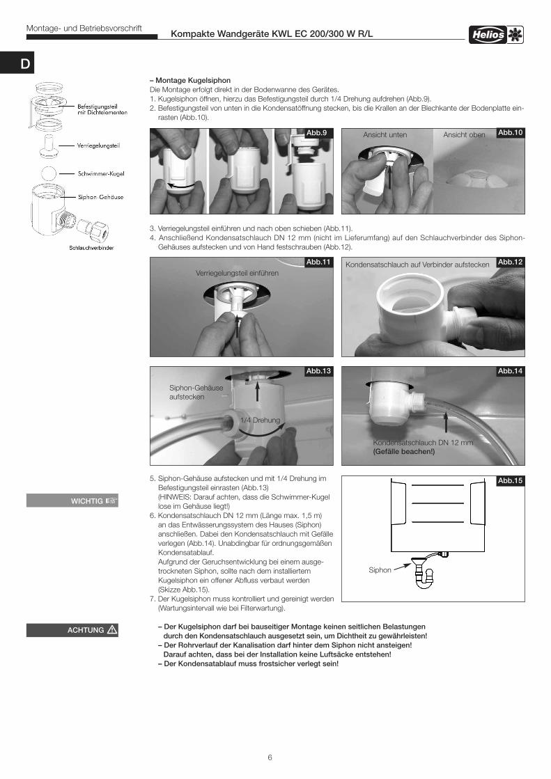
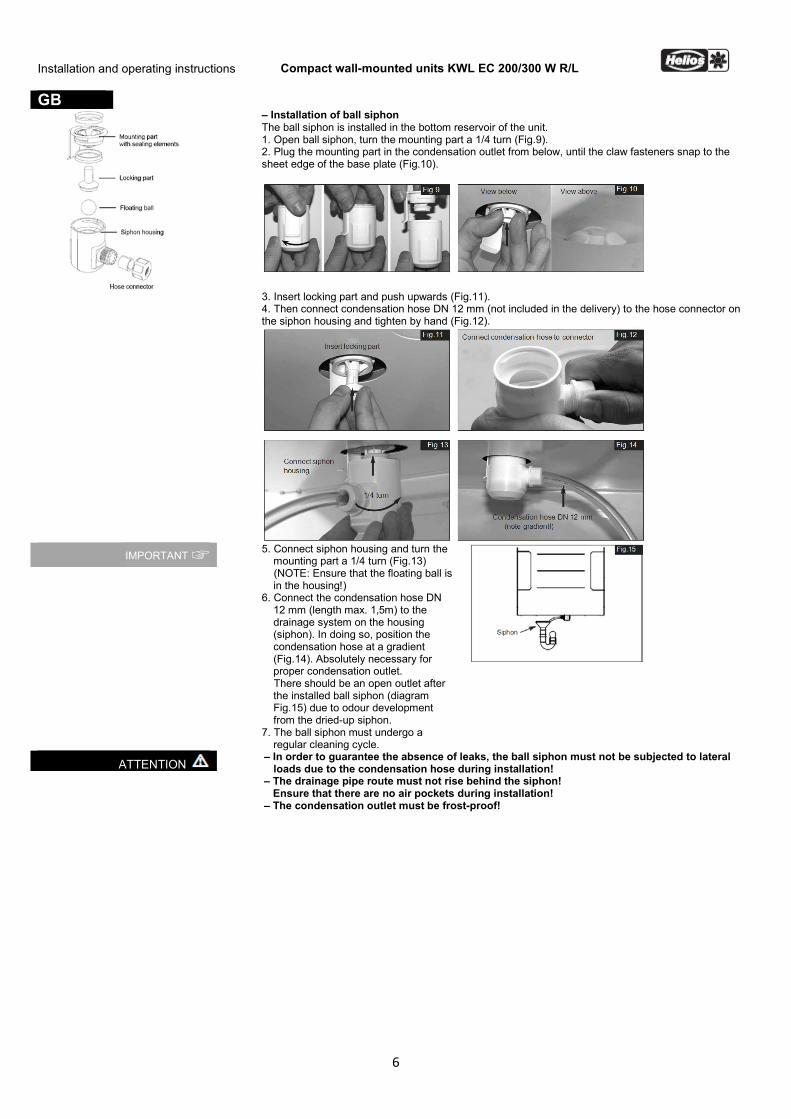
– Montage KugelsiphonDie Montage erfolgt direkt in der Bodenwanne des Gerätes.1. Kugelsiphon öffnen, hierzu das Befestigungsteil durch 1/4 Drehung aufdrehen (Abb.9).2. Befestigungsteil von unten in die Kondensatöffnung stecken, bis die Krallen an der Blechkante der Bodenplatte ein- rasten (Abb.10).
3. Verriegelungsteil einführen und nach oben schieben (Abb.11).4. Anschließend Kondensatschlauch DN 12 mm (nicht im Lieferumfang) auf den Schlauchverbinder des Siphon- Gehäuses aufstecken und von Hand festschrauben (Abb.12).
5. Siphon-Gehäuse aufstecken und mit 1/4 Drehung im Befestigungsteil einrasten (Abb.13) (HINWEIS: Darauf achten, dass die Schwimmer-Kugel lose im Gehäuse liegt!)6. Kondensatschlauch DN 12 mm (Länge max. 1,5 m) an das Entwässerungssystem des Hauses (Siphon) anschließen. Dabei den Kondensatschlauch mit Gefälle verlegen (Abb.14). Unabdingbar für ordnungsgemäßen Kondensatablauf. Aufgrund der Geruchsentwicklung bei einem ausge- trockneten Siphon, sollte nach dem installiertem Kugelsiphon ein offener Abfluss verbaut werden (Skizze Abb.15). 7. Der Kugelsiphon muss kontrolliert und gereinigt werden (Wartungsintervall wie bei Filterwartung).
– Der Kugelsiphon darf bei bauseitiger Montage keinen seitlichen Belastungen durch den Kondensatschlauch ausgesetzt sein, um Dichtheit zu gewährleisten! – Der Rohrverlauf der Kanalisation darf hinter dem Siphon nicht ansteigen! Darauf achten, dass bei der Installation keine Luftsäcke entstehen! – Der Kondensatablauf muss frostsicher verlegt sein!
6
Kompakte Wandgeräte KWL EC 200/300 W R/LMontage- und Betriebsvorschrift
Abb.14Abb.13
Kondensatschlauch DN 12 mm(Gefälle beachen!)
1/4 Drehung
Siphon-Gehäuseaufstecken
Abb.15
Siphon
ACHTUNG �
WICHTIG �
Abb.12Abb.11
Verriegelungsteil einführenKondensatschlauch auf Verbinder aufstecken
Abb.10Abb.9 Ansicht unten Ansicht oben
D
7
Kompakte Wandgeräte KWL EC 200/300 W R/LMontage- und Betriebsvorschrift
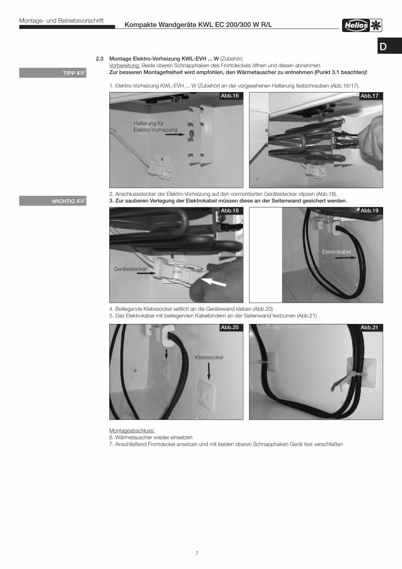
2.3 Montage Elektro-Vorheizung KWL-EVH ... W (Zubehör) Vorbereitung: Beide oberen Schnapphaken des Frontdeckels öffnen und diesen abnehmen. Zur besseren Montagefreiheit wird empfohlen, den Wärmetauscher zu entnehmen (Punkt 3.1 beachten)! 1. Elektro-Vorheizung KWL-EVH ... W (Zubehör) an der vorgesehenen Halterung festschrauben (Abb.16/17).
2. Anschlussstecker der Elektro-Vorheizung auf den vormontierten Gerätestecker clipsen (Abb.18). 3. Zur sauberen Verlegung der Elektrokabel müssen diese an der Seitenwand gesichert werden.
4. Beiliegende Klebesockel seitlich an die Gerätewand kleben (Abb.20) 5. Das Elektrokabel mit beiliegenden Kabelbindern an der Seitenwand festzurren (Abb.21) .
Montageabschluss: 6. Wärmetauscher wieder einsetzen 7. Anschließend Frontdeckel ansetzen und mit beiden oberen Schnapphaken Gerät fest verschließen
Abb.18
Abb.17Abb.16
TIPP �
Halterung für Elektro-Vorheizung
Abb.19
Abb.20 Abb.21
Klebesockel
Gerätestecker
WICHTIG �
D
Elektrokabel
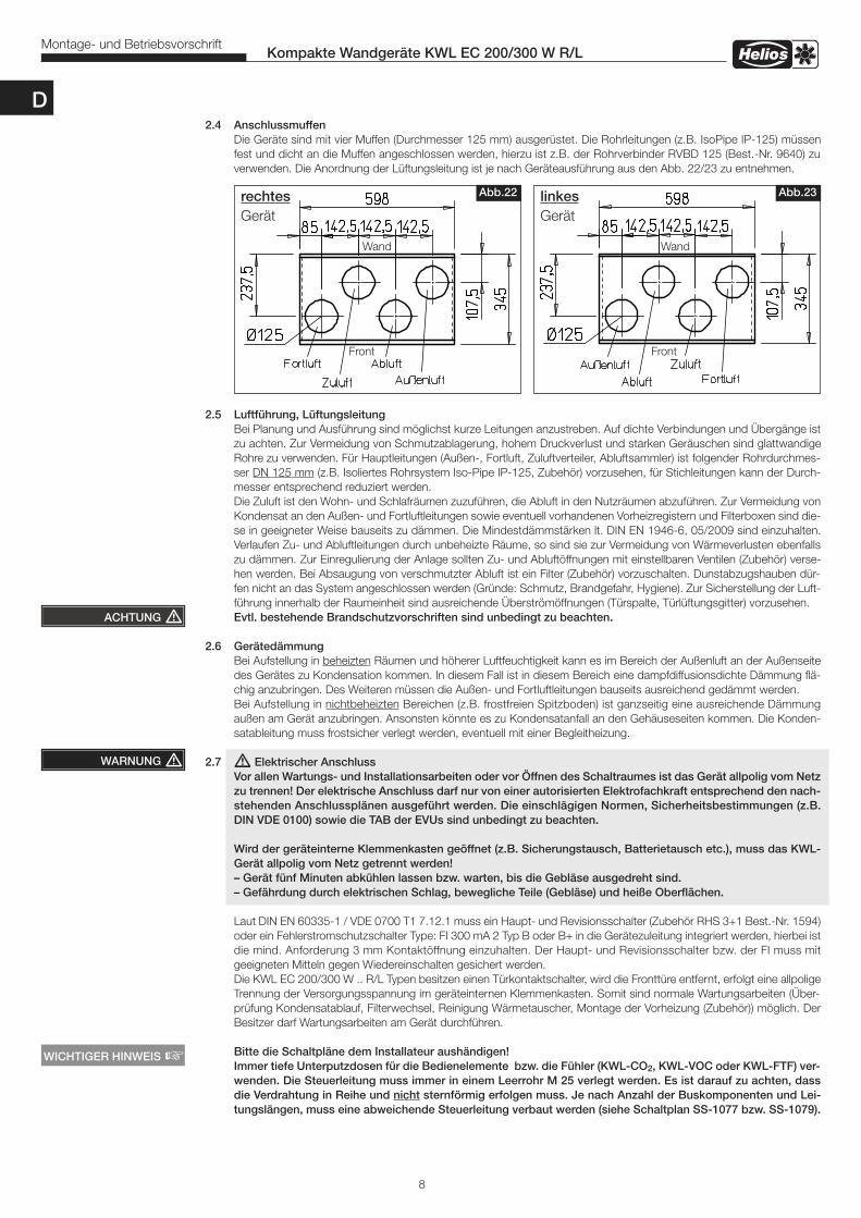
2.4 AnschlussmuffenDie Geräte sind mit vier Muffen (Durchmesser 125 mm) ausgerüstet. Die Rohrleitungen (z.B. IsoPipe IP-125) müssenfest und dicht an die Muffen angeschlossen werden, hierzu ist z.B. der Rohrverbinder RVBD 125 (Best.-Nr. 9640) zuverwenden. Die Anordnung der Lüftungsleitung ist je nach Geräteausführung aus den Abb. 22/23 zu entnehmen.
2.5 Luftführung, LüftungsleitungBei Planung und Ausführung sind möglichst kurze Leitungen anzustreben. Auf dichte Verbindungen und Übergänge istzu achten. Zur Vermeidung von Schmutzablagerung, hohem Druckverlust und starken Geräuschen sind glattwandigeRohre zu verwenden. Für Hauptleitungen (Außen-, Fortluft, Zuluftverteiler, Abluftsammler) ist folgender Rohrdurchmes-ser DN 125 mm (z.B. Isoliertes Rohrsystem Iso-Pipe IP-125, Zubehör) vorzusehen, für Stichleitungen kann der Durch-messer entsprechend reduziert werden.Die Zuluft ist den Wohn- und Schlafräumen zuzuführen, die Abluft in den Nutzräumen abzuführen. Zur Vermeidung vonKondensat an den Außen- und Fortluftleitungen sowie eventuell vorhandenen Vorheizregistern und Filterboxen sind die-se in geeigneter Weise bauseits zu dämmen. Die Mindestdämmstärken lt. DIN EN 1946-6, 05/2009 sind einzuhalten.Verlaufen Zu- und Abluftleitungen durch unbeheizte Räume, so sind sie zur Vermeidung von Wärmeverlusten ebenfallszu dämmen. Zur Einregulierung der Anlage sollten Zu- und Abluftöffnungen mit einstellbaren Ventilen (Zubehör) verse-hen werden. Bei Absaugung von verschmutzter Abluft ist ein Filter (Zubehör) vorzuschalten. Dunstabzugshauben dür-fen nicht an das System angeschlossen werden (Gründe: Schmutz, Brandgefahr, Hygiene). Zur Sicherstellung der Luft-führung innerhalb der Raumeinheit sind ausreichende Überströmöffnungen (Türspalte, Türlüftungsgitter) vorzusehen.Evtl. bestehende Brandschutzvorschriften sind unbedingt zu beachten.
2.6 GerätedämmungBei Aufstellung in beheizten Räumen und höherer Luftfeuchtigkeit kann es im Bereich der Außenluft an der Außenseitedes Gerätes zu Kondensation kommen. In diesem Fall ist in diesem Bereich eine dampfdiffusionsdichte Dämmung flä-chig anzubringen. Des Weiteren müssen die Außen- und Fortluftleitungen bauseits ausreichend gedämmt werden. Bei Aufstellung in nichtbeheizten Bereichen (z.B. frostfreien Spitzboden) ist ganzseitig eine ausreichende Dämmungaußen am Gerät anzubringen. Ansonsten könnte es zu Kondensatanfall an den Gehäuseseiten kommen. Die Konden-satableitung muss frostsicher verlegt werden, eventuell mit einer Begleitheizung.
2.7 � Elektrischer AnschlussVor allen Wartungs- und Installationsarbeiten oder vor Öffnen des Schaltraumes ist das Gerät allpolig vom Netzzu trennen! Der elektrische Anschluss darf nur von einer autorisierten Elektrofachkraft entsprechend den nach-stehenden Anschlussplänen ausgeführt werden. Die einschlägigen Normen, Sicherheitsbestimmungen (z.B.DIN VDE 0100) sowie die TAB der EVUs sind unbedingt zu beachten.
Wird der geräteinterne Klemmenkasten geöffnet (z.B. Sicherungstausch, Batterietausch etc.), muss das KWL-Gerät allpolig vom Netz getrennt werden!
– Gerät fünf Minuten abkühlen lassen bzw. warten, bis die Gebläse ausgedreht sind. – Gefährdung durch elektrischen Schlag, bewegliche Teile (Gebläse) und heiße Oberflächen.
Laut DIN EN 60335-1 / VDE 0700 T1 7.12.1 muss ein Haupt- und Revisionsschalter (Zubehör RHS 3+1 Best.-Nr. 1594) oder ein Fehlerstromschutzschalter Type: FI 300 mA 2 Typ B oder B+ in die Gerätezuleitung integriert werden, hierbei ist die mind. Anforderung 3 mm Kontaktöffnung einzuhalten. Der Haupt- und Revisionsschalter bzw. der FI muss mit geeigneten Mitteln gegen Wiedereinschalten gesichert werden.
Die KWL EC 200/300 W .. R/L Typen besitzen einen Türkontaktschalter, wird die Fronttüre entfernt, erfolgt eine allpoligeTrennung der Versorgungsspannung im geräteinternen Klemmenkasten. Somit sind normale Wartungsarbeiten (Über-prüfung Kondensatablauf, Filterwechsel, Reinigung Wärmetauscher, Montage der Vorheizung (Zubehör)) möglich. DerBesitzer darf Wartungsarbeiten am Gerät durchführen.
Bitte die Schaltpläne dem Installateur aushändigen! Immer tiefe Unterputzdosen für die Bedienelemente bzw. die Fühler (KWL-CO2, KWL-VOC oder KWL-FTF) ver-wenden. Die Steuerleitung muss immer in einem Leerrohr M 25 verlegt werden. Es ist darauf zu achten, dassdie Verdrahtung in Reihe und nicht sternförmig erfolgen muss. Je nach Anzahl der Buskomponenten und Lei-tungslängen, muss eine abweichende Steuerleitung verbaut werden (siehe Schaltplan SS-1077 bzw. SS-1079).
8
Kompakte Wandgeräte KWL EC 200/300 W R/LMontage- und Betriebsvorschrift
WARNUNG �
rechtesGerät
linkesGerät
Abb.22 Abb.23
Wand Wand
Front
ACHTUNG �
Front
WICHTIGER HINWEIS �
D
TIPP!TIPP!
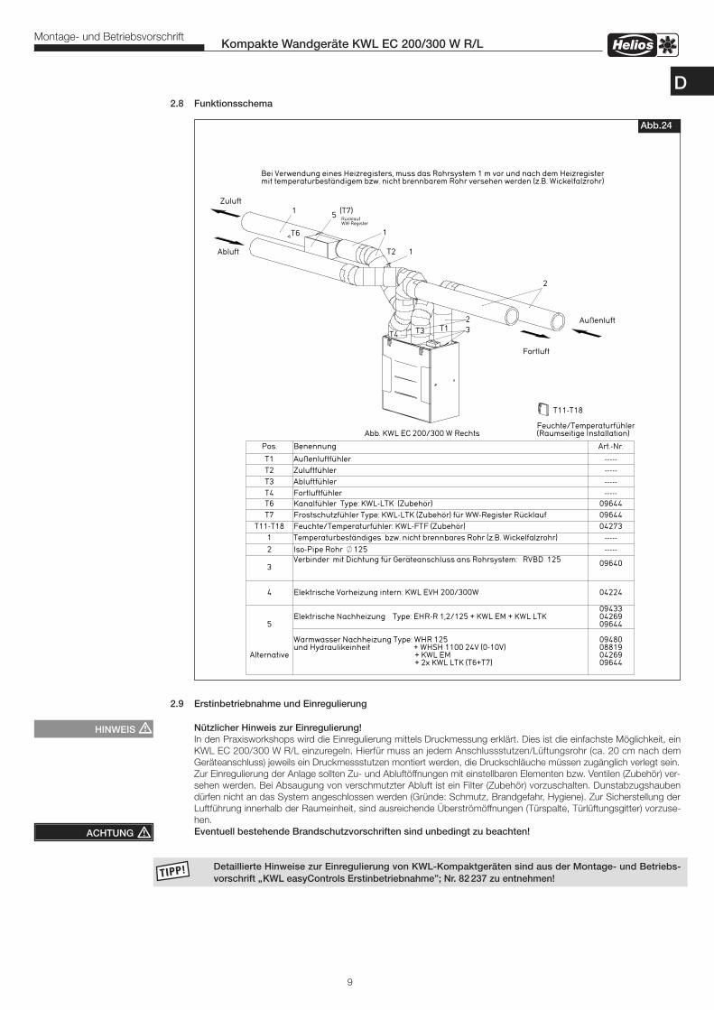
2.8 Funktionsschema
2.9 Erstinbetriebnahme und Einregulierung
Nützlicher Hinweis zur Einregulierung!In den Praxisworkshops wird die Einregulierung mittels Druckmessung erklärt. Dies ist die einfachste Möglichkeit, einKWL EC 200/300 W R/L einzuregeln. Hierfür muss an jedem Anschlussstutzen/Lüftungsrohr (ca. 20 cm nach demGeräteanschluss) jeweils ein Druckmessstutzen montiert werden, die Druckschläuche müssen zugänglich verlegt sein. Zur Einregulierung der Anlage sollten Zu- und Abluftöffnungen mit einstellbaren Elementen bzw. Ventilen (Zubehör) ver-sehen werden. Bei Absaugung von verschmutzter Abluft ist ein Filter (Zubehör) vorzuschalten. Dunstabzugshaubendürfen nicht an das System angeschlossen werden (Gründe: Schmutz, Brandgefahr, Hygiene). Zur Sicherstellung derLuftführung innerhalb der Raumeinheit, sind ausreichende Überströmöffnungen (Türspalte, Türlüftungsgitter) vorzuse-hen. Eventuell bestehende Brandschutzvorschriften sind unbedingt zu beachten!
Detaillierte Hinweise zur Einregulierung von KWL-Kompaktgeräten sind aus der Montage- und Betriebs- vorschrift „KWL easyControls Erstinbetriebnahme”; Nr. 82237 zu entnehmen!
9
Kompakte Wandgeräte KWL EC 200/300 W R/LMontage- und Betriebsvorschrift
Abb.24
ACHTUNG �
HINWEIS �
D
3.0 Service und Wartung � Vor allen Wartungs- und Installationsarbeiten oder vor Öffnen des Schaltraumes ist das Gerät allpolig vom Netz zu trennen! – Gerät fünf Minuten abkühlen lassen bzw. warten, bis die Gebläse ausgedreht sind. – Gefährdung durch elektrischen Schlag, bewegliche Teile (Gebläse) und heiße Oberflächen.
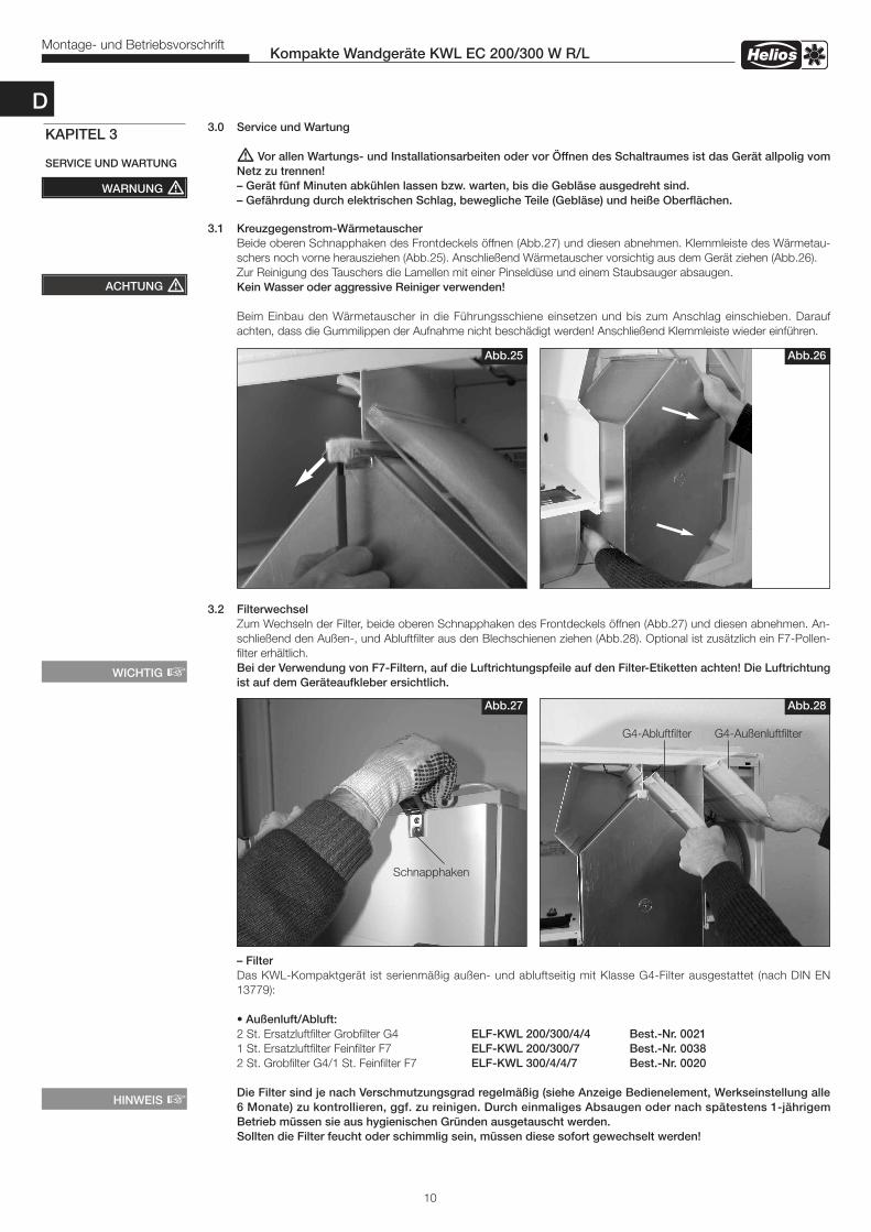
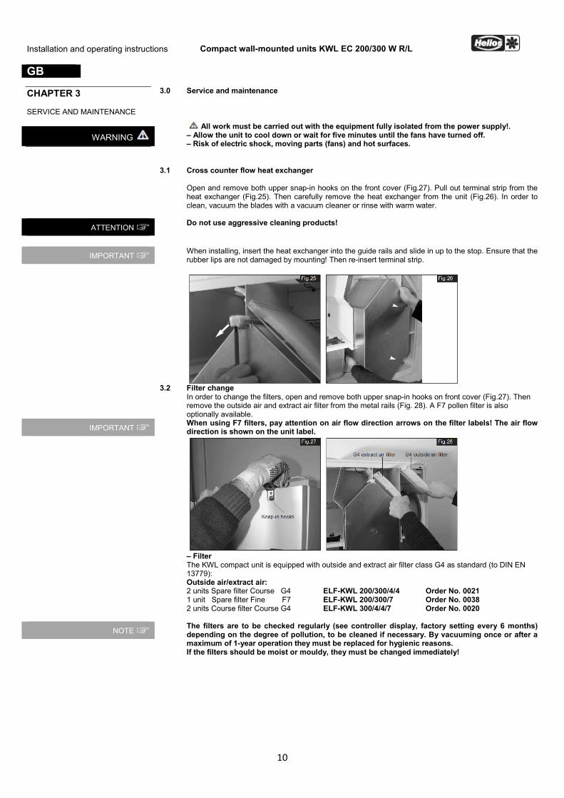
3.1 Kreuzgegenstrom-Wärmetauscher Beide oberen Schnapphaken des Frontdeckels öffnen (Abb.27) und diesen abnehmen. Klemmleiste des Wärmetau- schers noch vorne herausziehen (Abb.25). Anschließend Wärmetauscher vorsichtig aus dem Gerät ziehen (Abb.26). Zur Reinigung des Tauschers die Lamellen mit einer Pinseldüse und einem Staubsauger absaugen. Kein Wasser oder aggressive Reiniger verwenden! Beim Einbau den Wärmetauscher in die Führungsschiene einsetzen und bis zum Anschlag einschieben. Darauf achten, dass die Gummilippen der Aufnahme nicht beschädigt werden! Anschließend Klemmleiste wieder einführen.
3.2 Filterwechsel Zum Wechseln der Filter, beide oberen Schnapphaken des Frontdeckels öffnen (Abb.27) und diesen abnehmen. An- schließend den Außen-, und Abluftfilter aus den Blechschienen ziehen (Abb.28). Optional ist zusätzlich ein F7-Pollen- filter erhältlich. Bei der Verwendung von F7-Filtern, auf die Luftrichtungspfeile auf den Filter-Etiketten achten! Die Luftrichtung ist auf dem Geräteaufkleber ersichtlich.
– Filter Das KWL-Kompaktgerät ist serienmäßig außen- und abluftseitig mit Klasse G4-Filter ausgestattet (nach DIN EN 13779): • Außenluft/Abluft: 2 St. Ersatzluftfilter Grobfilter G4 ELF-KWL 200/300/4/4 Best.-Nr. 0021 1 St. Ersatzluftfilter Feinfilter F7 ELF-KWL 200/300/7 Best.-Nr. 0038 2 St. Grobfilter G4/1 St. Feinfilter F7 ELF-KWL 300/4/4/7 Best.-Nr. 0020 Die Filter sind je nach Verschmutzungsgrad regelmäßig (siehe Anzeige Bedienelement, Werkseinstellung alle 6 Monate) zu kontrollieren, ggf. zu reinigen. Durch einmaliges Absaugen oder nach spätestens 1-jährigem Betrieb müssen sie aus hygienischen Gründen ausgetauscht werden. Sollten die Filter feucht oder schimmlig sein, müssen diese sofort gewechselt werden!
Abb.27 Abb.28
Schnapphaken
HINWEIS �
G4-Außenluftfilter
10
Kompakte Wandgeräte KWL EC 200/300 W R/LMontage- und Betriebsvorschrift
WARNUNG �
KAPITEL 3
SERVICE UND WARTUNG
Abb.25 Abb.26
WICHTIG �
G4-Abluftfilter
ACHTUNG �
D

3.3 Kondensatablauf im Gerät Bei Wartungsmaßnahmen sicherstellen, dass der Kugelsiphon in der Bodenwanne des Gerätes nicht verstopft ist (Punkt 2.2). Dies kann durch Eingießen einer kleinen Menge Wasser in den Siphon überprüft werden. Hierbei darf kein Wasser in elektrische Teile gelangen! Die Überprüfung bzw. Reinigung des Kondensatablaufs muss jährlich erfolgen!
� Die Arbeiten nur mit EMV-Schutz durchführen, da sonst ein EMV-Schaden auftreten kann!
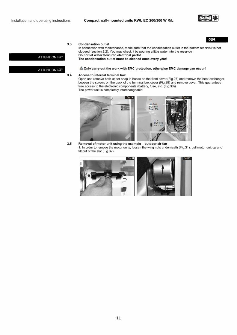
3.4 Zugang zum interner Klemmenkasten Beide oberen Schnapphaken des Frontdeckels öffnen (Abb.27) und diesen abnehmen und Wärmetauscher demontie- ren. Schrauben der Klemmenkastenabdeckung an der Rückseite lösen (Abb.29) und Abdeckung entfernen. Somit ist ein freier Zugang zu den elektronischen Bauteilen (Batterie, Sicherung etc. (Abb.30)) gewährleistet. Die Leistungseinheit ist komplett austauschbar!
3.5 Demontage Motoreinheit am Beispiel - Außenluftgebläse -1. Zur Demontage der Motoreinheiten unterhalb Flügelmutter lösen (Abb.31), Motoreinheit nach oben ziehen und ausdem Gebläseschacht kippen (Abb.32).
11
Kompakte Wandgeräte KWL EC 200/300 W R/LMontage- und Betriebsvorschrift
Abb.30Abb.29
ACHTUNG �
Abb.32Abb.31
Leistungseinheit
ACHTUNG �
Feinsicherung5x20 mmT4A / 250
Sicherung5x20 mmF2A / 250
Batterie
D

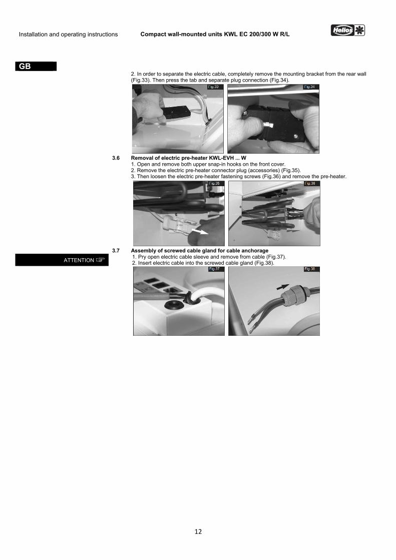
2. Zum Trennen des Elektrokabels die Halterung komplett von der Rückwand abziehen (Abb.33). Anschließend Verschluss drücken und Steckverbindung trennen (Abb.34).
3.6 Demontage Elektro-Vorheizung KWL-EVH ... W 1. Beide oberen Schnapphaken des Frontdeckels öffnen und diesen abnehmen. 2. Anschlussstecker der Elektro-Vorheizung (Zubehör) abziehen (Abb.35). 3. Anschließend Befestigungsschraube der Elektro-Vorheizung lösen (Abb.36) und Vorheizung entnehmen.
3.7 Montage der Kabelverschraubung zur Zugentlastung 1. Kabeltülle des Elektrokabels aufhebeln und vom Kabel abziehen (Abb.37). 2. Elektrokabel in die Kabelverschraubung einführen (Abb.38).
Abb.35 Abb.36
12
Kompakte Wandgeräte KWL EC 200/300 W R/LMontage- und Betriebsvorschrift
Abb.33 Abb.34
HINWEIS �
Abb.37 Abb.38
ACHTUNG �
D
13
Kompakte Wandgeräte KWL EC 200/300 W R/LMontage- und Betriebsvorschrift
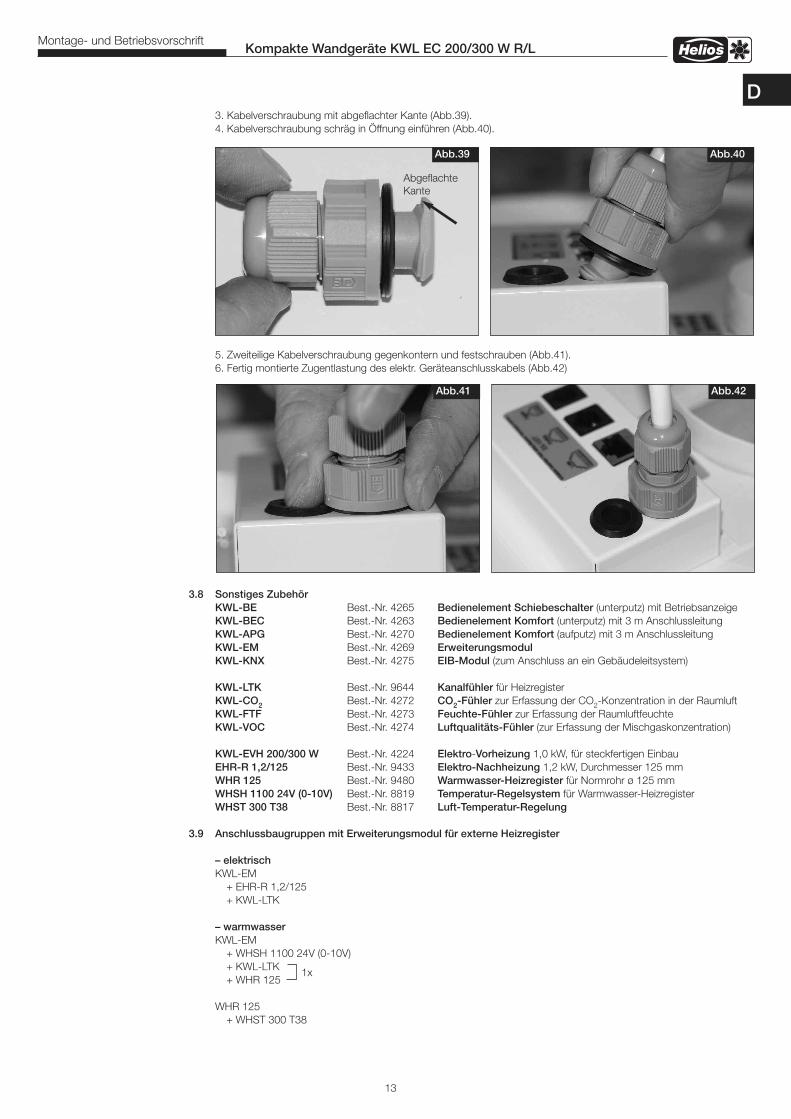
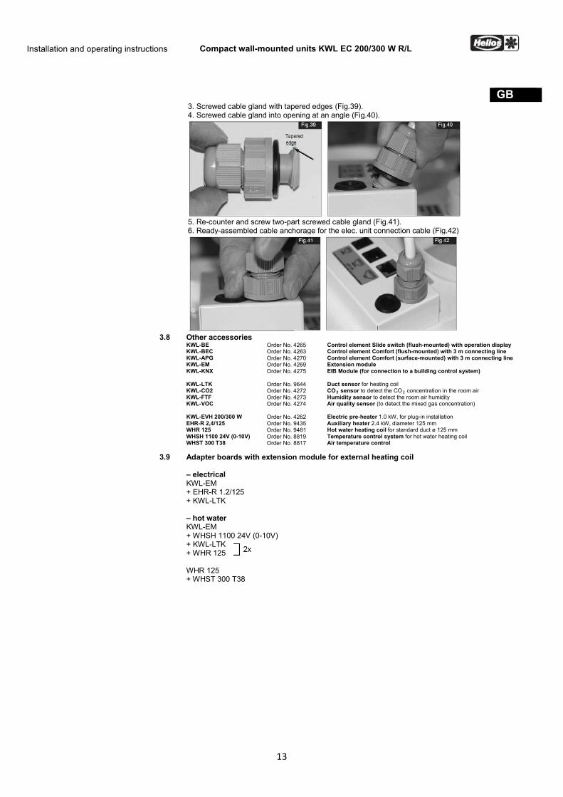
3. Kabelverschraubung mit abgeflachter Kante (Abb.39). 4. Kabelverschraubung schräg in Öffnung einführen (Abb.40).
5. Zweiteilige Kabelverschraubung gegenkontern und festschrauben (Abb.41). 6. Fertig montierte Zugentlastung des elektr. Geräteanschlusskabels (Abb.42)
3.8 Sonstiges Zubehör KWL-BE Best.-Nr. 4265 Bedienelement Schiebeschalter (unterputz) mit Betriebsanzeige KWL-BEC Best.-Nr. 4263 Bedienelement Komfort (unterputz) mit 3 m Anschlussleitung KWL-APG Best.-Nr. 4270 Bedienelement Komfort (aufputz) mit 3 m Anschlussleitung KWL-EM Best.-Nr. 4269 Erweiterungsmodul KWL-KNX Best.-Nr. 4275 EIB-Modul (zum Anschluss an ein Gebäudeleitsystem)
KWL-LTK Best.-Nr. 9644 Kanalfühler für Heizregister KWL-CO2 Best.-Nr. 4272 CO2-Fühler zur Erfassung der CO2-Konzentration in der Raumluft KWL-FTF Best.-Nr. 4273 Feuchte-Fühler zur Erfassung der Raumluftfeuchte KWL-VOC Best.-Nr. 4274 Luftqualitäts-Fühler (zur Erfassung der Mischgaskonzentration)
KWL-EVH 200/300 W Best.-Nr. 4224 Elektro-Vorheizung 1,0 kW, für steckfertigen Einbau EHR-R 1,2/125 Best.-Nr. 9433 Elektro-Nachheizung 1,2 kW, Durchmesser 125 mm WHR 125 Best.-Nr. 9480 Warmwasser-Heizregister für Normrohr ø 125 mm WHSH 1100 24V (0-10V) Best.-Nr. 8819 Temperatur-Regelsystem für Warmwasser-Heizregister WHST 300 T38 Best.-Nr. 8817 Luft-Temperatur-Regelung
3.9 Anschlussbaugruppen mit Erweiterungsmodul für externe Heizregister
– elektrisch KWL-EM + EHR-R 1,2/125 + KWL-LTK
– warmwasser KWL-EM + WHSH 1100 24V (0-10V) + KWL-LTK + WHR 125
WHR 125 + WHST 300 T38
Abb.39 Abb.40
Abb.41 Abb.42
AbgeflachteKante
1x
D
14
Kompakte Wandgeräte KWL EC 200/300 W R/LMontage- und Betriebsvorschrift
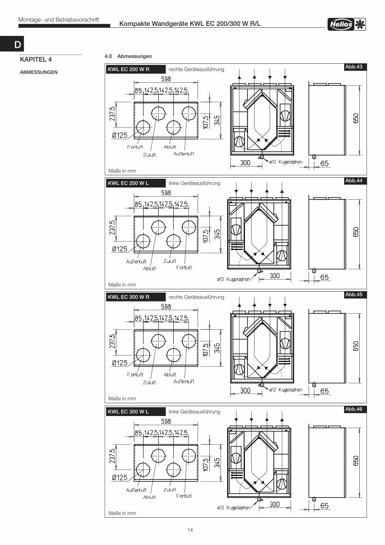
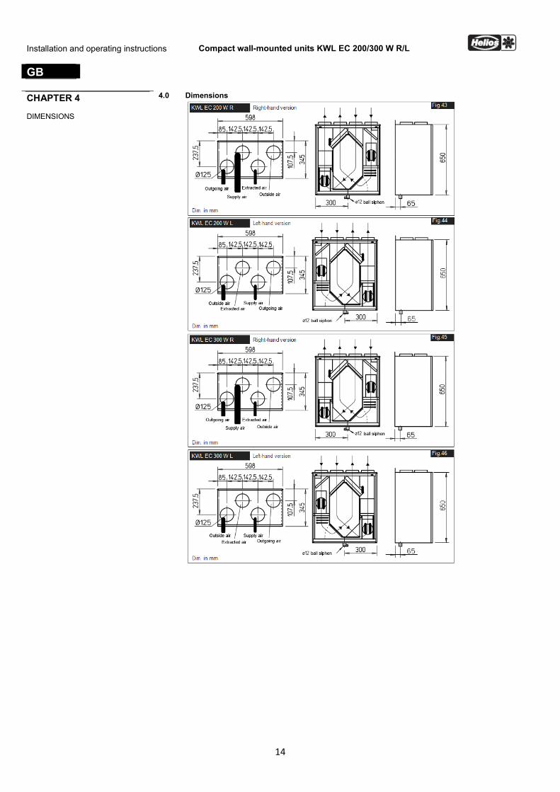
Maße in mm
KWL EC 200 W R rechte Geräteausführung Abb.43
4.0 AbmessungenKAPITEL 4
ABMESSUNGEN
Maße in mm
KWL EC 200 W L linke Geräteausführung Abb.44
Maße in mm
KWL EC 300 W R rechte Geräteausführung Abb.45
Maße in mm
KWL EC 300 W L linke Geräteausführung Abb.46
D
15
Kompakte Wandgeräte KWL EC 200/300 W R/LMontage- und Betriebsvorschrift
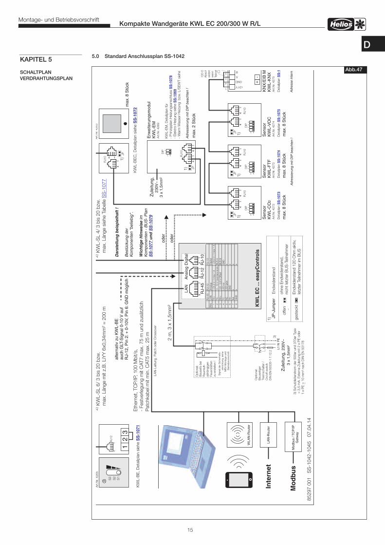
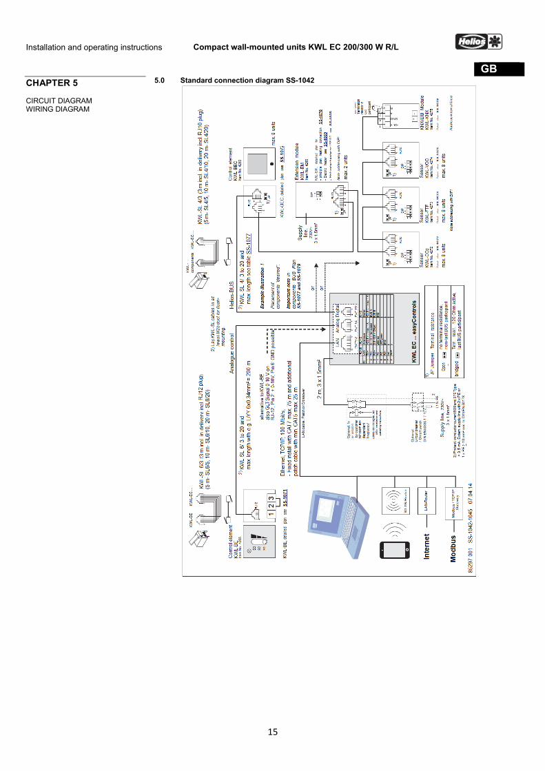
5.0 Standard Anschlussplan SS-1042
Abb.47
KAPITEL 5
SCHALTPLANVERDRAHTUNGSPLAN
D
16
Kompakte Wandgeräte KWL EC 200/300 W R/LMontage- und Betriebsvorschrift
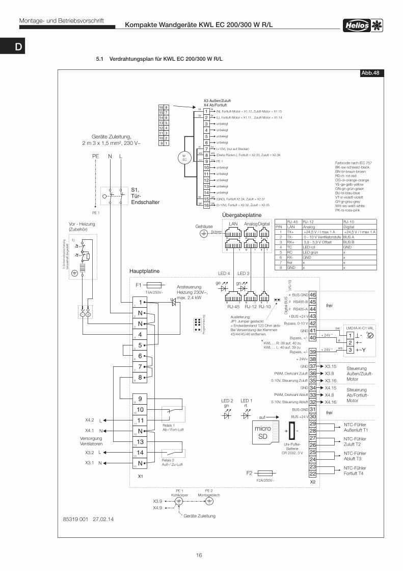
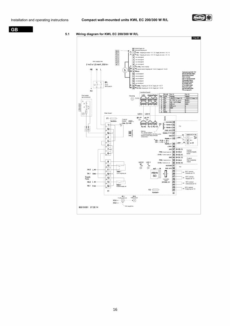
5.1 Verdrahtungsplan für KWL EC 200/300 W R/L
Abb.48
D
17
Kompakte Wandgeräte KWL EC 200/300 W R/LMontage- und Betriebsvorschrift
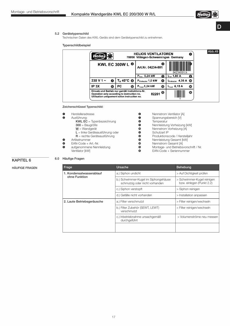
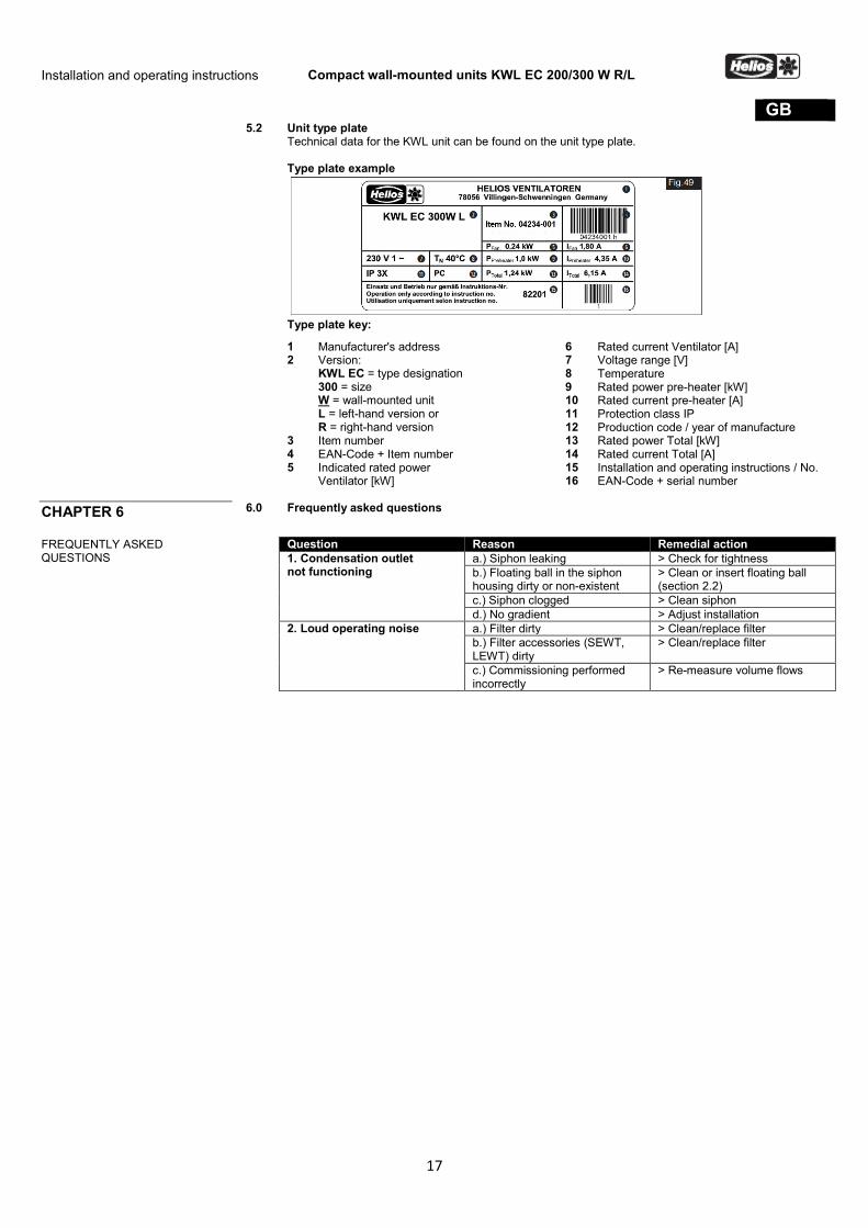
5.2 Gerätetypenschild Technischen Daten des KWL-Geräts sind dem Gerätetypenschild zu entnehmen.
Typenschildbeispiel
Zeichenschlüssel Typenschild:
q Herstelleradresse y Nennstrom Ventilator [A]w Ausführung: u Spannungsbereich [V] KWL EC = Typenbezeichnung i Temperatur 300 = Baugröße o Nennleistung Vorheizung [kW] W = Wandgerät a Nennstrom Vorheizung [A] L = linke Geräteausführung oder s Schutzart IP R = rechte Geräteausführung d Produktionscode / Herstelljahre Artikelnummer f Nennleistung Gesamt [kW]r EAN-Code + Art.-Nr. g Nennstrom Gesamt [A]t aufgenommene Nennleistung h Montage- und Betriebsvorschrift / Nr. Ventilator [kW] j EAN-Code + Seriennummer
6.0 Häufige FragenKAPITEL 6
HÄUFIGE FRAGEN Frage Ursache Behebung
1. Kondensatwasserablauf ohne Funktion
a.) Siphon undicht > Auf Dichtigkeit prüfen
b.) Schwimmer-Kugel im Siphongehäuse schmutzig oder nicht vorhanden
> Schwimmer-Kugel reinigen bzw. einlegen (Punkt 2.2)
c.) Siphon verstopft > Siphon reinigen
d.) Gefälle nicht vorhanden > Installation anpassen
2. Laute Betriebsgeräusche a.) Filter verschmutzt > Filter reinigen/wechseln
b.) Filter Zubehör (SEWT, LEWT) verschmutzt
> Filter reinigen/wechseln
c.) Inbetriebnahme unsachgemäßdurchgeführt
> Volumenströme neu messen
Abb.49q
w e r
u it yo a
s d f g
h j
D

Service und InformationD HELIOS Ventilatoren GmbH + Co KG · Lupfenstraße 8 · 78056 VS-Schwenningen F HELIOS Ventilateurs · Le Carré des Aviateurs · 157 avenue Charles Floquet · 93155 Le Blanc Mesnil CedexCH HELIOS Ventilatoren AG · Tannstrasse 4 · 8112 Otelfingen GB HELIOS Ventilation Systems Ltd. · 5 Crown Gate · Wyncolls Road · Severalls Industrial Park · A HELIOS Ventilatoren · Postfach 854 · Siemensstraße 15 · 6023 Innsbruck Colchester · Essex · CO4 9HZ
www.heliosventilatoren.deAlle Abbildungen ohne Gewähr!Als Referenz am Gerät griffbereit aufbewahren! Druckschrift-Nr. 82201/11.14
Helios Ventilation Systems INSTALLATION AND OPERATING INSTRUCTIONS
No. 82 201
GB
Compact wall-mounted units with easyControls
KWL EC 200 W R/L KWL EC 300 W R/L
- heat recovery and EC technology for central ventilation
ENGLISH INSTALLATION AND OPERATING INSTRUCTIONS
Table of Contents CHAPTER 1. GENERAL INSTALLATION AND OPERATING INSTRUCTIONS Page 1 1.0
1.1 1.2 1.3 1.4 1.5 1.6 1.7 1.8 1.9 1.10 1.11 1.12 1.13
General information Warning and safety instructions Important technical information Guarantee and liability claims Certificates - guidelines Receipt Storage Shipping Application – Operation Mode of operation Performance data Fire places Technical data RJ connections for control concept
Page 1 Page 1 Page 1 Page 1 Page 1 Page 1 Page 1 Page 1 Page 2 Page 2 Page 2 Page 2 Page 3 Page 3
CHAPTER 2. INSTALLATION Page 4 2.0
2.1 2.2 2.3 2.4 2.5 2.6 2.7 2.8 2.9
Assembly Wall installation Condensation outlet Installation of electric pre-heater KWL-EVH ... W (Accessories) Connecting spigots Air ducting, ventilation circuit Unit insulation Electrical connection Functional layout Initial start-up and adjustment
Page 4 Page 4 Page 5 Page 7 Page 8 Page 8 Page 8 Page 8 Page 9 Page 9
CHAPTER 3. SERVICE AND MAINTENANCE Page 10 3.0
3.1 3.2 3.3 3.4 3.5 3.6 3.7 3.8 3.9
Service and maintenance Cross counter flow heat exchanger Filter change Condensation outlet on the unit Access to internal terminal box Removal of supply fan Removal of electric pre-heater Assembly of screwed cable gland for cable anchorage Other accessories Adapter boards
Page 10 Page 10 Page 10 Page 11 Page 11 Page 11 Page 12 Page 12 Page 13 Page 13
CHAPTER 4. DIMENSIONS Page 14 4.0 Dimensions
Page 14
CHAPTER 5. DIMENSIONS Page 15 5.0
5.1 5.2
Standard connection diagram SS-1042 Wiring diagram KWL EC 200/300 W R/L Motor type plate
Page 15 Page 16 Page 17
CHAPTER 6. FREQUENTLY ASKED QUESTIONS 6.0 Frequently asked questions
Page 17
This product contains batteries or accumulators. According to the German Battery Act (BattG), we are obliged to point out the following: Batteries and accumulators must not be disposed of in household waste. You are legally obligated to return used batteries and accumulators. You can return batteries to a community collection point or return them to the place where you bought them free of charge. Batteries or accumulators that contain harmful substances are labelled with the symbol of a crossed-out waste bin. The chemical symbol of the harmful substance is specified below the waste bin symbol. Cd for Cadmium, Pb for Lead and Hg for Mercury Please think of the environment, you can make a significant contribution to environmental protection by returning batteries and accumulators!
Installation and operating instructions Compact wall-mounted units KWL EC 200/300 W R/L
1
GB Congratulations You have chosen a product from Helios Ventilation Systems. This means that you have purchased a premium product and you will benefit from our many years of experience. All KWL EC 200/300 W R/L units have been tested at every stage of production. Not only has the obvious function (e.g. the fans running) been tested, but also the functions which you, as the customer, cannot test. For example, these include internal and external leakages and electrical safety. We enable you to reduce operating costs through innovative ideas in the field of control and feedback control systems. We achieve this through intelligent frost protection strategies, which only become active if the performance of the heat exchanger is affected. However, if you unexpectedly have a problem with our unit, you can contact the specialist installer or our Helios customer service team. CHAPTER 1 GENERAL INSTALLATION AND OPERATING INSTRIUCTIONS
1.0 General information To ensure safety and correct operation please, read and observe the following instructions carefully before proceeding. All relevant national standards, safety regulations and provisions (e.g. DIN EN VDE 0100) and the technical connection conditions of the electrical supply company must be observed and applied. The planning office provides the planning documents necessary for the system calculation. Additional information or a detailed plan (chargeable service) can be requested from Helios. Keep the installation and operating instructions as a reference at the device. After the final assembly, the document must be handed to the operator (tenant/owner). Outline of the installation and operating instructions: Chapters 1 – 3 General installation, operating instructions, unit installation and initial start-up and adjustment
– intended for specialist installers Chapters 4 – 5 Accessories + Service and Maintenance
– intended for specialist installers and end customers All information on the operation and control of the compact unit can be found in the “easyControls” operating instructions (No. 82 200), which is included in the delivery. These operating instructions are intended for specialist installers and end customers.
1.1 Warning and safety instructions
The accompanying symbol is a safety-relevant prominent warning symbol. All safety regulations and/or symbols must be absolutely adhered to, so that any dangerous situation is avoided.
1.2
Important technical information The KWL EC 200/300 W R/L has a door contact switch. If the front door is removed, the internal terminal box is fully isolated from the power supply. In this way, normal maintenance work e.g.: checking the condensation outlet, filter change, heat exchanger cleaning, installation of the pre-heater (accessories) is possible.
IMPORTANT ☞
ATTENTION The internal terminal box may only be opened by an authorised electrical expert! The appropriate
measures can be found in Chapter 2.
1.3 Guarantee and liability claims In order to safeguard the guarantee and liability claims of the customer, the following information must be observed: – Implementation according to “unit” Installation and operating instructions – Implementation according to “easyControls” operating instructions – The use of accessories, which are not approved, recommended or offered by Helios, is not permissible. Any damages are excluded from the guarantee. If these instructions are not observed, all warranty claims and accommodation treatment are excluded. This also applies to any liability claims extended to the manufacturer.
1.4 Certificates - guidelines If the product is installed correctly and used to its intended purpose, it conforms to all applicable European Standards at its date of manufacture.
1.5 Receipt The delivery contains the unit: KWL EC 200 W R/L or the unit: KWL EC 300 W R/L Please check delivery immediately on receipt for accuracy and damage. If damaged, please notify the carrier immediately. In case of delayed notification, any possible claim may be void.
1.6 Storage When storing for a prolonged time, the following steps are to be taken to avoid damaging influences: Protection by dry, air-dustproof packing (plastic bags with drying agent and moisture indicators). The storage place must be waterproof, vibration-free and free of temperature variations. Damages due to improper transportation, storage or putting into operation are not liable for warranty.
1.7 Shipping The unit is packed ex works in such a way that it is protected against normal transport strain. Carry out the shipping carefully. It is recommended to leave the unit in the original packaging until installation to avoid possible damages and soiling.
Installation and operating instructions Compact wall-mounted units KWL EC 200/300 W R/L
2
GB
1.8 Application – Operation KWL EC 200/300 W R/L compact units with heat recovery are suitable for the central ventilation of houses and apartments. Equipped with easyControls, the innovative control concept for simpler network connection and web browser operation. Equipped with a highly efficient plastic cross counter flow heat exchanger with a heat recovery efficiency of , see chart:
Unit type Target flow rate [m³/h] 120 168 251
KWL EC 200 W R/L Heat recovery efficiency of up to 90 % 85 % 84 %
KWL EC 300 W R/L Heat recovery efficiency of up to 90 % 85 % 84 %
The standard equipment permits the installation and the application in frost-free rooms > + 5 °C. If the unit is to be used in other applications where high humidity, excessive dust, temperature in excess of 40 °C or long periods at standstill (not running), please contact your local Helios dealer for advice. This also applies for special technical and electrical applications.
IMPORTANT ☞ The ventilation unit must only be used according to its intended purpose!
1.9 Mode of operation The KWL compact unit has a plastic cross counter flow heat exchanger, in which the outside air (fresh air) crosses the extract building air, without coming into contact with each other. Through this procedure more than 85 % of the extract air heat is transferred to the external air. The supply air is led by the duct system to the primary (supply air needing) areas. The used air is extracted from the secondary areas (e.g. social rooms, toilets, showers etc.). It flows back through the ducting to the ventilation unit, transfers the heat and is discharged by the extract air duct into the atmosphere. The efficiency depends on several factors. These are, among other things, the humidity of the air and the temperature difference of the outside air and extract air. The volume flow can be regulated via the local web server (included in the delivery). In addition, the KWL unit can also be operated via accessories. Two control elements are available: KWL-BE and KWL-BEC. Demand-based regulation can take place through the optional sensors KWL-VOC = air quality sensor, KWL-CO2 = carbon dioxide sensor or KWL-FTF = humidity and temperature sensor or through the integrated weekly timer. The electric pre-heater KWL-EVH … W (accessories, Order No. 4224) heats the outside air at very low outside temperatures, and thus prevents the heat exchanger from freezing and guarantees its safe function and optimum heat recovery, even in winter. The supply air can also be heated by activating a power-regulated, external electric or hot water auxiliary heater (accessories EHR-R... or WHR...). Another option is to cool the warmer outside air with the cooler unit extract air. The summer bypass is the optimum solution to conduct cooler outside air into the building during warm periods. The air is optimally pre-filtered through the integrated filter, which ensures a hygienic unit and simultaneously guarantees the durability of the KWL unit. A G4 filter (optional F7 pollen filter) is connected upstream from the outside air as standard and a G4 filter is connected upstream from the extract air.
TIP! Replacement air filters can be ordered online at www.ersatzluftfilter.de
1.10 Performance data In order to achieve the appropriate performance data (volume flow, sound, current consumption and max. pressure), ventilation must take place correctly (outside air/supply air and extract air/outgoing air). The ventilation duct must be dimensioned accordingly. The filters must also be replaced regularly to maintain optimum performance. The proper installation and adjustment of all components (units and peripheral devices) are extremely important.
TIP! Helios offers regular practical workshops on this topic; here you will find all the important details in a practical environment. The dates can be found on our website www.heliosventilatoren.de under training.
Deviating versions, unfavourable installation and operating conditions can lead to the reduction of output or an increased sound level. The figures for the air-side sound are recognised as A-weighted sound power level LWA (corresponds to DIN 45635, T.1). The figures in A-weighted sound pressure LPA are influenced by room and installation-specific factors. Accordingly, there are deviations in the figures.
1.11 Fireplaces The simultaneous use of controlled ventilation (KWL units) and room-air dependent fireplaces (tiled stove, gas-fired boiler, etc.), requires the observance of all applicable rules. In apartments, which are airtight according to the state of technology, a room-air dependent fireplace may only be operated with a separate combustion air supply; KWL units and fireplaces can only be operated based on demand when they are decoupled. The relevant applicable rules for the joint operation of fireplaces, ventilation, extraction hoods (Federal Association of Chimney Sweeps (ZIV)) must be observed!
IMPORTANT ☞ – General building regulation requirements The KWL units with heat recovery can only be installed and operated in rooms with other room air-dependent fireplaces if the exhaust duct is monitored by special safety devices (by client), which switch off the KWL unit when activated. The KWL unit will be switched off until the fireplace is no longer active. In the process, it is important to ensure that the underpressure does not exceed 4 Pa in the residential unit by operating the KWL unit.
Installation and operating instructions Compact wall-mounted units KWL EC 200/300 W R/L
3
GB The KWL unit must not be operated at the same time as solid fuel fireplaces and not in residential units
with room air-dependent fireplaces, which are connected to multiple exhaust systems. Any existing combustion air ducts and exhaust systems for solid fuel fireplaces must be capable of being shut off for the proper operation of the ventilation system established with a ventilation unit with heat recovery.
TIP! We recommend that you consult the responsible chimney sweep in order to accommodate your wishes before purchasing an underpressure monitoring system for fireplaces.
ATTENTION Monitoring systems are always integrated in the unit supply cable! (see circuit diagram SS-1042)
WARNING ATTENTION DANGER TO LIFE! The use of the external contact (function 1; enable/disable unit) of
the KWL-EM or the KWL-CO2 / KWL-VOC as a shutdown method for underpressure monitoring is not permissible.
1.12 Technical data
KWL EC 200 W R/L
Voltage/Frequency Rated current – ventilation Rated current – pre-heater Rated current – max. total Elec. pre-heater (outlet) kW Summer bypass Standby losses Electrical power feed to UV
1 ~ 230 V/50 Hz 1.0 A 4.4 A 1.0 A (5.4 incl. pre-heater, accessories) 1.0 kW (accessories) auto (adjustable), with exchanger cover Standby mode not possible NYM-J 3 x 1.5 mm2 ATTENTION! double earth connection
Air flow rates V m3/h (9 levels) Temperature operating range Installation area temperature Protection to Weight approx. Connection according to circuit diagram Cross counter flow heat exchanger
235 / … / 18 -20 °C to +40 °C +5 °C to +40 °C IP20 41 kg SS-1042 Plastic
KWL EC 300 W R/L Voltage/Frequency
Rated current – ventilation Rated current – pre-heater Rated current – max. total Elec. pre-heater (outlet) kW Summer bypass Standby losses Electrical power feed to UV
1 ~ 230 V/50 Hz 1.3 A 4.4 A 1.8 A (5.7 incl. pre-heater, accessories) 1.0 kW (accessories) auto (adjustable), with exchanger cover Standby mode not possible NYM-J 3 x 1.5 mm2 ATTENTION! double earth connection
Air flow rates V m3/h (9 levels) Temperature operating range Installation area temperature Protection to Weight approx. Connection according to circuit diagram Cross counter flow heat exchanger
315 / … / 55 -20 °C to +40 °C +5 °C to +40 °C IP20 42 kg SS-1042 Plastic
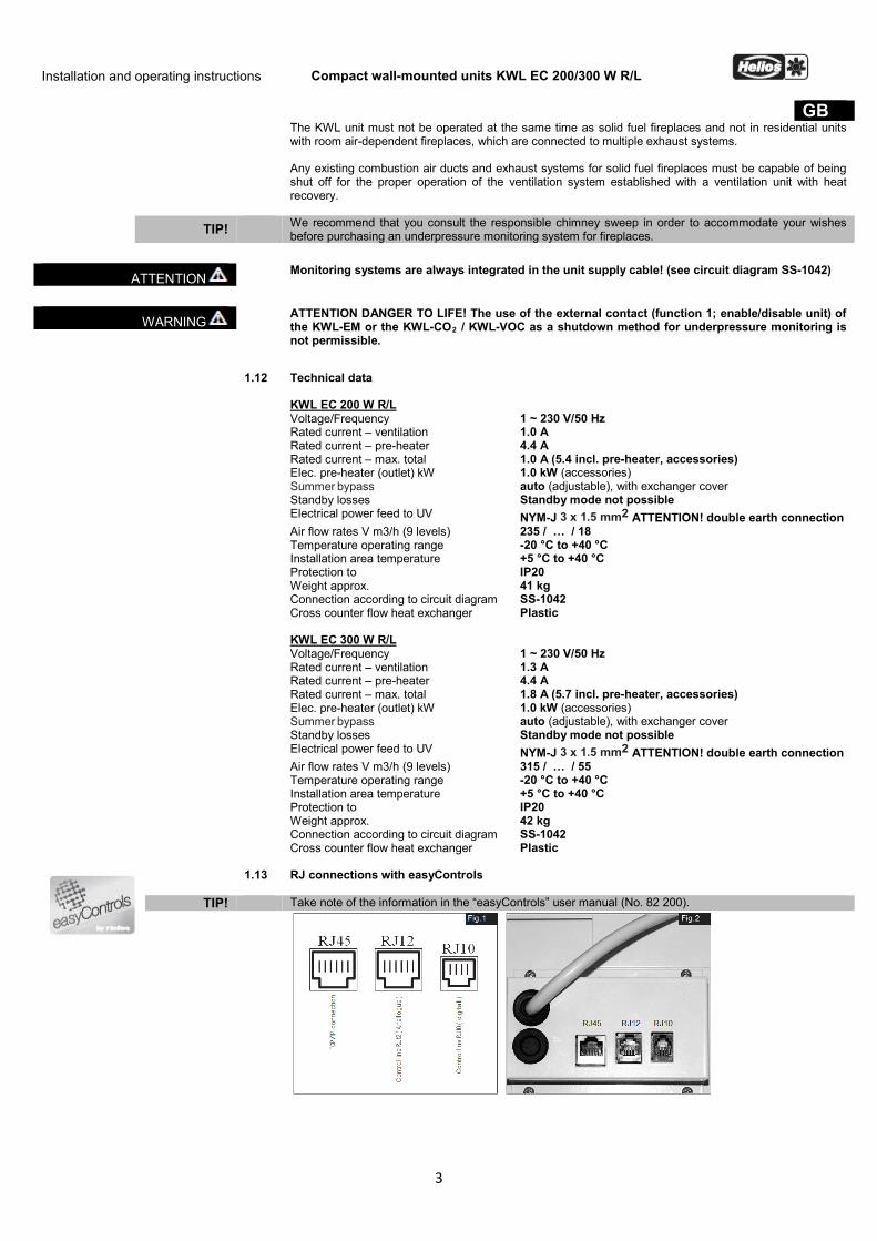
1.13 RJ connections with easyControls
TIP! Take note of the information in the “easyControls” user manual (No. 82 200).
Installation and operating instructions Compact wall-mounted units KWL EC 200/300 W R/L
4
GB
CHAPTER 2 INSTALLATION
2.0 Assembly The KWL compact unit is suitable for “hanging”, for wall installation and therefore intended for installation within a residential/room unit. Due to operating noises which change according to system pressure, it is recommended to install the KWL unit in the washing room, utility rooms or storerooms. Ensure that there is a waste water connection in the installation area. Please consider the information in section 2.2 "condensation outlet"! Installation should take place in such a way to enable preferably short ventilation ducts and their trouble-free connection to the unit. Tight bends can lead to increased pressure loss and flow noise.
IMPORTANT ☞ Important note: 1. Terminal box is accessible on the left side for the right-hand version, and on the right side for
the left-hand version. 2. If an additional external heater battery is installed, the duct must be at least 1 m before and after
the heater battery from non-flammable material (see functional layout Fig.24). 3. The heater must be installed in such a way that the electric box is easily accessible. 4. In order to avoid sound transmissions, a suitable acoustic insulation must be planned on site
depending upon the structure. 5. When installing the KWL compact unit, a sufficiently accessible revision area must be provided. 6. The installation of the KWL compact unit is permitted only in frost-protected areas, since the
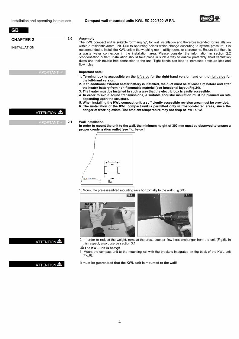
danger of freezing exists. The ambient temperature may not drop below +5 °C! ATTENTION
IMPORTANT ☞ 2.1 Wall installation
In order to mount the unit to the wall, the minimum height of 300 mm must be observed to ensure a proper condensation outlet (see Fig. below)!
1. Mount the pre-assembled mounting rails horizontally to the wall (Fig.3/4).
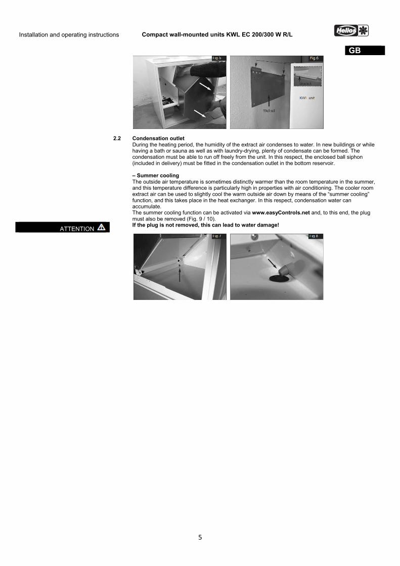
ATTENTION 2. In order to reduce the weight, remove the cross counter flow heat exchanger from the unit (Fig.5). In
this respect, also observe section 3.1. The KWL unit is heavy!
3. Mount the compact unit to the mounting rail with the brackets integrated on the back of the KWL unit (Fig.6).
ATTENTION It must be guaranteed that the KWL unit is mounted to the wall!
Installation and operating instructions Compact wall-mounted units KWL EC 200/300 W R/L
5
GB
2.2 Condensation outlet During the heating period, the humidity of the extract air condenses to water. In new buildings or while having a bath or sauna as well as with laundry-drying, plenty of condensate can be formed. The condensation must be able to run off freely from the unit. In this respect, the enclosed ball siphon (included in delivery) must be fitted in the condensation outlet in the bottom reservoir.
– Summer cooling The outside air temperature is sometimes distinctly warmer than the room temperature in the summer, and this temperature difference is particularly high in properties with air conditioning. The cooler room extract air can be used to slightly cool the warm outside air down by means of the “summer cooling” function, and this takes place in the heat exchanger. In this respect, condensation water can accumulate. The summer cooling function can be activated via www.easyControls.net and, to this end, the plug must also be removed (Fig. 9 / 10).
ATTENTION If the plug is not removed, this can lead to water damage!
Installation and operating instructions Compact wall-mounted units KWL EC 200/300 W R/L
6
GB
– Installation of ball siphon The ball siphon is installed in the bottom reservoir of the unit. 1. Open ball siphon, turn the mounting part a 1/4 turn (Fig.9). 2. Plug the mounting part in the condensation outlet from below, until the claw fasteners snap to the sheet edge of the base plate (Fig.10).
3. Insert locking part and push upwards (Fig.11). 4. Then connect condensation hose DN 12 mm (not included in the delivery) to the hose connector on the siphon housing and tighten by hand (Fig.12).
IMPORTANT ☞ 5. Connect siphon housing and turn the
mounting part a 1/4 turn (Fig.13) (NOTE: Ensure that the floating ball is
in the housing!) 6. Connect the condensation hose DN
12 mm (length max. 1,5m) to the drainage system on the housing (siphon). In doing so, position the condensation hose at a gradient (Fig.14). Absolutely necessary for proper condensation outlet.
There should be an open outlet after the installed ball siphon (diagram Fig.15) due to odour development from the dried-up siphon.
7. The ball siphon must undergo a regular cleaning cycle.
ATTENTION – In order to guarantee the absence of leaks, the ball siphon must not be subjected to lateral
loads due to the condensation hose during installation! – The drainage pipe route must not rise behind the siphon! Ensure that there are no air pockets during installation! – The condensation outlet must be frost-proof!
Installation and operating instructions Compact wall-mounted units KWL EC 200/300 W R/L
7
GB GB 2.3 Installation of electric pre-heater KWL-EVH … W (accessories)
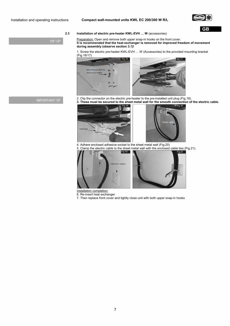
TIP ☞ Preparation: Open and remove both upper snap-in hooks on the front cover. It is recommended that the heat exchanger is removed for improved freedom of movement during assembly (observe section 3.1)!
1. Screw the electric pre-heater KWL-EVH … W (Accessories) to the provided mounting bracket (Fig.16/17)
IMPORTANT ☞ 2. Clip the connector on the electric pre-heater to the pre-installed unit plug (Fig.18).
3. These must be secured to the sheet metal wall for the smooth connection of the electric cable.
4. Adhere enclosed adhesive socket to the sheet metal wall (Fig.20)
5. Clamp the electric cable to the sheet metal wall with the enclosed cable ties (Fig.21).
Installation completion:
6. Re-insert heat exchanger 7. Then replace front cover and tightly close unit with both upper snap-in hooks
Installation and operating instructions Compact wall-mounted units KWL EC 200/300 W R/L
8
GB
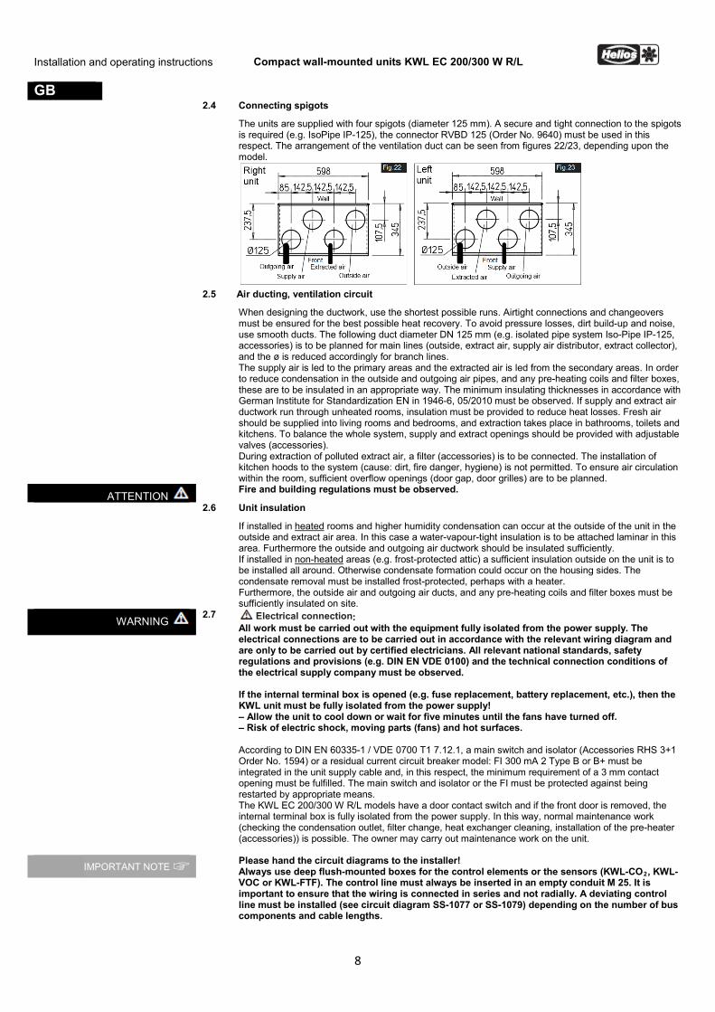
2.4 Connecting spigots
The units are supplied with four spigots (diameter 125 mm). A secure and tight connection to the spigots is required (e.g. IsoPipe IP-125), the connector RVBD 125 (Order No. 9640) must be used in this respect. The arrangement of the ventilation duct can be seen from figures 22/23, depending upon the model.
2.5 Air ducting, ventilation circuit
When designing the ductwork, use the shortest possible runs. Airtight connections and changeovers must be ensured for the best possible heat recovery. To avoid pressure losses, dirt build-up and noise, use smooth ducts. The following duct diameter DN 125 mm (e.g. isolated pipe system Iso-Pipe IP-125, accessories) is to be planned for main lines (outside, extract air, supply air distributor, extract collector), and the ø is reduced accordingly for branch lines. The supply air is led to the primary areas and the extracted air is led from the secondary areas. In order to reduce condensation in the outside and outgoing air pipes, and any pre-heating coils and filter boxes, these are to be insulated in an appropriate way. The minimum insulating thicknesses in accordance with German Institute for Standardization EN in 1946-6, 05/2010 must be observed. If supply and extract air ductwork run through unheated rooms, insulation must be provided to reduce heat losses. Fresh air should be supplied into living rooms and bedrooms, and extraction takes place in bathrooms, toilets and kitchens. To balance the whole system, supply and extract openings should be provided with adjustable valves (accessories). During extraction of polluted extract air, a filter (accessories) is to be connected. The installation of kitchen hoods to the system (cause: dirt, fire danger, hygiene) is not permitted. To ensure air circulation within the room, sufficient overflow openings (door gap, door grilles) are to be planned.
ATTENTION Fire and building regulations must be observed.
2.6 Unit insulation
If installed in heated rooms and higher humidity condensation can occur at the outside of the unit in the outside and extract air area. In this case a water-vapour-tight insulation is to be attached laminar in this area. Furthermore the outside and outgoing air ductwork should be insulated sufficiently. If installed in non-heated areas (e.g. frost-protected attic) a sufficient insulation outside on the unit is to be installed all around. Otherwise condensate formation could occur on the housing sides. The condensate removal must be installed frost-protected, perhaps with a heater. Furthermore, the outside air and outgoing air ducts, and any pre-heating coils and filter boxes must be sufficiently insulated on site.
WARNING 2.7 Electrical connection:
All work must be carried out with the equipment fully isolated from the power supply. The electrical connections are to be carried out in accordance with the relevant wiring diagram and are only to be carried out by certified electricians. All relevant national standards, safety regulations and provisions (e.g. DIN EN VDE 0100) and the technical connection conditions of the electrical supply company must be observed. If the internal terminal box is opened (e.g. fuse replacement, battery replacement, etc.), then the KWL unit must be fully isolated from the power supply! – Allow the unit to cool down or wait for five minutes until the fans have turned off. – Risk of electric shock, moving parts (fans) and hot surfaces.
According to DIN EN 60335-1 / VDE 0700 T1 7.12.1, a main switch and isolator (Accessories RHS 3+1 Order No. 1594) or a residual current circuit breaker model: FI 300 mA 2 Type B or B+ must be integrated in the unit supply cable and, in this respect, the minimum requirement of a 3 mm contact opening must be fulfilled. The main switch and isolator or the FI must be protected against being restarted by appropriate means. The KWL EC 200/300 W R/L models have a door contact switch and if the front door is removed, the internal terminal box is fully isolated from the power supply. In this way, normal maintenance work (checking the condensation outlet, filter change, heat exchanger cleaning, installation of the pre-heater (accessories)) is possible. The owner may carry out maintenance work on the unit.
IMPORTANT NOTE ☞ Please hand the circuit diagrams to the installer! Always use deep flush-mounted boxes for the control elements or the sensors (KWL-CO2, KWL-VOC or KWL-FTF). The control line must always be inserted in an empty conduit M 25. It is important to ensure that the wiring is connected in series and not radially. A deviating control line must be installed (see circuit diagram SS-1077 or SS-1079) depending on the number of bus components and cable lengths.
Installation and operating instructions Compact wall-mounted units KWL EC 200/300 W R/L
9
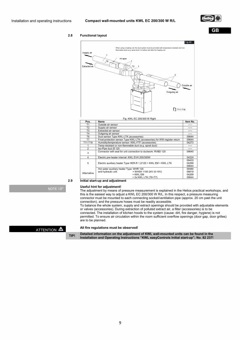
GB 2.8 Functional layout
Fig. KWL EC 200/300 W Right
Pos. Name Item No. T1 Outside air sensor ----- T2 Supply air sensor ----- T3 Extracted air sensor ----- T4 Outgoing air sensor ----- T6 Duct sensor Type KWL-LTK (accessories) 09644 T7 Frost-protection sensor Type KWL-LTK (accessories) for WW-register return 09644
T11-T18 Humidity/temperature sensor: KWL-FTF (accessories) 04273 1 Temp-resistant or non-flammable duct (e.g. spiral duct) ----- 2 Iso-Pipe duct Ø 125 -----
3 Connector with seal for unit connection to ductwork: RVBD 125
09640
4 Electric pre-heater internal: KWL EVH 200/300W 04224
5 Electric auxiliary heater Type HER-R 1.2/125 + KWL EM + KWL LTK 09433 04269 09644
Alternative
Hot water auxiliary heater Type: WHR 125 and hydraulic unit + WHSH 1100 24V (0-10V) + KWL EM + 2x KWL LTK (T6+T7)
09480 08819 04269 09644
2.9 Initial start-up and adjustment
NOTE ☞ Useful hint for adjustment! The adjustment by means of pressure measurement is explained in the Helios practical workshops, and this is the easiest way to adjust a KWL EC 200/300 W R/L. In this respect, a pressure measuring connector must be mounted to each connecting socket/ventilation pipe (approx. 20 cm past the unit connection), and the pressure hoses must be readily accessible. To balance the whole system, supply and extract openings should be provided with adjustable elements or valves (accessories). During extraction of polluted extract air, a filter (accessories) is to be connected. The installation of kitchen hoods to the system (cause: dirt, fire danger, hygiene) is not permitted. To ensure air circulation within the room sufficient overflow openings (door gap, door grilles) are to be planned.
ATTENTION All fire regulations must be observed!
TIP! Detailed information on the adjustment of KWL wall-mounted units can be found in the Installation and Operating Instructions “KWL easyControls Initial start-up”; No. 82 237!
When using a heating coil, the duct system must be provided with temperature-resistant and non-flammable ducts (e.g. spiral duct) 1m before and after the heating coil.
Installation and operating instructions Compact wall-mounted units KWL EC 200/300 W R/L
10
GB
CHAPTER 3 SERVICE AND MAINTENANCE
3.0 Service and maintenance
All work must be carried out with the equipment fully isolated from the power supply!. – Allow the unit to cool down or wait for five minutes until the fans have turned off. – Risk of electric shock, moving parts (fans) and hot surfaces.
WARNING
3.1 Cross counter flow heat exchanger Open and remove both upper snap-in hooks on the front cover (Fig.27). Pull out terminal strip from the heat exchanger (Fig.25). Then carefully remove the heat exchanger from the unit (Fig.26). In order to clean, vacuum the blades with a vacuum cleaner or rinse with warm water.
ATTENTION ☞ Do not use aggressive cleaning products!
IMPORTANT ☞ When installing, insert the heat exchanger into the guide rails and slide in up to the stop. Ensure that the rubber lips are not damaged by mounting! Then re-insert terminal strip.
3.2 Filter change
In order to change the filters, open and remove both upper snap-in hooks on front cover (Fig.27). Then remove the outside air and extract air filter from the metal rails (Fig. 28). A F7 pollen filter is also optionally available.
IMPORTANT ☞ When using F7 filters, pay attention on air flow direction arrows on the filter labels! The air flow direction is shown on the unit label.
– Filter
The KWL compact unit is equipped with outside and extract air filter class G4 as standard (to DIN EN 13779):
Outside air/extract air: 2 units Spare filter Course G4 ELF-KWL 200/300/4/4 Order No. 0021 1 unit Spare filter Fine F7 ELF-KWL 200/300/7 Order No. 0038 2 units Course filter Course G4 ELF-KWL 300/4/4/7 Order No. 0020
NOTE ☞ The filters are to be checked regularly (see controller display, factory setting every 6 months) depending on the degree of pollution, to be cleaned if necessary. By vacuuming once or after a maximum of 1-year operation they must be replaced for hygienic reasons. If the filters should be moist or mouldy, they must be changed immediately!
Installation and operating instructions Compact wall-mounted units KWL EC 200/300 W R/L
11
GB 3.3 Condensation outlet
In connection with maintenance, make sure that the condensation outlet in the bottom reservoir is not clogged (section 2.2). You may check it by pouring a little water into the reservoir.
ATTENTION ☞ Do not let water flow into electrical parts! The condensation outlet must be cleaned once every year!
ATTENTION ☞ Only carry out the work with EMC protection, otherwise EMC damage can occur!
3.4 Access to internal terminal box Open and remove both upper snap-in hooks on the front cover (Fig.27) and remove the heat exchanger. Loosen the screws on the back of the terminal box cover (Fig.29) and remove cover. This guarantees free access to the electronic components (battery, fuse, etc. (Fig.30)). The power unit is completely interchangeable!
3.5 Removal of motor unit using the example – outdoor air fan -
1. In order to remove the motor units, loosen the wing nuts underneath (Fig.31), pull motor unit up and tilt out of the slot (Fig.32).
Installation and operating instructions Compact wall-mounted units KWL EC 200/300 W R/L
12
GB 2. In order to separate the electric cable, completely remove the mounting bracket from the rear wall
(Fig.33). Then press the tab and separate plug connection (Fig.34).
3.6 Removal of electric pre-heater KWL-EVH ... W
1. Open and remove both upper snap-in hooks on the front cover. 2. Remove the electric pre-heater connector plug (accessories) (Fig.35). 3. Then loosen the electric pre-heater fastening screws (Fig.36) and remove the pre-heater.
3.7 Assembly of screwed cable gland for cable anchorage
ATTENTION ☞ 1. Pry open electric cable sleeve and remove from cable (Fig.37). 2. Insert electric cable into the screwed cable gland (Fig.38).
Installation and operating instructions Compact wall-mounted units KWL EC 200/300 W R/L
13
GB 3. Screwed cable gland with tapered edges (Fig.39).
4. Screwed cable gland into opening at an angle (Fig.40).
5. Re-counter and screw two-part screwed cable gland (Fig.41).
6. Ready-assembled cable anchorage for the elec. unit connection cable (Fig.42)
3.8 Other accessories KWL-BE
KWL-BEC KWL-APG KWL-EM KWL-KNX KWL-LTK KWL-CO2 KWL-FTF KWL-VOC KWL-EVH 200/300 W EHR-R 2,4/125 WHR 125 WHSH 1100 24V (0-10V) WHST 300 T38
Order No. 4265 Order No. 4263 Order No. 4270 Order No. 4269 Order No. 4275 Order No. 9644 Order No. 4272 Order No. 4273 Order No. 4274 Order No. 4262 Order No. 9435 Order No. 9481 Order No. 8819 Order No. 8817
Control element Slide switch (flush-mounted) with operation display Control element Comfort (flush-mounted) with 3 m connecting line Control element Comfort (surface-mounted) with 3 m connecting line Extension module EIB Module (for connection to a building control system) Duct sensor for heating coil CO2 sensor to detect the CO2 concentration in the room air Humidity sensor to detect the room air humidity Air quality sensor (to detect the mixed gas concentration) Electric pre-heater 1.0 kW, for plug-in installation Auxiliary heater 2.4 kW, diameter 125 mm Hot water heating coil for standard duct ø 125 mm Temperature control system for hot water heating coil Air temperature control
3.9 Adapter boards with extension module for external heating coil – electrical KWL-EM + EHR-R 1.2/125 + KWL-LTK – hot water KWL-EM + WHSH 1100 24V (0-10V) + KWL-LTK + WHR 125 WHR 125 + WHST 300 T38
Installation and operating instructions Compact wall-mounted units KWL EC 200/300 W R/L
14
GB
CHAPTER 4 DIMENSIONS
4.0 Dimensions
Installation and operating instructions Compact wall-mounted units KWL EC 200/300 W R/L
15
GB
CHAPTER 5 CIRCUIT DIAGRAM WIRING DIAGRAM
5.0 Standard connection diagram SS-1042
Installation and operating instructions Compact wall-mounted units KWL EC 200/300 W R/L
16
GB
5.1 Wiring diagram for KWL EC 200/300 W R/L
Installation and operating instructions Compact wall-mounted units KWL EC 200/300 W R/L
17
GB 5.2 Unit type plate
Technical data for the KWL unit can be found on the unit type plate. Type plate example
Type plate key:
1 2 3 4 5
Manufacturer's address Version: KWL EC = type designation 300 = size W = wall-mounted unit L = left-hand version or R = right-hand version Item number EAN-Code + Item number Indicated rated power Ventilator [kW]
6 7 8 9 10 11 12 13 14 15 16
Rated current Ventilator [A] Voltage range [V] Temperature Rated power pre-heater [kW] Rated current pre-heater [A] Protection class IP Production code / year of manufacture Rated power Total [kW] Rated current Total [A] Installation and operating instructions / No. EAN-Code + serial number
CHAPTER 6
6.0 Frequently asked questions
FREQUENTLY ASKED QUESTIONS
Question Reason Remedial action 1. Condensation outlet not functioning
a.) Siphon leaking > Check for tightness b.) Floating ball in the siphon housing dirty or non-existent
> Clean or insert floating ball (section 2.2)
c.) Siphon clogged > Clean siphon d.) No gradient > Adjust installation
2. Loud operating noise a.) Filter dirty > Clean/replace filter b.) Filter accessories (SEWT, LEWT) dirty
> Clean/replace filter
c.) Commissioning performed incorrectly
> Re-measure volume flows

All illustrations subject to correction! Keep at hand for future reference! Print No. 82 201/11.14 www.heliosventilatoren.de Service and Information D HELIOS Ventilatoren GmbH & Co · Lupfenstraße 8 · 78056 VS-Schwenningen F HELIOS Ventilateurs · Le Carré des Aviateurs · 157 avenue Charles Floquet · 93155 Le Blanc Mesnil Cedex CH HELIOS Ventilatoren AG · Steinackerstraße 36 · 8902 Urdorf / Zürich GB HELIOS Ventilation Systems Ltd. · 5 Crown Gate · Wyncolls Road · Severalls Industrial Park A HELIOS Ventilatoren · Postfach 854 · Siemensstraße 15 · 6023 Innsbruck Colchester · Essex · CO4 9HZ·
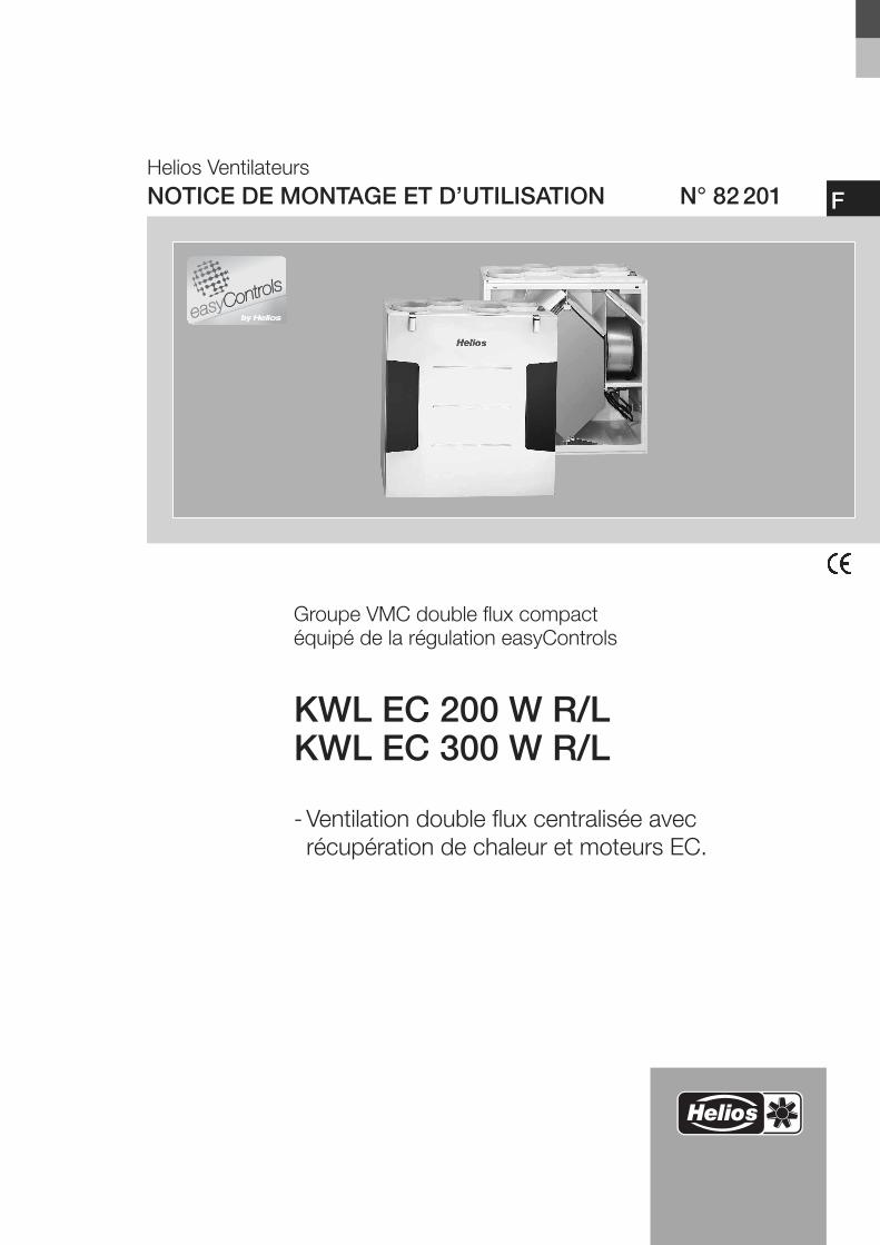
Helios VentilateursNOTICE DE MONTAGE ET D’UTILISATION N° 82201
Groupe VMC double flux compactéquipé de la régulation easyControls
KWL EC 200 W R/LKWL EC 300 W R/L
- Ventilation double flux centralisée avec récupération de chaleur et moteurs EC.
F
NOTICE DE MONTAGE ET D’UTILISATION
SommaireCHAPITRE 1. INFORMATIONS GÉNÉRALES . . . . . . . . . . . . . . . . . . . . . . . . . . . . . . . . . . . . . . . . . . . . . . . . . . . .Page 11.0 Informations importantes . . . . . . . . . . . . . . . . . . . . . . . . . . . . . . . . . . . . . . . . . . . . . . . . . . . . . . . . . . . . . . . .Page 11.1 Précautions et consignes de sécurité . . . . . . . . . . . . . . . . . . . . . . . . . . . . . . . . . . . . . . . . . . . . . . . . . . . . . .Page 11.2 Informations techniques importantes . . . . . . . . . . . . . . . . . . . . . . . . . . . . . . . . . . . . . . . . . . . . . . . . . . . . . . .Page 11.3 Garantie - Réserves du constructeur . . . . . . . . . . . . . . . . . . . . . . . . . . . . . . . . . . . . . . . . . . . . . . . . . . . . . . .Page 11.4 Réglementations – Normes . . . . . . . . . . . . . . . . . . . . . . . . . . . . . . . . . . . . . . . . . . . . . . . . . . . . . . . . . . . . . .Page 11.5 Réception de l’envoi . . . . . . . . . . . . . . . . . . . . . . . . . . . . . . . . . . . . . . . . . . . . . . . . . . . . . . . . . . . . . . . . . . .Page 11.6 Stockage . . . . . . . . . . . . . . . . . . . . . . . . . . . . . . . . . . . . . . . . . . . . . . . . . . . . . . . . . . . . . . . . . . . . . . . . . . . .Page 11.7 Transport . . . . . . . . . . . . . . . . . . . . . . . . . . . . . . . . . . . . . . . . . . . . . . . . . . . . . . . . . . . . . . . . . . . . . . . . . . . .Page 11.8 Domaines d’utilisation . . . . . . . . . . . . . . . . . . . . . . . . . . . . . . . . . . . . . . . . . . . . . . . . . . . . . . . . . . . . . . . . . .Page 21.9 Fonctionnement . . . . . . . . . . . . . . . . . . . . . . . . . . . . . . . . . . . . . . . . . . . . . . . . . . . . . . . . . . . . . . . . . . . . . .Page 21.10 Performances . . . . . . . . . . . . . . . . . . . . . . . . . . . . . . . . . . . . . . . . . . . . . . . . . . . . . . . . . . . . . . . . . . . . . . . .Page 21.11 Foyers atmosphériques . . . . . . . . . . . . . . . . . . . . . . . . . . . . . . . . . . . . . . . . . . . . . . . . . . . . . . . . . . . . . . . . .Page 21.12 Caractéristiques techniques . . . . . . . . . . . . . . . . . . . . . . . . . . . . . . . . . . . . . . . . . . . . . . . . . . . . . . . . . . . . .Page 31.13 Connecteurs RJ avec easyControls . . . . . . . . . . . . . . . . . . . . . . . . . . . . . . . . . . . . . . . . . . . . . . . . . . . . . . . .Page 3
CHAPITRE 2. MONTAGE . . . . . . . . . . . . . . . . . . . . . . . . . . . . . . . . . . . . . . . . . . . . . . . . . . . . . . . . . . . . . . . . . . . .Page 42.0 Montage - Disposition . . . . . . . . . . . . . . . . . . . . . . . . . . . . . . . . . . . . . . . . . . . . . . . . . . . . . . . . . . . . . . . . . .Page 42.1 Montage mural . . . . . . . . . . . . . . . . . . . . . . . . . . . . . . . . . . . . . . . . . . . . . . . . . . . . . . . . . . . . . . . . . . . . . . .Page 42.2 Évacuation des condensats . . . . . . . . . . . . . . . . . . . . . . . . . . . . . . . . . . . . . . . . . . . . . . . . . . . . . . . . . . . . . .Page 52.3 Montage de la batterie électrique KWL-EVH...W (Accessoire) . . . . . . . . . . . . . . . . . . . . . . . . . . . . . . . . . . . .Page 72.4 Raccordement des conduits . . . . . . . . . . . . . . . . . . . . . . . . . . . . . . . . . . . . . . . . . . . . . . . . . . . . . . . . . . . . .Page 82.5 Réseaux et débits d’air . . . . . . . . . . . . . . . . . . . . . . . . . . . . . . . . . . . . . . . . . . . . . . . . . . . . . . . . . . . . . . . . .Page 82.6 Isolation de l’appareil . . . . . . . . . . . . . . . . . . . . . . . . . . . . . . . . . . . . . . . . . . . . . . . . . . . . . . . . . . . . . . . . . . .Page 82.7 Raccordement électrique . . . . . . . . . . . . . . . . . . . . . . . . . . . . . . . . . . . . . . . . . . . . . . . . . . . . . . . . . . . . . . .Page 82.8 Schémas de fonctionnement . . . . . . . . . . . . . . . . . . . . . . . . . . . . . . . . . . . . . . . . . . . . . . . . . . . . . . . . . . . . .Page 92.9 Mise en service et paramétrage . . . . . . . . . . . . . . . . . . . . . . . . . . . . . . . . . . . . . . . . . . . . . . . . . . . . . . . . . . .Page 9
CHAPITRE 3. NETTOYAGE ET ENTRETIEN . . . . . . . . . . . . . . . . . . . . . . . . . . . . . . . . . . . . . . . . . . . . . . . . . . . .Page 103.0 Nettoyage et entretien . . . . . . . . . . . . . . . . . . . . . . . . . . . . . . . . . . . . . . . . . . . . . . . . . . . . . . . . . . . . . . . . .Page 103.1 Échangeur de chaleur à contre-courant . . . . . . . . . . . . . . . . . . . . . . . . . . . . . . . . . . . . . . . . . . . . . . . . . . . .Page 103.2 Remplacement des filtres . . . . . . . . . . . . . . . . . . . . . . . . . . . . . . . . . . . . . . . . . . . . . . . . . . . . . . . . . . . . . .Page 103.3 Évacuation des condensats dans l’appareil . . . . . . . . . . . . . . . . . . . . . . . . . . . . . . . . . . . . . . . . . . . . . . . . .Page 113.4 Accès à la platine électronique . . . . . . . . . . . . . . . . . . . . . . . . . . . . . . . . . . . . . . . . . . . . . . . . . . . . . . . . . .Page 113.5 Démontage du ventilateur d’extraction . . . . . . . . . . . . . . . . . . . . . . . . . . . . . . . . . . . . . . . . . . . . . . . . . . . .Page 113.6 Démontage de la batterie électrique KWL-EVH ... W . . . . . . . . . . . . . . . . . . . . . . . . . . . . . . . . . . . . . . . . . .Page 123.7 Montage du presse-étoupe anti-arrachement . . . . . . . . . . . . . . . . . . . . . . . . . . . . . . . . . . . . . . . . . . . . . . .Page 123.8 Accessoires divers . . . . . . . . . . . . . . . . . . . . . . . . . . . . . . . . . . . . . . . . . . . . . . . . . . . . . . . . . . . . . . . . . . . .Page 133.9 Connexions possibles avec modules d’extension pour batterie externe . . . . . . . . . . . . . . . . . . . . . . . . . . . .Page 13
CHAPITRE 4. DIMENSIONS . . . . . . . . . . . . . . . . . . . . . . . . . . . . . . . . . . . . . . . . . . . . . . . . . . . . . . . . . . . . . . . . .Page 144.0 Dimensions . . . . . . . . . . . . . . . . . . . . . . . . . . . . . . . . . . . . . . . . . . . . . . . . . . . . . . . . . . . . . . . . . . . . . . . . .Page 14
CHAPITRE 5. SCHÉMAS DE BRANCHEMENT ET DE RACCORDEMENT . . . . . . . . . . . . . . . . . . . . . . . . . . . . .Page 155.0 Schéma de branchement standard SS-1042 . . . . . . . . . . . . . . . . . . . . . . . . . . . . . . . . . . . . . . . . . . . . . . . .Page 155.1 Schémas de raccordement KWL EC 200/300 W R/L . . . . . . . . . . . . . . . . . . . . . . . . . . . . . . . . . . . . . . . . .Page 165.2 Plaque signalétique . . . . . . . . . . . . . . . . . . . . . . . . . . . . . . . . . . . . . . . . . . . . . . . . . . . . . . . . . . . . . . . . . . .Page 17
CHAPITRE 6. FAQ6.0 FAQ . . . . . . . . . . . . . . . . . . . . . . . . . . . . . . . . . . . . . . . . . . . . . . . . . . . . . . . . . . . . . . . . . . . . . . . . . . . . . . .Page 17
FRANÇAIS
Tri correct de ce produit (appareillage électronique)Le sigle présent sur ce produit et sur la notice de montage et d’utilisation indique, qu’en fin de vie, celui–ci ne doit pas être jeté avec les ordures ménagères classiques.Ne mettez pas cet appareil avec les autres déchets pour ne pas nuire à l’environnement, ni à la santé publique suite à un recyclage d’ordures non contrôlées. Recyclercet appareil pour encourager la récupération efficace des ressources. Le particulier devrait contacter le revendeur, chez lequel ce produit a été acheté, ou les autoritéscompétentes, pour s’informer de la meilleure façon de recycler l’appareil.
Les utilisateurs professionnels devraient s’adresser à leurs fournisseurs et consulter les modalités du contrat de vente.Ce produit ne doit pas être trié avec les autres déchets industriels.
1.0 Informations importantesIl est important de bien lire et suivre l’ensemble des consignes suivantes pour le bon fonctionnement de l’appareil etpour la sécurité des utilisateurs. Veiller à bien respecter les normes nationales, règlements de sécurité et instructions.
Le bureau d'études réalise le dossier technique de l'installation de ventilation double flux. Des informations complémentairespeuvent être demandées à l’usine. Conserver la notice de montage et d’utilisation comme référence à proximité del’appareil. Une fois le montage terminé, ce document doit être remis en mains propres à l’utilisateur (locataire ou propriétaire).
Sommaire de la notice de montage et d’installation: Chapitres 1–3 Informations générales, consignes d’utilisation, installation et mise en service de l’appareil (régulation).
> Destinés à l’installateur.Chapitres 4–5 Accessoires + Nettoyage et entretien.
> Destinés à l’installateur et à l’utilisateur final.Le manuel d’utilisation « easyControls » (N° 82 200) est livré avec la centrale et contient toutes les informations d’utilisation et de commande. Le manuel d’utilisation de la machine est destiné à l’installateur et à l’utilisateur final.
1.1 Précautions et consignes de sécurité Le symbole ci-contre indique une consigne de sécurité. Toutes les consignes de sécurité, ainsi que les symboles,doivent impérativement être respectés, afin d’éviter tout danger.
1.2 Informations techniques importantesLes centrales KWL EC 200/300 W R/L sont équipées d’un contacteur de porte. Si le panneau frontal est retiré, l’alimentation du secteur se coupera au niveau de la carte électronique située dans l’appareil. Il sera possible d’effectuerl’entretien de l’appareil avec par ex. la vérification de l’évacuation des condensats, le remplacement des filtres, lenettoyage de l’échangeur, le montage de la batterie de préchauffage (si l’accessoire a été choisi), etc.L’ouverture de la carte électronique ne peut se faire que par une personne ayant une habilitation électricité!Toutes les démarches à suivre sont indiquées dans le chapitre 2.
1.3 Demande de garantie - Réserves du constructeur Toute demande de remplacement ou de réparation à titre gratuit sera déclinée en cas de non-respect des indicationssuivantes:– Mise en service selon la notice de montage et d’utilisation de la centrale.– Mise en service selon le manuel d’utilisation « easyControls ».– L’utilisation d’accessoires, non fournis, non conseillés ou non proposés par Helios, est interdite.
Si ces consignes ne sont pas respectées, la garantie s’annule. Idem pour les réserves constructeur.
1.4 Réglementation – NormesCet appareil est conforme aux directives CE en vigueur le jour de sa fabrication sous réserve d’une utilisation appropriée.
1.5 Réception de la marchandiseLa livraison comprend la centrale de type: KWL EC 200 W R/L
ou la centrale de type: KWL EC 300 W R/LDès réception, vérifier l’état et la conformité du matériel commandé. En cas d’avaries, des réserves doivent être portéessur le bordereau du transporteur. Elles doivent être précises, significatives, complètes et confirmées par lettrerecommandée au transporteur. Attention, le non-respect de la procédure peut entraîner le rejet de la réclamation.
1.6 StockagePour un stockage de longue durée et pour éviter toute détérioration préjudiciable, se conformer à ces instructions:protéger la centrale grâce à un emballage sec, étanche à l’air et à la poussière (sac en matière synthétique contenantdes sachets déshydrateurs et un indicateur d’humidité) et stocker le matériel dans un endroit abrité de l’eau, exempt devariation de températures et de vibrations. Les dommages dûs à de mauvaises conditions de transport ou de stockage,à une utilisation anormale sont sujets à vérification et contrôle et entraînent la suppression de la garantie Helios.
1.7 TransportL'appareil est emballé en usine et protégé contre les dégâts de transport courants. Transporter l'appareil avec soin.Il est préférable de laisser l'appareil dans son emballage d'origine jusqu'au montage sur site pour éviter chocs et poussières.
1
Groupe double flux compact KWL EC 200/300 W R/LNotice de montage et d’utilisation
CHAPITRE 1INFORMATIONSGÉNÉRALES
FFélicitationsVous venez d’acquérir un produit Helios Ventilateurs. Vous avez donc opté pour un produit de qualité dont vous profiterez pendant de nombreuses années.Toutes les centrales KWL EC 200/300 W ...R/L ont été testées dans leur intégralité par notre service fabrication. Ces tests ne s’arrêtent pas aux fonctionnalitésvisibles de l’appareil (comme par ex. le bon fonctionnement des ventilateurs), mais concernent également les fonctions qui ne peuvent être testées par nosclients. Nous vérifions par ex. l’étanchéité interne et externe du produit ainsi que sa protection électrique. À travers des idées innovantes en matière derégulation et de contrôle, nous réduisons les coûts de fonctionnement. Cela passe par ex. par une gestion intelligente de la protection antigel de l’échangeuroptimisée par calcul et surveillance du rendement de celui-ci.Si vous rencontrez un problème quelconque avec notre produit, rapprochez-vous de votre installateur ou du service après-vente.
�
AVERTISSEMENT �
IMPORTANT �
ASTUCE!ASTUCE!
1.8 Domaines d’utilisationLes groupes double flux compacts KWL EC 200/300 W .. R/L avec récupération de chaleur sont prévus pour laventilation centralisée de logements individuels, maisons et appartements. Ils sont équipés de série de la régulationinnovante easyControls, pour une connexion au réseau Internet très simple, via navigateur Web, et, d’un échangeur àcontre-courant synthétique haute efficacité, avec une récupération d’énergie d’environ (voir tableau ci-dessous):
L’appareil doit être installé et utilisé dans des locaux hors gel (5 °C min.). En cas d’utilisation dans des conditionsdifficiles (forte hygrométrie, arrêts de longue durée, fortes poussières, incidences techniques et électromagnétiquesparticulières), il convient de demander conseil et d’obtenir une autorisation du constructeur. Toute autre utilisation n’est pas autorisée!
1.9 FonctionnementLa centrale double flux KWL possède un échangeur statique à contre-courant dans lequel l'air extérieur froid et l’airextrait chaud se croisent sans contact direct entre eux. Grâce à ce principe, la plus grande partie des calories de l’airextrait sont transmises à l’air extérieur. L’air extérieur est amené aux locaux d’habitation par un réseau de gaines et desbouches de soufflage. L’air repris provient des WC, salle de bain et cuisine. Par un réseau de gaines, il est amené àl’appareil puis rejeté vers l’extérieur par un réseau d’extraction.L'efficacité thermique dépend de plusieurs facteurs qui sont par ex. l'humidité de l'air et la différence de températureentre l'air extérieur et l'air repris. Le débit d'air peut être réglé via le navigateur Web embarqué (livré d'usine). La centralepeut également être contrôlée avec une commande à distance (accessoire). Deux commandes à distance sontdisponibles au choix: KWL-BE et KWL-BEC.Une régulation automatique peut être réalisée avec la sonde COV, sonde de qualité d’air (type KWL-VOC, option), lasonde de dioxyde de carbone (type KWL-CO2, option), la sonde d’hygrométrie (type KWL-FTF) ou encore avecl’horloge hebdomadaire (types WSUP et WSUP-S, option).
La batterie de préchauffage électrique KWL-EVH (accessoire, Réf. N° 4224) réchauffe l’air extérieur en cas detempérature extérieure très basse, empêchant ainsi le givrage de l’échangeur et permettant un rendement optimal,même en hiver. Il est possible d’augmenter la température de soufflage grâce à une batterie externe, électrique ou àeau chaude, pilotée par la régulation de la machine (accessoire EHR-R... ou WHR). Une autre possibilité consiste àrafraîchir l’air extérieur en faisant passer l’air intérieur plus frais sur l’échangeur.Pour les saisons chaudes, le bypass été est la solution optimale pour faire pénétrer à l’intérieur du bâtiment de l’airfrais. Grâce au filtre intégré, l’air sera filtré de façon optimale, permettant de garantir à la fois une meilleure hygiène ainsiqu’une durée de vie plus longue de l’appareil. Deux filtres G4 pour l’air extérieur et pour l’air repris sont fournis de série(filtre F7 anti-pollen, en option).
1.10 PerformancesUn montage selon les règles de l’art ainsi qu’une aspiration et un soufflage sans entrave sont la garantie d’un bonfonctionnement. Le réseau doit être parfaitement dimensionné et installé afin d’atteindre les performances souhaitées(débit, acoustique, puissance absorbée, pression max.). Un changement régulier de filtre est également nécessairepour maintenir une performance optimale du système. Une installation dans les règles de l’art de tous les composants(centrale et périphérie) est indispensable.
Helios propose régulièrement des ateliers pratiques complets sur ce thème. Renseignez-vous auprès de votrecorrespondant Helios.
Des réalisations non-conformes et/ou des conditions d’installation et de fonctionnement défavorables peuventconduire à une réduction des performances ou à une augmentation du niveau sonore. Les données acoustiques sontindiquées en puissance sonore LWA pondérée en dB(A) (conformément à la norme DIN 45 635 T.1). Les données enpression sonore pondérée LPA dépendent des caractéristiques spécifiques de la pièce. Celles-ci influencent de façondécisive le niveau sonore généré.
1.11 Foyers atmosphériquesL’utilisation simultanée d’une ventilation contrôlée (KWL...) et d’un appareil de chauffage à foyer atmosphérique(chaudière à gaz, poêle à bois, cheminée à foyer ouvert ou fermé...) doit se faire dans le respect des réglementations envigueur. Dans les bâtiments construits selon les nouvelles réglementations thermiques, le fonctionnement d'un appareilde chauffage à foyer atmosphérique n'est permis que si l’apport d’air pour la combustion est assuré par un systèmeindépendant et couplé à cet appareil; le fonctionnement simultané d'une KWL et d'un foyer atmosphérique n'estautorisé qu'à cette condition.
– Recommandations particulièresLes centrales double flux avec récupération de chaleur KWL ne peuvent être installées et fonctionner simultanémentdans des locaux avec foyers ouverts que si l’évacuation des gaz brûlés est contrôlée par un dispositif de sécurité (fourniture client) qui coupe la ventilation pendant le fonctionnement du chauffage. La centrale KWL restera coupée tantque le foyer atmosphérique restera actif. Par ailleurs, il faut s’assurer que lors du fonctionnement de la ventilation, ladépression dans la pièce ne dépasse pas 4 Pa.
2
Groupe double flux compact KWL EC 200/300 W R/LNotice de montage et d’utilisation
F
Type Débit d’air nominal [m³/h] 120 168 251
KWL EC 200 W R/L Efficacité thermique 90 % 85 % 84 %
KWL EC 300 W R/L Efficacité thermique 90 % 85 % 84 %
IMPORTANT �
IMPORTANT �
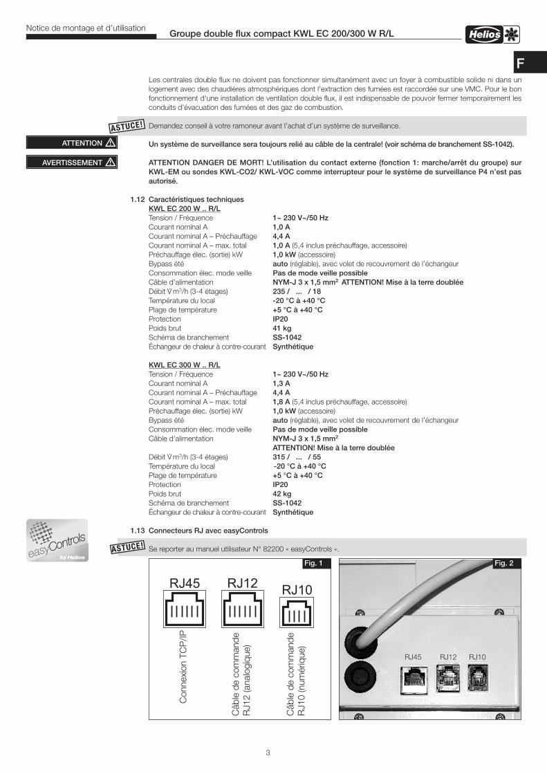
ASTUCE!ASTUCE!
RJ12
Steu
erle
itun
g RJ
10 (
digi
tal
)
RJ45
Steu
erle
itun
g RJ
12 (
Anal
og )
RJ10
TCP/
IP V
erbi
ndun
g
Fig. 1 Fig. 2
RJ45 RJ12 RJ10
ASTUCE!ASTUCE!
Les centrales double flux ne doivent pas fonctionner simultanément avec un foyer à combustible solide ni dans un logement avec des chaudières atmosphériques dont l’extraction des fumées est raccordée sur une VMC. Pour le bonfonctionnement d'une installation de ventilation double flux, il est indispensable de pouvoir fermer temporairement lesconduits d’évacuation des fumées et des gaz de combustion.
Demandez conseil à votre ramoneur avant l’achat d’un système de surveillance.
Un système de surveillance sera toujours relié au câble de la centrale! (voir schéma de branchement SS-1042).
ATTENTION DANGER DE MORT! L’utilisation du contact externe (fonction 1: marche/arrêt du groupe) surKWL-EM ou sondes KWL-CO2/ KWL-VOC comme interrupteur pour le système de surveillance P4 n’est pasautorisé.
1.12 Caractéristiques techniques KWL EC 200 W .. R/L Tension / Fréquence 1~ 230 V~/50 Hz Courant nominal A 1,0 A Courant nominal A – Préchauffage 4,4 A Courant nominal A – max. total 1,0 A (5,4 inclus préchauffage, accessoire)
Préchauffage élec. (sortie) kW 1,0 kW (accessoire)Bypass été auto (réglable), avec volet de recouvrement de l’échangeurConsommation élec. mode veille Pas de mode veille possibleCâble d’alimentation NYM-J 3 x 1,5 mm2 ATTENTION! Mise à la terre doubléeDébit V· m3/h (3-4 étages) 235 / ... / 18
Température du local -20 °C à +40 °CPlage de température +5 °C à +40 °CProtection IP20Poids brut 41 kg
Schéma de branchement SS-1042 Échangeur de chaleur à contre-courant Synthétique KWL EC 300 W .. R/L Tension / Fréquence 1~ 230 V~/50 Hz Courant nominal A 1,3 A Courant nominal A – Préchauffage 4,4 A Courant nominal A – max. total 1,8 A (5,4 inclus préchauffage, accessoire)
Préchauffage élec. (sortie) kW 1,0 kW (accessoire)Bypass été auto (réglable), avec volet de recouvrement de l’échangeurConsommation élec. mode veille Pas de mode veille possibleCâble d’alimentation NYM-J 3 x 1,5 mm2
ATTENTION! Mise à la terre doublée Débit V· m3/h (3-4 étages) 315 / ... / 55
Température du local -20 °C à +40 °CPlage de température +5 °C à +40 °CProtection IP20Poids brut 42 kg
Schéma de branchement SS-1042 Échangeur de chaleur à contre-courant Synthétique
1.13 Connecteurs RJ avec easyControls
Se reporter au manuel utilisateur N° 82200 « easyControls ».
ATTENTION �
AVERTISSEMENT �
3
Groupe double flux compact KWL EC 200/300 W R/LNotice de montage et d’utilisation
F
Connexion TCP/IP
Câble de commande
RJ10 (numérique)
Câble de commande
RJ12 (analogique)
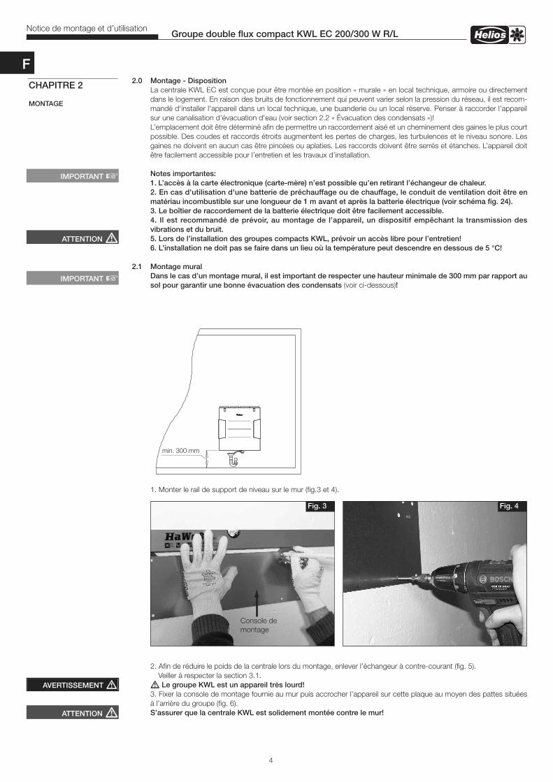
2.0 Montage - DispositionLa centrale KWL EC est conçue pour être montée en position « murale » en local technique, armoire ou directementdans le logement. En raison des bruits de fonctionnement qui peuvent varier selon la pression du réseau, il est recom-mandé d'installer l'appareil dans un local technique, une buanderie ou un local réserve. Penser à raccorder l'appareilsur une canalisation d'évacuation d'eau (voir section 2.2 « Évacuation des condensats »)!L’emplacement doit être déterminé afin de permettre un raccordement aisé et un cheminement des gaines le plus courtpossible. Des coudes et raccords étroits augmentent les pertes de charges, les turbulences et le niveau sonore. Lesgaines ne doivent en aucun cas être pincées ou aplaties. Les raccords doivent être serrés et étanches. L’appareil doitêtre facilement accessible pour l’entretien et les travaux d’installation.
Notes importantes:1. L’accès à la carte électronique (carte-mère) n’est possible qu’en retirant l’échangeur de chaleur.2. En cas d'utilisation d'une batterie de préchauffage ou de chauffage, le conduit de ventilation doit être enmatériau incombustible sur une longueur de 1 m avant et après la batterie électrique (voir schéma fig. 24).3. Le boîtier de raccordement de la batterie électrique doit être facilement accessible.4. Il est recommandé de prévoir, au montage de l’appareil, un dispositif empêchant la transmission des vibrations et du bruit.5. Lors de l’installation des groupes compacts KWL, prévoir un accès libre pour l’entretien!6. L’installation ne doit pas se faire dans un lieu où la température peut descendre en dessous de 5 °C!
2.1 Montage muralDans le cas d’un montage mural, il est important de respecter une hauteur minimale de 300 mm par rapport ausol pour garantir une bonne évacuation des condensats (voir ci-dessous)!
1. Monter le rail de support de niveau sur le mur (fig.3 et 4).
2. Afin de réduire le poids de la centrale lors du montage, enlever l’échangeur à contre-courant (fig. 5). Veiller à respecter la section 3.1.� Le groupe KWL est un appareil très lourd!3. Fixer la console de montage fournie au mur puis accrocher l’appareil sur cette plaque au moyen des pattes situéesà l’arrière du groupe (fig. 6). S’assurer que la centrale KWL est solidement montée contre le mur!
4
Groupe double flux compact KWL EC 200/300 W R/LNotice de montage et d’utilisation
CHAPITRE 2
MONTAGE
ATTENTION �
IMPORTANT �
IMPORTANT �
ATTENTION �
AVERTISSEMENT �
mind. 300 mm
Fig. 3 Fig. 4
Console demontage
F
min. 300 mm
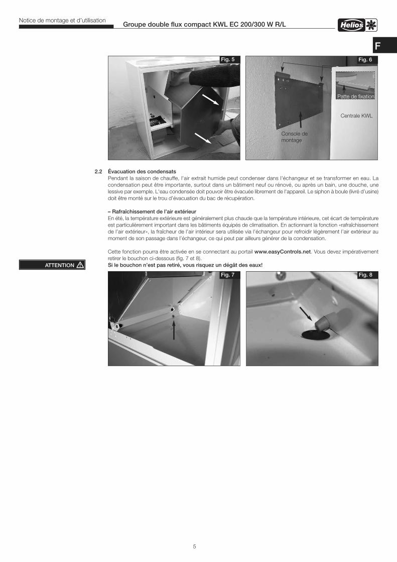
2.2 Évacuation des condensats Pendant la saison de chauffe, l'air extrait humide peut condenser dans l'échangeur et se transformer en eau. Lacondensation peut être importante, surtout dans un bâtiment neuf ou rénové, ou après un bain, une douche, unelessive par exemple. L'eau condensée doit pouvoir être évacuée librement de l'appareil. Le siphon à boule (livré d’usine)doit être monté sur le trou d’évacuation du bac de récupération.
– Rafraîchissement de l’air extérieurEn été, la température extérieure est généralement plus chaude que la température intérieure, cet écart de températureest particulièrement important dans les bâtiments équipés de climatisation. En actionnant la fonction «rafraîchissementde l’air extérieur», la fraîcheur de l’air intérieur sera utilisée via l’échangeur pour refroidir légèrement l’air extérieur aumoment de son passage dans l’échangeur, ce qui peut par ailleurs générer de la condensation.
Cette fonction pourra être activée en se connectant au portail www.easyControls.net. Vous devez impérativementretirer le bouchon ci-dessous (fig. 7 et 8).Si le bouchon n’est pas retiré, vous risquez un dégât des eaux!
5
Groupe double flux compact KWL EC 200/300 W R/LNotice de montage et d’utilisation
ATTENTION �
Fig. 5 Fig. 6
Centrale KWL
Console demontage
Fig. 7 Fig. 8
Patte de fixation
F
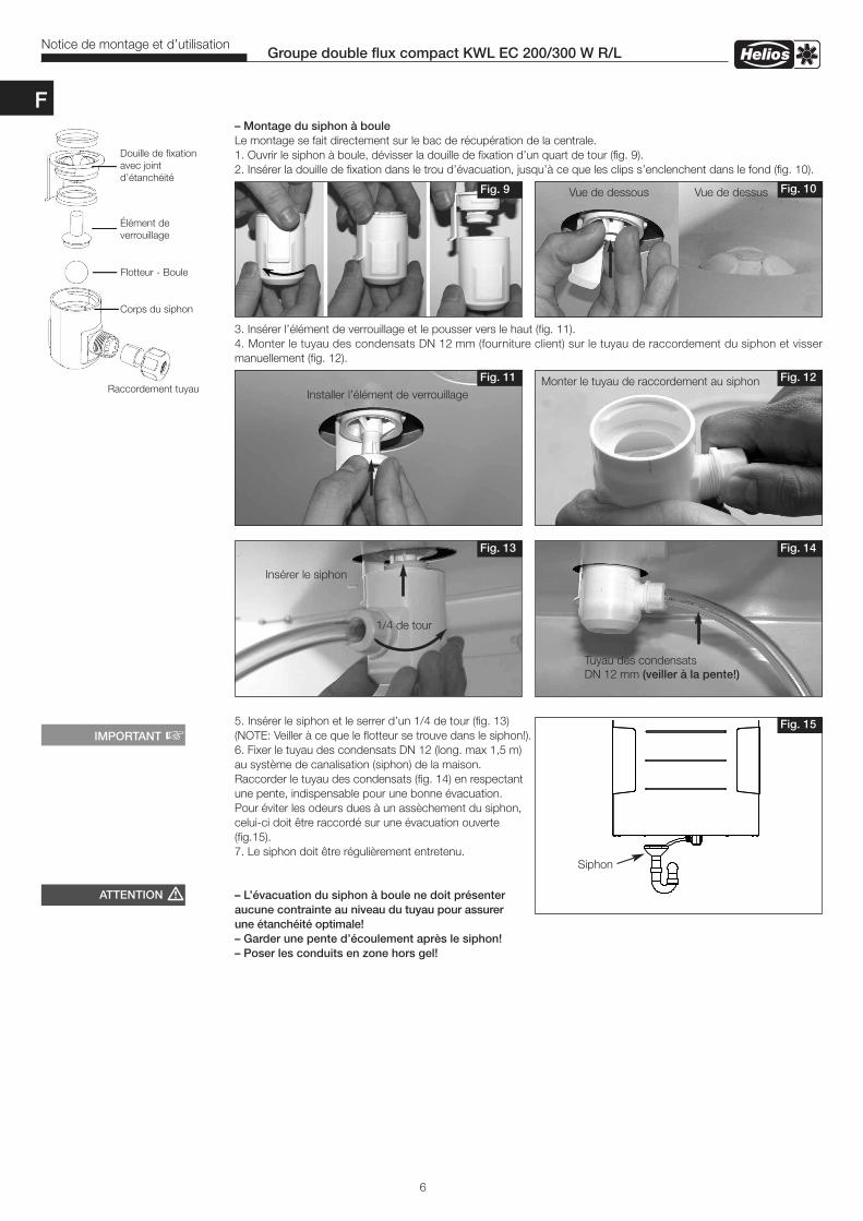
Fig. 10Vue de dessous Vue de dessus
– Montage du siphon à bouleLe montage se fait directement sur le bac de récupération de la centrale.1. Ouvrir le siphon à boule, dévisser la douille de fixation d’un quart de tour (fig. 9).2. Insérer la douille de fixation dans le trou d’évacuation, jusqu’à ce que les clips s’enclenchent dans le fond (fig. 10).
3. Insérer l’élément de verrouillage et le pousser vers le haut (fig. 11).4. Monter le tuyau des condensats DN 12 mm (fourniture client) sur le tuyau de raccordement du siphon et vissermanuellement (fig. 12).
5. Insérer le siphon et le serrer d’un 1/4 de tour (fig. 13) (NOTE: Veiller à ce que le flotteur se trouve dans le siphon!).6. Fixer le tuyau des condensats DN 12 (long. max 1,5 m) au système de canalisation (siphon) de la maison. Raccorder le tuyau des condensats (fig. 14) en respectantune pente, indispensable pour une bonne évacuation. Pour éviter les odeurs dues à un assèchement du siphon,celui-ci doit être raccordé sur une évacuation ouverte (fig.15). 7. Le siphon doit être régulièrement entretenu.
– L’évacuation du siphon à boule ne doit présenteraucune contrainte au niveau du tuyau pour assurerune étanchéité optimale!– Garder une pente d’écoulement après le siphon!– Poser les conduits en zone hors gel!
6
Groupe double flux compact KWL EC 200/300 W R/LNotice de montage et d’utilisation
Fig. 14Fig. 13
Tuyau des condensatsDN 12 mm (veiller à la pente!)
1/4 de tour
Insérer le siphon
Fig. 15
Siphon
ATTENTION �
IMPORTANT �
Fig. 12Fig. 11
Installer l’élément de verrouillageMonter le tuyau de raccordement au siphon
Fig. 9
F
Douille de fixationavec jointd’étanchéité
Élément deverrouillage
Flotteur - Boule
Corps du siphon
Raccordement tuyau
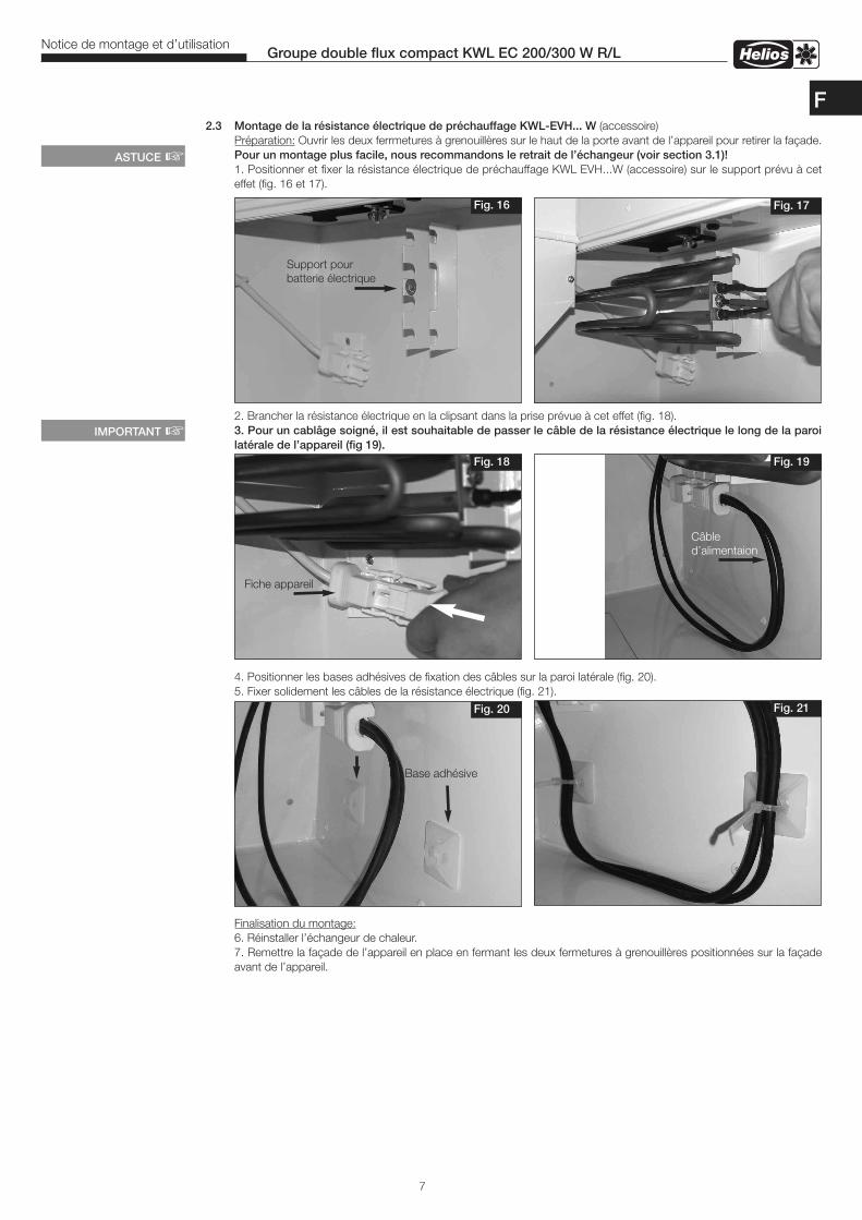
7
Groupe double flux compact KWL EC 200/300 W R/LNotice de montage et d’utilisation
2.3 Montage de la résistance électrique de préchauffage KWL-EVH... W (accessoire)Préparation: Ouvrir les deux ferrmetures à grenouillères sur le haut de la porte avant de l’appareil pour retirer la façade.Pour un montage plus facile, nous recommandons le retrait de l’échangeur (voir section 3.1)!1. Positionner et fixer la résistance électrique de préchauffage KWL EVH...W (accessoire) sur le support prévu à ceteffet (fig. 16 et 17).
2. Brancher la résistance électrique en la clipsant dans la prise prévue à cet effet (fig. 18).3. Pour un cablâge soigné, il est souhaitable de passer le câble de la résistance électrique le long de la paroilatérale de l’appareil (fig 19).
4. Positionner les bases adhésives de fixation des câbles sur la paroi latérale (fig. 20).5. Fixer solidement les câbles de la résistance électrique (fig. 21).
Finalisation du montage:6. Réinstaller l’échangeur de chaleur.7. Remettre la façade de l’appareil en place en fermant les deux fermetures à grenouillères positionnées sur la façadeavant de l’appareil.
Fig. 18
Fig. 17Fig. 16
ASTUCE �
Support pourbatterie électrique
Fig. 19
Fig. 20 Fig. 21
Base adhésive
Fiche appareil
IMPORTANT �
F
Câble d’alimentaion
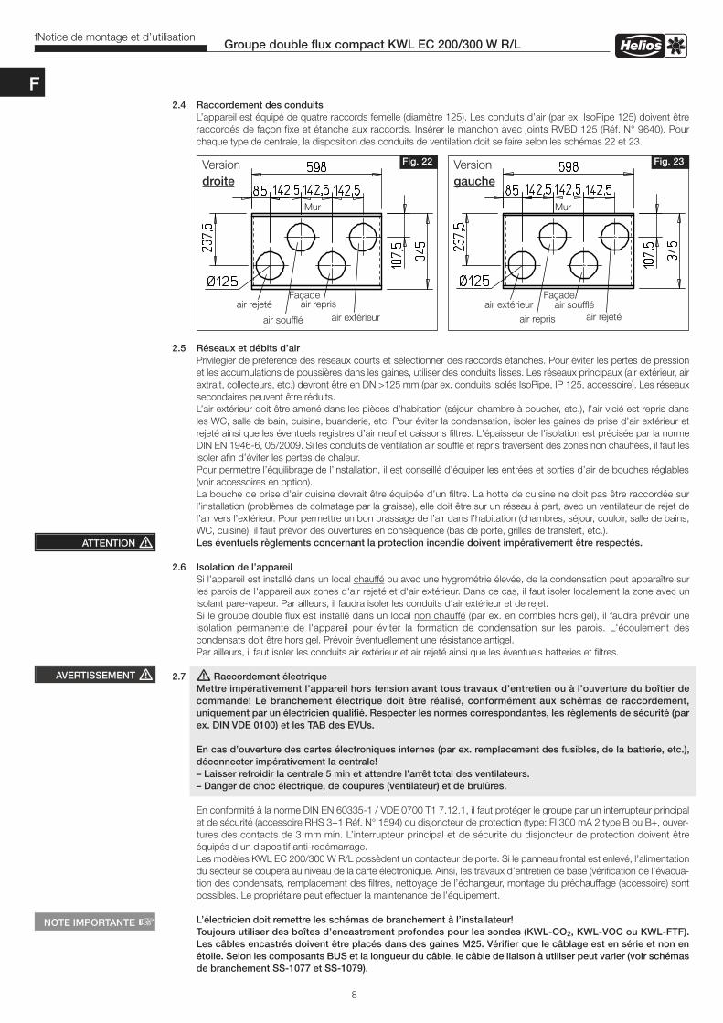
2.4 Raccordement des conduitsL’appareil est équipé de quatre raccords femelle (diamètre 125). Les conduits d’air (par ex. IsoPipe 125) doivent êtreraccordés de façon fixe et étanche aux raccords. Insérer le manchon avec joints RVBD 125 (Réf. N° 9640). Pourchaque type de centrale, la disposition des conduits de ventilation doit se faire selon les schémas 22 et 23.
2.5 Réseaux et débits d’airPrivilégier de préférence des réseaux courts et sélectionner des raccords étanches. Pour éviter les pertes de pressionet les accumulations de poussières dans les gaines, utiliser des conduits lisses. Les réseaux principaux (air extérieur, airextrait, collecteurs, etc.) devront être en DN >125 mm (par ex. conduits isolés IsoPipe, IP 125, accessoire). Les réseauxsecondaires peuvent être réduits.L’air extérieur doit être amené dans les pièces d’habitation (séjour, chambre à coucher, etc.), l’air vicié est repris dansles WC, salle de bain, cuisine, buanderie, etc. Pour éviter la condensation, isoler les gaines de prise d’air extérieur etrejeté ainsi que les éventuels registres d’air neuf et caissons filtres. L'épaisseur de l'isolation est précisée par la normeDIN EN 1946-6, 05/2009. Si les conduits de ventilation air soufflé et repris traversent des zones non chauffées, il faut lesisoler afin d’éviter les pertes de chaleur.Pour permettre l’équilibrage de l’installation, il est conseillé d’équiper les entrées et sorties d’air de bouches réglables(voir accessoires en option).La bouche de prise d’air cuisine devrait être équipée d’un filtre. La hotte de cuisine ne doit pas être raccordée surl’installation (problèmes de colmatage par la graisse), elle doit être sur un réseau à part, avec un ventilateur de rejet del’air vers l’extérieur. Pour permettre un bon brassage de l’air dans l’habitation (chambres, séjour, couloir, salle de bains,WC, cuisine), il faut prévoir des ouvertures en conséquence (bas de porte, grilles de transfert, etc.).Les éventuels règlements concernant la protection incendie doivent impérativement être respectés.
2.6 Isolation de l’appareilSi l’appareil est installé dans un local chauffé ou avec une hygrométrie élevée, de la condensation peut apparaître surles parois de l'appareil aux zones d'air rejeté et d'air extérieur. Dans ce cas, il faut isoler localement la zone avec unisolant pare-vapeur. Par ailleurs, il faudra isoler les conduits d'air extérieur et de rejet.Si le groupe double flux est installé dans un local non chauffé (par ex. en combles hors gel), il faudra prévoir uneisolation permanente de l'appareil pour éviter la formation de condensation sur les parois. L'écoulement descondensats doit être hors gel. Prévoir éventuellement une résistance antigel.Par ailleurs, il faut isoler les conduits air extérieur et air rejeté ainsi que les éventuels batteries et filtres.
2.7 � Raccordement électriqueMettre impérativement l’appareil hors tension avant tous travaux d’entretien ou à l’ouverture du boîtier decommande! Le branchement électrique doit être réalisé, conformément aux schémas de raccordement,uniquement par un électricien qualifié. Respecter les normes correspondantes, les règlements de sécurité (parex. DIN VDE 0100) et les TAB des EVUs.
En cas d’ouverture des cartes électroniques internes (par ex. remplacement des fusibles, de la batterie, etc.),déconnecter impérativement la centrale!– Laisser refroidir la centrale 5 min et attendre l’arrêt total des ventilateurs.– Danger de choc électrique, de coupures (ventilateur) et de brulûres.
En conformité à la norme DIN EN 60335-1 / VDE 0700 T1 7.12.1, il faut protéger le groupe par un interrupteur principalet de sécurité (accessoire RHS 3+1 Réf. N° 1594) ou disjoncteur de protection (type: FI 300 mA 2 type B ou B+, ouver-tures des contacts de 3 mm min. L’interrupteur principal et de sécurité du disjoncteur de protection doivent êtreéquipés d’un dispositif anti-redémarrage.Les modèles KWL EC 200/300 W R/L possèdent un contacteur de porte. Si le panneau frontal est enlevé, l’alimentationdu secteur se coupera au niveau de la carte électronique. Ainsi, les travaux d’entretien de base (vérification de l’évacua-tion des condensats, remplacement des filtres, nettoyage de l’échangeur, montage du préchauffage (accessoire) sontpossibles. Le propriétaire peut effectuer la maintenance de l’équipement.
L’électricien doit remettre les schémas de branchement à l’installateur! Toujours utiliser des boîtes d’encastrement profondes pour les sondes (KWL-CO2, KWL-VOC ou KWL-FTF).Les câbles encastrés doivent être placés dans des gaines M25. Vérifier que le câblage est en série et non enétoile. Selon les composants BUS et la longueur du câble, le câble de liaison à utiliser peut varier (voir schémasde branchement SS-1077 et SS-1079).
8
Groupe double flux compact KWL EC 200/300 W R/LfNotice de montage et d’utilisation
ATTENTION �
Versiondroite
Versiongauche
Fig. 22 Fig. 23
Mur Mur
Façade
AVERTISSEMENT �
Façade
NOTE IMPORTANTE �
F
air rejetéair rejetéair soufflé
air souffléair extérieur
air extérieurair repris
air repris
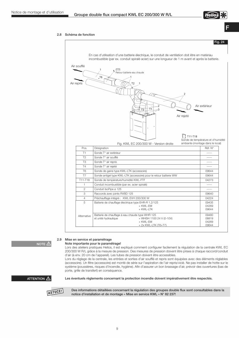
ASTUCE!ASTUCE!
2.8 Schéma de fonction
2.9 Mise en service et paramétrage Note importante pour le paramétrage!
Lors des ateliers pratiques Helios, il est expliqué comment configurer facilement la régulation de la centrale KWL EC200/300 W R/L grâce à la mesure de pression. Des mesures de pression doivent être prises à chaque raccord/conduitd’air (à env. 20 cm de l’appareil). Les tubes de pression doivent être accessibles.Lors du réglage de la centrale, les entrées et sorties d’air soufflé et repris sont équipées avec des éléments réglables(accessoire). Un filtre (accessoire) est monté de série sur l’aspiration de l’air repris/vicié. Ne pas installer de hotte sur lesystème (poussières, risques d’incendie, hygiène). Afin d’assurer un bon brassage d’air, prévoir des ouvertures (bas deporte, grille de transfert) en conséquence.
Les éventuels règlements concernant la protection incendie doivent impérativement être respectés.
Des informations détaillées concernant la régulation des groupes double flux sont consultables dans la notice d’installation et de montage « Mise en service KWL » N° 82 237!
9
Groupe double flux compact KWL EC 200/300 W R/LNotice de montage et d’utilisation
Fig. 24
ATTENTION �
NOTE �
F
En cas d’utilisation d’une batterie électrique, le conduit de ventilation doit être en matériauincombustible (par ex. conduit spiralé acier) sur une longueur de 1 m avant et après la batterie.
Air repris
Air soufflé
Air rejeté
Air extérieur
Fig. KWL EC 200/300 W - Version droiteSonde de température et d’humiditéambiante (montage dans le local)
Pos. Désignation Réf. N°
T1 Sonde T° air extérieur -----
T2 Sonde T° air soufflé -----
T3 Sonde T° air repris -----
T4 Sonde T° air rejeté -----
T6 Sonde de gaine type KWL-LTK (accessoire) 09644
T7 Sonde antigel type KWL-LTK (accessoire) pour le retour batterie WW 09644
T11-T18 Sonde de température/humidité KWL-FTF 04273
1 Conduit incombustible (par ex. acier spiralé) -----
2 Conduit IsoPipe ø 125 -----
3 Raccords avec joints RVBD 125 09640
4 Préchauffage intégré : KWL EVH 200/300 W 04224
5
Alternative
Batterie de chauffage électrique type EHR-R 1,2/125 + KWL-EM+ KWL-LTK
094350426909644
Batterie de chauffage à eau chaude type WHR 125et unité hydraulique + WHSH 1100 24 V (0-10V)
+ KWL-EM+ 2x KWL-LTK (T6+T7)
09480088190426909644
Retour batterie eau chaude
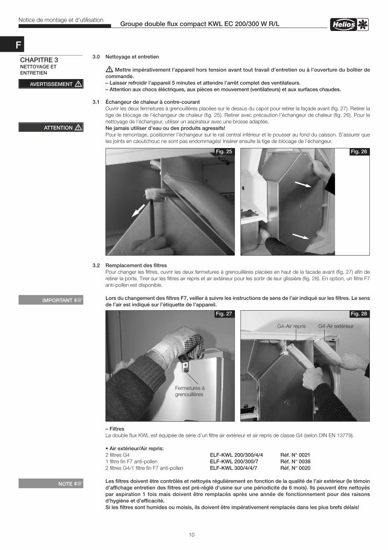
3.0 Nettoyage et entretien
� Mettre impérativement l’appareil hors tension avant tout travail d’entretien ou à l’ouverture du boîtier decommande.– Laisser refroidir l’appareil 5 minutes et attendre l’arrêt complet des ventilateurs.– Attention aux chocs éléctriques, aux pièces en mouvement (ventilateurs) et aux surfaces chaudes.
3.1 Échangeur de chaleur à contre-courantOuvrir les deux fermetures à grenouillères placées sur le dessus du capot pour retirer la façade avant (fig. 27). Retirer latige de blocage de l’échangeur de chaleur (fig. 25). Retirer avec précaution l’échangeur de chaleur (fig. 26). Pour lenettoyage de l’échangeur, utiliser un aspirateur avec une brosse adaptée. Ne jamais utiliser d’eau ou des produits agressifs!Pour le remontage, positionner l’échangeur sur le rail central inférieur et le pousser au fond du caisson. S’assurer queles joints en caoutchouc ne sont pas endommagés! Insérer ensuite la tige de blocage de l’échangeur.
3.2 Remplacement des filtresPour changer les filtres, ouvrir les deux fermetures à grenouillères placées en haut de la facade avant (fig. 27) afin deretirer la porte. Tirer sur les filtres air repris et air extérieur pour les sortir de leur glissière (fig. 28). En option, un filtre F7anti-pollen est disponible.
Lors du changement des filtres F7, veiller à suivre les instructions de sens de l’air indiqué sur les filtres. Le sensde l’air est indiqué sur l’étiquette de l’appareil.
– FiltresLa double flux KWL est équipée de série d’un filtre air extérieur et air repris de classe G4 (selon DIN EN 13779). • Air extérieur/Air repris:2 filtres G4 ELF-KWL 200/300/4/4 Réf. N° 00211 filtre fin F7 anti-pollen ELF-KWL 200/300/7 Réf. N° 00382 filtres G4/1 filtre fin F7 anti-pollen ELF-KWL 300/4/4/7 Réf. N° 0020 Les filtres doivent être contrôlés et nettoyés régulièrement en fonction de la qualité de l’air extérieur (le témoind’affichage entretien des filtres est pré-réglé d’usine sur une périodicité de 6 mois). Ils peuvent être nettoyéspar aspiration 1 fois mais doivent être remplacés après une année de fonctionnement pour des raisonsd'hygiène et d'efficacité. Si les filtres sont humides ou moisis, ils doivent être impérativement remplacés dans les plus brefs délais!
Fig. 27 Fig. 28
Fermetures àgrenouillères
NOTE �
G4-Air extérieur
10
Groupe double flux compact KWL EC 200/300 W R/LNotice de montage et d’utilisation
AVERTISSEMENT �
CHAPITRE 3NETTOYAGE ETENTRETIEN
Fig. 25 Fig. 26
IMPORTANT �
G4-Air repris
ATTENTION �
F
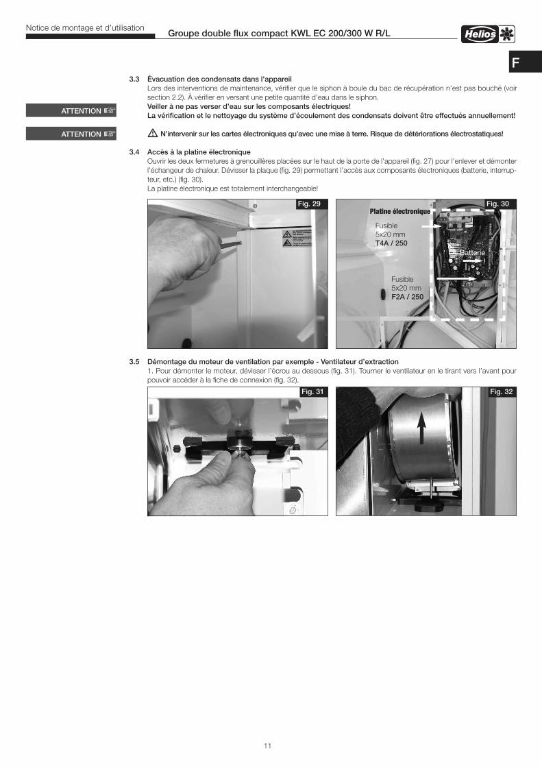
3.3 Évacuation des condensats dans l'appareilLors des interventions de maintenance, vérifier que le siphon à boule du bac de récupération n’est pas bouché (voirsection 2.2). À vérifier en versant une petite quantité d’eau dans le siphon.Veiller à ne pas verser d’eau sur les composants électriques!La vérification et le nettoyage du système d’écoulement des condensats doivent être effectués annuellement!
� N’intervenir sur les cartes électroniques qu’avec une mise à terre. Risque de détériorations électrostatiques!
3.4 Accès à la platine électroniqueOuvrir les deux fermetures à grenouillères placées sur le haut de la porte de l’appareil (fig. 27) pour l’enlever et démonterl’échangeur de chaleur. Dévisser la plaque (fig. 29) permettant l’accès aux composants électroniques (batterie, interrup-teur, etc.) (fig. 30).La platine électronique est totalement interchangeable!
3.5 Démontage du moteur de ventilation par exemple - Ventilateur d’extraction1. Pour démonter le moteur, dévisser l’écrou au dessous (fig. 31). Tourner le ventilateur en le tirant vers l’avant pourpouvoir accéder à la fiche de connexion (fig. 32).
11
Groupe double flux compact KWL EC 200/300 W R/LNotice de montage et d’utilisation
Fig. 30Fig. 29
ATTENTION �
Fig. 32Fig. 31
Platine électronique
ATTENTION �
Fusible5x20 mmT4A / 250
Fusible5x20 mmF2A / 250
Batterie
F
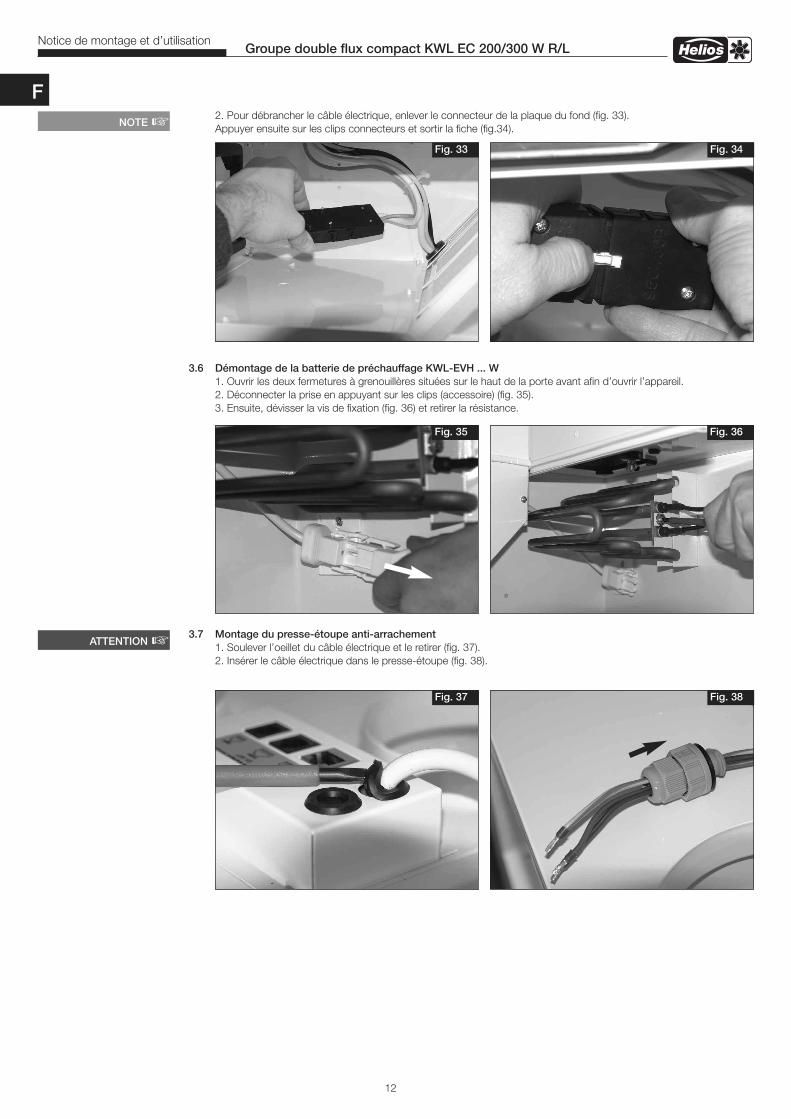
2. Pour débrancher le câble électrique, enlever le connecteur de la plaque du fond (fig. 33).Appuyer ensuite sur les clips connecteurs et sortir la fiche (fig.34).
3.6 Démontage de la batterie de préchauffage KWL-EVH ... W1. Ouvrir les deux fermetures à grenouillères situées sur le haut de la porte avant afin d’ouvrir l’appareil. 2. Déconnecter la prise en appuyant sur les clips (accessoire) (fig. 35). 3. Ensuite, dévisser la vis de fixation (fig. 36) et retirer la résistance.
3.7 Montage du presse-étoupe anti-arrachement1. Soulever l’oeillet du câble électrique et le retirer (fig. 37).2. Insérer le câble électrique dans le presse-étoupe (fig. 38).
Fig. 35 Fig. 36
12
Groupe double flux compact KWL EC 200/300 W R/LNotice de montage et d’utilisation
Fig. 33 Fig. 34
NOTE �
Fig. 37 Fig. 38
ATTENTION �
F

13
Groupe double flux compact KWL EC 200/300 W R/LNotice de montage et d’utilisation
3. Presse-étoupe avec méplat (fig. 39). 4. Introduire le presse-étoupe de biais dans l’ouverture (fig. 40).
5. Serrer les contre-écrous (fig. 41). 6. Presse-étoupe monté avec câble (fig. 42).
3.8 Accessoires diversKWL-BE Réf. N° 4265 Commutateur à 3 positions (encastré) avec voyant de fonctionnementKWL-BEC Réf. N° 4263 Commande à distance (encastré) avec câble de 3 m de long.KWL-APG Réf. N° 4270 Boîtier de montage (apparent)KWL-EM Réf. N° 4269 Module d’extensionKWL-KNX Réf. N° 4275 Module KNX/EIB (pour le raccordement sur GTB)
KWL-LTK Réf. N° 9644 Sonde de température de gaine pour batterie de chauffeKWL-CO2 Réf. N° 4272 Sonde CO2 pour mesurer le taux de concentration de CO2 dans l’airKWL-FTF Réf. N° 4273 Sonde d’hygrométrie pour mesurer le taux d’hygrométrieKWL-VOC Réf. N° 4274 Sonde COV pour mesurer le taux de COV
KWL-EVH 200/300 W Réf. N° 4224 Batterie électrique antigel 1,0 kW, pour intégration dans l’appareil EHR-R 1.2/125 Réf. N° 9433 Batterie électrique 1,2 kW, ø 125 mmWHR 125 Réf. N° 9480 Batterie eau chaude pour conduit standard, ø 125 mm WHSH 1100 24V (0-10V) Réf. N° 8819 Module hydraulique pour batterie eau chaudeWHST 300 T38 Réf. N° 8817 Kit de régulation pour batterie eau chaude
3.9 Connexions possibles avec modules d’extensions pour batterie chaude– électriqueKWL-EM
+ EHR-R 1,2/125 + KWL-LTK
– eau chaudeKWL-EM
+ WHSH 1100 24V (0-10V) + KWL-LTK + WHR 125
WHR 125 + WHST 300 T38
Fig. 39 Fig. 40
Fig. 41 Fig. 42
Méplat
1x
F

14
Groupe double flux compact KWL EC 200/300 W R/LNotice de montage et d’utilisation
Dim. en mm
KWL EC 200 W R Version droite Fig. 43
4.0 DimensionsCHAPITRE 4
DIMENSIONS
Dim. en mm
KWL EC 200 W L Version gauche Fig. 44
Dim. en mm
KWL EC 300 W R Version droite Fig. 45
Dim. en mm
KWL EC 300 W L Version gauche Fig. 46
F
air rejeté
air rejeté
air rejeté
air rejeté
air soufflé
air soufflé
air soufflé
air souffléair extérieur
air extérieur
air extérieur
air extérieurair repris
air repris
air repris
air repris
siphon à boule
siphon à boule
siphon à boule
siphon à boule
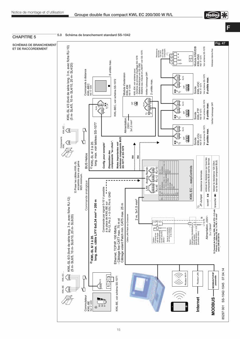
85
29
7 0
01
S
S-1
04
2-1
04
5
07
.04
.14
RJ-4
5R
J-1
2R
J-1
0
PIN
LA
NA
nalo
giq
ue
Num
ériq
ue
1TX
++
24,5
V/
Im
ax
1A
+24,5
V/
Im
ax
1A
2TX
-0
-10
VV
itesse
ventila
t.B
US
A
3R
X+
3,9
-5,9
VO
ffset
BU
SB
4TC
LE
Dro
uge
GN
D
5R
CLE
Dvert
x
6R
X-
GN
Dx
7lib
rex
x
8G
ND
xx
KW
LE
C .
.. e
asy
Co
ntr
ols
18
16
14
LA
NA
na
log
Nu
mé
r.
Alim
en
tatio
n,
230V
~3 x
1,5
mm
²
L1
N
Optio
n:
Inte
rrupte
ur
bip
ola
ire
On/o
ff sw
itch
DIN
EN
60335-1
7.1
2.2
(fourn
iture
clie
nt)
PE
Sig
nal d
e c
om
mande,
voir n
otic
e d
’util
isatio
net de m
onta
ge
Optio
n:
À p
révo
ir e
nca
s de foye
ratm
osp
hérique
ouve
rt (
fourn
it.clie
nt)
!
2 m
, 3
x1
,5 m
m²
Eth
ern
et,
TC
P/I
P,
- C
âb
lag
e f
ixe
CA
T7
ma
x.
75
m e
tC
âb
lag
e v
ola
nt
Pa
tch
min
. C
AT
5 m
ax.
25
m
10
0 M
bit/s
,
KW
L-S
L6
/3 (
livré
de
sé
rie
lo
ng
. 3
m,
ave
c f
ich
e R
J-1
2)
(5 m
- S
L6
/5,
10
m-
SL
6/1
0,
20
m-
SL
6/2
0)
KW
L-S
L4
/3 (
)(5
m-
SL
4/5
, 1
0 m
- S
L4
/10
, 2
0 m
- S
L4
/20
)liv
ré d
e s
érie
lo
ng
. 3
m,
ave
c f
ich
e R
J-1
0
KW
L-S
L4
/ 3
à 2
0.
lon
g.
ma
x.
vo
ir t
ab
lea
u S
S-1
07
7
BU
S H
elio
sC
om
muta
teur
KW
L-B
ER
éf.
N°
42
65
RJ1
2
12
3
16
S1
S2
S3
Câble
LA
N P
atc
h o
u C
rossover
KW
L-B
E,
vo
ir s
ch
ém
a S
S-1
07
1
16
16
KW
L-B
E
16
KW
L-E
C ...
Ro
ute
ur
Wi-F
i
Co
mm
an
de
à d
ista
nce
KW
L-B
EC
Ré
f. N
° 4
26
3
14
14
JP
-Ju
mp
er
résis
tance term
inale
.
ou
ve
rt
bra
nch
é
enle
ver
la r
ésis
tance s
ur
tous les
com
posants
BU
S s
auf le
dern
ier.
lais
ser
la r
ésis
tance 1
20 O
hm
sur
le d
ern
ier
com
posant B
US
.
RJ10
JP
8 u
nité
s m
ax.
KW
L-B
EC
, vo
ir s
ch
ém
a S
S-1
07
2
14C
om
posants
KW
LK
WL-E
C ...
14
14
14
RJ10
JP
14
Mo
du
le d
’exte
nsio
nK
WL
-EM
42
69
Ré
f. N
°
2 u
nité
s m
ax.
KW
L-E
M,
voir s
chém
a p
our:
- S
chém
a d
e p
rincip
e c
hauffage S
S-1
078
- B
att
erie é
lectr
ique v
oir S
S-1
069
- B
att
erie e
au c
haude e
t L/S
EW
Tvoir S
S-1
070
Vérifier
l’adre
ssage D
IP!
Co
mm
and
e a
nalo
giq
ue
14
14
14
RJ10
RJ10
RJ10
JP
JP
JP
14
14
14
1
off
on
2
DIP
DIP
DIP
DIP
1
off
on
23
41
off
on
23
41
off
on
23
4
So
nd
eK
WL
-CO
24
27
2R
éf.
N°
So
nd
eK
WL
-FT
F4
27
3R
éf.
N°
So
nd
eK
WL
-VO
C4
27
4R
éf.
N°
Voir s
chém
a S
S-1
073
Vérifier
l’adre
ssage D
IP!
Voir s
chém
a S
S-1
074
Voir s
chém
aS
S-1
075
8 u
nit
és
ma
x.
8 u
nit
és
ma
x.
8 u
nit
és
ma
x.
Co
nfi
g.
po
ur
ex
em
ple
!
Dis
po
sit
ion
de
sc
om
po
sa
nts
“a
u c
ho
ix”.
No
tes
im
po
rta
nte
s v
oir
sc
hé
ma
s c
om
po
sa
nts
BU
SS
S-1
07
7 e
t S
S-1
07
9
Mo
du
le K
NX
/EIB
KW
L-K
NX
42
75
Ré
f. N
°
Voir s
chém
aS
S-1
076
Adre
sse inte
rne fix
e
+24 V
GND
A
B
1
4
2
3
+-R
ésis
tance
term
inale
120 O
hm
sur
dern
ier
com
posant
Alim
en
tatio
n,
230V
~
3x1,5
mm
²
1)
1)
1)
1)
1)
1)
2)
2)
Po
se
r le
s c
âb
les K
WL
-SL
en
ca
str
és d
an
s u
ne
ga
ine
M2
5 m
inim
um
.
Ro
ute
ur
LA
NIn
tern
et
KW
L-S
L6
/ 3
à 2
0.
lon
g.m
ax
. c
âb
le L
iYY
6x
0,3
4 m
m²
= 2
00
m
2)
MO
DB
US
/TC
P/I
Pp
as
se
rell
eM
OD
BU
S3)
Co
ura
nt
de f
uit
e s
ur
KW
L500 e
t 370
Pré
vo
ir 2
x c
âb
les
> 3
,5 m
A.
PE
ou
1 x
PE
> 1
0 m
m²
selo
n D
IN E
N 5
0178
3)
ou
ou
Com
mande p
ar
sig
nal 0-1
0 V
possib
leà la p
lace d
e K
WL-B
E s
ur
RJ-1
2, P
in 2
: +
0-1
0V
, P
in 6
: G
ND
RJ-4
5R
J-1
2R
J-1
0
15
Groupe double flux compact KWL EC 200/300 W R/LNotice de montage et d’utilisation
5.0 Schéma de branchement standard SS-1042
Fig. 47
CHAPITRE 5
SCHÉMAS DE BRANCHEMENTET DE RACCORDEMENT
F
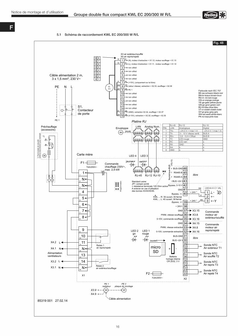
16
Groupe double flux compact KWL EC 200/300 W R/LNotice de montage et d’utilisation
Carte mère
T4A/250V~
Relais 1air repris/rejeté
85319 001 27.02.14
N
14
13
N
11
10
9
8
7
6
5
4
N
N
146454443424140
393837363534333231302928272625242322
F2A/250V~
1
2
3
4
5
6
7
8
9
10
11
12
13
14
15
Relais 2air extérieur/soufflage
RJ-12 RJ-10RJ-4518 16 14
Pro
gra
mm
atio
n
BUS-GNDN
um
érique-B
US
4
RS485-B3
RS485-A2
BUS +24 V1
Bypass, 0-10 V
GND
Bypass, +/-
+ 24V=
GND
PWM, vitesse soufflage
0-10V, commande soufflage
GND
PWM, vitesse extraction
0-10V, commande extraction
BUS-GND
BUS +24 Vlibre
libre
PE 1radiateur
X3.9
PE 2plaque de montage
Bypass, +/-
Platine RJ
18 16 14
LAN Analog Num.
18 16 14
Câble alimentation
rougegnLED 2 LED 1
vertjaune
LED 4 LED 3
RJ-45 RJ-12 RJ-10
PIN LAN Analogique Digital
1 TX+ +24,5 V / I max 1 A +24,5 V / I max 1 A
2 TX- 0 - 10 V vitesse ventil. BUS A
3 RX+ 3,9 - 5,9 V Offset BUS B
4 TC LED rouge GND
5 RC LED vert x
6 RX- GND x
7 frei x x
8 GND x x
F1
F2
Enveloppeblindé
microSD
ouvert
Batteriehorloge interneCR 2032, 3 V
+ -
(=R
J-10
)
JP1 Jumper ponté= 120 Ohm activeÀ enlever en cas d’utilisationdes bornes 43/44/45/46.
Standard usine:
résistance terminale
Sonde NTCAir soufflé T2
Sonde NTCAir extérieur T1
Sonde NTCAir rejeté T4
Sonde NTCAir repris T3
Commandechauffage 230V~,max. 2,4 kW
Préchauffage(accessoire)
1 N
1)
1)
Th
erm
ost
ats
de
sé
curité
sch
ém
a b
ran
che
me
nt
po
ur
exe
mp
le
123
-+~+~Y
LM24A-K-C1 VAL
1
0
+ 24V *
+ 24V *
ws
rt
sw
Farbcode nach IEC 757BK-sw-schwarz-black-noirBN-br-braun-brown-brunRD-rt- rot-red-rougeOG-or-orange-orangeYE-ge-gelb-yellow-jauneGN-gn-grün-green-vertBU-bl-blau-blue-bleuVT-vi-violett-violett-violetGY-gr-grau-grey-grisWH-ws-weiß-white-blancPK-rs-rosa-pink-rose
N LPE
S1,Contacteurde porte
Câble alimentation 2 m,3 x 1,5 mm², 230 V~
PE 1
12
910
34
1112
56
1314
78
1516
1
2
9
10
3
4
11
12
5
6
13
14
7
8
15
16
X3 air extérieur/souffléX4 air repris/rejeté
(N), X1.12,moteur d’extraction = = X1.15moteur soufflage
(L), = X1.11, = X1.14moteur d’extraction moteur soufflage
non utilisé
non utilisé
PE 1
non utilisé
non utilisé
non utilisé
(+10V), (uniquement sur la fiche)
(retour vitesse), X2.33,extraction = soufflage = X2.36
(GND), X2.34,extraction soufflage = X2.37
(0-10V), = X2.32,extraction soufflage = X2.35
M
EC
rt
ws
bl
ge
bl
br
gn
gn
ge
br
ws
gn
bl
br
non utilisé
non utilisé
non utilisé
non utilisé
X1X2
Commandemoteur airrepris/rejeté
Commandemoteur airextérieur/soufflé
X3.15
X3.8
X3.16
X4.15
X4.8
X4.16
Alimentationventilateurs
X3.2
L
L
N
NX3.1
X4.2
X4.1
X4.9
KWL ... R: 39 ouvert, 40 ferméKWL ... L: 40 ouvert, 39 fermé*
5.1 Schéma de raccordement KWL EC 200/300 W R/L
Fig. 48
F
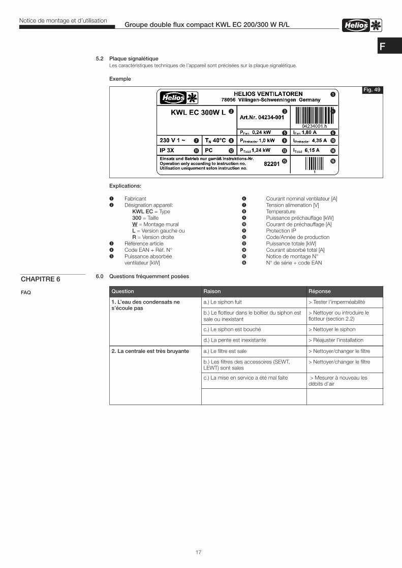
17
Groupe double flux compact KWL EC 200/300 W R/LNotice de montage et d’utilisation
5.2 Plaque signalétique Les caractéristiques techniques de l’appareil sont précisées sur la plaque signalétique.
Exemple
Explications:
q Fabricant y Courant nominal ventilateur [A]w Désignation appareil: u Tension alimenation [V] KWL EC = Type i Temperature 300 = Taille o Puissance préchauffage [kW] W = Montage mural a Courant de préchauffage [A] L = Version gauche ou s Protection IP R = Version droite d Code/Année de productione Référence article f Puissance totale [kW]r Code EAN + Réf. N° g Courant absorbé total [A]t Puissance absorbée h Notice de montage N° ventilateur [kW] j N° de série + code EAN
6.0 Questions fréquemment poséesCHAPITRE 6
FAQ Question Raison Réponse
1. L’eau des condensats nes’écoule pas
a.) Le siphon fuit > Tester l’imperméabilité
b.) Le flotteur dans le boîtier du siphon estsale ou inexistant
> Nettoyer ou introduire leflotteur (section 2.2)
c.) Le siphon est bouché > Nettoyer le siphon
d.) La pente est inexistante > Réajuster l’installation
2. La centrale est très bruyante a.) Le filtre est sale > Nettoyer/changer le filtre
b.) Les filtres des accessoires (SEWT,LEWT) sont sales
> Nettoyer/changer le filtre
c.) La mise en service a été mal faite > Mesurer à nouveau lesdébits d’air
Fig. 49q
w e r
u it yo a
s d f g
h j
F

Service et informationsD HELIOS Ventilatoren GmbH + Co KG · Lupfenstraße 8 · 78056 VS-Schwenningen F HELIOS Ventilateurs · Le Carré des Aviateurs · 157 avenue Charles Floquet · 93155 Le Blanc Mesnil CedexCH HELIOS Ventilatoren AG · Tannstrasse 4 · 8112 Otelfingen GB HELIOS Ventilation Systems Ltd. · 5 Crown Gate · Wyncolls Road · Severalls Industrial Park · A HELIOS Ventilatoren · Postfach 854 · Siemensstraße 15 · 6023 Innsbruck Colchester · Essex · CO4 9HZ
www.helios-fr.comllustrations non contractuellesConservez la notice à proximité de l’appareil N° Réf. 82201/11.14