Embed Size (px)
Citation preview
ma_
msh
_fw
_190
117
Hauff-Technik GmbH & Co. KG
Robert-Bosch-Straße 9
89568 Hermaringen, GERMANY
Tel. +49 7322 1333-0
Fax +49 7322 1333-999
www.hauff-technik.de
Art
. Nr.:
509
0032
034
Rev.:
00/2
019-
01-1
7
Vor Beginn der Montage Anweisung lesen und gut aufbewahren!
www.hauff-technik.de
Immer. Sicher. Dicht.Immer. Sicher. Dicht.
2Art. Nr.: 5090032034 Rev.: 00/2019-01-17
Montageanweisung - MSH-FW Basic DE
MSH-FW Basic mit Modul 1
MSH-FW Basic
87
6
1
1
1 2 3 4 5
6
2
5421 6
7
8
3
4
1 2 54
7
8
3 6
5
1 2 53 4
8
7
6
3
1 2 4
6
3 5
Art. Nr.: 5090032034 Rev.: 00/2019-01-17Art. Nr.: 5090032034 Rev.: 00/2019-01-17 Art. Nr.: 5090032034 Rev.: 00/2019-01-17 2143
ENNotizen / NotesMSH-FW Basic
14
1211
15
9
16
10
13
MSH-FW Basic
19
21
17 18
20
22
23 24
Art. Nr.: 5090032034 Rev.: 00/2019-01-17Art. Nr.: 5090032034 Rev.: 00/2019-01-17 Art. Nr.: 5090032034 Rev.: 00/2019-01-17 2143
ENNotizen / NotesMSH-FW Basic
14
1211
15
9
16
10
13
MSH-FW Basic
19
21
17 18
20
22
23 24
5Art. Nr.: 5090032034 Rev.: 00/2019-01-17
MSH-FW Basic
25 26
27 28
6 Art. Nr.: 5090032034 Rev.: 00/2019-01-17
MSH-FW Basic
Sicherheitshinweise und Informationen
ZielgruppeDie Montage darf nur von sachkundigen Personen durchgeführt werden.Qualifi zierte und geschulte Personen für die Montage haben • die Kenntnis der allgemeinen Sicherheits- und Unfallverhütungsvorschriften in der
jeweils gültigen Fassung,• die Kenntnis in der Anwendung von Sicherheitsausrüstung,• die Kenntnis im Umgang mit Hand- und Elektrowerkzeugen,• die Kenntnis der einschlägigen Normen und Richtlinen zum Verlegen von Rohren/
Kabeln und zum Verfüllen von Leitungsgräben in der jeweils gültigen Fassung,• die Kenntnis der Vorschriften und Verlegerichtlinien des Versorgungsunterneh-
mens in der jeweils gültigen Fassung,• die Kenntnis der WU-Beton Richtlinie und der Bauwerksabdichtungsnormen in
der jeweils gültigen Fassung.
Allgemeines und VerwendungszweckUnsere Produkte sind entsprechend ihrer bestimmungsgemäßen Verwendung ausschließlich für den Einbau in Bauwerke entwickelt, deren Baustoffe dem derzei-tigen Stand der Technik entsprechen. Für eine andere oder darüber hinaus gehende Verwendung, sofern sie nach Rücksprache mit uns nicht ausdrücklich schriftlich bestätigt wurde, übernehmen wir keine Haftung. Die Gewährleistungsbedingungen entnehmen Sie unseren aktuellen AGB (Allgemeine Verkaufs- und Lieferbedingungen).Gas- und wasserdichte Mehrspartenhauseinführung MSH - FW Basic für die Sparten Fernwärme, Wasser, Strom und Telekommunikation zum Einbau in Kernbohrungen oder Futterrohre. Grundvariante 1 mit Innenabdichtung in 30 mm Dichtbreite und Grundvariante 2 mit Innenabdichtung 60 mm Dichtbreite, für unterkellerte Gebäude. Die Außenabdichtung ist durch Modulsysteme je nach Wandart oder Gebäudeabdichtung frei wählbar.Die MSH - FW Basic ist bei den Anwendungsbereichen wie aufstauendes Sicker-wasser, Druckwasser, WU-Beton Beanspruchungsklasse 1, DIN 18533 W2.1-E und DIN 18533 W2.2-E geeignet.Maximaler Rohraußendurchmesser für Fernwärme: Øa 110 mm (als Sonderausführung auch für Øa 125 mm lieferbar).
SicherheitDieser Abschnitt gibt einen Überblick über alle wichtigen Sicherheitsaspekte für einen optimalen Schutz des Personals sowie für einen sicheren Montageablauf.Bei Nichtbeachtung der in dieser Anweisung aufgeführten Handlungsanweisun-gen und Sicherheitshinweise können erhebliche Gefahren entstehen.Bei der Montage der Mehrspartenhauseinführung müssen die entsprechenden Vorschriften der Berufsgenossenschaften, die VDE-Bestimmungen, die entspre-chenden nationalen Sicherheits- und Unfallverhütungsvorschriften sowie die Richtlinien (Arbeits- und Verfahrensanweisungen) Ihres Unternehmens beachtet werden.Der Monteur muss die entsprechende Schutzausrüstung tragen.Es dürfen nur unbeschädigte Teile montiert werden.
Vor der Montage der Mehrspartenhauseinführung sind folgen-de Warnhinweise, Tipps und Empfehlungen zu beachten:de Warnhinweise, Tipps und Empfehlungen zu beachten:
WARNUNG!Verletzungsgefahr durch unsachgemäße Montage!Unsachgemäße Montage kann zu erheblichen Personen und Sachschäden führen.• Grundsätzlich sind die national gültigen Verlege- und Verfüllvorschriften für
Rohre und Kabel zu beachten.• Untergrund und Kabelunterbau vor der Rohr-/Kabelverlegung gut verdichten,
damit kein Absinken der Rohre/Kabel möglich ist.
HINWEIS!Keine Abdichtung durch unsachgemäße Montage!Unsachgemäße Montage kann zu Sachschäden führen.• Vor dem Einbau der Mehrspartenhauseinführung müssen der Arbeitsraum sowie
der Hausanschlussgraben nach den derzeit gültigen Richtlinien ordnungsgemäß verfüllt und verdichtet werden.
• Falsche Kabel- bzw. Schutzrohrverlegung und unsachgemäßes Verfüllen des Kabelgrabens führt zu Setzungen und kann dadurch zu Beschädigungen und Undichtigkeiten führen.
• Bei allen gemauerten Wandarten, außer Beton und WU-Beton, sind Futterrohre zu verwenden.
• Vor dem Einbau der Mehrspartenhauseinführung müssen der Arbeitsraum sowie der Hausanschlussgraben nach den derzeit gültigen Richtlinien ordnungsgemäß verfüllt und verdichtet werden.
• Die aktuelle Bauwerksabdichtungsnorm DIN 18533 für erdberührte Bauteile ist zu beachten.
• Die Mehrspartenhauseinführung darf durch Kabel bzw. Rohre nicht mechanisch belastet werden.
• Eventl. vorhandene Ausbrüche müssen nachgebessert werden.• Nicht die Außendichtfl äche der Außenabdichtung schmieren.• Hausanschlussleitungen dürfen noch nicht montiert sein.• Dämmscheibenmesser schneidet nur auf Zug.
DE• Schutzrohre, welche zwischen Gebäude und Versorgungsleitungen verlegt
werden, können an die Mantelrohre (Da = 75 mm) der MSH-FW gas- und wasserdicht angemufft werden.
• Alle Dichtungen vor der Montage umlaufend mit Gleitmittel bestreichen.• Öffnungen der Innen- und Außenabdichtung mit Gleitmittel einschmieren.• Beim Verlegen der Fernwärmeleitungen als Rollenware empfehlen wir die
zusätzliche Abdichtung der Fernwärmerohre an der Gebäudeaußenseite mit dem Manschettenstopfen MS125-FW (Montageschritt 5.9).
• Die Fernwärmerohre sind spannungsfrei zu verlegen. Ggf. empfehlen wir als Hilfsmittel für die Montage der 6-kant Schrauben eine Mutter M8 in den Steckschlüsseleinsatz einzulegen.
• Es müssen alle Dichtelemente montiert werden, auch wenn nur eine Teilbele-gung der Medien erfolgt.
• Wird vorerst keine Gasarmatur installiert, muss das mitgelieferte Blinddichte-lement montiert werden.
• Bei Temperaturen unter 5°C verzögert sich der Schrumpfprozess.• Beim Schrumpfvorgang mit einer Flamme ständig umlaufend und gleichmäßig
erwärmen, um eine örtliche Überhitzung zu vermeiden.• Für die Reinigung der Systemdeckel dürfen keine lösungsmittelhaltigen Reiniger
verwendet werden. Wir empfehlen den Kabelreiniger KR M.T.X.• Weiteres Zubehör und Informationen unter www.hauff-technik.de und in
den technischen Datenblättern.
PersonalanforderungenQualifikationen
WARNUNG!VerletzungsgefahrbeiunzureichenderQualifikation!Unsachgemäßer Umgang kann zu erheblichen Personen und Sachschäden führen.• Montage darf nur von qualifi zierten und geschulten Personen durchgeführt
werden, welche diese Montageanweisung gelesen und verstanden haben.
FachpersonalFachpersonal ist aufgrund seiner fachlichen Ausbildung, Kenntnisse und Erfahrung sowie Kenntnis der einschlägigen Bestimmungen, Normen und Vorschriften in der Lage, die ihm übertragenen Arbeiten auszuführen und mögliche Gefahren selbstständig zu erkennen und zu vermeiden.
Transport, Verpackung, Lieferumfang und Lagerung Sicherheitshinweise zum Transport Sicherheitshinweise zum Transport HINWEIS!
Beschädigungen durch unsachgemäßen Transport!Bei unsachgemäßem Transport können Sachschäden in erheblicher Höhe entstehen.• Beim Abladen der Packstücke bei Anlieferung sowie innerbetrieblichem
Transport vorsichtig vorgehen und die Symbole auf der Verpackung beachten.
TransportinspektionDie Lieferung bei Erhalt unverzüglich auf Vollständigkeit und Transportschäden prüfen.Bei äußerlich erkennbarem Transportschaden wie folgt vorgehen:• Lieferung nicht oder nur unter Vorbehalt entgegennehmen.• Schadensumfang auf den Transportunterlagen oder auf dem Lieferschein des
Transporteurs vermerken.
• Jeden Mangel reklamieren, sobald er erkannt ist.• Schadenersatzansprüche können nur innerhalb der geltenden Reklamati-
onsfristen geltend gemacht werden.
LieferumfangZum Lieferumfang der MSH-FW mit Modul 1 gehören:
1 MSH-FW Basic Grundvariante 1 - Innenabdichtung (Dichtbreite 30 mm) mit Mantelrohren
1 Außenabdichtung Modul 1 (Dichtbreite 30 mm)3 Universalabdichtelemente für Wasser, Strom und Telekommunikation2 Universalabdichtelemente für Fernwärme
Zum Lieferumfang der MSH-FW mit Modul 1 und 2 gehören:1 MSH-FW Basic Grundvariante 1 - Innenabdichtung (Dichtbreite 30 mm) mit
Mantelrohren1 Außenabdichtung Modul 1 (Dichtbreite 30 mm)1 Außenfl ansch Modul 23 Universalabdichtelemente für Wasser, Strom und Telekommunikation2 Universalabdichtelemente für Fernwärme
Zum Lieferumfang der MSH-FW mit Modul 1 und 3 gehören:1 MSH-FW Basic Grundvariante 1 - Innenabdichtung (Dichtbreite 30 mm) mit
Mantelrohren1 Außenabdichtung Modul 1 (Dichtbreite 30 mm)1 Perimeterdämmscheibe Modul 33 Universalabdichtelemente für Wasser, Strom und Telekommunikation2 Universalabdichtelemente für Fernwärme
6 7Art. Nr.: 5090032034 Rev.: 00/2019-01-17
MSH-FW Basic
Zum Lieferumfang der MSH-FW mit Modul 5 gehören:1 MSH-FW Basic Grundvariante 1 - Innenabdichtung (Dichtbreite 30 mm) mit
Mantelrohren1 Außenabdichtung Modul 5 (Dichtbreite 30 mm)3 Universalabdichtelemente für Wasser, Strom und Telekommunikation2 Universalabdichtelemente für Fernwärme
Zum Lieferumfang der MSH-FW mit Modul 6 gehören:1 MSH-FW Basic Grundvariante 1 oder 2 - Innenabdichtung (Dichtbreite 30
oder 60 mm) mit Mantelrohren1 Außenabdichtung Modul 6 (Dichtbreite 90 mm)3 Universalabdichtelemente für Wasser, Strom und Telekommunikation2 Universalabdichtelemente für Fernwärme
LagerungHINWEIS!Beschädigungen durch unsachgemäße Lagerung!Bei unsachgemäßer Lagerung können Sachschäden in erheblicher Höhe entstehen.• Mehrspartenhauseinführung vor der Montage vor Beschädigungen, Feuchte und
Verunreinigungen schützen. Es dürfen nur unbeschädigte Teile montiert werden.• Die Lagerung der Mehrspartenhauseinführung muss so erfolgen, dass sie zu
keinen niederen Temperaturen (<5° C) und höheren Temperaturen (>30° C) sowie keiner direkten Sonneneinstrahlung ausgesetzt ist.
EntsorgungSofern keine Rücknahme- oder Entsorgungsvereinbarung getroffen wurde, zerleg-te Bestandteile nach sachgerechter Demontage der Wiederverwertung zuführen:• Metallische Materialreste nach den geltenden Umweltvorschriften verschrotten.• Elastomere nach den geltenden Umweltvorschriften entsorgen.• Kunststoffe nach den geltenden Umweltvorschriften entsorgen.• Verpackungsmaterial nach den geltenden Umweltvorschriften entsorgen.
Safety instructions and information
Target groupThe installation may only be carried out by technical experts.Qualifi ed and trained individuals carrying out installation must have • knowledge of general safety and accident prevention regulations as amended,• knowledge of how to use safety equipment,• knowledge of how to use hand tools and electric tools,• knowledge of the relevant standards and guidelines for laying pipes/cables and
for backfi lling utility trenches, as amended,• knowledge of the regulations and installation guidelines of the supply company
as amended,• knowledge of the waterproof concrete directive and building waterproofi ng
standards as amended.
General information and intended useIn line with their intended use, our products have been developed solely for instal-lation in buildings made of state-of-the-art materials. Insofar as no express written confi rmation has been provided by us, we do not accept any liability for any other purposes or purposes going beyond the above. For warranty conditions, please see our current General Terms and Delivery Conditions.Gastight and watertight multiple-service building entry system MSH - FW Basic for district heating, gas, water, power and telecommunications services for installation in core drills or wall sleeves. Basic variant 1 with internal sealing in 30 mm sealing width and basic variant 2 with internal sealing 60 mm in sealing width for buildings with a basement. The external sealing can be freely selected by means of the module system used, depending on the wall type or building sealing.MSH - FW Basic is suitable for application areas such as standing seepage water, pres-surised water, Class 1 waterproof concrete, DIN 18533 W2.1-E and DIN 18533 W2.2-E.Maximum outside pipe diameter for district heating: Øa 110 mm (also available as special version for Øa 125 mm).
SafetyThis section provides an overview of all the main safety aspects for optimum protection of personnel and a safe installation process.If there is a failure to observe the instructions and safety information set out here, this may result in signifi cant hazards.When installing the multiple-service building entry system it is imperative to ob-serve the relevant professional association rules, the VDE provisions, the relevant national safety and accident prevention regulations and your company’s guidelines (work and procedure instructions).The fi tter must wear the relevant protective clothing.Only intact components may be installed.
The following instructions are to be observed prior to installa-tion of the multiple-service building entry system:tion of the multiple-service building entry system:
WARNING!Risk of injury in the event of improper installation!
EN
Improper installation can result in signifi cant bodily harm and property damage.• The nationally applicable laying and fi lling regulations for pipes and cables are
to be observed at all times.• Seal the underground and cable substructure well prior to laying pipes/cables
so that the latter cannot subside.
IMPORTANT!No sealing due to incorrect installation!Improper installation can result in damage.• Before installing the multiple-service building entry system, the work space
and building entry trench must be properly fi lled and compressed in line with the currently valid directives.
• Incorrect cable/duct installation and improper fi lling of the cable trench results in subsidence and can therefore potentially cause damage and leaks.
• Wall sleeves are to be used for all wall types except for concrete and water-proof concrete.
• Before installing the multiple-service building entry system, the work space and building entry trench must be properly fi lled and compressed in line with the currently valid directives.
• The current building waterproofi ng standard DIN 18533 for underground structural components is to be observed.
• The multiple-service building entry system may not be subjected to mechanical load caused by cables or pipes.
• Any existing breaks must be reworked.• Do not lubricate the external sealing surface of the external sealing.• Building connection lines may not yet be mounted.• Insulation plate knife only cuts under tension.• Cable ducts installed between the building and supply lines can be connected
the sleeve pipes (diameter = 75 mm) of the MSH-FW to ensure a gastight and watertight link.
• Spread lubricant around all seals prior to installation.• Apply lubricant to the openings of the internal and external sealing.• When installing district heating lines as a role commodity, we additionally
recommend sealing the district heating pipes on the outside of the building using the sleeve caps MS125-FW (installation stage 5.9).
• The district heating pipes must be installed in a tension-free state. If necessary we recommend inserting an M8 screw in the socket wrench as an aid to installing the hexagonal screws.
• All sealing elements must be installed, even if only some of the media channels are to be used.
• If no gas fi tting is to be installed for the time being, the blind sealing element included must be fi tted.
• The shrinking process is delayed at temperatures under 5°C.• Apply a fl ame all around for constant, even warming during the shrinking
operation so as to avoid any local overheating.• No cleaning agents containing solvent may be used to clean the system cover.
We recommend using cable cleaner KR M.T.X.• For details of other accessories and further information, see www.hauff-technik.
de and the technical specifi cation sheets.
Personnel requirementsQualifications
WARNING!Riskofinjuryincaseofinadequatequalification!Improper handling can result in signifi cant bodily harm and property damage.• Installation may only be carried out by qualifi ed and trained individuals who have
read and understood these instructions.
Skilled expertsBased on their specialist training, skills, experience and familiarity with the relevant provisions, standards and regulations, skilled experts are able to carry out the worked assigned, independently identifying and avoiding potential hazards.
Transport, packaging, scope of delivery and storage Safety instructions in connection with transport Safety instructions in connection with transport IMPORTANT!
Damage in the event of improper transport!Signifi cant damage can occur in the event of improper transport .• When unloading packaging items on delivery and in the course of in-house
transport, proceed with care and observe the symbols on the packaging.
Transport inspectionInspect the delivery immediately on receipt for completeness and transport damage.In the event of transport damage being visible from the outside, proceed as follows:• Do not accept the delivery or only do so subject to reservations.• Make a note of the extent of damage in the transport documentation or delivery
note provided by the transporter.
• Submit a claim for every defect as soon as it has been identifi ed.• Claims for damages can only be asserted within the applicable claim period.
8 Art. Nr.: 5090032034 Rev.: 00/2019-01-17
MSH-FW Basic
Delivery scopeThe MSH-FW with Module 1 is supplied with the following:
1 MSH-FW Basic - basic variant 1 - internal sealing (sealing width 30 mm) with sleeve pipes
1 external sealing Module 1 (sealing width 30 mm)3 universal sealing elements for water, power and telecommunications2 universal sealing elements for district heating
The MSH-FW with Module 1 and 2 is supplied with the following:1 MSH-FW Basic - basic variant 1 - internal sealing (sealing width 30 mm) with
sleeve pipes1 external sealing Module 1 (sealing width 30 mm)1 outer flange Module 23 universal sealing elements for water, power and telecommunications2 universal sealing elements for district heating
The MSH-FW with Module and 3 is supplied with the following:1 MSH-FW Basic - basic variant 1 - internal sealing (sealing width 30 mm) with
sleeve pipes1 external sealing Module 1 (sealing width 30 mm)1 perimeter insulating plate Module 33 universal sealing elements for water, power and telecommunications2 universal sealing elements for district heating
The MSH-FW with Module 5 is supplied with the following:1 MSH-FW Basic - basic variant 1 - internal sealing (sealing width 30 mm) with
sleeve pipes1 external sealing Module 5 (sealing width 30 mm)3 universal sealing elements for water, power and telecommunications2 universal sealing elements for district heating
The MSH-FW with Module 6 is supplied with the following:1 MSH-FW Basic - basic variant 1 or 2 - internal sealing (sealing width 30 or 60
mm) with sleeve pipes1 external sealing Module 6 (sealing width 90 mm)3 universal sealing elements for water, power and telecommunications2 universal sealing elements for district heating
StorageIMPORTANT!Damage due to improper storage!Significant damage can occur in the event of improper storage.• The multiple-service building entry system is to be protected from damage,
damp and soiling prior to installation. Only intact components may be installed.• The multiple-service building entry system must be stored in such a way that
it is not exposed to low temperatures (<5° C), high temperatures (>30° C) or direct sunlight.
DisposalIf no return or disposal agreement has been concluded, recycle dismantled components after they have been properly dismantled:• Metal remains are to be scrapped according to existing environmental
regulations.• Dispose of elastomers according to existing environmental regulations.• Dispose of plastics according to existing environmental regulations.• Dispose of packaging material according to existing environmental regulations.
8 9Art. Nr.: 5090032034 Rev.: 00/2019-01-17
MSH-FW Basic DE
Inhaltsverzeichnis
1 ImpressumCopyright © 2018 by
Hauff-Technik GmbH & Co. KG Abteilung: Technische Redaktion Robert-Bosch-Straße 9 89568 Hermaringen, GERMANY Tel. +49 7322 1333-0 Fax +49 7322 1333-999 E-Mail [email protected] Internet www.hauff-technik.de
Die Vervielfältigung der Montageanleitung - auch aus-zugsweise - als Nachdruck, Fotokopie, auf elektronischem Datenträger oder irgendein anderes Verfahren bedarf unserer schriftlichen Genehmigung.Alle Rechte vorbehalten. Technische Änderungen jederzeit und ohne jede Voran-kündigung vorbehalten.Diese Montageanweisung ist Bestandteil des Produkts.Printed in the Federal Republic of Germany
2 Symbolerklärung
1 Arbeitsschritte
Bezugsnummerierung in Zeichnungen1
► Folge/Resultat eines Arbeitsschrittes
3 Benötigtes Werkzeug und HilfsmittelFür die ordnungsgemäße Installation der Mehrsparten-hauseinführung benötigen Sie neben dem üblichen Stan-dardwerkzeug die folgenden Werkzeuge und Hilfsmittel:
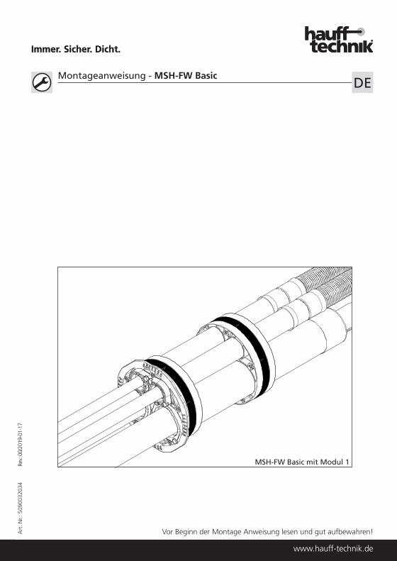
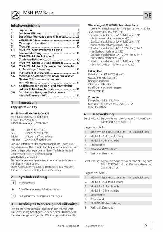
4 BeschreibungBeschreibung: Betonierte Wand (WU-Beton) mit Perimeter-
dämmung (siehe Abb.: 1).
Legende zu Abb.: 1
1 MSH-FW Basic Grundvariante 1 - Innenabdichtung
2 Modul 1 - Außenabdichtung
3 Modul 3 - Dämmscheibe
4 Mantelrohre
5 Betonwand (WU-Beton)
6 Perimeterdämmung
Beschreibung: Betonierte Wand mit Außenabdichtung nach DIN 18533 W2.1-E und Perimeterdämmung (siehe Abb.: 2).
Legende zu Abb.: 2
1 MSH-FW Basic Grundvariante 1 - Innenabdichtung
2 Modul 1 - Außenabdichtung
3 Modul 2 - Außenflansch
4 Modul 3 - Dämmscheibe
5 Mantelrohre
6 Betonwand
7 KMB-/PMBC-Beschichtung
8 Perimeterdämmung
Werkzeugset MSH/GEH bestehend aus:1 Drehmomentschlüssel 1/4“, verstellbar von 4-20 Nm3 Verlängerung, 150 mm 1/4“1 Steckschlüsseleinsatz SW 5 (M6) lang, 1/4“
(für Innensechskantschraube M6)1 Steckschlüsseleinsatz SW 6 (M8) lang, 1/4“
(für Innensechskantschraube M8)1 Steckschlüsseleinsatz SW 10 (M6) lang, 1/4“
(für Sechskantschraube M6)1 Steckschlüsseleinsatz SW 13 (M8) lang, 1/4“
(für Sechskantschraube M8)1 Steckschlüsseleinsatz SW 7 (M4) lang, 1/4“
(für Manschettenstopfen-Spannband)
Hilfsmittel:Kabelreiniger KR M.T.X. (Hauff)Gasbrenner (Heißluftfön)ReinigungslappenGleitmittel GM (Hauff)Hauff-DämmscheibenmesserWasserwaage
Zubehör:Doppelmuffe DM-DN 75-KManschettenstopfen MS75/MS125-FWKabuflex DN75
1 Impressum ...........................................................92 Symbolerklärung ................................................93 Benötigtes Werkzeug und Hilfsmittel ...............94 Beschreibung .......................................................94 Montage vorbereiten .......................................105 Montage ............................................................105.1 MSH-FW - Grundvariante 1 oder 2
(Innenabdichtung) ............................................105.2 MSH-FW - Modul1, 5 oder 6
(Außenabdichtung) ...........................................105.3 MSH-FW-Modul2(Außenflansch) .................105.4 MSH-FW - Modul 3 (Perimeterdämmscheibe)
Außenseitige Dämmung ..................................115.5 Mantelrohr-/Schutzrohr....................................115.6 Montage Spartendichtelemente für Wasser,
Elektro, Telekommunikation und Fernwärme ........................................................11
5.7 Abdichtung der Medien- und Mantelrohre auf der Gebäudeaußenseite ............................11
5.8 Dichtheitsprüfung der Mehrsparten- hauseinführung - FW ........................................11
10 Art. Nr.: 5090032034 Rev.: 00/2019-01-17
MSH-FW Basic DEBeschreibung: Doppel-/Elementwand mit Perimeterdämmung
außen (siehe Abb.: 3).
Legende zu Abb.: 3
1 MSH-FW Basic Grundvariante 1 - Innenabdichtung
2 Modul 6 - Außenabdichtung
3 Modul 3 - Dämmscheibe
4 Mantelrohre
5 Doppel-/Elementwand mit WU-Beton
6 Perimeterdämmung
Beschreibung: Doppel-/Elementwand mit Außenabdichtung nach DIN 18533 W2.1-E und Perimeterdäm-mung außen (siehe Abb.: 4).
Legende zu Abb.: 4
1 MSH-FW Basic Grundvariante 1 - Innenabdichtung
2 Modul 6 - Außenabdichtung
3 Modul 2 - Außenflansch
4 Modul 3 - Dämmscheibe
5 Mantelrohre
6 Doppel/-Elementwand
7 KMB-/PMBC-Beschichtung
8 Perimeterdämmung
Beschreibung: Doppel-/Elementwand mit Außenabdichtung nach DIN 18533 W2.1-E und Perimeterdäm-mung innen (siehe Abb.: 5).
Legende zu Abb.: 5
1 MSH-FW Basic Grundvariante 1 - Innenabdichtung
2 Modul 5 - Außenabdichtung
3 Modul 1 - Außenabdichtung
4 Modul 2 - Außenflansch
5 Mantelrohre
6 Doppel/-Elementwand
7 KMB-/PMBC-Beschichtung
8 Perimeterdämmung innen
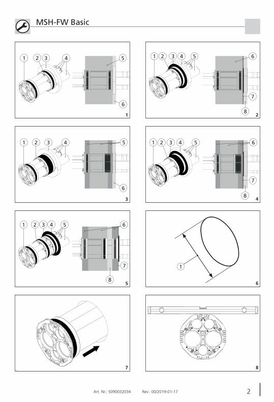
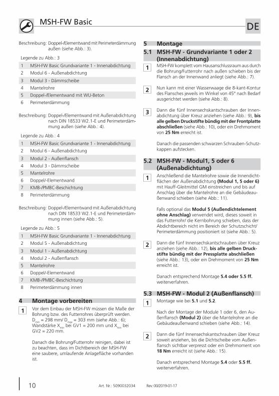
4 Montage vorbereiten
1 Vor dem Einbau der MSH-FW müssen die Maße der Bohrung bzw. des Futterrohres überprüft werden. Dmin = 298 mm/ Dmax = 303 mm (siehe Abb.: 6); Wandstärke Xmin bei GV1 = 200 mm und Xmin bei GV2 = 220 mm.
Danach die Bohrung/Futterrohr reinigen, dabei ist zu beachten, dass im Dichtbereich der MSH-FW eine saubere, umlaufende Anlagefläche vorhanden ist.
5 Montage5.1 MSH-FW - Grundvariante 1 oder 2
(Innenabdichtung)1 MSH-FW komplett vom Hausanschlussraum aus durch
die Bohrung/Futterrohr nach außen schieben bis der Flansch an der Innenwand anliegt (siehe Abb.: 7).
2 Nun kann mit einer Wasserwaage die 8-kant-Kontur des Flansches jeweils im Winkel von 45° nach Bedarf ausgerichtet werden (siehe Abb.: 8).
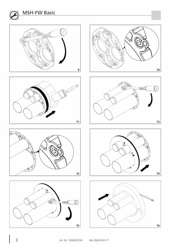
3 Dann die fünf Innensechskantschrauben der Innen-abdichtung über Kreuz anziehen (siehe Abb.: 9), bis alle gelben Druckstifte bündig mit der Frontplatte abschließen (siehe Abb.: 10), oder ein Drehmoment von 25 Nm erreicht ist.
Danach die passenden schwarzen Schrauben-Schutz-kappen aufstecken.
1 Anschließend die Mantelrohre sowie die Innendicht-flächen der Außenabdichtung (Modul 1, 5 oder 6) mit Hauff-Gleitmittel GM einstreichen und bis auf Anschlag über die Mantelrohre an die Gebäudeau-ßenwand schieben (siehe Abb.: 11).
Falls optional das Modul 5 (Außendichtelement ohne Anschlag) verwendet wird, dieses soweit in das Futterrohr/ die Kernbohrung schieben, dass der Abdichtbereich nicht im Bereich der Schutzschicht/Perimeterdämmung positioniert ist (siehe Abb.: 5).
5.2 MSH-FW - Modul1, 5 oder 6 (Außenabdichtung)
2 Dann die fünf Innensechskantschrauben über Kreuz anziehen (siehe Abb.: 12), bis alle gelben Druck-stifte bündig mit der Pressplatte abschließen (siehe Abb.: 13), oder ein Drehmoment von 25 Nm erreicht ist.
Danach entsprechend Montage 5.4 oder 5.5 ff. weiterverfahren.
1 Montage wie bei 5.1 und 5.2.
Nach der Montage der Module 1 oder 6, den Au-ßenflansch (Modul 2) über die Mantelrohre an die Gebäudeaußenwand schieben (siehe Abb.: 14).
5.3 MSH-FW-Modul2(Außenflansch)
2 Dann die fünf Innensechskantschrauben über Kreuz soweit anziehen, bis die Dichtscheibe vom Außen-flansch sichtbar verpresst oder ein Drehmoment von 18 Nm erreicht ist (siehe Abb.: 15).
Danach entsprechend Montage 5.4 oder 5.5 ff. weiterverfahren.
10 11Art. Nr.: 5090032034 Rev.: 00/2019-01-17
MSH-FW Basic DE
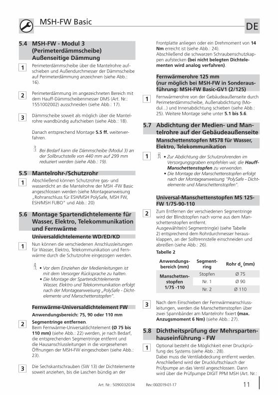
5.5 Mantelrohr-/Schutzrohr
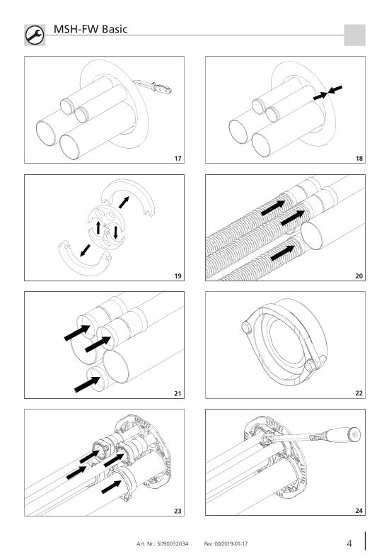
1 Abschließend können Schutzrohre gas- und wasserdicht an die Mantelrohre der MSH -FW Basic angeschlossen werden (siehe Montageanweisung „Rohranschluss für ESH/MSH PolySafe, MSH FW, ESH/MSH FUBO“ und Abb.: 20)
5.6 Montage Spartendichtelemente für Wasser, Elektro, Telekommunikation und Fernwärme
1 Nun können die verschiedenen Anschlussleitungen für Wasser, Elektro, Telekommunikation und Fern-wärme durch die Schutzrohre eingezogen werden.
• Vor dem Einziehen der Medienleitungen ist mit dem Versorger Rücksprache zu halten.
• Die Montage der Spartendichtelemente Wasser, Elektro und Telekommunikation erfolgt nach der Montageanweisung „PolySafe - Dicht-elemente und Manschettenstopfen“.
2 Segmentringe entfernen.Beim Fernwärme-Universaldichtelement (Ø 75 bis 110 mm) (siehe Abb.: 22) werden, je nach Bedarf, die entsprechenden Segmentringe entfernt und die Hausanschlussleitungen in die vorgesehenen Öffnungen der MSH-FW eingeschoben (siehe Abb.: 23).
Fernwärme-Universaldichtelement FWAnwendungsbereich: 75, 90 oder 110 mm
3 Die Sechskantschrauben (SW 13) der Dichtelemente soweit anziehen, bis die Laschen bündig an der
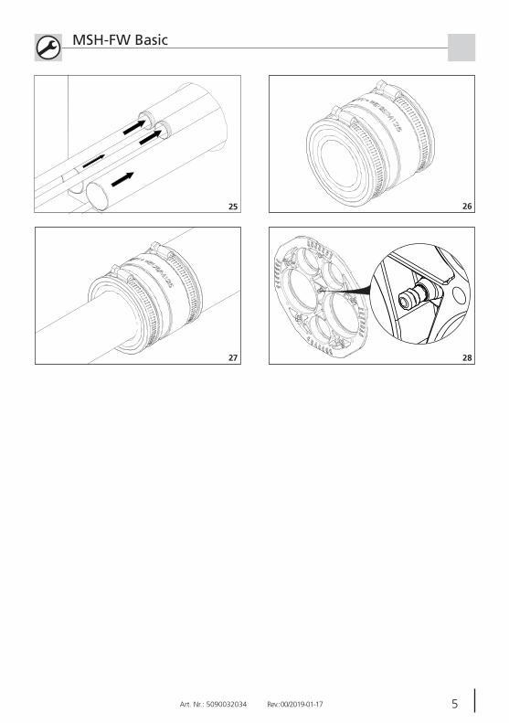
1 Fernwärmerohre von der Gebäudeaußenseite durch Perimeterdämmscheibe, Außenabdichtung (Mo-dul...) und Innenabdichtung schieben (siehe Abb.: 25). Weitere Montage siehe unter 5.1 bis 5.6.
Fernwärmerohre 125 mm(nur möglich bei MSH-FW in Sonderaus-führung: MSH-FW Basic-GV1 (2/125)
5.7 Abdichtung der Medien- und Man-telrohre auf der Gebäudeaußenseite
1 • Zur Abdichtung der Schutzrohrenden im Versorgungsgraben empfehlen wir, die Hauff-Manschettenstopfen zu verwenden.
• Die Montage der Manschettenstopfen erfolgt nach der Montageanweisung "PolySafe - Dicht-elemente und Manschettenstopfen".
2 Zum Entfernen der verschiedenen Segmentringe wird der Blindstopfen nach vorne aus dem Man-schettenstopfen entfernt.Ausgewählte(n) Segmentring(e) (siehe Tabelle 2) entsprechend dem Rohrdurchmesser heraus-klappen, an der Solltrennstelle einschneiden und abreißen (siehe Abb.: 26).
Anwendungs-bereich (mm)
Segment-ring Rohr da (mm)
Manschetten-stopfen
1/75 -110
Stopfen Ø 75
Nr. 1 Ø 90
Nr. 2 Ø 110
Tabelle 2
3 Nach dem Einschieben der Fernwärmeanschluss-leitungen, werden die Manschettenstopfen über zwei Spannbänder am Mantelrohr fi xiert (max. Anzugsmoment 6 Nm) (siehe Abb.: 27).
5.8 Dichtheitsprüfung der Mehrsparten-hauseinführung - FW
1
1 Perimeterdämmscheibe über die Mantelrohre auf-schieben und Außendurchmesser der Dämmscheibe auf Perimeterdämmung anzeichnen (siehe Abb.: 16).
2 Perimeterdämmung im angezeichneten Bereich mit dem Hauff-Dämmscheibenmesser DMS (Art. Nr.: 1551002002) ausschneiden (siehe Abb.: 17).
3 Dämmscheibe soweit als möglich über die Mantel-rohre wandbündig aufschieben (siehe Abb.: 18).
Danach entsprechend Montage 5.5 ff. weiterver-fahren.
Bei Bedarf kann die Dämmscheibe (Modul 3) an der Sollbruchstelle von 440 mm auf 299 mm reduziert werden (siehe Abb.: 19).
5.4 MSH-FW - Modul 3 (Perimeterdämmscheibe) Außenseitige Dämmung
Optional besteht die Möglichkeit einer Druckprü-fung des Systems (siehe Abb.: 28). Dabei muss die Ventilabdeckung entfernt werden.Anschließend wird der Druckluftschlauch der Prüfpumpe an das Ventil angeschlossen. Dann wird über die Prüfpumpe DIGIT PPM MSH (Art. Nr.:
Universaldichtelemente WD/ED/KD
Manschettenstopfen MS78 für Wasser, Elektro, Telekommunikation
Universal-Manschettenstopfen MS 125-FW 1/75-90-110
Frontplatte anliegen oder ein Drehmoment von 14 Nm erreicht ist (siehe Abb.: 24).Abschließend die schwarzen Schraubenschutzkap-pen aufstecken (bei nicht belegten Dichtele-menten wird analog verfahren).
12 Art. Nr.: 5090032034 Rev.: 00/2019-01-17
MSH-FW Basic DE1551001122) ein Prüfdruck von 0,5 bar aufge-bracht.
Nach einer Verweilzeit von 1 min. darf der Druck nicht unter 0,4 bar abfallen.
Nach erfolgter Prüfung kann der Prüfdruck am Ventil abgelassen werden.
12 13Art. Nr.: 5090032034 Rev.: 00/2019-01-17
MSH-FW Basic EN
Table of contents
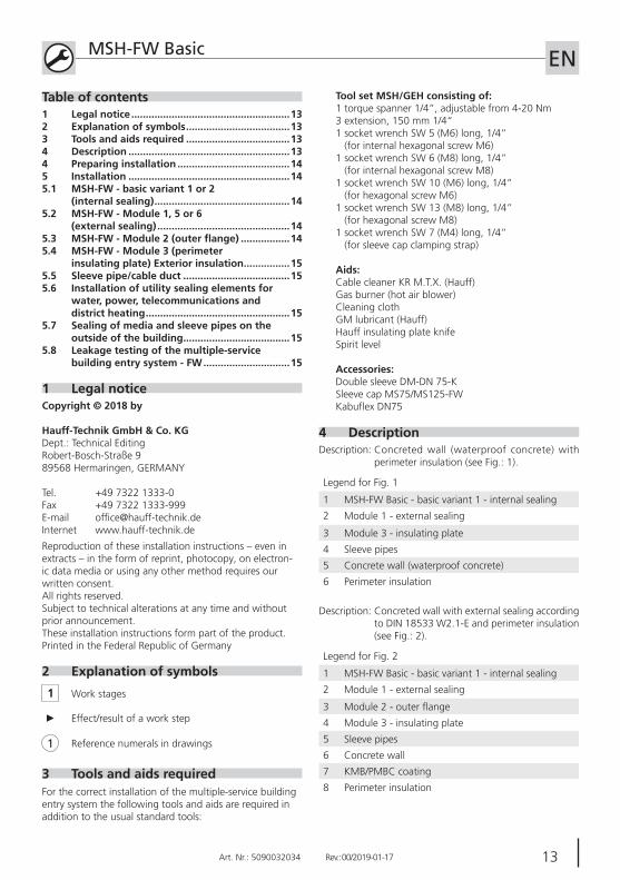
1 Legal noticeCopyright © 2018 by
Hauff-Technik GmbH & Co. KG Dept.: Technical Editing Robert-Bosch-Straße 9 89568 Hermaringen, GERMANY Tel. +49 7322 1333-0 Fax +49 7322 1333-999 E-mail [email protected] Internet www.hauff-technik.de
Reproduction of these installation instructions – even in extracts – in the form of reprint, photocopy, on electron-ic data media or using any other method requires our written consent.All rights reserved. Subject to technical alterations at any time and without prior announcement.These installation instructions form part of the product.Printed in the Federal Republic of Germany
2 Explanation of symbols
1 Work stages
Reference numerals in drawings1
► Effect/result of a work step
3 Tools and aids requiredFor the correct installation of the multiple-service building entry system the following tools and aids are required in addition to the usual standard tools:
4 DescriptionDescription: Concreted wall (waterproof concrete) with
perimeter insulation (see Fig.: 1).
Legend for Fig. 1
1 MSH-FW Basic - basic variant 1 - internal sealing
2 Module 1 - external sealing
3 Module 3 - insulating plate
4 Sleeve pipes
5 Concrete wall (waterproof concrete)
6 Perimeter insulation
Description: Concreted wall with external sealing according to DIN 18533 W2.1-E and perimeter insulation (see Fig.: 2).
Legend for Fig. 2
1 MSH-FW Basic - basic variant 1 - internal sealing
2 Module 1 - external sealing
3 Module 2 - outer flange
4 Module 3 - insulating plate
5 Sleeve pipes
6 Concrete wall
7 KMB/PMBC coating
8 Perimeter insulation
Tool set MSH/GEH consisting of:1 torque spanner 1/4”, adjustable from 4-20 Nm3 extension, 150 mm 1/4“1 socket wrench SW 5 (M6) long, 1/4”
(for internal hexagonal screw M6)1 socket wrench SW 6 (M8) long, 1/4”
(for internal hexagonal screw M8)1 socket wrench SW 10 (M6) long, 1/4”
(for hexagonal screw M6)1 socket wrench SW 13 (M8) long, 1/4”
(for hexagonal screw M8)1 socket wrench SW 7 (M4) long, 1/4”
(for sleeve cap clamping strap)
Aids:Cable cleaner KR M.T.X. (Hauff)Gas burner (hot air blower)Cleaning clothGM lubricant (Hauff)Hauff insulating plate knifeSpirit level
Accessories:Double sleeve DM-DN 75-KSleeve cap MS75/MS125-FWKabuflex DN75
1 Legal notice .......................................................132 Explanation of symbols ....................................133 Tools and aids required ....................................134 Description ........................................................134 Preparing installation .......................................145 Installation ........................................................145.1 MSH-FW - basic variant 1 or 2
(internal sealing) ...............................................145.2 MSH-FW - Module 1, 5 or 6
(external sealing) ..............................................145.3 MSH-FW-Module2(outerflange) .................145.4 MSH-FW - Module 3 (perimeter
insulating plate) Exterior insulation ................155.5 Sleeve pipe/cable duct .....................................155.6 Installation of utility sealing elements for
water, power, telecommunications and district heating ..................................................15
5.7 Sealing of media and sleeve pipes on the outside of the building .....................................15
5.8 Leakage testing of the multiple-service building entry system - FW ..............................15
14 Art. Nr.: 5090032034 Rev.: 00/2019-01-17
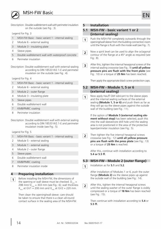
MSH-FW Basic ENDescription: Double wall/element wall with perimeter insulation
on the outside (see Fig.: 3).
Legend for Fig. 3
1 MSH-FW Basic - basic variant 1 - internal sealing
2 Module 6 - external sealing
3 Module 3 - insulating plate
4 Sleeve pipes
5 Double wall/element wall with waterproof concrete
6 Perimeter insulation
Description: Double wall/element wall with external sealing according to DIN 18533 W2.1-E and perimeter insulation on the outside (see Fig.: 4).
Legend for Fig. 4
1 MSH-FW Basic - basic variant 1 - internal sealing
2 Module 6 - external sealing
3 Module 2 - outer flange
4 Module 3 - insulating plate
5 Sleeve pipes
6 Double wall/element wall
7 KMB/PMBC coating
8 Perimeter insulation
Description: Double wall/element wall with external sealing according to DIN 18533 W2.1-E and perimeter insulation inside (see Fig.: 5).
Legend for Fig. 5
1 MSH-FW Basic - basic variant 1 - internal sealing
2 Module 5 - external sealing
3 Module 1 - external sealing
4 Module 2 - outer flange
5 Sleeve pipes
6 Double wall/element wall
7 KMB/PMBC coating
8 Perimeter insulation inside
4 Preparing installation
1 Before installing the MSH-FW, the dimensions of the opening or wall sleeve must be checked. Dmin = 298 mm/ Dmax = 303 mm (see Fig.: 6); wall thickness Xmin at GV1 = 200 mm and Xmin at GV2 = 220 mm.
Then clean the opening/wall sleeve: care should be taken to ensure that there is a clean all-round contact surface in the sealing area of the MSH-FW.
5 Installation5.1 MSH-FW - basic variant 1 or 2
(internal sealing)
1 Push the MSH-FW completely outwards through the opening/wall sleeve from the building connection room until the flange is flush with the inside wall (see Fig.: 7).
2 Now a spirit level can be used to align the octagonal contour of the flange at a 45° angle as required (see Fig.: 8).
3 After this, tighten the internal hexagonal screws of the internal sealing crosswise (see Fig.: 9) until all yellow pressurepinsareflushwiththefrontplate(see Fig.: 10) or a torque of 25 Nm has been reached.
Then apply the appropriate black screw protection caps.
1 Now apply Hauff GM lubricant to the sleeve pipes and the internal sealing surfaces of the external sealing (Module 1, 5 or 6) and push them as far as they will go via the sleeve pipes against the outside wall of the building (see Fig.: 11).
If the option of Module 5 (external sealing ele-ment without stop) has been selected, push this into the wall sleeve/core drill hole until the sealing area is not positioned in the area of the protective layer/perimeter insulation (see Fig.: 5).
5.2 MSH-FW - Module 1, 5 or 6 (external sealing)
2 Then tighten the five internal hexagonal screws crosswise (see Fig.: 12) until all yellow pressure pinsareflushwiththepressplate(see Fig.: 13) or a torque of 25 Nm is reached.
After this, continue with installation according to 5.4 or 5.5 ff.
1 Installation as for 5.1 and 5.2.
After installation of Modules 1 or 6, push the outer flange (Module 2) via the sleeve pipes up against the outside wall of the building (see Fig.: 14).
5.3 MSH-FW-Module2(outerflange)
2 After this, tighten the internal hexagonal screws until the sealing washer of the outer flange is visibly compressed or a torque of 18 Nm has been reached (see Fig.: 15).
Then continue with installation according to 5.4 or 5.5 ff.
14 15Art. Nr.: 5090032034 Rev.: 00/2019-01-17
MSH-FW Basic EN
5.5 Sleeve pipe/cable duct
1 Finally, the cable ducts can be connected to the sleeve pipes of the MSH -FW Basic in a gastight and watertight manner (see installation instructions “Pipe connection for ESH/MSH PolySafe, MSH FW, ESH/MSH FUBO“ and Fig.: 20)
5.6 Installation of utility sealing ele-ments for water, power, telecommu-nications and district heating
1 Now it is possible to feed in the various connection lines for water, power, telecommunications and district heating through the ducts.
• Consult the supplier before feeding through the media lines.
• Installation of the utility sealing elements for water, power and telecommunications is carried out according to the installation instructions “PolySafe sealing elements and sleeve caps”.
2 Remove segment rings.In the case of the district heating universal sealing element (Ø 75 bis 110 mm) (see Fig.: 22), the relevant segment rings are removed as required and the building connection lines are inserted in the MSH-FW openings provided (see Fig.: 23).
District heating universal sealing element FWArea of application: 75, 90 or 110 mm
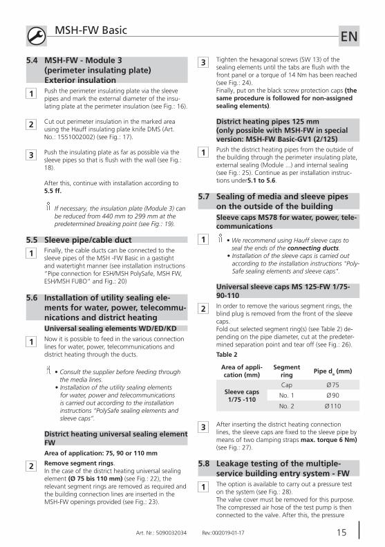
3 Tighten the hexagonal screws (SW 13) of the sealing elements until the tabs are fl ush with the front panel or a torque of 14 Nm has been reached (see Fig.: 24).Finally, put on the black screw protection caps (the same procedure is followed for non-assigned sealing elements).
1 Push the district heating pipes from the outside of the building through the perimeter insulating plate, external sealing (Module ...) and internal sealing (see Fig.: 25). Continue as per installation instruc-tions under5.1 to 5.6.
District heating pipes 125 mm(only possible with MSH-FW in special version: MSH-FW Basic-GV1 (2/125)
5.7 Sealing of media and sleeve pipes on the outside of the building
1 • We recommend using Hauff sleeve caps to seal the ends of the connecting ducts.
• Installation of the sleeve caps is carried out according to the installation instructions "Poly-Safe sealing elements and sleeve caps".
2 In order to remove the various segment rings, the blind plug is removed from the front of the sleeve caps.Fold out selected segment ring(s) (see Table 2) de-pending on the pipe diameter, cut at the predeter-mined separation point and tear off (see Fig.: 26).
Area of appli-cation (mm)
Segment ring Pipe da (mm)
Sleeve caps 1/75 -110
Cap Ø 75
No. 1 Ø 90
No. 2 Ø 110
Table 2
3 After inserting the district heating connection lines, the sleeve caps are fi xed to the sleeve pipe by means of two clamping straps max. torque 6 Nm) (see Fig.: 27).
5.8 Leakage testing of the multiple-service building entry system - FW
1
1 Push the perimeter insulating plate via the sleeve pipes and mark the external diameter of the insu-lating plate at the perimeter insulation (see Fig.: 16).
2 Cut out perimeter insulation in the marked area using the Hauff insulating plate knife DMS (Art. No.: 1551002002) (see Fig.: 17).
3 Push the insulating plate as far as possible via the sleeve pipes so that is fl ush with the wall (see Fig.: 18).
After this, continue with installation according to 5.5 ff.
If necessary, the insulation plate (Module 3) can be reduced from 440 mm to 299 mm at the predetermined breaking point (see Fig.: 19).
5.4 MSH-FW - Module 3 (perimeter insulating plate) Exterior insulation
The option is available to carry out a pressure test on the system (see Fig.: 28). The valve cover must be removed for this purpose.The compressed air hose of the test pump is then connected to the valve. After this, the pressure
Universal sealing elements WD/ED/KD
Sleeve caps MS78 for water, power, tele-communications
Universal sleeve caps MS 125-FW 1/75-90-110
16 Art. Nr.: 5090032034 Rev.: 00/2019-01-17
MSH-FW Basic ENof the test pump DIGIT PPM MSH (Art. No.: 1551001122) is raised to 0.5 bar.
After a period of 1 minute, the pressure may not drop below 0.4 bar.
Once the test is complete, the test pressure can be released at the valve.
16 17Art. Nr.: 5090032034 Rev.: 00/2019-01-17
ENNotizen / Notes
18 Art. Nr.: 5090032034 Rev.: 00/2019-01-17
ENNotizen / Notes
18 19Art. Nr.: 5090032034 Rev.: 00/2019-01-17
ENNotizen / Notes

20 Art. Nr.: 5090032034 Rev.: 00/2019-01-17
ENNotizen / Notes

Art. Nr.: 5090032034 Rev.: 00/2019-01-17Art. Nr.: 5090032034 Rev.: 00/2019-01-17 Art. Nr.: 5090032034 Rev.: 00/2019-01-17 2143
ENNotizen / NotesMSH-FW Basic
14
1211
15
9
16
10
13
MSH-FW Basic
19
21
17 18
20
22
23 24

ma_
msh
_fw
_190
117
Hauff-Technik GmbH & Co. KG
Robert-Bosch-Straße 9
89568 Hermaringen, GERMANY
Tel. +49 7322 1333-0
Fax +49 7322 1333-999
www.hauff-technik.de
Art
. Nr.:
509
0032
034
Rev.:
00/2
019-
01-1
7
Vor Beginn der Montage Anweisung lesen und gut aufbewahren!
www.hauff-technik.de
Immer. Sicher. Dicht.Immer. Sicher. Dicht.
2Art. Nr.: 5090032034 Rev.: 00/2019-01-17
Montageanweisung - MSH-FW Basic DE
MSH-FW Basic mit Modul 1
MSH-FW Basic
87
6
1
1
1 2 3 4 5
6
2
5421 6
7
8
3
4
1 2 54
7
8
3 6
5
1 2 53 4
8
7
6
3
1 2 4
6
3 5