Embed Size (px)
Citation preview
Montageanweisung
HSI150-DG zur nachträglichen Montage
GB
F
NL
PL
D
Instrukcja montażu
HSI150-DG do montażu na istniejących kablach
Montage-instructie
HSI150-DG voor montage naderhand
Instructions de montage
HSI150-DG pour un montage ultérieur
Installation Instruction
HSI150-DG for retrofitting
Ihr Scan zum Montagevideo HSI150-DG
Your scan to the installation movie
HSI150-DG
Immer. Sicher. Dicht.
2
32
1
4
8
109
3
7
65
1110a
4
12 13
8 NmHSI 150-DG-3/24-54
Beispiel/Example/Exemple/Voorbeeld/PrzykładHSI 150-DG-3/24-54
Inhalt
1 Allgemeines und Verwendungszweck2 Sicherheitshinweise3 Beschreibung4 Lieferumfang5 Benötigtes Werkzeug und Hilfsmittel6 Montage (Gebäudeaußenseite)
2 Sicherheitshinweise
Schützen Sie den Systemdeckel bei der Montageinstallation vor Beschädigungen, Feuchte und Verunreinigungen. Überprüfen Sie die Lieferung auf Vollständigkeit und alle Einzelteile auf even-tuelle Schäden. Es dürfen nur unbeschädigte Teile montiert werden.
Bei der Installation des Systemdeckels müssen die entsprechenden Vorschriften der Berufsgenossenschaf-ten, die VDE-Bestimmungen, die entsprechenden nationalen Sicherheits- und Unfallverhütungsvorschrif-ten sowie die Richtlinien (Arbeits- und Verfahrensanweisungen) Ihres Unternehmens beachtet werden.
Für die Reinigung der Kabeldurchführungen dürfen keine lösungsmittelhaltigen Reiniger verwen-det werden! Wir empfehlen Hauff-Technik Kabelreiniger M.T.X.60.
Ringraumdichtungen sind keine Festpunkte oder Lager und können somit keine mechanischen Kräfte aufnehmen. Zu erwartende Senkungen müssen durch den Einbau von Zentrierhilfen bzw. Abstandshal-tern in den Futterrohren oder Kernbohrungen ( Aluminiumflansch HSI 150-DF) aufgefangen werden.
Bei Schutzrohranschlüssen (DN100/DN125) an das System HSI 150, wird in Folge der Reduzierung des lichten Durchgangs bzw. der lichten Weite, der obere Anwendungsbereich eingeschränkt.
D
5
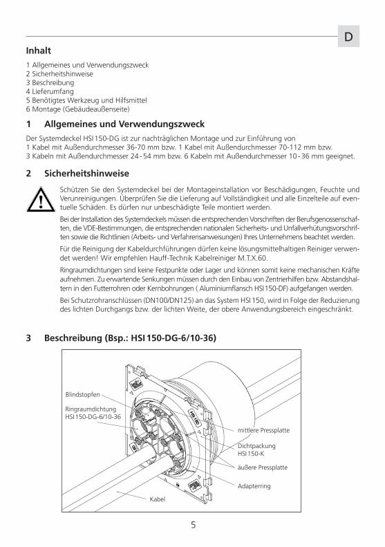
3 Beschreibung (Bsp.: HSI 150-DG-6/10-36)
Adapterring
Dichtpackung HSI 150-K
Kabel
RingraumdichtungHSI 150-DG-6/10-36
Blindstopfen
mittlere Pressplatte
äußere Pressplatte
1 Allgemeines und Verwendungszweck
Der Systemdeckel HSI 150-DG ist zur nachträglichen Montage und zur Einführung von1 Kabel mit Außendurchmesser 36-70 mm bzw. 1 Kabel mit Außendurchmesser 70-112 mm bzw.3 Kabeln mit Außendurchmesser 24 - 54 mm bzw. 6 Kabeln mit Außendurchmesser 10 - 36 mm geeignet.
Optional: 3 Stück Pressplattenabdeckungen HSI 150-PA-3/24-54 passend für HSI 150-DG-3/24-54 bzw. 1 Stück Pressplattenabdeckungen HSI 150-PA-6/10-36 passend für HSI 150-DG-6/10-36
5 Benötigtes Werkzeug und Hilfsmittel
Für die ordnungsgemäße Installation der Ringraumdichtung HRD150-DG benötigen Sie neben dem üblichen Standardwerkzeug die folgenden Werkzeuge und Hilfsmittel:
Werkzeuge:Montageset HSI 150-DG bestehend aus: 1 Drehmomentschlüssel 4-20 Nm, 1/4 Zoll 1 Verlängerung 100 mm, 1/4 Zoll 2 Verlängerungen 150 mm, 1/4 Zoll 1 Aufnahme für Akkuschrauber, Vierkant, 1/4 Zoll 1 Steckschlüsseleinsatz M6, SW 5, 1/4 Zoll 1 Steckschlüsseleinsatz M6, 100 mm lang mit Kugelkopf, 1/4 Zoll 1 Stück Gelenkstirnlochschlüssel SLS 6G (Hauff)
Hilfsmittel: 1 Stück Kabelreiniger KR60 (Hauff) 1 Stück Messschieber 1 Stück Reinigungslappen 1 Stück Akkuschrauber
6
D4 Lieferumfang
Zum Lieferumfang des Systemdeckels HSI 150-DG gehören:
1 Stück Ringraumdichtung HSI 150-DG 1 Stück Adapterring HSI 150-AR-DG 1 Stück Gleitmittelstift GM 1 Stück Messer 1 Stück Reinigungstuch
1
Legende
Arbeitsschritte
zu beachtende Hinweise
(3 Stück Blindstopfen passend für HSI 150-DG-3/24-54 bzw.6 Stück Blindstopfen passend für HSI 150-DG-6/10-36)
D
7
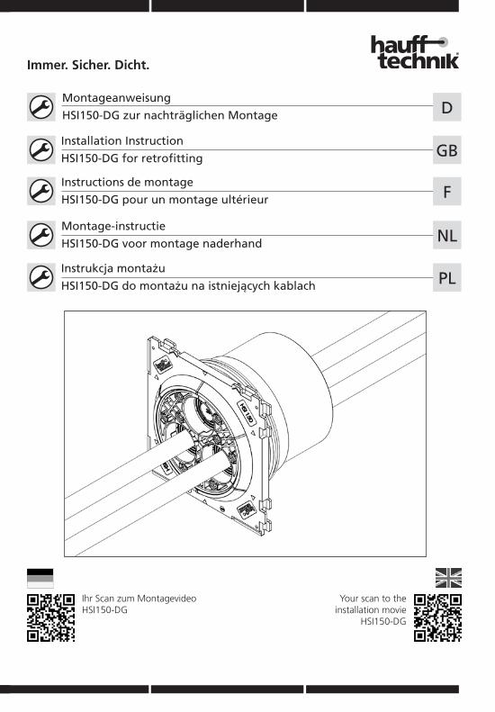
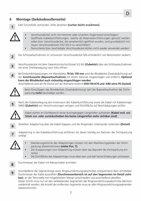
Falls Schutzfolie vorhanden, bitte abziehen (vorher leicht erwärmen).
• Verschlussdeckel nicht mit Hammer oder scharfem Gegenstand einschlagen!• Geöffnete Kabeldurchführungen, welche als Reservedurchführungen genutzt werden
sollen bzw. Verschlussdeckel, die versehentlich geöffnet wurden, sind grundsätzlich mit neuen Verschlussdeckeln HSI 150-D zu verschließen!
• Demontierte bzw. beschädigte Verschlussdeckel dürfen nicht wieder verwendet werden!
Geteilten Adapterring über die Kabel klappen und die Ringenden miteinander verbinden (Detail).
• Markierungsstriche des Adapteringes müssen mit den Markierungspfeilen der Dicht-packung übereinstimmen (siehe Pos. 7).
• Die Aussparungen vom Adapterring müssen über das Bajonett der Dichtpackung ein-rasten.
• Die Dichtfläche des Adapterringes muss eben sein und darf keine Erhebungen aufweisen.
Anschließend die Segmentringe eines Ringraumdichtungsabschnittes entsprechend dem ermittelten Durchmesser der Kabel auswählen (Durchmesserbereich ist auf den Segmenten im Detail sicht-bar), an der Trennstelle mit mitgeliefertem Messer einschneiden und anschließend abreißen.Dieser Schritt muss nun an den verbleibenden Segmenten der Ringraumdichtungsabschnitte identisch wiederholt werden; die Anzahl der entfernten Segmente muss an allen Ringraumdichtungssegmenten übereinstimmen.
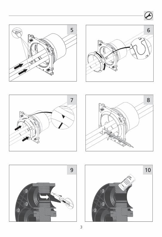
Verschlussdeckel mit dem Gelenkstirnlochschlüssel SLS 6G (Zubehör) über die Schlüsselaufnahmen mit einer Drehbewegung nach links öffnen.
Die Schlüsselaufnahmen im schwarzen Verschlussdeckel falls erforderlich von Betonresten säubern.
Nach der Kabelverlegung den Innenraum der Kabeldurchführung sowie die Kabel mit Kabelreiniger KR60 (Zubehör) von Verschmutzungen reinigen und Dichtfläche auf Beschädigungen prüfen.
Adapterring in die Kabeldurchführung einführen bis dieser bündig am Rahmen der Dichtpackung anliegt.
2
6 Montage (Gebäudeaußenseite)
1
3
5
6
7
8
Kabel dürfen im Dichtbereich keine durchgängigen Längsriefen aufweisen (Kabel evtl. ein Stück vor- oder zurückschieben bis keine Längsriefen mehr sichtbar sind).
Durchmesser der Kabel mit Messschieber ermitteln.
9
Bei Einfachdichtpackungen mit Wandstärke 70 bis 150 mm wird der Blinddeckel (Zweitabdichtung) auf der Anschlussseite (Bajonettaufnahme) mit einem Hammer eingeschlagen und entfernt. Optional kann der Blinddeckel auch rückseitig eingeschlagen werden.Anschließend wird der PE-Deckel auf der Rohrseite entfernt (HSI 150-K70 und -K80 ohne PE-Deckel).
4
Beim Einschlagen des Blinddeckels (Zweitabdichtung) darf die Bajonettaufnahme der Dicht-packung nicht beschädigt werden.
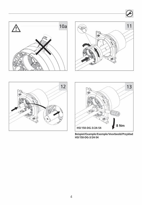
Die Ringraumdichtung über die Kabel klappen und bündig bis zur Außenkante des Adapterringes schieben.
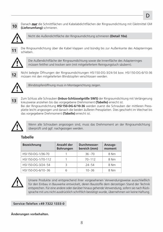
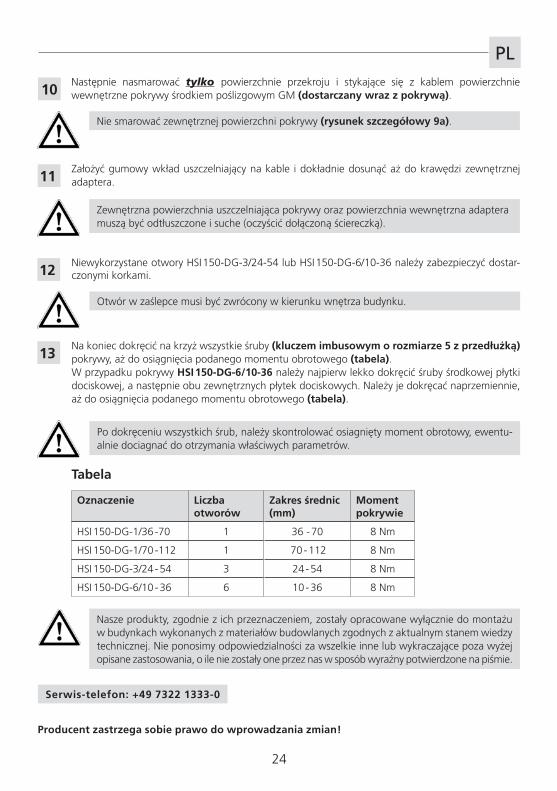
Nicht belegte Öffnungen der Ringraumdichtungen HSI 150-DG-3/24-54 bzw. HSI 150-DG-6/10-36 müssen mit den mitgelieferten Blindstopfen verschlossen werden.
Zum Schluss alle Schrauben (Inbus-Schlüsselgröße SW5) der Ringraumdichtung mit Verlängerung kreuzweise anziehen bis das vorgegebene Drehmoment (Tabelle) erreicht ist.Bei der Ringraumdichtung HSI 150-DG-6/10-36 werden zuerst die Schrauben der mittleren Press-platte leicht angezogen und danach die beiden äußeren Pressplatten. Dies geschieht im Wechsel bis das vorgegebene Drehmoment (Tabelle) erreicht ist.
Wenn alle Schrauben angezogen sind, muss das Drehmoment an der Ringraumdichtung überprüft und ggf. nachgezogen werden.
Bezeichnung Anzahl derBohrungen
Durchmesser-bereich (mm)
Anzugs-moment
HSI 150-DG-1/36-70 1 36 - 70 8 Nm
HSI 150-DG-1/70-112 1 70 - 112 8 Nm
HSI 150-DG-3/24 - 54 3 24 - 54 8 Nm
HSI 150-DG-6/10 - 36 6 10 - 36 8 Nm
Tabelle
11
12
13
Unsere Produkte sind entsprechend ihrer vorgesehenen Verwendungsweise ausschließlich für den Einbau in Bauwerke entwickelt, deren Baustoffe dem derzeitigen Stand der Technik entsprechen. Für eine andere oder darüber hinaus gehende Verwendung, sofern sie nach Rück-sprache mit uns nicht ausdrücklich schriftlich bestätigt wurde, übernehmen wir keine Haftung.
8
DDanach nur die Schnittflächen und Kabelabdichtflächen der Ringraumdichtung mit Gleitmittel GM (Lieferumfang) schmieren.
Nicht die Außendichtfläche der Ringraumdichtung schmieren (Detail 10a).
10
Die Außendichtfläche der Ringraumdichtung sowie die Innenfläche des Adapterringes müssen fettfrei und trocken sein (mit mitgeliefertem Reinigungstuch säubern).
Blindstopfenöffnung muss in Montagerichtung zeigen.
Änderungen vorbehalten.
Service-Telefon +49 7322 1333-0
9
Protect the system cover from damage, moisture and contamination during installation. Check the delivery for completeness and all of the individual parts for any signs of damage. Only un-damaged parts may be installed.
When installing the system cover, the relevant regulations of employer's liability insurance asso-ciations, the VDE [Association for Electrical, Electronic & Information Technologies] requirements, the applicable national safety and accident prevention regulations and the directives (work in-structions and documented procedures) of your company must be observed.
No cleaning agents containing solvents must be used to clean the cable entries! We recommend Hauff-Technik M.T.X.60 cable cleaner.
Press seals are not fixed points or bearings and, as such, cannot sustain mechanical forces. Any anticipated depressions must be compensated for by the installation of centring aids or spacers in the liners or core drillings (HSI 150-DF aluminium flange).
For the connection of pipes or ducts (DN100/DN125) to the HSI 150 system, the upper applica-tion range is restricted as a result of the reduction of the clearance / clear width.
Contents
1 General information and intended use2 Safety instructions3 Description4 Delivery package5 Required tools and equipment6 Installation (exterior side of the building)
1 General and intended use
The HSI 150-DG system cover is suitable for retrofitting and inserting 1 cable with an outer diameter of be-tween 36 and 70 mm, 1 cable with an outer diameter of between 70 and 112 mm, 3 cables with an outer di-ameter of between 24 and 54 mm or respectively 6 cables with an outer diameter of between 10 and 36 mm.
2 Safety instructions
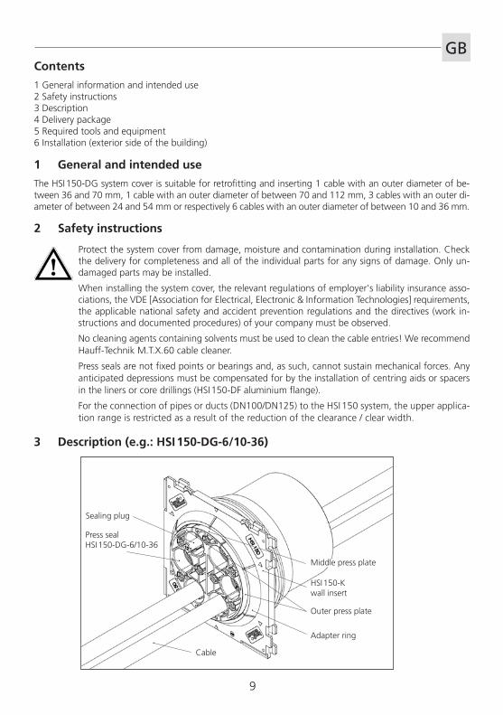
3 Description (e.g.: HSI 150-DG-6/10-36)
Adapter ring
HSI 150-K wall insert
Cable
Press sealHSI 150-DG-6/10-36
Sealing plug
Middle press plate
Outer press plate
GB
10
GB
Optional: 3 HSI 150-PA-3/24-54 press plate covers suitable for HSI 150-DG-3/24-54 or respectively 1 HSI 150-PA-6/10-36 press plate covers suitable for HSI 150-DG-6/10-36
5 Required tools and equipment
For the proper installation of the HRD150-DG press seal, you will require the following tools and equipment besides your standard tools:
Tools:HSI 150-DG installation set consisting of: 1 torque spanner 4-20 Nm, 1/4 inch 1 100 mm extension, 1/4 inch 2 150 mm extensions, 1/4 inch 1 adapter for cordless screwdriver, square, 1/4 inch 1 M6 socket, wrench size 5, 1/4 inch 1 M6 socket, 100 mm long with spherical head, 1/4 inch 1 SLS 6G flexible head spanner (Hauff)
Equipment: 1 KR 60 cable cleaner (Hauff) 1 sliding caliper 1 cleaning cloth 1 cordless screwdriver
4 Delivery package
The delivery package of the HSI 150-DG system cover consists of:
1 HSI 150-DG press seal 1 HSI 150-AR-DG adapter ring 1 GM lubricant pen 1 knife 1 cleaning cloth
1
Key
Work steps
Instructions
(3 sealing plugs suitable for HSI 150-DG-3/24-54 or respectively6 sealing plugs suitable for HSI 150-DG-6/10-36)
GB
11
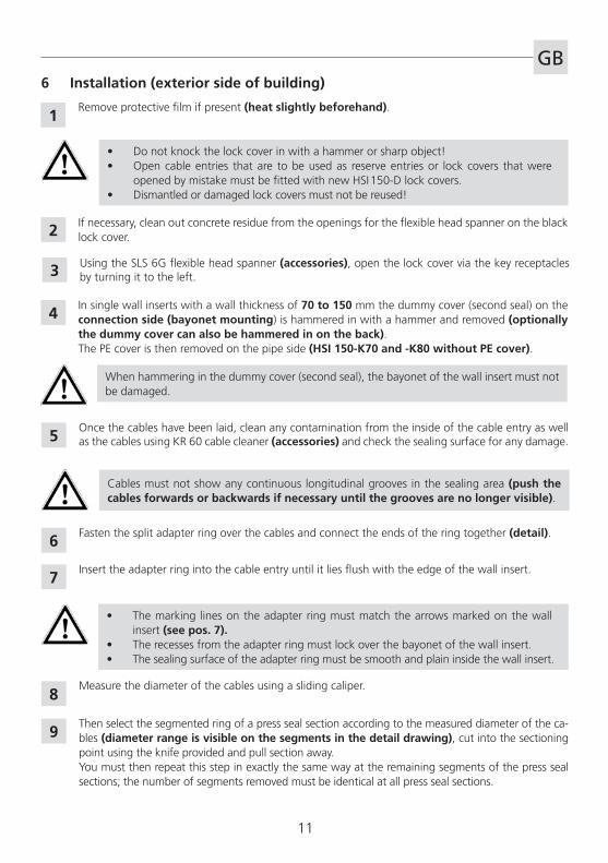
Remove protective film if present (heat slightly beforehand).
• Do not knock the lock cover in with a hammer or sharp object!• Open cable entries that are to be used as reserve entries or lock covers that were
opened by mistake must be fitted with new HSI 150-D lock covers.• Dismantled or damaged lock covers must not be reused!
Fasten the split adapter ring over the cables and connect the ends of the ring together (detail).
• The marking lines on the adapter ring must match the arrows marked on the wall insert (see pos. 7).
• The recesses from the adapter ring must lock over the bayonet of the wall insert.• The sealing surface of the adapter ring must be smooth and plain inside the wall insert.
Then select the segmented ring of a press seal section according to the measured diameter of the ca-bles (diameter range is visible on the segments in the detail drawing), cut into the sectioning point using the knife provided and pull section away.You must then repeat this step in exactly the same way at the remaining segments of the press seal sections; the number of segments removed must be identical at all press seal sections.
Using the SLS 6G flexible head spanner (accessories), open the lock cover via the key receptacles by turning it to the left.
If necessary, clean out concrete residue from the openings for the flexible head spanner on the black lock cover.
Once the cables have been laid, clean any contamination from the inside of the cable entry as well as the cables using KR 60 cable cleaner (accessories) and check the sealing surface for any damage.
Insert the adapter ring into the cable entry until it lies flush with the edge of the wall insert.
2
6 Installation (exterior side of building)
1
3
5
6
7
8
Cables must not show any continuous longitudinal grooves in the sealing area (push the cables forwards or backwards if necessary until the grooves are no longer visible).
Measure the diameter of the cables using a sliding caliper.
9
When hammering in the dummy cover (second seal), the bayonet of the wall insert must not be damaged.
4In single wall inserts with a wall thickness of 70 to 150 mm the dummy cover (second seal) on the connection side (bayonet mounting) is hammered in with a hammer and removed (optionally the dummy cover can also be hammered in on the back). The PE cover is then removed on the pipe side (HSI 150-K70 and -K80 without PE cover).
12
GB
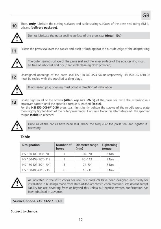
Fasten the press seal over the cables and push it flush against the outside edge of the adapter ring.
Unassigned openings of the press seal HSI 150-DG-3/24-54 or respectively HSI 150-DG-6/10-36 must be sealed with the supplied sealing plugs.
Finally, tighten all of the screws (Allen key size SW 5) of the press seal with the extension in a crossover pattern until the specified torque is reached (table).For the HSI 150-DG-6/10-36 press seal, first slightly tighten the screws of the middle press plate, then slightly tighten both of the outer press plates. Continue to do this alternately until the specified torque (table) is reached.
Once all of the cables have been laid, check the torque at the press seal and tighten if necessary.
Designation Number ofbores
Diameter range (mm)
Tightening torque
HSI 150-DG-1/36-70 1 36 - 70 8 Nm
HSI 150-DG-1/70-112 1 70 - 112 8 Nm
HSI 150-DG-3/24 - 54 3 24 - 54 8 Nm
HSI 150-DG-6/10 - 36 6 10 - 36 8 Nm
Table
11
12
13
Subject to change.
Then, only lubricate the cutting surfaces and cable sealing surfaces of the press seal using GM lu-bricant (delivery package).
Do not lubricate the outer sealing surface of the press seal (detail 10a).
10
The outer sealing surface of the press seal and the inner surface of the adapter ring must be free of lubricant and dry (clean with cleaning cloth provided).
Blind sealing plug opening must point in direction of installation.
As indicated in the instructions for use, our products have been designed exclusively for installation in buildings made from state-of-the-art construction materials. We do not accept liability for use deviating from or beyond this unless our express written confirmation has been obtained in advance.
Service-phone +49 7322 1333-0
13
F
Lors des travaux de montage, protéger le couvercle contre tout endommagement, l'humidité et les saletés. Vérifier contenu de la livraison et que les pi�ces détachées ne soient pas endomma-gées. Seules des pi�ces en bon état doivent �tre montées.
Lors de l'installation du couvercle, il convient de respecter les dispositions régies par les orga-nismes professionnels, les dispositions de la VDE, les prescriptions nationales pour les mati�res de sécurité et de prévention des accidents ainsi que les directives (instructions de travail et de procédure) de votre société.
Pour nettoyer les passe-câbles, ne pas utiliser de produits nettoyants � base de solvants !Nous recommandons le produit nettoyant pour câble Hauff-Technik M.T.X.60.
Les joints annulaires ne sont pas des points fixes ou des supports et, par conséquent, ne peuvent pas absorber les efforts mécaniques. Les affaissements prévisibles doivent �tre compensés par le montage d'aides au centrage et d'entretoises dans les gaines et les carottages (brides aluminium HSI 150-DF).
Lors du raccordement gaines de tirage (DN100/DN125) au syst�me HSI 150, la plage d’utilisation supérieure est restreinte en raison du faible diam�tre ou de la faible largeur de ces gaines.
Sommaire
1 Généralités et usage2 Consignes de sécurité3 Description4 Contenu de la livraison5 Outils et dispositifs d'aide requis6 Montage (extérieur du bâtiment)
1 Généralités et usage
L’anneau d’étanchéité HSI 150-DG est idéal pour des câbles déj� placés et le transit de 1 câble avec un diam�tre extérieur de 36 -70 mm resp. 1 câble d’un diam�tre extérieur de 70 - 112 mm resp.3 câbles avec un diam�tre extérieur de 24 - 54 mm resp. 6 câbles d’un diam�tre extérieur de 10 - 36 mm
2 Consignes de sécurité
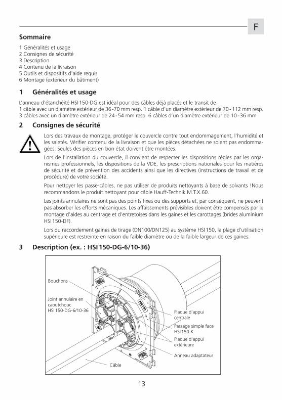
3 Description (ex. : HSI 150-DG-6/10-36)
Anneau adaptateur
Passage simple face HSI 150-K
Câble
Joint annulaire en caoutchoucHSI 150-DG-6/10-36
Bouchons
Plaque d'appui centrale
Plaque d'appui extérieure
14
F
En option : 3 pi�ces d’étanchéité pour des plaques de presse en acier HSI 150-PA-3/24-54 calibré pour HSI 150-DG-3/24-54 1 pi�ce d’étanchéité pour des plaques de presse en acier HSI 150-PA-6/10-36 calibré pour HSI 150-DG-6/10-36
5 Outils et dispositifs d'aide requis
Pour installer correctement le joint annulaire en caoutchouc HRD150-DG, les outils et dispositifs d'aide suivants sont nécessaires en plus des outils standard :
Outils :kit d'assemblage HSI 150-DG se composant de : 1 clé dynamométrique 4 - 20 Nm, � pouce 1 extension de 100 mm, � de pouce 2 extensions de 150 mm, � de pouce 1 adaptateur pour visseuse � accu 100 mm, � pouce 1 embout de tournevis M6 T 5, � pouce 1 embout 100 mm M6 avec t�te arrondie hexagonale � pouce 1 clé � ergots articulée SLS 6G (Hauff)
Dispositifs d'aide : 1 produit nettoyant pour câble KR60 (Hauff) 1 pied � coulisse 1 chiffon 1 visseuse sans fil
4 Contenu de la livraison
Sont fournis dans le contenu de livraison du couvercle HSI 150-DG :
1 joint annulaire en caoutchouc HSI 150-DG 1 anneau adaptateur HSI 150-AR-DG 1 tube de lubrifiant GM 1 couteau 1 chiffon
1
Légende
Étapes de travail
Remarques � respecter
(3 Bouchon pour HSI 150-DG-3/24-546 Bouchon pour HSI 150-DG-6/10-36)
F
15
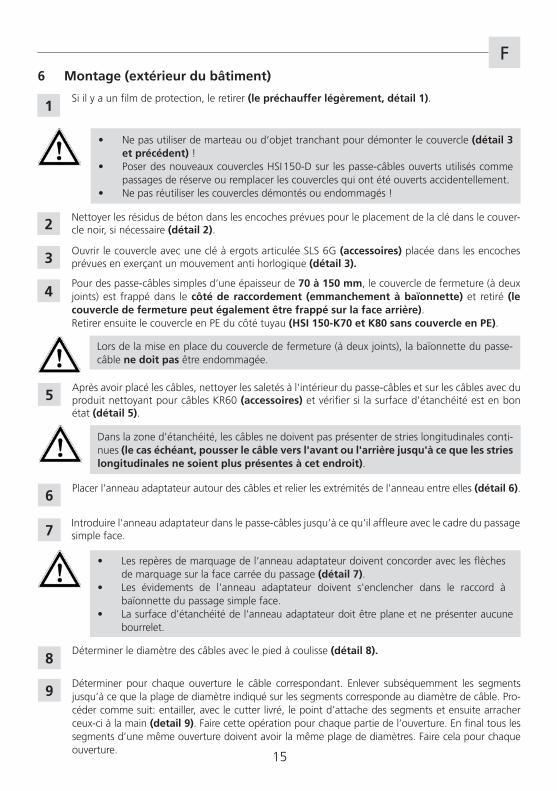
Si il y a un film de protection, le retirer (le préchauffer légèrement, détail 1).
• Ne pas utiliser de marteau ou d‘objet tranchant pour démonter le couvercle (détail 3 et précédent) !
• Poser des nouveaux couvercles HSI 150-D sur les passe-câbles ouverts utilisés comme passages de réserve ou remplacer les couvercles qui ont été ouverts accidentellement.
• Ne pas réutiliser les couvercles démontés ou endommagés !
Placer l'anneau adaptateur autour des câbles et relier les extrémités de l'anneau entre elles (détail 6).
• Les rep�res de marquage de l‘anneau adaptateur doivent concorder avec les fl�ches de marquage sur la face carrée du passage (détail 7).
• Les évidements de l'anneau adaptateur doivent s'enclencher dans le raccord � ba�onnette du passage simple face.
• La surface d'étanchéité de l'anneau adaptateur doit �tre plane et ne présenter aucune bourrelet.
Déterminer pour chaque ouverture le câble correspondant. Enlever subséquemment les segments jusqu’� ce que la plage de diam�tre indiqué sur les segments corresponde au diam�tre de câble. Pro-céder comme suit: entailler, avec le cutter livré, le point d’attache des segments et ensuite arracher ceux-ci � la main (detail 9). Faire cette opération pour chaque partie de l’ouverture. En final tous les segments d’une m�me ouverture doivent avoir la m�me plage de diam�tres. Faire cela pour chaque ouverture.
Ouvrir le couvercle avec une clé � ergots articulée SLS 6G (accessoires) placée dans les encoches prévues en exerçant un mouvement anti horlogique (détail 3).
Nettoyer les résidus de béton dans les encoches prévues pour le placement de la clé dans le couver-cle noir, si nécessaire (détail 2).
Apr�s avoir placé les câbles, nettoyer les saletés � l'intérieur du passe-câbles et sur les câbles avec du produit nettoyant pour câbles KR60 (accessoires) et vérifier si la surface d'étanchéité est en bon état (détail 5).
Introduire l'anneau adaptateur dans le passe-câbles jusqu'� ce qu'il affleure avec le cadre du passage simple face.
2
6 Montage (extérieur du bâtiment)
1
3
5
6
7
8
Dans la zone d'étanchéité, les câbles ne doivent pas présenter de stries longitudinales conti-nues (le cas échéant, pousser le câble vers l'avant ou l'arrière jusqu'à ce que les stries longitudinales ne soient plus présentes à cet endroit).
Déterminer le diam�tre des câbles avec le pied � coulisse (détail 8).
9
Lors de la mise en place du couvercle de fermeture (� deux joints), la ba�onnette du passe-câble ne doit pas �tre endommagée.
4Pour des passe-câbles simples d‘une épaisseur de 70 à 150 mm, le couvercle de fermeture (� deux joints) est frappé dans le côté de raccordement (emmanchement à baïonnette) et retiré (le couvercle de fermeture peut également être frappé sur la face arrière).Retirer ensuite le couvercle en PE du côté tuyau (HSI 150-K70 et K80 sans couvercle en PE).
16
F
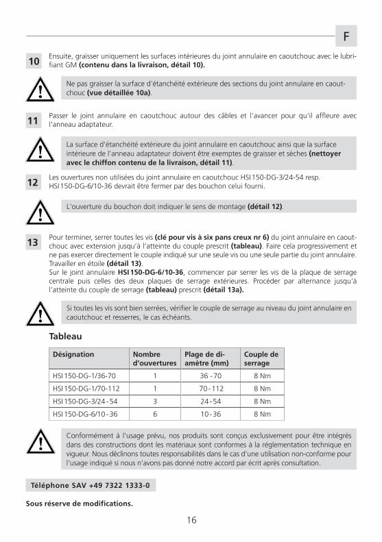
Passer le joint annulaire en caoutchouc autour des câbles et l‘avancer pour qu‘il affleure avec l‘anneau adaptateur.
Les ouvertures non utilisées du joint annulaire en caoutchouc HSI 150-DG-3/24-54 resp. HSI 150-DG-6/10-36 devrait �tre fermer par des bouchon celui fourni.
Pour terminer, serrer toutes les vis (clé pour vis à six pans creux nr 6) du joint annulaire en caout-chouc avec extension jusqu‘� l‘atteinte du couple prescrit (tableau). Faire cela progressivement et ne pas exercer directement le couple indiqué sur une seule vis ou une seule partie du joint annulaire. Travailler en étoile (détail 13).Sur le joint annulaire HSI 150-DG-6/10-36, commencer par serrer les vis de la plaque de serrage centrale puis celles des deux plaques de serrage extérieures. Procéder par alternance jusqu‘� l‘atteinte du couple de serrage (tableau) prescrit (détail 13a).
Si toutes les vis sont bien serrées, vérifier le couple de serrage au niveau du joint annulaire en caoutchouc et resserres, le cas échéants.
Désignation Nombre d’ouvertures
Plage de di-amètre (mm)
Couple de serrage
HSI 150-DG-1/36-70 1 36 - 70 8 Nm
HSI 150-DG-1/70-112 1 70 - 112 8 Nm
HSI 150-DG-3/24 - 54 3 24 - 54 8 Nm
HSI 150-DG-6/10 - 36 6 10 - 36 8 Nm
Tableau
11
12
13
Ensuite, graisser uniquement les surfaces intérieures du joint annulaire en caoutchouc avec le lubri-fiant GM (contenu dans la livraison, détail 10).
Ne pas graisser la surface d'étanchéité extérieure des sections du joint annulaire en caout-chouc (vue détaillée 10a).
10
La surface d'étanchéité extérieure du joint annulaire en caoutchouc ainsi que la surface intérieure de l'anneau adaptateur doivent �tre exemptes de graisser et s�ches (nettoyer avec le chiffon contenu de la livraison, détail 11).
L'ouverture du bouchon doit indiquer le sens de montage (détail 12).
Sous réserve de modifications.
Conformément � l‘usage prévu, nos produits sont conçus exclusivement pour �tre intégrés dans des constructions dont les matériaux sont conformes � la réglementation technique en vigueur. Nous déclinons toutes responsabilités dans le cas d‘une utilisation non-conforme pour l’usage indiqué si nous n‘avons pas donné notre accord par écrit apr�s consultation.
Téléphone SAV +49 7322 1333-0
17
NL
Bescherm het systeemdeksel bij de montage-installatie tegen beschadiging, vocht en verontrei-niging. Controleer de levering op volledigheid, en alle losse onderdelen op eventuele schade. Er mogen alleen onbeschadigde delen worden gemonteerd.
Bij de installatie van het systeemdeksel moeten de geldende voorschriften van de beroeps, de VDE-bepalingen, de geldende nationale veiligheids- en ongevallenpreventievoorschriften en de richtlij-nen (werk- en procedure-instructies) van uw onderneming worden aangehouden.
Voor de reiniging van de kabeldoorvoeren mogen geen reinigingsmiddelen met oplosmiddelen worden gebruik! Wij adviseren Hauff-Technik kabelreiniger M.T.X.60.
Ronde doorvoerdichtingen zijn geen vaste punten of lagers en kunnen dus geen mechanische krachten opnemen. Te verwachten verzakkingen moeten door inbouw van centreerhulpmid-delen resp. afstandshouders in de doorvoerbuizen of kernboringen (aluminium flens HSI 150-DF) worden opgevangen.
Voor deconnectic van kabels en buizen (DN100/DN125) op het systeem HSI 150, wordt als gevolg van de reducering van de inwendige diameter resp. de inwendige breedte, het maximum toepas-singsgebied beperkt.
Inhoud
1 Algemeen en toepassing2 Veiligheidsinstructies3 Beschrijving4 Leverings Inhoud5 Benodigd gereedschap en hulpmiddelen6 Montage (buitenzijde gebouw)
1 Algemeen en toepassing
Het systeemdeksel HSI 150-DG is voor montage naderhand en voor doorvoer van1 Kabel met buitendiameter 36 -70 mm resp. 1 kabel met buitendiameter 70 - 112 mm.3 kabels met buitendiameter 24 -54 mm resp. 6 kabels met buitendiameter 10 - 36 mm geijkt.
2 Veiligheidsinstructies
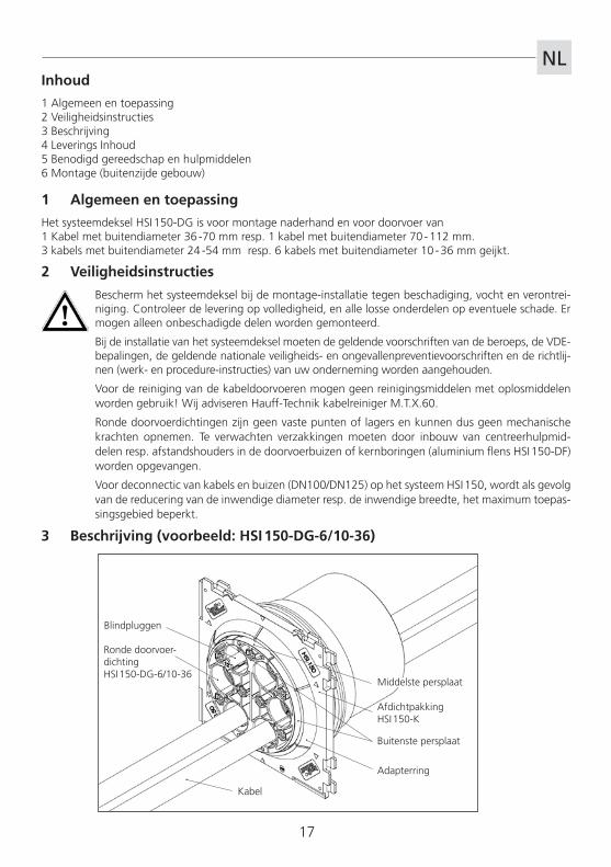
3 Beschrijving (voorbeeld: HSI 150-DG-6/10-36)
Adapterring
Afdichtpakking HSI 150-K
Kabel
Ronde doorvoer-dichtingHSI 150-DG-6/10-36
Blindpluggen
Middelste persplaat
Buitenste persplaat
18
NL
Optie: 3 drukplaat afdichtingen HSI 150-PA-3/24-54 geijkt voor HSI 150-DG-3/24-54 1 drukplaat afdichting HSI 150-PA-6/10-36 geijkt voor HSI 150-DG-6/10-36
5 Benodigd gereedschap en hulpmiddelen
Voor de correcte installatie van de ringkamerafdichting HRD 150-DG heeft u naast het standaard gereed-schap ook de volgende gereedschappen en hulpmiddelen nodig:
Gereedschappen:montageset HSI 150-DG bestaande uit: 1 draaimomentsleutel 4-20 Nm, 1/4” 1 verlenging 100 mm, 1/4” 2 verlengingen 150 mm, 1/4” 1 houder voor akku schroefmachine , vierkant, 1/4“ 1 steeksleutelbit M6, SW 5, 1/4“ 1 steeksleutelbit M6, 100 mm lang met kogelkop, 1/4“ 1 stuk scharnierhaaksleutel SLS 6G (Hauff)
Hulpmiddelen: 1 kabelreiniger KR60 (Hauff) 1 schuifmaat 1 schoonmaakdoek 1 accuschroefmachine
4 Leveringsomvang
Tot de leverings inhoud van het systeemdeksel HSI 150-DG behoren:
1 ronde doorvoerdichting HSI 150-DG 1 adapterring HSI 150-AR-DG 1 glijmiddelstift GM 1 mes 1 schoonmaakdoek
1
Legenda
Arbeidsstappen
aan te houden instructies
(3 blindstoppen geijkt voor HSI 150-DG-3/24-546 blindstoppen geijkt voor HSI 150-DG-6/10-36)
NL
19
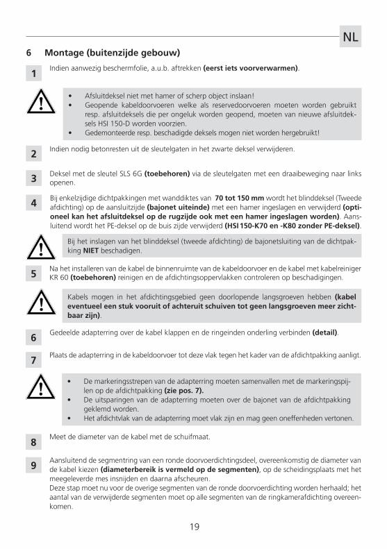
Indien aanwezig beschermfolie, a.u.b. aftrekken (eerst iets voorverwarmen).
• Afsluitdeksel niet met hamer of scherp object inslaan!• Geopende kabeldoorvoeren welke als reservedoorvoeren moeten worden gebruikt
resp. afsluitdeksels die per ongeluk worden geopend, moeten van nieuwe afsluitdek-sels HSI 150-D worden voorzien.
• Gedemonteerde resp. beschadigde deksels mogen niet worden hergebruikt!
Gedeelde adapterring over de kabel klappen en de ringeinden onderling verbinden (detail).
• De markeringsstrepen van de adapterring moeten samenvallen met de markeringspij-len op de afdichtpakking (zie pos. 7).
• De uitsparingen van de adapterring moeten over de bajonet van de afdichtpakking geklemd worden.
• Het afdichtvlak van de adapterring moet vlak zijn en mag geen oneffenheden vertonen.
Aansluitend de segmentring van een ronde doorvoerdichtingsdeel, overeenkomstig de diameter van de kabel kiezen (diameterbereik is vermeld op de segmenten), op de scheidingsplaats met het meegeleverde mes insnijden en daarna afscheuren.Deze stap moet nu voor de overige segmenten van de ronde doorvoerdichting worden herhaald; het aantal van de verwijderde segmenten moet op alle segmenten van de ringkamerafdichting overeen-komen.
Deksel met de sleutel SLS 6G (toebehoren) via de sleutelgaten met een draaibeweging naar links openen.
Indien nodig betonresten uit de sleutelgaten in het zwarte deksel verwijderen.
Na het installeren van de kabel de binnenruimte van de kabeldoorvoer en de kabel met kabelreiniger KR 60 (toebehoren) reinigen en de afdichtingsoppervlakken controleren op beschadigingen.
Plaats de adapterring in de kabeldoorvoer tot deze vlak tegen het kader van de afdichtpakking aanligt.
2
6 Montage (buitenzijde gebouw)
1
3
5
6
7
8
Kabels mogen in het afdichtingsgebied geen doorlopende langsgroeven hebben (kabel eventueel een stuk vooruit of achteruit schuiven tot geen langsgroeven meer zicht-baar zijn).
Meet de diameter van de kabel met de schuifmaat.
9
Bij het inslagen van het blinddeksel (tweede afdichting) de bajonetsluiting van de dichtpak-king NIET beschadigen.
4 Bij enkelzijdige dichtpakkingen met wanddiktes van 70 tot 150 mm wordt het blinddeksel (Tweede afdichting) op de aansluitzijde (bajonet uiteinde) met een hamer ingeslagen en verwijderd (opti-oneel kan het afsluitdeksel op de rugzijde ook met een hamer ingeslagen worden). Aans-luitend wordt het PE-deksel op de buis zijde verwijderd (HSI 150-K70 en -K80 zonder PE-deksel).
20
NL
De ronde doorvoerdichting over de kabel klappen en vlak tot aan de buitenkant van de adapterring schuiven.
Niet gebruikte openingen van de drukring dichting HSI 150-DG-3/24-54 resp. HSI 150-DG-6/10-36 dienen met de meegeleverde blindstoppen afgedicht te worden.
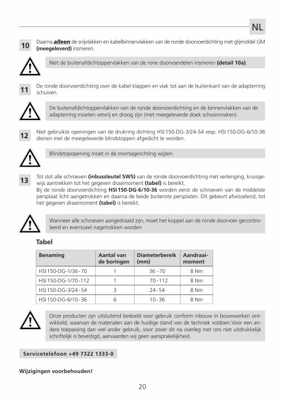
Tot slot alle schroeven (inbussleutel SW5) van de ronde doorvoerdichting met verlenging, kruisge-wijs aantrekken tot het gegeven draaimoment (tabel) is bereikt.Bij de ronde doorvoerdichting HSI 150-DG-6/10-36 worden eerst de schroeven van de middelste persplaat licht aangetrokken en daarna de beide buitenste persplaten. Dit gebeurt afwisselend, tot het gegeven draaimoment (tabel) is bereikt.
Wanneer alle schroeven aangedraaid zijn, moet het koppel aan de ronde doorvoer gecontro-leerd en eventueel nagetrokken worden
Benaming Aantal van de boringen
Diameterbereik (mm)
Aandraai-moment
HSI 150-DG-1/36 - 70 1 36 - 70 8 Nm
HSI 150-DG-1/70 -112 1 70 - 112 8 Nm
HSI 150-DG-3/24 - 54 3 24 - 54 8 Nm
HSI 150-DG-6/10 - 36 6 10 - 36 8 Nm
Tabel
11
12
13
Daarna alleen de snijvlakken en kabelbinnenvlakken van de ronde doorvoerdichting met glijmiddel GM (meegeleverd) insmeren.
Niet de buitenafdichtoppervlakken van de rone doorvoerdelen insmeren (detail 10a).
10
De buitenafdichtoppervlakken van de ronde doorvoerdichting en de binnenvlakken van de adapterring moeten vetvrij en droog zijn (met meegeleverde doek schoonmaken).
Blindstopopening moet in de montagerichting wijzen.
Wijzigingen voorbehouden!
Onze producten zijn uitsluitend bedoeld voor gebruik conform inbouw in bouwwerken ont-wikkeld, waarvan de materialen aan de huidige stand van de techniek voldoen.Voor een an-dere toepassing dan wel ander gebruik, voor zover dit na overleg met ons niet uitdrukkelijk schriftelijk is bevestigd, aanvaarden wij geen aansprakelijkheid.
Servicetelefoon +49 7322 1333-0
21
PL
Podczas montażu pokrywę systemową należy chronić przed uszkodzeniami, wilgocią i zanie-czyszczeniami. Sprawdzić, czy dostawa jest kompletna oraz czy poszczególne części nie są uszko-dzone. Dozwolony jest montaż wyłącznie nieuszkodzonych części.
Podczas montażu pokrywy systemowej należy przestrzegać obowiązujących norm i przepisów.
Do czyszczenia przepustów kablowych nie wolno używać środków czyszczących zawierających rozpuszczalniki! Zalecamy używanie preparatu do czyszczenia kabli Hauff-Technik M.T.X.60.
Gumowe wkłady uszczelniające nie są punktami stałymi ani łożyskami, dlatego też nie są odporne na działanie sił mechanicznych. Należy zapewnić niwelację ewentualnych obniżeń po-przez montaż elementów centrujących lub wsporników w rurach przepustowych lub przewier-tach (kołnierz aluminiowy HSI 150-DF).
W przypadku podłączeń rur ochronnych (DN100/DN125) do systemu HSI 150, wskutek redukcji otworu przelotowego względem przepustu obszar zastosowania zostaje ograniczony.
Spis treści
1 Informacje ogólne i przeznaczenie2 Wskazówki dotyczące bezpieczeństwa3 Opis4 Zakres dostawy5 Niezbędne narzędzia i środki pomocnicze6 Montaż (na zewnątrz budynku od strony wykopu)
1 Informacje ogólne i przeznaczenie produktu
Pokrywa systemowa HSI 150-DG jest przeznaczona do wprowadzenia i uszczelnienia (także pomontażowego): 1 kabla o średnicy od 36 do 70 mm lub 1 kabla o średnicy od 70 do 112 mm, lub 3 kabli o średnicy od 24 do 54 mm, lub 6 kabli o średnicy od 10 do 36 mm.
2 Wskazówki dotyczące bezpieczeństwa
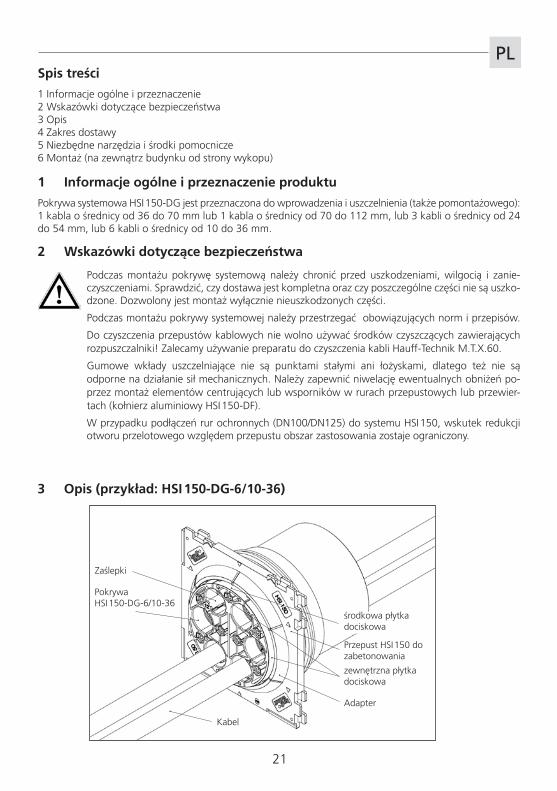
3 Opis (przykład: HSI 150-DG-6/10-36)
Adapter
Przepust HSI 150 do zabetonowania
Kabel
PokrywaHSI 150-DG-6/10-36
Zaślepki
środkowa płytka dociskowa
zewnętrzna płytka dociskowa
22
PL
Opcja: 3 sztuki osłony płytek dociskowych HSI 150-PA-3/24-54 do HSI150-DG-3/24-54 lub 1 sztuka osłony płytek dociskowych HSI 150-PA-6/10-36 do HSI150-DG-6/10-36
5 Niezbędne narzędzia i środki pomocnicze
Do prawidłowego montażu gumowego wkładu uszczelniającego HRD150-DG potrzebne są, oprócz standar-dowych narzędzi, następujące narzędzia i środki pomocnicze:
Narzędzia:zestaw montażowy HSI 150-DG, składający się z: 1 Zestaw montażowy HSI 150-DG, w którego skład wchodzą: 1 klucz dynamometryczny 4-20 Nm, 1/4 cala 1 przedłużka 100 mm, 1/4 cala 2 przedłużki po 150 mm, 1/4 cala 1 uchwyt czworokątny do wkrętarki akumulatorowej, 1/4 cala 1 nasadka do klucza nasadowego M6, rozm. 5, 1/4 cala 1 nasadka do klucza nasadowego M6, długość 100 mm, z końcówką kulową, 1/4 cala 1 klucza SLS 6G (Hauff)
Środki pomocnicze 1 preparat do czyszczenia kabli KR60 (Hauff) 1 suwmiarka 1 ściereczka 1 wkrętak akumulatorowy
4 Zakres dostawy
Zakres dostawy pokrywy systemowej HSI 150-DG obejmuje:
1 pokrywa HSI 150-DG 1 Adapter HSI 150-AR-DG 1 środek poślizgowy w sztyfcie GM 1 nóż 1 ściereczka
1
Legenda
Czynności
Ważne wskazówki
(3 zaślepek do otworów w HSI 150-DG-3/24-54 lub6 zaślepek do otworów w HSI 150-DG-6/10-36)

PL
23
Jeżeli na przepuście kablowym HSI 150 jest założona folia ochronna, należy ją lekko ogrzać i ściągnąć.
• Nie rozbijać pokrywy zamykającej młotkiem ani innym przedmiotem o ostrych krawędziach!
• Otwarte przepusty kablowe przeznaczone do wykorzystania jako przepusty zapasowe lub przepusty, z których przypadkowo zdjęto pokrywę zamykającą, należy wyposażyć w nowe pokrywy zamykające HSI 150-D!
• Zdemontowanych lub uszkodzonych pokryw zamykających nie należy ponownie wykorzystywać!
Założyć adapter z rozłączonymi końcami na kable i połączyć końce pierścienia (rysunek szczegółowy).
• Kreski na adapterze muszą zbiegać się ze strzałkami na przepuście kablowym HSI 150 (zobacz poz. 6).
• Wycięcia w adapterze muszą zaskoczyć na złącza mocujące wewnątrz przepustu kablowego HSI 150.
• Powierzchnia uszczelniająca adaptera musi być równa i nie może posiadać żadnych pofałdowań.
Następnie wybrać pierścienie segmentowe pokrywy stosownie do ustalonej średnicy kabli (zakres średnic jest widoczny na segmentach na rysunku szczegółowym), naciąć dołączonym nożem w miejscu przedzielenia i oderwać.Krok ten należy powtórzyć w ten sam sposób na pozostałych segmentach pokrywy; liczba usuniętych segmentów musi być identyczna we wszystkich częściach pokrywy.
Chwytając kluczem SLS 6G (akcesoria) za otwór pod klucz, otworzyć pokrywę zamykającą ruchem obrotowym w lewo.
W razie potrzeby oczyścić otwór pod klucz w czarnej pokrywie zamykającej z resztek betonu.
Po wciągnięciu kabli oczyścić wewnętrzną część przepustu kablowego oraz kable preparatem do czy-szczenia kabli KR60 (akcesoria) i skontrolować powierzchnię uszczelniającą pod kątem uszkodzeń.
Wprowadzić adapter do przepustu kablowego, aż znajdzie się w jednej linii z znacznikami na froncie przepustu kablowego HSI 150.
2
6 Montaż (na zewnątrz budynku od strony wykopu)
1
3
5
6
7
8
W obszarze uszczelnienia kable nie mogą posiadać ciągłych rowków wzdłużnych (ewen-tualnie nieco przesunąć kable do przodu lub do tyłu, aż rowki wzdłużne nie będą widoczne).
Zmierzyć średnice kabli za pomocą suwmiarki.
9
Podczas wbijania pokrywy zamykającej (dodatkowe uszczelnienie) nie można dopuścić do uszkodzenia przepustu kablowego.
4W przypadku jednostronnych przepustów kablowych w ścianach o grubości od 70 do 150 mm pokry-wa zamykająca (dodatkowe uszczelnienie) po stronie przyłącza (mocowanie bagnetowe) jest wbi-jana i usuwana za pomocą młotka (ew. pokrywę zamykającą można wbić od strony tylnej).Następnie należy usunąć pokrywę PE po stronie rury (HSI 150-K70 i -K80 bez pokrywy PE).
24
PL
Założyć gumowy wkład uszczelniający na kable i dokładnie dosunąć aż do krawędzi zewnętrznej adaptera.
Niewykorzystane otwory HSI 150-DG-3/24-54 lub HSI 150-DG-6/10-36 należy zabezpieczyć dostar-czonymi korkami.
Na koniec dokręcić na krzyż wszystkie śruby (kluczem imbusowym o rozmiarze 5 z przedłużką) pokrywy, aż do osiągnięcia podanego momentu obrotowego (tabela).W przypadku pokrywy HSI 150-DG-6/10-36 należy najpierw lekko dokręcić śruby środkowej płytki dociskowej, a następnie obu zewnętrznych płytek dociskowych. Należy je dokręcać naprzemiennie, aż do osiągnięcia podanego momentu obrotowego (tabela).
Po dokręceniu wszystkich śrub, należy skontrolować osiagnięty moment obrotowy, ewentu-alnie dociagnać do otrzymania właściwych parametrów.
Oznaczenie Liczbaotworów
Zakres średnic (mm)
Moment pokrywie
HSI 150-DG-1/36 -70 1 36 - 70 8 Nm
HSI 150-DG-1/70 -112 1 70 - 112 8 Nm
HSI 150-DG-3/24 - 54 3 24 - 54 8 Nm
HSI 150-DG-6/10 - 36 6 10 - 36 8 Nm
Tabela
11
12
13
Następnie nasmarować tylko powierzchnie przekroju i stykające się z kablem powierzchnie wewnętrzne pokrywy środkiem poślizgowym GM (dostarczany wraz z pokrywą).
Nie smarować zewnętrznej powierzchni pokrywy (rysunek szczegółowy 9a).
10
Zewnętrzna powierzchnia uszczelniająca pokrywy oraz powierzchnia wewnętrzna adaptera muszą być odtłuszczone i suche (oczyścić dołączoną ściereczką).
Otwór w zaślepce musi być zwrócony w kierunku wnętrza budynku.
Producent zastrzega sobie prawo do wprowadzania zmian!
Nasze produkty, zgodnie z ich przeznaczeniem, zostały opracowane wyłącznie do montażu w budynkach wykonanych z materiałów budowlanych zgodnych z aktualnym stanem wiedzy technicznej. Nie ponosimy odpowiedzialności za wszelkie inne lub wykraczające poza wyżej opisane zastosowania, o ile nie zostały one przez nas w sposób wyraźny potwierdzone na piśmie.
Serwis-telefon: +49 7322 1333-0

25
Notizen / Notes / Remarques / Opmerkingen / Notatki

Wir
wei
sen
ausd
rück
lich
dara
uf h
in, d
ass
bei A
bwei
chun
g vo
n de
n A
ngab
en in
der
Mon
tage
anle
itung
und
bei
uns
achg
emäß
er V
erw
endu
ng u
nser
er P
rodu
kte
sow
ie d
eren
Kom
bina
tion
mit
Frem
dpro
dukt
en f
ür e
vent
uell
auft
rete
nde
Folg
esch
äden
kei
nerle
i G
ewäh
rleis
tung
übe
rnom
men
wird
.
Hauff-Technik GmbH & Co. KGRobert-Bosch-Straße 989568 Hermaringen, GERMANY
Tel. +49 7322 1333-0Fax +49 7322 1333-999
a_hs
i150
_dg_
1501
2750
9003
2033
![Dekpol Steel...8 9 DEKPOL STEEL DEKPOL STEEL PRODUKTCODE Schnittbreite [mm] Inhalt SAE [L] Zähne DG-D0-250mm DG-D0-300mm DG-D0-400mm 250 300 400 2 3 3 500 4 …](https://img.pdfslide.org/doc/110x75/60bb36bc99abeb068040242a/dekpol-steel-8-9-dekpol-steel-dekpol-steel-produktcode-schnittbreite-mm-inhalt.jpg)