Embed Size (px)
Citation preview
Power Cable Catalogue «Suhner & Co.»with Gottlieb Suhner (1900)
SMACHINEcomponents
K
K00_QX6.qxp:K00 21.8.2008 14:30 Uhr Seite 3
SMACHINEcomponents
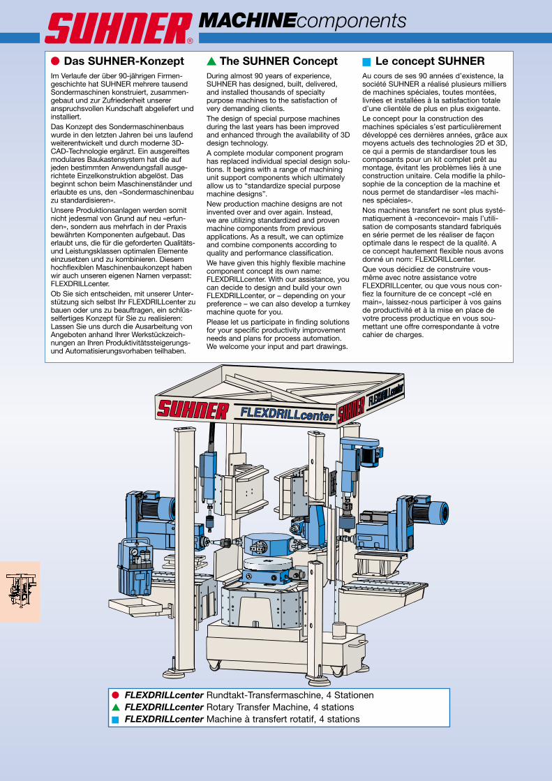
● Das SUHNER-KonzeptIm Verlaufe der über 90-jährigen Firmen-geschichte hat SUHNER mehrere tausendSondermaschinen konstruiert, zusammen-gebaut und zur Zufriedenheit unsereranspruchsvollen Kundschaft abgeliefert undinstalliert.Das Konzept des Sondermaschinenbauswurde in den letzten Jahren bei uns laufendweiterentwickelt und durch moderne 3D-CAD-Technologie ergänzt. Ein ausgereiftesmodulares Baukastensystem hat die aufjeden bestimmten Anwendungsfall ausge-richtete Einzelkonstruktion abgelöst. Dasbeginnt schon beim Maschinenständer underlaubte es uns, den «Sondermaschinenbauzu standardisieren».Unsere Produktionsanlagen werden somitnicht jedesmal von Grund auf neu «erfun-den», sondern aus mehrfach in der Praxisbewährten Komponenten aufgebaut. Daserlaubt uns, die für die geforderten Qualitäts-und Leistungsklassen optimalen Elementeeinzusetzen und zu kombinieren. Diesemhochflexiblen Maschinenbaukonzept habenwir auch unseren eigenen Namen verpasst:FLEXDRILLcenter.Ob Sie sich entscheiden, mit unserer Unter-stützung sich selbst Ihr FLEXDRILLcenter zubauen oder uns zu beauftragen, ein schlüs-selfertiges Konzept für Sie zu realisieren:Lassen Sie uns durch die Ausarbeitung vonAngeboten anhand Ihrer Werkstückzeich-nungen an Ihren Produktivitätssteigerungs-und Automatisierungsvorhaben teilhaben.
▲ The SUHNER ConceptDuring almost 90 years of experience,SUHNER has designed, built, delivered,and installed thousands of specialtypurpose machines to the satisfaction ofvery demanding clients.The design of special purpose machinesduring the last years has been improvedand enhanced through the availability of 3Ddesign technology.A complete modular component programhas replaced individual special design solu-tions. It begins with a range of machiningunit support components which ultimatelyallow us to “standardize special purposemachine designs”.New production machine designs are notinvented over and over again. Instead,we are utilizing standardized and provenmachine components from previousapplications. As a result, we can optimizeand combine components according toquality and performance classification.We have given this highly flexible machinecomponent concept its own name:FLEXDRILLcenter. With our assistance, youcan decide to design and build your ownFLEXDRILLcenter, or – depending on yourpreference – we can also develop a turnkeymachine quote for you.Please let us participate in finding solutionsfor your specific productivity improvementneeds and plans for process automation.We welcome your input and part drawings.
■ Le concept SUHNERAu cours de ses 90 années d’existence, lasociété SUHNER a réalisé plusieurs milliersde machines spéciales, toutes montées,livrées et installées à la satisfaction totaled’une clientèle de plus en plus exigeante.Le concept pour la construction desmachines spéciales s’est particulièrementdéveloppé ces dernières années, grâce auxmoyens actuels des technologies 2D et 3D,ce qui a permis de standardiser tous lescomposants pour un kit complet prêt aumontage, évitant les problèmes liés à uneconstruction unitaire. Cela modifie la philo-sophie de la conception de la machine etnous permet de standardiser «les machi-nes spéciales».Nos machines transfert ne sont plus systé-matiquement à «reconcevoir» mais l’utili-sation de composants standard fabriquésen série permet de les réaliser de façonoptimale dans le respect de la qualité. Ace concept hautement flexible nous avonsdonné un nom: FLEXDRILLcenter.Que vous décidiez de construire vous-même avec notre assistance votreFLEXDRILLcenter, ou que vous nous con-fiez la fourniture de ce concept «clé enmain», laissez-nous participer à vos gainsde productivité et à la mise en place devotre process productique en vous sou-mettant une offre correspondante à votrecahier de charges.
● FLEXDRILLcenter Rundtakt-Transfermaschine, 4 Stationen▲ FLEXDRILLcenter Rotary Transfer Machine, 4 stations■ FLEXDRILLcenter Machine à transfert rotatif, 4 stations
K01_Einleitung_QX6.qxp:K01_Einleitung 21.8.2008 14:31 Uhr Seite 10
●FL
EX
DR
ILLc
ente
rR
und
takt
-Tra
nsfe
rmas
chin
e,6
Sta
tione
n,ko
mp
lett
imK
atal
og
▲FL
EX
DR
ILLc
ente
rR
otar
ytr
ansf
erm
achi
ne,
6st
atio
ns,
com
ple
tely
inca
talo
gue
■FL
EX
DR
ILLc
ente
rM
achi
neà
tran
sfer
tro
tatif
,6
stat
ions
,co
mp
let
dan
sle
cata
log
ue
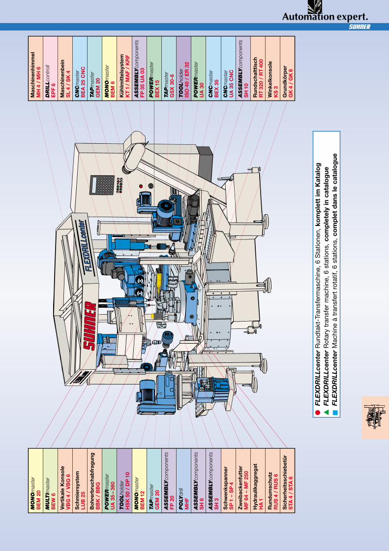
MO
NO
mas
ter
BE
M20
MU
LTIm
aste
rB
EW
6
Vert
ikal
eK
ons
ole
VB
G4
/V
BG
6
Sch
mie
rsys
tem
LUB
25
Bo
hrer
bru
chab
frag
ung
BB
K/
BB
G
PO
WE
Rm
aste
rU
A35
–36
0
TO
OL
hold
erH
SK
50/
DP
10
MO
NO
mas
ter
BE
M12
TAP
mas
ter
GE
M20
ASSE
MB
LYco
mpo
nent
sFP
20
PO
LYdr
illM
HF
ASSE
MB
LYco
mpo
nent
sS
H6
ASSE
MB
LYco
mpo
nent
sS
H3
Sch
wen
ksp
anne
rS
P1
–S
P4
Zw
eib
acke
nfut
ter
MF
64–
MF
250
Hyd
raul
ikag
gre
gat
HA
1
Run
dum
schu
tzR
US
4/
RU
S6
Sic
herh
eits
schi
ebet
ürS
TA4
/S
TA6
Mas
chin
enhi
mm
elM
H4
/M
H6
DR
ILL
cont
roll
EP
F6
Mas
chin
enb
ein
SL
4/
SK
4
CN
Cm
aste
rB
EA
25C
NC
TAP
mas
ter
GE
M20
MO
NO
mas
ter
BE
M6
Küh
lmit
tels
yste
mK
T1
/M
AF
/K
RF
ASSE
MB
LYco
mpo
nent
sFP
35U
A03
PO
WE
Rm
aste
rB
EX
15
TAP
mas
ter
GS
X30
-6
TO
OL
hold
erIS
O40
/E
R32
PO
WE
Rm
aste
rU
A30
CN
Cm
aste
rB
EX
35
CN
Cm
aste
rU
A35
CN
C
ASSE
MB
LYco
mpo
nent
sS
H10
Run
dsc
halt
tisc
hR
T32
0/
RT
400
Win
kelk
ons
ole
KS
3
Gru
ndkö
rper
GK
4/
GK
6
K01_Einleitung_QX6.qxp:K01_Einleitung 21.8.2008 14:31 Uhr Seite 11
S
K10
MACHINEcomponents
∅ 70
10H7×3,5
∅ 100 H8/5
322
360
140
170
6×M12
2× ∅16H7
110
110
170
465
110
M 16 (4×)
680400
60
12 H7 (2×)
10 H7 (1×)
1300
440
60
160
400
M16 (4× )
10 H7
12 H7 (2× )
1200
600
10 H7
340
6014
017
028
0
M12 (6× )
16 H7 (2× )
300
70
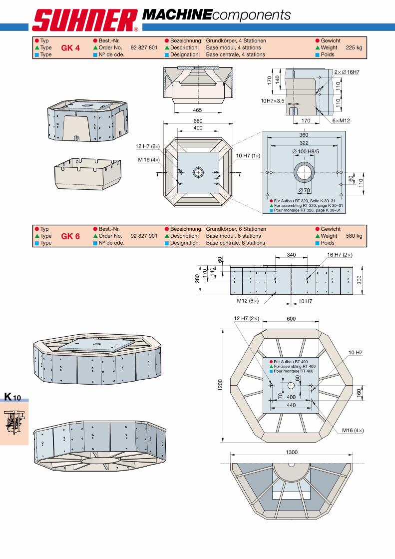
● Typ ● Best.-Nr. ● Bezeichnung: Grundkörper, 4 Stationen ● Gewicht▲Type GK 4 ▲Order No. 92 827 801 ▲Description: Base modul, 4 stations ▲Weight 225 kg■ Type ■ No de cde. ■ Désignation: Base centrale, 4 stations ■ Poids
● Typ ● Best.-Nr. ● Bezeichnung: Grundkörper, 6 Stationen ● Gewicht▲Type GK 6 ▲Order No. 92 827 901 ▲Description: Base modul, 6 stations ▲Weight 580 kg■ Type ■ No de cde. ■ Désignation: Base centrale, 6 stations ■ Poids
● Für Aufbau RT 320, Seite K 30–31▲ For assembling RT 320, page K 30–31■ Pour montage RT 320, page K 30–31
● Für Aufbau RT 400▲ For assembling RT 400■ Pour montage RT 400
K10_K15_QX6.qxp:K10_K15 21.8.2008 14:32 Uhr Seite 10
780
70 140
80150
K11
2080
140 70
100
100 38
0
110
990
580
150
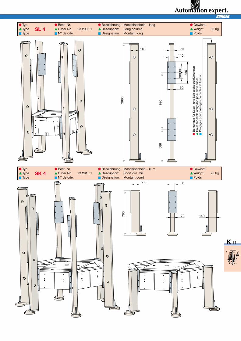
● Typ ● Best.-Nr. ● Bezeichnung: Maschinenbein – lang ● Gewicht▲Type SL 4 ▲Order No. 93 290 01 ▲Description: Long column ▲Weight 50 kg■ Type ■ No de cde. ■ Désignation: Montant long ■ Poids
● Typ ● Best.-Nr. ● Bezeichnung: Maschinenbein – kurz ● Gewicht▲Type SK 4 ▲Order No. 93 291 01 ▲Description: Short column ▲Weight 25 kg■ Type ■ No de cde. ■ Désignation: Montant court ■ Poids
●B
ohru
ngen
für
Kab
el-
und
Sch
lauc
hdur
chfü
hrun
gen
▲H
oles
for
cab
leen
try
and
pne
umat
ictu
bes
■P
erça
ges
pou
rp
assa
ges
de
cab
les
ettu
yaux
K10_K15_QX6.qxp:K10_K15 21.8.2008 14:32 Uhr Seite 11
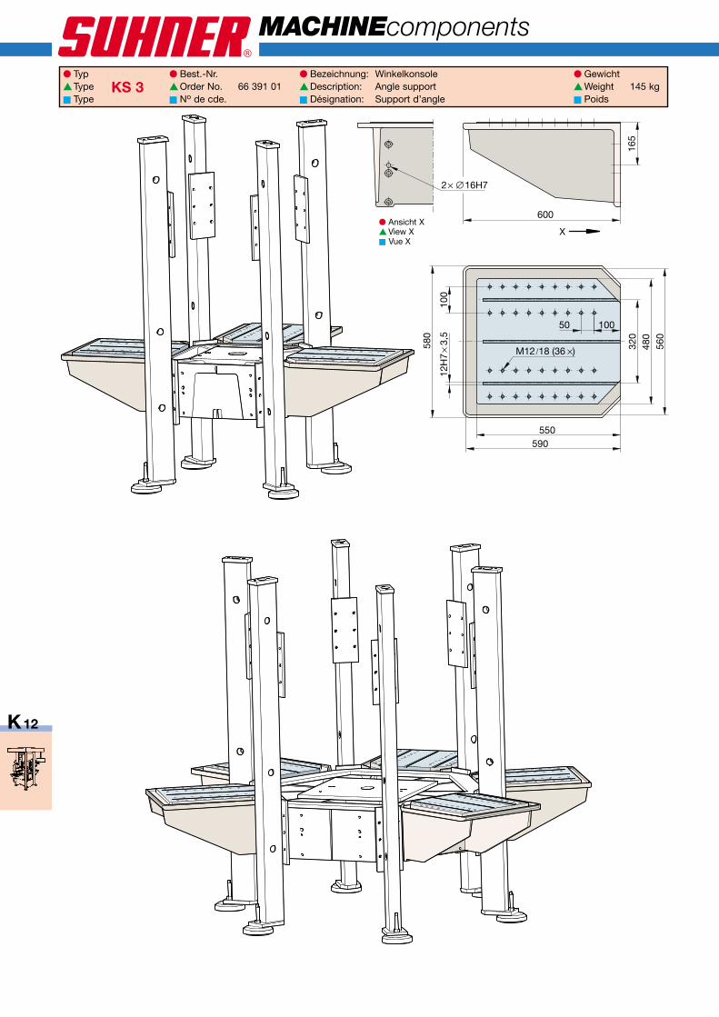
10050
100
320
12H
7×
3,5
M12 /18 (36 ×)
165
2× ∅16H7
480
560
580
550590
600
X
S
K12
MACHINEcomponents
● Typ ● Best.-Nr. ● Bezeichnung: Winkelkonsole ● Gewicht▲Type KS 3 ▲Order No. 66 391 01 ▲Description: Angle support ▲Weight 145 kg■ Type ■ No de cde. ■ Désignation: Support d’angle ■ Poids
● Ansicht X▲ View X■ Vue X
K10_K15_QX6.qxp:K10_K15 21.8.2008 14:32 Uhr Seite 12
K13
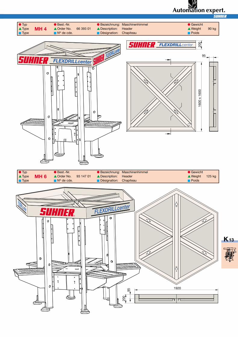
1920
200
95
1600
x16
0020
0
95
FLEXDRILLcenter
● Typ ● Best.-Nr. ● Bezeichnung: Maschinenhimmel ● Gewicht▲Type MH 4 ▲Order No. 66 393 01 ▲Description: Header ▲Weight 90 kg■ Type ■ No de cde. ■ Désignation: Chapiteau ■ Poids
● Typ ● Best.-Nr. ● Bezeichnung: Maschinenhimmel ● Gewicht▲Type MH 6 ▲Order No. 93 147 01 ▲Description: Header ▲Weight 125 kg■ Type ■ No de cde. ■ Désignation: Chapiteau ■ Poids
K10_K15_QX6.qxp:K10_K15 21.8.2008 14:32 Uhr Seite 13
S
K14
MACHINEcomponents
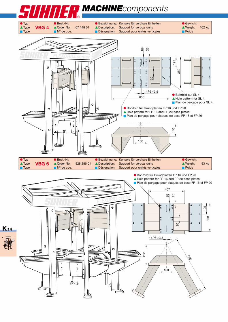
650
160
140
30
14P6 × 3,5
55 25
350
125
30
14P6 × 3,5
55 25
230
150
650
407
125
320
● Typ ● Best.-Nr. ● Bezeichnung: Konsole für vertikale Einheiten ● Gewicht▲Type VBG 4 ▲Order No. 67 148 01 ▲Description: Support for vertical units ▲Weight 102 kg■ Type ■ No de cde. ■ Désignation: Support pour unités verticales ■ Poids
● Typ ● Best.-Nr. ● Bezeichnung: Konsole für vertikale Einheiten ● Gewicht▲Type VBG 6 ▲Order No. 928 286 01 ▲Description: Support for vertical units ▲Weight 93 kg■ Type ■ No de cde. ■ Désignation: Support pour unités verticales ■ Poids
● Bohrbild für Grundplatten FP 16 und FP 20▲Hole pattern for FP 16 and FP 20 base plates■ Plan de perçage pour plaques de base FP 16 et FP 20
● Bohrbild für Grundplatten FP 16 und FP 20▲Hole pattern for FP 16 and FP 20 base plates■ Plan de perçage pour plaques de base FP 16 et FP 20
● Bohrbild auf SL 4▲Hole pattern for SL 4■ Plan de perçage pour SL 4
K10_K15_QX6.qxp:K10_K15 21.8.2008 14:32 Uhr Seite 14
K15
H
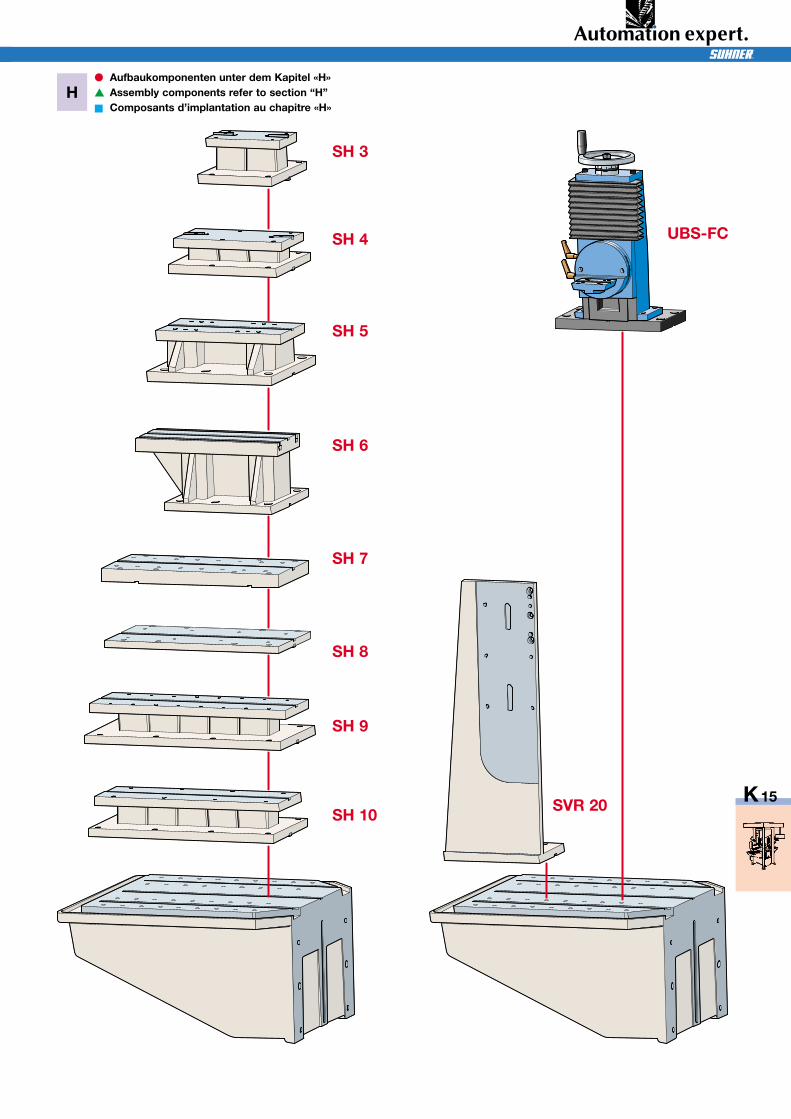
SH 3
SH 4
SH 5
SH 6
SH 7
SH 8
SH 9
SH 10SVR 20
UBS-FC
● Aufbaukomponenten unter dem Kapitel «H»▲ Assembly components refer to section “H”■ Composants d’implantation au chapitre «H»
K10_K15_QX6.qxp:K10_K15 21.8.2008 14:32 Uhr Seite 15
∅ 320 / ∅ 500
4 – 6 – 8
N: 30000Nm: 5000
RT 320/RT 400
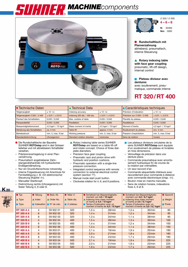
RT 320 A 4 4 59 932 01 320 1,5 s 28/min 1,3 s 30/min 85RT 320 A 6 6 59 932 02 320 1,4 s 31/min 1,2 s 34/min 85RT 320 A 8 8 59 932 03 320 1,3 s 34/min 1,1 s 38/min 85RT 320 B 4 4 59 932 04 400 1,5 s 28/min 1,3 s 30/min 100RT 320 B 6 6 59 932 05 400 1,4 s 31/min 1,2 s 34/min 100RT 320 B 8 8 59 932 06 400 1,3 s 34/min 1,1 s 38/min 100RT 400 A 4 4 59 933 01 400 2,1 s 19/min 1,9 s 20/min 180RT 400 A 6 6 59 933 02 400 2,0 s 21/min 1,8 s 23/min 180RT 400 A 8 8 59 933 03 400 1,9 s 24/min 1,7 s 26/min 180RT 400 B 4 4 59 933 04 500 2,1 s 19/min 1,9 s 20/min 225RT 400 B 6 6 59 933 05 500 2,0 s 21/min 1,8 s 23/min 225RT 400 B 8 8 59 933 06 500 1,9 s 24/min 1,7 s 26/min 225
S
K20
MACHINEcomponents
● Typ ● Teilung ● Best.-Nr. ● Teller ∅ ● Schaltzeit bei Massenträgheits- ● Schaltzeit bei Massenträgheits- ● Gewichtmoment von 4,5 / 10 kgm2 moment von 3,0 / 6,7 kgm2
▲ Type ▲ Index ▲ Order No. ▲ Table dia. ▲ Indexing time mass moment ▲ Indexing time mass moment ▲ Weightof inertia at 4.5 / 10 kgm2 of inertia at 3.0 / 6.7 kgm2
■ Type ■ Indexation ■ N° de cde. ■ ∅ plateau ■ Temps d’indexation avec un ■ Temps d’indexation avec un ■ Poidsmoment d’inertie de 4,5 / 10 kgm2 moment d’inertie de 3,0 / 6,7 kgm2
● Technische DatenTeilgenauigkeit ± 12 ?s
Teilgenauigkeit ∅ 320 / ∅ 400 ± 0,01 / ± 0,012
Planlauf des Schalttellers 0,035 / 0,040
Planparallelität 0,045 / 0,050
Massenträgheitsmoment 4,5 kgm2 / 10 kgm2
Abhebung des Schalttellers ca. 4 mm
Betriebsdruck min. 5, max. 8 bar
Standarddrehrichtung Uhrzeigersinn
▲ Technical DataIndexing accuracy ± 12 ?s
Indexing 320 dia. / 400 dia. ± 0.01 / ± 0.012
Max. wobble of table 0.035 / 0.040
Parallelism 0.045 / 0.050
Mass moment of inertia 4.5 kgm2 / 10 kgm2
Table lift approx. 4 mm
Working pressure min. 5, max. 8 bar
Standard rotation direction clockwise
■ Caractéristiques techniquesPrécision d’indexation ± 12 ?s
Précision sur ∅ 320 / ∅ 400 ± 0,01 / ± 0,012
Planéité du plateau 0,035 / 0,040
Parallélisme 0,045 / 0,050
Moment d’inertie 4,5 kgm2 / 10 kgm2
Soulèvement du plateau env. 4 mm
Pression d’exploitation min. 5, max. 8 bar
Sens de rotation horaire
● Rundschalttisch mitPlanverzahnungabhebend, pneumatisch,interne Steuerung
▲ Rotary indexing tablewith face gear couplingpneumatic, lift-off design,internal control
■ Plateau diviseur avecdenturesavec soulèvement, pneu-matique, commande interne
● Die Rundschalttische der BaureiheSUHNER ROTOstep sind in drei Grössenlieferbar und mit abhebbarem Schalttellerversehen.
– Präzisionsverriegelung in einer Plan-verzahnung.
– Pneumatisch angetriebener Zahn-stangendrehantrieb mit hydraulischerEndlagendämpfung.
– Nur ein Druckluftanschluss notwendig.– Interne Folgesteuerung mit Anschluss für
Fernbetätigung z. B. mit elektronischerSteuerung (Kapitel «I»).
– Manueller Startknopf.– Drehrichtung rechts (Uhrzeigersinn) mit
fester Teilung 4, 6 oder 8.
▲ Rotary indexing table series SUHNERROTOstep are based on a table lift-offand rotate concept. Choice of three dial-plate diameters.
– Precision face gear coupling.– Pneumatic rack and pinion drive with
hydraulic and position cushions.– Pneumatic operation with a single-line
pressure connection.– Integrated control sequence with remote
connection to external electrical controlsystem (section “I”).
– Manual mode start push button.– Clockwise rotation for 4, 6, and 8 positions.
■ Les plateaux diviseurs circulaires de lasérie SUHNER ROTOstep sont équipésd’un soulèvement de plateau et livrablesen trois dimensions.
– Verrouillage de précision dans unedenture plane.
– Commande pneumatique avec amortis-sement hydraulique fin de course dela rotation par crémaillère.
– Un seul raccord d’air.– Commande séquentielle intérieure avec
raccordement pour commande à distanceavec commande électronique (chap. «I»).
– Bouton mise en marche manuelle.– Sens de rotation horaire, indexations
fixes 4, 6 et 8.
K20_K21_QX6.qxp:K60_K61 21.8.2008 14:33 Uhr Seite 20
∅ 40 H8
∅ 320 – RT 320 A
∅ 400 – RT 320 B
∅ 50 H8∅ 400 – RT 400 A
∅ 500 – RT 400 B
496285
∅ 35
632363
∅ 30
400360331
110 110
460440401
120 120
2550
160
3,5
320
48
25
58
40
∅80
∅80
400
∅95
78
4×1
8
3560
205
4,0
110
∅95
105
4×1
8
160
1
2
3
4
5
6
7
8
4
2
40
K21
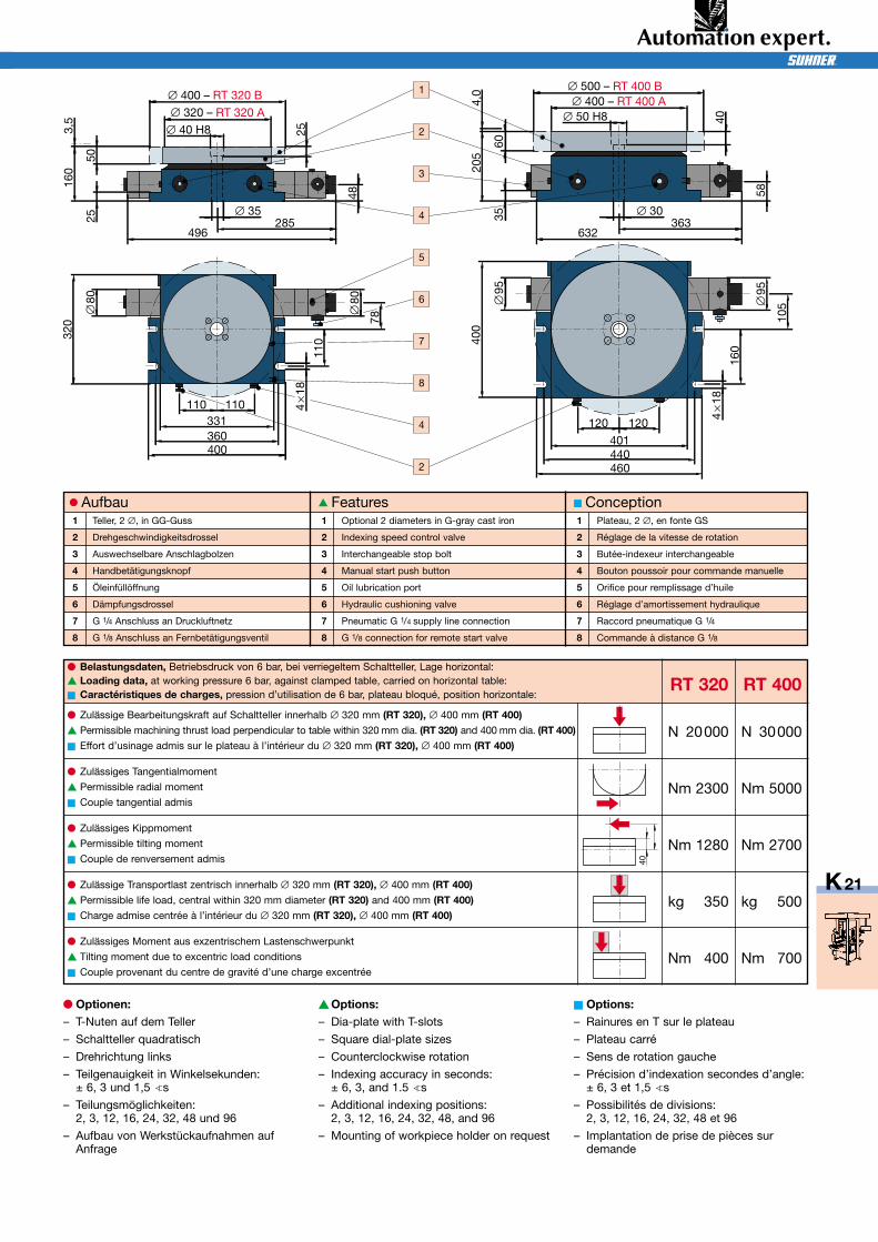
● Belastungsdaten, Betriebsdruck von 6 bar, bei verriegeltem Schaltteller, Lage horizontal:▲ Loading data, at working pressure 6 bar, against clamped table, carried on horizontal table:■ Caractéristiques de charges, pression d’utilisation de 6 bar, plateau bloqué, position horizontale:
RT 320 RT 400
● Aufbau1 Teller, 2 ∅, in GG-Guss
2 Drehgeschwindigkeitsdrossel
3 Auswechselbare Anschlagbolzen
4 Handbetätigungsknopf
5 Öleinfüllöffnung
6 Dämpfungsdrossel
7 G 1/4 Anschluss an Druckluftnetz
8 G 1/8 Anschluss an Fernbetätigungsventil
▲ Features1 Optional 2 diameters in G-gray cast iron
2 Indexing speed control valve
3 Interchangeable stop bolt
4 Manual start push button
5 Oil lubrication port
6 Hydraulic cushioning valve
7 Pneumatic G 1/4 supply line connection
8 G 1/8 connection for remote start valve
■ Conception1 Plateau, 2 ∅, en fonte GS
2 Réglage de la vitesse de rotation
3 Butée-indexeur interchangeable
4 Bouton poussoir pour commande manuelle
5 Orifice pour remplissage d’huile
6 Réglage d’amortissement hydraulique
7 Raccord pneumatique G 1/4
8 Commande à distance G 1/8
● Optionen:– T-Nuten auf dem Teller
– Schaltteller quadratisch
– Drehrichtung links
– Teilgenauigkeit in Winkelsekunden:± 6, 3 und 1,5 ?s
– Teilungsmöglichkeiten:2, 3, 12, 16, 24, 32, 48 und 96
– Aufbau von Werkstückaufnahmen aufAnfrage
▲Options:– Dia-plate with T-slots
– Square dial-plate sizes
– Counterclockwise rotation
– Indexing accuracy in seconds:± 6, 3, and 1.5 ?s
– Additional indexing positions:2, 3, 12, 16, 24, 32, 48, and 96
– Mounting of workpiece holder on request
■ Options:– Rainures en T sur le plateau
– Plateau carré
– Sens de rotation gauche
– Précision d’indexation secondes d’angle:± 6, 3 et 1,5 ?s
– Possibilités de divisions:2, 3, 12, 16, 24, 32, 48 et 96
– Implantation de prise de pièces surdemande
● Zulässige Bearbeitungskraft auf Schaltteller innerhalb ∅ 320 mm (RT 320), ∅ 400 mm (RT 400)▲ Permissible machining thrust load perpendicular to table within 320 mm dia. (RT 320) and 400 mm dia. (RT 400) N 20000 N 30000■ Effort d’usinage admis sur le plateau à l’intérieur du ∅ 320 mm (RT 320), ∅ 400 mm (RT 400)
● Zulässiges Tangentialmoment
▲ Permissible radial moment Nm 2300 Nm 5000■ Couple tangential admis
● Zulässiges Kippmoment
▲ Permissible tilting moment Nm 1280 Nm 2700■ Couple de renversement admis
● Zulässige Transportlast zentrisch innerhalb ∅ 320 mm (RT 320), ∅ 400 mm (RT 400)▲ Permissible life load, central within 320 mm diameter (RT 320) and 400 mm (RT 400) kg 350 kg 500■ Charge admise centrée à l’intérieur du ∅ 320 mm (RT 320), ∅ 400 mm (RT 400)
● Zulässiges Moment aus exzentrischem Lastenschwerpunkt
▲ Tilting moment due to excentric load conditions Nm 400 Nm 700■ Couple provenant du centre de gravité d’une charge excentrée
K20_K21_QX6.qxp:K60_K61 21.8.2008 14:33 Uhr Seite 21
S
6690°
∅12
8014
126°
∅27
62
> ∅ 1,5 mm> ∅ 0,3 mm
K50
MACHINEcomponents
BBK / BBG
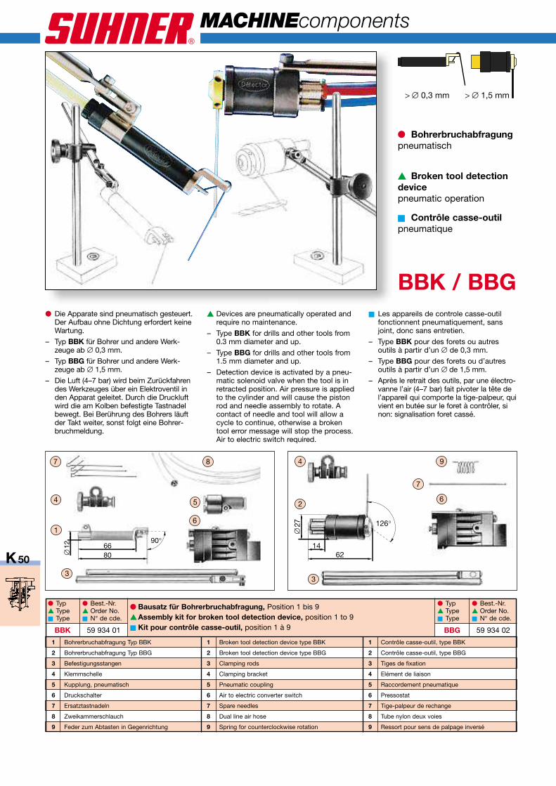
● Bohrerbruchabfragungpneumatisch
▲ Broken tool detectiondevicepneumatic operation
■ Contrôle casse-outilpneumatique
● Die Apparate sind pneumatisch gesteuert.Der Aufbau ohne Dichtung erfordert keineWartung.
– Typ BBK für Bohrer und andere Werk-zeuge ab ∅ 0,3 mm.
– Typ BBG für Bohrer und andere Werk-zeuge ab ∅ 1,5 mm.
– Die Luft (4–7 bar) wird beim Zurückfahrendes Werkzeuges über ein Elektroventil inden Apparat geleitet. Durch die Druckluftwird die am Kolben befestigte Tastnadelbewegt. Bei Berührung des Bohrers läuftder Takt weiter, sonst folgt eine Bohrer-bruchmeldung.
▲ Devices are pneumatically operated andrequire no maintenance.
– Type BBK for drills and other tools from0.3 mm diameter and up.
– Type BBG for drills and other tools from1.5 mm diameter and up.
– Detection device is activated by a pneu-matic solenoid valve when the tool is inretracted position. Air pressure is appliedto the cylinder and will cause the pistonrod and needle assembly to rotate. Acontact of needle and tool will allow acycle to continue, otherwise a brokentool error message will stop the process.Air to electric switch required.
■ Les appareils de controle casse-outilfonctionnent pneumatiquement, sansjoint, donc sans entretien.
– Type BBK pour des forets ou autresoutils à partir d’un ∅ de 0,3 mm.
– Type BBG pour des forets ou d’autresoutils à partir d’un ∅ de 1,5 mm.
– Après le retrait des outils, par une électro-vanne l’air (4–7 bar) fait pivoter la tête del’appareil qui comporte la tige-palpeur, quivient en butée sur le foret à contrôler, sinon: signalisation foret cassé.
1 Bohrerbruchabfragung Typ BBK
2 Bohrerbruchabfragung Typ BBG
3 Befestigungsstangen
4 Klemmschelle
5 Kupplung, pneumatisch
6 Druckschalter
7 Ersatztastnadeln
8 Zweikammerschlauch
9 Feder zum Abtasten in Gegenrichtung
● Bausatz für Bohrerbruchabfragung, Position 1 bis 9▲Assembly kit for broken tool detection device, position 1 to 9■ Kit pour contrôle casse-outil, position 1 à 9
● Typ ● Best.-Nr. ● Typ ● Best.-Nr.▲ Type ▲ Order No. ▲ Type ▲ Order No.■ Type ■ N° de cde. ■ Type ■ N° de cde.
BBK 59 934 01 BBG 59 934 02
1 Broken tool detection device type BBK
2 Broken tool detection device type BBG
3 Clamping rods
4 Clamping bracket
5 Pneumatic coupling
6 Air to electric converter switch
7 Spare needles
8 Dual line air hose
9 Spring for counterclockwise rotation
1 Contrôle casse-outil, type BBK
2 Contrôle casse-outil, type BBG
3 Tiges de fixation
4 Elément de liaison
5 Raccordement pneumatique
6 Pressostat
7 Tige-palpeur de rechange
8 Tube nylon deux voies
9 Ressort pour sens de palpage inversé
K50_K51_QX6.qxp:K60_K61 21.8.2008 14:34 Uhr Seite 50
K51
LUB 25
LUB 25
SP 24 V/ACSP 24 V/DCSP 110 V/ACSP 230 V/AC
DVM 25
Max. 300
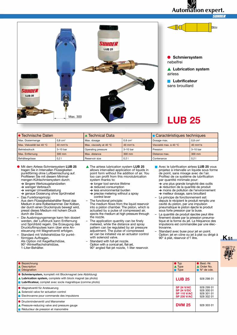
928 298 01
928 299 01928 300 01928 301 01928 302 01
928 303 01
● Mit dem Airless-Schmiersystem LUB 25tragen Sie in Intervallen Flüssigkeitenpunktförmig ohne Luftbeimischung auf.Profitieren Sie mit diesem Minimal-mengen-Kühlschmiersystem durch:➔ längere Werkzeugstandzeiten➔ weniger Verbrauch➔ weniger Umweltbelastung➔ genaue Dosierung ohne Sprühnebel
– Das Funktionsprinzip:Aus dem Flüssigkeitsbehälter fliesst dasMedium in eine Kolbenkammer. Der Kolben,der durch einen Druckimpuls bewegt wird,presst dieses Medium mit hohem Druckdurch die Düse.
– Die Ausbringungsmenge kann fein dosiertwerden, der Luftdruck kann Entfernungund Sprühbild regeln. Die Erzeugung desDruckluftimpulses kann über eine An-steuerung mit Magnetventil erfolgen.
– Standard mit Vollstrahldüse für punkt-förmiges Auftragen.Als Option mit Kegelflachdüse,90°-Winkelflachstrahldüse,1-Liter-Behälter.
▲ The airless lubrication system LUB 25allows intervalled application of liquids inpoint form without the addition of air. Youtoo can profit from this microlubricationsystem thanks to:➔ longer tool service lifetime➔ reduced consumption➔ less environmental burden➔ precise metering without a spray
control lever– The functional principle:
The medium flows from the liquid reservoirinto a piston chamber. The piston, which isactuated by a pulse of compressed air,ejects the medium at high pressure throughthe nozzle.
– The application quantity can be finelymetered, while the distance and spraypattern can be regulated by air pressureadjustment. The pulse of compressedair can be initiated via an actuator controlwith solenoid valve.
– Standard with full-jet nozzle.Option with a conical-jet, flat-jet,90° angled flat-jet nozzle, 1-liter reservoir.
■ Avec le lubrification airless LUB 25 vousprojetez à intervalle un liquide sous formede point, sans mixage avec de l’air.Profitez de ce système de lubrificationpar quantité minimale pour:➔ une plus grande longévité des outils➔ réduction de la quantité de produit➔ moins de pollution de l’environnement➔ meilleur dosage, sans brouillard
– Le principe de fonctionnement est:depuis le récipient le produit remplis unecavité du piston, par une impulsionpneumatique le piston éjecte le produitsous forte pression par la buse.
– La quantité de produit éjectée peut êtrefinement dosée par la pression pneuma-tique et la forme du jet. La fréquence desimpulsions est commandée par une élec-trovanne.
– Standard avec buse pour jet en point.Option: jet en cône ou jet à plat ou dirigé à90° à plat, réservoir d’1 litre.
● Technische DatenMax. Dosiermenge 0,8 cm3
Max. Viskosität bei 40 °C 40 mm2/s
Betriebsdruck 3–10 bar
Max. Entfernung 300 mm
Behältergrösse 0,2 l
▲ Technical DataMax. dosage 0.8 cm3
Max. viscosity at 40 °C 40 mm2/s
Operating pressure 3–10 bar
Max. distance 300 mm
Reservoir size 0.2 l
■ Caractéristiques techniquesDosage max. 0,8 cm3
Viscosité max. à 40 °C 40 mm2/s
Pression 3–10 bar
Distance max. 300 mm
Contenance 0,2 l
● Schmiersystemnebelfrei
▲ Lubrication systemairless
■ Lubrificateursans brouillard
● Schmiersystem, komplett mit Blockmagnet (wie Abbildung)▲ Lubrication system, complete with block magnet (as photo)■ Lubrificateur, complet avec socle magnétique (comme photo)
● Magnetventil für Ansteuerung▲ Solenoid valve for actuation control■ Electrovanne pour commande des impulsions
● Druckminderventil und Manometer▲ Pressure-reducing valve and pressure gauge■ Réducteur de pression et manomètre
● Bezeichnung ● Typ ● Best.-Nr.▲ Description ▲ Type ▲ Order No.■ Désignation ■ Type ■ N° de cde.
K50_K51_QX6.qxp:K60_K61 21.8.2008 14:34 Uhr Seite 51