Embed Size (px)
Citation preview
34
max
on
mo
tor
con
tro
l
Technik – kurz und bündig AusgabeApril2011/Änderungenvorbehalten
Dasmaxon motor controlProgrammbeinhaltetServoverstärkerzurAnsteuerungderreaktionsschnellenmaxonDC-undEC-Motoren.
Regelgrössen
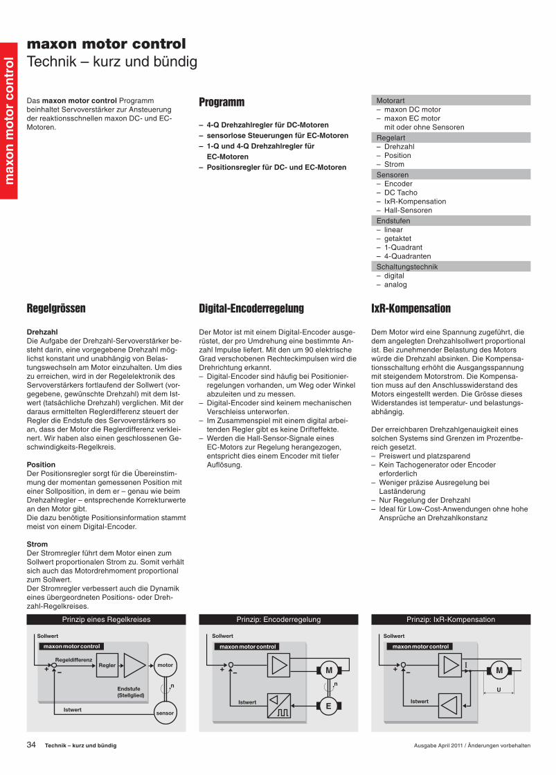
DrehzahlDieAufgabederDrehzahl-Servoverstärkerbe-stehtdarin,einevorgegebeneDrehzahlmög-lichstkonstantundunabhängigvonBelas-tungswechselnamMotoreinzuhalten.Umdieszuerreichen,wirdinderRegelelektronikdesServoverstärkersfortlaufendderSollwert(vor-gegebene,gewünschteDrehzahl)mitdemIst-wert(tatsächlicheDrehzahl)verglichen.MitderdarausermitteltenReglerdifferenzsteuertderReglerdieEndstufedesServoverstärkerssoan,dassderMotordieReglerdifferenzverklei-nert.WirhabenalsoeinengeschlossenenGe-schwindigkeits-Regelkreis.
PositionDerPositionsreglersorgtfürdieÜbereinstim-mungdermomentangemessenenPositionmiteinerSollposition,indemer–genauwiebeimDrehzahlregler–entsprechendeKorrekturwerteandenMotorgibt.DiedazubenötigtePositionsinformationstammtmeistvoneinemDigital-Encoder.
StromDerStromreglerführtdemMotoreinenzumSollwertproportionalenStromzu.SomitverhältsichauchdasMotordrehmomentproportionalzumSollwert.DerStromreglerverbessertauchdieDynamikeinesübergeordnetenPositions-oderDreh-zahl-Regelkreises.
PrinzipeinesRegelkreises Prinzip:Encoderregelung Prinzip:IxR-Kompensation
maxon motor controlTechnik–kurzundbündig
Digital-Encoderregelung
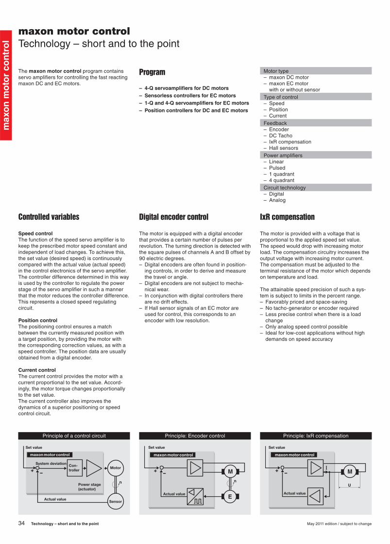
DerMotoristmiteinemDigital-Encoderausge-rüstet,derproUmdrehungeinebestimmteAn-zahlImpulseliefert.Mitdenum90elektrischeGradverschobenenRechteckimpulsenwirddieDrehrichtungerkannt.– Digital-EncodersindhäufigbeiPositionier-
regelungenvorhanden,umWegoderWinkelabzuleitenundzumessen.
– Digital-EncodersindkeinemmechanischenVerschleissunterworfen.
– ImZusammenspielmiteinemdigitalarbei-tendenReglergibteskeineDrifteffekte.
– WerdendieHall-Sensor-SignaleeinesEC-MotorszurRegelungherangezogen,entsprichtdieseinemEncodermittieferAuflösung.
Motorart– maxonDCmotor– maxonECmotor mitoderohneSensorenRegelart– Drehzahl– Position– StromSensoren– Encoder– DCTacho– IxR-Kompensation– Hall-SensorenEndstufen– linear– getaktet– 1-Quadrant– 4-QuadrantenSchaltungstechnik– digital– analog
Programm
– 4-Q Drehzahlregler für DC-Motoren– sensorlose Steuerungen für EC-Motoren– 1-Q und 4-Q Drehzahlregler für
EC-Motoren– Positionsregler für DC- und EC-Motoren
IxR-Kompensation
DemMotorwirdeineSpannungzugeführt,diedemangelegtenDrehzahlsollwertproportionalist.BeizunehmenderBelastungdesMotorswürdedieDrehzahlabsinken.DieKompensa-tionsschaltungerhöhtdieAusgangsspannungmitsteigendemMotorstrom.DieKompensa-tionmussaufdenAnschlusswiderstanddesMotorseingestelltwerden.DieGrössediesesWiderstandesisttemperatur-undbelastungs-abhängig.
DererreichbarenDrehzahlgenauigkeiteinessolchenSystemssindGrenzenimProzentbe-reichgesetzt.– Preiswertundplatzsparend– KeinTachogeneratoroderEncoder
erforderlich– WenigerpräziseAusregelungbei
Laständerung– NurRegelungderDrehzahl– IdealfürLow-Cost-Anwendungenohnehohe
AnsprücheanDrehzahlkonstanz
1104_Technology.indd34 10.02.201108:20:26

35
max
on
mo
tor
con
tro
l
AusgabeApril2011/Änderungenvorbehalten Technik – kurz und bündig
Prinzip:DC-Tacho-Regelung Betriebsquadranten Prinzip:getakteteEndstufe
Prinzip:LineareEndstufe
DC-Tacho-Regelung
DerMotormussmiteinemDC-Tachoausgerü-stetsein,dereindrehzahlproportionalesSignalliefert.Immaxon-BaukastensystemistderTacho-RotordirektaufderMotorwellemontiert,wodurcheinehoheResonanzfrequenzerreichtwird.– KlassischeLösungeinersehrpräzisen
Regelung– BegrenzteLebensdauerdes
DC-Tacho-Generators– NichtfürPositionieraufgabengeeignet– Nichtdigital– IdealfürhoheAnsprüchean
Drehzahldynamik
Betriebsquadranten
4-Q-Betrieb– KontrollierterMotorbetriebund
BremsbetriebinbeidenDrehrichtungen (alle4-Quadranten)– EinMussfürPositionieraufgaben
1-Q-Betrieb– NurMotorbetrieb
(QuadrantIoderQuadrantIII)– DrehrichtungsumkehrdurchdigitalesSignal– Typisch:VerstärkerfürEC-Motoren
Endstufen
ZurAnsteuerungderEndstufentransistorenarbeitendiemaxonReglernacheinemderbeidenfolgendenPrinzipien:
Lineare EndstufeDieBetriebsspannungwirdaufgeteiltzwischenMotorundEndstufe.DerReglerverändertdieSpannungamMotor(UM)linearundproportio-nal.DieanderEndstufeabfallendeSpannung(UT)verursachtVerlustleistung.– HoheStrömeundkleineMotorspannungen
verursachengrosseVerlustleistungen– EinfacherundpreisgünstigerAufbauder
Endstufe
Pulssteuerung (getaktet)DerReglerschaltetinkurzenIntervallen(Pulse/Takte)denMotoreinundaus.WirddasAus-Intervalllänger,verlangsamtderMotordieGeschwindigkeit.DermassgeblicheMittelwertderSpannungändertimVerhältnisderEin-zurAus-Zeit.NurwenigEnergiewirdinWärmeumgesetzt.– AufwändigereEndstufe– HoherWirkungsgradWeitereErgänzungensieheabSeite279.
1104_Technology.indd35 10.02.201108:20:26
34
max
on
mo
tor
con
tro
l
Technology – short and to the point May 2011 edition / subject to change
The maxon motor control program contains servo amplifiers for controlling the fast reacting maxon DC and EC motors.
Controlled variables
Speed controlThe function of the speed servo amplifier is to keep the prescribed motor speed constant and independent of load changes. To achieve this, the set value (desired speed) is continuously compared with the actual value (actual speed) in the control electronics of the servo amplifier. The controller difference determined in this way is used by the controller to regulate the power stage of the servo amplifier in such a manner that the motor reduces the controller difference. This represents a closed speed regulating circuit.
Position controlThe positioning control ensures a match between the currently measured position with a target position, by providing the motor with the corresponding correction values, as with a speed controller. The position data are usually obtained from a digital encoder.
Current controlThe current control provides the motor with a current proportional to the set value. Accord-ingly, the motor torque changes proportionally to the set value. The current controller also improves the dynamics of a superior positioning or speed control circuit.
Principle of a control circuit Principle: Encoder control Principle: IxR compensation
maxon motor controlTechnology – short and to the point
Digital encoder control
The motor is equipped with a digital encoder that provides a certain number of pulses per revolution. The turning direction is detected with the square pulses of channels A and B offset by 90 electric degrees.– Digital encoders are often found in position-
ing controls, in order to derive and measure the travel or angle.
– Digital encoders are not subject to mecha-nical wear.
– In conjunction with digital controllers there are no drift effects.
– If Hall sensor signals of an EC motor are used for control, this corresponds to an encoder with low resolution.
Motor type– maxon DC motor– maxon EC motor with or without sensorType of control– Speed– Position– CurrentFeedback– Encoder– DC Tacho– IxR compensation– Hall sensorsPower amplifiers– Linear– Pulsed– 1 quadrant– 4 quadrantCircuit technology– Digital– Analog
Program
– 4-Q servoamplifiers for DC motors– Sensorless controllers for EC motors– 1-Q and 4-Q servoamplifiers for EC motors– Position controllers for DC and EC motors
IxR compensation
The motor is provided with a voltage that is proportional to the applied speed set value. The speed would drop with increasing motor load. The compensation circuitry increases the output voltage with increasing motor current. The compensation must be adjusted to the terminal resistance of the motor which depends on temperature and load.
The attainable speed precision of such a sys-tem is subject to limits in the percent range.– Favorably priced and space-saving– No tacho-generator or encoder required– Less precise control when there is a load
change– Only analog speed control possible– Ideal for low-cost applications without high
demands on speed accuracy
35
max
on
mo
tor
con
tro
l
May 2011 edition / subject to change Technology – short and to the point
Principle: Linear power amplifier
Principle: DC tachometer control Operation quadrants Principle: Pulsed power amplifier
DC tacho control
The motor must be equipped with a DC tachom-eter that provides a speed proportional signal. In the maxon modular system, the tachometer rotor is mounted directly on the through motor shaft, resulting in a high resonant frequency.– Classical solution of a very precise control– Limited service life of the DC tacho
generator– Not suitable for positioning tasks– Only for analog controllers– Only for DC motors– Ideal for stringent demands on speed
dynamics
Operating quadrants
4-Q operation– Controlled motor operation and braking
operation in both rotation directions– A must for positioning tasks
1-Q operation– Only motor operation
(Quadrant I or Quadrant III)– Direction reverse via digital signal– Typical: amplifier for EC motors
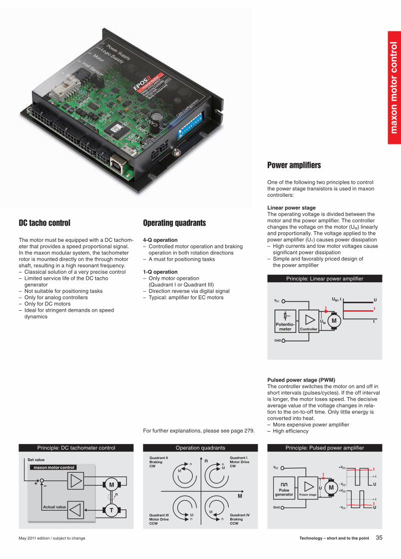
Power amplifiers
One of the following two principles to control the power stage transistors is used in maxon controllers:
Linear power stageThe operating voltage is divided between the motor and the power amplifier. The controller changes the voltage on the motor (UM) linearly and proportionally. The voltage applied to the power amplifier (UT) causes power dissipation– High currents and low motor voltages cause
significant power dissipation– Simple and favorably priced design of
the power amplifier
Pulsed power stage (PWM)The controller switches the motor on and off in short intervals (pulses/cycles). If the off interval is longer, the motor loses speed. The decisive average value of the voltage changes in rela-tion to the on-to-off time. Only little energy is converted into heat.– More expensive power amplifier– High efficiencyFor further explanations, please see page 279.
34
max
on
mo
tor
con
tro
l
Tecnología – breve y conciso Edicióndejuliode2012/Sujetoamodificaciones
Elprogramamaxon motor controlincluyeservoamplificadoresdecontrolparalosmotoresdereacciónrápidamaxonDCyEC.
Variables controladas
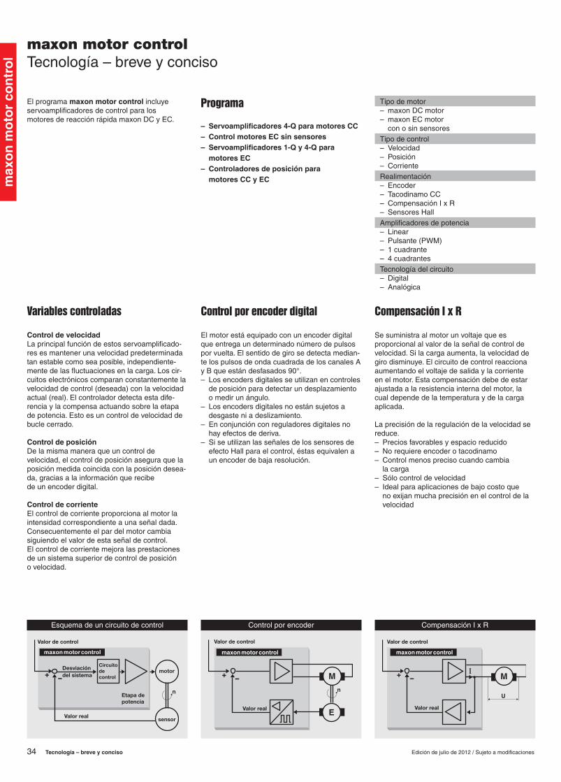
Control de velocidadLaprincipalfuncióndeestosservoamplificado-resesmantenerunavelocidadpredeterminadatanestablecomoseaposible,independiente-mentedelasfluctuacionesenlacarga.Loscir-cuitoselectrónicoscomparanconstantementelavelocidaddecontrol(deseada)conlavelocidadactual(real).Elcontroladordetectaestadife-renciaylacompensaactuandosobrelaetapadepotencia.Estoesuncontroldevelocidaddebuclecerrado.
Control de posiciónDelamismamaneraqueuncontroldevelocidad,elcontroldeposiciónaseguraquelaposiciónmedidacoincidaconlaposicióndesea-da,graciasalainformaciónquerecibedeunencoderdigital.
Control de corrienteElcontroldecorrienteproporcionaalmotorlaintensidadcorrespondienteaunaseñaldada.Consecuentementeelpardelmotorcambiasiguiendoelvalordeestaseñaldecontrol.Elcontroldecorrientemejoralasprestacionesdeunsistemasuperiordecontroldeposiciónovelocidad.
Esquemadeuncircuitodecontrol Controlporencoder CompensaciónIxR
maxon motor controlTecnología–breveyconciso
Control por encoder digital
Elmotorestáequipadoconunencoderdigitalqueentregaundeterminadonúmerodepulsosporvuelta.Elsentidodegirosedetectamedian-telospulsosdeondacuadradadeloscanalesAyBqueestándesfasados90°.– Losencodersdigitalesseutilizanencontroles
deposiciónparadetectarundesplazamientoomedirunángulo.
– Losencodersdigitalesnoestánsujetosadesgasteniadeslizamiento.
– Enconjunciónconreguladoresdigitalesnohayefectosdederiva.
– SiseutilizanlasseñalesdelossensoresdeefectoHallparaelcontrol,éstasequivalenaunencoderdebajaresolución.
Tipodemotor– maxonDCmotor– maxonECmotor conosinsensoresTipodecontrol– Velocidad– Posición– CorrienteRealimentación– Encoder– TacodinamoCC– CompensaciónIxR– SensoresHallAmplificadoresdepotencia– Linear– Pulsante(PWM)– 1cuadrante– 4cuadrantesTecnologíadelcircuito– Digital– Analógica
Programa
– Servoamplificadores 4-Q para motores CC– Control motores EC sin sensores– Servoamplificadores 1-Q y 4-Q para
motores EC– Controladores de posición para
motores CC y EC
Compensación I x R
Sesuministraalmotorunvoltajequeesproporcionalalvalordelaseñaldecontroldevelocidad.Silacargaaumenta,lavelocidaddegirodisminuye.Elcircuitodecontrolreaccionaaumentandoelvoltajedesalidaylacorrienteenelmotor.Estacompensacióndebedeestarajustadaalaresistenciainternadelmotor,lacualdependedelatemperaturaydelacargaaplicada.
Laprecisióndelaregulacióndelavelocidadsereduce.– Preciosfavorablesyespacioreducido– Norequiereencoderotacodinamo– Controlmenosprecisocuandocambia
lacarga– Sólocontroldevelocidad– Idealparaaplicacionesdebajocostoque
noexijanmuchaprecisiónenelcontroldelavelocidad
1204_Technology.indd34 11.07.201209:54:16
35
max
on
mo
tor
con
tro
l
Edicióndejuliode2012/Sujetoamodificaciones Tecnología – breve y conciso
RegulaciónportacodinamoCC Funcionamientoen4Cuadrantes Amplificadorpulsante(PWM)
ReguladorPotenció-
mentro
Etapadepotencialineal
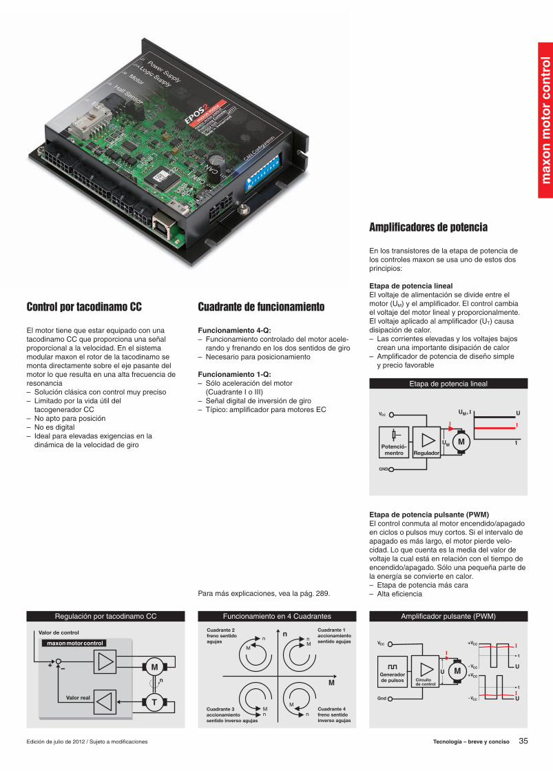
Control por tacodinamo CC
ElmotortienequeestarequipadoconunatacodinamoCCqueproporcionaunaseñalproporcionalalavelocidad.Enelsistemamodularmaxonelrotordelatacodinamosemontadirectamentesobreelejepasantedelmotorloqueresultaenunaaltafrecuenciaderesonancia– Soluciónclásicaconcontrolmuypreciso– Limitadoporlavidaútildel
tacogeneradorCC– Noaptoparaposición– Noesdigital– Idealparaelevadasexigenciasenla
dinámicadelavelocidaddegiro
Cuadrante de funcionamiento
Funcionamiento 4-Q:– Funcionamientocontroladodelmotoracele-
randoyfrenandoenlosdossentidosdegiro– Necesarioparaposicionamiento
Funcionamiento 1-Q:– Sóloaceleracióndelmotor
(CuadranteIoIII)– Señaldigitaldeinversióndegiro– Típico:amplificadorparamotoresEC
Amplificadores de potencia
Enlostransistoresdelaetapadepotenciadeloscontrolesmaxonseusaunodeestosdosprincipios:
Etapa de potencia linealElvoltajedealimentaciónsedivideentreelmotor(UM)yelamplificador.Elcontrolcambiaelvoltajedelmotorlinealyproporcionalmente.Elvoltajeaplicadoalamplificador(UT)causadisipacióndecalor.– Lascorrienteselevadasylosvoltajesbajos
creanunaimportantedisipacióndecalor– Amplificadordepotenciadediseñosimple
ypreciofavorable
Etapa de potencia pulsante (PWM)Elcontrolconmutaalmotorencendido/apagadoenciclosopulsosmuycortos.Sielintervalodeapagadoesmáslargo,elmotorpierdevelo-cidad.Loquecuentaeslamediadelvalordevoltajelacualestáenrelaciónconeltiempodeencendido/apagado.Sólounapequeñapartedelaenergíaseconvierteencalor.– Etapadepotenciamáscara– AltaeficienciaParamásexplicaciones,vealapág.289.
1204_Technology.indd35 11.07.201209:54:17