Embed Size (px)
Citation preview
Changeover Support
MOVIDRIVE_A
MOVIDRIVE compact to MOVIDRIVE 60/61 B
Sizes 0-6
November 2003
Authors: Helmut Keller GE-ATS Gerald Schneeloch GE-ATS
Ad_02046

GE-ATS / Keller / Schneeloch / Ad_02046 Umstellungshilfe MCX und MDX_A auf MDX60/61B Seite 2 von 21
This document has been prepared on the basis of the current status of knowledge. Consequently, subsequent discoveries may lead to different statements. As a result, the possibility of misinterpretations or mistakes in the technical data cannot be ruled out.
GE-ATS / Keller / Schneeloch / Ad_02046 Umstellungshilfe MCX und MDX_A auf MDX60/61B Seite 3 von 21
Preface This document is intended to support sales activities by dealing with current and general questions relating to technology and the project planning of products. Please do not hesitate to contact the authors if you have any questions or suggestions. Authors: Helmut Keller 07251 / 75 - 1115 Gerald Schneeloch 07251 / 75 ° 1185
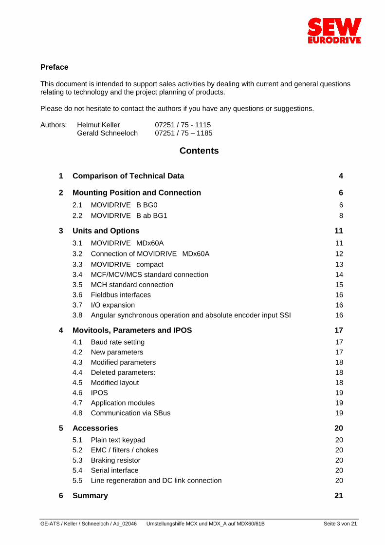
Contents
1 Comparison of Technical Data 4
2 Mounting Position and Connection 6 2.1 MOVIDRIVE B BG0 6 2.2 MOVIDRIVE B ab BG1 8
3 Units and Options 11 3.1 MOVIDRIVE MDx60A 11 3.2 Connection of MOVIDRIVE MDx60A 12 3.3 MOVIDRIVE compact 13 3.4 MCF/MCV/MCS standard connection 14 3.5 MCH standard connection 15 3.6 Fieldbus interfaces 16 3.7 I/O expansion 16 3.8 Angular synchronous operation and absolute encoder input SSI 16
4 Movitools, Parameters and IPOS 17 4.1 Baud rate setting 17 4.2 New parameters 17 4.3 Modified parameters 18 4.4 Deleted parameters: 18 4.5 Modified layout 18 4.6 IPOS 19 4.7 Application modules 19 4.8 Communication via SBus 19
5 Accessories 20 5.1 Plain text keypad 20 5.2 EMC / filters / chokes 20 5.3 Braking resistor 20 5.4 Serial interface 20 5.5 Line regeneration and DC link connection 20
6 Summary 21
GE-ATS/ Keller / Schneeloch / Ad_02046 Umstellungshilfe MCX und MDX_A auf MDX60/61B Seite 4 von 21
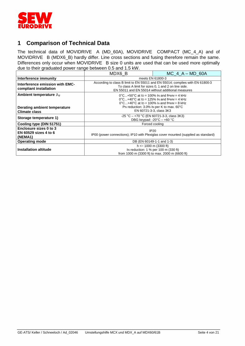
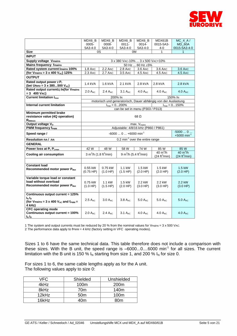
1 Comparison of Technical Data The technical data of MOVIDRIVE A (MD_60A), MOVIDRIVE COMPACT (MC_4_A) and of MOVIDRIVE B (MDX6_B) hardly differ. Line cross sections and fusing therefore remain the same. Differences only occur when MOVIDRIVE B size 0 units are used that can be used more optimally due to their graduated power range between 0.5 and 1.5 kW. MDX6_B MC_4_A ° MD_60A Interference immunity meets EN 61800-3
Interference emission with EMC-compliant installation
According to class B limit to EN 55011 and EN 55014; complies with EN 61800-3 To class A limit for sizes 0, 1 and 2 on line side.
EN 55011 and EN 55014 without additional measures Ambient temperature ϑU Derating ambient temperature Climate class
0äC...+50äC at ID = 100% IN and fPWM = 4 kHz 0äC...+40äC at ID = 125% IN and fPWM = 4 kHz 0äC...+40äC at ID = 100% In and fPWM = 8 kHz
PN reduction: 3.0% IN per K to max. 60äC EN 60721-3-3, class 3K3
Storage temperature 1) -25 äC ° +70 äC (EN 60721-3-3, class 3K3) DBG keypad: -20äC ° +60 äC
Cooling type (DIN 51751) Forced cooling Enclosure sizes 0 to 3 EN 60529 sizes 4 to 6 (NEMA1)
IP20 IP00 (power connections); IP10 with Plexiglas cover mounted (supplied as standard)
Operating mode DB (EN 60149-1-1 and 1-3)
Installation altitude h <= 1000 m (3300 ft)
IN reduction: 1 % per 100 m (330 ft) from 1000 m (3300 ft) to max. 2000 m (6600 ft)
GE-ATS / Keller / Schneeloch / Ad_02046 Umstellungshilfe MCX und MDX_A auf MDX60/61B Seite 5 von 21
MDX6_B
0005-5A3-4-0
MDX6_B 0008-
5A3-4-0
MDX6_B 0011-
5A3-4-0
MDX6_B 0014-
5A3-4-0
MDX61B 0015-5A3-
4-0
MC_4_A / MD_60A
0015-5A3-4-0 Size 0S 0M 1 1 INPUT Supply voltage Vmains 3 x 380 VAC-10% ... 3 x 500 VAC+10% Mains frequency fmains 50 Hz ... 60 Hz ±5% Rated system current Imains 100% 1.8 AAC 2.2 AAC 2.8 AAC 3.6 AAC 3.6 AAC 3.6 AAC (for Vmains = 3 x 400 VAC) 125% 2.3 AAC 2.7 AAC 3.5 AAC 4.5 AAC 4.5 AAC 4.5 AAC OUTPUT Rated output power 2 Pr (bei UNetz = 3 x 380...500 VAC) 1.4 kVA 1.6 kVA 2.1 kVA 2.8 kVA 2.8 kVA 2.8 kVA
Rated output current1) IN(for Vmains = 3 ⋅ 400 VAC) 2.0 AAC 2.4 AAC 3.1 AAC 4.0 AAC 4.0 AAC 4.0 AAC
Current limitation Imax 200% IN 150% IN motorisch und generatorisch, Dauer abha ngig von der Auslastung Internal current limitation Imax = 0...200% Imax = 0...150% can be set in menu (P303 / P313) Minimum permitted brake resistance value (4Q operation) RBWmin
68 Ø
Output voltage VO max. Vmains PWM frequency fPWM Adjustable: 4/8/16 kHz (P860 / P861) Speed range / -6000 ... 0 ... +6000 min-1 -5000 ... 0 ...
+5000 min-1 Resolution nA / .nA 0.2 min-1 over the entire range GENERAL Power loss at PL PLmax 42 W 48 W 58 W 74 W 85 W 85 W
Cooling air consumption 3 m3/h (1.8 ft3/min) 9 m3/h (5.4 ft3/min) 40 m3/h (24 ft3/min)
40 m3/h (24 ft3/min)
Constant load Recommended motor power PMot
0.55 kW (0.75 HP)
0.75 kW (1.0 HP)
1.1 kW (1.5 HP)
1.5 kW (2.0 HP)
1.5 kW (2.0 HP)
1.5 kW (2.0 HP)
Variable torque load or constant load without overload Recommended motor power PMot
0.75 kW (1.0 HP)
1.1 kW (1.5 HP)
1.5 kW (2.0 HP)
2.2 kW (3.0 HP)
2.2 kW (3.0 HP)
2.2 kW (3.0 HP)
Continuous output current = 125% IN ID (for Vmains = 3 x 400 VAC and fPWM = 4 kHz)
2.5 AAC 3.0 AAC 3.8 AAC 5.0 AAC 5.0 AAC 5.0 AAC
CFC operating mode Continuous output current = 100% IN ID
2.0 AAC 2.4 AAC 3.1 AAC 4.0 AAC 4.0 AAC 4.0 AAC
1 The system and output currents must be reduced by 20 % from the nominal values for Vmains = 3 x 500 VAC. 2 The performance data apply to fPWM = 4 kHz (factory setting in VFC operating modes). Sizes 1 to 6 have the same technical data. This table therefore does not include a comparison with these sizes. With the B unit, the speed range is ° 6000...0....6000 min-1 for all sizes. The current limitation with the B unit is 150 % IN starting from size 1, and 200 % IN for size 0. For sizes 1 to 6, the same cable lengths apply as for the A unit. The following values apply to size 0:
VFC Shielded Unshielded 4kHz 100m 200m 8kHz 70m 140m 12kHz 50m 100m 16kHz 40m 80m
GE-ATS/ Keller / Schneeloch / Ad_02046 Umstellungshilfe MCX und MDX_A auf MDX60/61B Seite 6 von 21
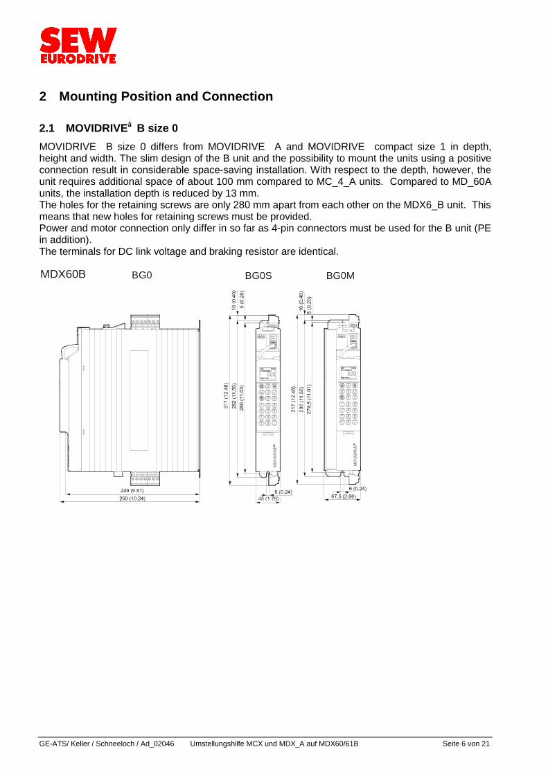
2 Mounting Position and Connection 2.1 MOVIDRIVE B size 0 MOVIDRIVE B size 0 differs from MOVIDRIVE A and MOVIDRIVE compact size 1 in depth, height and width. The slim design of the B unit and the possibility to mount the units using a positive connection result in considerable space-saving installation. With respect to the depth, however, the unit requires additional space of about 100 mm compared to MC_4_A units. Compared to MD_60A units, the installation depth is reduced by 13 mm. The holes for the retaining screws are only 280 mm apart from each other on the MDX6_B unit. This means that new holes for retaining screws must be provided. Power and motor connection only differ in so far as 4-pin connectors must be used for the B unit (PE in addition). The terminals for DC link voltage and braking resistor are identical. MDX60B BG0 BG0S BG0M
GE-ATS / Keller / Schneeloch / Ad_02046 Umstellungshilfe MCX und MDX_A auf MDX60/61B Seite 7 von 21
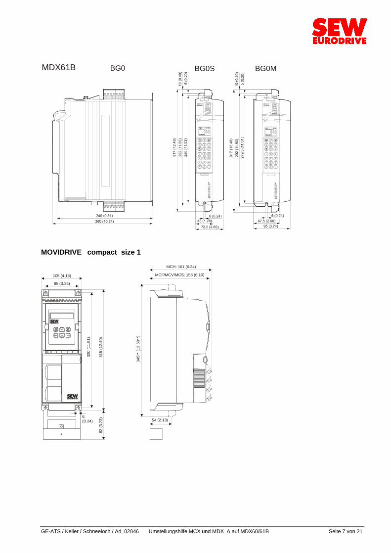
MDX61B BG0 BG0S BG0M
MOVIDRIVE compact size 1
82 (3
.23) 54 (2.13)
85 (3.35)
105 (4.13)
6(0.24)
300
(11.
81)
315
(12.
40)
MCF/MCV/MCS: 155 (6.10)
MCH: 161 (6.34)
345*
* (13
.58*
*)
*
GE-ATS/ Keller / Schneeloch / Ad_02046 Umstellungshilfe MCX und MDX_A auf MDX60/61B Seite 8 von 21
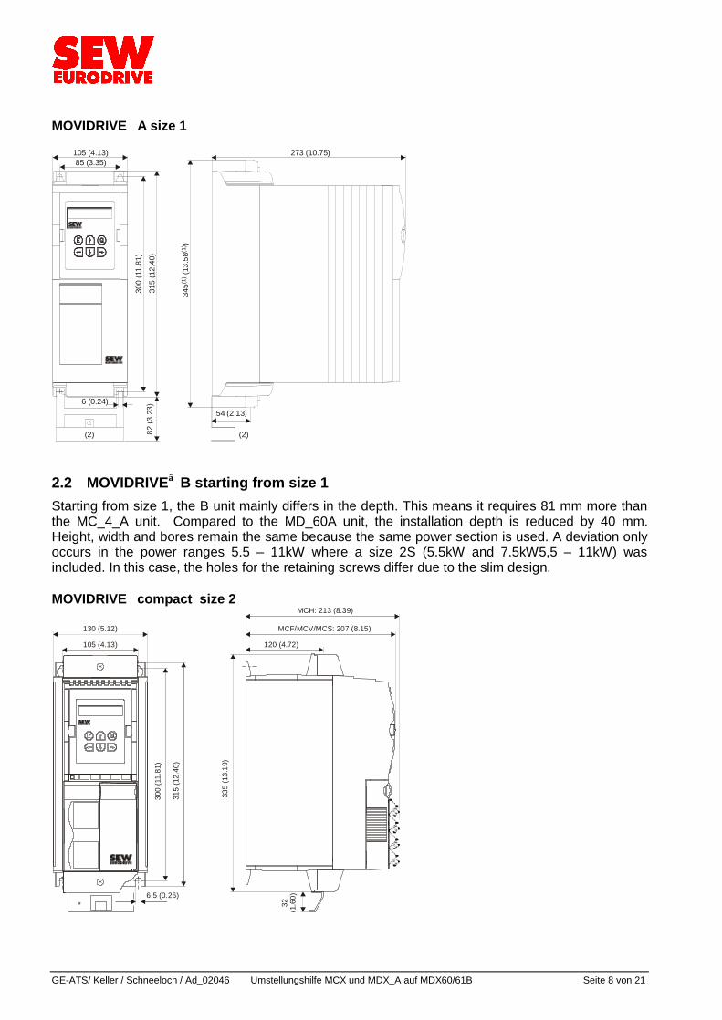
MOVIDRIVE A size 1
85 (3.35)105 (4.13) 273 (10.75)
6 (0.24)
300
(11.
81)
315
(12.
40)
345
(13.
58)
(1)
(1)
82 (3
.23) 54 (2.13)
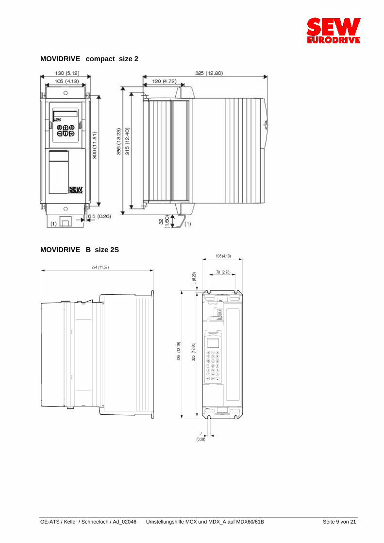
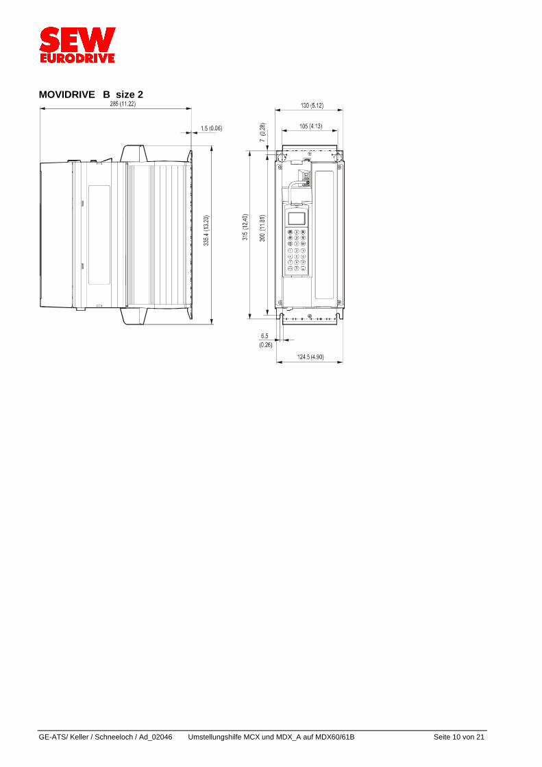
(2) (2) 2.2 MOVIDRIVE B starting from size 1 Starting from size 1, the B unit mainly differs in the depth. This means it requires 81 mm more than the MC_4_A unit. Compared to the MD_60A unit, the installation depth is reduced by 40 mm. Height, width and bores remain the same because the same power section is used. A deviation only occurs in the power ranges 5.5 ° 11kW where a size 2S (5.5kW and 7.5kW5,5 ° 11kW) was included. In this case, the holes for the retaining screws differ due to the slim design. MOVIDRIVE compact size 2
130 (5.12)
105 (4.13)
MCF/MCV/MCS: 207 (8.15)
300
(11.
81)
315
(12.
40)
335
(13.
19)
6.5 (0.26)
32(1
.60)
120 (4.72)
*
MCH: 213 (8.39)
GE-ATS / Keller / Schneeloch / Ad_02046 Umstellungshilfe MCX und MDX_A auf MDX60/61B Seite 9 von 21
MOVIDRIVE compact size 2
MOVIDRIVE B size 2S
GE-ATS/ Keller / Schneeloch / Ad_02046 Umstellungshilfe MCX und MDX_A auf MDX60/61B Seite 10 von 21
MOVIDRIVE B size 2
GE-ATS / Keller / Schneeloch / Ad_02046 Umstellungshilfe MCX und MDX_A auf MDX60/61B Seite 11 von 21
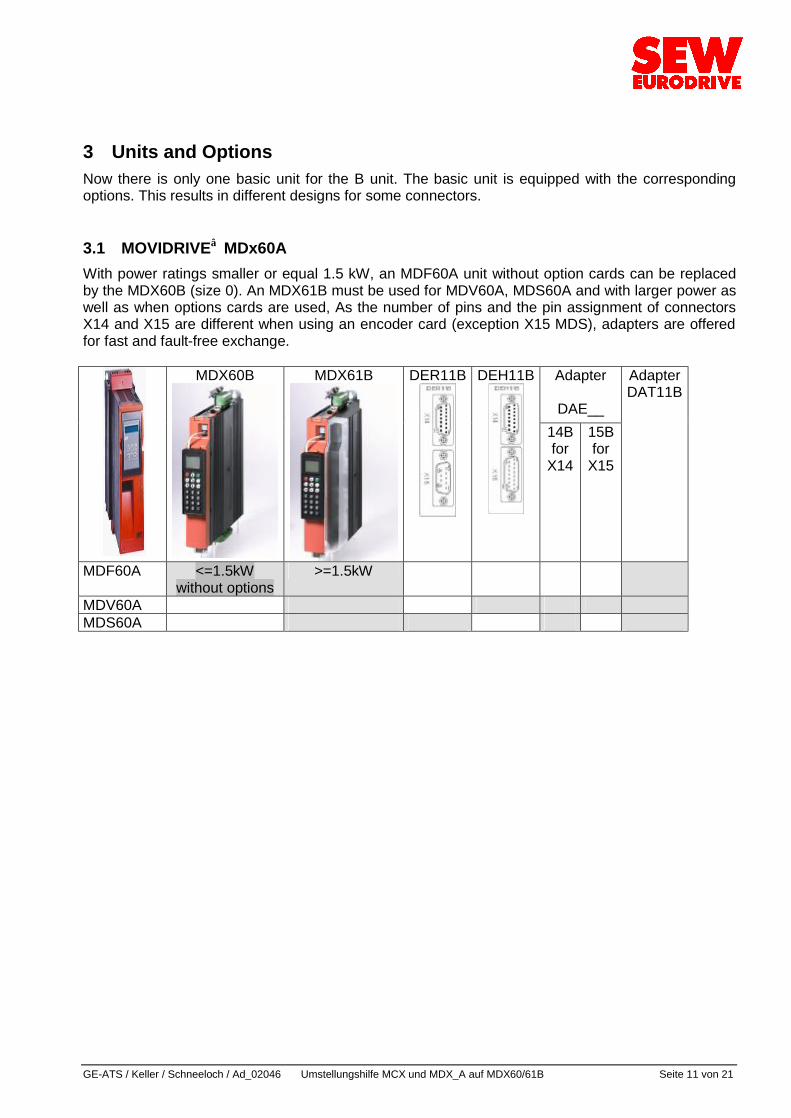
3 Units and Options Now there is only one basic unit for the B unit. The basic unit is equipped with the corresponding options. This results in different designs for some connectors. 3.1 MOVIDRIVE MDx60A With power ratings smaller or equal 1.5 kW, an MDF60A unit without option cards can be replaced by the MDX60B (size 0). An MDX61B must be used for MDV60A, MDS60A and with larger power as well as when options cards are used, As the number of pins and the pin assignment of connectors X14 and X15 are different when using an encoder card (exception X15 MDS), adapters are offered for fast and fault-free exchange.
Adapter
DAE__
MDX60B
MDX61B
DER11B
DEH11B
14B for
X14
15B for
X15
Adapter DAT11B
MDF60A <=1.5kW without options
>=1.5kW
MDV60A MDS60A
GE-ATS/ Keller / Schneeloch / Ad_02046 Umstellungshilfe MCX und MDX_A auf MDX60/61B Seite 12 von 21
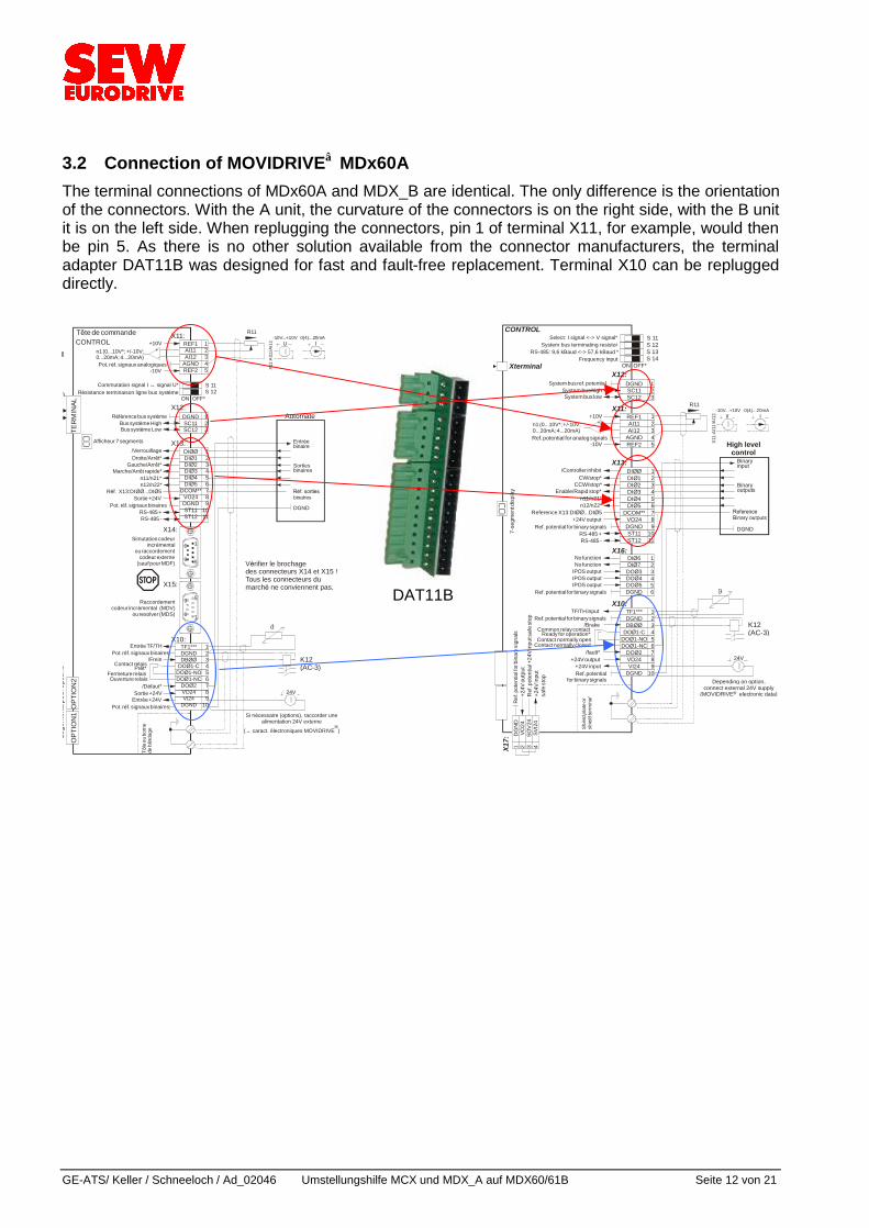
3.2 Connection of MOVIDRIVE MDx60A The terminal connections of MDx60A and MDX_B are identical. The only difference is the orientation of the connectors. With the A unit, the curvature of the connectors is on the right side, with the B unit it is on the left side. When replugging the connectors, pin 1 of terminal X11, for example, would then be pin 5. As there is no other solution available from the connector manufacturers, the terminal adapter DAT11B was designed for fast and fault-free replacement. Terminal X10 can be replugged directly.
n11/n21*n12/n22*
DGND
X14:
X15:
TER
MIN
AL
-10V
+10V+-
n1 (0...10V*; +/-10V;0...20mA; 4...20mA)
X11:
X12:
REF1AI11AI12
AGNDREF2
12345
DGNDSC11SC12
123
S 11S 12
X13:DIêêDIê1DIê2DIê3DIê4DIê5
DCOM**VO24DGNDST11ST12
123456789
1011RS-485 -
RS-485 +
X10:
K12(AC-3)
TF1***DGNDDBêê
DOê1-CDOê1-NODOê1-NC
DOê2VO24VI24
DGND
123456789
10
R11-10V...+10V 0(4)...20mA
I
X11:
AI1
1/AI
12
ON OFF*
1
5
6
9
5
1
9
6
ϑ
24V
TERMINAL
CONTROL
E Q
OPT
ION
2O
PTIO
N1
Te te de commande
console param.
Automate
Entr´ebinaire
Sortiesbinaires
Affichage 7 segmentsEtat de fonctionnement
R´glage-usine en cours
Afficheur 7 segments
Simutation codeur incr´mental
ou raccordementcodeur externe
(sauf pour MDF)
Pot. r´ f. signaux analogiques
R´ f´ rence bus syst̀ meBus syst` me HighBus syst` me Low
Commutation signal I signal U*R´ sistance terminaison ligne bus syst̀ me
↔
Pot. r´ f. signaux binaires
Marche/Arre t rapide*
/VerrouillageDroite/Arre t*
Gauche/Arre t*
R´ f. X13:DIêê ...DIê5
Loge
men
ts po
ur o
ptio
ns
Tole
ou
born
ede
blin
dage
Raccordementcodeur incr´mental (MDV)
ou resolver (MDS)
Pot. r´ f. signaux binaires
Pot. r´ f. signaux binairesEntr´e +24V
Entr´e TF/TH
Contact relaisPre t*
Ouverture relaisFermeture relais
/Frein
/D´ faut*
U
Sortie +24V
Sortie +24V
V´ rifier le brochagedes connecteurs X14 et X15 !Tous les connecteurs dumarch´ ne conviennent pas.
Si n´ cessaire (options), raccorder unealimentation 24V externe
( caract. ´ lectroniques MOVIDRIVE )→“
Xterminal
-10V
+10V+-
n1 (0...10V*; +/-10V;0...20mA; 4...20mA)
X11:REF1AI11AI12
AGNDREF2
12345
R11-10V...+10V 0(4)...20mA
I
X11:
AI11
/AI1
2
X12:DGNDSC11SC12
123
S 13S 14
S 11S 12
ON OFF*
X16:
X10:
DI 6DI 7DOê3DOê4DOê5DGND
êê
123456
K12(AC-3)
TF1***DGNDDBêê
DOê1-CDOê1-NODOê1-NC
DOê2VO24VI24
DGND
123456789
10
24V
CONTROL
n11/n21*n12/n22*
DGND
X13:DIêêDIê1DIê2DIê3DIê4DIê5
DCOM**VO24DGNDST11ST12
123456789
1011RS-485 -
RS-485 +0123456789AbcdEFH
running (blinking
RS-232
X17:
DG
ND
VO24
SOV
24SV
I24
1 2 3 4
OptionDBG60BKeypad
OptionUWS21A
High levelcontrol
Binaryinput
Binaryoutputs
7-segment displayOperating condition
Current as standstill
Limit switch approached
Fault indication (flashing)
7-se
gmen
t dis
play
Ref. potential for analog signals
System bus ref. potentialSystem bus highSystem bus low
Select: I signal <-> V signal*System bus terminating resistor
RS-485: 9,6 kBaud <-> 57,6 kBaudFrequency input
*
Ref. potential for binary signals
Ref. potential for binary signals
Enable/Rapid stop*
/Controller inhibit
No function
IPOS outputIPOSIPOS
No function
output output
CW/stop*CCW/stop*
Reference X13:DIêê...DIê5
Shie
ld p
late
or
shie
ld te
rmin
al
Ref. potential for binary signals
Ref. potentialfor binary signals
+24V input
TF/TH input
Common relay contactReady for operation*
Contact normally closedContact normally open
/Brake
/fault*
V
+24V output
+24V output
Ref
. pot
entia
l for b
inar
y sig
nals
+24V
out
put
Ref
. pot
entia
l +24
V in
put s
afe
stop
+24V
inpu
tsa
fe st
op Depending on option,connect external 24V supply
(MOVIDRIVE electronic data)“
DAT11B
GE-ATS / Keller / Schneeloch / Ad_02046 Umstellungshilfe MCX und MDX_A auf MDX60/61B Seite 13 von 21
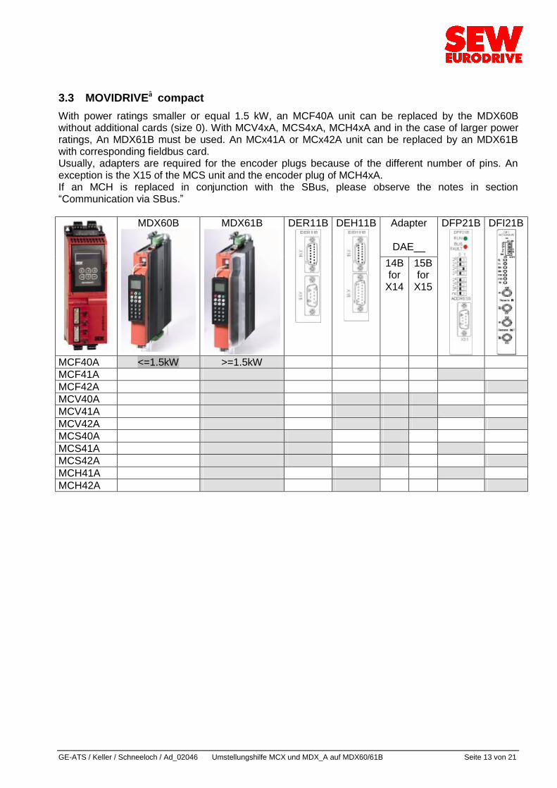
3.3 MOVIDRIVE compact With power ratings smaller or equal 1.5 kW, an MCF40A unit can be replaced by the MDX60B without additional cards (size 0). With MCV4xA, MCS4xA, MCH4xA and in the case of larger power ratings, An MDX61B must be used. An MCx41A or MCx42A unit can be replaced by an MDX61B with corresponding fieldbus card. Usually, adapters are required for the encoder plugs because of the different number of pins. An exception is the X15 of the MCS unit and the encoder plug of MCH4xA. If an MCH is replaced in conjunction with the SBus, please observe the notes in section ”Communication via SBus.ß
Adapter
DAE__
MDX60B
MDX61B
DER11B
DEH11B
14B for
X14
15B for
X15
DFP21B
DFI21B
MCF40A <=1.5kW >=1.5kW MCF41A MCF42A MCV40A MCV41A MCV42A MCS40A MCS41A MCS42A MCH41A MCH42A
GE-ATS/ Keller / Schneeloch / Ad_02046 Umstellungshilfe MCX und MDX_A auf MDX60/61B Seite 14 von 21
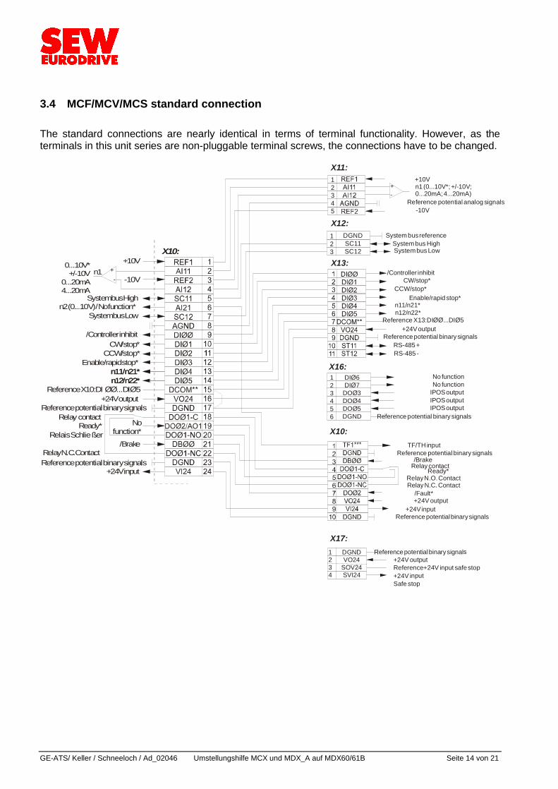
3.4 MCF/MCV/MCS standard connection The standard connections are nearly identical in terms of terminal functionality. However, as the terminals in this unit series are non-pluggable terminal screws, the connections have to be changed.
n11/n21*n12/n22*
X10:
n11/n21*n12/n22*
-10V
+10V+-
0...10V* +/-10V
0...20mA 4...20mA
n1
Enable/rapid stop*
/Controller inhibit
n2 (0...10 V) / No function*
CW/stop*CCW/stop*
Reference X10:DI êê...DIê5
Reference potential binary signals
Reference potential binary signals+24V input
Relay contactReady*
Relay N.C. Contact
Relais Schlieᄑer/Brake
Nofunction*
+24V output
System bus Low
System bus High
-10V
+10Vn1 (0...10V*; +/-10V;0...20mA; 4...20mA)
X11:12345
Reference potential analog signals
Reference potential binary signals
Reference potential binary signals+24V input
TF/TH input
Relay contactReady*
Relay N.C. ContactRelay N.O. Contact
/Brake
/Fault*+24V output
X10:
n11/n21*n12/n22*
RS-485 -RS-485 +
Reference potential binary signals
Enable/rapid stop*
/Controller inhibitCW/stop*
CCW/stop*
Reference X13:DIêê ...DIê5+24V output
X13:
X12:DGNDSC11SC12
123
System bus referenceSystem bus HighSystem bus Low
X16:DI 6DI 7
DOê3DOê4DOê5DGND
êê
123456 Reference potential binary signals
No functionNo function
IPOS outputIPOS outputIPOS output
X17:DGNDVO24
SOV24SVI24
1234
Reference potential binary signals+24V outputReference+24V input safe stop+24V inputSafe stop
GE-ATS / Keller / Schneeloch / Ad_02046 Umstellungshilfe MCX und MDX_A auf MDX60/61B Seite 15 von 21
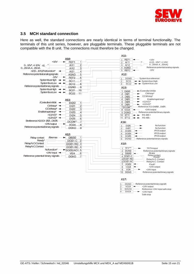
3.5 MCH standard connection Here as well, the standard connections are nearly identical in terms of terminal functionality. The terminals of this unit series, however, are pluggable terminals. These pluggable terminals are not compatible with the B unit. The connections must therefore be changed.
-10V
+10Vn1 (0...10V*; +/-10V;0...20mA; 4...20mA)
X11:12345
Reference potential analog signals
Reference potential binary signals
Reference potential binary signals+24V input
TF/TH input
Relay contactReady*
Relay N.C. ContactRelay N.O. Contact
/Brake
/Fault*+24V output
X10:
n11/n21*n12/n22*
RS-485 -RS-485 +
Reference potential binary signals
Enable/rapid stop*
/Controller inhibitCW/stop*
CCW/stop*
Reference X13:DIêê ...DIê5+24V output
X13:
X12:DGNDSC11SC12
123
System bus referenceSystem bus HighSystem bus Low
X16:DI 6DI 7DOê3DOê4DOê5DGND
êê
123456 Reference potential binary signals
No functionNo function
IPOS outputIPOS outputIPOS output
X17:DGNDVO24
SOV24SVI24
1234
Reference potential binary signals+24V outputReference +24V input safe stop+24V inputSafe stop
X10:
X11:
X12:
n11/n21*n12/n22*
-10V
+10V+-
0...10V*, +/-10V,0...20mA, 4...20mA
n1
Reference potential analog signals
Enable/rapid stop*
/Controller inhibit
n2 (0...10 V) /No function*
CW/stop*CCW/stop*
Breference X10:DI êê...DIê5
Reference potential binary signals
Reference potential binary signals
Reference potential binary signals+24V input
Relay contactReady*
Relay N.C. ContactRelay N.O. Contact
/Bremse
No function*
+24V output
System bus Low
System bus Low
System bus High
System bus High
GE-ATS/ Keller / Schneeloch / Ad_02046 Umstellungshilfe MCX und MDX_A auf MDX60/61B Seite 16 von 21
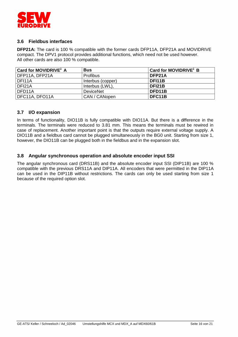
3.6 Fieldbus interfaces DFP21A: The card is 100 % compatible with the former cards DFP11A, DFP21A and MOVIDRIVE compact. The DPV1 protocol provides additional functions, which need not be used however. All other cards are also 100 % compatible. Card for MOVIDRIVE A Bus Card for MOVIDRIVE B DFP11A, DFP21A Profibus DFP21A DFI11A Interbus (copper) DFI11B DFI21A Interbus (LWL), DFI21B DFD11A DeviceNet DFD11B DFC11A, DFO11A CAN / CANopen DFC11B 3.7 I/O expansion In terms of functionality, DIO11B is fully compatible with DIO11A. But there is a difference in the terminals. The terminals were reduced to 3.81 mm. This means the terminals must be rewired in case of replacement. Another important point is that the outputs require external voltage supply. A DIO11B and a fieldbus card cannot be plugged simultaneously in the BG0 unit. Starting from size 1, however, the DIO11B can be plugged both in the fieldbus and in the expansion slot. 3.8 Angular synchronous operation and absolute encoder input SSI The angular synchronous card (DRS11B) and the absolute encoder input SSI (DIP11B) are 100 % compatible with the previous DRS11A and DIP11A. All encoders that were permitted in the DIP11A can be used in the DIP11B without restrictions. The cards can only be used starting from size 1 because of the required option slot.
GE-ATS / Keller / Schneeloch / Ad_02046 Umstellungshilfe MCX und MDX_A auf MDX60/61B Seite 17 von 21
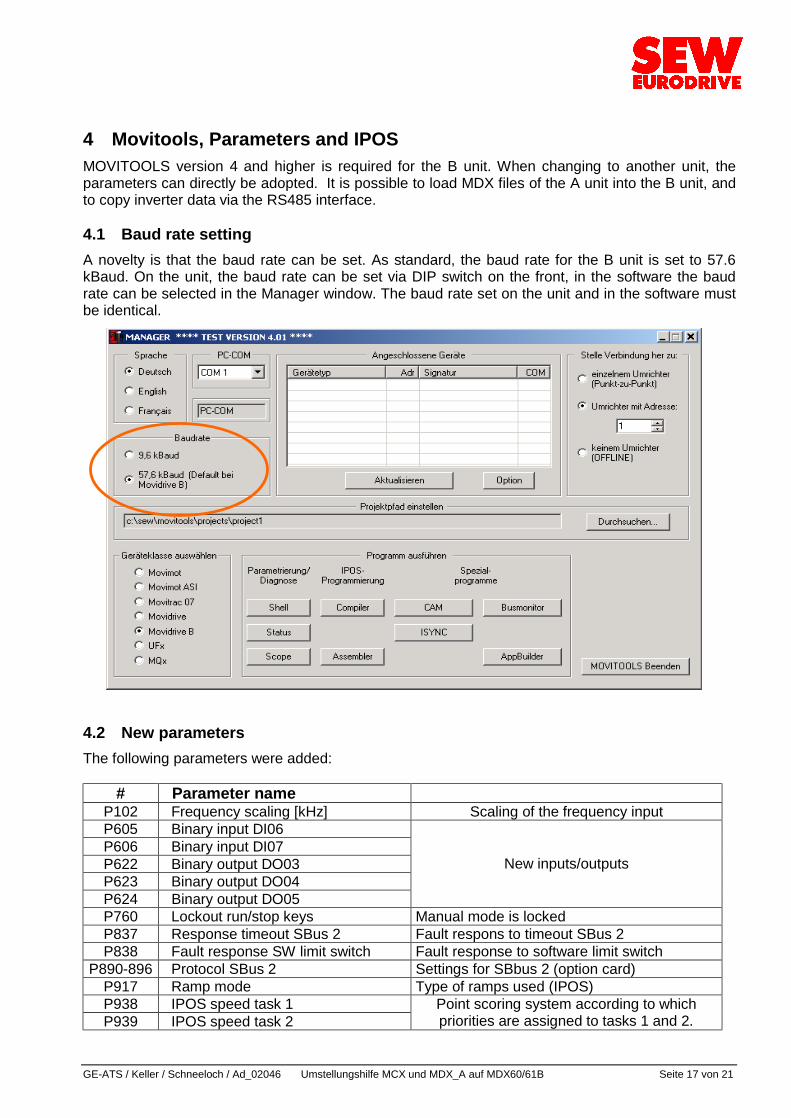
4 Movitools, Parameters and IPOS MOVITOOLS version 4 and higher is required for the B unit. When changing to another unit, the parameters can directly be adopted. It is possible to load MDX files of the A unit into the B unit, and to copy inverter data via the RS485 interface. 4.1 Baud rate setting A novelty is that the baud rate can be set. As standard, the baud rate for the B unit is set to 57.6 kBaud. On the unit, the baud rate can be set via DIP switch on the front, in the software the baud rate can be selected in the Manager window. The baud rate set on the unit and in the software must be identical.
4.2 New parameters The following parameters were added:
# Parameter name P102 Frequency scaling [kHz] Scaling of the frequency input P605 Binary input DI06 P606 Binary input DI07 P622 Binary output DO03 P623 Binary output DO04 P624 Binary output DO05
New inputs/outputs
P760 Lockout run/stop keys Manual mode is locked P837 Response timeout SBus 2 Fault respons to timeout SBus 2 P838 Fault response SW limit switch Fault response to software limit switch
P890-896 Protocol SBus 2 Settings for SBbus 2 (option card) P917 Ramp mode Type of ramps used (IPOS) P938 IPOS speed task 1 P939 IPOS speed task 2
Point scoring system according to which priorities are assigned to tasks 1 and 2.
GE-ATS/ Keller / Schneeloch / Ad_02046 Umstellungshilfe MCX und MDX_A auf MDX60/61B Seite 18 von 21
4.3 Modified parameters Some parameter blocks were modified or their position was altered to comply with the expanded functionality.
Old # New # Parameter name P160-P162 P170-P172
Changed layout, functionality remains the same.
P813 P881,P891 Address SBus 1,2 P814 P882,P892 Group address SBus 1,2 P815 P883,P893 Timeout time SBus 1,2 P816 P884,P894 Baud rate SBus 1,2 P817 P885,P895 Synchronization ID SBus 1,2 P818 P886,P896 CAN synchronization 1,2 P836 P836,P837 Response timeout SBus 1,2
4.4 Deleted parameters: In Movitools version 3.0, it was possible to make a selection in these parameters. This selection did not have any effect, however. These parameters are not required anymore because /Controller inhibit or brake will be assigned to input DI00 and output DO00.
# Parameter name Parameter name P608 Binary input DI00 Binary input DI00 P628 Binary output DO00 Binary output DO00
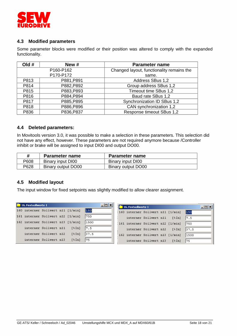
4.5 Modified layout The input window for fixed setpoints was slightly modified to allow clearer assignment.
GE-ATS / Keller / Schneeloch / Ad_02046 Umstellungshilfe MCX und MDX_A auf MDX60/61B Seite 19 von 21
4.6 IPOS Programs from the A unit can be directly adopted. But to achieve full compatibility, the speed of tasks 1 and 2 must not be increased. The most important novelty in IPOS programming is the additional task 3, which offers new options for IPOS programming. It is important that task 3 does not have a fixed time sharing division but is dependent on the utilization of tasks 1 and 2. But at least one instruction/ms will be interpreted. With the B unit, the setpoint access takes only 1 ms (instead of 5 ms). IPOS speed P938/P939: The speeds of tasks 1 and 2 can be set using these parameters. Task 1 obtains at least one point, task 2 at least two points (factory setting, corresponds with MDx/MCx). With each additional point, the respective task obtains one more instruction/ms. Nine additional points are set using the parameters. The points are added to the standard values (1 and 2). With this setting, task 1 has highest priority, the priority of task 2 is lowered automatically. 4.7 Application modules All application modules of MOVIDRIVE A and MOVIDRIVE compact are compatible with the B unit! The application modules ”Bus positioningß, ”Expanded bus positioningß and ”Table positioningß were revised and now feature improved performance. Additionally, there is the new application module ”Remaining distance positioning.ß The application module ”Rotary axisß and ”Crane controlß will not be available anymore starting from MOVITOOLS 4.0. These modules can be obtained from the A-Shell if they are still required. The new application module ”Modulo positioningß is the replacement for the ”Rotary axisß module. 4.8 Communication via SBus Communication via SBus for MOVIDRIVE and MOVIDRIVE compact is set in parameters P813 to P817. With MOVIDRIVE B, two sets are available in parameters P880 to P885. The first SBus parameter set is assigned to the basic unit. With the second parameter set, a second SBus is provided through the option card DFC. No problems occur when an MCH in conjunction with an SBus is replaced by an MDX61B. As the clock of the MDX60B/MDX61B is 40 kHz but that of the MCH is 25 kHz, they are not compatible when 1 MBaud is used. This incompatibility applies to the MCH only. All other units are compatible with each other. Compatibility can be restored by decreasing the transmission speed to 0.5 Mbaud. This restriction does not apply when all MCH are replaced by MDX61B because then all units are compatible.
GE-ATS/ Keller / Schneeloch / Ad_02046 Umstellungshilfe MCX und MDX_A auf MDX60/61B Seite 20 von 21
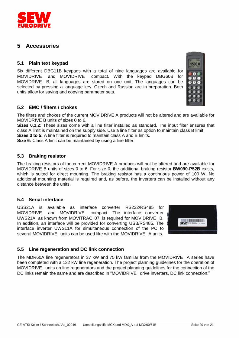
5 Accessories 5.1 Plain text keypad Six different DBG11B keypads with a total of nine languages are available for MOVIDRIVE and MOVIDRIVE compact. With the keypad DBG60B for MOVIDRIVE B, all languages are stored on one unit. The languages can be selected by pressing a language key. Czech and Russian are in preparation. Both units allow for saving and copying parameter sets. 5.2 EMC / filters / chokes The filters and chokes of the current MOVIDRIVE A products will not be altered and are available for MOVIDRIVE B units of sizes 0 to 6. Sizes 0,1,2: These sizes come with a line filter installed as standard. The input filter ensures that class A limit is maintained on the supply side. Use a line filter as option to maintain class B limit. Sizes 3 to 5: A line filter is required to maintain class A and B limits. Size 6: Class A limit can be maintained by using a line filter. 5.3 Braking resistor The braking resistors of the current MOVIDRIVE A products will not be altered and are available for MOVIDRIVE B units of sizes 0 to 6. For size 0, the additional braking resistor BW090-P52B exists, which is suited for direct mounting. The braking resistor has a continuous power of 100 W. No additional mounting material is required and, as before, the inverters can be installed without any distance between the units. 5.4 Serial interface USS21A is available as interface converter RS232/RS485 for MOVIDRIVE and MOVIDRIVE compact. The interface converter UWS21A, as known from MOVITRAC07, is required for MOVIDRIVE B. In addition, an interface will be provided for converting USB/RS485. The interface inverter UWS11A for simultaneous connection of the PC to several MOVIDRIVE units can be used like with the MOVIDRIVE A units. 5.5 Line regeneration and DC link connection The MDR60A line regenerators in 37 kW and 75 kW familiar from the MOVIDRIVE A series have been completed with a 132 kW line regeneration. The project planning guidelines for the operation of MOVIDRIVE units on line regenerators and the project planning guidelines for the connection of the DC links remain the same and are described in ”MOVIDRIVE drive inverters, DC link connection.ß

GE-ATS / Keller / Schneeloch / Ad_02046 Umstellungshilfe MCX und MDX_A auf MDX60/61B Seite 21 von 21
6 Summary The MOVIDRIVE B unit is highly compatible with its predecessors MOVIDRIVE A and MOVIDRIVE compact. When changing to MOVIDRIVE B, it is important to take into account the different dimensions and in some cases the different encoder plugs. For the latter, SEW-EURODRIVE offers adapters for fast and fault-free exchange. MOVITOOLS software version 4.0 and higher and the UWS21A interface are required for connection to the PC. In most cases, the accessories can still be used. Programming and application modules also run in the B unit.