Embed Size (px)
Citation preview
M O T O R E N K A T A L O G m o t o r c a t a l o g u e
2
R O S Y N C
ROBASE R O S L Y D E
M O T O R S E R I E m o t o r s e r i e s
36 M O T O R T Y P m o t o r t y p e
2S P A N N U N G
v o l t a g e
GG E T R I E B E T Y P
g e a r t y p e
•
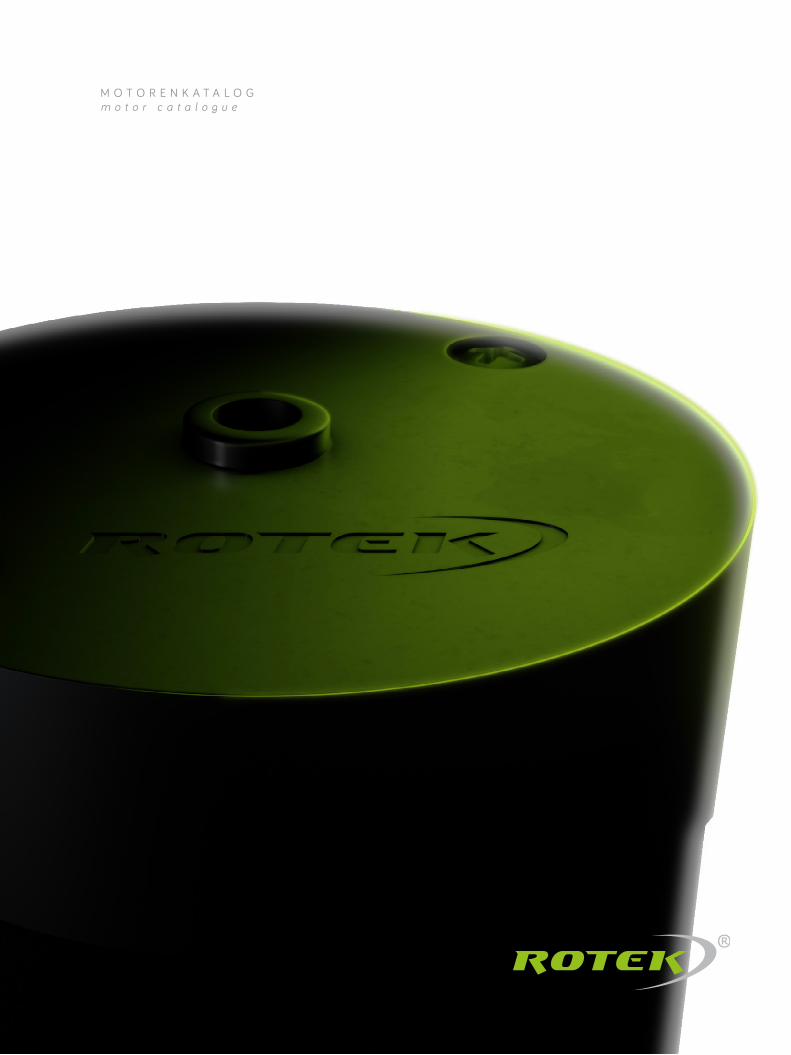
Mit dem R O T E K -Baukastensystem machen wir Millionen individueller Lösungen möglich – seit fast 30 Jahren und auch in kleinen Serien. Sie bekommen genau den Motor, den Sie für Ihre Anwendung brauchen. Wir setzen auf firmeneigene Entwicklungen, langjährig zuverlässige Lie-feranten und eine hohe Fertigungstiefe. So gewährleisten
P E R F E K T E S Z U S A M M E N S P I E L – H O H E F L E X I B I L I T Ä T Per fect in teract ion – great f lex ib i l i ty
S P A N N U N G vol tage
0 = 1 ~ 24 V1 = 1 ~ 115 V 2 = 1 ~ 230 V3 = 3 ~ 230 V4 = 3 ~ 400 VX = Sonderwicklung special windings
G E T R I E B E T Y P gear type
S T I R N R A D G E T R I E B E spur gear
G = 6 NmV = 8 Nm (Welle 10 mm) (shaft 10 mm) W = 8 Nm (Welle 12 mm) (shaft 12 mm)
S C H N E C K E N G E T R I E B E worm gear
S = 5-12 Nm
P L A N E T E N G E T R I E B E planetary gear
Q = Ø 42 mmP = Ø 52 mm R = Ø 62 mm
F L A C H G E T R I E B E f la t gear
A = 10 NmB = 20 Nm C = 27 Nm
wir die Verwendung sehr hochwertiger Materialien, beste Verarbeitung und bestens durchdachte Konstruktionen – auch im Detail. Ein geringer Energieverbrauch, der spar- same Einsatz von Material und die lange Haltbarkeit der R O T E K -Motoren sind unser Beitrag für nachhaltiges Wirtschaften und eine saubere Umwelt.
T Y P E N S C H L Ü S S E L ( B E S T E L L B E I S P I E L ) type code (example for ordering)
3
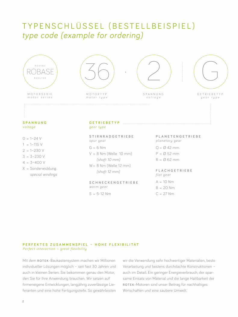
125 Ü B E R S E T Z U N G
r a t i o
B XO P T I O N E N ( A L P H A B E T I S C H )
o p t i o n s ( a l p h a b e t i c a l )
RA B T R I E B S W E L L E
o u t p u t s h a f t
•
With the R O T E K modular system we make millions of individual solutions possible. We have been doing so for almost 30 years, including in small series. That means you get precisely the motor you need for your application. We focus on our own developments, using reliable long-term suppliers and in-depth manufacturing
processes. That way we can guarantee well-thought-out designs using premium materials and outstanding workmanship down to the last detail. Our low power consumption, sparing use of materials and great dura-bility of R O T E K motors represent our contribution to the sustainable use of resources and a cleaner environment.
A B T R I E B S W E L L E output shaf t
R = rund roundF = abgeflacht flat P = Passfeder feather key S = Scheibenfeder woodruff key H = Hohlwelle hollow shaft X = kundenspezifische Welle customized shaft
Zusatz für Schneckengetriebe addition for worm gearboxes
B = beidseitig both sides L = links left R = rechts right
O P T I O N E N opt ions
B = Bremse brake E = Impulsgeber encoder H = verstärktes Selbsthaltemoment improved self-holding torqueI = IP55 (Planetengetriebe IP53) IP55 (planetary gearbox IP53) K = Klemmkasten terminal box L = Low-Noise-Getriebe low-noise gearbox S = Kurzzeitbetrieb short-time operation T = Thermoschutz thermal protection X = kundenspezif. Ausführung customized version
4
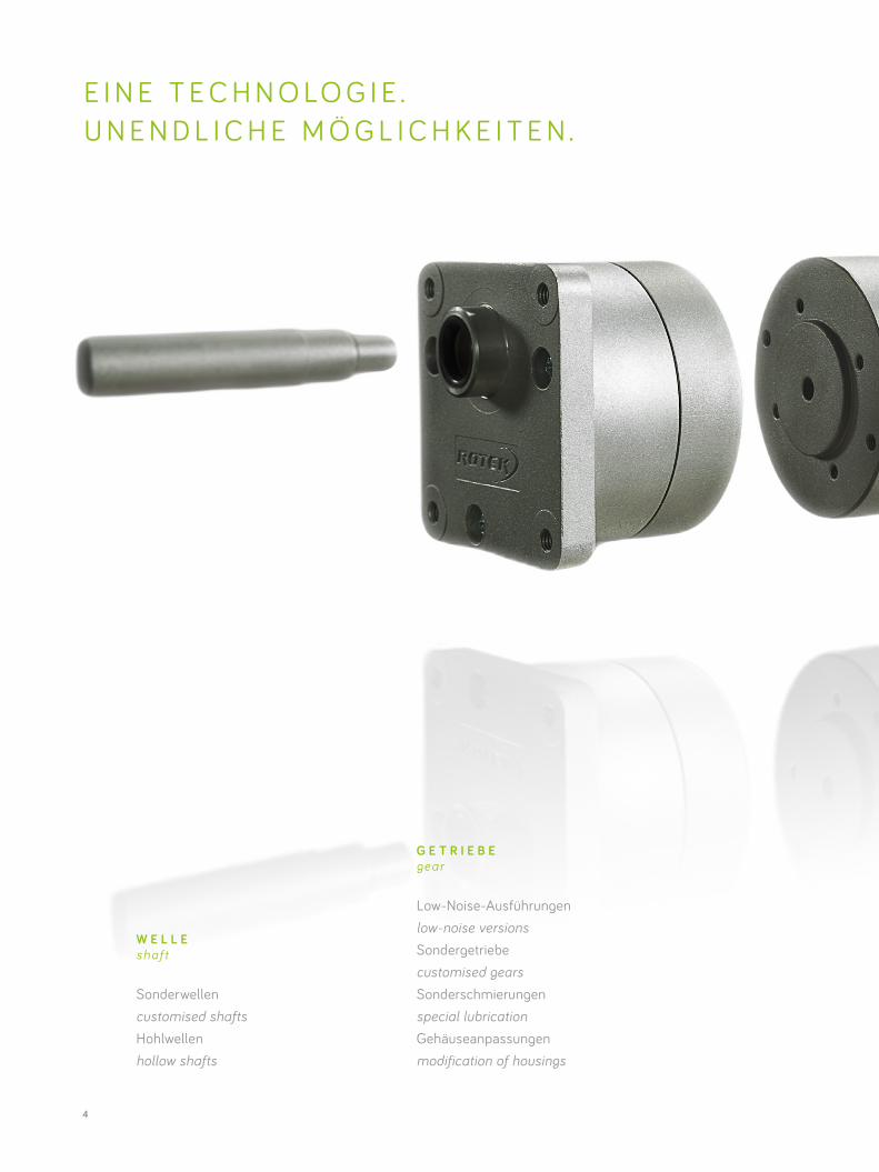
E I N E T E C H N O LO G I E .U N E N D L I C H E M Ö G L I C H K E I T E N .
G E T R I E B E gear
Low-Noise-Ausführungen low-noise versions Sondergetriebe customised gearsSonderschmierungen special lubrication Gehäuseanpassungen modification of housings
W E L L E shaft
Sonderwellen customised shaftsHohlwellen hollow shafts
5
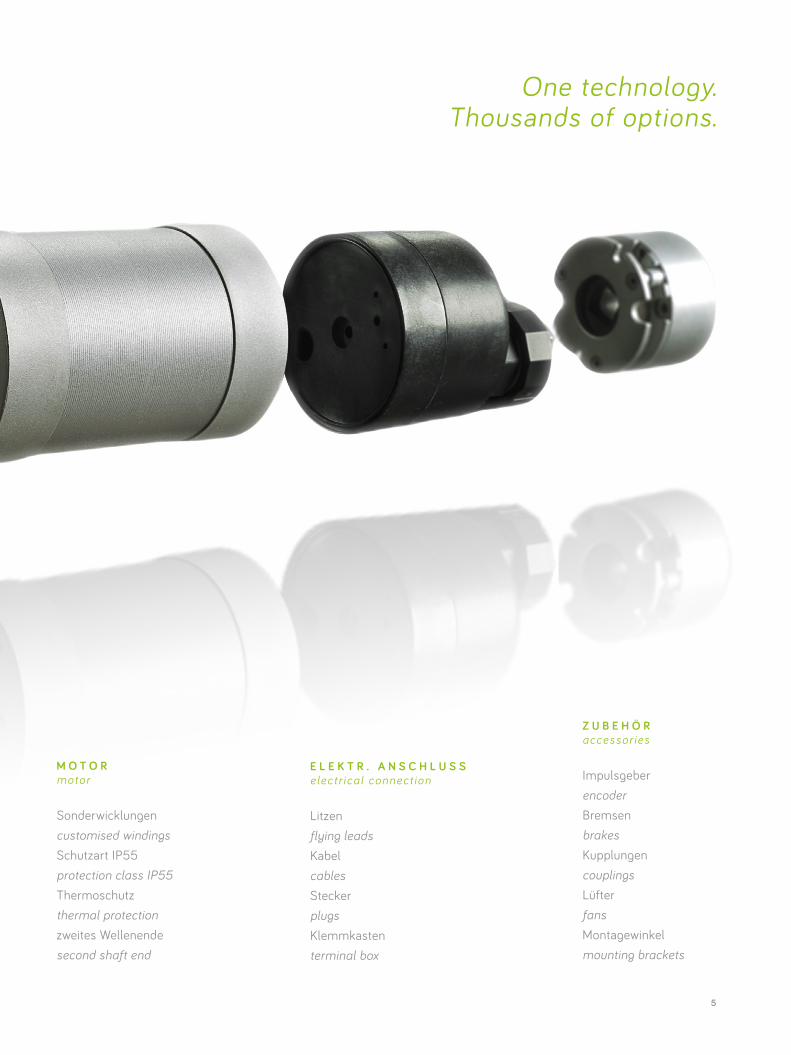
One technology. Thousands of options.
M O T O R motor
Sonderwicklungen customised windingsSchutzart IP55 protection class IP55Thermoschutz thermal protection zweites Wellenende second shaft end
Z U B E H Ö R accessor ies
Impulsgeber encoderBremsen brakesKupplungen couplingsLüfter fansMontagewinkel mounting brackets
E L E K T R . A N S C H L U S S elect r ica l connect ion
Litzen flying leadsKabel cablesStecker plugsKlemmkasten terminal box
6
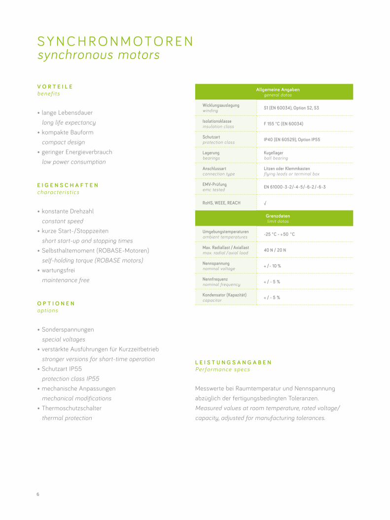
Allgemeine Angabengeneral datas
Wicklungsauslegung winding S1 (EN 60034), Option S2, S3
Isolationsklasse insulation class F 155 °C (EN 60034)
Schutzart protection class IP40 (EN 60529), Option IP55
Lagerung bearings
Kugellager ball bearing
Anschlussart connection type
Litzen oder Klemmkasten flying leads or terminal box
EMV-Prüfung emc tested EN 61000-3-2/-4-5/-6-2 /-6-3
RoHS, WEEE, REACH √
Grenzdaten limit datas
Umgebungstemperaturen ambient temperatures -25 ° C - + 50 ° C
Max. Radiallast / Axiallast max. radial / axial load 40 N / 20 N
Nennspannung nominal voltage + / - 10 %
Nennfrequenz nominal frequency + / - 5 %
Kondensator (Kapazität) capacitor + / - 5 %
V O R T E I L E benef i ts
• lange Lebensdauer long life expectancy• kompakte Bauform compact design• geringer Energieverbrauch low power consumption
E I G E N S C H A F T E N character is t ics
• konstante Drehzahl constant speed• kurze Start-/Stoppzeiten short start-up and stopping times• Selbsthaltemoment (ROBASE-Motoren) self-holding torque (ROBASE motors)• wartungsfrei maintenance free
O P T I O N E N opt ions
• Sonderspannungen special voltages• verstärkte Ausführungen für Kurzzeitbetrieb stronger versions for short-time operation• Schutzart IP55 protection class IP55• mechanische Anpassungen mechanical modifications• Thermoschutzschalter thermal protection
S Y N C H R O N M O T O R E N synchronous motors
L E I S T U N G S A N G A B E NPer formance specs
Messwerte bei Raumtemperatur und Nennspannung abzüglich der fertigungsbedingten Toleranzen.Measured values at room temperature, rated voltage/ capacity, adjusted for manufacturing tolerances.
7
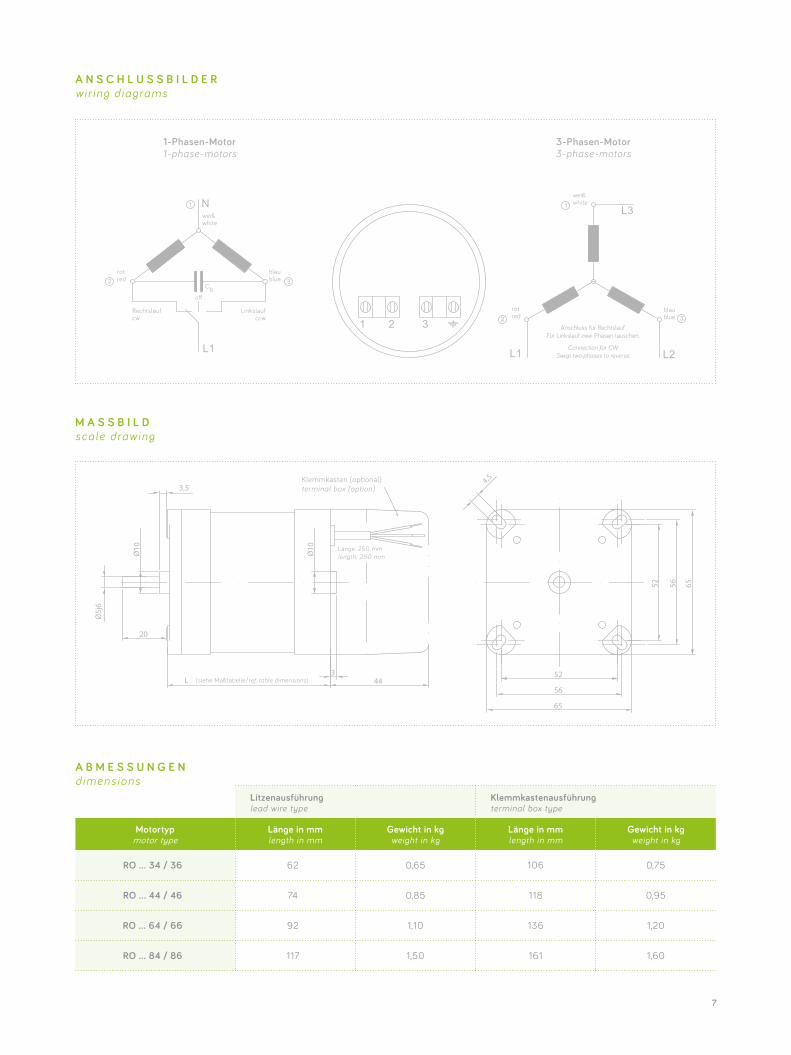
Litzenausführung lead wire type
Klemmkastenausführung terminal box type
Motortyp motor type
Länge in mm length in mm
Gewicht in kg weight in kg
Länge in mm length in mm
Gewicht in kg weight in kg
RO … 34 / 36 62 0,65 106 0,75
RO … 44 / 46 74 0,85 118 0,95
RO … 64 / 66 92 1,10 136 1,20
RO … 84 / 86 117 1,50 161 1,60
M A S S B I L D scale drawing
A N S C H L U S S B I L D E R wir ing d iagrams
A B M E S S U N G E N dimens ions
Klemmkasten (optional) terminal box (option)
length: 250 mm
(siehe Maßtabelle/ref. table dimensions)
1-Phasen-Motor 1-phase-motors
weiß white
rot red
blau blue
3-Phasen-Motor 3-phase-motors
weiß white
rot red
blau blue
o�
Linkslauf ccw
Rechtslauf cw
Cb
Anschluss für Rechtslauf.Für Linkslauf zwei Phasen tauschen.
Connection for CW.Swap two phases to reverse.
8
60
70
80
9 0
50
100
110
0 15 30 45 60 75 90 105 120
Wicklungsübertemperatur / K winding over temperature/K
Drehmoment torque
60
80
100
1 2 0
40
140
160
80 %
Drehmoment torque
Nennspannung nominal voltage
90 % 100 % 110 %
Leistungpower
Selbsthaltemomentholding torque
Laufruhesmoothness
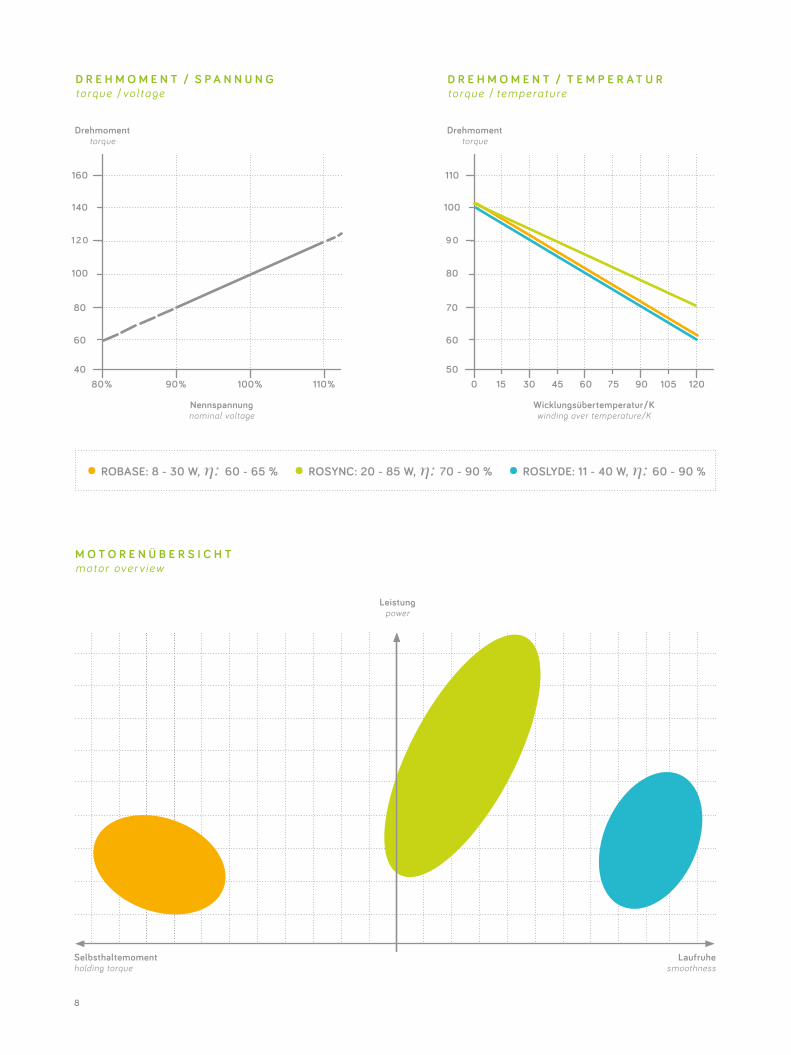
D R E H M O M E N T / S P A N N U N G torque /vol tage
D R E H M O M E N T / T E M P E R A T U R torque / t emperature
M O T O R E N Ü B E R S I C H T motor over v iew
• ROBASE: 8 - 30 W, η: 60 - 65 % • ROSYNC: 20 - 85 W, η: 70 - 90 % • ROSLYDE: 11 - 40 W, η: 60 - 90 %
9
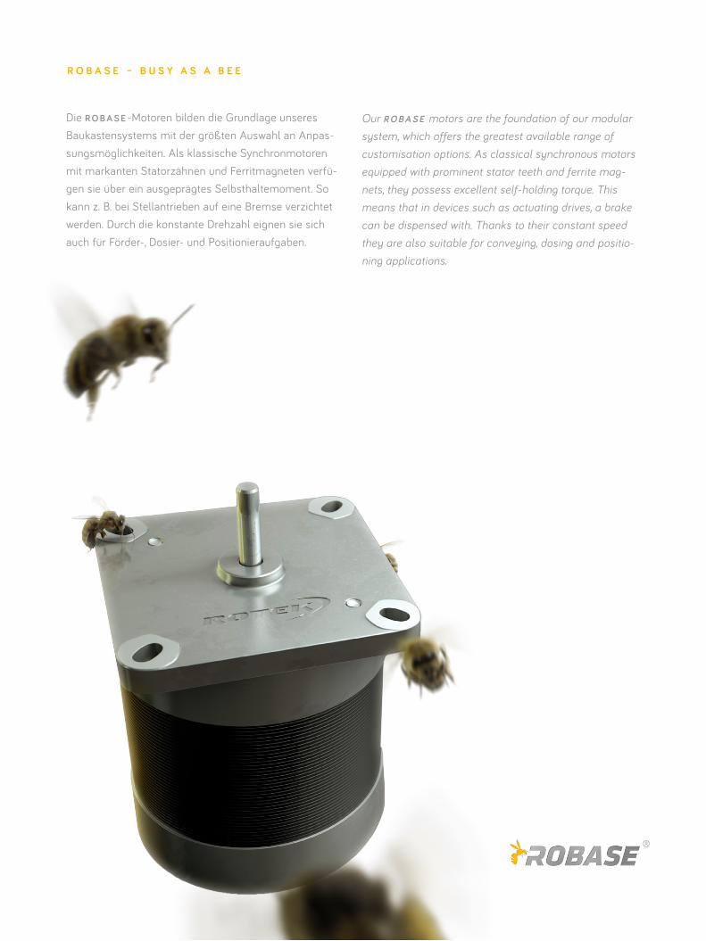
Die R O B A S E -Motoren bilden die Grundlage unseres Baukastensystems mit der größten Auswahl an Anpas-sungsmöglichkeiten. Als klassische Synchronmotoren mit markanten Statorzähnen und Ferritmagneten verfü-gen sie über ein ausgeprägtes Selbsthaltemoment. So kann z. B. bei Stellantrieben auf eine Bremse verzichtet werden. Durch die konstante Drehzahl eignen sie sich auch für Förder-, Dosier- und Positionieraufgaben.
Our R O B A S E motors are the foundation of our modular system, which offers the greatest available range of customisation options. As classical synchronous motors equipped with prominent stator teeth and ferrite mag-nets, they possess excellent self-holding torque. This means that in devices such as actuating drives, a brake can be dispensed with. Thanks to their constant speed they are also suitable for conveying, dosing and positio-ning applications.
R O B A S E – B U S Y A S A B E E
10
Spannungvoltage
Frequenzfrequency
Drehzahlspeed
Konden-sator
capacitor
Nennstromrated current
Aufnahme- leistung
input power
Dreh- moment
torque
Abgabe- leistung
output power
Wicklungs- über-
temperaturwinding over temperature
Selbsthalte- moment
self-holding torque
V Hz 1/min µ F mA VA Ncm W K Ncm
Motortyp 36 motor type 36
3~400
50/60 1000/1200
- 60/55 24/22 10,5/7,0 11,0/9,0
85 0,9
3~230* - 100/80 23/18 10/6,0 10,5/7,5
1~230 0,5 80/85
18/19 7,5/6,5 8,01~115 2 160/170
1~24 42 750/780
Motortyp 46 motor type 46
3~400
50/60 1000/1200
- 105/85 42/35 14,0/10,0 15,0/13,0
85 1,3
3~230* - 150/130 35/30 13,0/9,0 14,0/12,0
1~230 0,68 105/115
24/26 11,0/9,0 11,51~115 2,8 210/230
1~24 60 1000/1100
Motortyp 66 motor type 66
3~400
50/60 1000/1200
- 120/100 48/4019,0/14,0 20,0/17,0
105 1,8
3~230* - 220/180 50/40
1~230 1 150/160
34/37 15,0/13,0 16,01~115 4 300/320
1~24 90 1400/1550
Motortyp 86 motor type 86
3~400
50/60 1000/1200
- 170/140 68/56 28,0/18,0 29,0/23,085
2,6
3~230* - 300/240 70/55 25,0/16,0 26,0/20,0
1~230 1,3 190/200
44/46 21,0/18,0 22,0 1051~115 5 380/400
1~24 120 1710/1800
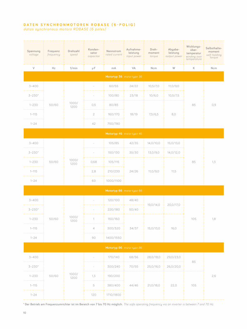
D A T E N S Y N C H R O N M O T O R E N R O B A S E ( 6 - P O L I G )datas synchronous motors ROBASE (6 poles)
* Der Betrieb am Frequenzumrichter ist im Bereich von 7 bis 70 Hz möglich. The safe operating frequency via an inverter is between 7 and 70 Hz.
11
Spannungvoltage
Frequenzfrequency
Drehzahlspeed
Konden-sator
capacitor
Nennstromrated current
Aufnahme- leistung
input power
Dreh- moment
torque
Abgabe- leistung
output power
Wicklungs- über-
temperaturwinding over temperature
Selbsthalte- moment
self-holding torque
V Hz 1/min µ F mA VA Ncm W K Ncm
Motortyp 34 motor type 34
3~400
50/60 1500/ 1800
- 50/45 20/187,0/5,0 11,0/9,0
85 3,0
3~230* - 100/80 23/18
1~230 0,5 75/80
17/18 6,0/5,0 9,01~115 2 150/160
1~24 42 710/750
Motortyp 44 motor type 44
3~400
50/60 1500/ 1800
- 90/75 36/3010,0/7,0 15,0/13,0 85
4,2
3~230* - 150/130 35/30
1~230 0,68 105/115
24/26 9,0/7,5 14,0 1051~115 2,8 210/230
1~24 60 1000/1100
Motortyp 64 motor type 64
3~400
50/60 1500/ 1800
- 105/90 42/3613,0/9,0 20,0/17,0
85
6,0
3~230* - 220/180 50/40
1051~230 1 150/160
34/37 12,0/10,0 19,01~115 4 300/320
1~24 90 1400/1550
Motortyp 84 motor type 84
3~400
50/60 1500/ 1800
- 150/120 60/48 18,0/12,0 28,0/23,085
8,5
3~230* - 300/240 70/55 20,0/14,0 31,0/26,0
1~230 1,3 205/220
47/51 18,0/15,0 28,0 1051~115 5 410/440
1~24 120 1960/2100
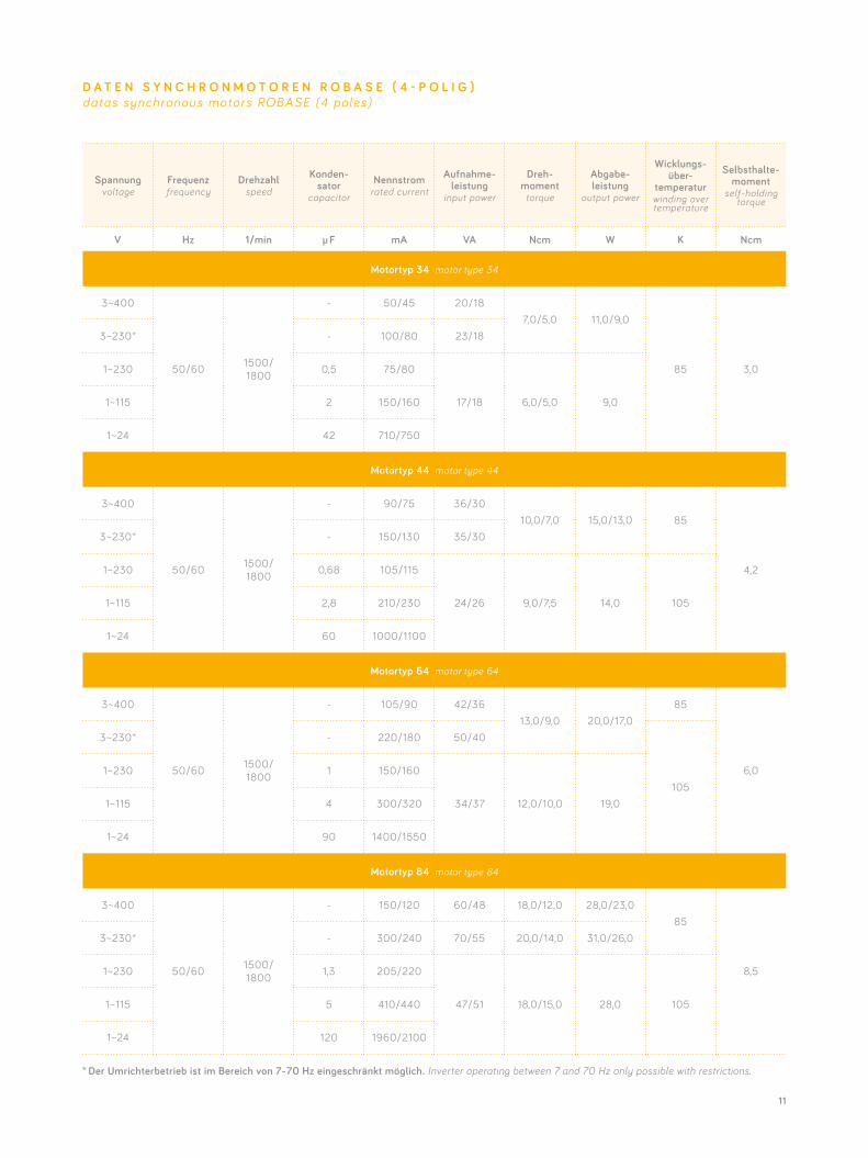
D A T E N S Y N C H R O N M O T O R E N R O B A S E ( 4 - P O L I G )datas synchronous motors ROBASE (4 poles)
* Der Umrichterbetrieb ist im Bereich von 7-70 Hz eingeschränkt möglich. Inverter operating between 7 and 70 Hz only possible with restrictions.
12
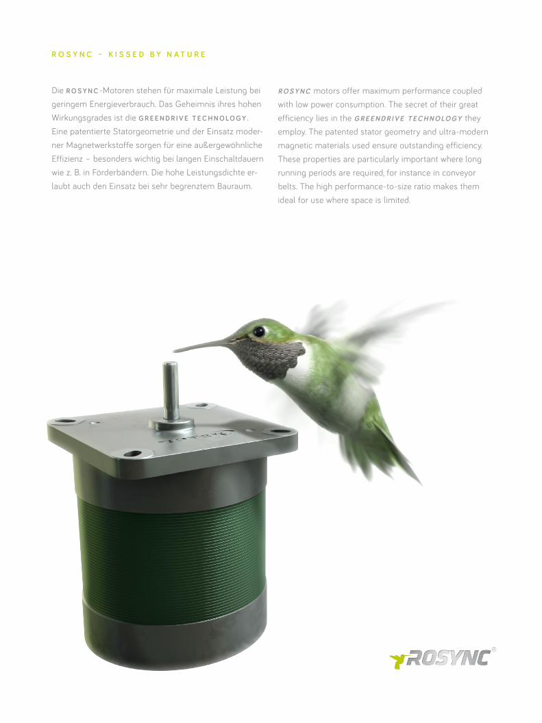
Die R O S Y N C -Motoren stehen für maximale Leistung bei geringem Energieverbrauch. Das Geheimnis ihres hohen Wirkungsgrades ist die G R E E N D R I V E T E C H N O LO G Y . Eine patentierte Statorgeometrie und der Einsatz moder-ner Magnetwerkstoffe sorgen für eine außergewöhnliche Effizienz – besonders wichtig bei langen Einschaltdauern wie z. B. in Förderbändern. Die hohe Leistungsdichte er- laubt auch den Einsatz bei sehr begrenztem Bauraum.
R O S Y N C motors offer maximum performance coupled with low power consumption. The secret of their great efficiency lies in the G R E E N D R I V E T E C H N O LO G Y they employ. The patented stator geometry and ultra-modern magnetic materials used ensure outstanding efficiency. These properties are particularly important where long running periods are required, for instance in conveyor belts. The high performance-to-size ratio makes them ideal for use where space is limited.
R O S Y N C – K I S S E D B Y N A T U R E
13
Spannungvoltage
Frequenzfrequency
Drehzahlspeed
Kondensatorcapacitor
Nennstromrated current
Aufnahme- leistung
input power
Drehmomenttorque
Abgabe- leistung
output power
Wicklungs- über-
temperaturwinding over temperature
V Hz 1/min µ F mA VA Ncm W K
Motortyp 44 motor type 44
3~400
50/60 1500/1800
- 100/8570/60 32/25 50/47 85
3~230* - 175/150
1~230** 1,3 130/135
30/31 13/12 20/22 105 1~115** 5,2 260/270
1~24** 120 1250/1300
Spannungvoltage
Frequenzfrequency
Drehzahlspeed
Kondensatorcapacitor
Nennstromrated current
Aufnahme- leistung
input power
Drehmomenttorque
Abgabe- leistung
output power
Wicklungs- über-
temperaturwinding over temperature
V Hz 1/min µ F mA VA Ncm W K
Motortyp 84 motor type 84
3~400
50/60 1500/1800
- 200/175140/120 54/38 85/72 85
3~230* - 350/300
1~230** 2,0 220/240
51/55 23/21 36/40 105 1~115** 8,0 440/480
1~24** 180 2100/2300
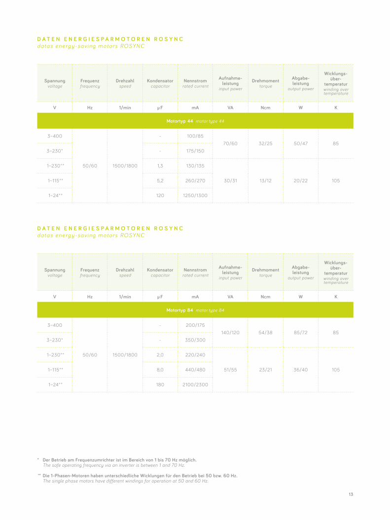
D A T E N E N E R G I E S P A R M O T O R E N R O S Y N Cdatas energ y-sav ing motors ROSYNC
* Der Betrieb am Frequenzumrichter ist im Bereich von 1 bis 70 Hz möglich. The safe operating frequency via an inverter is between 1 and 70 Hz.
** Die 1-Phasen-Motoren haben unterschiedliche Wicklungen für den Betrieb bei 50 bzw. 60 Hz. The single phase motors have different windings for operation at 50 and 60 Hz.
D A T E N E N E R G I E S P A R M O T O R E N R O S Y N Cdatas energ y-sav ing motors ROSYNC
14
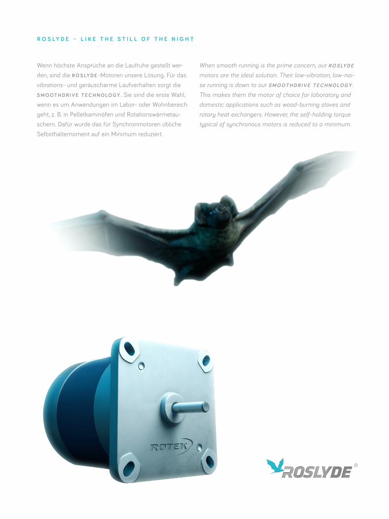
Wenn höchste Ansprüche an die Laufruhe gestellt wer-den, sind die R O S LY D E -Motoren unsere Lösung. Für das vibrations- und geräuscharme Laufverhalten sorgt die S M O O T H D R I V E T E C H N O LO G Y . Sie sind die erste Wahl, wenn es um Anwendungen im Labor- oder Wohnbereich geht, z. B. in Pelletkaminöfen und Rotationswärmetau-schern. Dafür wurde das für Synchronmotoren übliche Selbsthaltemoment auf ein Minimum reduziert.
R O S L Y D E – L I K E T H E S T I L L O F T H E N I G H T
When smooth running is the prime concern, our R O S LY D E motors are the ideal solution. Their low-vibration, low-noi-se running is down to our S M O O T H D R I V E T E C H N O LO G Y . This makes them the motor of choice for laboratory and domestic applications such as wood-burning stoves and rotary heat exchangers. However, the self-holding torque typical of synchronous motors is reduced to a minimum.
15
Spannungvoltage
Frequenzfrequency
Drehzahlspeed
Kondensatorcapacitor
Nennstromrated current
Aufnahme- leistung
input power
Drehmomenttorque
Abgabe- leistung
output power
Wicklungs- über-
temperaturwinding over temperature
V Hz 1/min µ F mA VA Ncm W K
Motortyp 44 motor type 44
3~400
50/60 1500/1800
- 55/43 38/3013/8,5 20/16 20
3~230* - 100/80 40/32
1~230** 0,68 75/70
17/16 7/6 11 501~115** 2,80 148/140
1~24** 60 710/670
Spannungvoltage
Frequenzfrequency
Drehzahlspeed
Kondensatorcapacitor
Nennstromrated current
Aufnahme- leistung
input power
Drehmomenttorque
Abgabe- leistung
output power
Wicklungs- über-
temperaturwinding over temperature
V Hz 1/min µ F mA VA Ncm W K
Motortyp 84 motor type 84
3~400
50/60 1500/1800
- 100/8370/57 26/17 40/32 20
3~230* - 175/143
1~230** 1,3 150/140
34,5/32 14/11,5 22 851~115** 5,2 300/280
1~24** 120 1440/1330
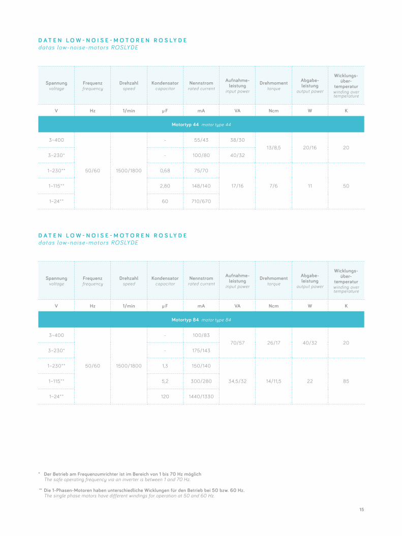
D A T E N L O W - N O I S E - M O T O R E N R O S L Y D Edatas low-noise-motors ROSLYDE
D A T E N L O W - N O I S E - M O T O R E N R O S L Y D Edatas low-noise-motors ROSLYDE
* Der Betrieb am Frequenzumrichter ist im Bereich von 1 bis 70 Hz möglich The safe operating frequency via an inverter is between 1 and 70 Hz.
** Die 1-Phasen-Motoren haben unterschiedliche Wicklungen für den Betrieb bei 50 bzw. 60 Hz. The single phase motors have different windings for operation at 50 and 60 Hz.
16
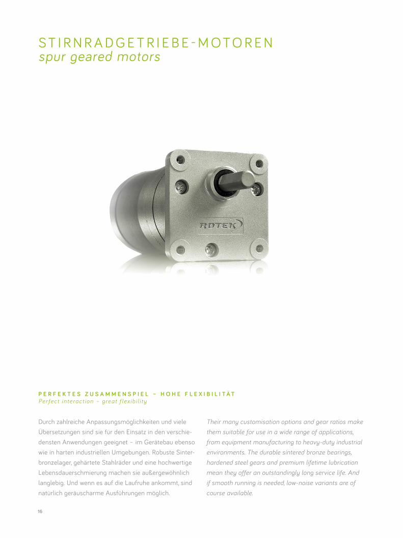
S T I R N R A D G E T R I E B E - M O T O R E N spur geared motors
Durch zahlreiche Anpassungsmöglichkeiten und viele Übersetzungen sind sie für den Einsatz in den verschie-densten Anwendungen geeignet – im Gerätebau ebenso wie in harten industriellen Umgebungen. Robuste Sinter-bronzelager, gehärtete Stahlräder und eine hochwertige Lebensdauerschmierung machen sie außergewöhnlich langlebig. Und wenn es auf die Laufruhe ankommt, sind natürlich geräuscharme Ausführungen möglich.
Their many customisation options and gear ratios make them suitable for use in a wide range of applications, from equipment manufacturing to heavy-duty industrial environments. The durable sintered bronze bearings, hardened steel gears and premium lifetime lubrication mean they offer an outstandingly long service life. And if smooth running is needed, low-noise variants are of course available.
P E R F E K T E S Z U S A M M E N S P I E L – H O H E F L E X I B I L I T Ä TPer fect in teract ion – great f lex ib i l i ty
17
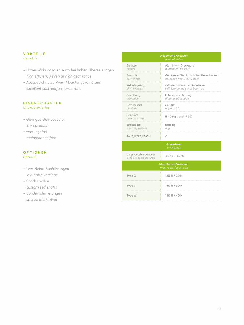
Allgemeine Angabengeneral datas
Gehäuse housing
Aluminium-Druckgussaluminium die-cast
Zahnräder gear wheels
Gehärteter Stahl mit hoher Belastbarkeit hardened heavy duty steel
Wellenlagerung shaft bearings
selbstschmierende Sinterlager self-lubricating sinter bearings
Schmierung lubrication
Lebensdauerfettunglifetime lubrication
Getriebespiel backlash
ca. 0,8°approx. 0.8
Schutzart protection class IP40 (optional IP55)
Einbaulagen assembly position
beliebigany
RoHS, WEEE, REACH √
Grenzdaten limit datas
Umgebungstemperaturen ambient temperatures -25 °C - +50 °C
Max. Radial-/Axiallastmax. radial /axial load
Type G 120 N / 20 N
Type V 150 N / 30 N
Type W 180 N / 40 N
V O R T E I L E benef i ts
• Hoher Wirkungsgrad auch bei hohen Übersetzungen high efficiency even at high gear ratios• Ausgezeichnetes Preis-/ Leistungsverhältnis excellent cost-performance ratio
E I G E N S C H A F T E N character is t ics
• Geringes Getriebespiel low backlash• wartungsfrei maintenance free
O P T I O N E N opt ions
• Low-Noise-Ausführungen low-noise versions• Sonderwellen customised shafts• Sonderschmierungen special lubrication
18
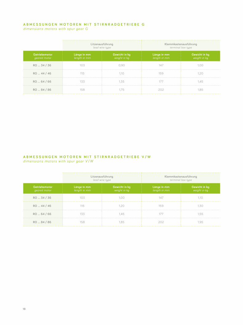
Litzenausführung lead wire type
Klemmkastenausführung terminal box type
Getriebemotorgeared motor
Länge in mm length in mm
Gewicht in kg weight in kg
Länge in mm length in mm
Gewicht in kg weight in kg
RO … 34 / 36 103 0,90 147 1,00
RO … 44 / 46 115 1,10 159 1,20
RO … 64 / 66 133 1,35 177 1,45
RO … 84 / 86 158 1,75 202 1,85
Litzenausführung lead wire type
Klemmkastenausführung terminal box type
Getriebemotorgeared motor
Länge in mm length in mm
Gewicht in kg weight in kg
Länge in mm length in mm
Gewicht in kg weight in kg
RO … 34 / 36 103 1,00 147 1,10
RO … 44 / 46 115 1,20 159 1,30
RO … 64 / 66 133 1,45 177 1,55
RO … 84 / 86 158 1,85 202 1,95
A B M E S S U N G E N M O T O R E N M I T S T I R N R A D G E T R I E B E G dimens ions motors wi th spur gear G
A B M E S S U N G E N M O T O R E N M I T S T I R N R A D G E T R I E B E V / W dimens ions motors wi th spur gear V /W
19
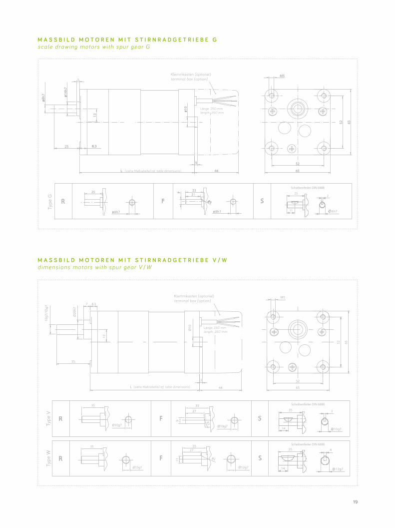
M A S S B I L D M O T O R E N M I T S T I R N R A D G E T R I E B E V / W dimens ions motors wi th spur gear V /W
M A S S B I L D M O T O R E N M I T S T I R N R A D G E T R I E B E G scale drawing motors wi th spur gear G
35
Ø12g7 Ø12g7
2735
11
R1
35
Ø10g7
27
9
35
R1
Ø10g7
6544
52
52 65
3
Ø10
M5
13
7
Ø20
h7
35
8,3
10g7
L
Klemmkasten (optional) terminal box (option)
Type
VTy
pe W
length: 250 mm
/12g
7
(siehe Maßtabelle/ref. table dimensions)
35
14
3
10 g7
Scheibenfeder DIN 6888
Scheibenfeder DIN 6888
14
35 4
12g7
length: 250 mm
Klemmkasten (optional) terminal box (option)
Type
G
(siehe Maßtabelle/ref. table dimensions)
Scheibenfeder DIN 6888
25
11
2
8 h7
20
Übersetzungratio
zulässiges Drehmoment (Spitze)permitted torque (peak)
Drehzahlspeed
Drehmoment der Motortypentorque of motor types
iType G Type V Type W
1/min36 46 66 86
Nm Nm Nm Nm Nm Nm Nm
2-stufig η = 81 % 2 stages η = 81 %
5 6 (10) - - 200 0,30 0,45 0,61 0,85
10 6 (10) - 8 (13) 100 0,61 0,89 1,22 1,70
13,3 6 (10) - - 75 0,81 1,19 1,62 2,26
16,6 6 (10) - - 60 1,01 1,48 2,02 2,82
20 6 (10) - - 50 1,22 1,78 2,43 3,40
3-stufig η = 73 % 3 stages η = 73 %
25 6 (10) - - 40 1,37 2,01 2,74 3,83
33,3 6 (10) 8 (13) - 30 1,82 2,67 3,65 5,10
50 6 (10) - 8 (13) 20 2,74 4,02 5,48 7,67
60 6 (10) - 8 (13) 16,6 3,29 4,82 6,57 9,20
66,6 6 (10) - - 15,0 3,65 5,35 7,29 10,21
4-stufig η = 66 % 4 stages η = 66 %
75 6 (10) - 8 (13) 13,3 3,71 5,45 7,43 10,40
100 6 (10) - 8 (13) 10 4,95 7,26 9,90 13,86
125 6 (10) 8 (13) 8 (13) 8 6,19 9,08 12,38 -
150 6 (10) - - 6,6 7,43 10,89 14,85 -
200 6 (10) - 8 (13) 5 9,90 14,52 - -
250 6 (10) 8 (13) 8 (13) 4 12,38 - - -
5-stufig η = 59 % 5 stages η = 59 %
500 6 (10) 8 (13) - 2 22,13 - - -
1000 6 (10) 8 (13) - 1 44,25 - - -
1333,3 6 (10) - - 0,75 59,00 - - -
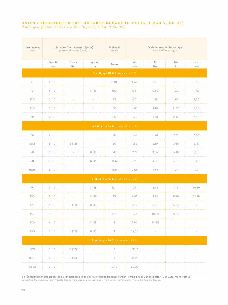
D A T E N S T I R N R A D G E T R I E B E – M O T O R E N R O B A S E ( 6 - P O L I G , 1 ~ 2 3 0 V , 5 0 H Z )datas spur geared motors ROBASE (6 poles , 1~230 V, 50 Hz)
Bei Überschreiten des zulässigen Drehmoments kann das Getriebe beschädigt werden. Three-phase variants offer 10 to 30% more torque. Exceeding the maximum permissible torque may lead to gear damage. Three-phase variants offer 10 to 30 % more torque.
21
Übersetzungratio
zulässiges Drehmoment (Spitze)permitted torque (peak)
Drehzahlspeed
Drehmoment der Motortypentorque of motor types
iType G Type V Type W
1/min34 44 64 84
Nm Nm Nm Nm Nm Nm Nm
2-stufig η = 81 % 2 stages η = 81 %
5 6 (10) - - 300 0,24 0,36 0,49 0,73
10 6 (10) - 8 (13) 150 0,49 0,73 0,97 1,46
13,3 6 (10) - - 112,5 0,65 0,97 1,29 1,94
16,6 6 (10) - - 90 0,81 1,21 1,61 2,42
20 6 (10) - - 75 0,97 1,46 1,94 2,92
3-stufig η = 73 % 3 stages η = 73 %
25 6 (10) - - 60 1,10 1,64 2,19 3,29
33,3 6 (10) 8 (13) - 45 1,46 2,19 2,92 4,38
50 6 (10) - 8 (13) 30 2,19 3,29 4,38 6,57
60 6 (10) - 8 (13) 25 2,63 3,94 5,26 7,88
66,6 6 (10) - - 22,5 2,92 4,38 5,83 8,75
4-stufig η = 66 % 4 stages η = 66 %
75 6 (10) - 8 (13) 20 2,97 4,46 5,94 8,91
100 6 (10) - 8 (13) 15 3,96 5,94 7,92 11,88
125 6 (10) 8 (13) 8 (13) 12 4,95 7,43 9,90 14,85
150 6 (10) - - 10 5,94 8,91 11,88 -
200 6 (10) - 8 (13) 7,5 7,92 11,88 15,84 -
250 6 (10) 8 (13) 8 (13) 6 9,90 14,85 - -
5-stufig η = 59 % 5 stages η = 59 %
500 6 (10) 8 (13) - 3 17,70 - - -
1000 6 (10) 8 (13) - 1,5 35,40 - - -
1333,3 6 (10) - - 1,125 47,20 - - -
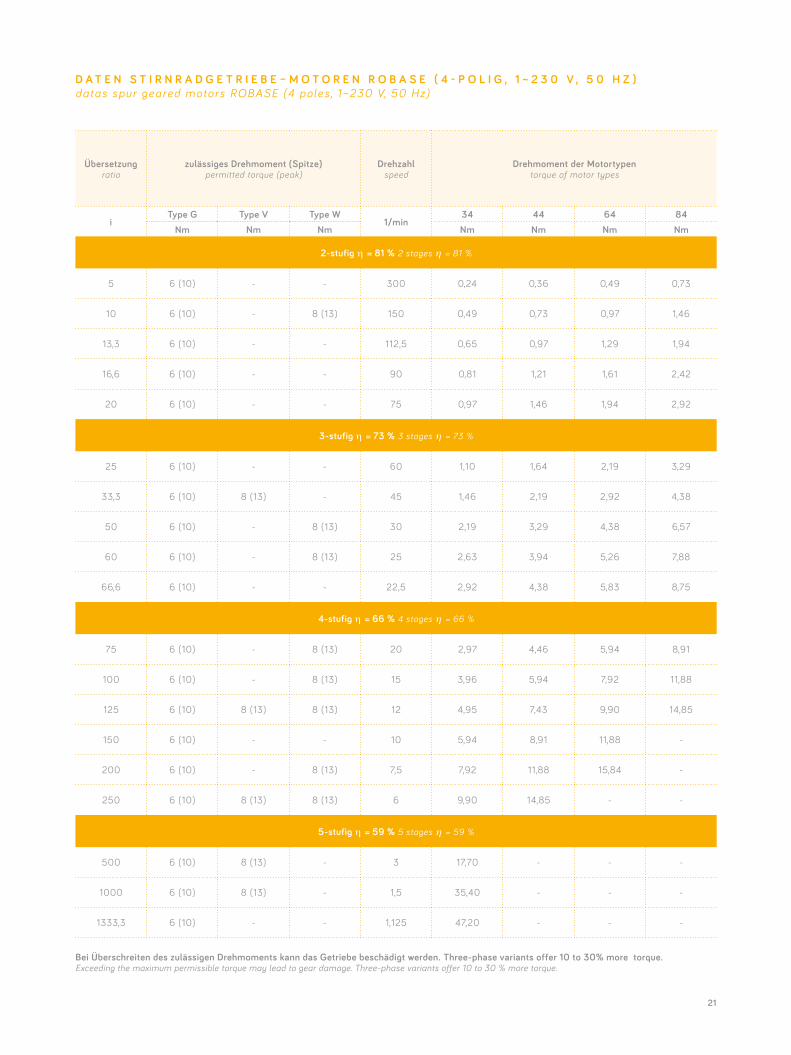
D A T E N S T I R N R A D G E T R I E B E – M O T O R E N R O B A S E ( 4 - P O L I G , 1 ~ 2 3 0 V , 5 0 H Z )datas spur geared motors ROBASE (4 poles , 1~230 V, 50 Hz)
Bei Überschreiten des zulässigen Drehmoments kann das Getriebe beschädigt werden. Three-phase variants offer 10 to 30% more torque. Exceeding the maximum permissible torque may lead to gear damage. Three-phase variants offer 10 to 30 % more torque.
22
Übersetzungratio
zulässiges Drehmoment (Spitze)permitted torque (peak)
Drehzahlspeed
Drehmoment 1 ~ Motortypentorque 1 ~ motor types
Drehmoment 3 ~ Motortypentorque 3~ motor types
iType G Type V Type W
1/min44 84 44 84
Nm Nm Nm Nm Nm Nm Nm
2-stufig η = 81 % 2 stages η = 81 %
5 6 (10) - - 300 0,53 0,93 1,30 -
10 6 (10) - 8 (13) 150 1,05 1,86 2,59 -
13,3 6 (10) - - 112,5 1,40 2,48 3,45 -
16,6 6 (10) - - 90 1,75 3,09 4,30 -
20 6 (10) - - 75 2,11 3,73 5,18 -
3-stufig η = 73 % 3 stages η = 73 %
25 6 (10) - - 60 2,37 4,20 5,84 -
33,3 6 (10) 8 (13) - 45 3,16 5,59 7,78 -
50 6 (10) - 8 (13) 30 4,75 8,40 11,68 -
60 6 (10) - 8 (13) 25 5,69 10,07 14,02 -
66,6 6 (10) - - 22,5 6,32 11,18 15,56 -
4-stufig η = 66 % 4 stages η = 66 %
75 6 (10) - 8 (13) 20 6,44 - - -
100 6 (10) - 8 (13) 15 8,58 - - -
125 6 (10) 8 (13) 8 (13) 12 10,73 - - -
150 6 (10) - - 10 12,87 - - -
200 6 (10) - 8 (13) 7,5 17,16 - - -
250 6 (10) 8 (13) 8 (13) 6 - - - -
5-stufig η = 59 % 5 stages η = 59 %
500 6 (10) 8 (13) - 3 - - - -
1000 6 (10) 8 (13) - 1,5 - - - -
1333,3 6 (10) - - 1,125 - - - -
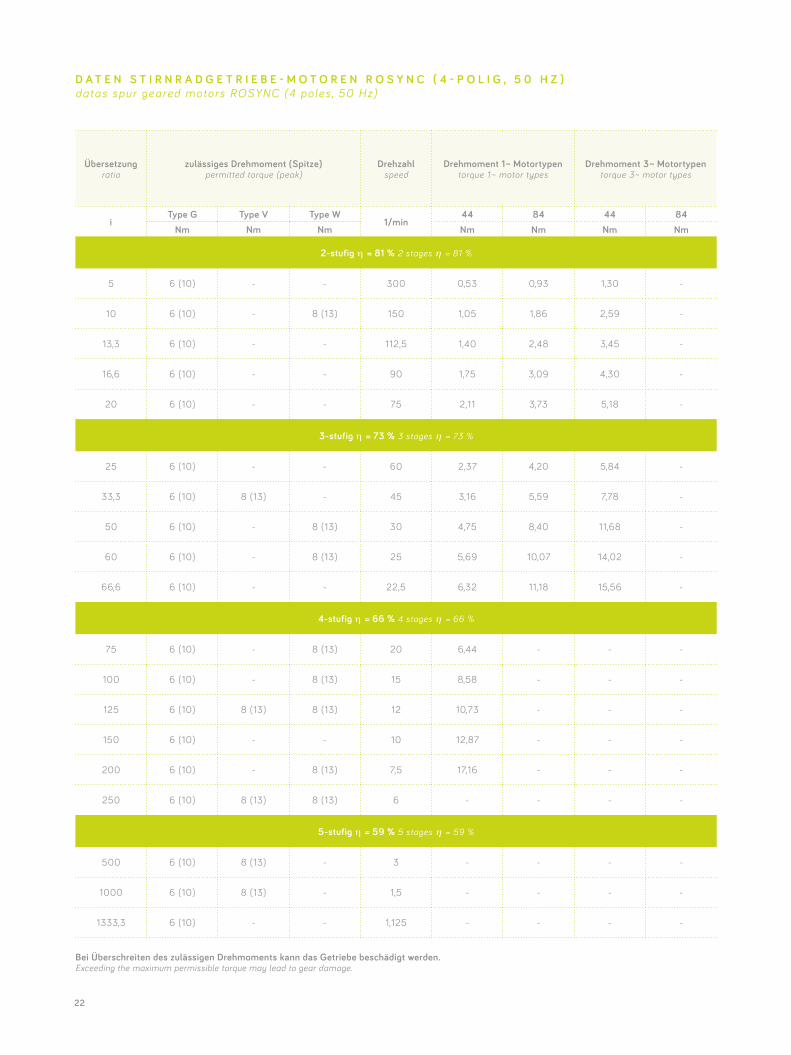
D A T E N S T I R N R A D G E T R I E B E - M O T O R E N R O S Y N C ( 4 - P O L I G , 5 0 H Z )datas spur geared motors ROSYNC (4 poles , 50 Hz)
Bei Überschreiten des zulässigen Drehmoments kann das Getriebe beschädigt werden. Exceeding the maximum permissible torque may lead to gear damage.
23
Übersetzungratio
zulässiges Drehmoment (Spitze)permitted torque (peak)
Drehzahlspeed
Drehmoment 1 ~ Motortypentorque 1 ~ motor types
Drehmoment 3 ~ Motortypentorque 3~ motor types
iType G Type V Type W
1/min44 84 44 84
Nm Nm Nm Nm Nm Nm Nm
2-stufig η = 81 % 2 stages η = 81 %
5 6 (10) - - 300 0,28 0,57 0,53 1,05
10 6 (10) - 8 (13) 150 0,57 1,13 1,05 2,11
13,3 6 (10) - - 112,5 0,75 1,51 1,40 2,80
16,6 6 (10) - - 90 0,94 1,88 1,75 3,50
20 6 (10) - - 75 1,13 2,27 2,11 4,21
3-stufig η = 73 % 3 stages η = 73 %
25 6 (10) - - 60 1,28 2,56 2,37 4,75
33,3 6 (10) 8 (13) - 45 1,70 3,40 3,16 6,32
50 6 (10) - 8 (13) 30 2,56 5,11 4,75 9,49
60 6 (10) - 8 (13) 25 3,07 6,13 5,69 11,39
66,6 6 (10) - - 22,5 3,40 6,81 6,32 12,64
4-stufig η = 66 % 4 stages η = 66 %
75 6 (10) - 8 (13) 20 3,47 6,93 6,44 12,87
100 6 (10) - 8 (13) 15 4,62 9,24 8,58 -
125 6 (10) 8 (13) 8 (13) 12 5,78 11,55 10,73 -
150 6 (10) - - 10 6,93 13,86 12,87 -
200 6 (10) - 8 (13) 7,5 9,24 - 17,16 -
250 6 (10) 8 (13) 8 (13) 6 11,55 - 21,45 -
5-stufig η = 59 % 5 stages η = 59 %
500 6 (10) 8 (13) - 3 20,65 - 38,35 -
1000 6 (10) 8 (13) - 1,5 41,30 - 76,70 -
1333,3 6 (10) - - 1,125 55,07 - 102,26 -
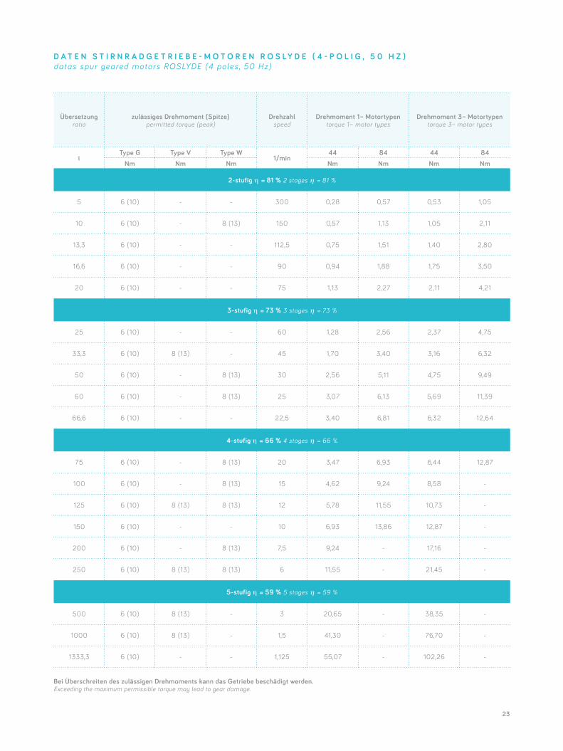
D A T E N S T I R N R A D G E T R I E B E - M O T O R E N R O S L Y D E ( 4 - P O L I G , 5 0 H Z )datas spur geared motors ROSLYDE (4 poles , 50 Hz)
Bei Überschreiten des zulässigen Drehmoments kann das Getriebe beschädigt werden. Exceeding the maximum permissible torque may lead to gear damage.
24
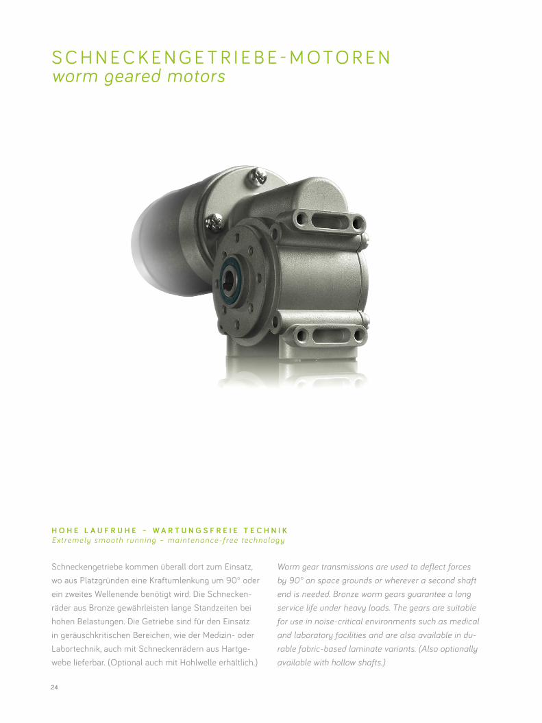
Schneckengetriebe kommen überall dort zum Einsatz, wo aus Platzgründen eine Kraftumlenkung um 90° oder ein zweites Wellenende benötigt wird. Die Schnecken- räder aus Bronze gewährleisten lange Standzeiten bei hohen Belastungen. Die Getriebe sind für den Einsatz in geräuschkritischen Bereichen, wie der Medizin- oder Labortechnik, auch mit Schneckenrädern aus Hartge- webe lieferbar. (Optional auch mit Hohlwelle erhältlich.)
S C H N E C K E N G E T R I E B E - M O T O R E N worm geared motors
Worm gear transmissions are used to deflect forces by 90° on space grounds or wherever a second shaft end is needed. Bronze worm gears guarantee a long service life under heavy loads. The gears are suitable for use in noise-critical environments such as medical and laboratory facilities and are also available in du- rable fabric-based laminate variants. (Also optionally available with hollow shafts.)
H O H E L A U F R U H E – W A R T U N G S F R E I E T E C H N I KExtremely smooth running – maintenance-f ree technolog y
25
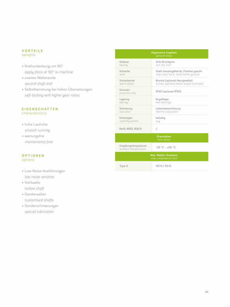
Allgemeine Angabengeneral datas
Gehäuse housing
Zink-Druckgusszinc die-cast
Schnecke worm
Stahl einsatzgehärtet, Flanken geschl. steel case-hard., tooth flanks ground
Schneckenrad worm wheel:
Bronze (optional Hartgewebe) bronze (optional fabric-based laminate)
Schutzart protection class IP40 (optional IP55)
Lagerung bearings
Kugellagerball bearings
Schmierung lubrication
Lebensdauerfettunglifetime lubrication
Einbaulagen assembly position
beliebigany
RoHS, WEEE, REACH √
Grenzdaten limit datas
Umgebungstemperaturen ambient temperatures -25 °C - +50 °C
Max. Radial-/Axiallastmax. radial /axial load
Type S 150 N / 100 N
V O R T E I L E benef i ts
• Kraftumlenkung um 90° apply force at 90° to machine• zweites Wellenende second shaft end• Selbsthemmung bei hohen Übersetzungen self-locking with higher gear ratios
E I G E N S C H A F T E N character is t ics
• hohe Laufruhe smooth running• wartungsfrei maintenance free
O P T I O N E N opt ions
• Low-Noise-Ausführungen low-noise versions• Hohlwelle hollow shaft• Sonderwellen customised shafts• Sonderschmierungen special lubrication
26
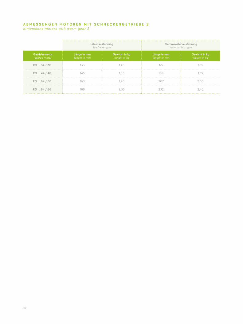
Litzenausführung lead wire type
Klemmkastenausführung terminal box type
Getriebemotorgeared motor
Länge in mm length in mm
Gewicht in kg weight in kg
Länge in mm length in mm
Gewicht in kg weight in kg
RO … 34 / 36 133 1,45 177 1,55
RO … 44 / 46 145 1,65 189 1,75
RO … 64 / 66 163 1,90 207 2,00
RO … 84 / 86 188 2,35 232 2,45
A B M E S S U N G E N M O T O R E N M I T S C H N E C K E N G E T R I E B E S dimens ions motors wi th worm gear S
27
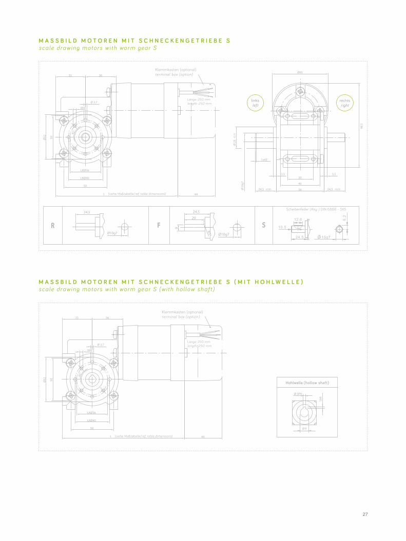
M A S S B I L D M O T O R E N M I T S C H N E C K E N G E T R I E B E S ( M I T H O H L W E L L E ) scale drawing motors wi th worm gear S (wi th hol low shaf t )
M A S S B I L D M O T O R E N M I T S C H N E C K E N G E T R I E B E S scale drawing motors wi th worm gear S
links left
rechts right
Scheibenfeder (Key ) DIN 6888 - 3X5
Klemmkasten (optional) terminal box (option)
length: 250 mm
(siehe Maßtabelle/ref. table dimensions)
10,5
12,6
24,5 10g7
6,2
Klemmkasten (optional) terminal box (option)
length: 250 mm
(siehe Maßtabelle/ref. table dimensions)
Hohlwelle (hollow shaft)
3P9
28
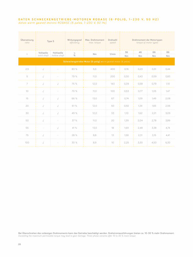
Übersetzungratio Type S Wirkungsgrad
efficiencyMax. Drehmoment
max. torqueDrehzahl
speedDrehmoment der Motortypen
torque of motor types
i Vollwelle solid shaft
Hohlwelle hollow shaft
η% Nm 1/min
36 46 66 86Nm Nm Nm Nm
Schneckengetriebe-Motor (6-polig) worm geared motor (6 poles)
2,5 √ - 83 % 5,3 400 0,16 0,23 0,31 0,44
5 √ - 79 % 11,0 200 0,30 0,43 0,59 0,83
7 √ √ 75 % 12,0 143 0,39 0,58 0,79 1,10
10 √ - 70 % 11,0 100 0,53 0,77 1,05 1,47
15 √ √ 66 % 13,0 67 0,74 1,09 1,49 2,08
20 √ √ 61 % 12,0 50 0,92 1,34 1,83 2,56
30 √ √ 49 % 12,0 33 1,10 1,62 2,21 3,09
50 √ - 37 % 11,0 20 1,39 2,04 2,78 3,89
55 - √ 41 % 13,0 18 1,69 2,48 3,38 4,74
75 √ - 28 % 8,8 13 1,58 2,31 3,15 4,41
100 √ - 30 % 8,9 10 2,25 3,30 4,50 6,30
D A T E N S C H N E C K E N G E T R I E B E - M O T O R E N R O B A S E ( 6 - P O L I G , 1 ~ 2 3 0 V , 5 0 H Z )datas worm geared motors ROBASE (6 poles , 1~230 V, 50 Hz)
Bei Überschreiten des zulässigen Drehmoments kann das Getriebe beschädigt werden. Drehstromausführungen bieten ca. 10-30 % mehr Drehmoment.Exceeding the maximum permissible torque may lead to gear damage. Three-phase variants offer 10 to 30 % more torque
29
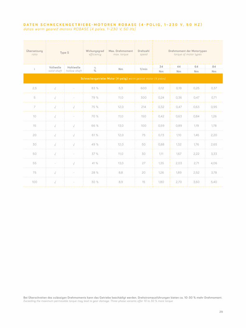
Übersetzungratio Type S Wirkungsgrad
efficiencyMax. Drehmoment
max. torqueDrehzahl
speedDrehmoment der Motortypen
torque of motor types
i Vollwelle solid shaft
Hohlwelle hollow shaft
η% Nm 1/min
34 44 64 84Nm Nm Nm Nm
Schneckengetriebe-Motor (4-polig) worm geared motor (4 poles)
2,5 √ - 83 % 5,3 600 0,12 0,19 0,25 0,37
5 √ - 79 % 11,0 300 0,24 0,36 0,47 0,71
7 √ √ 75 % 12,0 214 0,32 0,47 0,63 0,95
10 √ - 70 % 11,0 150 0,42 0,63 0,84 1,26
15 √ √ 66 % 13,0 100 0,59 0,89 1,19 1,78
20 √ √ 61 % 12,0 75 0,73 1,10 1,46 2,20
30 √ √ 49 % 12,0 50 0,88 1,32 1,76 2,65
50 √ - 37 % 11,0 30 1,11 1,67 2,22 3,33
55 - √ 41 % 13,0 27 1,35 2,03 2,71 4,06
75 √ - 28 % 8,8 20 1,26 1,89 2,52 3,78
100 √ - 30 % 8,9 15 1,80 2,70 3,60 5,40
D A T E N S C H N E C K E N G E T R I E B E - M O T O R E N R O B A S E ( 4 - P O L I G , 1 ~ 2 3 0 V , 5 0 H Z )datas worm geared motors ROBASE (4 poles , 1~230 V, 50 Hz)
Bei Überschreiten des zulässigen Drehmoments kann das Getriebe beschädigt werden. Drehstromausführungen bieten ca. 10-30 % mehr Drehmoment.Exceeding the maximum permissible torque may lead to gear damage. Three-phase variants offer 10 to 30 % more torque
30
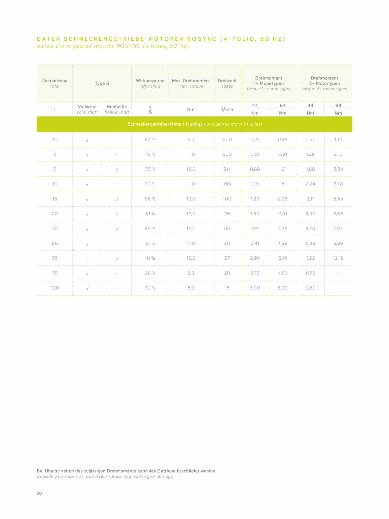
Übersetzungratio Type S Wirkungsgrad
efficiencyMax. Drehmoment
max. torqueDrehzahl
speed
Drehmoment 1 ~ Motortypen
torque 1 ~ motor types
Drehmoment 3 ~ Motortypen
torque 3~ motor types
i Vollwelle solid shaft
Hohlwelle hollow shaft
η% Nm 1/min
44 84 44 84Nm Nm Nm Nm
Schneckengetriebe-Motor (4-polig) worm geared motor (4 poles)
2,5 √ - 83 % 5,3 600 0,27 0,48 0,66 1,12
5 √ - 79 % 11,0 300 0,51 0,91 1,26 2,13
7 √ √ 75 % 12,0 214 0,68 1,21 1,68 2,84
10 √ - 70 % 11,0 150 0,91 1,61 2,24 3,78
15 √ √ 66 % 13,0 100 1,29 2,28 3,17 5,35
20 √ √ 61 % 12,0 75 1,59 2,81 3,90 6,59
30 √ √ 49 % 12,0 50 1,91 3,38 4,70 7,94
50 √ - 37 % 11,0 30 2,41 4,26 5,29 9,99
55 - √ 41 % 13,0 27 2,93 5,19 7,22 12,18
75 √ - 28 % 8,8 20 2,73 4,83 6,72 -
100 √ - 30 % 8,9 15 3,90 6,90 9,60 -
D A T E N S C H N E C K E N G E T R I E B E - M O T O R E N R O S Y N C ( 4 - P O L I G , 5 0 H Z )datas worm geared motors ROSYNC (4 poles , 50 Hz)
Bei Überschreiten des zulässigen Drehmoments kann das Getriebe beschädigt werden. Exceeding the maximum permissible torque may lead to gear damage.
31
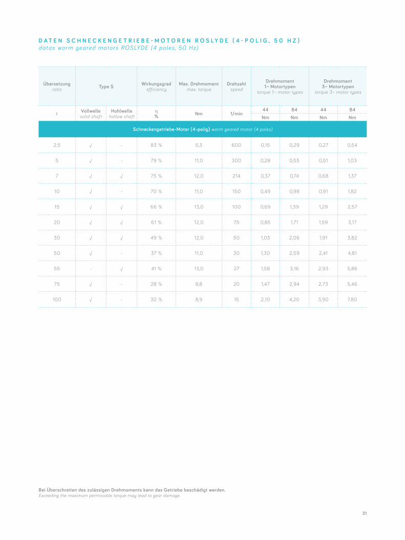
Übersetzungratio Type S Wirkungsgrad
efficiencyMax. Drehmoment
max. torqueDrehzahl
speed
Drehmoment 1 ~ Motortypen
torque 1 ~ motor types
Drehmoment 3 ~ Motortypen
torque 3~ motor types
i Vollwelle solid shaft
Hohlwelle hollow shaft
η% Nm 1/min
44 84 44 84Nm Nm Nm Nm
Schneckengetriebe-Motor (4-polig) worm geared motor (4 poles)
2,5 √ - 83 % 5,3 600 0,15 0,29 0,27 0,54
5 √ - 79 % 11,0 300 0,28 0,55 0,51 1,03
7 √ √ 75 % 12,0 214 0,37 0,74 0,68 1,37
10 √ - 70 % 11,0 150 0,49 0,98 0,91 1,82
15 √ √ 66 % 13,0 100 0,69 1,39 1,29 2,57
20 √ √ 61 % 12,0 75 0,85 1,71 1,59 3,17
30 √ √ 49 % 12,0 50 1,03 2,06 1,91 3,82
50 √ - 37 % 11,0 30 1,30 2,59 2,41 4,81
55 - √ 41 % 13,0 27 1,58 3,16 2,93 5,86
75 √ - 28 % 8,8 20 1,47 2,94 2,73 5,46
100 √ - 30 % 8,9 15 2,10 4,20 3,90 7,80
D A T E N S C H N E C K E N G E T R I E B E - M O T O R E N R O S L Y D E ( 4 - P O L I G , 5 0 H Z )datas worm geared motors ROSLYDE (4 poles , 50 Hz)
Bei Überschreiten des zulässigen Drehmoments kann das Getriebe beschädigt werden. Exceeding the maximum permissible torque may lead to gear damage.
32
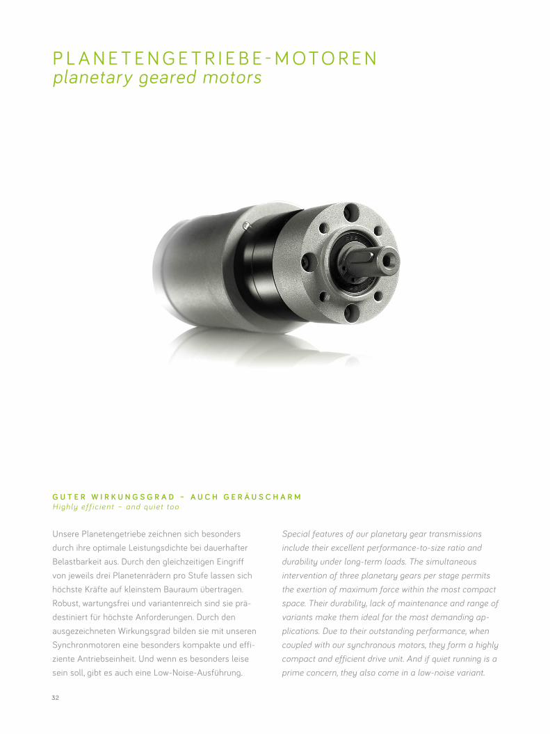
Unsere Planetengetriebe zeichnen sich besonders durch ihre optimale Leistungsdichte bei dauerhafter Belastbarkeit aus. Durch den gleichzeitigen Eingriff von jeweils drei Planetenrädern pro Stufe lassen sich höchste Kräfte auf kleinstem Bauraum übertragen. Robust, wartungsfrei und variantenreich sind sie prä- destiniert für höchste Anforderungen. Durch den ausgezeichneten Wirkungsgrad bilden sie mit unseren Synchronmotoren eine besonders kompakte und effi- ziente Antriebseinheit. Und wenn es besonders leise sein soll, gibt es auch eine Low-Noise-Ausführung.
P L A N E T E N G E T R I E B E - M O T O R E N planetary geared motors
Special features of our planetary gear transmissions include their excellent performance-to-size ratio and durability under long-term loads. The simultaneous intervention of three planetary gears per stage permits the exertion of maximum force within the most compact space. Their durability, lack of maintenance and range of variants make them ideal for the most demanding ap-plications. Due to their outstanding performance, when coupled with our synchronous motors, they form a highly compact and efficient drive unit. And if quiet running is a prime concern, they also come in a low-noise variant.
G U T E R W I R K U N G S G R A D – A U C H G E R Ä U S C H A R MHighly ef f ic ient – and qu iet too
33
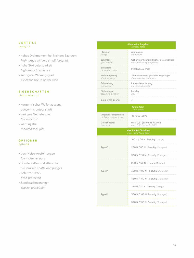
Allgemeine Angabengeneral datas
Flansch flange
Aluminiumaluminium
Zahnräder gear wheels
Gehärteter Stahl mit hoher Belastbarkeit hardened heavy duty steel
Schutzart protection class IP40 (optional IP53)
Wellenlagerung shaft bearings
2 hintereinander gestellte Kugellager2 consecutive ball races
Schmierung lubrication
Lebensdauerfettunglife-time lubrication
Einbaulagen assembly position
beliebigany
RoHS, WEEE, REACH √
Grenzdaten limit datas
Umgebungstemperaturen ambient temperatures -15 °C bis +60 °C
Getriebespiel backlash
max. 0,9° (Baureihe R: 2,0°)max. 0.9° (series R: 2.0°)
Max. Radial-/Axiallastmax. radial /axial load
Type Q
160 N / 50 N 1-stufig (1 stage)
230 N / 80 N 2-stufig (2 stages)
300 N / 110 N 3-stufig (3 stages)
Type P
200 N / 60 N 1-stufig (1 stage)
320 N / 100 N 2-stufig (2 stages)
450 N / 150 N 3-stufig (3 stages)
Type R
240 N / 70 N 1-stufig (1 stage)
360 N / 100 N 2-stufig (2 stages)
520 N / 150 N 3-stufig (3 stages)
V O R T E I L E benef i ts
• hohes Drehmoment bei kleinem Bauraum high torque within a small footprint• hohe Stoßbelastbarkeit high impact resilience• sehr guter Wirkungsgrad excellent size to power ratio
E I G E N S C H A F T E N character is t ics
• konzentrischer Wellenausgang concentric output shaft• geringes Getriebespiel low backlash• wartungsfrei maintenance free
O P T I O N E N opt ions
• Low-Noise-Ausführungen low-noise versions• Sonderwellen und -flansche customised shafts and flanges• Schutzart IP53 IP53 protected• Sonderschmierungen special lubrication
34
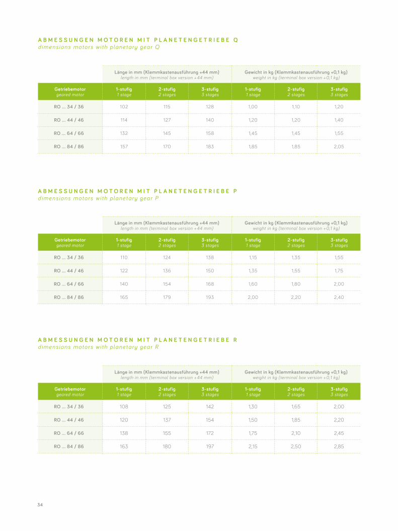
Länge in mm (Klemmkastenausführung +44 mm) length in mm (terminal box version + 44 mm)
Gewicht in kg (Klemmkastenausführung +0,1 kg) weight in kg (terminal box version + 0,1 kg)
Getriebemotorgeared motor
1-stufig1 stage
2-stufig2 stages
3-stufig3 stages
1-stufig1 stage
2-stufig2 stages
3-stufig3 stages
RO … 34 / 36 102 115 128 1,00 1,10 1,20
RO … 44 / 46 114 127 140 1,20 1,20 1,40
RO … 64 / 66 132 145 158 1,45 1,45 1,55
RO … 84 / 86 157 170 183 1,85 1,85 2,05
Länge in mm (Klemmkastenausführung +44 mm) length in mm (terminal box version + 44 mm)
Gewicht in kg (Klemmkastenausführung +0,1 kg) weight in kg (terminal box version + 0,1 kg)
Getriebemotorgeared motor
1-stufig1 stage
2-stufig2 stages
3-stufig3 stages
1-stufig1 stage
2-stufig2 stages
3-stufig3 stages
RO … 34 / 36 110 124 138 1,15 1,35 1,55
RO … 44 / 46 122 136 150 1,35 1,55 1,75
RO … 64 / 66 140 154 168 1,60 1,80 2,00
RO … 84 / 86 165 179 193 2,00 2,20 2,40
Länge in mm (Klemmkastenausführung +44 mm) length in mm (terminal box version + 44 mm)
Gewicht in kg (Klemmkastenausführung +0,1 kg) weight in kg (terminal box version + 0,1 kg)
Getriebemotorgeared motor
1-stufig1 stage
2-stufig2 stages
3-stufig3 stages
1-stufig1 stage
2-stufig2 stages
3-stufig3 stages
RO … 34 / 36 108 125 142 1,30 1,65 2,00
RO … 44 / 46 120 137 154 1,50 1,85 2,20
RO … 64 / 66 138 155 172 1,75 2,10 2,45
RO … 84 / 86 163 180 197 2,15 2,50 2,85
A B M E S S U N G E N M O T O R E N M I T P L A N E T E N G E T R I E B E Q dimens ions motors wi th planetary gear Q
A B M E S S U N G E N M O T O R E N M I T P L A N E T E N G E T R I E B E P dimens ions motors wi th planetary gear P
A B M E S S U N G E N M O T O R E N M I T P L A N E T E N G E T R I E B E R dimens ions motors wi th planetary gear R
35
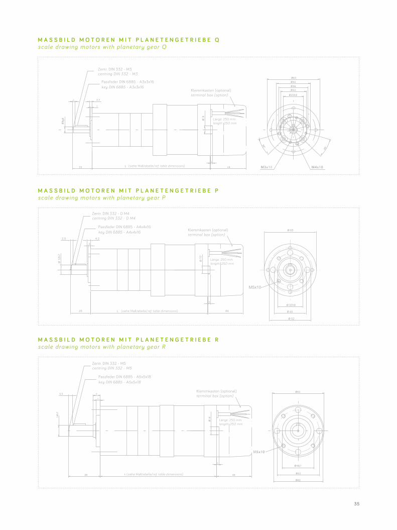
M A S S B I L D M O T O R E N M I T P L A N E T E N G E T R I E B E Q scale drawing motors wi th planetary gear Q
M A S S B I L D M O T O R E N M I T P L A N E T E N G E T R I E B E R scale drawing motors wi th planetary gear R
M A S S B I L D M O T O R E N M I T P L A N E T E N G E T R I E B E P scale drawing motors wi th planetary gear P
Klemmkasten (optional) terminal box (option)
length: 250 mm
(siehe Maßtabelle/ref. table dimensions)
Zentr. DIN 332 - M3 centring DIN 332 - M3
Passfeder DIN 6885 - A3x3x16 key DIN 6885 - A3x3x16
3
3
4,22,5
M5x10
44L25
Klemmkasten (optional) terminal box (option)
Zentr. DIN 332 - D M4 centring DIN 332 - D M4
Passfeder DIN 6885 - A4x4x16 key DIN 6885 - A4x4x16
length: 250 mm
(siehe Maßtabelle/ref. table dimensions)
Klemmkasten (optional) terminal box (option)
length: 250 mm
(siehe Maßtabelle/ref. table dimensions)
Zentr. DIN 332 - M5 centring DIN 332 - M5
Passfeder DIN 6885 - A5x5x18 key DIN 6885 - A5x5x18
36
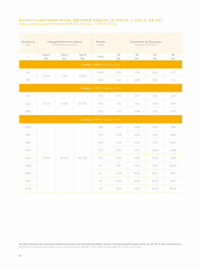
Übersetzungratio
zulässiges Drehmoment (Spitze)permitted torque (peak)
Drehzahlspeed
Drehmoment der Motortypentorque of motor types
iType Q Type P Type R
1/min36 46 66 86
Nm Nm Nm Nm Nm Nm Nm
1-stufig η = 80 % 1 stage η = 80 %
4,33 (4,5) 4 (6) 8 (12)
232,6 0,26 0,38 0,52 0,72
6,8 147,1 0,41 0,60 0,82 1,14
2-stufig η = 75 % 2 stages η = 75 %
13,7
7,5 (11) 12 (18) 25 (37)
73,0 0,77 1,13 1,54 2,16
22,2 45,0 1,25 1,83 2,50 3,50
28,9 34,6 1,63 2,38 3,25 4,55
3-stufig η = 70 % 3 stages η = 70 %
50,9
15 (22) 25 (37) 50 (75)
19,6 2,67 3,92 5,34 7,48
58,9 17,0 3,09 4,54 6,18 8,66
68,1 14,7 3,58 5,24 7,15 10,01
95,2 10,5 5,00 7,33 10,00 13,99
124,4 8,0 6,53 9,58 13,06 18,29
149,9 6,7 7,87 11,54 15,74 22,04
195,3 5,1 10,25 15,04 20,51 28,71
236,1 4,2 12,40 18,18 24,79 34,71
307,8 3,2 16,16 23,07 32,32 45,25
D A T E N P L A N E T E N G E T R I E B E - M O T O R E N R O B A S E ( 6 - P O L I G , 1 ~ 2 3 0 V , 5 0 H Z )datas planetary geared motors ROBASE (6 poles , 1~230 V, 50 Hz)
Bei Überschreiten des zulässigen Drehmoments kann das Getriebe beschädigt werden. Drehstromausführungen bieten ca. 10-30 % mehr Drehmoment.Exceeding the maximum permissible torque may lead to gear damage. Three-phase variants offer 10 to 30 % more torque
37
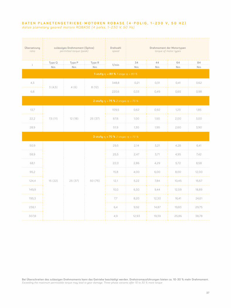
Übersetzungratio
zulässiges Drehmoment (Spitze)permitted torque (peak)
Drehzahlspeed
Drehmoment der Motortypentorque of motor types
iType Q Type P Type R
1/min34 44 64 84
Nm Nm Nm Nm Nm Nm Nm
1-stufig η = 80 % 1 stage η = 80 %
4,33 (4,5) 4 (6) 8 (12)
348,8 0,21 0,31 0,41 0,62
6,8 220,6 0,33 0,49 0,65 0,98
2-stufig η = 75 % 2 stages η = 75 %
13,7
7,5 (11) 12 (18) 25 (37)
109,5 0,62 0,92 1,23 1,85
22,2 67,6 1,00 1,50 2,00 3,00
28,9 51,9 1,30 1,95 2,60 3,90
3-stufig η = 70 % 3 stages η = 70 %
50,9
15 (22) 25 (37) 50 (75)
29,5 2,14 3,21 4,28 6,41
58,9 25,5 2,47 3,71 4,95 7,42
68,1 22,0 2,86 4,29 5,72 8,58
95,2 15,8 4,00 6,00 8,00 12,00
124,4 12,1 5,22 7,84 10,45 15,67
149,9 10,0 6,30 9,44 12,59 18,89
195,3 7,7 8,20 12,30 16,41 24,61
236,1 6,4 9,92 14,87 19,83 29,75
307,8 4,9 12,93 19,39 25,86 38,78
D A T E N P L A N E T E N G E T R I E B E - M O T O R E N R O B A S E ( 4 - P O L I G , 1 ~ 2 3 0 V , 5 0 H Z )datas planetary geared motors ROBASE (4 poles , 1~230 V, 50 Hz)
Bei Überschreiten des zulässigen Drehmoments kann das Getriebe beschädigt werden. Drehstromausführungen bieten ca. 10-30 % mehr Drehmoment.Exceeding the maximum permissible torque may lead to gear damage. Three-phase variants offer 10 to 30 % more torque
38
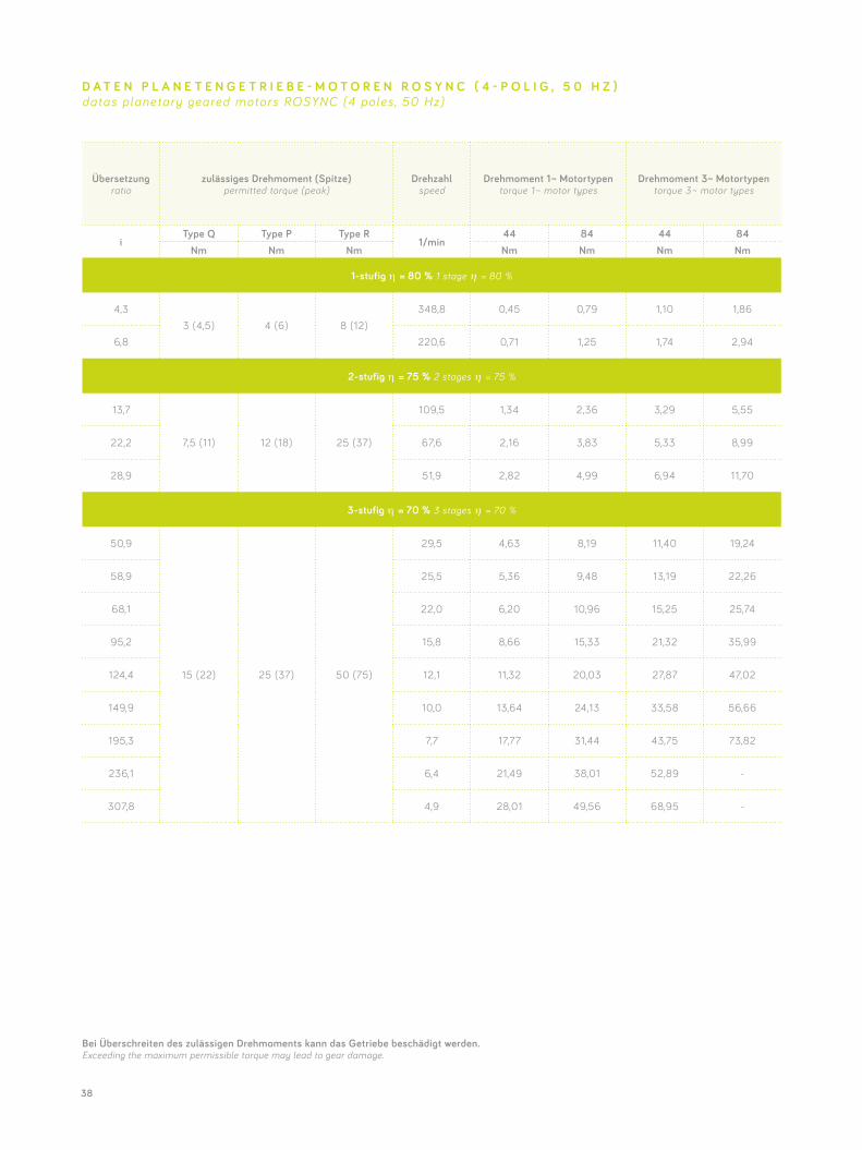
Übersetzungratio
zulässiges Drehmoment (Spitze)permitted torque (peak)
Drehzahlspeed
Drehmoment 1 ~ Motortypentorque 1 ~ motor types
Drehmoment 3~ Motortypentorque 3 ~ motor types
iType Q Type P Type R
1/min44 84 44 84
Nm Nm Nm Nm Nm Nm Nm
1-stufig η = 80 % 1 stage η = 80 %
4,33 (4,5) 4 (6) 8 (12)
348,8 0,45 0,79 1,10 1,86
6,8 220,6 0,71 1,25 1,74 2,94
2-stufig η = 75 % 2 stages η = 75 %
13,7
7,5 (11) 12 (18) 25 (37)
109,5 1,34 2,36 3,29 5,55
22,2 67,6 2,16 3,83 5,33 8,99
28,9 51,9 2,82 4,99 6,94 11,70
3-stufig η = 70 % 3 stages η = 70 %
50,9
15 (22) 25 (37) 50 (75)
29,5 4,63 8,19 11,40 19,24
58,9 25,5 5,36 9,48 13,19 22,26
68,1 22,0 6,20 10,96 15,25 25,74
95,2 15,8 8,66 15,33 21,32 35,99
124,4 12,1 11,32 20,03 27,87 47,02
149,9 10,0 13,64 24,13 33,58 56,66
195,3 7,7 17,77 31,44 43,75 73,82
236,1 6,4 21,49 38,01 52,89 -
307,8 4,9 28,01 49,56 68,95 -
D A T E N P L A N E T E N G E T R I E B E - M O T O R E N R O S Y N C ( 4 - P O L I G , 5 0 H Z )datas planetary geared motors ROSYNC (4 poles , 50 Hz)
Bei Überschreiten des zulässigen Drehmoments kann das Getriebe beschädigt werden. Exceeding the maximum permissible torque may lead to gear damage.
39
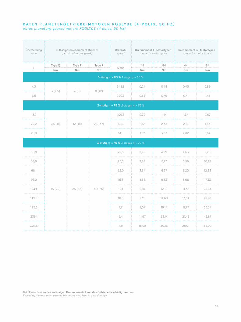
Übersetzungratio
zulässiges Drehmoment (Spitze)permitted torque (peak)
Drehzahlspeed
Drehmoment 1 ~ Motortypentorque 1 ~ motor types
Drehmoment 3~ Motortypentorque 3 ~ motor types
iType Q Type P Type R
1/min44 84 44 84
Nm Nm Nm Nm Nm Nm Nm
1-stufig η = 80 % 1 stage η = 80 %
4,33 (4,5) 4 (6) 8 (12)
348,8 0,24 0,48 0,45 0,89
6,8 220,6 0,38 0,76 0,71 1,41
2-stufig η = 75 % 2 stages η = 75 %
13,7
7,5 (11) 12 (18) 25 (37)
109,5 0,72 1,44 1,34 2,67
22,2 67,6 1,17 2,33 2,16 4,33
28,9 51,9 1,52 3,03 2,82 5,64
3-stufig η = 70 % 3 stages η = 70 %
50,9
15 (22) 25 (37) 50 (75)
29,5 2,49 4,99 4,63 9,26
58,9 25,5 2,89 5,77 5,36 10,72
68,1 22,0 3,34 6,67 6,20 12,33
95,2 15,8 4,66 9,33 8,66 17,33
124,4 12,1 6,10 12,19 11,32 22,64
149,9 10,0 7,35 14,69 13,64 27,28
195,3 7,7 9,57 19,14 17,77 35,54
236,1 6,4 11,57 23,14 21,49 42,87
307,8 4,9 15,08 30,16 28,01 56,02
D A T E N P L A N E T E N G E T R I E B E - M O T O R E N R O S L Y D E ( 4 - P O L I G , 5 0 H Z )datas planetary geared motors ROSLYDE (4 poles , 50 Hz)
Bei Überschreiten des zulässigen Drehmoments kann das Getriebe beschädigt werden. Exceeding the maximum permissible torque may lead to gear damage.
40
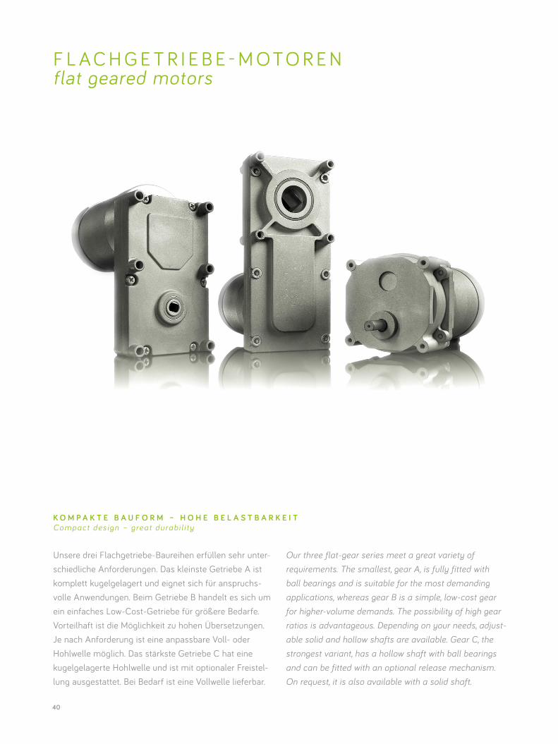
Unsere drei Flachgetriebe-Baureihen erfüllen sehr unter- schiedliche Anforderungen. Das kleinste Getriebe A ist komplett kugelgelagert und eignet sich für anspruchs-volle Anwendungen. Beim Getriebe B handelt es sich um ein einfaches Low-Cost-Getriebe für größere Bedarfe. Vorteilhaft ist die Möglichkeit zu hohen Übersetzungen. Je nach Anforderung ist eine anpassbare Voll- oder Hohlwelle möglich. Das stärkste Getriebe C hat eine kugelgelagerte Hohlwelle und ist mit optionaler Freistel-lung ausgestattet. Bei Bedarf ist eine Vollwelle lieferbar.
F L A C H G E T R I E B E - M O T O R E N flat geared motors
Our three flat-gear series meet a great variety of requirements. The smallest, gear A, is fully fitted with ball bearings and is suitable for the most demanding applications, whereas gear B is a simple, low-cost gear for higher-volume demands. The possibility of high gear ratios is advantageous. Depending on your needs, adjust- able solid and hollow shafts are available. Gear C, the strongest variant, has a hollow shaft with ball bearings and can be fitted with an optional release mechanism. On request, it is also available with a solid shaft.
K O M P A K T E B A U F O R M – H O H E B E L A S T B A R K E I TCompact des ign – great durab i l i ty
41
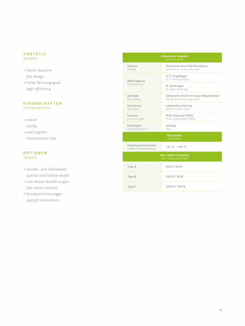
Allgemeine Angabengeneral datas
Gehäuse housing
Aluminium-bzw Zink-Druckgussaluminium or zinc die-cast
Wellenlagerung shaft bearings
A, C: Kugellager A, C: ball bearings
B: Sinterlager B: sinter bearings
Zahnräder gear wheels
Gehärteter Stahl mit hoher Belastbarkeit hardened heavy duty steel
Schmierung lubrication
Lebensdauerfettunglifetime lubrication
Schutzart protection class
IP40 (optional IP55)IP40 (optionally IP 55)
Einbaulagen assembly position
beliebigany
Grenzdaten limit datas
Umgebungstemperaturen ambient temperatures -10 °C - +40 °C
Max. Radial-/Axiallastmax. radial /axial load
Type A 60 N / 50 N
Type B 120 N / 30 N
Type C 320 N / 100 N
V O R T E I L E benef i ts
• flache Bauform flat design• hoher Wirkungsgrad high efficiency
E I G E N S C H A F T E N character is t ics
• robust sturdy• wartungsfrei maintenance free
O P T I O N E N opt ions
• Sonder- und Hohlwellen special and hollow shafts• Low-Noise-Ausführungen low-noise versions• Sonderschmierungen special lubrications
42
Litzenausführung lead wire type
Klemmkastenausführung terminal box type
Getriebemotorgeared motor
Länge in mm length in mm
Gewicht in kg weight in kg
Länge in mm length in mm
Gewicht in kg weight in kg
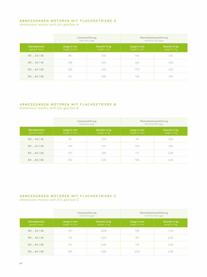
RO … 34 / 36 96 1,00 140 1,10
RO … 44 / 46 108 1,20 152 1,30
RO … 64 / 66 126 1,45 170 1,55
RO … 84 / 86 151 1,85 195 1,95
Litzenausführung lead wire type
Klemmkastenausführung terminal box type
Getriebemotorgeared motor
Länge in mm length in mm
Gewicht in kg weight in kg
Länge in mm length in mm
Gewicht in kg weight in kg
RO … 34 / 36 97 1,50 141 1,60
RO … 44 / 46 109 1,70 153 1,80
RO … 64 / 66 127 1,95 171 2,05
RO … 84 / 86 152 2,35 196 2,45
Litzenausführung lead wire type
Klemmkastenausführung terminal box type
Getriebemotorgeared motor
Länge in mm length in mm
Gewicht in kg weight in kg
Länge in mm length in mm
Gewicht in kg weight in kg
RO … 34 / 36 101 2,00 145 2,10
RO … 44 / 46 113 2,20 157 2,30
RO … 64 / 66 131 2,45 175 2,55
RO … 84 / 86 156 2,85 200 2,95
A B M E S S U N G E N M O T O R E N M I T F L A C H G E T R I E B E A dimens ions motors wi th f la t gearbox A
A B M E S S U N G E N M O T O R E N M I T F L A C H G E T R I E B E B dimens ions motors wi th f la t gearbox B
A B M E S S U N G E N M O T O R E N M I T F L A C H G E T R I E B E C dimens ions motors wi th f la t gearbox C
43
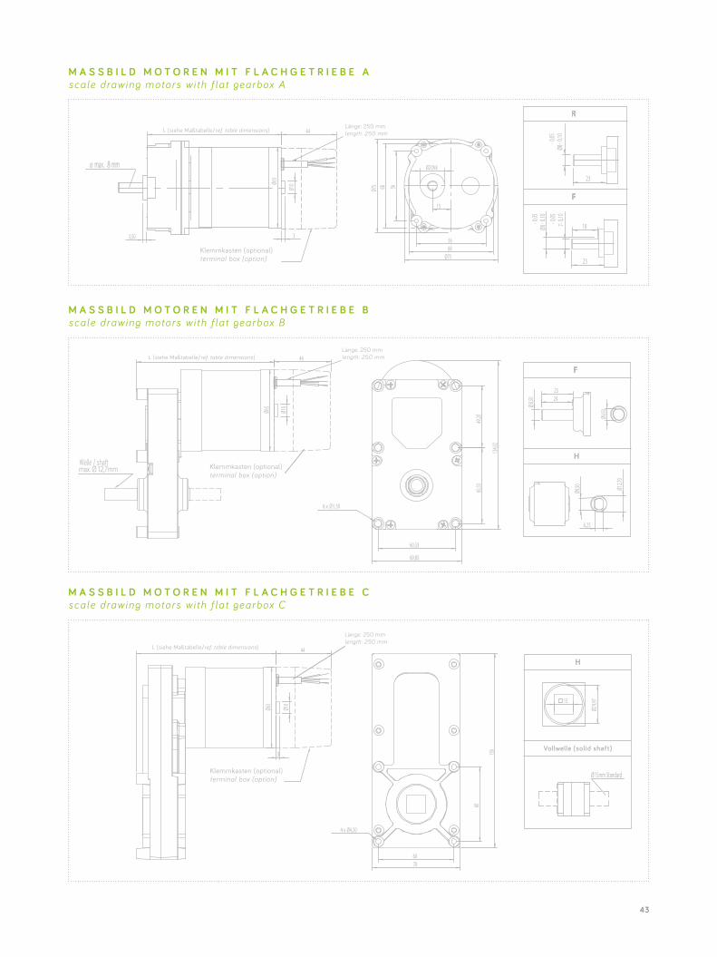
M A S S B I L D M O T O R E N M I T F L A C H G E T R I E B E A scale drawing motors wi th f la t gearbox A
M A S S B I L D M O T O R E N M I T F L A C H G E T R I E B E C scale drawing motors wi th f la t gearbox C
M A S S B I L D M O T O R E N M I T F L A C H G E T R I E B E B scale drawing motors wi th f la t gearbox B
15
Ø20h8
56
56
68
68
Ø75
Ø75
23
23
183,50
44
3
Ø65
Ø10
Ø max. mm
Klemmkasten (optional) terminal box (option)
length: 250 mmL (siehe Maßtabelle/ref. table dimensions)
8
7--0,05 0,1
0-0
,05- 0
,10Ø8
-0,05
- 0,10
Ø860,33
69,85
60,33
49,20
134,0
2
6 x Ø 5.50
length: 250 mm
Ø10
Ø65
44
Welle / shaftmax. Ø 12,7mm Klemmkasten (optional)
terminal box (option)
L (siehe Maßtabelle/ref. table dimensions)
Ø8,50 2425
Ø9,50
6,25
9Ø5,0 Ø1
2,70
length: 250 mm
44
Ø10
Ø65
3
Klemmkasten (optional) terminal box (option)
L (siehe Maßtabelle/ref. table dimensions)
4 x
60
60
70
156
Ø4,20
Vollwelle (solid shaft)
Ø 15mm Standard
15
Ø29,9
7
44
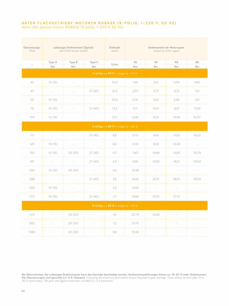
Übersetzungr-Ratio
zulässiges Drehmoment (Spitze)permitted torque (peak)
Drehzahlspeed
Drehmoment der Motortypentorque of motor types
iType A Type B Type C
1/min36 46 66 86
Nm Nm Nm Nm Nm Nm Nm
3-stufig η = 73 % 3 stages η = 73 %
30 10 (15) - - 33,3 1,64 2,41 3,29 4,60
47 - - 27 (40) 21,3 2,57 3,77 5,15 7,21
50 10 (15) - - 20,0 2,74 4,02 5,48 7,67
75 10 (15) - 27 (40) 13,3 4,11 6,02 8,21 11,50
100 10 (15) - - 10,0 5,48 8,03 10,95 15,33 *
4-stufig η = 66 % 4 stages η = 66 %
117 - - 27 (40) 8,5 5,79 8,49 11,58 16,22
125 10 (15) - - 8,0 6,19 9,08 12,38 -
150 10 (15) 20 (30) 27 (40) 6,7 7,43 10,89 14,85 20,79
187 - - 27 (40) 5,3 9,26 13,58 18,51 25,92
250 10 (15) 20 (30) - 4,0 12,38 - - -
288 - - 27 (40) 3,5 14,26 20,91 28,51 39,92
300 10 (15) - - 3,3 14,85 - - -
375 10 (15) - 27 (40) 2,7 18,56 27,23 37,13 -
5-stufig η = 59 % 5 stages η = 59 %
513 - 20 (30) - 1,9 22,70 33,29 - -
853 - 20 (30) - 1,2 37,75 - - -
1586 - 20 (30) - 0,6 70,18 - - -
D A T E N F L A C H G E T R I E B E - M O T O R E N R O B A S E ( 6 - P O L I G , 1 ~ 2 3 0 V , 5 0 H Z )datas f lat geared motors ROBASE (6 poles , 1~230 V, 50 Hz)
Bei Überschreiten des zulässigen Drehmoments kann das Getriebe beschädigt werden. Drehstromausführungen bieten ca. 10-30 % mehr Drehmoment. Die Übersetzungen sind gerundet (+/-3 % Toleranz). Exceeding the maximum permissible torque may lead to gear damage. Three-phase variants offer 10 to 30 % more torque. The gear ratio figures have been rounded (+/–3 % tolerance).
45
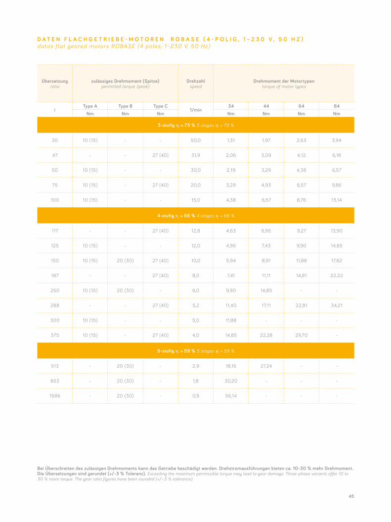
Übersetzungratio
zulässiges Drehmoment (Spitze)permitted torque (peak)
Drehzahlspeed
Drehmoment der Motortypentorque of motor types
iType A Type B Type C
1/min34 44 64 84
Nm Nm Nm Nm Nm Nm Nm
3-stufig η = 73 % 3 stages η = 73 %
30 10 (15) - - 50,0 1,31 1,97 2,63 3,94
47 - - 27 (40) 31,9 2,06 3,09 4,12 6,18
50 10 (15) - - 30,0 2,19 3,29 4,38 6,57
75 10 (15) - 27 (40) 20,0 3,29 4,93 6,57 9,86
100 10 (15) - - 15,0 4,38 6,57 8,76 13,14
4-stufig η = 66 % 4 stages η = 66 %
117 - - 27 (40) 12,8 4,63 6,95 9,27 13,90
125 10 (15) - - 12,0 4,95 7,43 9,90 14,85
150 10 (15) 20 (30) 27 (40) 10,0 5,94 8,91 11,88 17,82
187 - - 27 (40) 8,0 7,41 11,11 14,81 22,22
250 10 (15) 20 (30) - 6,0 9,90 14,85 - -
288 - - 27 (40) 5,2 11,40 17,11 22,81 34,21
300 10 (15) - - 5,0 11,88 - - -
375 10 (15) - 27 (40) 4,0 14,85 22,28 29,70 -
5-stufig η = 59 % 5 stages η = 59 %
513 - 20 (30) - 2,9 18,16 27,24 - -
853 - 20 (30) - 1,8 30,20 - - -
1586 - 20 (30) - 0,9 56,14 - - -
D A T E N F L A C H G E T R I E B E - M O T O R E N R O B A S E ( 4 - P O L I G , 1 ~ 2 3 0 V , 5 0 H Z )datas f lat geared motors ROBASE (4 poles , 1~230 V, 50 Hz)
Bei Überschreiten des zulässigen Drehmoments kann das Getriebe beschädigt werden. Drehstromausführungen bieten ca. 10-30 % mehr Drehmoment. Die Übersetzungen sind gerundet (+/-3 % Toleranz). Exceeding the maximum permissible torque may lead to gear damage. Three-phase variants offer 10 to 30 % more torque. The gear ratio figures have been rounded (+/–3 % tolerance).
46
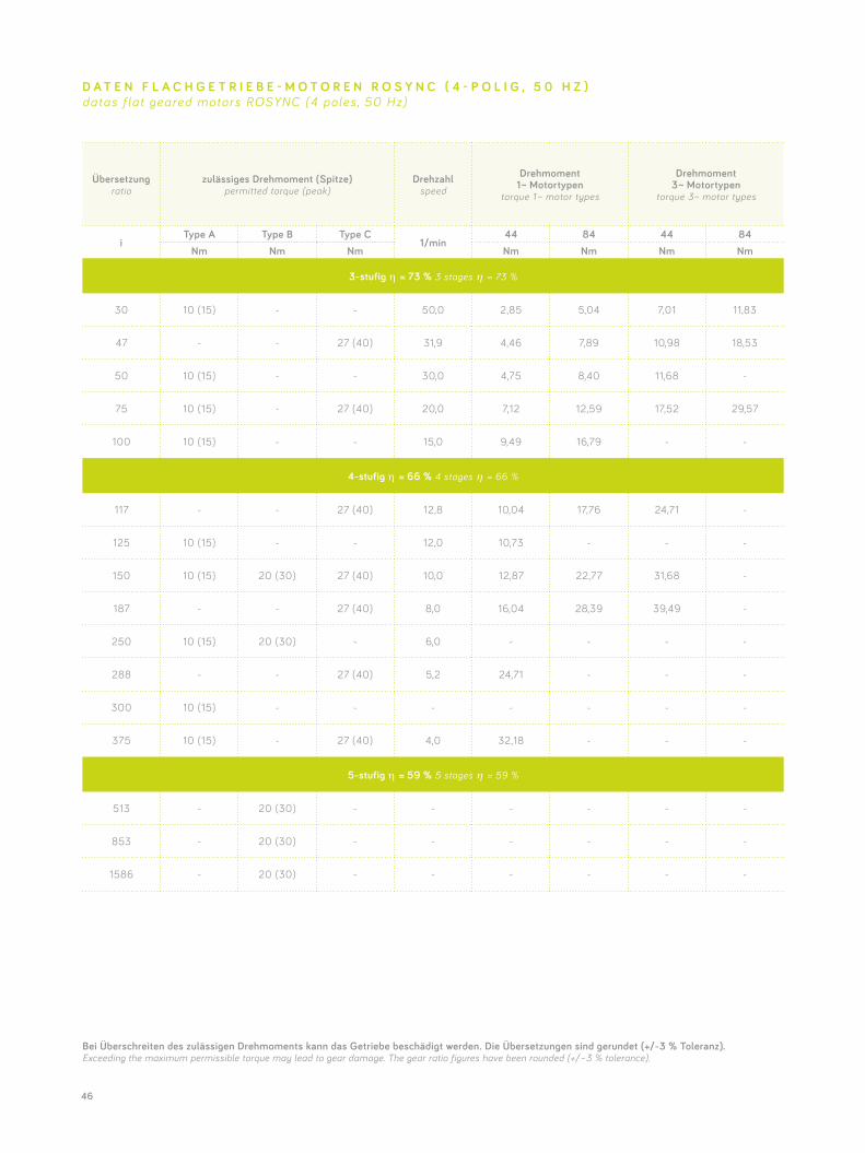
Übersetzungratio
zulässiges Drehmoment (Spitze)permitted torque (peak)
Drehzahlspeed
Drehmoment 1 ~ Motortypen
torque 1 ~ motor types
Drehmoment 3 ~ Motortypen
torque 3~ motor types
iType A Type B Type C
1/min44 84 44 84
Nm Nm Nm Nm Nm Nm Nm
3-stufig η = 73 % 3 stages η = 73 %
30 10 (15) - - 50,0 2,85 5,04 7,01 11,83
47 - - 27 (40) 31,9 4,46 7,89 10,98 18,53
50 10 (15) - - 30,0 4,75 8,40 11,68 -
75 10 (15) - 27 (40) 20,0 7,12 12,59 17,52 29,57
100 10 (15) - - 15,0 9,49 16,79 - -
4-stufig η = 66 % 4 stages η = 66 %
117 - - 27 (40) 12,8 10,04 17,76 24,71 -
125 10 (15) - - 12,0 10,73 - - -
150 10 (15) 20 (30) 27 (40) 10,0 12,87 22,77 31,68 -
187 - - 27 (40) 8,0 16,04 28,39 39,49 -
250 10 (15) 20 (30) - 6,0 - - - -
288 - - 27 (40) 5,2 24,71 - - -
300 10 (15) - - - - - - -
375 10 (15) - 27 (40) 4,0 32,18 - - -
5-stufig η = 59 % 5 stages η = 59 %
513 - 20 (30) - - - - - -
853 - 20 (30) - - - - - -
1586 - 20 (30) - - - - - -
D A T E N F L A C H G E T R I E B E - M O T O R E N R O S Y N C ( 4 - P O L I G , 5 0 H Z )datas f lat geared motors ROSYNC (4 poles , 50 Hz)
Bei Überschreiten des zulässigen Drehmoments kann das Getriebe beschädigt werden. Die Übersetzungen sind gerundet (+/-3 % Toleranz). Exceeding the maximum permissible torque may lead to gear damage. The gear ratio figures have been rounded (+/–3 % tolerance).
47
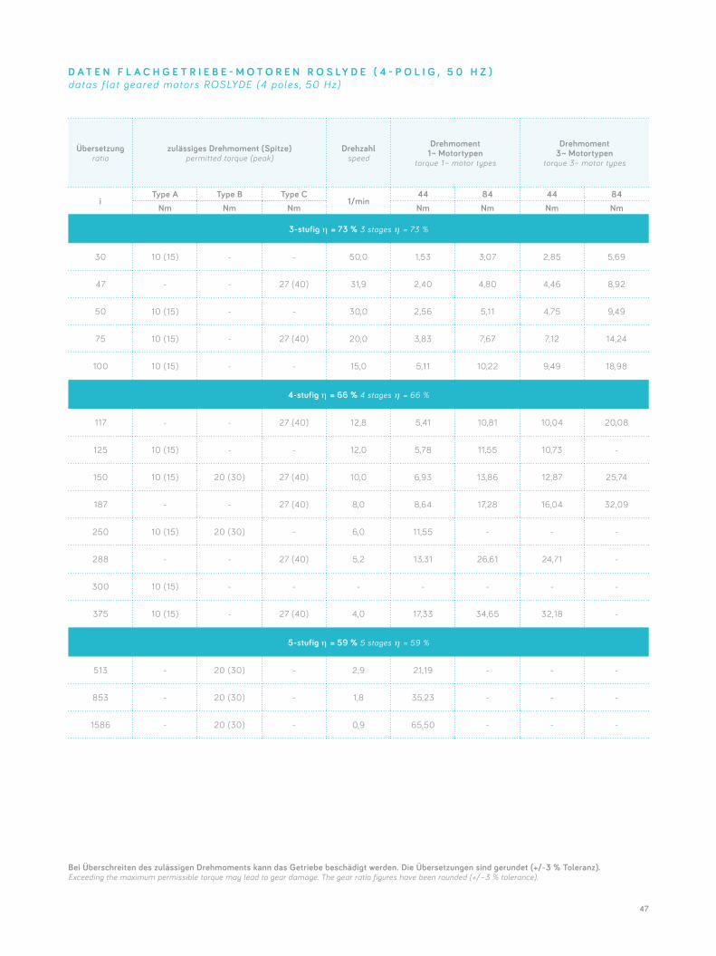
Übersetzungratio
zulässiges Drehmoment (Spitze)permitted torque (peak)
Drehzahlspeed
Drehmoment 1 ~ Motortypen
torque 1 ~ motor types
Drehmoment 3 ~ Motortypen
torque 3~ motor types
iType A Type B Type C
1/min44 84 44 84
Nm Nm Nm Nm Nm Nm Nm
3-stufig η = 73 % 3 stages η = 73 %
30 10 (15) - - 50,0 1,53 3,07 2,85 5,69
47 - - 27 (40) 31,9 2,40 4,80 4,46 8,92
50 10 (15) - - 30,0 2,56 5,11 4,75 9,49
75 10 (15) - 27 (40) 20,0 3,83 7,67 7,12 14,24
100 10 (15) - - 15,0 5,11 10,22 9,49 18,98
4-stufig η = 66 % 4 stages η = 66 %
117 - - 27 (40) 12,8 5,41 10,81 10,04 20,08
125 10 (15) - - 12,0 5,78 11,55 10,73 -
150 10 (15) 20 (30) 27 (40) 10,0 6,93 13,86 12,87 25,74
187 - - 27 (40) 8,0 8,64 17,28 16,04 32,09
250 10 (15) 20 (30) - 6,0 11,55 - - -
288 - - 27 (40) 5,2 13,31 26,61 24,71 -
300 10 (15) - - - - - - -
375 10 (15) - 27 (40) 4,0 17,33 34,65 32,18 -
5-stufig η = 59 % 5 stages η = 59 %
513 - 20 (30) - 2,9 21,19 - - -
853 - 20 (30) - 1,8 35,23 - - -
1586 - 20 (30) - 0,9 65,50 - - -
D A T E N F L A C H G E T R I E B E - M O T O R E N R O S L Y D E ( 4 - P O L I G , 5 0 H Z )datas f lat geared motors ROSLYDE (4 poles , 50 Hz)
Bei Überschreiten des zulässigen Drehmoments kann das Getriebe beschädigt werden. Die Übersetzungen sind gerundet (+/-3 % Toleranz). Exceeding the maximum permissible torque may lead to gear damage. The gear ratio figures have been rounded (+/–3 % tolerance).

ww
w.b
ra
ue
.in
fo
R O T E K G M B H & C O . K G
Coloradostraße 11+1327580 BremerhavenT E L + 49-471-984 09-0F A X + 49-471-984 09-29 M A I L [email protected] E B www.rotek-motoren.de
Das Vorhaben wurde aus Mitteln des Landes Bremen gefördert.
© 2018 Rotek GmbH & Co. KG Nachdruck nur mit schriftlicher Genehmigung.
Änderungen und Irrtum für den gesamten Inhalt vorbehalten. Reprinting only allowed if written permission has been obtained.
We reserve the right to make changes to any part of the above content and disclaim liability for any errors it may contain.