Embed Size (px)
Citation preview
1
Multi-Architecture Operating Systems
Ovidiu Dobre
Diplomarbeit
Verantwortlicher Betreuer: Prof. Dr. Alfred Schmitt Betreuende Mitarbeiter: Dipl.-Inf. Espen Skoglund
4 October 2004
Universität Karlsruhe (TH)
Institut für Betriebs- und Dialogsysteme Lehrstuhl Systemarchitektur

2

3
Hiermit erkläre ich, die vorliegende Arbeit selbständig verfasst und keine anderen als die angegebenen Literaturhilfsmittel verwendet zu haben. I hereby declare that this thesis is a work of my own, and that only cited sources have been used.
Karlsruhe, den 4. October 2004
Ovidiu Dobre

4
5
Abstract Requirements for high-performance computing have led hardware designers to construct multiprocessor systems using different processor architectures and thus providing best computing performance for a specific computing problem. The integration of different processor architectures is also employed in processor designs to offer compatibility for today’s mainstream processor architectures. Examples are the Itanium and the AMD-64 processors which offer compatibility for the IA-32 architecture. This trend in hardware technology needs to be supported by advances in software technology.
This thesis will attempt to provide design solutions for operating systems in tightly-coupled heterogeneous systems. The case study of an Itanium-based system will provide an answer concerning the suitability of the theoretical solution.
6
Acknowledgments
I would like to thank my supervisor Espen Skoglund for his expertise and patient support which made this work possible. In addition, I am thankful to all members of the System Architecture Group which constantly supported me all this time: Uwe Dannowski, Jens Doll, Sebastian Biemüller, Volkmar Uhlig, Joshua LeVasseur, Gerd Liefländer, Daniel Kirchner, Stefan Götz, Ulf Vatter, Christian Ceelen and Jan Stöß.
7
Contents
1 Introduction............................................................................... 9 1.1 Background ............................................................................................... 9
1.1.1 The case for heterogeneous computing.......................................... 9 1.1.2 Architectural compatibility ...........................................................10
1.2 Motivation and problem definition.........................................................10 1.3 Approach.................................................................................................. 11 1.4 Construction of the thesis........................................................................12
2 Related Work ............................................................................13 2.1 RACE: Heterogeneous Multicomputer System ......................................13 2.2 InterWeave: Shared State for Heterogeneous Distributed Systems......14 2.3 IA-32 support in IA-64 Linux .................................................................16
3 Design of Multi-Architecture Operating Systems (MA/OS) ........18 3.1 Computing systems .................................................................................18 3.2 SPMA computing systems ..................................................................... 20 3.3 MPMA computing systems .....................................................................21 3.4 Design models ........................................................................................ 23 3.5 User-level support for heterogeneity ..................................................... 24 3.6 Native and Secondary Architectures ..................................................... 25
3.6.1 Functional interface vs. Shared data............................................27 3.6.2 User-level vs. Kernel-level emulation......................................... 30 3.6.3 Top vs. Bottom Design .................................................................31
3.7 Equal opportunity .................................................................................. 33 3.7.1 Global data structures.................................................................. 34 3.7.2 Coherency mechanism .................................................................37
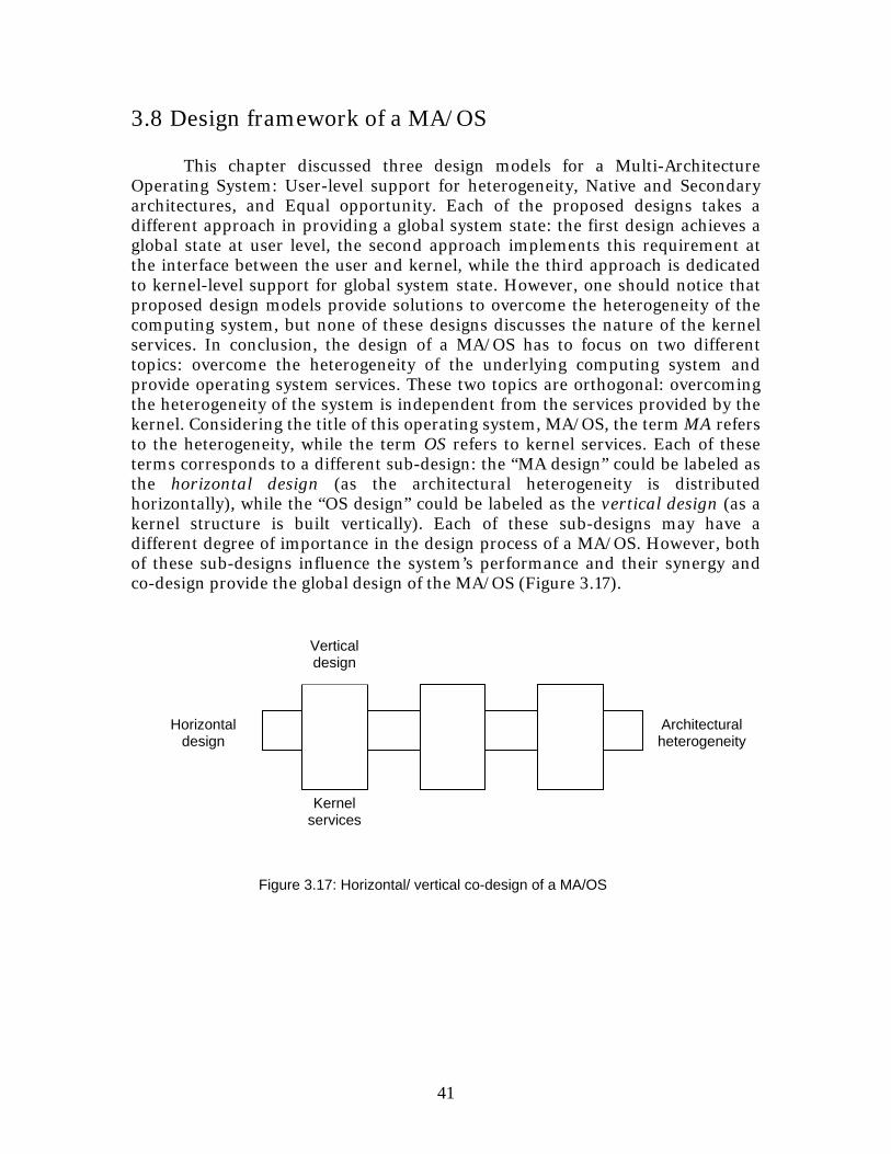
3.8 Design framework of a MA/OS...............................................................41

8
4 Case study of a MA/OS: L4 and Itanium.................................... 42 4.1 Motivation .............................................................................................. 42 4.2 Description of the experimental approach ............................................ 42 4.3 Support for IA-32 in Itanium processor................................................ 43
4.3.1 Support at IA-64 ISA Level ......................................................... 44 4.3.2 Support at Processor Level ......................................................... 46
4.4 Horizontal design: IA-32 emulation layer on an IA-64 kernel ............. 50 4.4.1 IA-32 Emulation Layer.................................................................51 4.4.2 IA-32 Exception Handling .......................................................... 53 4.4.3 IA-32 Memory Segmentation ..................................................... 54 4.4.4 Transition between IA-32 and IA-64...........................................55
4.5 Vertical design: L4Ka::Pistachio.............................................................57 4.6 Co-design process of the MA/OS........................................................... 58
4.6.1 IA-32 emulation layer in Pistachio IA-64 ................................... 59 4.6.2 IA-32 Exception Handling in Pistachio IA-64............................ 68 4.6.3 IA-32 Memory Segmentation in Pistachio IA-64....................... 69 4.6.4 Transition between IA-32 and IA-64 in Pistachio IA-64 ........... 69
5 Evaluation of the implementation ............................................ 70 5.1 Evaluation of design requirements ........................................................ 70 5.2 Performance of IA-32 threads ................................................................ 71
6 Analysis ....................................................................................77 6.1 Functionality vs. Performance ................................................................77 6.2 The microkernel approach..................................................................... 78 6.3 Linux based MA/OS................................................................................79
7 Conclusions and Future Work.................................................. 80 7.1 Summary................................................................................................. 80 7.2 Achievements ..........................................................................................81 7.3 Future work .............................................................................................81
8 Bibliography ............................................................................ 82
9
Chapter 1
Introduction This chapter presents the topic of this thesis. A background of the research area together with the considered approach is given.
1.1 Background
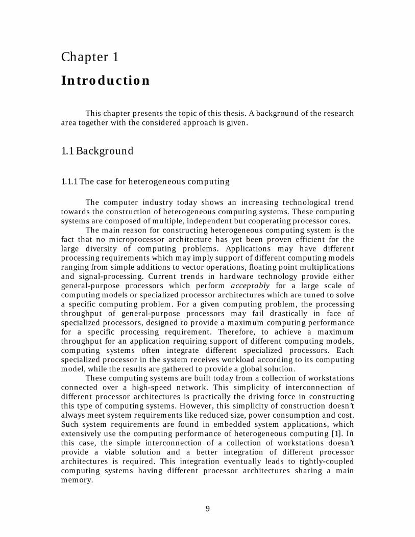
1.1.1 The case for heterogeneous computing
The computer industry today shows an increasing technological trend towards the construction of heterogeneous computing systems. These computing systems are composed of multiple, independent but cooperating processor cores.
The main reason for constructing heterogeneous computing system is the fact that no microprocessor architecture has yet been proven efficient for the large diversity of computing problems. Applications may have different processing requirements which may imply support of different computing models ranging from simple additions to vector operations, floating point multiplications and signal-processing. Current trends in hardware technology provide either general-purpose processors which perform acceptably for a large scale of computing models or specialized processor architectures which are tuned to solve a specific computing problem. For a given computing problem, the processing throughput of general-purpose processors may fail drastically in face of specialized processors, designed to provide a maximum computing performance for a specific processing requirement. Therefore, to achieve a maximum throughput for an application requiring support of different computing models, computing systems often integrate different specialized processors. Each specialized processor in the system receives workload according to its computing model, while the results are gathered to provide a global solution.
These computing systems are built today from a collection of workstations connected over a high-speed network. This simplicity of interconnection of different processor architectures is practically the driving force in constructing this type of computing systems. However, this simplicity of construction doesn’t always meet system requirements like reduced size, power consumption and cost. Such system requirements are found in embedded system applications, which extensively use the computing performance of heterogeneous computing [1]. In this case, the simple interconnection of a collection of workstations doesn’t provide a viable solution and a better integration of different processor architectures is required. This integration eventually leads to tightly-coupled computing systems having different processor architectures sharing a main memory.
10
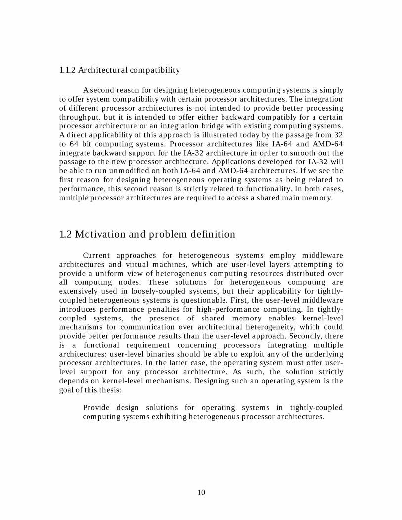
1.1.2 Architectural compatibility A second reason for designing heterogeneous computing systems is simply
to offer system compatibility with certain processor architectures. The integration of different processor architectures is not intended to provide better processing throughput, but it is intended to offer either backward compatibly for a certain processor architecture or an integration bridge with existing computing systems. A direct applicability of this approach is illustrated today by the passage from 32 to 64 bit computing systems. Processor architectures like IA-64 and AMD-64 integrate backward support for the IA-32 architecture in order to smooth out the passage to the new processor architecture. Applications developed for IA-32 will be able to run unmodified on both IA-64 and AMD-64 architectures. If we see the first reason for designing heterogeneous operating systems as being related to performance, this second reason is strictly related to functionality. In both cases, multiple processor architectures are required to access a shared main memory.
1.2 Motivation and problem definition
Current approaches for heterogeneous systems employ middleware architectures and virtual machines, which are user-level layers attempting to provide a uniform view of heterogeneous computing resources distributed over all computing nodes. These solutions for heterogeneous computing are extensively used in loosely-coupled systems, but their applicability for tightly-coupled heterogeneous systems is questionable. First, the user-level middleware introduces performance penalties for high-performance computing. In tightly-coupled systems, the presence of shared memory enables kernel-level mechanisms for communication over architectural heterogeneity, which could provide better performance results than the user-level approach. Secondly, there is a functional requirement concerning processors integrating multiple architectures: user-level binaries should be able to exploit any of the underlying processor architectures. In the latter case, the operating system must offer user-level support for any processor architecture. As such, the solution strictly depends on kernel-level mechanisms. Designing such an operating system is the goal of this thesis:
Provide design solutions for operating systems in tightly-coupled computing systems exhibiting heterogeneous processor architectures.
11
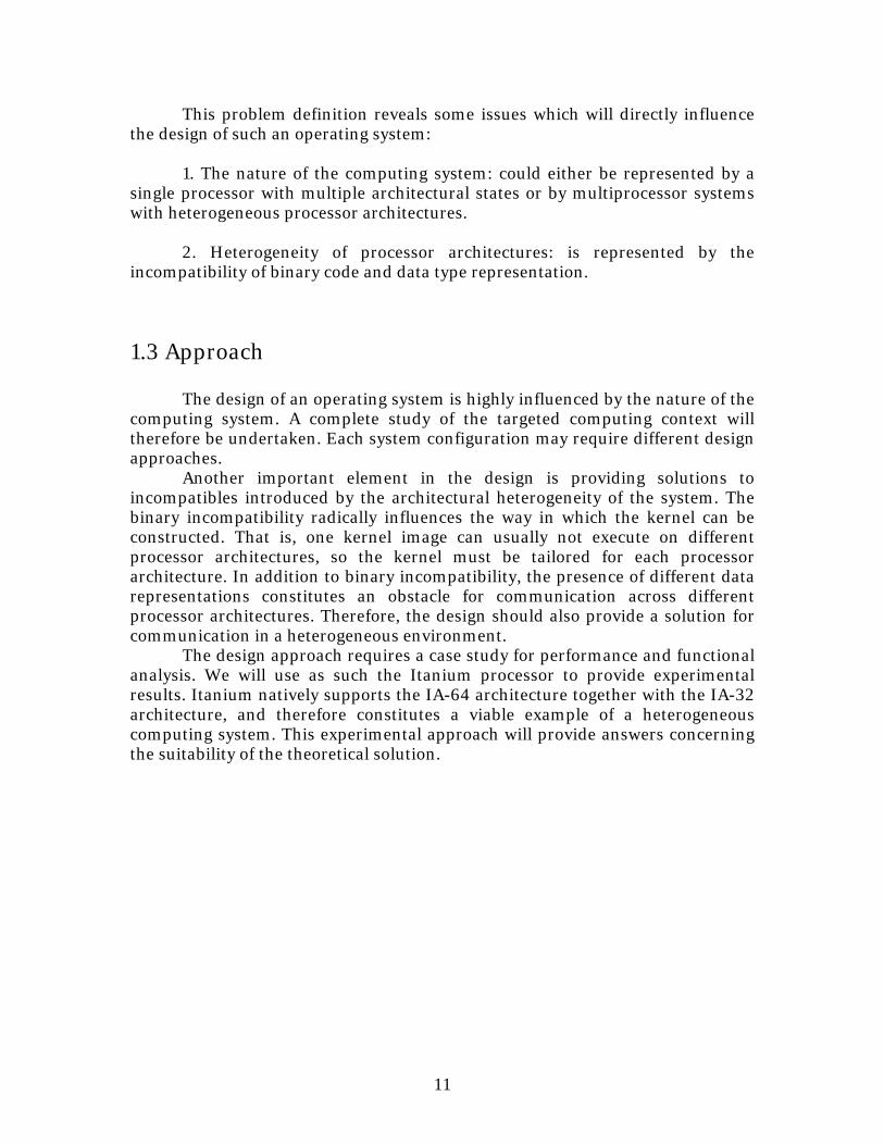
This problem definition reveals some issues which will directly influence the design of such an operating system:
1. The nature of the computing system: could either be represented by a
single processor with multiple architectural states or by multiprocessor systems with heterogeneous processor architectures.
2. Heterogeneity of processor architectures: is represented by the
incompatibility of binary code and data type representation.
1.3 Approach
The design of an operating system is highly influenced by the nature of the computing system. A complete study of the targeted computing context will therefore be undertaken. Each system configuration may require different design approaches.
Another important element in the design is providing solutions to incompatibles introduced by the architectural heterogeneity of the system. The binary incompatibility radically influences the way in which the kernel can be constructed. That is, one kernel image can usually not execute on different processor architectures, so the kernel must be tailored for each processor architecture. In addition to binary incompatibility, the presence of different data representations constitutes an obstacle for communication across different processor architectures. Therefore, the design should also provide a solution for communication in a heterogeneous environment. The design approach requires a case study for performance and functional analysis. We will use as such the Itanium processor to provide experimental results. Itanium natively supports the IA-64 architecture together with the IA-32 architecture, and therefore constitutes a viable example of a heterogeneous computing system. This experimental approach will provide answers concerning the suitability of the theoretical solution.
12
1.4 Construction of the thesis
The rest of the thesis is organized as follows: Chapter 2 - Discusses some of the main research trends in the field of the
heterogeneous computing and their possible implications on the topic of this thesis.
Chapter 3 - Presents the proposed solution. This solution will focus on
providing multiple design models, each with different applicability levels depending on the nature of the computing system. This proposed solution is only a theoretical approach without an experimental evaluation.
Chapter 4 - Discusses a case study of the proposed solution: Itanium
processor (IA-64 and IA-32) and L4 microkernel. The design of the operating system will be based on a design model which shows better applicability for this specific case study.
Chapter 5 – Presents the experimental evaluation of the operating
system design discussed in the previous chapter. Chapter 6 - Analyzes the suitability of the theoretical solution with
respect to the experimental results. Chapter 7 - Gives a recapitulation of the main issues discussed in this
thesis: motivation, proposed solution and experimental results. A final conclusion is drawn concerning the research topic of this thesis and directions for future work are proposed.
13
Chapter 2
Related Work
This chapter gives an overview of the main approaches in heterogeneous computing systems. The focus is set on two architectures which define the current trends in heterogeneous computing: the RACE architecture which provides a solution (hardware and software) for scalable heterogeneous computing systems and InterWeave, a middleware for shared state in distributed heterogeneous systems. Both architectures are based on multicomputer systems. An addition, this chapter presents an example of an operating system (IA-64 Linux) supporting binaries of two processor architectures, IA-32 and IA-64.
2.1 RACE: Heterogeneous Multicomputer System The RACE architecture [2] delivers a complete hardware-software solution for heterogeneous multicomputer systems. The hardware approach of RACE is not as relevant as the software approach for the research topic of this thesis, but it deserves at least an overview, mainly for its remarkable architecture in terms of modularity and scalability. The hardware architecture of RACE is composed of computing nodes, I/O nodes and connection fabric (connecting the nodes of the system either through bus architecture or switching network). Each computing node is composed of one or more processors of the same architecture, local DRAM memory and an ASIC1 providing a DMA controller (offering access at local memory to any other computing nodes) and address mapping logic (enabling the local processors to access any DRAM location in any remote computing node). Different computing nodes can have different architectures. In short, the hardware architecture is represented by heterogeneous computing nodes with local physical memory and a mechanism for memory access at any physical memory from any computing node in the system. Every memory location in the system can be accessed by any processor in the system, so a cache coherency problem could be raised. The problem of cache coherency has an efficient solution in this case due to physical distribution of memory: a computing node is concerned by cache coherency only in relationship with its own local memory. Whenever a processor either reads or writes data from/into a remote memory, each local processor sharing that memory invalidates the cache entry corresponding to the accessed data. This mechanism reduces drastically the amount of traffic for “snooping” memory
1 Application-Specific Integrated Circuit
14
addresses, as a processor has to watch only the local memory bus which is composed from a reduced number for processors (till three processors) comparing with the entire computing system. This solution for cache coherency provides data coherency for hardware-shared memory (accesses on same physical memory location), but it doesn’t solve software-shared memory coherency (information replicated on multiple computing nodes on different physical memories). The software-shared memory problem requires a software approach due to complexity of “bookkeeping” at hardware level of all the memory transactions on different computer nodes. Moreover, a software approach is better suited in this case as it can exploit the specific requirements of an application in terms of software-shared memory. The software approach for data coherency is usually implemented by a middleware layer. The question now concerns how the software architecture of RACE couples with the hardware architecture. The solution proposed by RACE is largely influenced by the modularity of the hardware architecture: each processor has its own single-processor operating system, completely independently from any other operating system running on remote computing nodes. This approach allows removal or insertion of computing nodes with no effect at kernel level for already existing operating system instances. As such, the kernel is not required to provide support for heterogeneous computing. Threads running on different computing nodes are independent, each having its own address space. There is however a mechanism implemented on top of this operating system which transparently handles the communication among computing nodes and the access on physical memory located on remote computing nodes. This mechanism enables software shared memory among remote threads. This software approach is the result of modularity of the hardware architecture which enforces modularity at operating software level. The physical distribution of the memory makes practically impossible to achieve a tightly-coupled operating system. The only suitable solution for this hardware design is a single-processor operating system per computing node with a user-level mechanism for inter-processor communication.
In conclusion, the RACE architecture provides a good design model of user-level support for heterogeneous computing.
2.2 InterWeave: Shared State for Heterogeneous Distributed Systems InterWeave is a middleware architecture for distributed shared state [3]. This architecture is designed to provide a distributed shared state in systems ranging from tightly coupled multiprocessor system to distributed heterogeneous systems spread around different geographical locations. As an alternative to message passing, InterWeave allows processes to share memory regions of their own address space across heterogeneous distributed computing nodes. This facility enables processes to share information
15
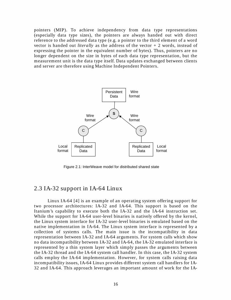
replicated around multiple locations with different data type representations. The shared information has a static structure (the structure of a replica doesn’t change upon creation), but its content can change over time. All mechanisms for providing data coherency among replicas are provided by the middleware. The coherency mechanism is based on the server-client model. Servers manage a persistent copy of the replicated data and provide this data whenever a client requests it. Each time a client is started and connects to the server, a copy of the data is sent by the server to the client. Whenever a client updates its local copy of shared data, these updates are forwarded to the server which takes care of updating its persistent copy of the replicated data. Any request following an update will receive data which reflects the current distributed state. The applicability of the centralized model is based on communication scalability between server and clients (to avoid a bottleneck by increasing number of clients), communication reliability (to avoid transmission of erroneous data) and server reliability (to avoid crashes which will bring the entire system down). This coherency model has different variations ranging from full coherency (always obtain the most recent version of data) to relaxed coherency (which accepts a difference between the delivered version and the persistent copy managed by the server, either considering a time difference of the local copy or a percentage of information out-of-date). An important aspect for this centralized coherency model is the connection scalability: when having many accesses on global shared data, low connection scalability may transform the server in a bottleneck. This risk increases its chances when the targeted coherency model is full coherency and each access on global shared data needs to be confirmed by the server. One important issue for a coherency mechanism is the protocol for delivering updates between clients and the server. InterWeave offers two concepts: polling and notifications. With pooling, the client regularly requests updates from the server. With notifications, the server has an active role of informing the client whenever an update on the client’s data is required. Another aspect of the update protocol is the granularity of the data to be updated and transferred: transfer only the modified regions of shared data or transfer the entire shared data. The choice for a certain approach depends on the size of the update compared to the size of the shared data and the frequency at which updates are performed. In addition to coherency mechanisms among distributed replicas, the InterWeave middleware provide mechanisms for exchanging data between computing nodes with heterogeneous data formats. The model proposed by InterWeave for exchanging data with heterogeneous representations is the model offered by all classical middleware systems like CORBA or .Net: conversion of data types from machine-specific format to a generic InterWeave format (“the wire format”). This generic format serves as exchange format between clients and the server (Figure 2.1). Another issue introduced by heterogeneity of data types is the usage of pointers on non-atomically shared data. Pointers to data types typically vary according to the size of data type representation (e.g. pointing to the next machine word value from a vector increases the pointer location with 4 bytes on 32 bit architectures and with 8 bytes on 64 bit architectures). Again this issue is solved by InterWeave by providing the concept of machine-independent
16
pointers (MIP). To achieve independency from data type representations (especially data type sizes), the pointers are always handed out with direct reference to the addressed data type (e.g. a pointer to the third element of a word vector is handed out literally as the address of the vector + 2 words, instead of expressing the pointer in the equivalent number of bytes). Thus, pointers are no longer dependent on the size in bytes of each data type representation, but the measurement unit is the data type itself. Data updates exchanged between clients and server are therefore using Machine Independent Pointers.
2.3 IA-32 support in IA-64 Linux Linux IA-64 [4] is an example of an operating system offering support for two processor architectures: IA-32 and IA-64. This support is based on the Itanium’s capability to execute both the IA-32 and the IA-64 instruction set. While the support for IA-64 user-level binaries is natively offered by the kernel, the Linux system interface for IA-32 user-level binaries is emulated based on the native implementation in IA-64. The Linux system interface is represented by a collection of systems calls. The main issue is the incompatibility in data representation between IA-32 and IA-64 arguments. For system calls which show no data incompatibility between IA-32 and IA-64, the IA-32 emulated interface is represented by a thin system layer which simply passes the arguments between the IA-32 thread and the IA-64 system call handler. In this case, the IA-32 system calls employ the IA-64 implementation. However, for system calls raising data incompatibility issues, IA-64 Linux provides different system call handlers for IA-32 and IA-64. This approach leverages an important amount of work for the IA-
Wire format
Local format
Wire format
Wire format
S
C C
Replicated Data
Persistent Data
Local format
Replicated Data
Figure 2.1: InterWeave model for distributed shared state
17
32 emulated interface. In addition to system call interface, the IA-32 support includes additional mechanisms: IA-32 memory model, IA-32 absolute file system paths, IA-32 signal delivering, management of the I/O port space, preservation of IA-32 architectural registers. In conclusion, IA-64 Linux provides an IA-32 execution environment which enables execution of heterogeneous applications composed of IA-32 and IA-64 binaries.
18
Chapter 3
Design of Multi-Architecture Operating Systems (MA/OS)
This chapter discusses the guidelines for designing a Multi-Architecture Operating System. We first study the nature of the computing systems requiring a MA/OS. Each of these computing systems will represent a base of discussion for the main design models of a MA/OS. In addition, a general approach for constructing this type of operating systems will be presented.
3.1 Computing systems
The first issue in designing an operating system is finding the targeted computing system. According to Flynn’s classification [5], computer systems can be divided in four classes based on the number of instruction and data streams. The classification doesn’t take the processor architecture into consideration. However, heterogeneous systems can generally fit in the case of MIMD (Multiple Instruction/Multiple Data Streams), as they exhibit multiple instruction streams with associated data streams due to architectural heterogeneity.
A classification of computer systems which does take the processor architecture into consideration was proposed in [6] and it constitutes a result from the field of heterogeneous computing. The classification of heterogeneous systems is based on two orthogonal concepts: the number of execution modes and the number of execution models. The execution mode is related to the type of parallelism supported by the machine (e.g. vector, SIMD, MIMD). This concept is independent of the execution model, which refers either to different architectural states of the machine or to different performance levels (e.g. different clock rates). We will concentrate on the number of architectural states exhibited by the computing system, as the incompatibilities between different architectural states influence directly the design of the kernel. As such, the classification provides two categories which fit to our targeted computing system: Single Execution Mode/Multiple Machine Model (SEMM) and Multiple Execution Mode/Multiple Machine Model (MEMM) with the remark that the interest on machine model is strictly related to heterogeneity of architectural states and not to the performance within the same architectural family.
However, from the point of view of an MA/OS, there exists an additional criterion which is not taken in consideration in any of these classifications: the number of architectural states per processor. This criterion has an important
19
impact on designing an MA/OS. We therefore propose a classification that takes into account the number of computing nodes (labeled as processors) and the number of architectural states. These two criteria are orthogonal: a processor can have multiple architectural states, while an architectural state can be supported on multiple processors. Based on these two criteria, computing systems can be classified in four classes:
1. SPSA (Single Processor/Single Architecture): a mono-processor system 2. SPMA (Single Processor/Multi-Architecture): a mono-processor with
multiple architectural states (e.g. Itanium, AMD-64) 3. MPSA (Multi-Processor/Single Architecture): a system composed of
multiple processors with the same architecture (e.g. current SMP or homogeneous distributed systems)
4. MPMA (Multi-Processor/Multi-Architecture): a system composed of multiple processors exhibiting multiple architectural states A MA/OS is exclusively related to multiple architectural states, so only two
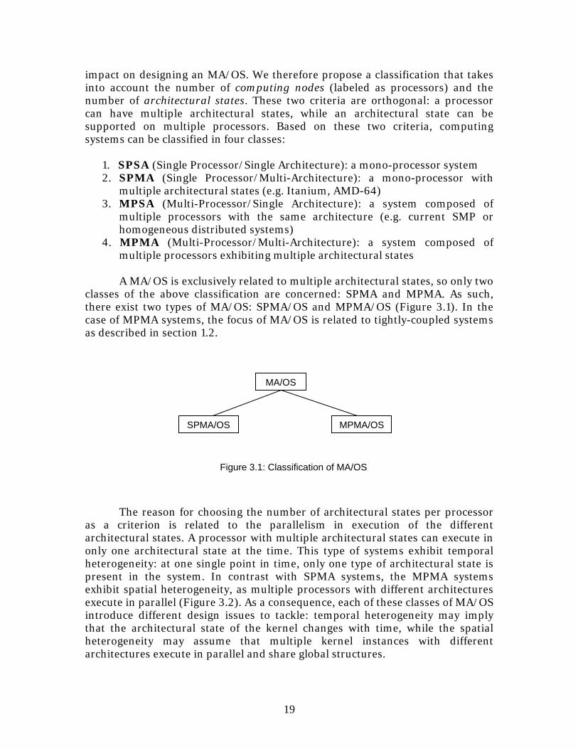
classes of the above classification are concerned: SPMA and MPMA. As such, there exist two types of MA/OS: SPMA/OS and MPMA/OS (Figure 3.1). In the case of MPMA systems, the focus of MA/OS is related to tightly-coupled systems as described in section 1.2.
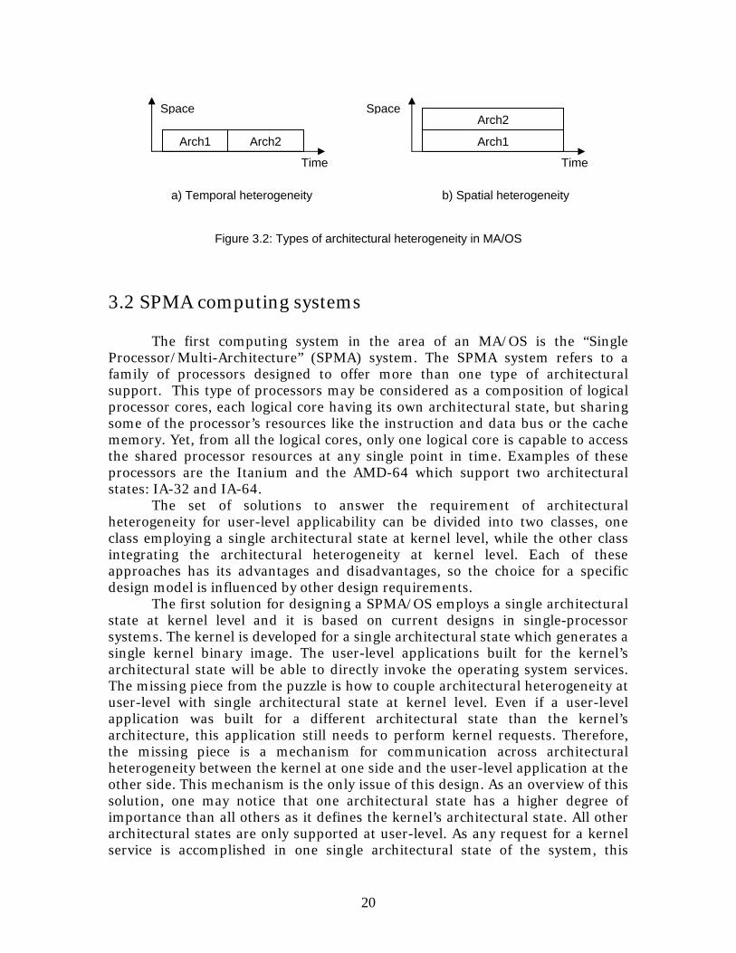
The reason for choosing the number of architectural states per processor as a criterion is related to the parallelism in execution of the different architectural states. A processor with multiple architectural states can execute in only one architectural state at the time. This type of systems exhibit temporal heterogeneity: at one single point in time, only one type of architectural state is present in the system. In contrast with SPMA systems, the MPMA systems exhibit spatial heterogeneity, as multiple processors with different architectures execute in parallel (Figure 3.2). As a consequence, each of these classes of MA/OS introduce different design issues to tackle: temporal heterogeneity may imply that the architectural state of the kernel changes with time, while the spatial heterogeneity may assume that multiple kernel instances with different architectures execute in parallel and share global structures.
MA/OS
SPMA/OS MPMA/OS
Figure 3.1: Classification of MA/OS
20
3.2 SPMA computing systems
The first computing system in the area of an MA/OS is the “Single Processor/Multi-Architecture” (SPMA) system. The SPMA system refers to a family of processors designed to offer more than one type of architectural support. This type of processors may be considered as a composition of logical processor cores, each logical core having its own architectural state, but sharing some of the processor’s resources like the instruction and data bus or the cache memory. Yet, from all the logical cores, only one logical core is capable to access the shared processor resources at any single point in time. Examples of these processors are the Itanium and the AMD-64 which support two architectural states: IA-32 and IA-64.
The set of solutions to answer the requirement of architectural heterogeneity for user-level applicability can be divided into two classes, one class employing a single architectural state at kernel level, while the other class integrating the architectural heterogeneity at kernel level. Each of these approaches has its advantages and disadvantages, so the choice for a specific design model is influenced by other design requirements.
The first solution for designing a SPMA/OS employs a single architectural state at kernel level and it is based on current designs in single-processor systems. The kernel is developed for a single architectural state which generates a single kernel binary image. The user-level applications built for the kernel’s architectural state will be able to directly invoke the operating system services. The missing piece from the puzzle is how to couple architectural heterogeneity at user-level with single architectural state at kernel level. Even if a user-level application was built for a different architectural state than the kernel’s architecture, this application still needs to perform kernel requests. Therefore, the missing piece is a mechanism for communication across architectural heterogeneity between the kernel at one side and the user-level application at the other side. This mechanism is the only issue of this design. As an overview of this solution, one may notice that one architectural state has a higher degree of importance than all others as it defines the kernel’s architectural state. All other architectural states are only supported at user-level. As any request for a kernel service is accomplished in one single architectural state of the system, this
SpaceSpace
Time Time
Arch1 Arch2
a) Temporal heterogeneity b) Spatial heterogeneity
Figure 3.2: Types of architectural heterogeneity in MA/OS
Arch1
Arch2
21
solution could also be modeled as a master-client approach: the kernel’s architectural state is the master architecture while all other architectures are client architectures. The master architecture provides services in behalf of client architectures. From the point of view of the operating system, the master architecture performs all critical operations (e.g. kernel’s system calls, exception handling) while client architectures serve only to execute non-critical operations (e.g. user-level binaries). From the user’s perspective, this design approach could be regarded as native and secondary architectures.
The second design approach for a SPMA/OS employs architectural heterogeneity at kernel level. This design approach raises an important issue as any single machine binary cannot execute on multiple architectural states due to binary incompatibility. Therefore the binary code of the kernel has to be split up between architectural states. One acceptable solution is to provide a homogeneous kernel structure in term of architectural state and to implement this kernel structure for multiple architectural states. In this way, the binary incompatibility is solved by providing a kernel instance per each architectural state exhibited by the processor. Each kernel instance can provide kernel services to user-level applications built for the same architectural state. This design approach apparently solves the initial issue: provide architectural heterogeneity at user-level. Each user-level application can request kernel services as the operating system provides a kernel instance built for each architectural state exhibited by the system. The question now is how to construct such a single operating system image based on a set of architectural-dependent kernel instances. Looking at the first design approach of a SPMA/OS, the design issue was the interface point between the user’s requirement for architectural heterogeneity and the kernel approach for single architectural state. The main issue of the second design approach is the interface at kernel level among multiple kernel instances. The second design approach can be labeled as an equal opportunity model: critical operations for the operating system can be performed in any architectural state by the appropriate kernel instance.
In conclusion, there are two main design approaches for SMPA operating systems. Both approaches still have an internal issue which will be discussed further in this chapter.
3.3 MPMA computing systems
The second computing system in the area of MA/OS is the “Multi-Processor/Multi-Architecture” (MPMA) system. The term “MPMA” refers to multi-processor systems composed of processors with heterogeneous architectures connected through a system bus and sharing the main memory. Processors in such a hardware configuration are able to perform concurrent accesses on main memory which generate data coherency issues at cache level and require in addition exclusion mechanisms on shared data structures. These issues are the main research topic of SMP (Symmetric MultiProcessor) systems and solutions are either provided at hardware level (cache coherency protocols)
22
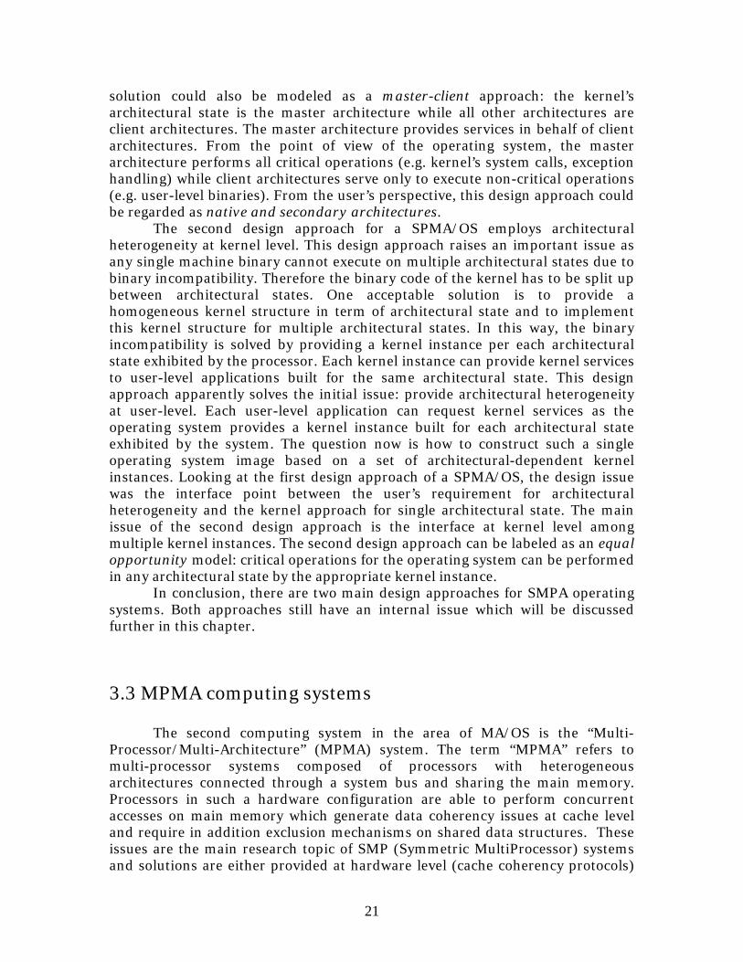
or at kernel level (exclusion mechanisms on shared data structures). The defining property of SMP systems is the homogeneous architecture of internal processors. This approach allows a smooth hardware coupling of processors on the shared memory bus and provides the ability of running the same kernel image on all processors based on same architectural state. The MPMA systems introduce an important difference with SMP systems in tightly-coupled multiprocessor systems, namely the architectural heterogeneity of processors sharing the main memory. These computing systems are labeled as exhibiting spatial heterogeneity (Figure 3.3).
As for SPMA/OS, the essential design requirement for such an operating
system is to provide architectural heterogeneity for user-level applications. In other words, the operating system must provide the capability to develop applications which exploit the architectural heterogeneity of the underlying system (e.g. run threads of a given task on different processor architectures depending on their computational requirements). The first design approach found for SMPA operating systems we labeled as native and secondary architectures: a single architecture serves for kernel implementation, while all other architectures are only supported at user-level. This approach doesn’t fit well with the execution parallelism of MPMA systems. Translated to MPMA systems, this design approach defines a certain processor (master processor) which runs the kernel of the operating system, while all other processors (client processors) are supposed to run only user-level binaries. Of course, the interaction between the user-level binaries and the kernel cannot longer be treated through an architectural switch, since it basically requires passing a request from one processor (running the user-level binary) to another processor (running the kernel). The second design approach suitable for SPMA systems was labeled as equal opportunities: there is a different kernel instance per each architectural state. At first sight, this design approach is more suitable for MPMA systems than the previous one as the spatial heterogeneity of the kernel fits with the spatial heterogeneity of the computing system. Therefore, each processor runs its own kernel image and user-level binaries running on top of these kernel instances can simply access the kernel services without the problem of architectural
Processor Arch 2
System Bus
Figure 3.3: Architecture of a MPMA system
Processor Arch 1 Main
Memory Cache Cache
23
heterogeneity or the need for an inter-processor communication. The design issues don’t stop here as the user-level applications should be able to take advantage of the architectural heterogeneity of the systems. If there is no mechanism for interaction between the kernel instances, the user-level applications will only be mono-architectural, without possibility of solving problems requiring heterogeneous computing. Two solutions providing support for inter-kernel cooperation can be envisaged: a user-level approach and a kernel-level approach. The former approach employs middleware architectures: a user-level layer providing cooperation between heterogeneous applications. A kernel instance can have no or limited knowledge of the existence of other kernel instances. As a consequence, the kernel instances are practically independent one from another and thus they are not required to obey the same design structure. The latter approach requires implementing the inter-kernel cooperation at kernel level. This solution is suitable when the operating system should provide transparency for any architectural state. In addition, this approach is probably more challenging than the former one in terms of kernel design as it requires synchronization and coherency mechanism to achieve cooperation at kernel level.
3.4 Design models The SPMA and MPMA systems show the same design models for the kernel structure. These design approaches could be divided in three classes:
1. User-level support for heterogeneity: Each architectural state has its own kernel instance independent from each other; support for architectural heterogeneity is implemented at user-level
2. Native and secondary architectures: A single architectural state is considered for the kernel design; support for
architectural heterogeneity is implemented at kernel-level 3. Equal opportunity Each architectural state has its own kernel instance, while sharing a global
state; support for architectural heterogeneity is implemented at kernel-level
These classes show different approaches in designing a MA/OS. The essential requirement is support for architectural heterogeneity for user-level applications. This requirement could be fulfilled either by taking into account the architectural heterogeneity of the system at kernel level (design 2 and 3) or by implementing this support at user level (design 1). The latter case has a limited influence on the kernel’s design. The next sections will elaborate on these design approaches.
24
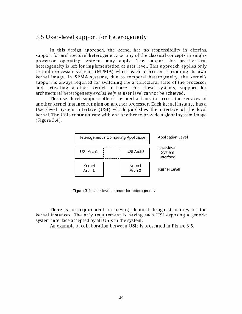
3.5 User-level support for heterogeneity In this design approach, the kernel has no responsibility in offering support for architectural heterogeneity, so any of the classical concepts in single-processor operating systems may apply. The support for architectural heterogeneity is left for implementation at user level. This approach applies only to multiprocessor systems (MPMA) where each processor is running its own kernel image. In SPMA systems, due to temporal heterogeneity, the kernel’s support is always required for switching the architectural state of the processor and activating another kernel instance. For these systems, support for architectural heterogeneity exclusively at user level cannot be achieved. The user-level support offers the mechanisms to access the services of another kernel instance running on another processor. Each kernel instance has a User-level System Interface (USI) which publishes the interface of the local kernel. The USIs communicate with one another to provide a global system image (Figure 3.4).
There is no requirement on having identical design structures for the kernel instances. The only requirement is having each USI exposing a generic system interface accepted by all USIs in the system.
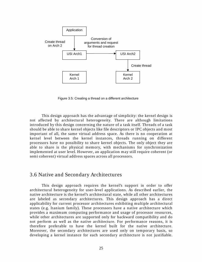
An example of collaboration between USIs is presented in Figure 3.5.
Kernel Arch 2
Kernel Arch 1
USI Arch1 USI Arch2
Heterogeneous Computing Application
Figure 3.4: User-level support for heterogeneity
User-level System
Interface
Application Level
Kernel Level
25
This design approach has the advantage of simplicity: the kernel design is not affected by architectural heterogeneity. There are although limitations introduced by this design concerning the nature of a task itself. Threads of a task should be able to share kernel objects like file descriptors or IPC objects and most important of all, the same virtual address space. As there is no cooperation at kernel level between the kernel instances, threads running on different processors have no possibility to share kernel objects. The only object they are able to share is the physical memory, with mechanisms for synchronization implemented at user level. However, an application may still require coherent (or semi coherent) virtual address spaces across all processors.
3.6 Native and Secondary Architectures
This design approach requires the kernel’s support in order to offer architectural heterogeneity for user-level applications. As described earlier, the native architecture is the kernel’s architectural state, while all other architectures are labeled as secondary architectures. This design approach has a direct applicability for current processor architectures exhibiting multiple architectural states (e.g. Itanium family). These processors have a native architecture which provides a maximum computing performance and usage of processor resources, while other architectures are supported only for backward compatibility and do not perform as well as the native architecture. For performance reasons, it is therefore preferable to have the kernel built for the native architecture. Moreover, the secondary architectures are used only on temporary basis, so developing a kernel instance for each secondary architecture is not justifiable.
Conversion of arguments and request
for thread creation
Create thread
Kernel Arch 2
Kernel Arch 1
USI Arch1 USI Arch2
Application
Figure 3.5: Creating a thread on a different architecture
Create thread on Arch 2
26
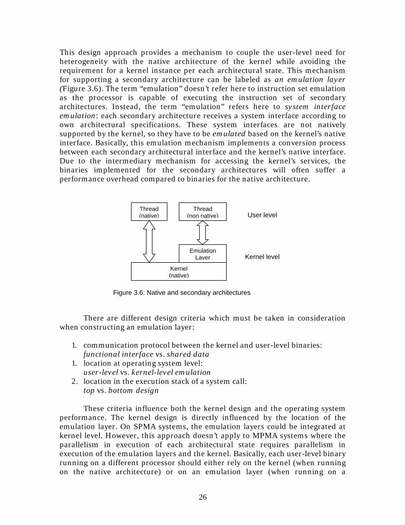
This design approach provides a mechanism to couple the user-level need for heterogeneity with the native architecture of the kernel while avoiding the requirement for a kernel instance per each architectural state. This mechanism for supporting a secondary architecture can be labeled as an emulation layer (Figure 3.6). The term “emulation” doesn’t refer here to instruction set emulation as the processor is capable of executing the instruction set of secondary architectures. Instead, the term “emulation” refers here to system interface emulation: each secondary architecture receives a system interface according to own architectural specifications. These system interfaces are not natively supported by the kernel, so they have to be emulated based on the kernel’s native interface. Basically, this emulation mechanism implements a conversion process between each secondary architectural interface and the kernel’s native interface. Due to the intermediary mechanism for accessing the kernel’s services, the binaries implemented for the secondary architectures will often suffer a performance overhead compared to binaries for the native architecture.
There are different design criteria which must be taken in consideration
when constructing an emulation layer: 1. communication protocol between the kernel and user-level binaries:
functional interface vs. shared data 1. location at operating system level:
user-level vs. kernel-level emulation 2. location in the execution stack of a system call:
top vs. bottom design These criteria influence both the kernel design and the operating system performance. The kernel design is directly influenced by the location of the emulation layer. On SPMA systems, the emulation layers could be integrated at kernel level. However, this approach doesn’t apply to MPMA systems where the parallelism in execution of each architectural state requires parallelism in execution of the emulation layers and the kernel. Basically, each user-level binary running on a different processor should either rely on the kernel (when running on the native architecture) or on an emulation layer (when running on a
Kernel (native)
Emulation Layer
Figure 3.6: Native and secondary architectures
Thread (non native)
Thread (native)
Kernel level
User level
27
secondary architecture). Therefore, the MPMA systems accept only user-level emulation layers with a “spatial” decoupling from the kernel. When integrated at kernel level in SPMA systems, an emulation layer may take into consideration another design criterion: whether the native kernel should be aware of the presence of the emulation layer or not. In the former approach, the emulation layer sits on top of the kernel proper and filters communication between user-level binary and the kernel without the kernel noticing its presence. In the latter approach, the kernel has to acknowledge the presence of the emulation layer and to invoke its mechanisms when communicating with user-level binaries of secondary architectures. Another criterion which may influence the design approach for an emulation layer is whether the communication between user-level binaries and the emulation layer is synchronous (functional interface) or asynchronous (shared memory). The advantages and disadvantages of these strategies are discussed further in the following section. However, there is no ideal design model for such an emulation layer and the choices for specific strategies are depending on specific design requirements for the operating system.
3.6.1 Functional interface vs. Shared data
This criterion refers to the nature of the communication protocol between the user-level binaries and the kernel. The communication protocol depends strictly on the specific system interface according to each architectural state. Even if the kernel provides its own native interface, system interfaces for other architectural states may have different specifications concerning the communication protocol. Commonly speaking, each architectural state should have structurally the same system interface as the native kernel if they rely on the same kernel architecture. However, this might not be always the case and the emulation layer should consider the appropriate communication protocol in relationship with user-level binaries.
Generally speaking, the system interface may either be composed of a functional interface (system call interface) or shared kernel-user data structures. Each of these communication strategies has its own advantages and disadvantages.
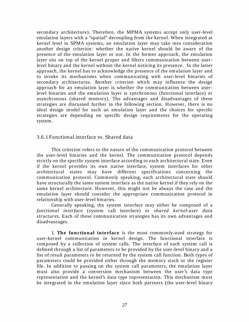
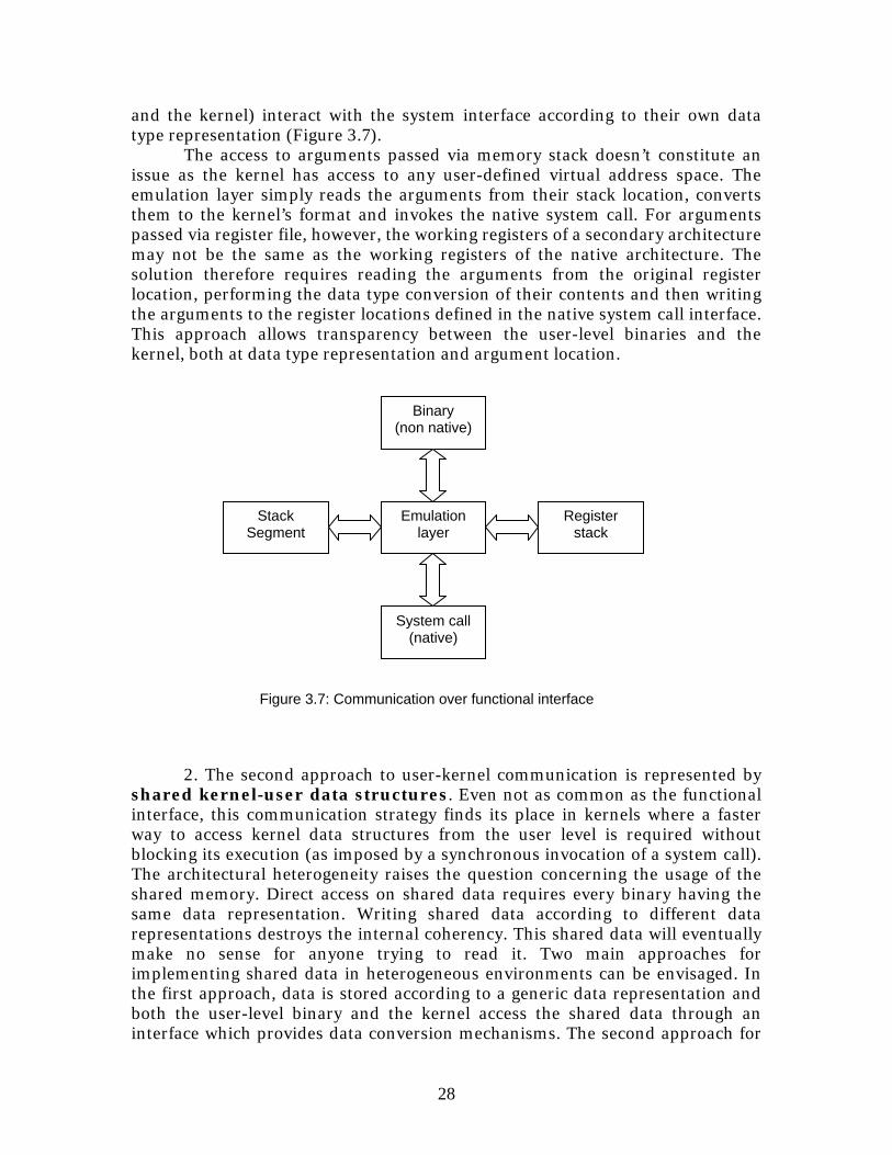
1. The functional interface is the most commonly-used strategy for user-kernel communication in kernel design. The functional interface is composed by a collection of system calls. The interface of each system call is defined through a list of parameters to be provided by the user-level binary and a list of result parameters to be returned by the system call function. Both types of parameters could be provided either through the memory stack or the register file. In addition to passing on the system call parameters, the emulation layer must also provide a conversion mechanism between the user’s data type representation and the kernel’s data type representation. This mechanism must be integrated in the emulation layer since both partners (the user-level binary
28
and the kernel) interact with the system interface according to their own data type representation (Figure 3.7).
The access to arguments passed via memory stack doesn’t constitute an issue as the kernel has access to any user-defined virtual address space. The emulation layer simply reads the arguments from their stack location, converts them to the kernel’s format and invokes the native system call. For arguments passed via register file, however, the working registers of a secondary architecture may not be the same as the working registers of the native architecture. The solution therefore requires reading the arguments from the original register location, performing the data type conversion of their contents and then writing the arguments to the register locations defined in the native system call interface. This approach allows transparency between the user-level binaries and the kernel, both at data type representation and argument location.
2. The second approach to user-kernel communication is represented by
shared kernel-user data structures. Even not as common as the functional interface, this communication strategy finds its place in kernels where a faster way to access kernel data structures from the user level is required without blocking its execution (as imposed by a synchronous invocation of a system call). The architectural heterogeneity raises the question concerning the usage of the shared memory. Direct access on shared data requires every binary having the same data representation. Writing shared data according to different data representations destroys the internal coherency. This shared data will eventually make no sense for anyone trying to read it. Two main approaches for implementing shared data in heterogeneous environments can be envisaged. In the first approach, data is stored according to a generic data representation and both the user-level binary and the kernel access the shared data through an interface which provides data conversion mechanisms. The second approach for
System call (native)
Stack Segment
Emulation layer
Register stack
Binary (non native)
Figure 3.7: Communication over functional interface
29
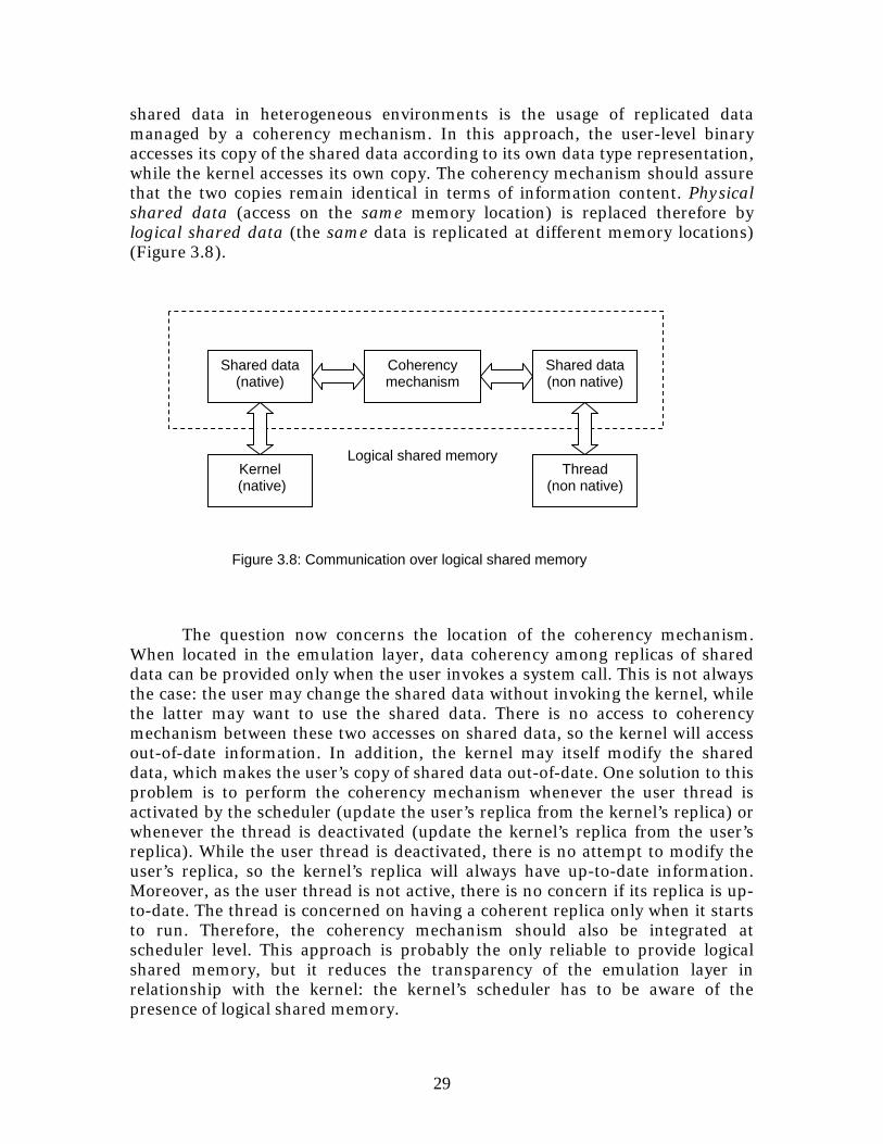
shared data in heterogeneous environments is the usage of replicated data managed by a coherency mechanism. In this approach, the user-level binary accesses its copy of the shared data according to its own data type representation, while the kernel accesses its own copy. The coherency mechanism should assure that the two copies remain identical in terms of information content. Physical shared data (access on the same memory location) is replaced therefore by logical shared data (the same data is replicated at different memory locations) (Figure 3.8).
The question now concerns the location of the coherency mechanism.
When located in the emulation layer, data coherency among replicas of shared data can be provided only when the user invokes a system call. This is not always the case: the user may change the shared data without invoking the kernel, while the latter may want to use the shared data. There is no access to coherency mechanism between these two accesses on shared data, so the kernel will access out-of-date information. In addition, the kernel may itself modify the shared data, which makes the user’s copy of shared data out-of-date. One solution to this problem is to perform the coherency mechanism whenever the user thread is activated by the scheduler (update the user’s replica from the kernel’s replica) or whenever the thread is deactivated (update the kernel’s replica from the user’s replica). While the user thread is deactivated, there is no attempt to modify the user’s replica, so the kernel’s replica will always have up-to-date information. Moreover, as the user thread is not active, there is no concern if its replica is up-to-date. The thread is concerned on having a coherent replica only when it starts to run. Therefore, the coherency mechanism should also be integrated at scheduler level. This approach is probably the only reliable to provide logical shared memory, but it reduces the transparency of the emulation layer in relationship with the kernel: the kernel’s scheduler has to be aware of the presence of logical shared memory.
Kernel (native)
Coherency mechanism
Thread (non native)
Figure 3.8: Communication over logical shared memory
Shared data (native)
Shared data (non native)
Logical shared memory
30
Another issue for implementing logical shared memory concerns the update protocol of replicated copies: full or partial coherency. The general case is to offer access to the entire content of shared data and thus replicas have to contain the same information. There are alternatives when there is no need for full coherency (e.g. the shared memory is composed of multiple buffers and only of subset of these buffers are required at a certain access on shared data). In such cases, providing full coherency only induces a performance overhead. Therefore, a partial coherency mechanism may be implemented, in which coherency is provided only for those portions of the replicated data required at the moment of the access.
3.6.2 User-level vs. Kernel-level emulation
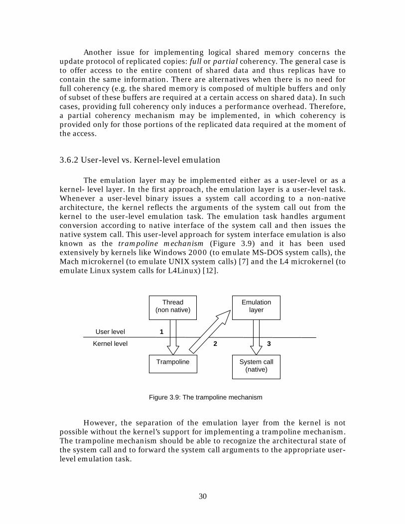
The emulation layer may be implemented either as a user-level or as a kernel- level layer. In the first approach, the emulation layer is a user-level task. Whenever a user-level binary issues a system call according to a non-native architecture, the kernel reflects the arguments of the system call out from the kernel to the user-level emulation task. The emulation task handles argument conversion according to native interface of the system call and then issues the native system call. This user-level approach for system interface emulation is also known as the trampoline mechanism (Figure 3.9) and it has been used extensively by kernels like Windows 2000 (to emulate MS-DOS system calls), the Mach microkernel (to emulate UNIX system calls) [7] and the L4 microkernel (to emulate Linux system calls for L4Linux) [12].
However, the separation of the emulation layer from the kernel is not possible without the kernel’s support for implementing a trampoline mechanism. The trampoline mechanism should be able to recognize the architectural state of the system call and to forward the system call arguments to the appropriate user-level emulation task.
32
1User level
Kernel level
Trampoline System call (native)
Thread (non native)
Figure 3.9: The trampoline mechanism
Emulation layer
31
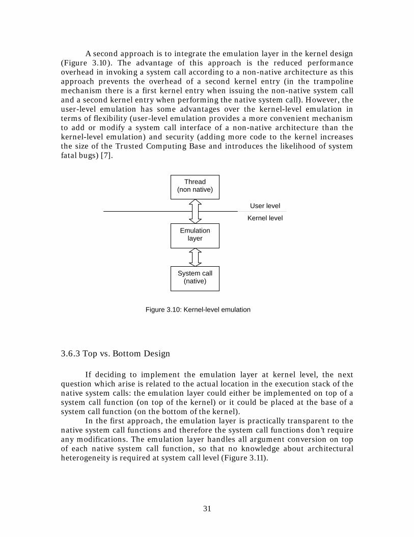
A second approach is to integrate the emulation layer in the kernel design (Figure 3.10). The advantage of this approach is the reduced performance overhead in invoking a system call according to a non-native architecture as this approach prevents the overhead of a second kernel entry (in the trampoline mechanism there is a first kernel entry when issuing the non-native system call and a second kernel entry when performing the native system call). However, the user-level emulation has some advantages over the kernel-level emulation in terms of flexibility (user-level emulation provides a more convenient mechanism to add or modify a system call interface of a non-native architecture than the kernel-level emulation) and security (adding more code to the kernel increases the size of the Trusted Computing Base and introduces the likelihood of system fatal bugs) [7].
3.6.3 Top vs. Bottom Design If deciding to implement the emulation layer at kernel level, the next question which arise is related to the actual location in the execution stack of the native system calls: the emulation layer could either be implemented on top of a system call function (on top of the kernel) or it could be placed at the base of a system call function (on the bottom of the kernel).
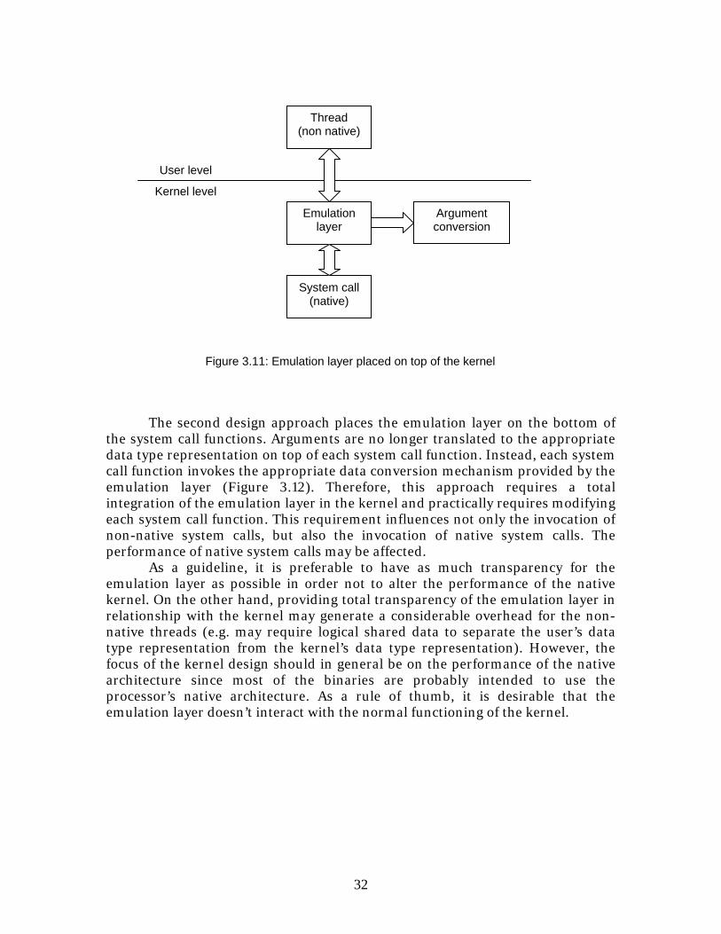
In the first approach, the emulation layer is practically transparent to the native system call functions and therefore the system call functions don’t require any modifications. The emulation layer handles all argument conversion on top of each native system call function, so that no knowledge about architectural heterogeneity is required at system call level (Figure 3.11).
Kernel level
Emulation layer
System call (native)
Thread (non native)
User level
Figure 3.10: Kernel-level emulation
32
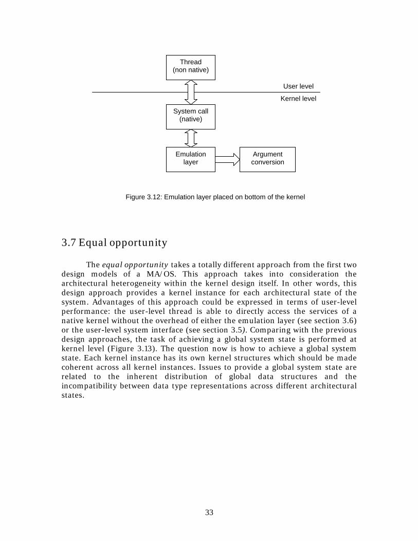
The second design approach places the emulation layer on the bottom of the system call functions. Arguments are no longer translated to the appropriate data type representation on top of each system call function. Instead, each system call function invokes the appropriate data conversion mechanism provided by the emulation layer (Figure 3.12). Therefore, this approach requires a total integration of the emulation layer in the kernel and practically requires modifying each system call function. This requirement influences not only the invocation of non-native system calls, but also the invocation of native system calls. The performance of native system calls may be affected.
As a guideline, it is preferable to have as much transparency for the emulation layer as possible in order not to alter the performance of the native kernel. On the other hand, providing total transparency of the emulation layer in relationship with the kernel may generate a considerable overhead for the non-native threads (e.g. may require logical shared data to separate the user’s data type representation from the kernel’s data type representation). However, the focus of the kernel design should in general be on the performance of the native architecture since most of the binaries are probably intended to use the processor’s native architecture. As a rule of thumb, it is desirable that the emulation layer doesn’t interact with the normal functioning of the kernel.
Kernel level
User level
Emulation layer
System call(native)
Thread (non native)
Figure 3.11: Emulation layer placed on top of the kernel
Argument conversion
33
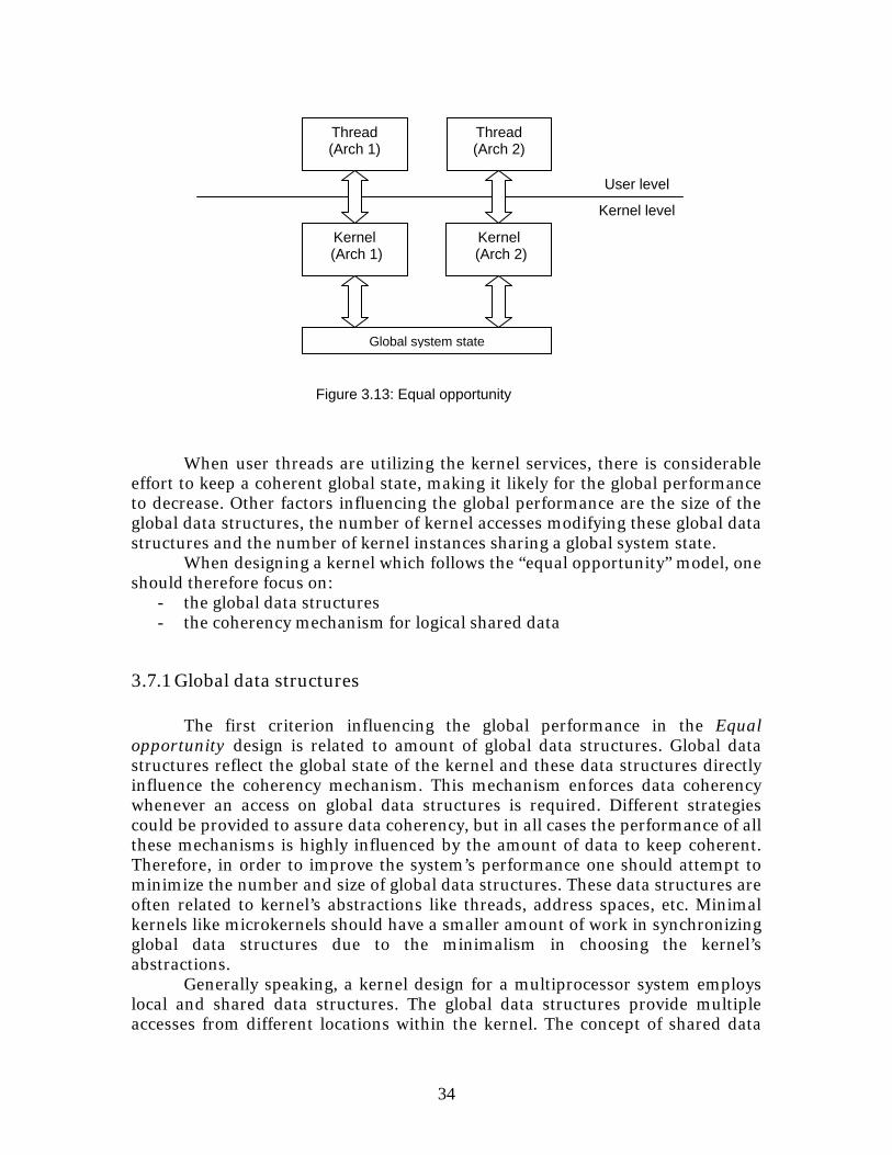
3.7 Equal opportunity The equal opportunity takes a totally different approach from the first two design models of a MA/OS. This approach takes into consideration the architectural heterogeneity within the kernel design itself. In other words, this design approach provides a kernel instance for each architectural state of the system. Advantages of this approach could be expressed in terms of user-level performance: the user-level thread is able to directly access the services of a native kernel without the overhead of either the emulation layer (see section 3.6) or the user-level system interface (see section 3.5). Comparing with the previous design approaches, the task of achieving a global system state is performed at kernel level (Figure 3.13). The question now is how to achieve a global system state. Each kernel instance has its own kernel structures which should be made coherent across all kernel instances. Issues to provide a global system state are related to the inherent distribution of global data structures and the incompatibility between data type representations across different architectural states.
Kernel level
User level
Emulation layer
System call (native)
Thread (non native)
Figure 3.12: Emulation layer placed on bottom of the kernel
Argument conversion
34
When user threads are utilizing the kernel services, there is considerable
effort to keep a coherent global state, making it likely for the global performance to decrease. Other factors influencing the global performance are the size of the global data structures, the number of kernel accesses modifying these global data structures and the number of kernel instances sharing a global system state. When designing a kernel which follows the “equal opportunity” model, one should therefore focus on:
- the global data structures - the coherency mechanism for logical shared data
3.7.1 Global data structures The first criterion influencing the global performance in the Equal
opportunity design is related to amount of global data structures. Global data structures reflect the global state of the kernel and these data structures directly influence the coherency mechanism. This mechanism enforces data coherency whenever an access on global data structures is required. Different strategies could be provided to assure data coherency, but in all cases the performance of all these mechanisms is highly influenced by the amount of data to keep coherent. Therefore, in order to improve the system’s performance one should attempt to minimize the number and size of global data structures. These data structures are often related to kernel’s abstractions like threads, address spaces, etc. Minimal kernels like microkernels should have a smaller amount of work in synchronizing global data structures due to the minimalism in choosing the kernel’s abstractions.
Generally speaking, a kernel design for a multiprocessor system employs local and shared data structures. The global data structures provide multiple accesses from different locations within the kernel. The concept of shared data
Kernel level
Kernel (Arch 1)
Kernel (Arch 2)
Figure 3.13: Equal opportunity
Thread (Arch 1)
Thread (Arch 2)
Global system state
User level
35
has a problem fitting in heterogeneous multiprocessor systems due to incompatibility between data type representations. Two different strategies may be envisaged for implementing shared data in a MA/OS:
- Global data representation (together with data conversion mechanisms for
accesses according to other data type representations) - Multiple data representations (together with a coherency mechanism for
implementing logical shared data)
1. Global data representation: A single data representation is selected. Any data structure with global semantics will be encoded using the global data representation. Whenever there is an access to global data using another data representation, a mechanism is invoked to provide the right data format. This strategy implies direct data access for architectural states having the global data representation, while accesses having other data type representations can access the global data only indirectly, through an interface which provides data conversion. Of course, the interface access induces a performance overhead for any architectural state not having the global data representation. The important question is therefore which data type representation to use as the global one. This choice could be based on different performance criteria: frequency of operations on global data structures with a certain data type representation (e.g. a certain data type representation is dominant), facility of data conversion between a particular data representation and all other available data representations (e.g. a certain data type representation is the extension of all others), etc. After selecting the global data type representation, data conversion mechanisms from the global to all other data representations are required. These mechanisms are embedded in each access interface according to the specific data type representation handled by the interface.
2. Multiple data representations: This strategy allows direct access to
global data using different data type representations. The key element of this solution is replication of data. This replication process requires a suitable coherency mechanism. The data conversion mechanisms between different data type representations will be integrated in the coherency mechanism.
Each data representation strategy has its own advantages and disadvantages, so the choice is strictly based on specific performance criteria. Based on these two strategies for implementing shared data in a MA/OS, each kernel data structure could be associated with one of the following classes:
1. Exclusive resources: This class is represented by resources with no
global semantics. Exclusive resources are represented by local data structures with no global semantics and by the architectural state (e.g. registers, trap and fault exceptions, software interrupts). These resources
36
are employed either with local or with architectural scope and thus they have no effect on the global state of the MA/OS.
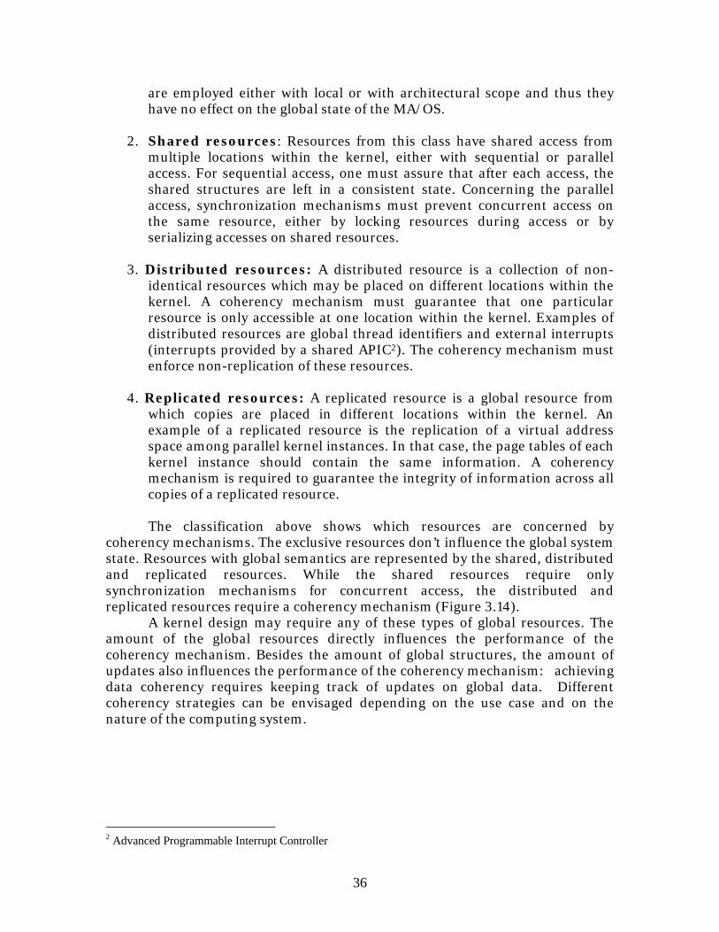
2. Shared resources: Resources from this class have shared access from
multiple locations within the kernel, either with sequential or parallel access. For sequential access, one must assure that after each access, the shared structures are left in a consistent state. Concerning the parallel access, synchronization mechanisms must prevent concurrent access on the same resource, either by locking resources during access or by serializing accesses on shared resources.
3. Distributed resources: A distributed resource is a collection of non-
identical resources which may be placed on different locations within the kernel. A coherency mechanism must guarantee that one particular resource is only accessible at one location within the kernel. Examples of distributed resources are global thread identifiers and external interrupts (interrupts provided by a shared APIC2). The coherency mechanism must enforce non-replication of these resources.
4. Replicated resources: A replicated resource is a global resource from
which copies are placed in different locations within the kernel. An example of a replicated resource is the replication of a virtual address space among parallel kernel instances. In that case, the page tables of each kernel instance should contain the same information. A coherency mechanism is required to guarantee the integrity of information across all copies of a replicated resource.
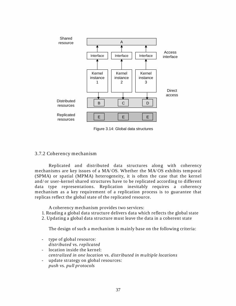
The classification above shows which resources are concerned by
coherency mechanisms. The exclusive resources don’t influence the global system state. Resources with global semantics are represented by the shared, distributed and replicated resources. While the shared resources require only synchronization mechanisms for concurrent access, the distributed and replicated resources require a coherency mechanism (Figure 3.14).
A kernel design may require any of these types of global resources. The amount of the global resources directly influences the performance of the coherency mechanism. Besides the amount of global structures, the amount of updates also influences the performance of the coherency mechanism: achieving data coherency requires keeping track of updates on global data. Different coherency strategies can be envisaged depending on the use case and on the nature of the computing system.
2 Advanced Programmable Interrupt Controller
37
3.7.2 Coherency mechanism
Replicated and distributed data structures along with coherency mechanisms are key issues of a MA/OS. Whether the MA/OS exhibits temporal (SPMA) or spatial (MPMA) heterogeneity, it is often the case that the kernel and/or user-kernel shared structures have to be replicated according to different data type representations. Replication inevitably requires a coherency mechanism as a key requirement of a replication process is to guarantee that replicas reflect the global state of the replicated resource.
A coherency mechanism provides two services:
1. Reading a global data structure delivers data which reflects the global state 2. Updating a global data structure must leave the data in a coherent state
The design of such a mechanism is mainly base on the following criteria:
- type of global resource: distributed vs. replicated
- location inside the kernel: centralized in one location vs. distributed in multiple locations
- update strategy on global resources: push vs. pull protocols
B C D
E E E
Kernel instance
1
Kernel instance
2
Kernel instance
3
Figure 3.14: Global data structures
Distributed resources
Replicated resources
Interface
A
Interface Interface
Shared resource
Access interface
Direct access
38
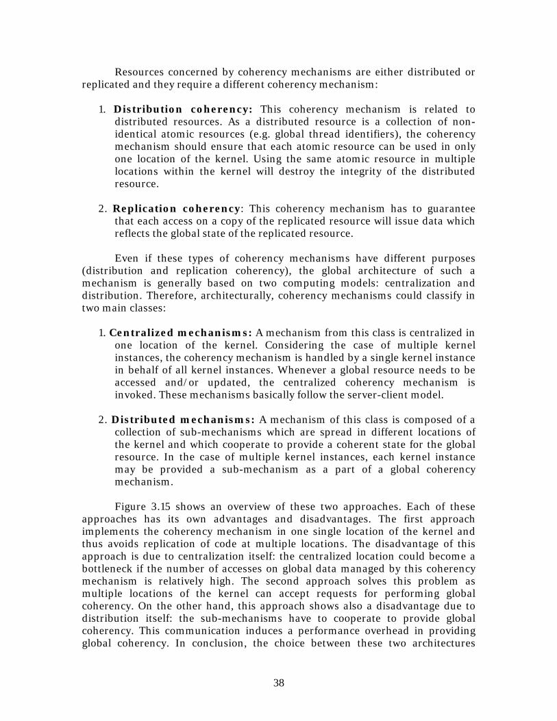
Resources concerned by coherency mechanisms are either distributed or replicated and they require a different coherency mechanism:
1. Distribution coherency: This coherency mechanism is related to
distributed resources. As a distributed resource is a collection of non-identical atomic resources (e.g. global thread identifiers), the coherency mechanism should ensure that each atomic resource can be used in only one location of the kernel. Using the same atomic resource in multiple locations within the kernel will destroy the integrity of the distributed resource.
2. Replication coherency: This coherency mechanism has to guarantee
that each access on a copy of the replicated resource will issue data which reflects the global state of the replicated resource.
Even if these types of coherency mechanisms have different purposes
(distribution and replication coherency), the global architecture of such a mechanism is generally based on two computing models: centralization and distribution. Therefore, architecturally, coherency mechanisms could classify in two main classes:
1. Centralized mechanisms: A mechanism from this class is centralized in
one location of the kernel. Considering the case of multiple kernel instances, the coherency mechanism is handled by a single kernel instance in behalf of all kernel instances. Whenever a global resource needs to be accessed and/or updated, the centralized coherency mechanism is invoked. These mechanisms basically follow the server-client model.
2. Distributed mechanisms: A mechanism of this class is composed of a
collection of sub-mechanisms which are spread in different locations of the kernel and which cooperate to provide a coherent state for the global resource. In the case of multiple kernel instances, each kernel instance may be provided a sub-mechanism as a part of a global coherency mechanism.
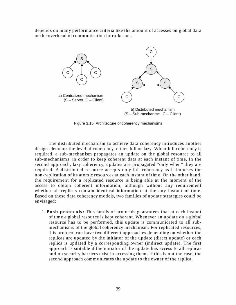
Figure 3.15 shows an overview of these two approaches. Each of these
approaches has its own advantages and disadvantages. The first approach implements the coherency mechanism in one single location of the kernel and thus avoids replication of code at multiple locations. The disadvantage of this approach is due to centralization itself: the centralized location could become a bottleneck if the number of accesses on global data managed by this coherency mechanism is relatively high. The second approach solves this problem as multiple locations of the kernel can accept requests for performing global coherency. On the other hand, this approach shows also a disadvantage due to distribution itself: the sub-mechanisms have to cooperate to provide global coherency. This communication induces a performance overhead in providing global coherency. In conclusion, the choice between these two architectures
39
depends on many performance criteria like the amount of accesses on global data or the overhead of communication intra-kernel.
The distributed mechanism to achieve data coherency introduces another
design element: the level of coherency, either full or lazy. When full coherency is required, a sub-mechanism propagates an update on the global resource to all sub-mechanisms, in order to keep coherent data at each instant of time. In the second approach, lazy coherency, updates are propagated “only when” they are required. A distributed resource accepts only full coherency as it imposes the non-replication of its atomic resources at each instant of time. On the other hand, the requirement for a replicated resource is being able at the moment of the access to obtain coherent information, although without any requirement whether all replicas contain identical information at the any instant of time. Based on these data coherency models, two families of update strategies could be envisaged:
1. Push protocols: This family of protocols guarantees that at each instant
of time a global resource is kept coherent. Whenever an update on a global resource has to be performed, this update is communicated to all sub-mechanisms of the global coherency mechanism. For replicated resources, this protocol can have two different approaches depending on whether the replicas are updated by the initiator of the update (direct update) or each replica is updated by a corresponding owner (indirect update). The first approach is suitable if the initiator of the update has access to all replicas and no security barriers exist in accessing them. If this is not the case, the second approach communicates the update to the owner of the replica.
S
C CS
S S
C C
C
C
a) Centralized mechanism (S – Server, C – Client)
b) Distributed mechanism (S – Sub-mechanism, C – Client)
Figure 3.15: Architecture of coherency mechanisms
40
2. Pull protocols: This family of protocols is suitable only for replicated resources. These protocols don’t guarantee that at each instant of time all replicas contain the same information, but instead they provide a mechanism to achieve coherency whenever the replicated resource is accessed. Thus, each update is performed only on the local copy and thus assuring that the local copy has the up-to-date information. Whenever data is accessed again, information from all replicas is requested to verify if whether the local copy still has up-to-date information or whether another copy was in the meanwhile updated. If the local copy contains out-of-date information, the up-to-date information is requested from another replica. This protocol has also two approaches depending on whether the requester accesses directly the other replicas (direct access) or it delegates the owner of each replica to deliver the information required (indirect access). In addition, this family of update protocols has another criterion to take in consideration: the atomicity of the replicated resource. If a replicated resource is not atomic and the information of the local replica is not required entirely at the moment of the access, one may choose to update only the required information in the local copy.
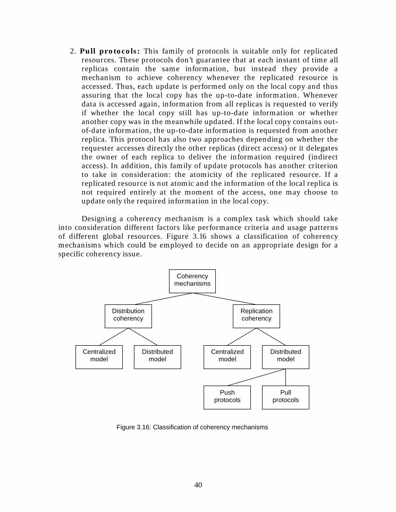
Designing a coherency mechanism is a complex task which should take
into consideration different factors like performance criteria and usage patterns of different global resources. Figure 3.16 shows a classification of coherency mechanisms which could be employed to decide on an appropriate design for a specific coherency issue.
Coherency mechanisms
Distribution coherency
Replication coherency
Centralized model
Distributed model
Centralized model
Distributed model
Push protocols
Pull protocols
Figure 3.16: Classification of coherency mechanisms
41
3.8 Design framework of a MA/OS This chapter discussed three design models for a Multi-Architecture Operating System: User-level support for heterogeneity, Native and Secondary architectures, and Equal opportunity. Each of the proposed designs takes a different approach in providing a global system state: the first design achieves a global state at user level, the second approach implements this requirement at the interface between the user and kernel, while the third approach is dedicated to kernel-level support for global system state. However, one should notice that proposed design models provide solutions to overcome the heterogeneity of the computing system, but none of these designs discusses the nature of the kernel services. In conclusion, the design of a MA/OS has to focus on two different topics: overcome the heterogeneity of the underlying computing system and provide operating system services. These two topics are orthogonal: overcoming the heterogeneity of the system is independent from the services provided by the kernel. Considering the title of this operating system, MA/OS, the term MA refers to the heterogeneity, while the term OS refers to kernel services. Each of these terms corresponds to a different sub-design: the “MA design” could be labeled as the horizontal design (as the architectural heterogeneity is distributed horizontally), while the “OS design” could be labeled as the vertical design (as a kernel structure is built vertically). Each of these sub-designs may have a different degree of importance in the design process of a MA/OS. However, both of these sub-designs influence the system’s performance and their synergy and co-design provide the global design of the MA/OS (Figure 3.17).
Architectural heterogeneity
Kernel services
Horizontal design
Vertical design
Figure 3.17: Horizontal/ vertical co-design of a MA/OS
42
Chapter 4
Case study of a MA/OS: L4 and Itanium This chapter presents an example on how to design a MA/OS. This case study is based on the Itanium processor (as a SPMA system) and the L4 microkernel (as the base design for the kernel). This study will attempt to verify the applicability of design models discussed in the previous chapter. The operating system design, together with the implementation and the experimental results will provide a way to effectively analyze the theoretical design model.
4.1 Motivation There are reasons to believe that a microkernel architecture as L4 can deliver best performance for a MA/OS design. This hypothesis is basically based on the architectural minimalism of a microkernel design which provides a small amount of system calls and kernel abstractions. As described in the previous chapter, the design of a MA/OS is composed of two orthogonal sub-designs: the horizontal design which handles the architectural heterogeneity and the vertical design which provides the kernel services. The microkernel design constitutes the vertical design of the MA/OS, while the choice for a horizontal design decides practically the performance of the global MA/OS. The integration of the microkernel in a MA/OS design may have an impact on its performance. The implementation provides an experimental evaluation of the effective performance of a microkernel based MA/OS.
4.2 Description of the experimental approach
A convenient experimental scenario consists in choosing a SPMA system (a processor with multiple architectural states). The choice was settled for an Itanium I processor which exhibits two architectural states, IA-64 and IA-32. Concerning the horizontal design, the “Native and Secondary Architectures” represents the most reasonable design for an Itanium-based system. The main reason for choosing this design is the difference in performance levels offered by Itanium for its architectural states: the IA-64 performs considerably better compared with IA-32. Therefore, the kernel of the system should be built on the native architecture (IA-64), while the IA-32 should be considered as a secondary architecture. The vertical design will be represented by the L4Ka::Pistachio.
The MA/OS is the synergy between the horizontal and the vertical design. This synergy requires implementing in the IA-64 version of Pistachio (vertical design) an emulation layer for IA-32 architectural state (horizontal design). The
43
general issues for integrating an IA-32 emulation layer in an IA-64 kernel will be discussed previously from studying the L4Ka::Pistachio design. These general issues will represent the discussion base for building an IA-32 emulation layer in Pistachio. The final outcome of this case study will be the experimental analysis regarding the performance of the MA/OS compared with the original design of Pistachio. This comparison will help understand how the performance of microkernel design is influenced by integrating it in a MA/OS and whether the eventual losses in performance are acceptable enough for constructing such an operating system.
4.3 Support for IA-32 in Itanium processor The first step in the design process of the operating system is an evaluation of the targeted computing system. Itanium qualifies as a SPMA (Single Processor/Multi-Architectures) system as it provides two architectural states, IA-64 and IA-32. The IA-64 is the native architectural state and provides best performance and usage of processor resources, while IA-32 provides a lower performance and is able to exploit only a reduced subset of Itanium’s resources (e.g. registers, address space). An interesting question concerns the reasons for integrating a second architectural state which doesn’t perform as well as native architectural state. The IA-64 was intended as a candidate for the next processor architecture following the today’s mainstream architecture, the IA-32. The IA-64 is definitely a more powerful architecture than the IA-32, but this fact is balanced by having the IA-32 practically running most of the applications intended for personal computing. Porting these applications for the new IA-64 architecture should be primarily justified by economical factors: is this gain in computing power balanced by the costs in porting these applications? The IA-64 designers have probably considered this scenario and it was clear that the introduction of IA-64 will not be such a smooth process. The decision was to integrate backward compatibility for IA-32 architecture in the new IA-64 architecture. As such, a migration process from IA-32 to IA-64 could be easily envisaged: first the IA-32 hardware should migrate to IA-64 while running the same IA-32 applications. Afterwards the applications are incrementally ported to IA-64 as soon as software distributors decide migrating their products. The IA-32 is supported at two levels:
1. IA-64 ISA Level: Provides a mechanism for switching between IA-32 and IA-64
2. Processor Level: Provides the hardware implementation of IA-32 architectural state
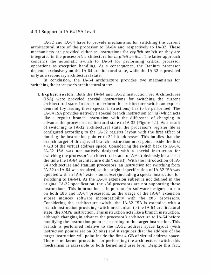
44
4.3.1 Support at IA-64 ISA Level
IA-32 and IA-64 have to provide mechanisms for switching the current architectural state of the processor to IA-64 and respectively to IA-32. These mechanisms are provided either as instructions for explicit switch or they are integrated in the processor’s architecture for implicit switch. The latter approach concerns the automatic switch to IA-64 for performing critical processor operations as exception handling. As a consequence, the Itanium processor depends exclusively on the IA-64 architectural state, while the IA-32 is provided only as a secondary architectural state.
In conclusion, the IA-64 architecture provides two mechanisms for switching the processor’s architectural state:
1. Explicit switch: Both the IA-64 and IA-32 Instruction Set Architectures (ISA) were provided special instructions for switching the current architectural state. In order to perform the architecture switch, an explicit demand (by issuing these special instructions) has to be performed. The IA-64 ISA provides natively a special branch instruction (br.ia) which acts like a regular branch instruction with the difference of changing in advance the processor architectural state to IA-32 (Figure 4.1). As a result of switching to IA-32 architectural state, the processor’s register file is configured according to the IA-32 register layout with the first effect of limiting the instruction pointer to 32 bit addresses. This implies that the branch target of this special branch instruction must point inside the first 4 GB of the virtual address space. Considering the switch back to IA-64, IA-32 ISA was not natively designed with a special instruction for switching the processor’s architectural state to IA-64 (obviously because at the time the IA-64 architecture didn’t exist!). With the introduction of IA-64 architecture and Itanium processors, an instruction for switching from IA-32 to IA-64 was required, so the original specification of IA-32 ISA was updated with an IA-64 extension subset (including a special instruction for switching to IA-64). As the IA-64 extension subset is not defined in the original IA-32 specification, the x86 processors are not supporting these instructions. This information is important for software designed to run on both x86 and IA-64 processors, as the usage of the IA-64 extension subset induces software incompatibility with the x86 processors. Considering the architecture switch, the IA-32 ISA is extended with a branch instruction providing switch mechanism to the IA-64 architectural state: the JMPE instruction. This instruction acts like a branch instruction, although changing in advance the processor’s architecture to IA-64 before modifying the instruction pointer according to the target instruction. This branch is performed relative to the IA-32 address space layout (with instruction pointer set on 32 bits) and it requires that the address of the target instruction will point inside the first 4 GB of virtual address space. There is no kernel protection for performing the architecture switch: this mechanism is accessible to both kernel and user level. Despite this fact,
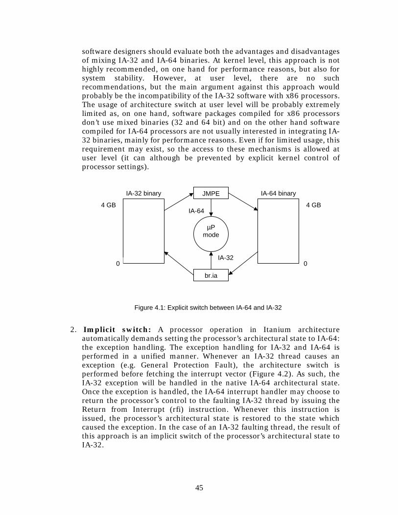
45
software designers should evaluate both the advantages and disadvantages of mixing IA-32 and IA-64 binaries. At kernel level, this approach is not highly recommended, on one hand for performance reasons, but also for system stability. However, at user level, there are no such recommendations, but the main argument against this approach would probably be the incompatibility of the IA-32 software with x86 processors. The usage of architecture switch at user level will be probably extremely limited as, on one hand, software packages compiled for x86 processors don’t use mixed binaries (32 and 64 bit) and on the other hand software compiled for IA-64 processors are not usually interested in integrating IA-32 binaries, mainly for performance reasons. Even if for limited usage, this requirement may exist, so the access to these mechanisms is allowed at user level (it can although be prevented by explicit kernel control of processor settings).
2. Implicit switch: A processor operation in Itanium architecture
automatically demands setting the processor’s architectural state to IA-64: the exception handling. The exception handling for IA-32 and IA-64 is performed in a unified manner. Whenever an IA-32 thread causes an exception (e.g. General Protection Fault), the architecture switch is performed before fetching the interrupt vector (Figure 4.2). As such, the IA-32 exception will be handled in the native IA-64 architectural state. Once the exception is handled, the IA-64 interrupt handler may choose to return the processor’s control to the faulting IA-32 thread by issuing the Return from Interrupt (rfi) instruction. Whenever this instruction is issued, the processor’s architectural state is restored to the state which caused the exception. In the case of an IA-32 faulting thread, the result of this approach is an implicit switch of the processor’s architectural state to IA-32.
IA-64 binary
4 GB
0
4 GB
IA-32 binary
IA-32
IA-64
Figure 4.1: Explicit switch between IA-64 and IA-32
µP mode
JMPE
br.ia
0
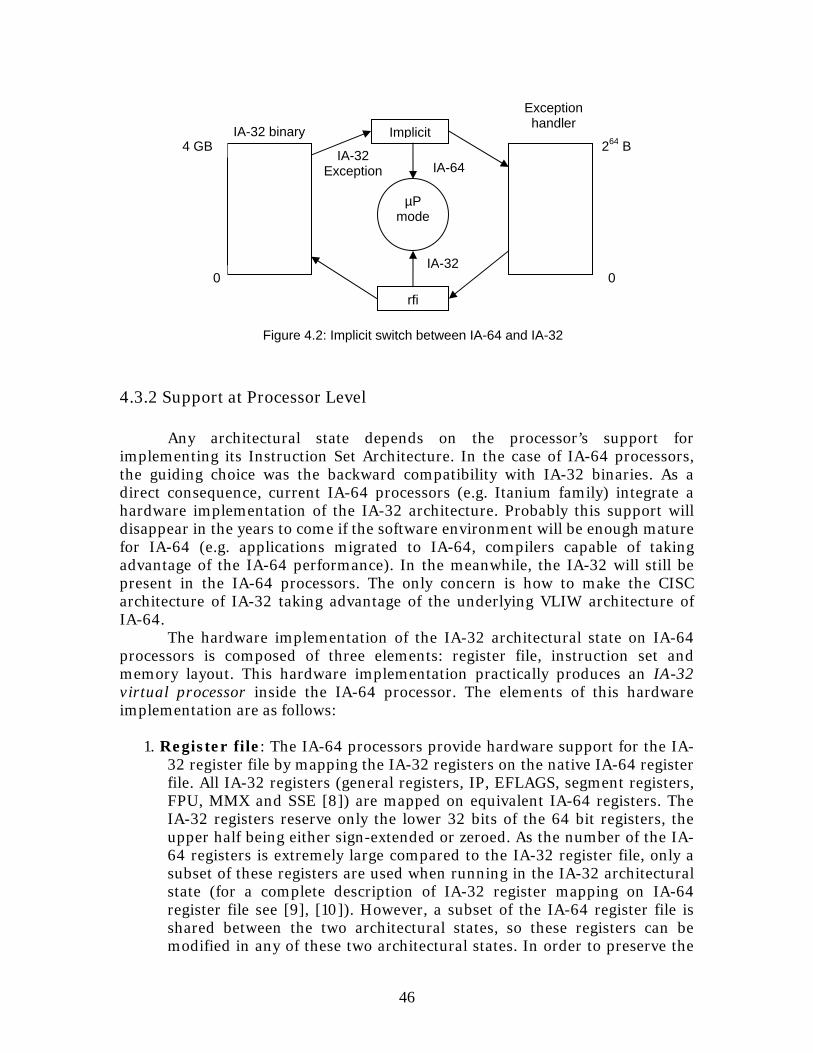
46
Exception handler
264 B IA-32 binary
IA-32 Exception
Figure 4.2: Implicit switch between IA-64 and IA-32
IA-32
IA-64
µP mode
Implicit
rfi0
4 GB
0
4.3.2 Support at Processor Level
Any architectural state depends on the processor’s support for implementing its Instruction Set Architecture. In the case of IA-64 processors, the guiding choice was the backward compatibility with IA-32 binaries. As a direct consequence, current IA-64 processors (e.g. Itanium family) integrate a hardware implementation of the IA-32 architecture. Probably this support will disappear in the years to come if the software environment will be enough mature for IA-64 (e.g. applications migrated to IA-64, compilers capable of taking advantage of the IA-64 performance). In the meanwhile, the IA-32 will still be present in the IA-64 processors. The only concern is how to make the CISC architecture of IA-32 taking advantage of the underlying VLIW architecture of IA-64.
The hardware implementation of the IA-32 architectural state on IA-64 processors is composed of three elements: register file, instruction set and memory layout. This hardware implementation practically produces an IA-32 virtual processor inside the IA-64 processor. The elements of this hardware implementation are as follows:
1. Register file: The IA-64 processors provide hardware support for the IA-32 register file by mapping the IA-32 registers on the native IA-64 register file. All IA-32 registers (general registers, IP, EFLAGS, segment registers, FPU, MMX and SSE [8]) are mapped on equivalent IA-64 registers. The IA-32 registers reserve only the lower 32 bits of the 64 bit registers, the upper half being either sign-extended or zeroed. As the number of the IA-64 registers is extremely large compared to the IA-32 register file, only a subset of these registers are used when running in the IA-32 architectural state (for a complete description of IA-32 register mapping on IA-64 register file see [9], [10]). However, a subset of the IA-64 register file is shared between the two architectural states, so these registers can be modified in any of these two architectural states. In order to preserve the
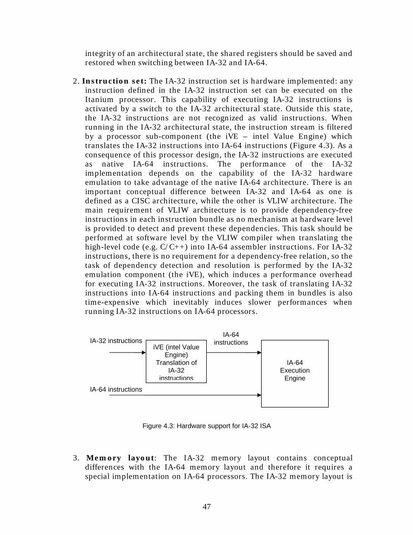
47
integrity of an architectural state, the shared registers should be saved and restored when switching between IA-32 and IA-64.
2. Instruction set: The IA-32 instruction set is hardware implemented: any instruction defined in the IA-32 instruction set can be executed on the Itanium processor. This capability of executing IA-32 instructions is activated by a switch to the IA-32 architectural state. Outside this state, the IA-32 instructions are not recognized as valid instructions. When running in the IA-32 architectural state, the instruction stream is filtered by a processor sub-component (the iVE – intel Value Engine) which translates the IA-32 instructions into IA-64 instructions (Figure 4.3). As a consequence of this processor design, the IA-32 instructions are executed as native IA-64 instructions. The performance of the IA-32 implementation depends on the capability of the IA-32 hardware emulation to take advantage of the native IA-64 architecture. There is an important conceptual difference between IA-32 and IA-64 as one is defined as a CISC architecture, while the other is VLIW architecture. The main requirement of VLIW architecture is to provide dependency-free instructions in each instruction bundle as no mechanism at hardware level is provided to detect and prevent these dependencies. This task should be performed at software level by the VLIW compiler when translating the high-level code (e.g. C/C++) into IA-64 assembler instructions. For IA-32 instructions, there is no requirement for a dependency-free relation, so the task of dependency detection and resolution is performed by the IA-32 emulation component (the iVE), which induces a performance overhead for executing IA-32 instructions. Moreover, the task of translating IA-32 instructions into IA-64 instructions and packing them in bundles is also time-expensive which inevitably induces slower performances when running IA-32 instructions on IA-64 processors.
3. Memory layout: The IA-32 memory layout contains conceptual
differences with the IA-64 memory layout and therefore it requires a special implementation on IA-64 processors. The IA-32 memory layout is
IA-64 instructions IA-32 instructions
IA-64 instructions
iVE (intel Value Engine)
Translation of IA-32
instructions
IA-64 Execution
Engine
Figure 4.3: Hardware support for IA-32 ISA
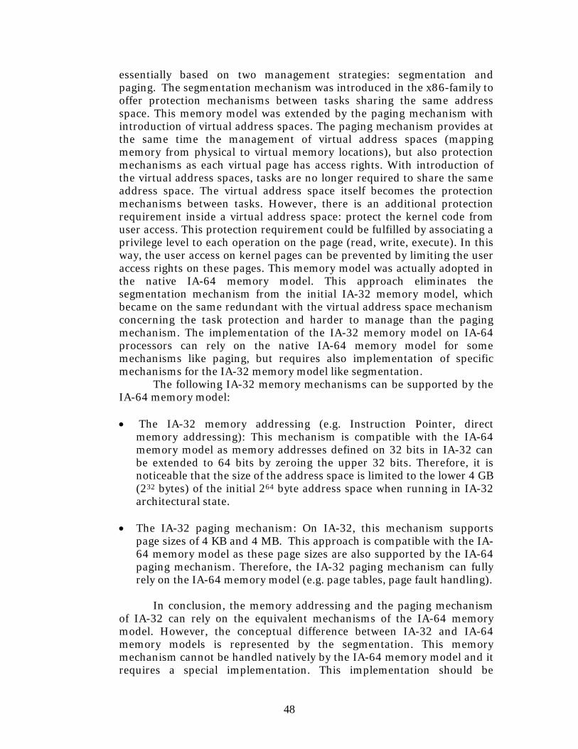
48
essentially based on two management strategies: segmentation and paging. The segmentation mechanism was introduced in the x86-family to offer protection mechanisms between tasks sharing the same address space. This memory model was extended by the paging mechanism with introduction of virtual address spaces. The paging mechanism provides at the same time the management of virtual address spaces (mapping memory from physical to virtual memory locations), but also protection mechanisms as each virtual page has access rights. With introduction of the virtual address spaces, tasks are no longer required to share the same address space. The virtual address space itself becomes the protection mechanisms between tasks. However, there is an additional protection requirement inside a virtual address space: protect the kernel code from user access. This protection requirement could be fulfilled by associating a privilege level to each operation on the page (read, write, execute). In this way, the user access on kernel pages can be prevented by limiting the user access rights on these pages. This memory model was actually adopted in the native IA-64 memory model. This approach eliminates the segmentation mechanism from the initial IA-32 memory model, which became on the same redundant with the virtual address space mechanism concerning the task protection and harder to manage than the paging mechanism. The implementation of the IA-32 memory model on IA-64 processors can rely on the native IA-64 memory model for some mechanisms like paging, but requires also implementation of specific mechanisms for the IA-32 memory model like segmentation.
The following IA-32 memory mechanisms can be supported by the IA-64 memory model:
• The IA-32 memory addressing (e.g. Instruction Pointer, direct
memory addressing): This mechanism is compatible with the IA-64 memory model as memory addresses defined on 32 bits in IA-32 can be extended to 64 bits by zeroing the upper 32 bits. Therefore, it is noticeable that the size of the address space is limited to the lower 4 GB (232 bytes) of the initial 264 byte address space when running in IA-32 architectural state.
• The IA-32 paging mechanism: On IA-32, this mechanism supports
page sizes of 4 KB and 4 MB. This approach is compatible with the IA-64 memory model as these page sizes are also supported by the IA-64 paging mechanism. Therefore, the IA-32 paging mechanism can fully rely on the IA-64 memory model (e.g. page tables, page fault handling).
In conclusion, the memory addressing and the paging mechanism
of IA-32 can rely on the equivalent mechanisms of the IA-64 memory model. However, the conceptual difference between IA-32 and IA-64 memory models is represented by the segmentation. This memory mechanism cannot be handled natively by the IA-64 memory model and it requires a special implementation. This implementation should be
49
IA-32 addresses
IA-64 addresses
Segmentation
(iVE)
Paging (MMU)
Zero Extension
(iVE)
Virtual Address Space (64 bit) Hardware
Address Space
64 bit page handling
Figure 4.4: Memory addressing in IA-32 and IA-64 modes
provided by the IA-32 emulation component (the iVE) as this hardware component receives the IA-32 instruction stream. The translation process of an IA-32 instruction to an IA-64 instruction should convert the memory addresses of arguments according to the segment layout (Figure 4.4). Any IA-32 segmentation fault can be acknowledged at this level and triggered as an exception. However, this segmentation mechanism assumes that the appropriate segment layout has been setup previously from switching the processor’s architectural state to IA-32. This task should be performed by the operating system. The segmentation mechanism induces an additional performance overhead in translating IA-32 instructions into native IA-64 instructions.
50
4.4 Horizontal design: IA-32 emulation layer on an IA-64 kernel
The best design approach for an Itanium based operating system is the “Native and Secondary Architectures” discussed in section 3.6. The IA-64 represents the native architectural state, while the IA-32 architecture can be considered as the secondary architecture.
This design approach provides an IA-64 kernel which natively performs IA-64 kernel services and an IA-32 emulation layer which provides emulated IA-32 kernel services. The IA-32 emulation layer simply establishes a communication channel between the IA-32 threads and the IA-64 kernel. Generally speaking, a communication process can be established if the two partners are “speaking the same language”. This is actually not the case with the IA-64 kernel and the IA-32 threads: the IA-64 kernel supports only the native IA-64 kernel interface, while the IA-32 threads access this interface according to the IA-32 specifications. This communication incompatibility is generated by the differences in data type representation between the two architectures: on IA-32, both the long and the pointer occupy 32 bits, while on the IA-64, these data types are represented on 64 bits. When the arguments required by the communication protocol involve these two data types, compatibility issues in communication may appear. As a consequence, the communication channel has to provide a mechanism to solve any communication issue generated by the incompatibility in data type representations. This mechanism acts like a translator enabling communication between “speakers with different languages”. This solution provides architecture transparency for IA-32 threads: an IA-32 thread cannot make the difference between running on an IA-32 operating system and running on an IA-64 operating system.
Besides the interface compatibility with IA-32 threads, the IA-64 kernel should also provide support for IA-32 faults and traps. This requirement is due to an implementation aspect of Itanium processors which states that all types of interrupts will be handled in the native IA-64 mode (see section 4.3.2). Even if a subset of IA-32 faults and traps are triggered as native IA-64 exceptions (e.g. page fault), most of the IA-32 exceptions require special handling.
The emulation of the IA-32 system interface and the IA-32 exception handling are the main issues of the IA-64 kernel support for the IA-32 architectural state. In addition, the kernel has to offer support for the IA-32 memory segmentation (by properly initializing the segment related tables and registers) and to handle context switches between the IA-32 and the IA-64 user-level binaries.
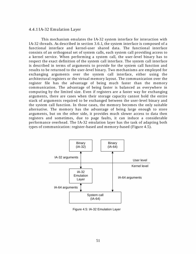
51
4.4.1 IA-32 Emulation Layer
This mechanism emulates the IA-32 system interface for interaction with IA-32 threads. As described in section 3.6.1, the system interface is composed of a functional interface and kernel-user shared data. The functional interface consists of an orthogonal set of system calls, each system call providing access to a kernel service. When performing a system call, the user-level binary has to respect the exact definition of the system call interface. The system call interface is described in terms of arguments to provide for the system call function and results to be returned to the user-level binary. Two mechanisms are employed for exchanging arguments over the system call interface, either using the architectural registers or the virtual memory layout. The communication over the register file has the advantage of being much faster than the memory communication. The advantage of being faster is balanced as everywhere in computing by the limited size. Even if registers are a faster way for exchanging arguments, there are cases when their storage capacity cannot hold the entire stack of arguments required to be exchanged between the user-level binary and the system call function. In those cases, the memory becomes the only suitable alternative. The memory has the advantage of being large enough to store arguments, but on the other side, it provides much slower access to data then registers and sometimes, due to page faults, it can induce a considerable performance overhead. The IA-32 emulation layer has the task of adapting both types of communication: register-based and memory-based (Figure 4.5).
IA-64 arguments
User level IA-32 arguments
Kernel level
System call (IA-64)
Binary (IA-32)
IA-32 Emulation
Layer
Figure 4.5: IA-32 Emulation Layer
Binary (IA-64)
IA-64 arguments
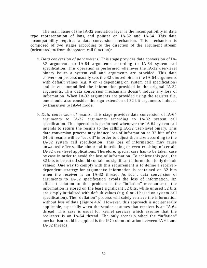
52
The main issue of the IA-32 emulation layer is the incompatibility in data
type representation of long and pointer on IA-32 and IA-64. This data incompatibility requires a data conversion mechanism. This mechanism is composed of two stages according to the direction of the argument stream (orientated to/from the system call function):
a. Data conversion of parameters: This stage provides data conversion of IA-
32 arguments to IA-64 arguments according to IA-64 system call specification. This operation is performed whenever the IA-32 user-level binary issues a system call and arguments are provided. This data conversion process usually sets the 32 unused bits in the IA-64 arguments with default values (e.g. 0 or -1 depending on system call specification) and leaves unmodified the information provided in the original IA-32 arguments. This data conversion mechanism doesn’t induce any loss of information. When IA-32 arguments are provided using the register file, one should also consider the sign extension of 32 bit arguments induced by transition to IA-64 mode.
b. Data conversion of results: This stage provides data conversion of IA-64
arguments to IA-32 arguments according to IA-32 system call specification. This operation is performed whenever the IA-64 system call intends to return the results to the calling IA-32 user-level binary. This data conversion process may induce loss of information as 32 bits of the 64 bit results will be “cut off” in order to adjust their size according to the IA-32 system call specification. This loss of information may cause unwanted effects, like abnormal functioning or even crashing of certain IA-32 user-level applications. Therefore, special care has to be taken case by case in order to avoid the loss of information. To achieve this goal, the 32 bits to be cut off should contain no significant information (only default values). One way to comply with this requirement is to define a receiver-dependent strategy for arguments: information is contained on 32 bits when the receiver is an IA-32 thread. As such, data conversion of arguments to IA-32 specification avoids the loss of information. An efficient solution to this problem is the “inflation” mechanism: the information is stored on the least significant 32 bits, while unused 32 bits are simply initialized with default values (e.g. 0 or -1 based on system call specification). The “deflation” process will safely retrieve the information without loss of data (Figure 4.6). However, this approach is not generally applicable, especially when the sender assumes that receiver is an IA-64 thread. This case is usual for kernel services which assume that the requester is an IA-64 thread. The only scenario when the “inflation” mechanism could be applied is the IPC communication between IA-64 and IA-32 threads.
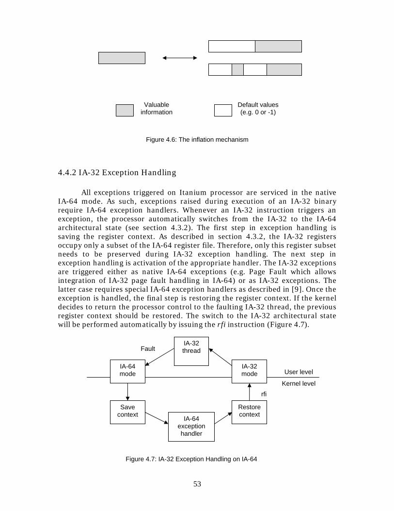
53
4.4.2 IA-32 Exception Handling
All exceptions triggered on Itanium processor are serviced in the native IA-64 mode. As such, exceptions raised during execution of an IA-32 binary require IA-64 exception handlers. Whenever an IA-32 instruction triggers an exception, the processor automatically switches from the IA-32 to the IA-64 architectural state (see section 4.3.2). The first step in exception handling is saving the register context. As described in section 4.3.2, the IA-32 registers occupy only a subset of the IA-64 register file. Therefore, only this register subset needs to be preserved during IA-32 exception handling. The next step in exception handling is activation of the appropriate handler. The IA-32 exceptions are triggered either as native IA-64 exceptions (e.g. Page Fault which allows integration of IA-32 page fault handling in IA-64) or as IA-32 exceptions. The latter case requires special IA-64 exception handlers as described in [9]. Once the exception is handled, the final step is restoring the register context. If the kernel decides to return the processor control to the faulting IA-32 thread, the previous register context should be restored. The switch to the IA-32 architectural state will be performed automatically by issuing the rfi instruction (Figure 4.7).
Valuable information
Figure 4.6: The inflation mechanism
Default values (e.g. 0 or -1)
Kernel level
User level
rfi
IA-32 thread
IA-64 exception handler
Figure 4.7: IA-32 Exception Handling on IA-64
Fault
IA-64 mode
Save context
IA-32 mode
Restore context
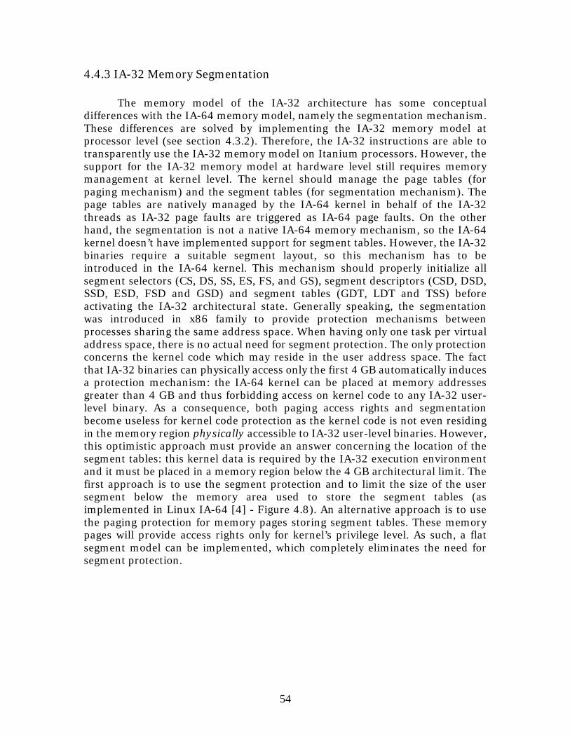
54
4.4.3 IA-32 Memory Segmentation
The memory model of the IA-32 architecture has some conceptual differences with the IA-64 memory model, namely the segmentation mechanism. These differences are solved by implementing the IA-32 memory model at processor level (see section 4.3.2). Therefore, the IA-32 instructions are able to transparently use the IA-32 memory model on Itanium processors. However, the support for the IA-32 memory model at hardware level still requires memory management at kernel level. The kernel should manage the page tables (for paging mechanism) and the segment tables (for segmentation mechanism). The page tables are natively managed by the IA-64 kernel in behalf of the IA-32 threads as IA-32 page faults are triggered as IA-64 page faults. On the other hand, the segmentation is not a native IA-64 memory mechanism, so the IA-64 kernel doesn’t have implemented support for segment tables. However, the IA-32 binaries require a suitable segment layout, so this mechanism has to be introduced in the IA-64 kernel. This mechanism should properly initialize all segment selectors (CS, DS, SS, ES, FS, and GS), segment descriptors (CSD, DSD, SSD, ESD, FSD and GSD) and segment tables (GDT, LDT and TSS) before activating the IA-32 architectural state. Generally speaking, the segmentation was introduced in x86 family to provide protection mechanisms between processes sharing the same address space. When having only one task per virtual address space, there is no actual need for segment protection. The only protection concerns the kernel code which may reside in the user address space. The fact that IA-32 binaries can physically access only the first 4 GB automatically induces a protection mechanism: the IA-64 kernel can be placed at memory addresses greater than 4 GB and thus forbidding access on kernel code to any IA-32 user-level binary. As a consequence, both paging access rights and segmentation become useless for kernel code protection as the kernel code is not even residing in the memory region physically accessible to IA-32 user-level binaries. However, this optimistic approach must provide an answer concerning the location of the segment tables: this kernel data is required by the IA-32 execution environment and it must be placed in a memory region below the 4 GB architectural limit. The first approach is to use the segment protection and to limit the size of the user segment below the memory area used to store the segment tables (as implemented in Linux IA-64 [4] - Figure 4.8). An alternative approach is to use the paging protection for memory pages storing segment tables. These memory pages will provide access rights only for kernel’s privilege level. As such, a flat segment model can be implemented, which completely eliminates the need for segment protection.
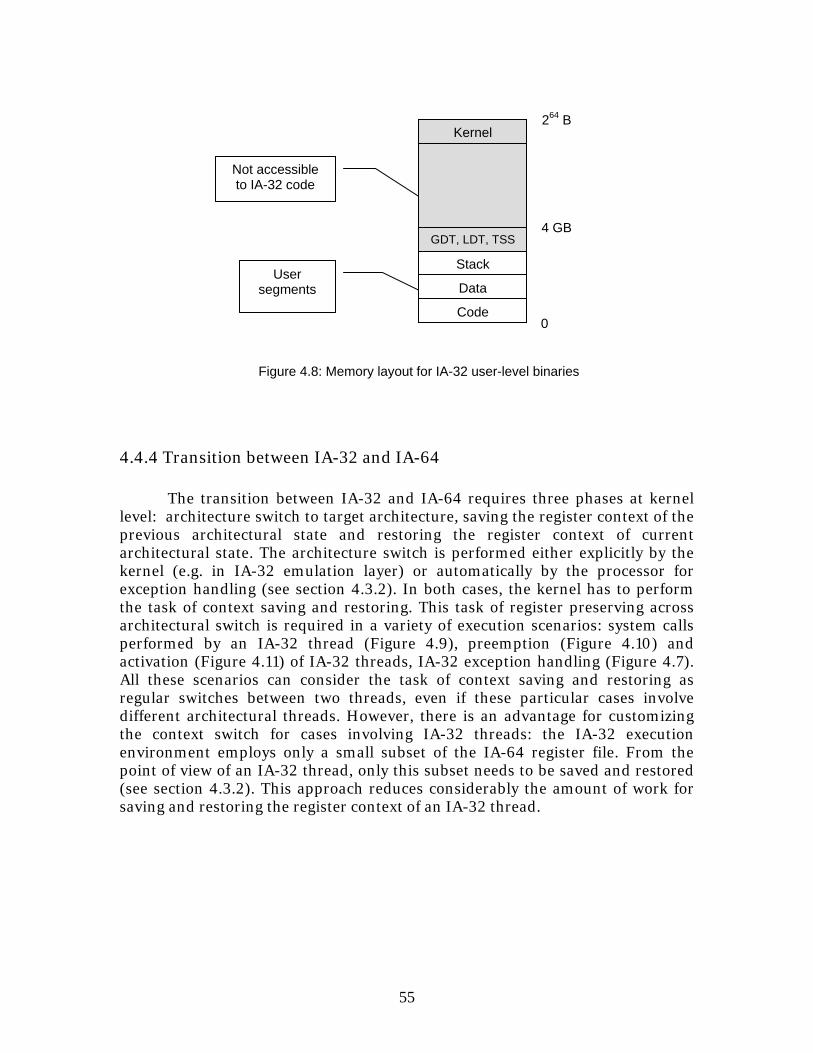
55
4.4.4 Transition between IA-32 and IA-64
The transition between IA-32 and IA-64 requires three phases at kernel level: architecture switch to target architecture, saving the register context of the previous architectural state and restoring the register context of current architectural state. The architecture switch is performed either explicitly by the kernel (e.g. in IA-32 emulation layer) or automatically by the processor for exception handling (see section 4.3.2). In both cases, the kernel has to perform the task of context saving and restoring. This task of register preserving across architectural switch is required in a variety of execution scenarios: system calls performed by an IA-32 thread (Figure 4.9), preemption (Figure 4.10) and activation (Figure 4.11) of IA-32 threads, IA-32 exception handling (Figure 4.7). All these scenarios can consider the task of context saving and restoring as regular switches between two threads, even if these particular cases involve different architectural threads. However, there is an advantage for customizing the context switch for cases involving IA-32 threads: the IA-32 execution environment employs only a small subset of the IA-64 register file. From the point of view of an IA-32 thread, only this subset needs to be saved and restored (see section 4.3.2). This approach reduces considerably the amount of work for saving and restoring the register context of an IA-32 thread.
264 B
User segments
Not accessible to IA-32 code
4 GB
0
Data
Code
Figure 4.8: Memory layout for IA-32 user-level binaries
Stack
Kernel
GDT, LDT, TSS
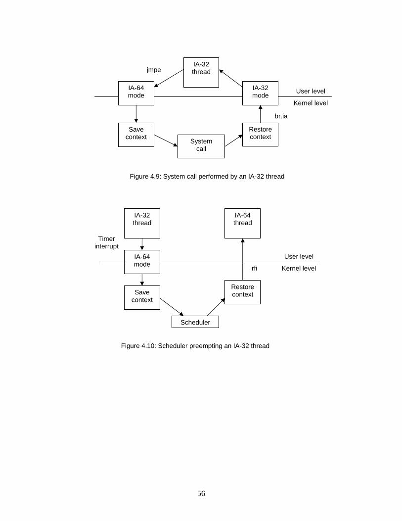
56
Kernel level
User level
Figure 4.9: System call performed by an IA-32 thread
br.ia
IA-32 thread
System call
jmpe
IA-64 mode
Save context
IA-32 mode
Restore context
rfi Kernel level
User level
Figure 4.10: Scheduler preempting an IA-32 thread
Timer interrupt
IA-64 thread
Scheduler
IA-64 mode
Save context
Restore context
IA-32 thread
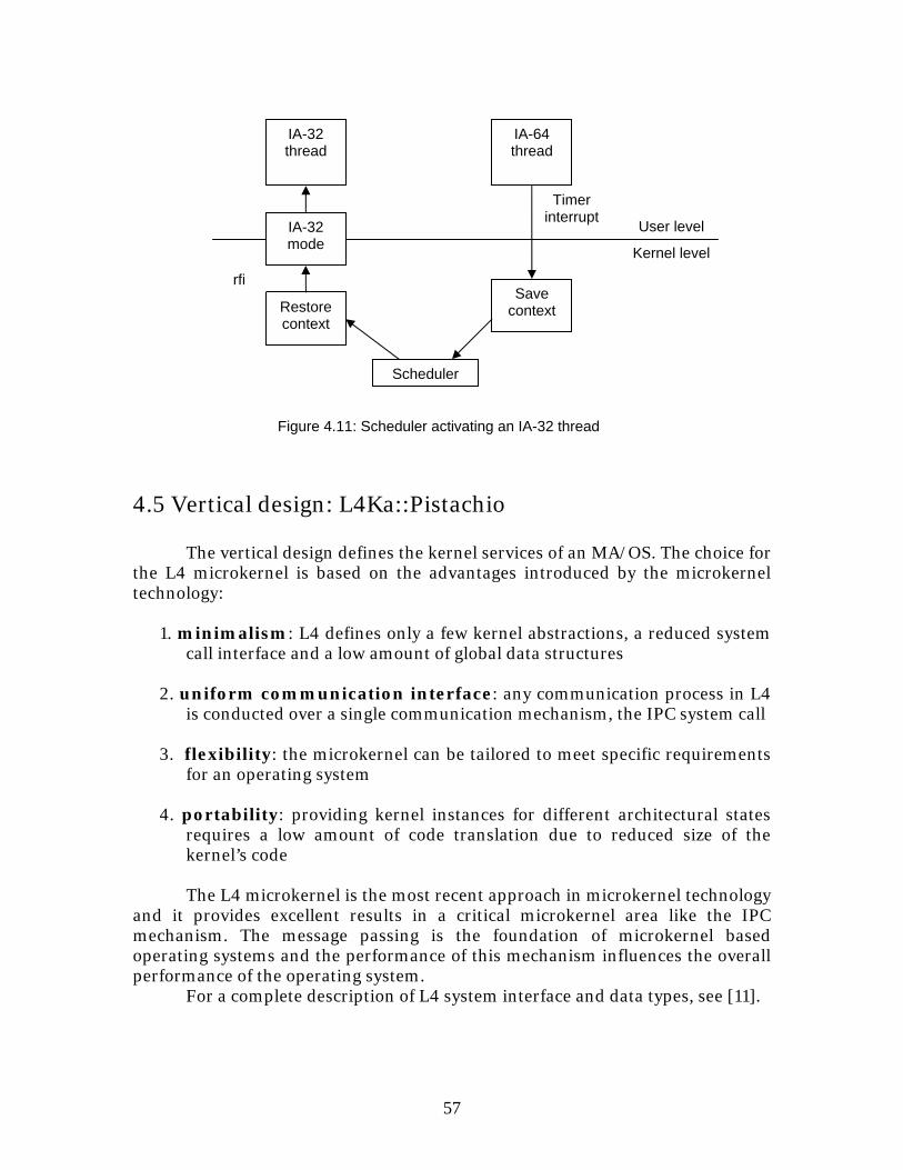
57
4.5 Vertical design: L4Ka::Pistachio The vertical design defines the kernel services of an MA/OS. The choice for the L4 microkernel is based on the advantages introduced by the microkernel technology:
1. minimalism: L4 defines only a few kernel abstractions, a reduced system call interface and a low amount of global data structures
2. uniform communication interface: any communication process in L4
is conducted over a single communication mechanism, the IPC system call 3. flexibility: the microkernel can be tailored to meet specific requirements
for an operating system 4. portability: providing kernel instances for different architectural states
requires a low amount of code translation due to reduced size of the kernel’s code
The L4 microkernel is the most recent approach in microkernel technology and it provides excellent results in a critical microkernel area like the IPC mechanism. The message passing is the foundation of microkernel based operating systems and the performance of this mechanism influences the overall performance of the operating system. For a complete description of L4 system interface and data types, see [11].
Timer interrupt
Kernel level
User level
Figure 4.11: Scheduler activating an IA-32 thread
IA-64 thread
Scheduler
IA-32 mode
Restore context
Save context
IA-32 thread
rfi
58
4.6 Co-design process of the MA/OS
The design process of a MA/OS requires two orthogonal sub-designs: the horizontal design which provides a solution to the architectural heterogeneity of the computing system and the vertical design which provides the kernel services independent of any architectural state.
The best suitable horizontal design for an Itanium based system is the “Native and Secondary architectures” (see section 3.6). The main issues of this design model were discussed previously in this chapter (see section 4.4). These issues generally apply to any MA/OS build on top of an Itanium based system.
The choice of this experimental approach for a vertical design is the L4 microkernel (see section 4.5). The microkernel technology looks very promising for designing MA/OSs, mostly due to minimalism in kernel abstractions and global data structures.
Given the horizontal and the vertical designs, the main question is the way to couple these two sub-designs. In this case study, the base of the global design is the L4 microkernel, as it provides the kernel services. The horizontal design (the IA-32 emulation layer) is only a solution on how to adapt a kernel structure to comply with the architectural heterogeneity of the computing system.
The global design has some specific requirements which influence the construction of the operating system:
1. Provide operating system transparency for the IA-32 user-level binaries
The IA-32 user-level binaries are enabled to run on an IA-64 operating system on “as is” basis, without any adjustments required. The IA-64 kernel has to adapt its system interface to support the IA-32 system interface.
2. Reduce as possible the performance overhead for IA-64 user-level
binaries The integration of the IA-32 support in the IA-64 kernel may induce a
performance overhead for native IA-64 binaries. This side effect should be prevented or minimized as possible. User-level binaries are more likely to use the IA-64 rather then the IA-32 (for computing performance), so the performance overhead for IA-64 user-level binaries should be reduced as possible.
These two requirements have an important influence on the kernel design
and implementation. One direct consequence is the modularity in implementing the support for IA-32 user-level binaries: a separation of the IA-32 support from the native IA-64 kernel is less likely to induce a performance overhead for IA-64 user-level binaries. This approach complies with the second requirement of this design.
The global design must integrate the mechanisms of the horizontal design into the vertical design while respecting the global design requirements.
59
4.6.1 IA-32 emulation layer in Pistachio IA-64
Pistachio IA-64 should integrate the IA-32 system interface defined according to the L4 specifications. The IA-32 system interface defined in L4 microkernel consists of a functional interface (the set of system call interfaces) and shared user-kernel data structures (the KIP and the UTCB).
Each system call interface is described in terms of arguments to provide for the system call functions and results to be returned to the calling thread. These arguments can be provided either through the register file or through shared user-kernel data (the UTCB). The register file provides a much faster way to exchange arguments than memory and therefore, they have a higher usage in the user-kernel communication process. In the case of L4, this method of passing arguments is employed by all system call functions. However, in spite of the performance advantage of register communication, there are cases when the memory storage cannot be avoided, especially when the arguments cannot fit in the register file. As a point in case, the message to be transmitted through an IPC system call may be too large to fit in the register file. In this case, the arguments that cannot fit in registers are written in memory in a reserved memory area, both user and kernel accessible: the UTCB. Another reason for using the memory storage for exchanging arguments is fast access on user-configuration data (the TCR) and on kernel-configuration data (the KIP). Direct access on these data structures prevents the overhead of a system call for retrieving this information.
In short, the L4 system call interface is defined using the register file and user-kernel shared data (UTCB and KIP). Both methods of transferring arguments are architecture specific: the structure of the register file depends on the CPU architecture, while the UTCB and the KIP contain data types which have architecture specific representations. As a consequence, the IA-32 system interface has a different implementation from the IA-64 system interface. The IA-32 system interface will be integrated in the IA-32 emulation layer.
The first element of the L4 system interface is the functional interface, composed of a set of system calls. The implementation of a system call is structurally divided in two stages: the system call stub and the system call function. The system call function is the stage practically performing the kernel service, while the system call stub is only the system call interface which handles the interaction with the outside world (the user-level binaries). The system call stub handles all issues related to arguments: availability, correctness according to specification, data conversion. This structural separation of the system call implementation enables the support for different system call interfaces: a system call stub will be provided according to the target specification, while the system call function itself remains unmodified. This approach reduces considerably the task of an emulation layer. The IA-32 emulation layer has only to provide the IA-32 system call stubs in order to achieve IA-32 system call compatibility (Figure 4.12).
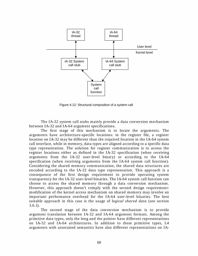
60
The IA-32 system call stubs mainly provide a data conversion mechanism
between IA-32 and IA-64 argument specifications. The first stage of this mechanism is to locate the arguments. The
arguments have architecture-specific locations: in the register file, a register location on IA-32 may be different than the required location in the IA-64 system call interface, while in memory, data types are aligned according to a specific data type representation. The solution for register communication is to access the register locations either as defined in the IA-32 specification (when receiving arguments from the IA-32 user-level binary) or according to the IA-64 specification (when receiving arguments from the IA-64 system call function). Considering the shared memory communication, the shared data structures are encoded according to the IA-32 data type representation. This approach is a consequence of the first design requirement to provide operating system transparency for the IA-32 user-level binaries. The IA-64 system call function can choose to access the shared memory through a data conversion mechanism. However, this approach doesn’t comply with the second design requirement: modification of the kernel access mechanism on shared memory may involve an important performance overhead for the IA-64 user-level binaries. The best suitable approach in this case is the usage of logical shared data (see section 3.6.1). The second stage of the data conversion mechanism is to provide argument translation between IA-32 and IA-64 argument formats. Among the primitive data types, only the long and the pointer have different representations on IA-32 and IA-64 architectures. In addition to these primitive types, L4 arguments with associated semantics have also different representations on IA-
Kernel level
IA-32 thread
IA-32 System call stub
System call
function
User level
IA-64 System call stub
IA-64 thread
Figure 4.12: Structural composition of a system call
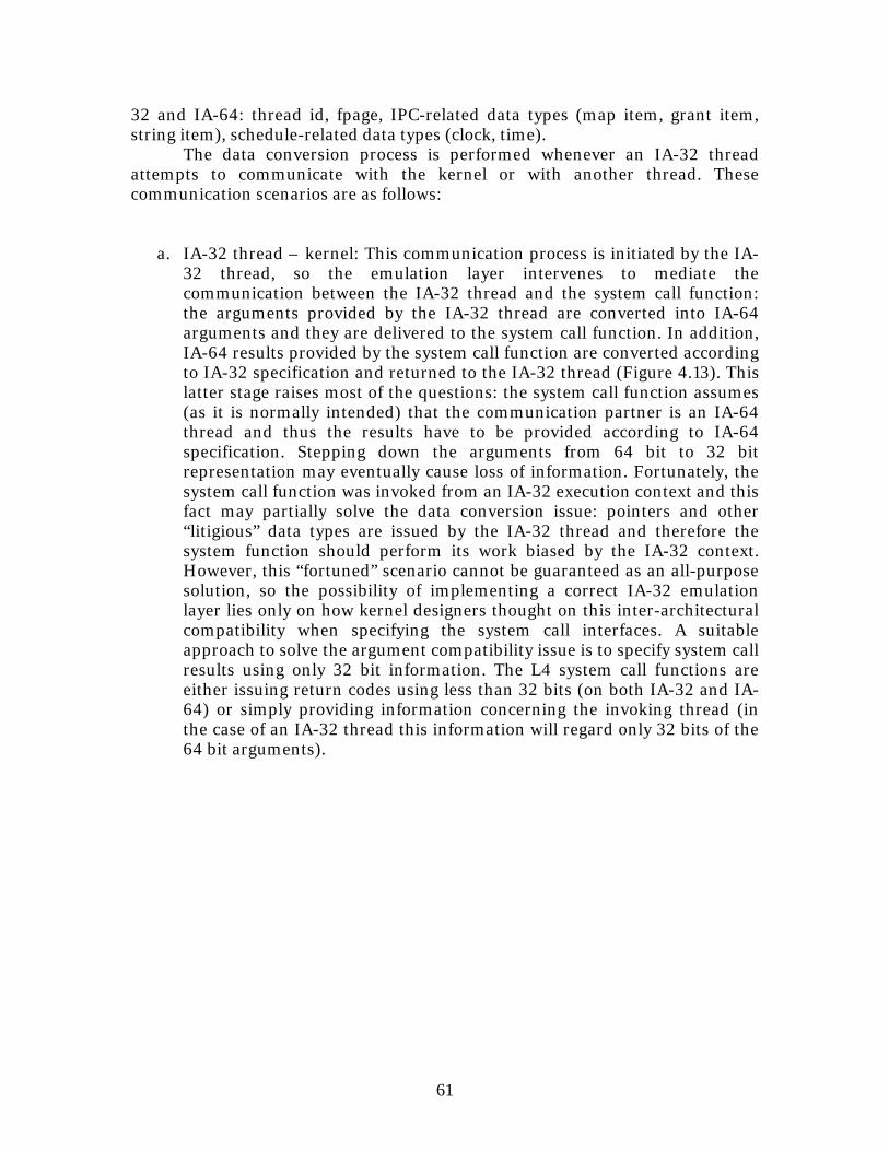
61
32 and IA-64: thread id, fpage, IPC-related data types (map item, grant item, string item), schedule-related data types (clock, time).
The data conversion process is performed whenever an IA-32 thread attempts to communicate with the kernel or with another thread. These communication scenarios are as follows:
a. IA-32 thread – kernel: This communication process is initiated by the IA-
32 thread, so the emulation layer intervenes to mediate the communication between the IA-32 thread and the system call function: the arguments provided by the IA-32 thread are converted into IA-64 arguments and they are delivered to the system call function. In addition, IA-64 results provided by the system call function are converted according to IA-32 specification and returned to the IA-32 thread (Figure 4.13). This latter stage raises most of the questions: the system call function assumes (as it is normally intended) that the communication partner is an IA-64 thread and thus the results have to be provided according to IA-64 specification. Stepping down the arguments from 64 bit to 32 bit representation may eventually cause loss of information. Fortunately, the system call function was invoked from an IA-32 execution context and this fact may partially solve the data conversion issue: pointers and other “litigious” data types are issued by the IA-32 thread and therefore the system function should perform its work biased by the IA-32 context. However, this “fortuned” scenario cannot be guaranteed as an all-purpose solution, so the possibility of implementing a correct IA-32 emulation layer lies only on how kernel designers thought on this inter-architectural compatibility when specifying the system call interfaces. A suitable approach to solve the argument compatibility issue is to specify system call results using only 32 bit information. The L4 system call functions are either issuing return codes using less than 32 bits (on both IA-32 and IA-64) or simply providing information concerning the invoking thread (in the case of an IA-32 thread this information will regard only 32 bits of the 64 bit arguments).
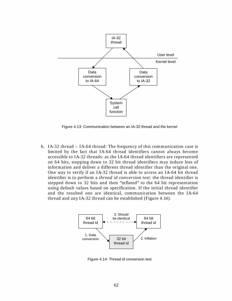
62
b. IA-32 thread – IA-64 thread: The frequency of this communication case is
limited by the fact that IA-64 thread identifiers cannot always become accessible to IA-32 threads: as the IA-64 thread identifiers are represented on 64 bits, stepping down to 32 bit thread identifiers may induce loss of information and deliver a different thread identifier than the original one. One way to verify if an IA-32 thread is able to access an IA-64 bit thread identifier is to perform a thread id conversion test: the thread identifier is stepped down to 32 bits and then “inflated” to the 64 bit representation using default values based on specification. If the initial thread identifier and the resulted one are identical, communication between the IA-64 thread and any IA-32 thread can be established (Figure 4.14).
2. Inflation 1. Data
conversion
64 bit thread id
32 bit thread id
64 bit thread id
3. Should be identical
Figure 4.14: Thread id conversion test
Kernel level
IA-32 thread
Data conversion
to IA-64
Data conversion
to IA-32
System call
function
User level
Figure 4.13: Communication between an IA-32 thread and the kernel
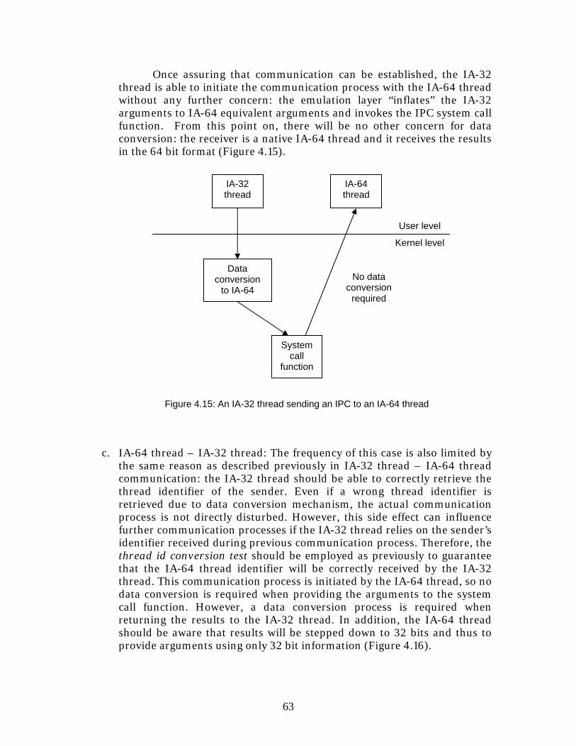
63
Once assuring that communication can be established, the IA-32 thread is able to initiate the communication process with the IA-64 thread without any further concern: the emulation layer “inflates” the IA-32 arguments to IA-64 equivalent arguments and invokes the IPC system call function. From this point on, there will be no other concern for data conversion: the receiver is a native IA-64 thread and it receives the results in the 64 bit format (Figure 4.15).
c. IA-64 thread – IA-32 thread: The frequency of this case is also limited by the same reason as described previously in IA-32 thread – IA-64 thread communication: the IA-32 thread should be able to correctly retrieve the thread identifier of the sender. Even if a wrong thread identifier is retrieved due to data conversion mechanism, the actual communication process is not directly disturbed. However, this side effect can influence further communication processes if the IA-32 thread relies on the sender’s identifier received during previous communication process. Therefore, the thread id conversion test should be employed as previously to guarantee that the IA-64 thread identifier will be correctly received by the IA-32 thread. This communication process is initiated by the IA-64 thread, so no data conversion is required when providing the arguments to the system call function. However, a data conversion process is required when returning the results to the IA-32 thread. In addition, the IA-64 thread should be aware that results will be stepped down to 32 bits and thus to provide arguments using only 32 bit information (Figure 4.16).
Kernel level
IA-32 thread
Data conversion
to IA-64
System call
function
User level
IA-64 thread
No data conversion
required
Figure 4.15: An IA-32 thread sending an IPC to an IA-64 thread
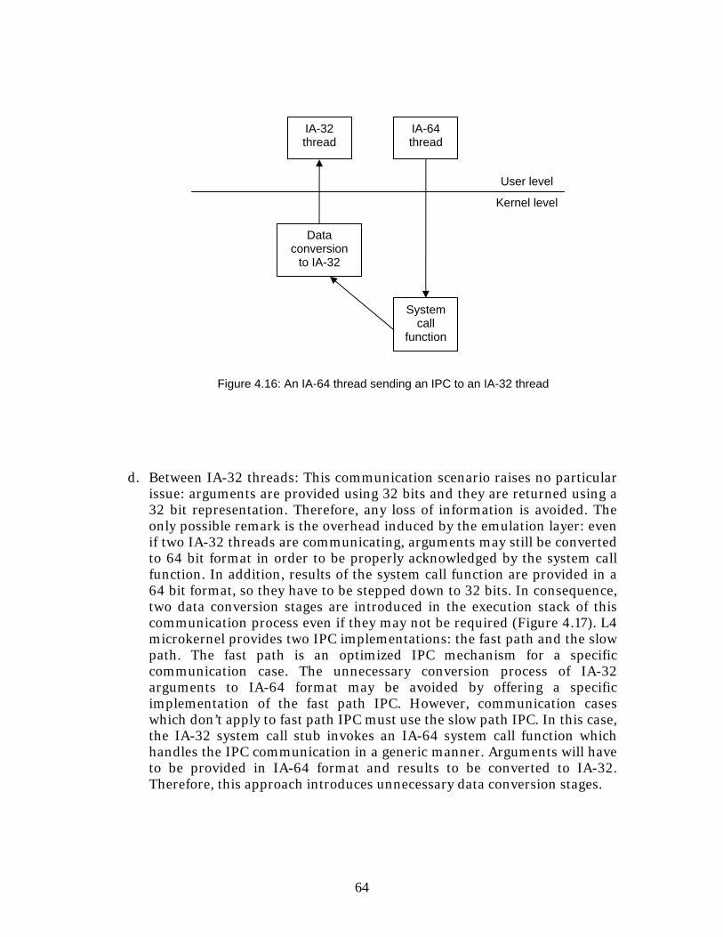
64
d. Between IA-32 threads: This communication scenario raises no particular issue: arguments are provided using 32 bits and they are returned using a 32 bit representation. Therefore, any loss of information is avoided. The only possible remark is the overhead induced by the emulation layer: even if two IA-32 threads are communicating, arguments may still be converted to 64 bit format in order to be properly acknowledged by the system call function. In addition, results of the system call function are provided in a 64 bit format, so they have to be stepped down to 32 bits. In consequence, two data conversion stages are introduced in the execution stack of this communication process even if they may not be required (Figure 4.17). L4 microkernel provides two IPC implementations: the fast path and the slow path. The fast path is an optimized IPC mechanism for a specific communication case. The unnecessary conversion process of IA-32 arguments to IA-64 format may be avoided by offering a specific implementation of the fast path IPC. However, communication cases which don’t apply to fast path IPC must use the slow path IPC. In this case, the IA-32 system call stub invokes an IA-64 system call function which handles the IPC communication in a generic manner. Arguments will have to be provided in IA-64 format and results to be converted to IA-32. Therefore, this approach introduces unnecessary data conversion stages.
Kernel level
IA-32 thread
Data conversion
to IA-32
System call
function
User level
IA-64 thread
Figure 4.16: An IA-64 thread sending an IPC to an IA-32 thread
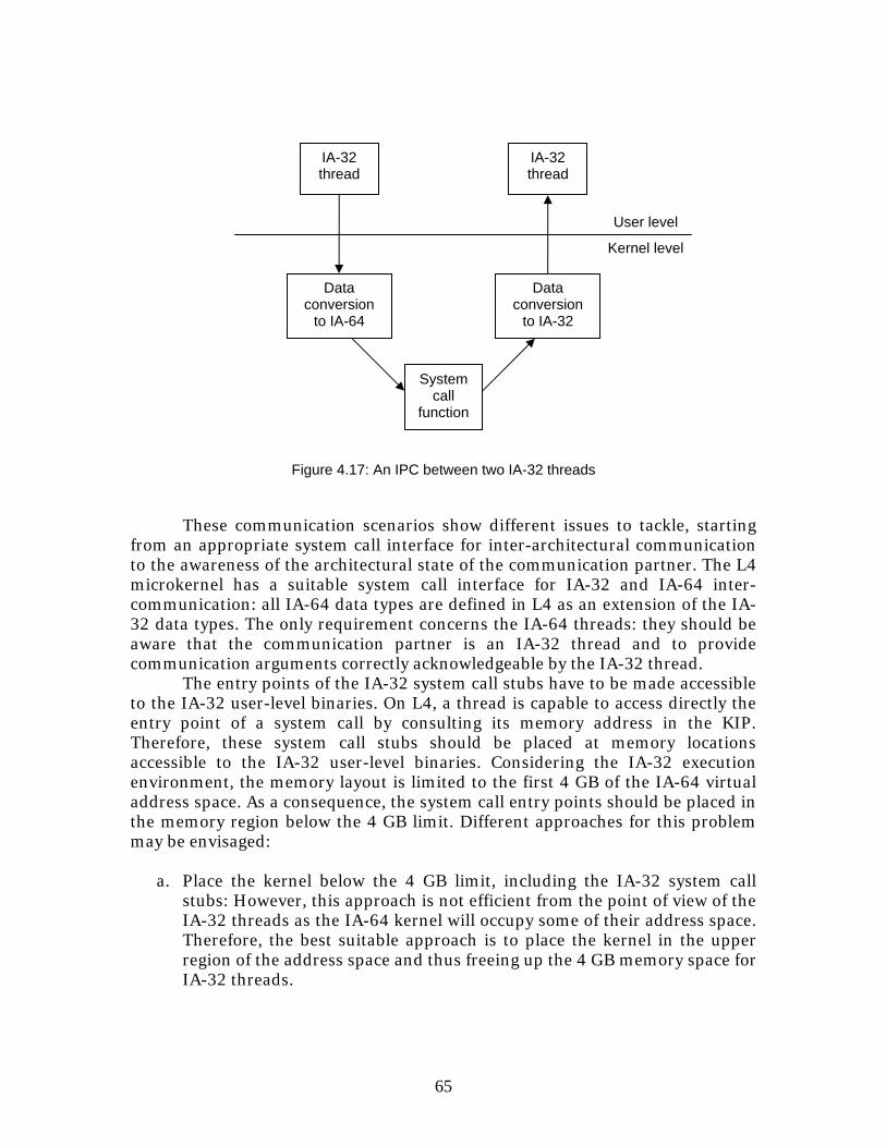
65
These communication scenarios show different issues to tackle, starting from an appropriate system call interface for inter-architectural communication to the awareness of the architectural state of the communication partner. The L4 microkernel has a suitable system call interface for IA-32 and IA-64 inter-communication: all IA-64 data types are defined in L4 as an extension of the IA-32 data types. The only requirement concerns the IA-64 threads: they should be aware that the communication partner is an IA-32 thread and to provide communication arguments correctly acknowledgeable by the IA-32 thread.
The entry points of the IA-32 system call stubs have to be made accessible to the IA-32 user-level binaries. On L4, a thread is capable to access directly the entry point of a system call by consulting its memory address in the KIP. Therefore, these system call stubs should be placed at memory locations accessible to the IA-32 user-level binaries. Considering the IA-32 execution environment, the memory layout is limited to the first 4 GB of the IA-64 virtual address space. As a consequence, the system call entry points should be placed in the memory region below the 4 GB limit. Different approaches for this problem may be envisaged:
a. Place the kernel below the 4 GB limit, including the IA-32 system call
stubs: However, this approach is not efficient from the point of view of the IA-32 threads as the IA-64 kernel will occupy some of their address space. Therefore, the best suitable approach is to place the kernel in the upper region of the address space and thus freeing up the 4 GB memory space for IA-32 threads.
Kernel level
IA-32 thread
Data conversion
to IA-64
System call
function
User level
IA-32 thread
Figure 4.17: An IPC between two IA-32 threads
Data conversion
to IA-32
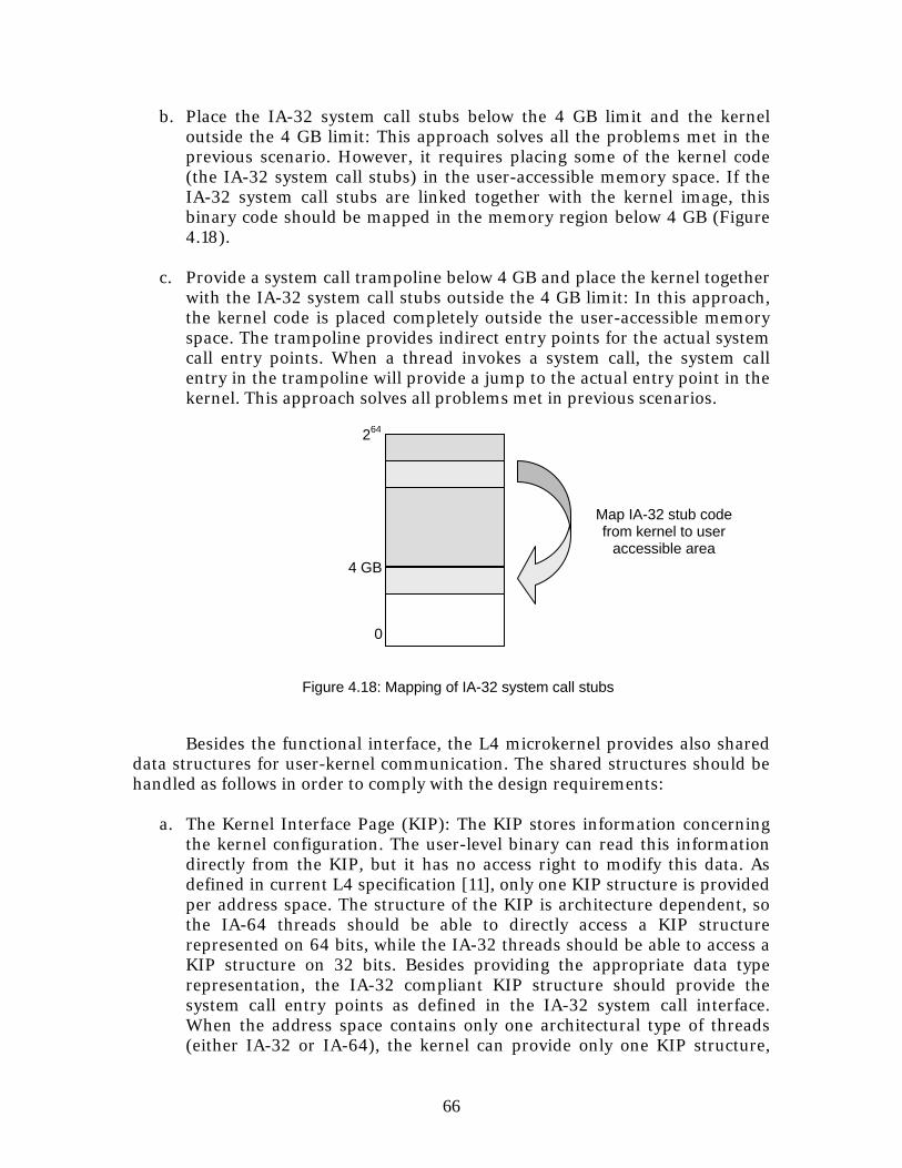
66
b. Place the IA-32 system call stubs below the 4 GB limit and the kernel outside the 4 GB limit: This approach solves all the problems met in the previous scenario. However, it requires placing some of the kernel code (the IA-32 system call stubs) in the user-accessible memory space. If the IA-32 system call stubs are linked together with the kernel image, this binary code should be mapped in the memory region below 4 GB (Figure 4.18).
c. Provide a system call trampoline below 4 GB and place the kernel together
with the IA-32 system call stubs outside the 4 GB limit: In this approach, the kernel code is placed completely outside the user-accessible memory space. The trampoline provides indirect entry points for the actual system call entry points. When a thread invokes a system call, the system call entry in the trampoline will provide a jump to the actual entry point in the kernel. This approach solves all problems met in previous scenarios.
Besides the functional interface, the L4 microkernel provides also shared data structures for user-kernel communication. The shared structures should be handled as follows in order to comply with the design requirements:
a. The Kernel Interface Page (KIP): The KIP stores information concerning the kernel configuration. The user-level binary can read this information directly from the KIP, but it has no access right to modify this data. As defined in current L4 specification [11], only one KIP structure is provided per address space. The structure of the KIP is architecture dependent, so the IA-64 threads should be able to directly access a KIP structure represented on 64 bits, while the IA-32 threads should be able to access a KIP structure on 32 bits. Besides providing the appropriate data type representation, the IA-32 compliant KIP structure should provide the system call entry points as defined in the IA-32 system call interface. When the address space contains only one architectural type of threads (either IA-32 or IA-64), the kernel can provide only one KIP structure,
0
4 GB
264
Figure 4.18: Mapping of IA-32 system call stubs
Map IA-32 stub code from kernel to user
accessible area
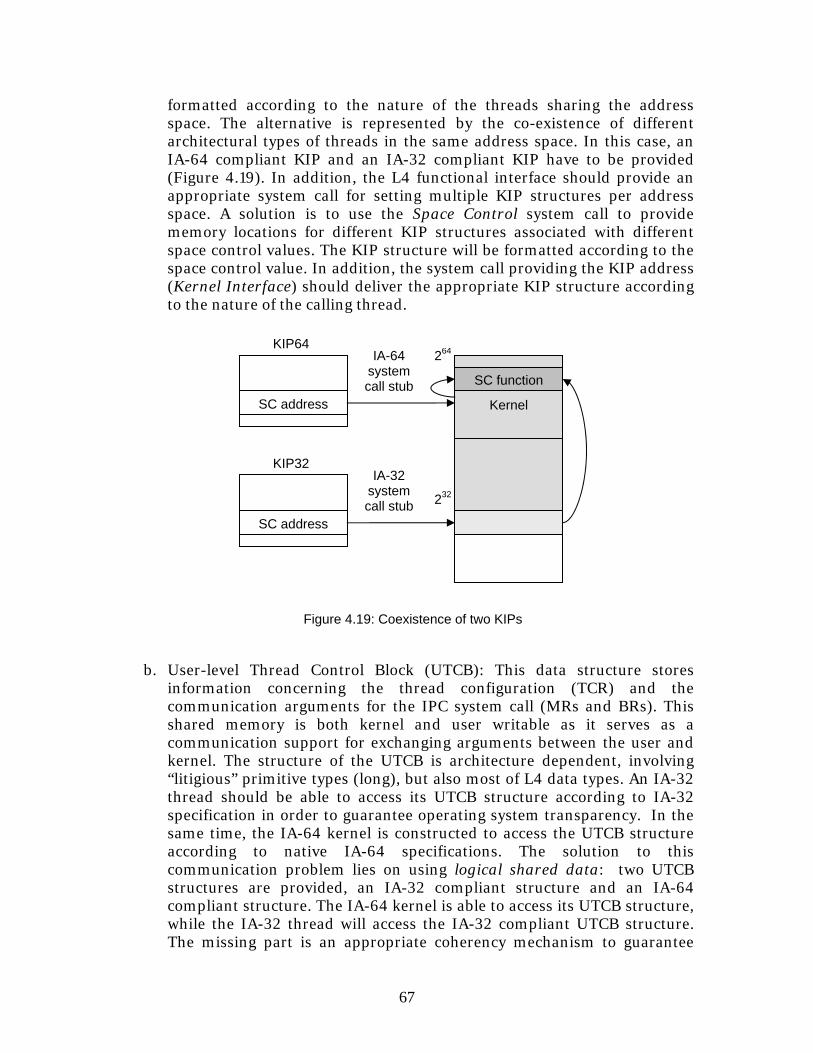
67
formatted according to the nature of the threads sharing the address space. The alternative is represented by the co-existence of different architectural types of threads in the same address space. In this case, an IA-64 compliant KIP and an IA-32 compliant KIP have to be provided (Figure 4.19). In addition, the L4 functional interface should provide an appropriate system call for setting multiple KIP structures per address space. A solution is to use the Space Control system call to provide memory locations for different KIP structures associated with different space control values. The KIP structure will be formatted according to the space control value. In addition, the system call providing the KIP address (Kernel Interface) should deliver the appropriate KIP structure according to the nature of the calling thread.
b. User-level Thread Control Block (UTCB): This data structure stores information concerning the thread configuration (TCR) and the communication arguments for the IPC system call (MRs and BRs). This shared memory is both kernel and user writable as it serves as a communication support for exchanging arguments between the user and kernel. The structure of the UTCB is architecture dependent, involving “litigious” primitive types (long), but also most of L4 data types. An IA-32 thread should be able to access its UTCB structure according to IA-32 specification in order to guarantee operating system transparency. In the same time, the IA-64 kernel is constructed to access the UTCB structure according to native IA-64 specifications. The solution to this communication problem lies on using logical shared data: two UTCB structures are provided, an IA-32 compliant structure and an IA-64 compliant structure. The IA-64 kernel is able to access its UTCB structure, while the IA-32 thread will access the IA-32 compliant UTCB structure. The missing part is an appropriate coherency mechanism to guarantee
KIP32 IA-32
system call stub
264
Kernel
SC function
232
Figure 4.19: Coexistence of two KIPs
SC address
KIP64 IA-64
system call stub
SC address
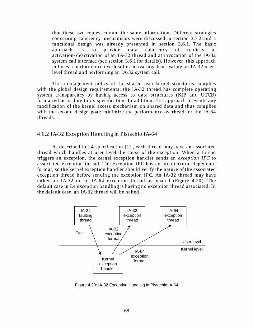
68
that these two copies contain the same information. Different strategies concerning coherency mechanisms were discussed in section 3.7.2 and a functional design was already presented in section 3.6.1. The basic approach is to provide data coherency of replicas at activation/deactivation of an IA-32 thread and at invocation of the IA-32 system call interface (see section 3.6.1 for details). However, this approach induces a performance overhead in activating/deactivating an IA-32 user-level thread and performing an IA-32 system call.
This management policy of the shared user-kernel structures complies
with the global design requirements: the IA-32 thread has complete operating system transparency by having access to data structures (KIP and UTCB) formatted according to its specification. In addition, this approach prevents any modification of the kernel access mechanism on shared data and thus complies with the second design goal: minimize the performance overhead for the IA-64 threads.
4.6.2 IA-32 Exception Handling in Pistachio IA-64 As described in L4 specification [11], each thread may have an associated thread which handles at user level the cause of the exception. When a thread triggers an exception, the kernel exception handler sends an exception IPC to associated exception thread. The exception IPC has an architectural dependant format, so the kernel exception handler should verify the nature of the associated exception thread before sending the exception IPC. An IA-32 thread may have either an IA-32 or an IA-64 exception thread associated (Figure 4.20). The default case in L4 exception handling is having no exception thread associated. In the default case, an IA-32 thread will be halted.
IA-64 exception
format
IA-32 exception
format
Kernel level
User level
IA-32 faulting thread
Kernel exception handler
Figure 4.20: IA-32 Exception Handling in Pistachio IA-64
Fault
IA-32 exception
thread
IA-64 exception
thread
69
4.6.3 IA-32 Memory Segmentation in Pistachio IA-64 The kernel must setup the segment tables for the IA-32 threads. This process is required whenever an IA-32 thread becomes active. Therefore, the task for setting up the segment registers should be integrated in the scheduler. In order not to alter the scheduling performance of IA-64 threads, this task should be implemented in specific IA-32 functions related to resource loading/saving. If the kernel resides outside the 4 GB limit of the IA-32 address space, the segment layout can be initialized using the flat segment model.
4.6.4 Transition between IA-32 and IA-64 in Pistachio IA-64 Different scenarios require transition between these two architectural states. In all cases, the main requirement is to preserve the register context of a thread across architecture switch. The IA-32 threads employ only general purpose registers (see the IA-32 register mapping on IA-64 register file [9]), while IA-64 threads employ register frames [9] requiring no saving/restoring of registers during direct invocation of a system call. So, the preservation of the register context is only related to the general purpose registers employed by the IA-32 threads. These registers can be modified by the kernel or other thread activity, so they should be saved and restored according to the IA-32 thread. Another requirement is to assure that the IA-32 segment layout and other IA-32 architectural registers (EFLAG, FSR, FCR, FIR, and FDR [9]) are in place before activating the IA-32 thread. Of course, the IA-64 threads are not concerned by this operation. This design process is an example of co-designing of an MA/OS starting from a horizontal design (Native and Secondary Architectures) and a vertical design (L4 microkernel). This design leads to an implementation based on the L4Ka::Pistachio. The evaluation of this experimental approach will be presented in the following chapter.
70
Chapter 5
Evaluation of the implementation This chapter evaluates the suitability of the MA/OS design based on the Itanium processor and the L4Ka::Pistachio. We first study the fulfillment of the design requirements. Once guaranteeing the respect of design requirements, a performance analysis of the implementation is undertaken to study the suitability of the theoretical solution.
5.1 Evaluation of design requirements
The main goal of the implementation was to verify that the design issues were properly tackled and the design requirements were fulfilled. These design requirements were presented in the section 4.6:
1. The first design requirement was to provide operating system transparency for the IA-32 user-level binaries. The current implementation based on L4Ka::Pistachio provides a complete system interface for the IA-32 user-level binaries:
a. IA-32 system call interface: an IA-32 user-level binary is able to issue any system call according to the IA-32 specification of the L4 Version X.2 API [11]
b. IA-32 compliant Kernel Interface Page (KIP): The kernel creates a KIP object formatted according to the IA-32 specification in each address space containing IA-32 threads.
c. IA-32 compliant User-level Thread Control Block (UTCB): Each IA-32 thread has a UTCB structure formatted according to the IA-32 specification.
In short, an IA-32 thread is able to interact with the IA-64 kernel exactly in the same way as interacting with the native IA-32 kernel. The first design requirement concerning operating system transparency for IA-32 user-level binaries is thus fulfilled.
2. The second design requirement was to reduce as much as possible the performance overhead for IA-64 user-level binaries. In contrast with the first requirement, which is a functional criterion, this second requirement is purely performance driven. The achievement of this design requirement can be analyzed only through a benchmarking approach concerning the performance of IA-64 threads. The main performance criterion in a microkernel design is the IPC performance [13]. The IPC performance was measured using two benchmarks: the first benchmark
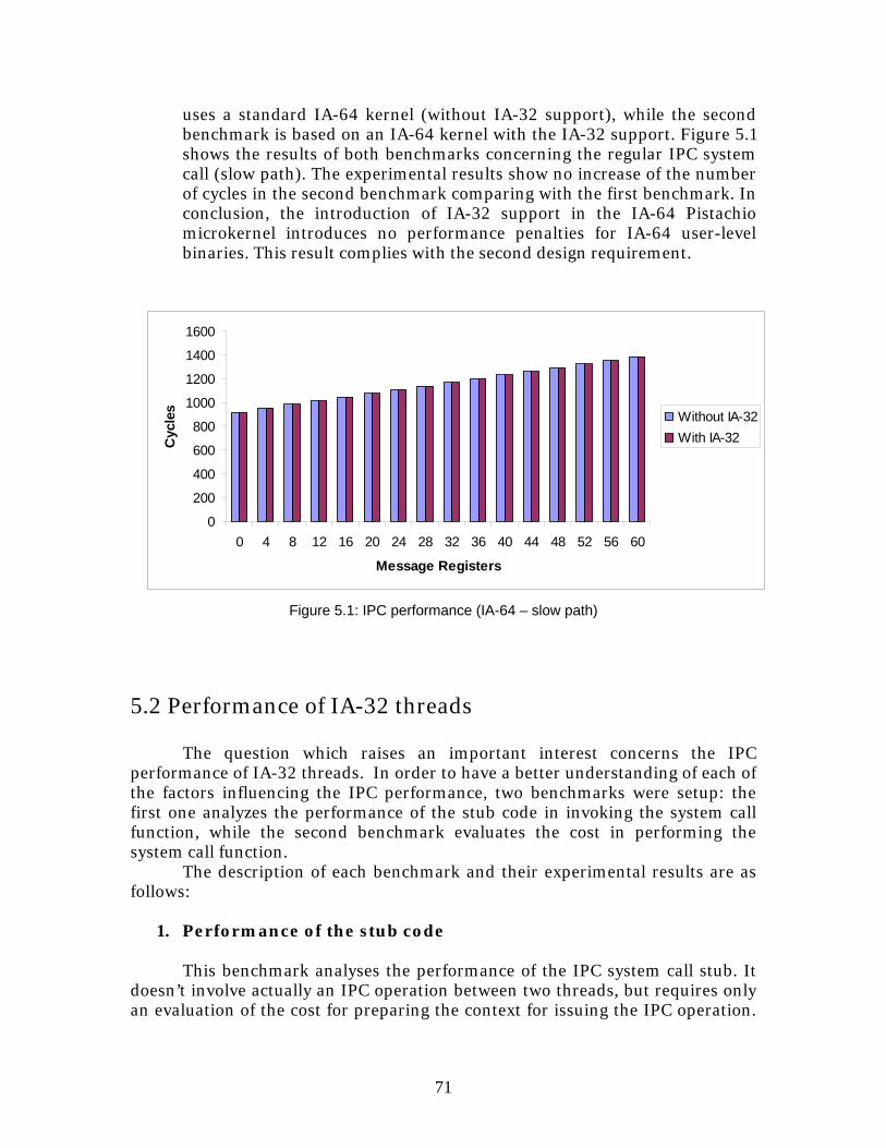
71
0
200
400
600
800
1000
1200
1400
1600
0 4 8 12 16 20 24 28 32 36 40 44 48 52 56 60
Message Registers
Cyc
les Without IA-32
With IA-32
uses a standard IA-64 kernel (without IA-32 support), while the second benchmark is based on an IA-64 kernel with the IA-32 support. Figure 5.1 shows the results of both benchmarks concerning the regular IPC system call (slow path). The experimental results show no increase of the number of cycles in the second benchmark comparing with the first benchmark. In conclusion, the introduction of IA-32 support in the IA-64 Pistachio microkernel introduces no performance penalties for IA-64 user-level binaries. This result complies with the second design requirement.
Figure 5.1: IPC performance (IA-64 – slow path)
5.2 Performance of IA-32 threads
The question which raises an important interest concerns the IPC performance of IA-32 threads. In order to have a better understanding of each of the factors influencing the IPC performance, two benchmarks were setup: the first one analyzes the performance of the stub code in invoking the system call function, while the second benchmark evaluates the cost in performing the system call function.
The description of each benchmark and their experimental results are as follows:
1. Performance of the stub code
This benchmark analyses the performance of the IPC system call stub. It doesn’t involve actually an IPC operation between two threads, but requires only an evaluation of the cost for preparing the context for issuing the IPC operation.
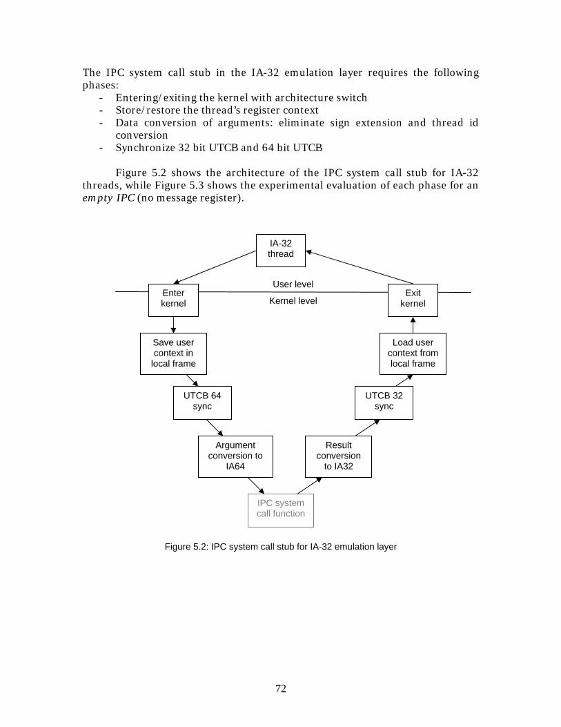
72
Kernel level
IA-32 thread
Result conversion
to IA32
User level
Argument conversion to
IA64
Enter kernel
UTCB 64 sync
Save user context in
local frame
IPC system call function
Load user context from local frame
UTCB 32 sync
Exit kernel
Figure 5.2: IPC system call stub for IA-32 emulation layer
The IPC system call stub in the IA-32 emulation layer requires the following phases:
- Entering/exiting the kernel with architecture switch - Store/restore the thread’s register context - Data conversion of arguments: eliminate sign extension and thread id
conversion - Synchronize 32 bit UTCB and 64 bit UTCB
Figure 5.2 shows the architecture of the IPC system call stub for IA-32
threads, while Figure 5.3 shows the experimental evaluation of each phase for an empty IPC (no message register).
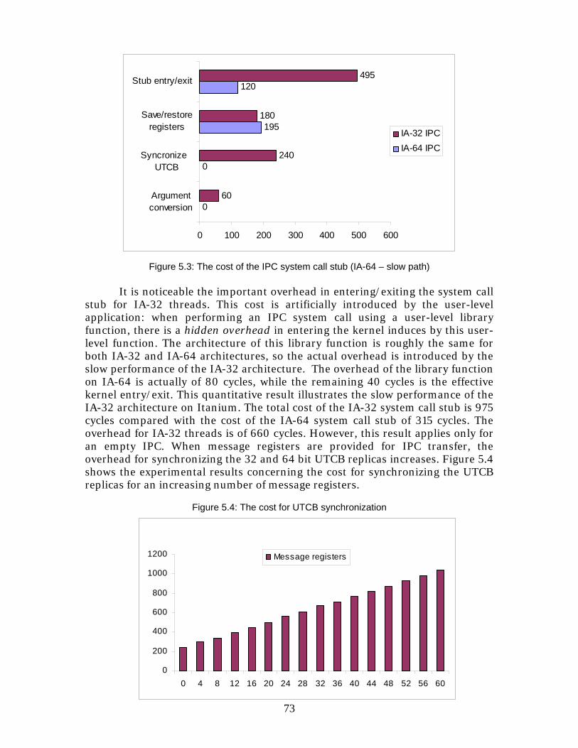
73
0
200
400
600
800
1000
1200
0 4 8 12 16 20 24 28 32 36 40 44 48 52 56 60
Message registers
Figure 5.3: The cost of the IPC system call stub (IA-64 – slow path) It is noticeable the important overhead in entering/exiting the system call
stub for IA-32 threads. This cost is artificially introduced by the user-level application: when performing an IPC system call using a user-level library function, there is a hidden overhead in entering the kernel induces by this user-level function. The architecture of this library function is roughly the same for both IA-32 and IA-64 architectures, so the actual overhead is introduced by the slow performance of the IA-32 architecture. The overhead of the library function on IA-64 is actually of 80 cycles, while the remaining 40 cycles is the effective kernel entry/exit. This quantitative result illustrates the slow performance of the IA-32 architecture on Itanium. The total cost of the IA-32 system call stub is 975 cycles compared with the cost of the IA-64 system call stub of 315 cycles. The overhead for IA-32 threads is of 660 cycles. However, this result applies only for an empty IPC. When message registers are provided for IPC transfer, the overhead for synchronizing the 32 and 64 bit UTCB replicas increases. Figure 5.4 shows the experimental results concerning the cost for synchronizing the UTCB replicas for an increasing number of message registers.
Figure 5.4: The cost for UTCB synchronization
0
0
195
120
60
240
180
495
0 100 200 300 400 500 600
Argumentconversion
Syncronize UTCB
Save/restoreregisters
Stub entry/exit
IA-32 IPCIA-64 IPC
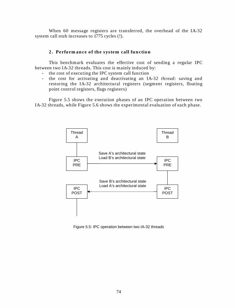
74
When 60 message registers are transferred, the overhead of the IA-32 system call stub increases to 1775 cycles (!).
2. Performance of the system call function This benchmark evaluates the effective cost of sending a regular IPC
between two IA-32 threads. This cost is mainly induced by: - the cost of executing the IPC system call function - the cost for activating and deactivating an IA-32 thread: saving and
restoring the IA-32 architectural registers (segment registers, floating point control registers, flags registers)
Figure 5.5 shows the execution phases of an IPC operation between two
IA-32 threads, while Figure 5.6 shows the experimental evaluation of each phase.
Save A’s architectural state Load B’s architectural state
Thread A
Thread B
IPC PRE
IPC POST
IPC PRE
IPC POST
Figure 5.5: IPC operation between two IA-32 threads
Save B’s architectural state Load A’s architectural state
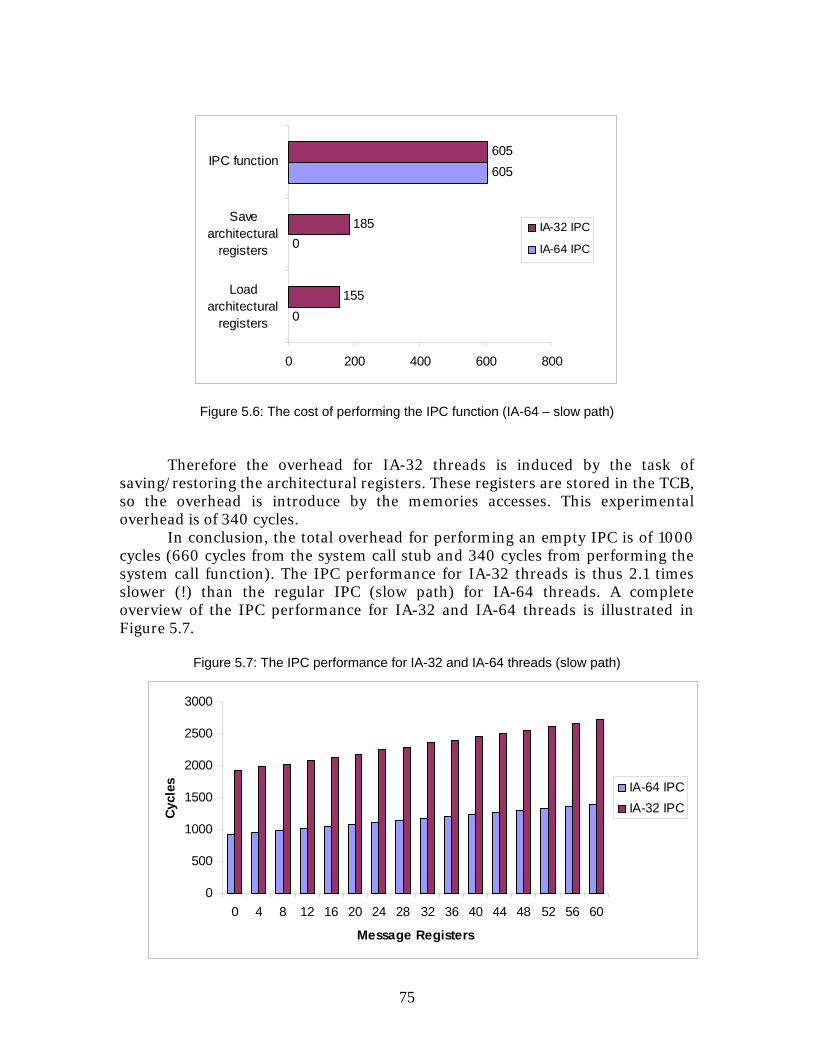
75
0
500
1000
1500
2000
2500
3000
0 4 8 12 16 20 24 28 32 36 40 44 48 52 56 60
Message Registers
Cycl
es IA-64 IPCIA-32 IPC
0
0
605
155
185
605
0 200 400 600 800
Loadarchitectural
registers
Savearchitectural
registers
IPC function
IA-32 IPC
IA-64 IPC
Figure 5.6: The cost of performing the IPC function (IA-64 – slow path) Therefore the overhead for IA-32 threads is induced by the task of saving/restoring the architectural registers. These registers are stored in the TCB, so the overhead is introduce by the memories accesses. This experimental overhead is of 340 cycles. In conclusion, the total overhead for performing an empty IPC is of 1000 cycles (660 cycles from the system call stub and 340 cycles from performing the system call function). The IPC performance for IA-32 threads is thus 2.1 times slower (!) than the regular IPC (slow path) for IA-64 threads. A complete overview of the IPC performance for IA-32 and IA-64 threads is illustrated in Figure 5.7.
Figure 5.7: The IPC performance for IA-32 and IA-64 threads (slow path)
76
By complying with the second design requirement and avoiding performance penalties for the IA-64 threads, the entire performance overhead has been leveraged out on the IA-32 threads. As a consequence, the performance of the slow path IPC for IA-32 threads is considerably lower compared with the native IA-64 IPC system call. An optimization is to provide a fast path IPC for communication between IA-32 threads, which may reduce the performance overhead. To provide a complete optimization of the IPC communication, an additional fast path for communication between IA-32 and IA-64 threads should also be provided. In addition to the IPC system call, all other L4 system calls suffer the same performance overhead for IA-32 threads. This performance overhead can be reduced by providing specific IA-32 implementations of each system call function. This approach is partially taken by Linux IA-64 [4] for system calls raising data incompatibility issues between IA-32 and IA-64. However, in the L4 microkernel, the system call functions are the largest part of the kernel’s code. This approach practically requires rewriting most of the kernel‘s code. This cost can only be justified by a high-usage of IA-32 user-level binaries on the Itanium processor.
77
Chapter 6
Analysis This chapter evaluates the suitability of the theoretical design models discussed in Chapter 3 with respect to the experimental results produced in Chapter 5.
6.1 Functionality vs. Performance
The case study of the L4 microkernel and the Itanium processor shows a kernel-level approach for architectural heterogeneity. The IA-64 kernel was provided with two system interfaces, one for interaction with the IA-64 threads and the other for interaction with IA-32 threads. The implementation showed no performance penalties for the IA-64 threads, while the IA-32 threads experienced an important performance overhead when performing system calls. This overhead is due to design approach: the IA-64 kernel didn’t modify its internal functioning for IA-32 threads, but it instead provided an IA-32 interface to communication with IA-32 threads. This approach leverages an important overhead on IA-32 threads, while the IA-64 threads are not affected. By modifying the IA-64 kernel to access data structures according to IA-32 specifications, the global overhead would have been divided between IA-32 and IA-64 threads. This approach would have reduced the overhead on IA-32 threads considerably, at the expense of IA-64 threads.
The question is whether is possible to communicate across architectural heterogeneity without performance overhead. Considering the first kernel design, native and secondary architectures, user threads of any secondary architecture will suffer performance penalties when invoking the kernel services for communication. This fact is mainly due to data conversion mechanisms performed at interface level between the user thread and the kernel. The second kernel design, equal opportunity, introduces a kernel instance per each architectural state. Communication between two architectural-identical threads can be performed without any overhead, but overhead is introduced when communicating between two heterogeneous threads: arguments of one thread are converted by the IPC function according to data representation of the other thread. In addition, this kernel design implies other requirements which may introduce important performance penalties: coherency mechanisms for global data structures at kernel level. In conclusion, each kernel design introduces a performance overhead for communication across two heterogeneous threads.
A second approach which deserves to be studied is the user-level support for architectural heterogeneity: support for heterogeneous computing is built on top of independent kernel instances. An application knows its specific demands in terms of heterogeneous computing and it may reduce the amount of data
78
conversion and coherency of global structures to the required functionality. However, this solution requires user-level mechanisms for synchronization among user threads without using the kernel’s support. So, there is still no guarantee that performance will increase in this solution. In addition, this solution looses an important functional requirement: unmodified usage of heterogeneous applications. Heterogeneous applications can no longer communicate transparently by invoking the kernel services. They have to be aware of the user-level mechanisms.
There are cases when the functionality is more important than computing performance. Examples include the backward compatibility for a certain architectural state and unmodified usage of user-level binaries of non-native architectures (e.g. Itanium and IA-32). In both cases, the user-level binary cannot adapt its behavior for a different architectural state of the kernel, so the kernel must provide this support. In both cases, the kernel-level approach is the only suitable solution to provide the required functionality.
6.2 The microkernel approach
The case study of L4 microkernel on Itanium processor reveals a useful result: the advantages of microkernel technology in constructing Multi-Architecture Operating Systems. The microkernel technology shows two native characteristics which make them particularly attractive: the minimalism and the uniform communication interface. The minimalism is the result of including in the kernel design only the essential mechanisms to manage the hardware. Less essential services are built on top of the microkernel and execute in user mode. The other approach to kernel technology is the monolithic kernels which integrate all operating system services within the kernel itself. The minimalism of the microkernel technology implies fewer global data structures compared with monolithic kernels. The low amount of global data structures is an important requirement for providing heterogeneity support at kernel level. Each architectural state may have its own kernel instance and due to the low amount of global data structures, the kernel instances may cooperate with reduced performance penalties to provide a global system state. The second advantage of the microkernel technology is the uniform communication interface. Any communication process occurs in a microkernel system through an IPC system call which has the same interface for both kernel and user-level services. The presence of a unique communication interface is extremely important for the construction of a MA/OS. All communication across architectural heterogeneity is performed through this unique communication interface, so only one mechanism to overcome communication heterogeneity is required. Therefore, this microkernel advantage of having one single communication interface is essentially for the construction of a MA/OS.
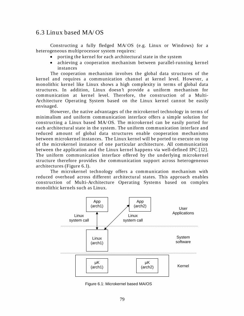
79
6.3 Linux based MA/OS Constructing a fully fledged MA/OS (e.g. Linux or Windows) for a heterogeneous multiprocessor system requires:
• porting the kernel for each architectural state in the system • achieving a cooperation mechanism between parallel-running kernel
instances The cooperation mechanism involves the global data structures of the
kernel and requires a communication channel at kernel level. However, a monolithic kernel like Linux shows a high complexity in terms of global data structures. In addition, Linux doesn’t provide a uniform mechanism for communication at kernel level. Therefore, the construction of a Multi-Architecture Operating System based on the Linux kernel cannot be easily envisaged.
However, the native advantages of the microkernel technology in terms of minimalism and uniform communication interface offers a simple solution for constructing a Linux based MA/OS. The microkernel can be easily ported for each architectural state in the system. The uniform communication interface and reduced amount of global data structures enable cooperation mechanisms between microkernel instances. The Linux kernel will be ported to execute on top of the microkernel instance of one particular architecture. All communication between the application and the Linux kernel happens via well-defined IPC [12]. The uniform communication interface offered by the underlying microkernel structure therefore provides the communication support across heterogeneous architectures (Figure 6.1). The microkernel technology offers a communication mechanism with reduced overhead across different architectural states. This approach enables construction of Multi-Architecture Operating Systems based on complex monolithic kernels such as Linux.
Linux system call
Kernel
Linux system call
Linux
(arch1)
App (arch2)
µK (arch1)
µK (arch2)
Figure 6.1: Microkernel based MA/OS
App (arch1)
System software
User Applications
80
Chapter 7
Conclusions and Future Work
7.1 Summary The objective of this thesis was to develop theoretical design models for constructing an operating system capable of managing multiple architectural states in a tightly-coupled computing system. This design of an operating system is required mainly in the field of heterogeneous computing with direct applications in high-performance embedded systems. The main issues in designing such an operating system are incompatibilities at the binary and data representation levels between different architectural states. The first step in providing a solution for an operating system is a classification of the targeted computing systems. These computing systems were divided in two classes: SPMA (Single Processor/Multi-Architecture) and MPMA (Multi-Processor/Multi-Architecture) systems. Both types of computing systems show similar design models which can be classified in a unified manner. The classification follows two main directions: user-level and kernel-level support for heterogeneity. The user-level support provides independent kernel instances per architectural state and user-level mechanisms to overcome the heterogeneity of the computing systems. The kernel-level support has essentially two design approaches: native and secondary architectures, and equal opportunity. The first approach places the support for architectural heterogeneity at the interface level between the kernel and the user. The kernel is constructed for a single architectural state, while all other system interfaces are “emulated” based on the native system interface. The second approach, equal opportunities, places the support for architectural heterogeneity inside the kernel. Due to binary incompatibility, each architectural state is provided with a kernel instance and all kernel instances cooperate at kernel-level to provide a global system state.
The theoretical models require practical case studies to evaluate their suitability to a specific computing problem. However, the complete implementation of these design models is not an option due to the vast spectrum of solutions, but also to hardware limitations. Therefore, we focused on one particular case study: provide an operating system for the Itanium processor based on the L4 microkernel. The Itanium processor has two architectural states (IA-32 and IA-64). The best suitable theoretical model for this system is the “native and secondary architectures”. This design model is integrated in the L4 microkernel, while respecting two design requirements: operating system transparency for IA-32 user-level binaries and reduced performance overhead for IA-64 user-level binaries. The implementation of the design shows the respect of the initial design requirements, but reveals a side effect: an important
81
performance overhead for IA-32 user-level binaries. Therefore, achieving kernel support for architectural heterogeneity implies certain performance penalties.
7.2 Achievements This thesis focused on defining the field of operating systems designed for tightly-coupled heterogeneous systems. Specific achievements of this thesis include:
• The classification of heterogeneous computing systems based on the number of architectural states in the system and the number of computing nodes
• Proposition of design solutions for constructing Multi-Architecture
Operating Systems
• Design and implementation of a microkernel based operating system for the Itanium processor
7.3 Future work
The first issue which needs further investigation is whether the user-support for architectural heterogeneity may provide better performance results. The kernel approach can always provide a general-purpose solution to architectural heterogeneity, but the user-level approach has the advantage of knowing the specifics of the computing problem and to exploit the architectural heterogeneity for its specific needs while minimizing the performance penalties of managing multiple architectural states.
However, case studies can be found where the kernel-level support for architectural heterogeneity is required. In those cases, an important question concerns the best suitable design for the kernel services. The advantages of the microkernel technology over monolithic kernels make them a promising research direction for developing Multi-Architecture Operating Systems.
82
Bibliography [1] Glenn O.Ladd, Jr. Practical issues in heterogeneous processing systems for military applications. In Proceedings of the 6th Heterogeneous Computing Workshop, pages 162-169, April 1997 [2] Thomas H.Einstein. Mercury Computer Systems’ Modular Heterogeneous RACE® Multicomputer. In Proceedings of the 6th Heterogeneous Computing Workshop, pages 60-71, April 1997 [3] DeQing Chen, Chunqiang Tang, Sandhya Dwarkadas, and Michael L.Scott. Shared State for Heterogeneous Distributed Systems. December 2002 [4] David Mosberger, and Stephane Eranian. IA-64 Linux kernel: design and implementation. Prentice Hall PTR, January 2002 [5] Flynn, M.J. Some computer organizations and their effectiveness. IEEE Transactions on Computers, volume C-21, pages 948-960, September 1972 [6] Ilija Ekmecic, Igor Tartalja, and Veljko Miltutinovic. A survey of heterogeneous computing: concepts and systems. In Proceedings of IEEE, Vol. 84, No. 8, August 1996 [7] Andrew S. Tanenbaum. Modern operating systems Vol.2. Prentice Hall, Inc. June 1997 [8] Intel Corporation. IA-32 Intel® Architecture Software Developer’s Manual Volume 3: System Programming Guide. 2003 [9] Intel Corporation. Intel® Itanium® Architecture Software Developer’s Manual. Volume 1: Application Architecture. Revision 2.1 October 2002 [10] Intel Corporation. Intel® Itanium® Architecture Software Developer’s Manual. Volume 2: System Architecture. Revision 2.1 October 2002 [11] System Architecture Group. L4 Kernel Reference Manual Version X.2. Universität Karlsruhe, June 4 2004. [12] H. Härtig, M. Hohmuth, J. Liedtke, S. Schönberg, and J. Wolter. The performance of µ-kernel-based systems. 16th ACM Symposium on Operating System Principles (SOSP), St. Malo, France, October 1997 [13] J. Liedtke. Improving IPC by kernel design. 14th ACM Symposium on Operating System Principles (SOSP), Asheville, NC, December 1993