Embed Size (px)
Citation preview
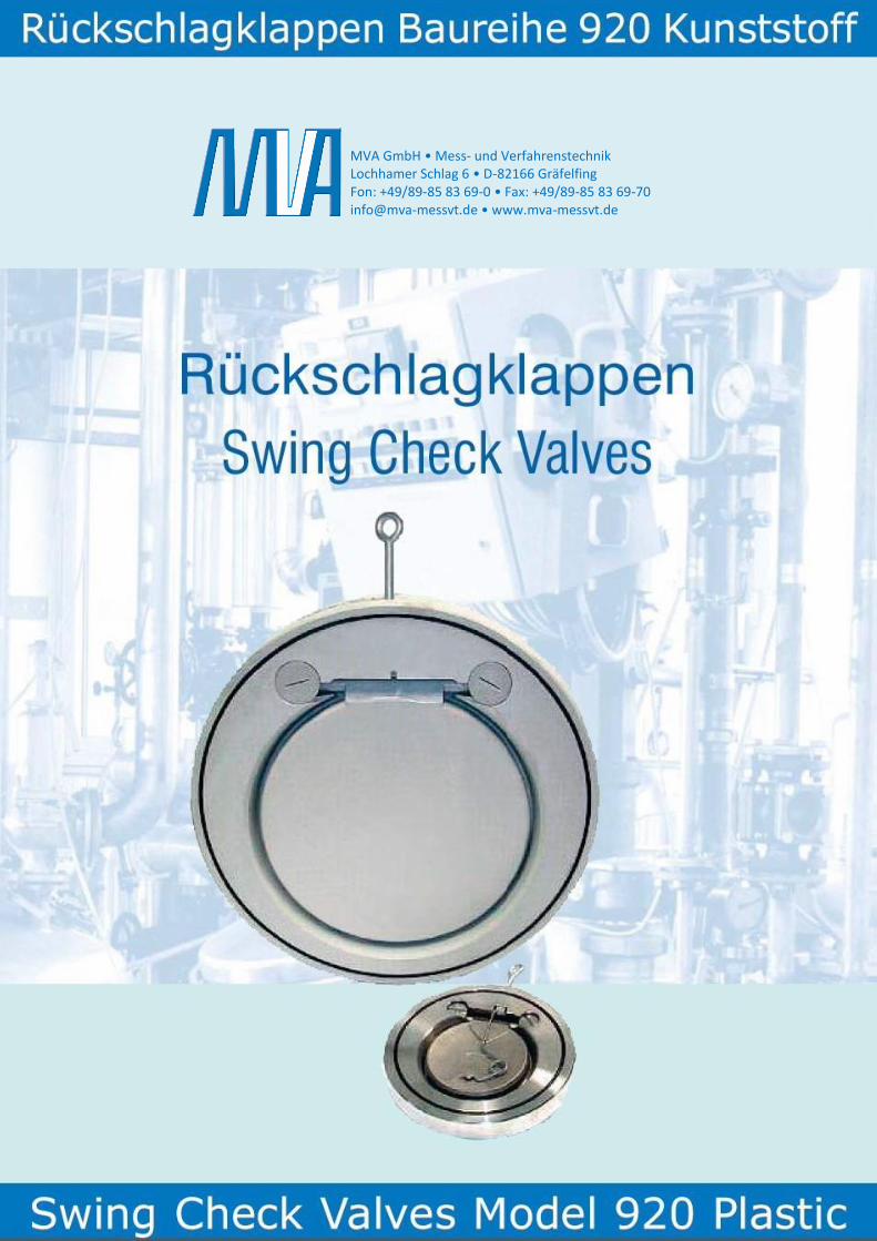
MVA GmbH • Mess- und Verfahrenstechnik Lochhamer Schlag 6 • D-82166 Gräfelfing Fon: +49/89-85 83 69-0 • Fax: +49/89-85 83 69-70 [email protected] • www.mva-messvt.de
2
MVA GmbH Mess- und Verfahrenstechnik Lochhamer Schlag 6 • D-82166 Gräfelfing
Rückschlagklappen 920 Rev.01 0813 DD
Fon: +49/89-85 83 69 -0 • Fax: +49/89-85 83 69 -70 [email protected] • www.mva-messvt.de
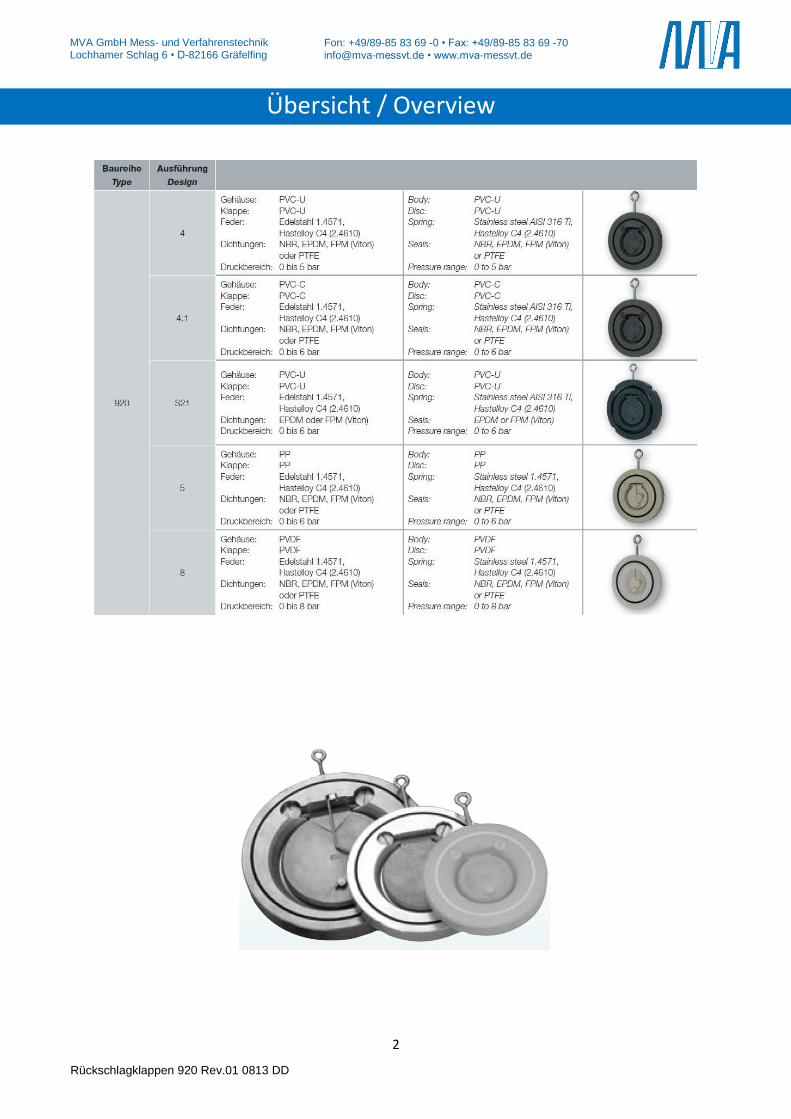
Übersicht / Overview
3
MVA GmbH Mess- und Verfahrenstechnik Lochhamer Schlag 6 • D-82166 Gräfelfing
Rückschlagklappen 920 Rev.01 0813 DD
Fon: +49/89-85 83 69 -0 • Fax: +49/89-85 83 69 -70 [email protected] • www.mva-messvt.de
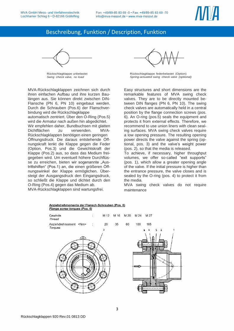
MVA-Rückschlagklappen zeichnen sich durch ihren einfachen Aufbau und ihre kurzen Bau-längen aus. Sie können direkt zwischen DIN-Flansche (PN 6, PN 10) eingebaut werden. Durch die Schrauben (Pos.6) der Flanschver-bindung wird die Rückschlagklappe automatisch zentriert. Über den O-Ring (Pos.5) wird die Armatur nach außen hin abgedichtet. Wir empfehlen daher, Bundbuchsen mit glatten Dichtflächen zu verwenden. MVA-Rückschlagklappen benötigen einen geringen Öffnungsdruck. Die daraus entstehende Öff-nungskraft lenkt die Klappe gegen die Feder (Option, Pos.3) und die Gewichtskraft der Klappe (Pos.2) aus, so dass das Medium frei-gegeben wird. Um eventuell höhere Durchflüs-se zu erreichen, bieten wir sogenannte „Aus-trittshilfen“ (Pos.1) an, die einen größeren Öff-nungswinkel der Klappe ermöglichen. Über-steigt der Ausgangsdruck den Eingangsdruck, so schließt die Klappe und dichtet durch den O-Ring (Pos.4) gegen das Medium ab. MVA-Rückschlagklappen sind wartungsfrei.
Easy structures and short dimensions are the remarkable features of MVA swing check valves. They are to be directly mounted be-tween DIN flanges (PN 6, PN 10). The swing check valves are automatically held in a central position by the flange connection screws (pos. 6). An O-ring (pos.5) seals the equipment and protects it from external effects. Therefore, we recommend to use union liners with clean seal-ing surfaces. MVA swing check valves require a low opening pressure. The resulting opening power directs the valve against the spring (op-tional, pos. 3) and the valve’s weight power (pos. 2), so that the media is released. To achieve, if necessary, higher throughput volumes, we offer so-called “exit supports” (pos. 1), which allow a greater opening angle of the valve. If the initial pressure is higher than the entrance pressure, the valve closes and is sealed by the O-ring (pos. 4) to protect it from the media. MVA swing check valves do not require
maintenance
Rückschlagklappe unbelastet
Swing check valve, no load
Rückschlagklappe federbelastet (Option) Spring-actuated swing check valve (optional)
Beschreibung, Funktion / Description, Funktion
4
MVA GmbH Mess- und Verfahrenstechnik Lochhamer Schlag 6 • D-82166 Gräfelfing
Rückschlagklappen 920 Rev.01 0813 DD
Fon: +49/89-85 83 69 -0 • Fax: +49/89-85 83 69 -70 [email protected] • www.mva-messvt.de
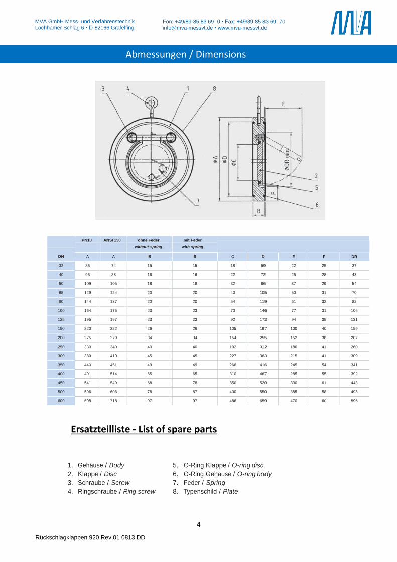
Ersatzteilliste - List of spare parts
1. Gehäuse / Body 5. O-Ring Klappe / O-ring disc
2. Klappe / Disc 6. O-Ring Gehäuse / O-ring body
3. Schraube / Screw 7. Feder / Spring
4. Ringschraube / Ring screw 8. Typenschild / Plate
DN
PN10 ANSI 150 ohne Feder
without spring
mit Feder
with spring
A A B B C D E F DR
32 85 74 15 15 18 59 22 25 37
40 95 83 16 16 22 72 25 28 43
50 109 105 18 18 32 86 37 29 54
65 129 124 20 20 40 105 50 31 70
80 144 137 20 20 54 119 61 32 82
100 164 175 23 23 70 146 77 31 106
125 195 197 23 23 92 173 94 35 131
150 220 222 26 26 105 197 100 40 159
200 275 279 34 34 154 255 152 38 207
250 330 340 40 40 192 312 180 41 260
300 380 410 45 45 227 363 215 41 309
350 440 451 49 49 266 416 245 54 341
400 491 514 65 65 310 467 285 55 392
450 541 549 68 78 350 520 330 61 443
500 596 606 78 87 400 550 385 58 493
600 698 718 97 97 486 659 470 60 595
Abmessungen / Dimensions
5
MVA GmbH Mess- und Verfahrenstechnik Lochhamer Schlag 6 • D-82166 Gräfelfing
Rückschlagklappen 920 Rev.01 0813 DD
Fon: +49/89-85 83 69 -0 • Fax: +49/89-85 83 69 -70 [email protected] • www.mva-messvt.de
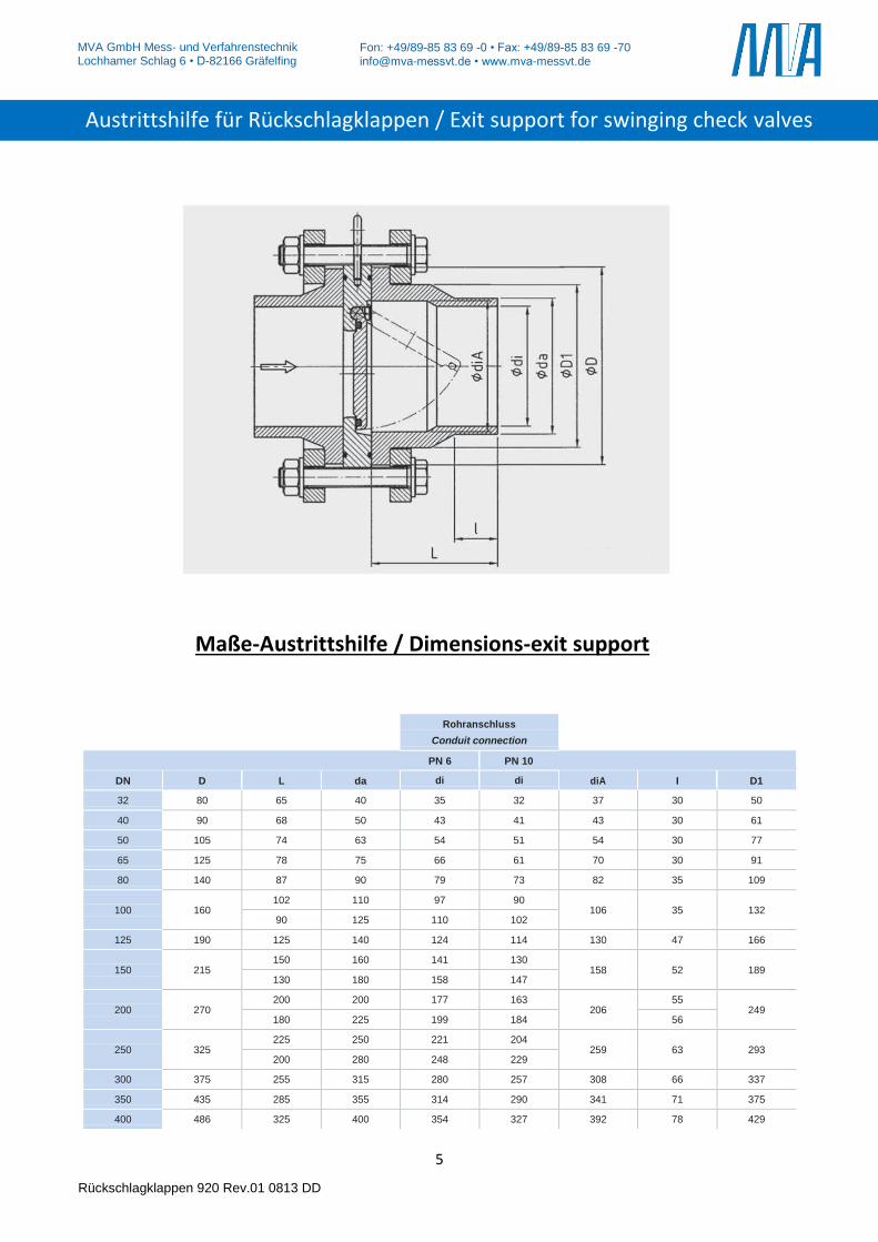
Maße-Austrittshilfe / Dimensions-exit support
Rohranschluss
Conduit connection
PN 6 PN 10 DN D L da di di diA I D1 32 80 65 40 35 32 37 30 50 40 90 68 50 43 41 43 30 61 50 105 74 63 54 51 54 30 77 65 125 78 75 66 61 70 30 91 80 140 87 90 79 73 82 35 109
100
160
102 110 97 90 106
35
132
90 125 110 102 125 190 125 140 124 114 130 47 166
150
215
150 160 141 130 158
52
189
130 180 158 147
200
270 200 200 177 163
206 55
249 180 225 199 184 56
250
325
225 250 221 204 259
63
293
200 280 248 229 300 375 255 315 280 257 308 66 337 350 435 285 355 314 290 341 71 375 400 486 325 400 354 327 392 78 429
Austrittshilfe für Rückschlagklappen / Exit support for swinging check valves
6
MVA GmbH Mess- und Verfahrenstechnik Lochhamer Schlag 6 • D-82166 Gräfelfing
Rückschlagklappen 920 Rev.01 0813 DD
Fon: +49/89-85 83 69 -0 • Fax: +49/89-85 83 69 -70 [email protected] • www.mva-messvt.de
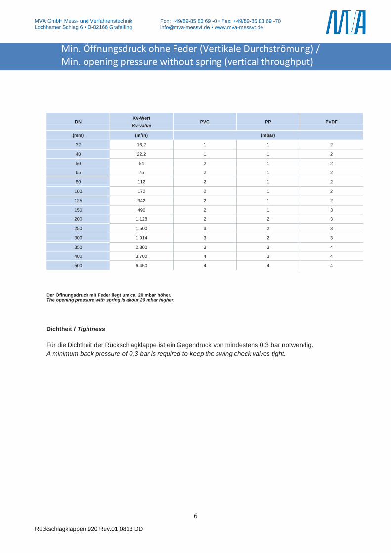
DN
Kv-Wert
Kv-value
PVC
PP
PVDF
(mm) (m3/h) (mbar)
32 16,2 1 1 2
40 22,2 1 1 2
50 54 2 1 2
65 75 2 1 2
80 112 2 1 2
100 172 2 1 2
125 342 2 1 2
150 490 2 1 3
200 1.128 2 2 3
250 1.500 3 2 3
300 1.914 3 2 3
350 2.800 3 3 4
400 3.700 4 3 4
500 6.450 4 4 4
Der Öffnungsdruck mit Feder liegt um ca. 20 mbar höher. The opening pressure with spring is about 20 mbar higher.
Dichtheit / Tightness
Für die Dichtheit der Rückschlagklappe ist ein Gegendruck von mindestens 0,3 bar notwendig.
A minimum back pressure of 0,3 bar is required to keep the swing check valves tight.
Min. Öffnungsdruck ohne Feder (Vertikale Durchströmung) / Min. opening pressure without spring (vertical throughput)
7
MVA GmbH Mess- und Verfahrenstechnik Lochhamer Schlag 6 • D-82166 Gräfelfing
Rückschlagklappen 920 Rev.01 0813 DD
Fon: +49/89-85 83 69 -0 • Fax: +49/89-85 83 69 -70 [email protected] • www.mva-messvt.de
Die unserem Haus in Verbindung.
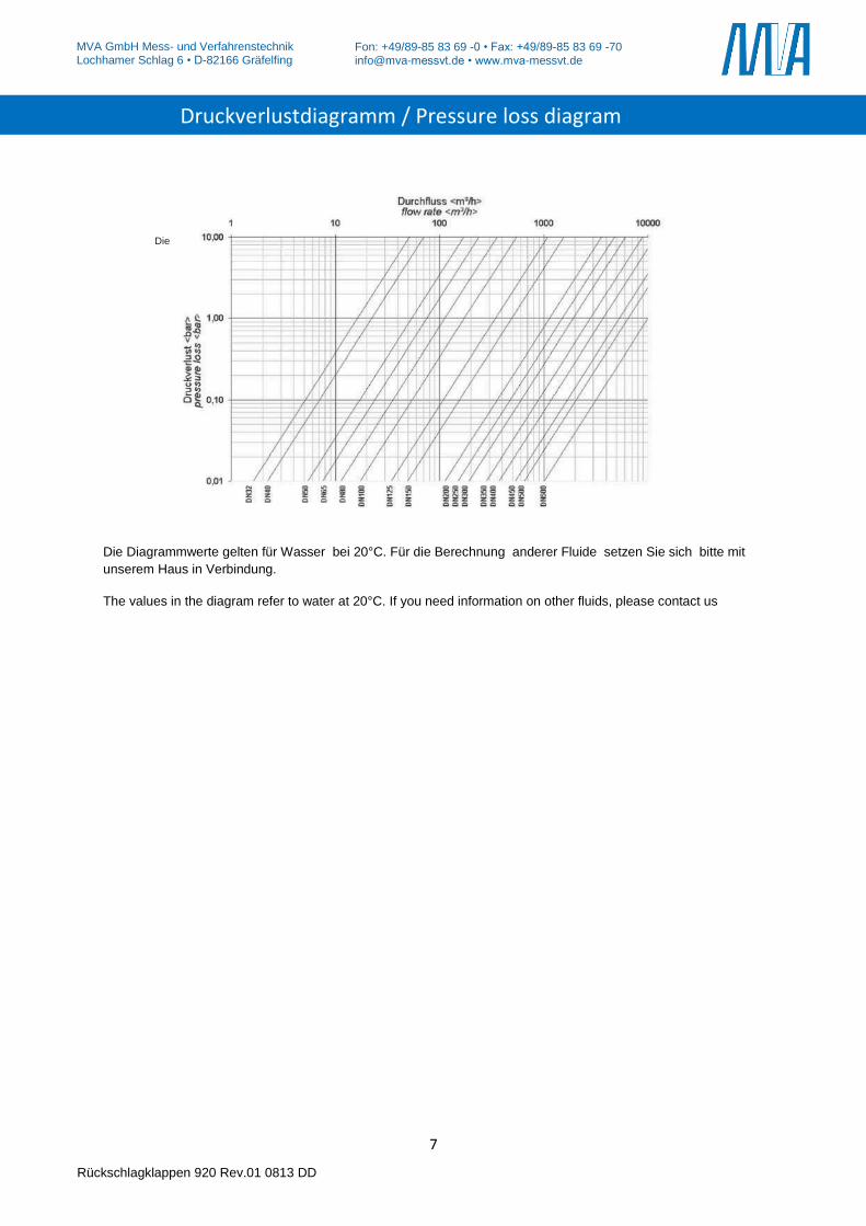
Die Diagrammwerte gelten für Wasser bei 20°C. Für die Berechnung anderer Fluide setzen Sie sich bitte mit
unserem Haus in Verbindung.
The values in the diagram refer to water at 20°C. If you need information on other fluids, please contact us
Druckverlustdiagramm / Pressure loss diagram
8
MVA GmbH Mess- und Verfahrenstechnik Lochhamer Schlag 6 • D-82166 Gräfelfing
Rückschlagklappen 920 Rev.01 0813 DD
Fon: +49/89-85 83 69 -0 • Fax: +49/89-85 83 69 -70 [email protected] • www.mva-messvt.de
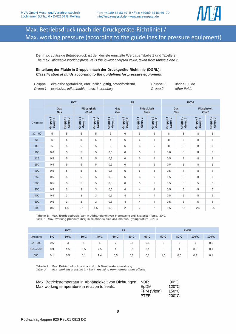
Der max. zulässige Betriebsdruck ist der kleinste ermittelte Wert aus Tabelle 1 und Tabelle 2.
The max. allowable working pressure is the lowest analysed value, taken from tables 1 and 2.
Einteilung der Fluide in Gruppen nach der Druckgeräte-Richtlinie (DGRL):
Classification of fluids according to the guidelines for pressure equipment:
Gruppe 1:
explosionsgefährlich, entzündlich, giftig, brandfördernd Gruppe 2: übrige Fluide Group 1: explosive, inflammable, toxic, incendiary Group 2: other fluids
DN (mm)
PVC PP PVDF
Gas
Gas Flüssigkeit
Fluid Gas
Gas Flüssigkeit
Fluid Gas
Gas Flüssigkeit
Fluid
Gru
pp
e 1
Gro
up
1
Gru
pp
e 2
Gro
up
2
Gru
pp
e 1
Gro
up
1
Gru
pp
e 2
Gro
up
2
Gru
pp
e 1
Gro
up
1
Gru
pp
e 2
Gro
up
2
Gru
pp
e 1
Gro
up
1
Gru
pp
e 2
Gro
up
2
Gru
pp
e 1
Gro
up
1
Gru
pp
e 2
Gro
up
2
Gru
pp
e 1
Gro
up
1
Gru
pp
e 2
Gro
up
2
32 – 50 5 5 5 5 6 6 6 6 8 8 8 8
65 5 5 5 5 6 6 6 6 8 8 8 8
80 5 5 5 5 6 6 6 6 8 8 8 8
100 0,6 5 5 5 0,6 6 6 6 0,6 8 8 8
125 0,5 5 5 5 0,5 6 6 6 0,5 8 8 8
150 0,5 5 5 5 0,5 6 6 6 0,5 8 8 8
200 0,5 5 5 5 0,5 6 6 6 0,5 8 8 8
250 0,5 5 5 5 0,5 6 6 6 0,5 8 8 8
300 0,5 5 5 5 0,5 6 6 6 0,5 5 5 5
350 0,5 3 3 3 0,5 4 4 4 0,5 5 5 5
400 0,5 3 3 3 0,5 4 4 4 0,5 5 5 5
500 0,5 3 3 3 0,5 4 4 4 0,5 5 5 5
600 0,5 1,5 1,5 1,5 0,5 2 2 2 0,5 2,5 2,5 2,5 Tabelle 1: Max. Betriebsdruck (bar) in Abhängigkeit von Nennweite und Material (Temp. 20°C
Table 1: Max. working pressure (bar) in relation to size and material (temperature 20°C)
PVC PP PVDF
DN (mm) 5°C 30°C 50°C 40°C 60°C 80°C 90°C 50°C 80°C 100°C 120°C
32 – 300 0,5 3 1 4 2 0,9 0,5 6 3 1 0,5
350 – 500 0,3 1,5 0,5 2,5 1 0,5 0,1 3 1 0,5 0,1
600 0,1 0,5 0,1 1,4 0,5 0,3 0,1 1,5 0,5 0,3 0,1 Tabelle 2: Max. Betriebsdruck in <bar> durch Temperatureinwirkung
Table 2: Max. working pressure in <bar>, resulting from temperature effects
Max. Betriebstemperatur in Abhängigkeit von Dichtungen: NBR 90°C Max working temperature in relation to seals: EpDM 120°C FPM (Viton) 150°C PTFE 200°C
Max. Betriebsdruck (nach der Druckgeräte-Richtlinie) / Max. working pressure (according to the guidelines for pressure equipment)
9
MVA GmbH Mess- und Verfahrenstechnik Lochhamer Schlag 6 • D-82166 Gräfelfing
Rückschlagklappen 920 Rev.01 0813 DD
Fon: +49/89-85 83 69 -0 • Fax: +49/89-85 83 69 -70 [email protected] • www.mva-messvt.de
1. Bestimmungsgemäße Verwendung
MVA-Rückschlagklappen sind ausschließlich dazu bestimmt,
nach Einbau in ein Rohrleitungssystem Medien innerhalb der
zu- gelassenen Druck- und Temperaturgrenzen einseitig abzu-
sperren (s. Datenblatt). Sie dürfen nur für Medien verwendet
werden, gegen die das Material und die Dichtungen der Rück-
schlagklappe beständig sind. Für Medien mit Feststoffen sind
sie ungeeignet. Die maximale Betriebsdauer beträgt bei Rück-
schlagklappen aus Kunststoff 25 Jahre.
2. Sicherheitshinweise
Allgemeine Sicherheitshinweise Für die Rückschlagklappen gelten dieselben Sicherheitsvor-
schriften wie für das Rohrleitungssystem, in das sie eingebaut
werden.
Anforderungen an den Anwender
Für Rohrleitungssysteme, in denen unsere Rückschlagklap-
pen eingebaut sind, ist der Planer/Installateur und der
Betreiber verantwortlich, dass
die Rückschlagklappe nur wie unter Punkt 1 verwendet wird
das Rohrleitungssystem fachgerecht verlegt ist und dessen Funktion regelmäßig überprüft wird
nur fachlich qualifiziertes Personal die Rückschlag-
klappe einbaut, ausbaut und repariert. Das Personal
muss regel- mäßig in allen zutreffenden Vorschriften
für Arbeitssicherheit und Umweltschutz, insbesonde-
re für druckführende Leitungen unterwiesen werden.
dieses Personal die Betriebsanleitung kennt und die
darin enthaltenen Hinweise beachtet.
Besondere Arten von Gefahren
Vor dem Ausbau der Rückschlagklappe muss der
Druck in der Anlage komplett abgebaut sein, um ein
unkontrolliertes Austreten des Mediums zu vermeiden.
Eventuell sich in der Leitung befindliche Flüssigkeit
muß abgelassen werden. Die beim Ausbau austreten-
de Restflüssigkeit ist aufzufangen. Bei gefährlichen
Restflüssigkeiten oder Gasen notwendige Schutzmaß-
nahmen treffen.
3. Lagerung und Transport
Lagerung:
Rückschlagklappen sind in der Originalver-
packung zu transportieren und an einem
sauberen Ort zu lagern.
Rückschlagklappen enthalten Dichtelemente aus
organischen Werkstoffen, die auf Umwelteinflüsse
reagieren. Sie müssen daher auch möglichst kühl,
trocken und dunkel gelagert werden.
Die Stirnseiten der Rückschlagklappen dürfen
mechanisch nicht beschädigt werden
1. Appropriate use in ac-
cordance to designed
capabilities
MVA swing check valves are designed to block media on one
side of the pipe within allowable pressure and temperature
limits (see data sheet) and to be installed in a pipe system
only. They are only to be used with media, which the material
and the seals are resistant to. They are not suitable for media
with solid components. The maximum life cycle of plastics
swing check valves is 25 years.
2. Safety advices
General safety advices
The safety advices for the pipe system, in which the valves
are to be mounted, are to be followed. The same applies to
the swing check valves.
Demands on the user
In pipe systems, where our swing check valves are to be
used, the planning/installing person and the operator are
responsible for the following issues:
The swing check valves is to be used acor
ing to the regulation in p.1
The pipe system is to be installed
correctly and its operation is to be
checked regularly
The swing check valves is to be mounted, re-
moved and repaired by qualified personnel only.
The staff is to be regularly instructed according to
all relevant regulations concerning working safety
and environmental protection, especially in the
field of pipes under pressure.
These staff members have to be informed about
the manual and the advices included.
Special risks
Before the swing check valve is being removed, pres-
sure has to be completely taken off the plant to avoid
media escaping from the pipe. Fluid being left in the
pipe must be drained off. Fluid, which has remained in
the valve and comes out during removal, is to be col-
lected. If hazardous fluids or gases are left in the valves,
the safety measurements required must be taken.
3. Storage and transport Storage:
Swing check valves are to be transported in
their original packaging and to be stored in a
clean location.
Swing check valves include sealing elements
consisting of organic material, that reacts to
environmental effects. Therefore, they are to
be stored in a place, which is also to be kept
as cool, dry and dark as possible.
The front and back sides of the swing
check valves must not be mechanically
damaged.
Betriebsanleitung Rüchschlagklappen / Perating instruction for swing check valves
10
MVA GmbH Mess- und Verfahrenstechnik Lochhamer Schlag 6 • D-82166 Gräfelfing
Rückschlagklappen 920 Rev.01 0813 DD
Fon: +49/89-85 83 69 -0 • Fax: +49/89-85 83 69 -70 [email protected] • www.mva-messvt.de
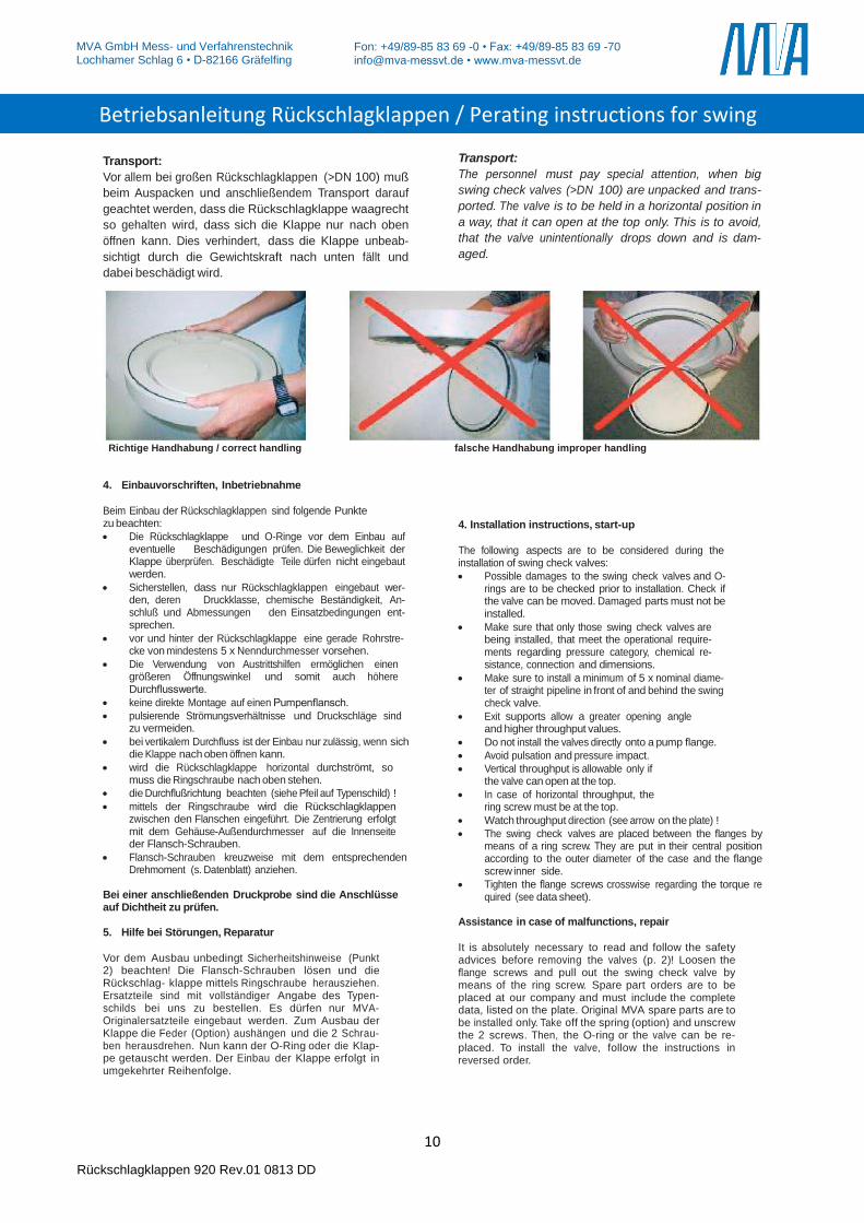
Transport:
Vor allem bei großen Rückschlagklappen (>DN 100) muß
beim Auspacken und anschließendem Transport darauf
geachtet werden, dass die Rückschlagklappe waagrecht
so gehalten wird, dass sich die Klappe nur nach oben
öffnen kann. Dies verhindert, dass die Klappe unbeab-
sichtigt durch die Gewichtskraft nach unten fällt und
dabei beschädigt wird.
Transport:
The personnel must pay special attention, when big
swing check valves (>DN 100) are unpacked and trans-
ported. The valve is to be held in a horizontal position in
a way, that it can open at the top only. This is to avoid,
that the valve unintentionally drops down and is dam-
aged.
Richtige Handhabung / correct handling falsche Handhabung improper handling
4. Einbauvorschriften, Inbetriebnahme
Beim Einbau der Rückschlagklappen sind folgende Punkte zu beachten:
Die Rückschlagklappe und O-Ringe vor dem Einbau auf eventuelle Beschädigungen prüfen. Die Beweglichkeit der Klappe überprüfen. Beschädigte Teile dürfen nicht eingebaut werden.
Sicherstellen, dass nur Rückschlagklappen eingebaut wer-den, deren Druckklasse, chemische Beständigkeit, An-schluß und Abmessungen den Einsatzbedingungen ent-sprechen.
vor und hinter der Rückschlagklappe eine gerade Rohrstre-cke von mindestens 5 x Nenndurchmesser vorsehen.
Die Verwendung von Austrittshilfen ermöglichen einen größeren Öffnungswinkel und somit auch höhere Durchflusswerte.
keine direkte Montage auf einen Pumpenflansch.
pulsierende Strömungsverhältnisse und Druckschläge sind zu vermeiden.
bei vertikalem Durchfluss ist der Einbau nur zulässig, wenn sich die Klappe nach oben öffnen kann.
wird die Rückschlagklappe horizontal durchströmt, so muss die Ringschraube nach oben stehen.
die Durchflußrichtung beachten (siehe Pfeil auf Typenschild) !
mittels der Ringschraube wird die Rückschlagklappen zwischen den Flanschen eingeführt. Die Zentrierung erfolgt mit dem Gehäuse-Außendurchmesser auf die Innenseite der Flansch-Schrauben.
Flansch-Schrauben kreuzweise mit dem entsprechenden Drehmoment (s. Datenblatt) anziehen.
Bei einer anschließenden Druckprobe sind die Anschlüsse auf Dichtheit zu prüfen. 5. Hilfe bei Störungen, Reparatur
Vor dem Ausbau unbedingt Sicherheitshinweise (Punkt 2) beachten! Die Flansch-Schrauben lösen und die Rückschlag- klappe mittels Ringschraube herausziehen. Ersatzteile sind mit vollständiger Angabe des Typen-schilds bei uns zu bestellen. Es dürfen nur MVA-Originalersatzteile eingebaut werden. Zum Ausbau der Klappe die Feder (Option) aushängen und die 2 Schrau-ben herausdrehen. Nun kann der O-Ring oder die Klap-pe getauscht werden. Der Einbau der Klappe erfolgt in umgekehrter Reihenfolge.
4. Installation instructions, start-up
The following aspects are to be considered during the installation of swing check valves:
Possible damages to the swing check valves and O-rings are to be checked prior to installation. Check if the valve can be moved. Damaged parts must not be installed.
Make sure that only those swing check valves are being installed, that meet the operational require-ments regarding pressure category, chemical re-sistance, connection and dimensions.
Make sure to install a minimum of 5 x nominal diame-ter of straight pipeline in front of and behind the swing check valve.
Exit supports allow a greater opening angle and higher throughput values.
Do not install the valves directly onto a pump flange.
Avoid pulsation and pressure impact.
Vertical throughput is allowable only if the valve can open at the top.
In case of horizontal throughput, the ring screw must be at the top.
Watch throughput direction (see arrow on the plate) !
The swing check valves are placed between the flanges by means of a ring screw. They are put in their central position according to the outer diameter of the case and the flange screw inner side.
Tighten the flange screws crosswise regarding the torque re quired (see data sheet).
Assistance in case of malfunctions, repair
It is absolutely necessary to read and follow the safety advices before removing the valves (p. 2)! Loosen the flange screws and pull out the swing check valve by means of the ring screw. Spare part orders are to be placed at our company and must include the complete data, listed on the plate. Original MVA spare parts are to be installed only. Take off the spring (option) and unscrew the 2 screws. Then, the O-ring or the valve can be re-placed. To install the valve, follow the instructions in reversed order.
Betriebsanleitung Rückschlagklappen / Perating instructions for swing
check valves
11
MVA GmbH Mess- und Verfahrenstechnik Lochhamer Schlag 6 • D-82166 Gräfelfing
Rückschlagklappen 920 Rev.01 0813 DD
Fon: +49/89-85 83 69 -0 • Fax: +49/89-85 83 69 -70 [email protected] • www.mva-messvt.de
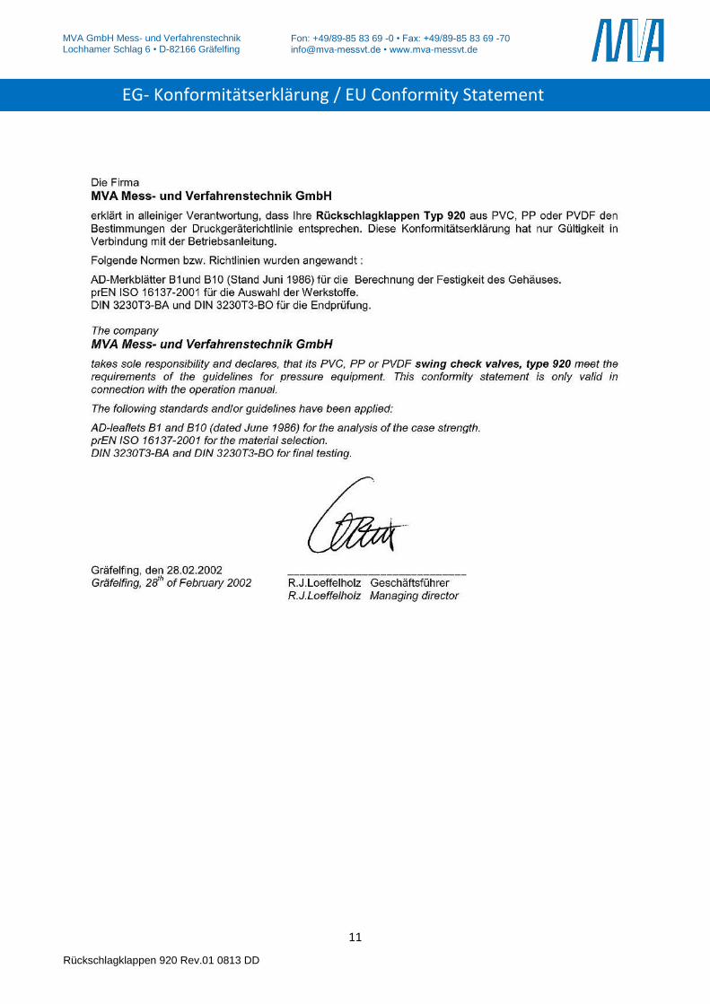
EG- Konformitätserklärung / EU Conformity Statement
12
MVA GmbH Mess- und Verfahrenstechnik Lochhamer Schlag 6 • D-82166 Gräfelfing
Rückschlagklappen 920 Rev.01 0813 DD
Fon: +49/89-85 83 69 -0 • Fax: +49/89-85 83 69 -70 [email protected] • www.mva-messvt.de
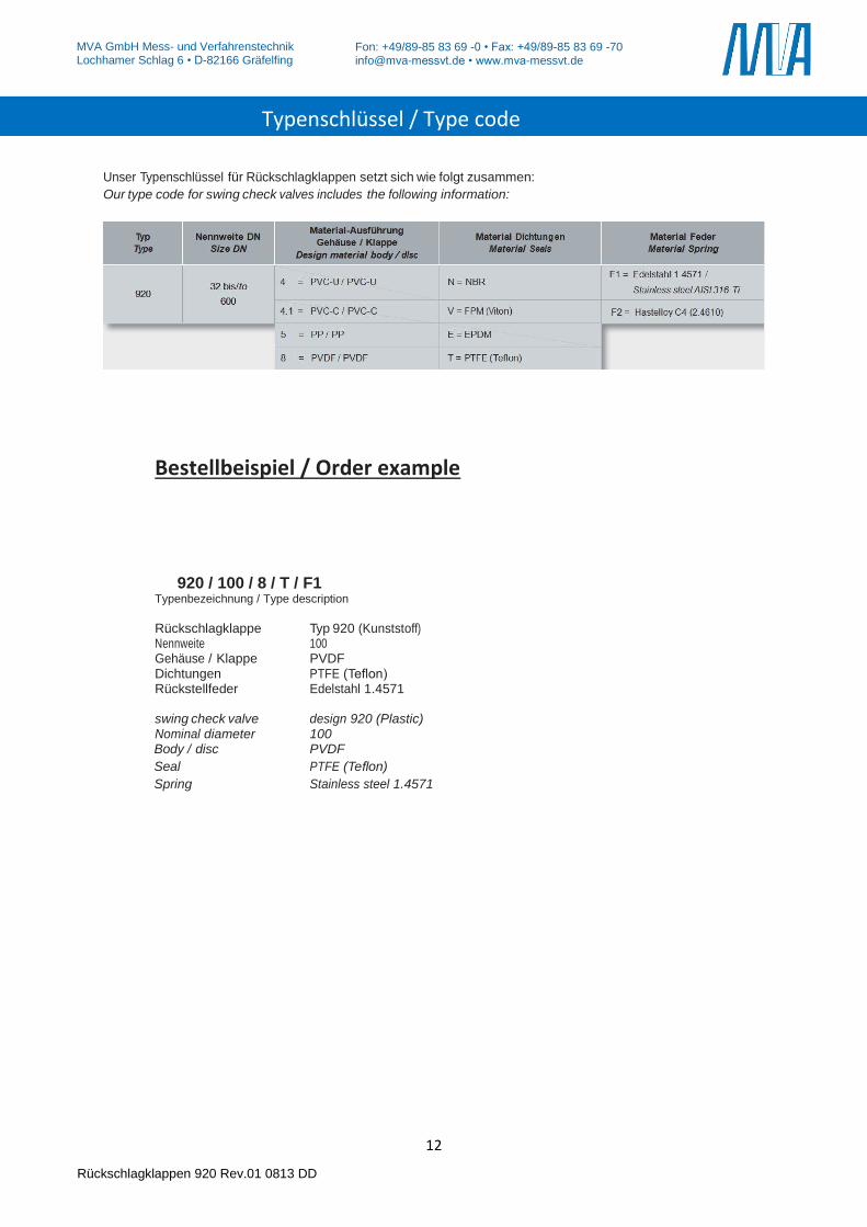
Unser Typenschlüssel für Rückschlagklappen setzt sich wie folgt zusammen:
Our type code for swing check valves includes the following information:
Bestellbeispiel / Order example 920 / 100 / 8 / T / F1 Typenbezeichnung / Type description
Rückschlagklappe Typ 920 (Kunststoff) Nennweite 100 Gehäuse / Klappe PVDF Dichtungen PTFE (Teflon) Rückstellfeder Edelstahl 1.4571 swing check valve design 920 (Plastic) Nominal diameter 100
Body / disc PVDF
Seal PTFE (Teflon)
Spring Stainless steel 1.4571
Typenschlüssel / Type code