Embed Size (px)
Citation preview

DLR Center of Excellence Composite Structures
NDT-Verfahren zur Qualitätskontrolle und für in-serviceInspektionen von Composite- und integralen
FlugzeugstrukturenDr. Wolfgang Hillger, Thomas Ullmann
Werkstoffkolloquium 2006Luftfahrzeugstrukturen der Zukunft – Wettbewerb der Werkstoffe
05. 12. 2006, DLR Köln
2DLR Center of Excellence Composite Structures
Übersicht
EinleitungUltraschallprüftechnik
AnforderungenBildgebungAnkopplungstechnikenPrüfung von FSW- AluminiumlegierungenAnkopplung mit Luft
SHM mit Acousto UltrasonicsProjekteVisualisierung der Wellenausbreitung
ZusammenfassungComputerthomografie

3DLR Center of Excellence Composite Structures
Einleitung
• Definition zerstörungsfrei: Spätere Verwendung wird nicht beeinträchtigt • Vor 100 Jahren: Beginn der ZfP, Conrad Röntgen entdeckt die X-
Strahlen• Die ZfP gehört zu den wichtigsten Methoden der sicherheitstechnischen
Überwachung, vergleichbar mit der medizinischen Diagnostik• Qualitätskontrolle und Qualitätssicherung• Vermeidung von Unfällen• Fehlstellen werden indirekt angezeigt • Aufgabe der ZfP: Aus Änderungen physikalischer Messwerte auf
Fehlstellen im Werkstoff schließen• Interpretation: Fehler oder nur Ungänzen• ZfP ist ein relatives Verfahren, muss durch Vergleichskörper mit
definierten Fehlstellen kalibriert werden
4DLR Center of Excellence Composite Structures
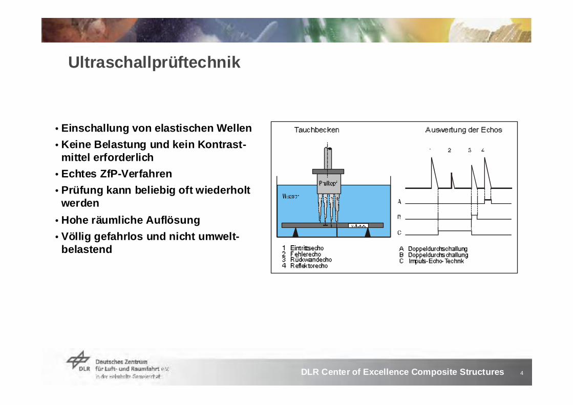
Ultraschallprüftechnik
• Einschallung von elastischen Wellen• Keine Belastung und kein Kontrast-
mittel erforderlich• Echtes ZfP-Verfahren• Prüfung kann beliebig oft wiederholt
werden• Hohe räumliche Auflösung• Völlig gefahrlos und nicht umwelt-
belastend

5DLR Center of Excellence Composite Structures
Introduction (2)The use of composites for primary and secondary structures of aerospace vehicles requires a powerful non-destructive testing(NDT) after production and in service
Typical defects to detect:PorosityImpact damagesDebonding of skin and core in sandwich components
6DLR Center of Excellence Composite Structures
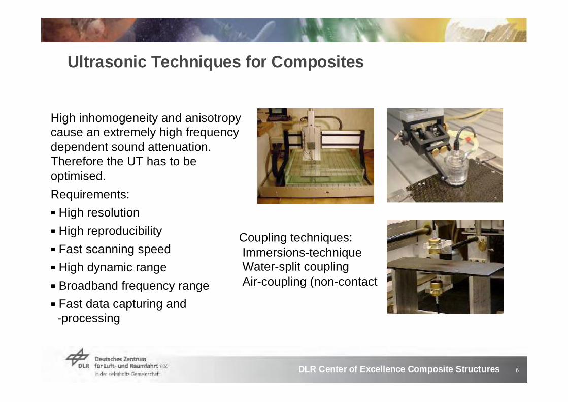
Ultrasonic Techniques for Composites
High inhomogeneity and anisotropycause an extremely high frequency dependent sound attenuation. Therefore the UT has to be optimised.Requirements:
High resolutionHigh reproducibilityFast scanning speedHigh dynamic rangeBroadband frequency rangeFast data capturing and -processing
Coupling techniques:Immersions-techniqueWater-split couplingAir-coupling (non-contact

7DLR Center of Excellence Composite Structures
CFRP: High and frequency-dependent Sound Attenuation
50 mm thick CFRP5 mm thick CFRP
Fmax = 1.7 MHz Fmax = 1.0 MHz
CFRP-step wedge
Important:Optimised amplitude distance control (ADC)

8DLR Center of Excellence Composite Structures
Ultrasonic Imaging

9DLR Center of Excellence Composite Structures
High Resolution Ultrasonic Imaging Systems at DLR
Technical data HFUS 2XXX
Full-wave A-scansData recording:
400 mm / sScanning speed:
12,5 µmMech. resolution:
1000 x 1500 mmScanning area:
50 dB in A-ScanDynamic range:
A-, B-, C-, D and F-scansImaging:
8-14 bit / 1000 MS/sADC:
up to 30 kHzPRF:
0.001 to 120 MHz (-3dB)Frequency range:
B-scan of a 2 mm thick CFRP-specimen

10DLR Center of Excellence Composite Structures
Rejected CFPR Component, Thickness: 4 to 34 mm

11DLR Center of Excellence Composite Structures
Inspection of curved CFRP-Panels
12DLR Center of Excellence Composite Structures
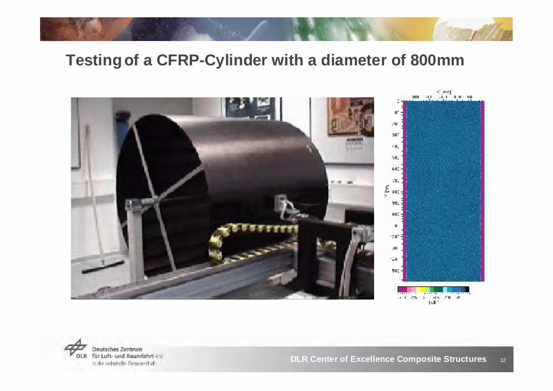
Testing of a CFRP-Cylinder with a diameter of 800mm
13DLR Center of Excellence Composite Structures
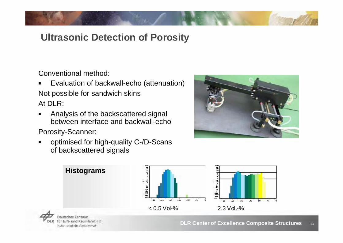
Ultrasonic Detection of Porosity
Conventional method:Evaluation of backwall-echo (attenuation)
Not possible for sandwich skins At DLR:
Analysis of the backscattered signal between interface and backwall-echo
Porosity-Scanner:optimised for high-quality C-/D-Scans of backscattered signals
< 0.5 Vol-% 2.3 Vol.-%
Histograms

14DLR Center of Excellence Composite Structures
Detection of Cracks and Delaminations in CFRP
C-sans of the backwall- and flaw-echo after loading in fatigue

15DLR Center of Excellence Composite Structures
Indication of Waviness of Fibres

16DLR Center of Excellence Composite Structures
Phased Array Technik (Gruppenstrahler)
• Prüfköpfe bestehen aus bis zu 128 Elementen
• Phasengesteuerte Ansteuerung beim Sender und Empfänger
• Schnelles (elektronisches) Scannen: linear, Sektor- und Tiefenscan
• Variables Schallfeld bezüglich Fokus und Winkel
• Real-Time B- Bild

17DLR Center of Excellence Composite Structures
Ultraschall Gruppenstrahler
Winkeleinschallung Fokussierunglineares Scannen
Segmentierte Schwinger im Prüfkopf erlauben ‚Programmierung‘ des Prüfkopfes:
schnelle Bildgebung Schweißnähte dicke Bauteile
18DLR Center of Excellence Composite Structures
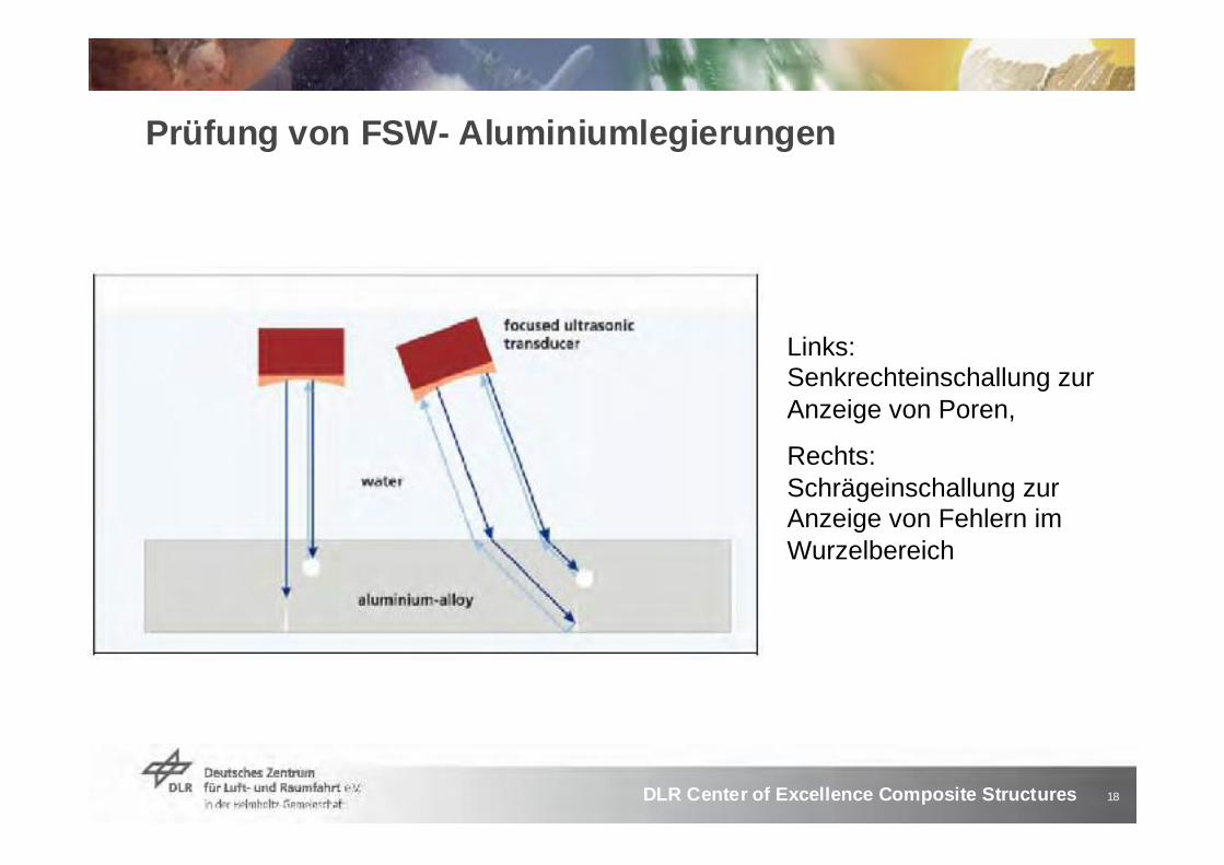
Prüfung von FSW- Aluminiumlegierungen
Links:Senkrechteinschallung zur Anzeige von Poren,
Rechts:Schrägeinschallung zur Anzeige von Fehlern im Wurzelbereich

19DLR Center of Excellence Composite Structures
Poren in der FSW-Naht
B-Bild SchliffbildQuelle: T. Vugrin et al., Non-destructive detection of flaws in FSW and their metallographic characterization, 5th International FSW Symposium, Metz, France, 2004

20DLR Center of Excellence Composite Structures
Anzeige von FSW-Wurzelfehlern
Wurzelfehler
D-Bild
Quelle: T. Vugrin et al., Non-destructive detection of flaws in FSW and their metallographic characterization,
5th International FSW Symposium, Metz, France, 2004
21DLR Center of Excellence Composite Structures
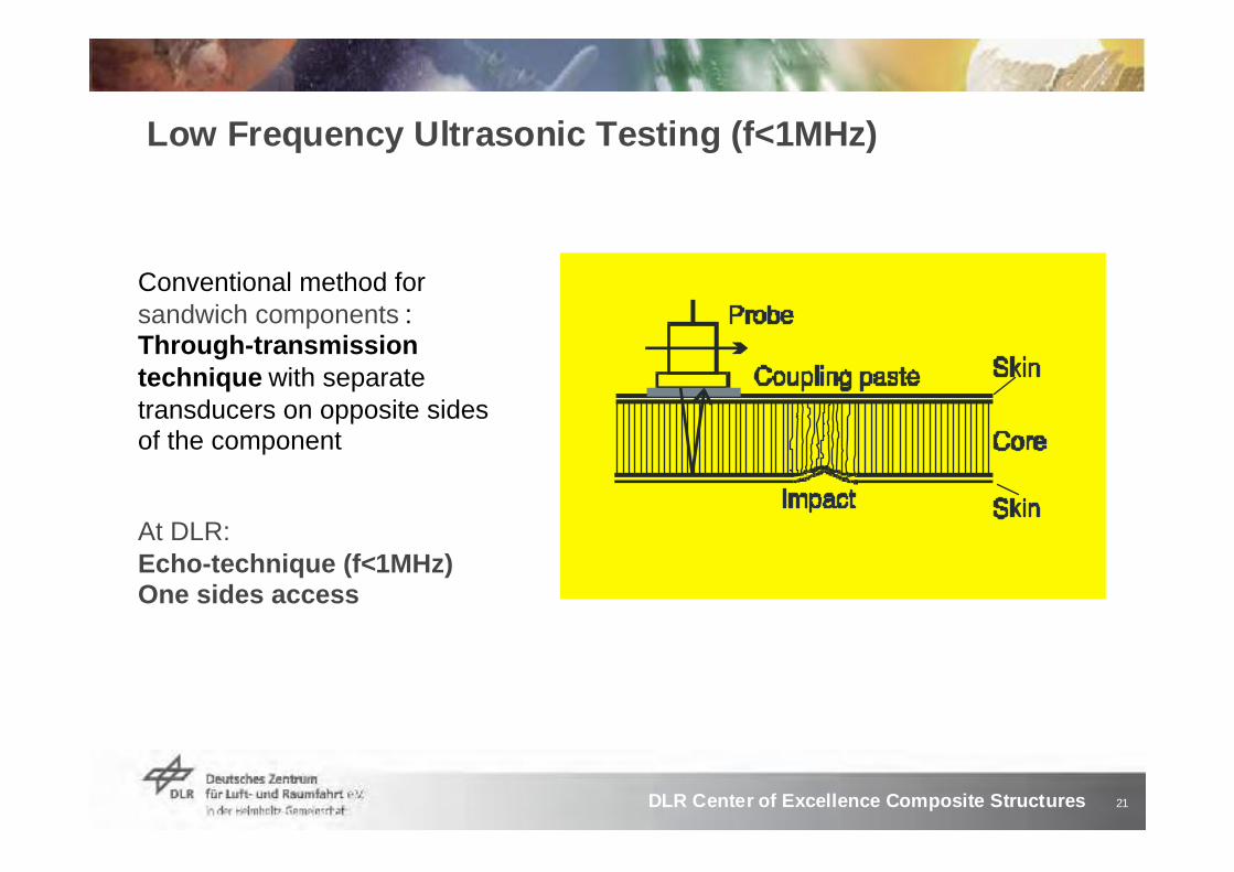
Low Frequency Ultrasonic Testing (f<1MHz)
Conventional method for sandwich components :Through-transmissiontechnique with separate transducers on opposite sides of the component
At DLR:Echo-technique (f<1MHz)One sides access

22DLR Center of Excellence Composite Structures
Ultrasonic Imaging for Defects in curved Components
• The MUSE system provides in-field inspections
• C-and D-Imaging show defectsizes and locations
Inspection of a tail-unit cut out of a helicopter using the Mobile UltraSonic Equipment (MUSE)

23DLR Center of Excellence Composite Structures
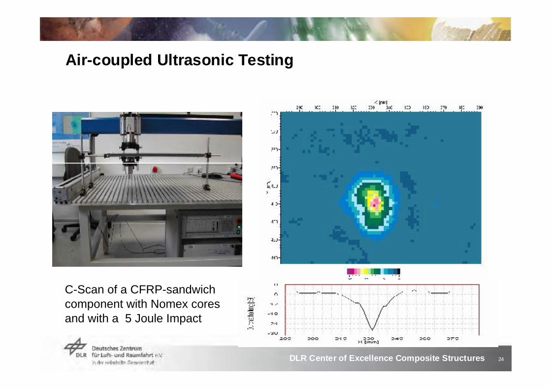
Non-contact Ultrasonic Inspection with Air-Coupling
Air-coupled technique easily provides ultrasonic inspectionswithout coupling liquid or couplingpasteHigh acoustic impedance mismatchbetween air and solids
Requirements:• Special transducers with several
matching layers to air• Ultrasonic system with a high power
burst transmitter• Ultra low-noise preamplifier• Analogue and digital signal processing• Data recording and image processing
24DLR Center of Excellence Composite Structures
Air-coupled Ultrasonic Testing
C-Scan of a CFRP-sandwich component with Nomex cores and with a 5 Joule Impact
25DLR Center of Excellence Composite Structures
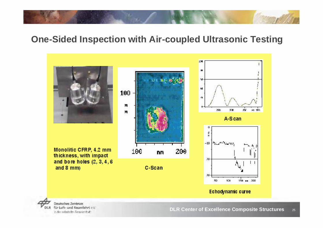
One-Sided Inspection with Air-coupled Ultrasonic Testing

26DLR Center of Excellence Composite Structures
Motivation for Guided Wave Techniques
• In order to take advantage of the special properties of composites, new CFRP components will get more and more complex
• It will not be able to test these structures in service with standard NDT-methods
• The costs for in-service inspections must be downcast
27DLR Center of Excellence Composite Structures
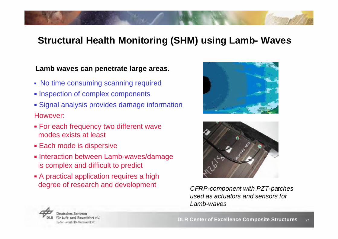
No time consuming scanning requiredInspection of complex componentsSignal analysis provides damage information
However:For each frequency two different wave modes exists at least Each mode is dispersiveInteraction between Lamb-waves/damageis complex and difficult to predictA practical application requires a highdegree of research and development CFRP-component with PZT-patches
used as actuators and sensors for Lamb-waves
Lamb waves can penetrate large areas.
Structural Health Monitoring (SHM) using Lamb- Waves

28DLR Center of Excellence Composite Structures
Lamb wave modes
Symmetric (S0)Lamb wave modes
Anti-symmetric (A0)Lamb wave mode
Source:http://www.me.sc.edu/Research/lamss/research/Waves/ewaves.htm

29DLR Center of Excellence Composite Structures
SHM: Permanent vorhandene Sensoren/Aktuatoren
Source: http://www.g-netz.de/Der_Mensch/nervensystem/index.shtml
Source: Airbus Bremen
Sensor-Netzwerk

30DLR Center of Excellence Composite Structures
EU-Project AISHA
AISHA: Aircraft integrated structural health assessmentDLR-contribution with 4 PJValidation of calculated Lamb-Wave ModesExcitation and analysis of Lamb-Waves Reliability / durability of sensors/actuators under environmental stressInvestigation of CFRP - and sandwich-specimensComparison of Lamb-Wave Techniques with ultrasonic imagingFull scale test of a helicopter tail unit

31DLR Center of Excellence Composite Structures
DLR Wettbewerb der Visionen
Selbst überwachende und selbst heilende Strukturen
Intelligente, multifunktionale Faserverbundleichtbaustrukturen durch Integrierte:Mess- und Prüfsysteme zur Last- und Schadenserkennung(Multifunktionale Fasern: Lasttragend und Sensoren (TsAGI, Moskau))Integrierte Reparatursysteme zur Selbstheilung
erhöhen die Sicherheit und senken die Betriebskosten.
Lars Herbeck, Wolfgang Hillger, Boris Kolesnikov, Tobias Ströhlein

32DLR Center of Excellence Composite Structures
Time of flight at six Positions of Sandwich Specimens
33DLR Center of Excellence Composite Structures
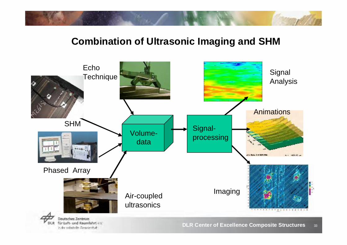
Volume-data
Animations
SignalAnalysis
Imaging
Phased Array
EchoTechnique
SHM Signal-processing
Combination of Ultrasonic Imaging and SHM
Air-coupledultrasonics

34DLR Center of Excellence Composite Structures
Ultrasonic System USPC 5000 for Lamb Wave Testing
• Both guided waves (Lamb waves)and ultrasonic imaging techniques
• 8 transmitters and 8 receivers generate 64 cycles
• The data logger provides automatic on-line testing
35DLR Center of Excellence Composite Structures
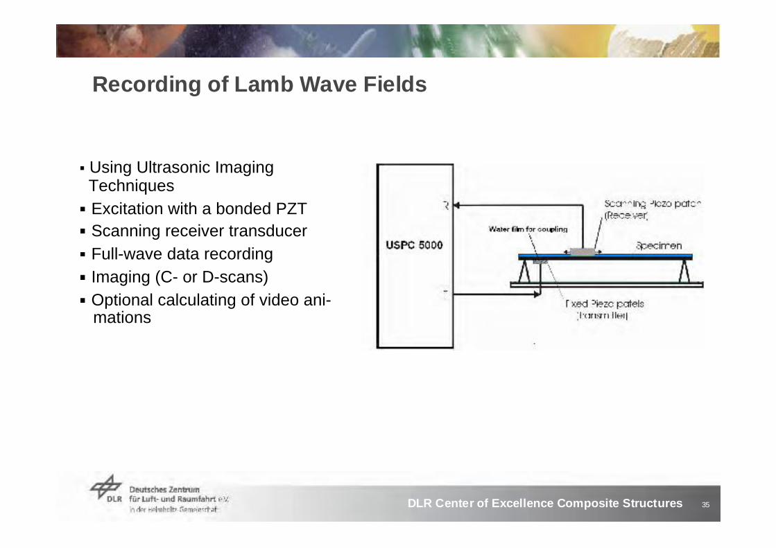
Recording of Lamb Wave Fields
Using Ultrasonic ImagingTechniquesExcitation with a bonded PZTScanning receiver transducerFull-wave data recordingImaging (C- or D-scans)Optional calculating of video ani-mations
36DLR Center of Excellence Composite Structures
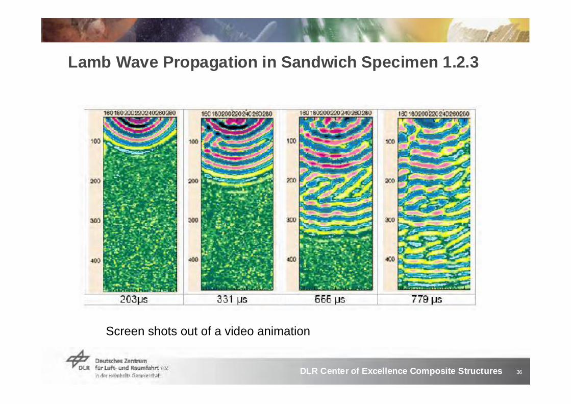
Lamb Wave Propagation in Sandwich Specimen 1.2.3
Screen shots out of a video animation

37DLR Center of Excellence Composite Structures
US- and Lamb wave testing of monolithic Specimens
Specimen 383 0 Joule
Specimen 36420 Joule
Lamb wave responses, f = 47 kHzC- scans, f= 10 MHz

38DLR Center of Excellence Composite Structures
Interaction between Lamb-Waves and Damages
Ultrasonic C-scan(pulse-echo, back wall
echo)
Transmitter
Hole
HoleDelamination• Typical effect of damageon wave propagation:
– Time delay– Decrease in amplitude– Reflections– Interferences– Mode conversions
A B
C
Lamb-wave visualisation (Calculated out of experimental data)

39DLR Center of Excellence Composite Structures
Wave Propagation between Stringers
D-scans of wave propagation using two and three actuators
40DLR Center of Excellence Composite Structures
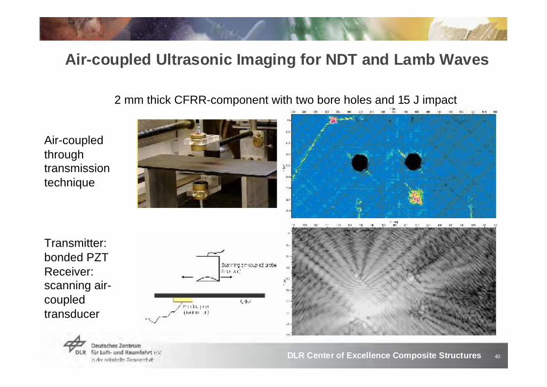
Air-coupled Ultrasonic Imaging for NDT and Lamb Waves
Air-coupledthroughtransmissiontechnique
Transmitter:bonded PZTReceiver:scanning air-coupledtransducer
2 mm thick CFRR-component with two bore holes and 15 J impact

41DLR Center of Excellence Composite Structures
Impedance Spectroscopy for the control of the acoustic coupling between PZT and Component
Back: free air operationRed: water coupledBlue: gluedGreen: glued 10 min.
“Back Box“ USB-device C-60 for impedance measurements

42DLR Center of Excellence Composite Structures
Future Activities
Full scale test: Tail unit of the EC 135
CFRP-component with a monolithic and a sandwich part Length: 3.40 m Max. width: 0.45 m
Lamb wave testing during loading in fatigueSource: Eurocopter

43DLR Center of Excellence Composite Structures
Zusammenfassung
Die hohe Inhomogenität und Anisotropie von CFK-Komponenten bewirkt eine hohe Schallschwächung und –Streuung. Daher sind spezielle Anpassungen erforderlich.Unterschiedliche Ankoppeltechniken: Tauchtechnik, Wasserspaltankopplung, und berührungslos mit Ankopplung über LuftDie Ergebnisse zeigen eine hohe Auflösung und Reproduzierbarkeit, sogar Poren können angezeigt werden.Allerdings ist das Scannen zeitaufwendigZukünftige Bauteile sind zu komplex für Standart NDT Techniken
SHM : Globales automatisches Inspektionssystem Lamb-Wellen können sich über große Bereiche ausbreiten Bei einer Frequenz gibt es mehrere WellenmodenKenntnis der Interaktion zwischen der Wellenausbreitung und den FehlstellenVisualisierung der Wellenausbreitung mit bildgebender US-TechnikOptimierung der Placierung von Aktuatoren und Sensoren
44DLR Center of Excellence Composite Structures
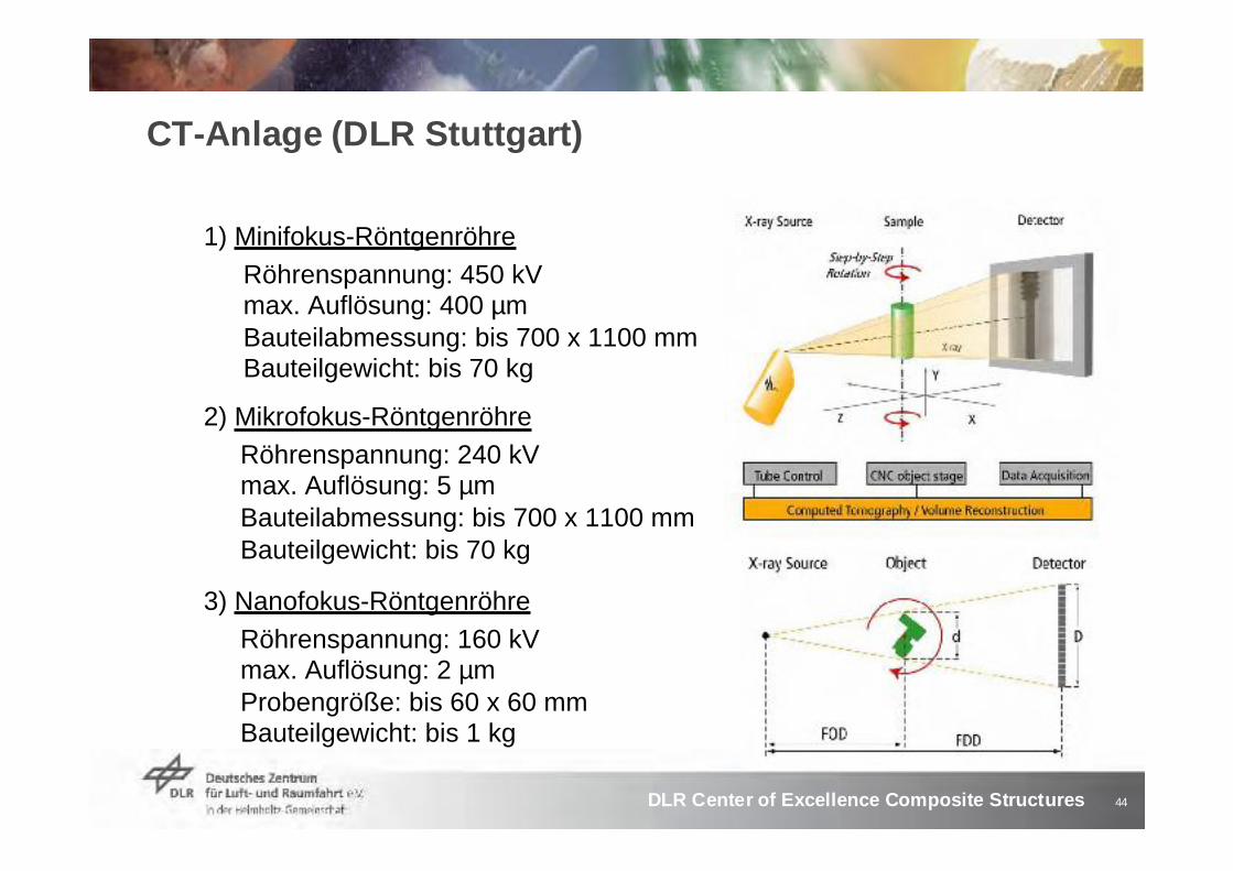
CT-Anlage (DLR Stuttgart)
1) Minifokus-Röntgenröhre Röhrenspannung: 450 kVmax. Auflösung: 400 µmBauteilabmessung: bis 700 x 1100 mmBauteilgewicht: bis 70 kg
2) Mikrofokus-Röntgenröhre Röhrenspannung: 240 kVmax. Auflösung: 5 µmBauteilabmessung: bis 700 x 1100 mmBauteilgewicht: bis 70 kg
3) Nanofokus-RöntgenröhreRöhrenspannung: 160 kVmax. Auflösung: 2 µmProbengröße: bis 60 x 60 mmBauteilgewicht: bis 1 kg
45DLR Center of Excellence Composite Structures
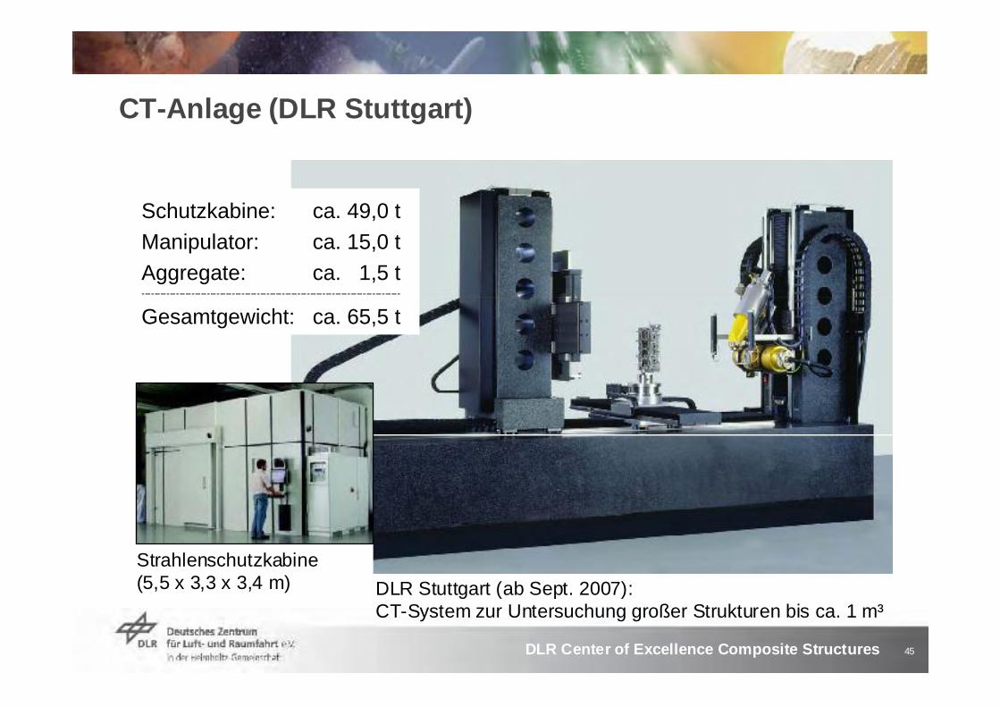
CT-Anlage (DLR Stuttgart)
Schutzkabine: ca. 49,0 tManipulator: ca. 15,0 tAggregate: ca. 1,5 t-----------------------------------------------------------------------------------
Gesamtgewicht: ca. 65,5 t
Strahlenschutzkabine(5,5 x 3,3 x 3,4 m) DLR Stuttgart (ab Sept. 2007):
CT-System zur Untersuchung großer Strukturen bis ca. 1 m³
46DLR Center of Excellence Composite Structures
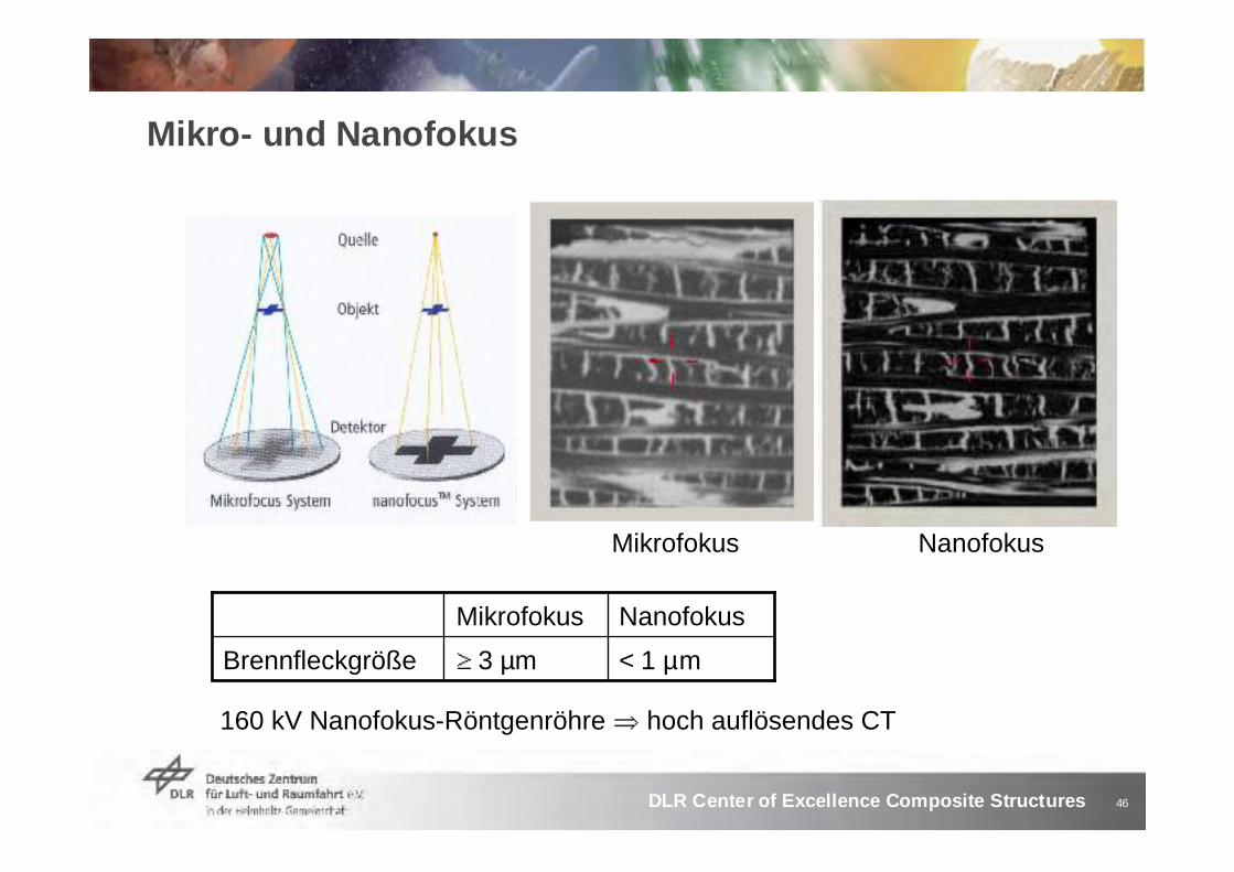
Mikrofokus
Mikro- und Nanofokus
< 1 µm3 µmBrennfleckgröße
NanofokusMikrofokus
160 kV Nanofokus-Röntgenröhre hoch auflösendes CT
Nanofokus

47DLR Center of Excellence Composite Structures
CT als Element der Bauteiloptimierung I
Bauteiloptimierung (Loop)
Herstellung
Bauteil
3D-Analysedurch CT
Bauteiltests
Bauteildesign
gezielte Untersuchung und Bewertungversagenskritischer Stellen im Bauteil
Keramischer Niet aus C/C-SiC
AVI

48DLR Center of Excellence Composite Structures
CT als Element der Bauteiloptimierung II
Bauteiloptimierung (Loop)
Herstellung
Bauteil
3D-Analysedurch CT
Bauteiltests
Bauteildesign
zahlreiche Risse im CFK-Flansch deuten auf eine versagenskritische Stelle hin
SimulationFEM-Modelle
Keramische Brennkammer
AVI

49DLR Center of Excellence Composite Structures
CT zur Optimierung von Schadensmodellen
3D-Daten der CT-Analyse ergänzen numerische Ansätze zur Schadensmodellierung
Verfahrens-optimierung
Bauteil
3D-Analysedurch CT
Simulationdurch FEM
Schadens-modellierung
Bauteiltest
Unterstützung bei Schadensmodellierung

50DLR Center of Excellence Composite Structures
Untersuchungen an Bauteilen und Proben von BK
CFK-Sandwich (Mikrofokus)
1.) Probenfoto (oben),2.) Röntgentransmission (rechts oben), 3.) CT-Bild (Falschfarbe, rechts unten) AVI
1
2
3

51DLR Center of Excellence Composite Structures
CT als Prozessglied in der Strukturenentwicklung
Herstellung
Material-entwicklung
Bauteil-entwicklung
Struktur-entwicklung
Material Bauteil Struktur
3D-Analyse(CT)
3D-Analyse(CT)
3D-Analyse(CT)
Numerik(FEM-Simulation)
Numerik(FEM-Simulation)
Numerik(FEM-Simulation)
1. 2. 3.
3-dimensionale CT-Analysen ergänzen die Datenbasis für numerische Simulationen bei der Werkstoffentwicklung sowie bei Design und Konstruktion von Bauteilen und neuartigen Strukturkonzepten

52DLR Center of Excellence Composite Structures
Vielen Dank für Ihre Aufmerksamkeit