Embed Size (px)
Citation preview
II - 98 RK Rose+Krieger GmbH & Co. KG � Postfach 15 64 � D-32375 Minden
Nutensteine, Schrauben und ZubehörSlot stones, screws and accessories
Nutensteine,Schrauben und ZubehörSlot stones,screws andaccessories
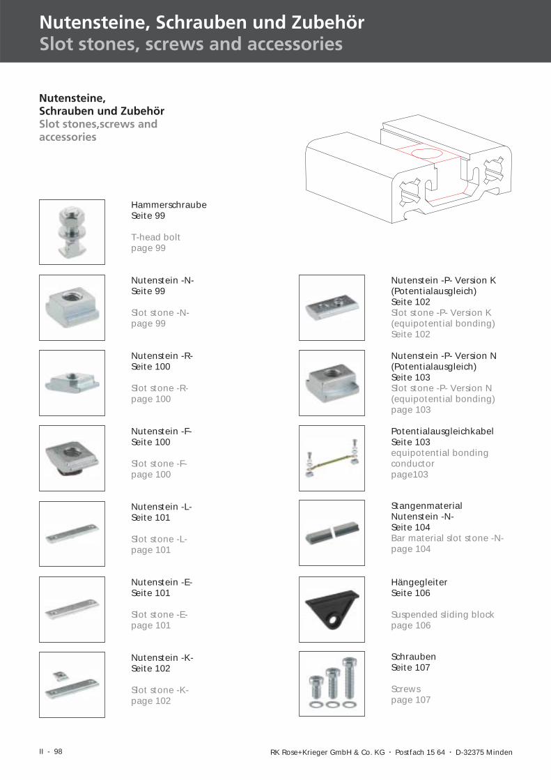
HammerschraubeSeite 99
T-head boltpage 99
Nutenstein -N-Seite 99
Slot stone -N-page 99
Nutenstein -R-Seite 100
Slot stone -R-page 100
Nutenstein -F-Seite 100
Slot stone -F-page 100
Nutenstein -P- Version K(Potentialausgleich)Seite 102Slot stone -P- Version K(equipotential bonding)Seite 102
Nutenstein -K-Seite 102
Slot stone -K-page 102
Nutenstein -L-Seite 101
Slot stone -L-page 101
Nutenstein -E-Seite 101
Slot stone -E-page 101
Nutenstein -P- Version N(Potentialausgleich)Seite 103Slot stone -P- Version N(equipotential bonding)page 103
PotentialausgleichkabelSeite 103equipotential bondingconductorpage103
StangenmaterialNutenstein -N-Seite 104Bar material slot stone -N-page 104
HängegleiterSeite 106
Suspended sliding blockpage 106
SchraubenSeite 107
Screwspage 107
II - 99
R K R OS E K R I EG E R+I
II
IV
III
V
VID-BL 08/2005
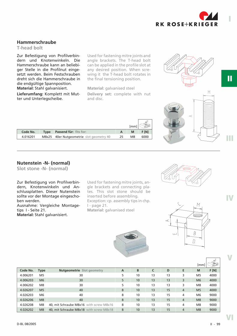
Zur Befestigung von Profilverbin-dern und Knotenwinkeln. DieHammerschraube kann an beliebi-ger Stelle in die Profilnut einge-setzt werden. Beim Festschraubendreht sich die Hammerschraube indie endgültige Spannposition.Material: Stahl galvanisiert.Lieferumfang: Komplett mit Mut-ter und Unterlegscheibe.
Zur Befestigung von Profilverbin-dern, Knotenwinkeln und An-schlussplatten. Dieser Nutensteinsollte vor der Montage eingescho-ben werden.Ausnahme: Vergleiche Montage-tips I - Seite 21.Material: Stahl galvanisiert.
Nutenstein -N- (normal)Slot stone -N- (normal)
HammerschraubeT-head bolt
Used for fastening mitre joints andangle brackets. The T-head boltcan be applied in the profile slot atany desired position. When scre-wing it the T-head bolt rotates inthe final tensioning position.
Material: galvanised steelDelivery set: complete with nutand disc.
Used for fastening mitre joints, an-gle brackets and connecting pla-tes. This slot stone should beinserted before assembling.Exception: cp. assembly tips in chp.I - page 21.Material: galvanised steel
Code No. Type Passend für: fits for: A M F [N]
4.016201 M8x25 40er Nutgeometrie slot geometry 40 25 M8 6000
Code No. Type Nutgeometrie Slot geometry A B C D E M F [N]
4.006201 M5 30 5 10 13 13 3 M5 4000
4.006203 M6 30 5 10 13 13 3 M6 4000
4.006202 M8 30 5 10 13 13 3 M8 4000
4.026207 M5 40 8 10 13 15 4 M5 4000
4.026203 M6 40 8 10 13 15 4 M6 9000
4.026206 M8 40 8 10 13 15 4 M8 9000
4.026208 M8 40, mit Schraube M8x16 with screw M8x16 8 10 13 15 4 M8 9000
4.026202 M8 40, mit Schraube M8x18 with screw M8x18 8 10 13 15 4 M8 9000
[mm]
[mm]
II - 100 RK Rose+Krieger GmbH � Postfach 15 64 � D-32375 Minden
Code No. Type Passend für: fits for: A B C M F [N]
4.006222 M5 30er Nutgeometrie slot geometry 30 13 5 10 M5 4000
4.006221 M6 30er Nutgeometrie slot geometry 30 13 5 10 M6 4000
4.006223 M8 30er Nutgeometrie slot geometry 30 13 5 10 M8 4000
4.026221 M6 40er Nutgeometrie slot geometry 40 15 9 10 M6 8000
4.026222 M8 40er Nutgeometrie slot geometry 40 15 9 10 M8 8000
Code No. Type Passend für: fits for: A B C M F [N]
4.006710 M3 alle all 10 12 4 M3 3000
4.006716 M4 alle all 10 12 4 M4 3500
4.006711 M5 alle all 10 12 4 M5 4000
4.006712 M6 alle all 10 12 4 M6 4500
4.006715 M4 40er Nutgeometrie slot geometry 40 10 14 4 M4 3500
4.006713 M5 40er Nutgeometrie slot geometry 40 10 14 4 M5 4000
4.006714 M6 40er Nutgeometrie slot geometry 40 10 14 4 M6 4500
[mm]
[mm]
Nutensteine, Schrauben und ZubehörSlot stones, screws and accessories
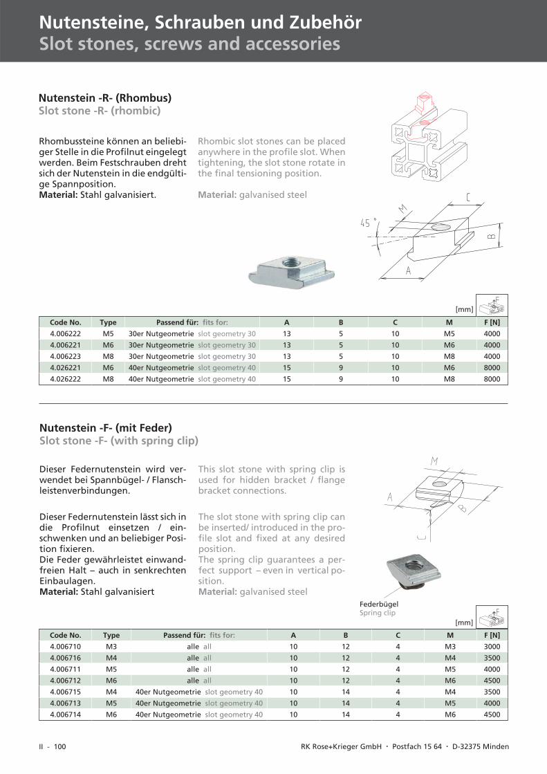
Rhombussteine können an beliebi-ger Stelle in die Profilnut eingelegtwerden. Beim Festschrauben drehtsich der Nutenstein in die endgülti-ge Spannposition.Material: Stahl galvanisiert.
Nutenstein -R- (Rhombus)Slot stone -R- (rhombic)
Rhombic slot stones can be placedanywhere in the profile slot. Whentightening, the slot stone rotate inthe final tensioning position.
Material: galvanised steel
Dieser Federnutenstein lässt sich indie Profilnut einsetzen / ein-schwenken und an beliebiger Posi-tion fixieren.Die Feder gewährleistet einwand-freien Halt – auch in senkrechtenEinbaulagen.Material: Stahl galvanisiert
Nutenstein -F- (mit Feder)Slot stone -F- (with spring clip)
FederbügelSpring clip
Dieser Federnutenstein wird ver-wendet bei Spannbügel- / Flansch-leistenverbindungen.
The slot stone with spring clip canbe inserted/ introduced in the pro-file slot and fixed at any desiredposition.The spring clip guarantees a per-fect support – even in vertical po-sition.Material: galvanised steel
This slot stone with spring clip isused for hidden bracket / flangebracket connections.
II - 101
I
II
IV
III
V
VID-BL 10/2003
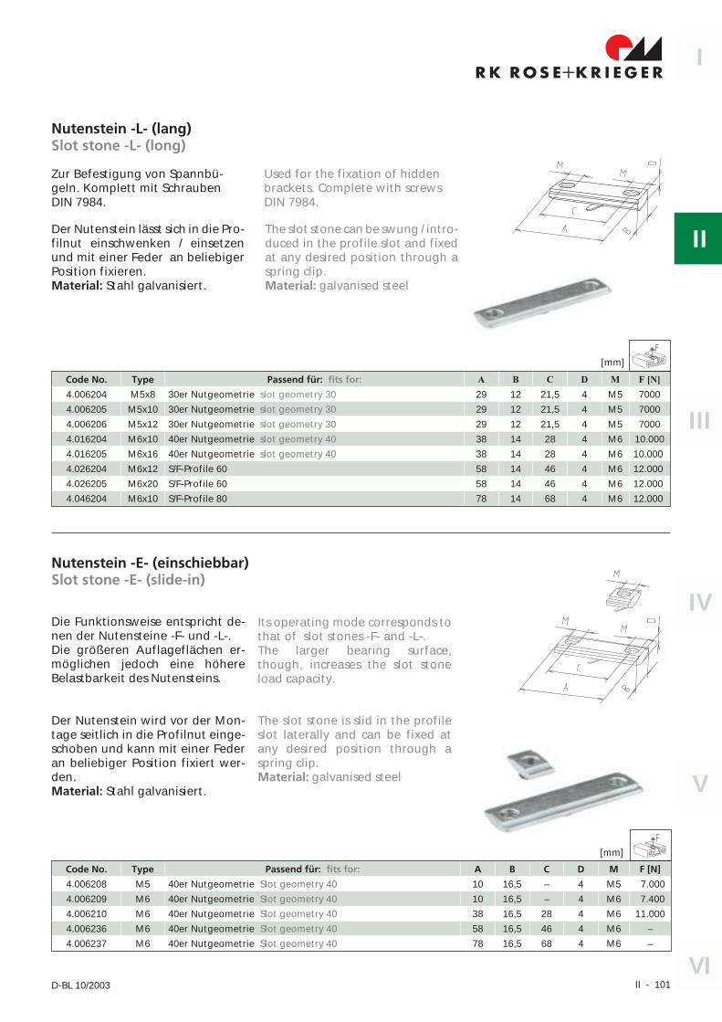
Der Nutenstein lässt sich in die Pro-filnut einschwenken / einsetzenund mit einer Feder an beliebigerPosition fixieren.Material: Stahl galvanisiert.
Nutenstein -L- (lang)Slot stone -L- (long)
Zur Befestigung von Spannbü-geln. Komplett mit SchraubenDIN 7984.
Code No. Type Passend für: fits for: A B C D M F [N]
4.006204 M5x8 30er Nutgeometrie slot geometry 30 29 12 21,5 4 M5 7000
4.006205 M5x10 30er Nutgeometrie slot geometry 30 29 12 21,5 4 M5 7000
4.006206 M5x12 30er Nutgeometrie slot geometry 30 29 12 21,5 4 M5 7000
4.016204 M6x10 40er Nutgeometrie slot geometry 40 38 14 28 4 M6 10.000
4.016205 M6x16 40er Nutgeometrie slot geometry 40 38 14 28 4 M6 10.000
4.026204 M6x12 S/F-Profile 60 58 14 46 4 M6 12.000
4.026205 M6x20 S/F-Profile 60 58 14 46 4 M6 12.000
4.046204 M6x10 S/F-Profile 80 78 14 68 4 M6 12.000
The slot stone can be swung / intro-duced in the profile slot and fixedat any desired position through aspring clip.Material: galvanised steel
Used for the fixation of hiddenbrackets. Complete with screwsDIN 7984.
Nutenstein -E- (einschiebbar)Slot stone -E- (slide-in)
Die Funktionsweise entspricht de-nen der Nutensteine -F- und -L-.Die größeren Auflageflächen er-möglichen jedoch eine höhereBelastbarkeit des Nutensteins.
Der Nutenstein wird vor der Mon-tage seitlich in die Profilnut einge-schoben und kann mit einer Federan beliebiger Position fixiert wer-den.Material: Stahl galvanisiert.
Code No. Type Passend für: fits for: A B C D M F [N]
4.006208 M5 40er Nutgeometrie Slot geometry 40 10 16,5 – 4 M5 7.000
4.006209 M6 40er Nutgeometrie Slot geometry 40 10 16,5 – 4 M6 7.400
4.006210 M6 40er Nutgeometrie Slot geometry 40 38 16,5 28 4 M6 11.000
4.006236 M6 40er Nutgeometrie Slot geometry 40 58 16,5 46 4 M6 –
4.006237 M6 40er Nutgeometrie Slot geometry 40 78 16,5 68 4 M6 –
Its operating mode corresponds tothat of slot stones -F- and -L-.The larger bearing surface,though, increases the slot stoneload capacity.
The slot stone is slid in the profileslot laterally and can be fixed atany desired position through aspring clip.Material: galvanised steel
[mm]
[mm]
II - 102 RK Rose+Krieger GmbH & Co. KG � Postfach 15 64 � D-32375 Minden
Nutensteine, Schrauben und ZubehörSlot stones, screws and accessories
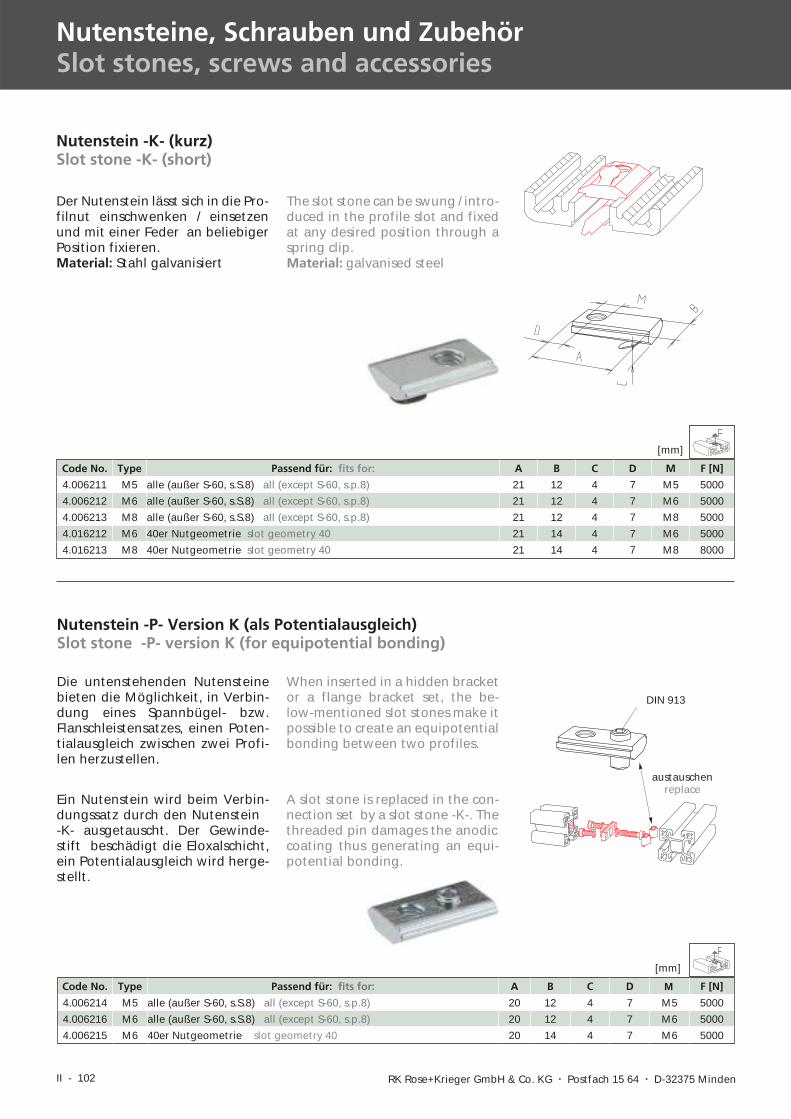
Der Nutenstein lässt sich in die Pro-filnut einschwenken / einsetzenund mit einer Feder an beliebigerPosition fixieren.Material: Stahl galvanisiert
Nutenstein -K- (kurz)Slot stone -K- (short)
Code No. Type Passend für: fits for: A B C D M F [N]
4.006211 M5 alle (außer S-60, s.S.8) all (except S-60, s.p.8) 21 12 4 7 M5 5000
4.006212 M6 alle (außer S-60, s.S.8) all (except S-60, s.p.8) 21 12 4 7 M6 5000
4.006213 M8 alle (außer S-60, s.S.8) all (except S-60, s.p.8) 21 12 4 7 M8 5000
4.016212 M6 40er Nutgeometrie slot geometry 40 21 14 4 7 M6 5000
4.016213 M8 40er Nutgeometrie slot geometry 40 21 14 4 7 M8 8000
Nutenstein -P- Version K (als Potentialausgleich)Slot stone -P- version K (for equipotential bonding)
Die untenstehenden Nutensteinebieten die Möglichkeit, in Verbin-dung eines Spannbügel- bzw.Flanschleistensatzes, einen Poten-tialausgleich zwischen zwei Profi-len herzustellen.
DIN 913
Ein Nutenstein wird beim Verbin-dungssatz durch den Nutenstein-K- ausgetauscht. Der Gewinde-stift beschädigt die Eloxalschicht,ein Potentialausgleich wird herge-stellt.
austauschenreplace
Code No. Type Passend für: fits for: A B C D M F [N]
4.006214 M5 alle (außer S-60, s.S.8) all (except S-60, s.p.8) 20 12 4 7 M5 5000
4.006216 M6 alle (außer S-60, s.S.8) all (except S-60, s.p.8) 20 12 4 7 M6 5000
4.006215 M6 40er Nutgeometrie slot geometry 40 20 14 4 7 M6 5000
The slot stone can be swung / intro-duced in the profile slot and fixedat any desired position through aspring clip.Material: galvanised steel
When inserted in a hidden bracketor a flange bracket set, the be-low-mentioned slot stones make itpossible to create an equipotentialbonding between two profiles.
A slot stone is replaced in the con-nection set by a slot stone -K-. Thethreaded pin damages the anodiccoating thus generating an equi-potential bonding.
[mm]
[mm]
II - 103
I
II
IV
III
V
VID-BL 10/2003
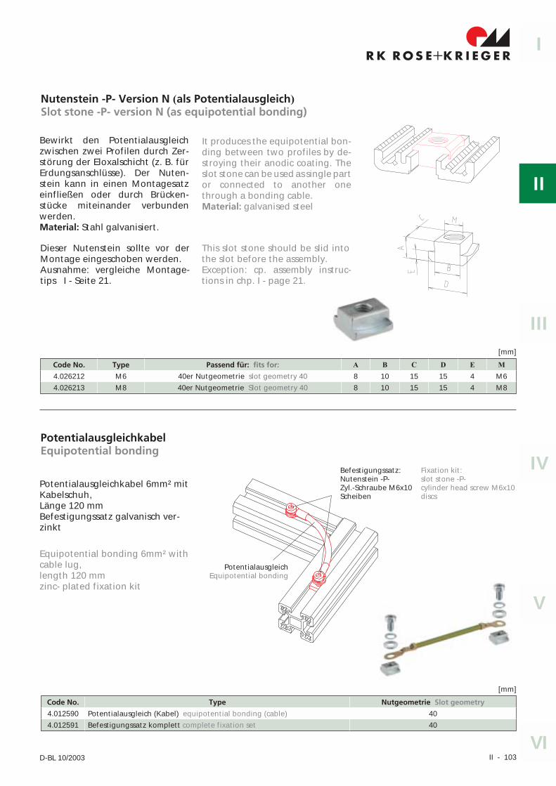
Nutenstein -P- Version N (als Potentialausgleich)
Slot stone -P- version N (as equipotential bonding)
Bewirkt den Potentialausgleichzwischen zwei Profilen durch Zer-störung der Eloxalschicht (z. B. fürErdungsanschlüsse). Der Nuten-stein kann in einen Montagesatzeinfließen oder durch Brücken-stücke miteinander verbundenwerden.Material: Stahl galvanisiert.
Code No. Type Passend für: fits for: A B C D E M
4.026212 M6 40er Nutgeometrie slot geometry 40 8 10 15 15 4 M6
4.026213 M8 40er Nutgeometrie Slot geometry 40 8 10 15 15 4 M8
[mm]
Dieser Nutenstein sollte vor derMontage eingeschoben werden.Ausnahme: vergleiche Montage-tips I - Seite 21.
It produces the equipotential bon-ding between two profiles by de-stroying their anodic coating. Theslot stone can be used as single partor connected to another onethrough a bonding cable.Material: galvanised steel
This slot stone should be slid intothe slot before the assembly.Exception: cp. assembly instruc-tions in chp. I - page 21.
PotentialausgleichkabelEquipotential bonding
Potentialausgleichkabel 6mm² mitKabelschuh,Länge 120 mmBefestigungssatz galvanisch ver-zinkt
Code No. Type Nutgeometrie Slot geometry
4.012590 Potentialausgleich (Kabel) equipotential bonding (cable) 40
4.012591 Befestigungssatz komplett complete fixation set 40
[mm]
PotentialausgleichEquipotential bonding
Befestigungssatz:Nutenstein -P-Zyl.-Schraube M6x10Scheiben
Equipotential bonding 6mm² withcable lug,length 120 mmzinc- plated fixation kit
Fixation kit:slot stone -P-cylinder head screw M6x10discs
II - 104 RK Rose+Krieger GmbH & Co. KG � Postfach 15 64 � D-32375 Minden
Nutensteine, Schrauben und ZubehörSlot stones, screws and accessories
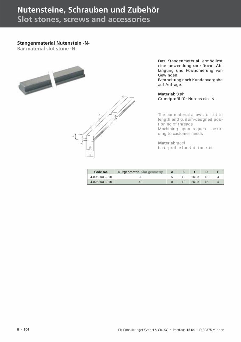
Stangenmaterial Nutenstein -N-Bar material slot stone -N-
Das Stangenmaterial ermöglichteine anwendungsspezifische Ab-längung und Positionierung vonGewinden.Bearbeitung nach Kundenvorgabeauf Anfrage.
Material: StahlGrundprofil für Nutenstein -N-
Code No. Nutgeometrie Slot geometry A B C D E
4.006200 3010 30 5 10 3010 13 3
4.026200 3010 40 8 10 3010 15 4
The bar material allows for cut tolength and custom-designed posi-tioning of threads.Machining upon request accor-ding to customer needs.
Material: steelbasic profile for slot stone -N-
II - 105
I
II
IV
III
V
VID-BL 10/2003
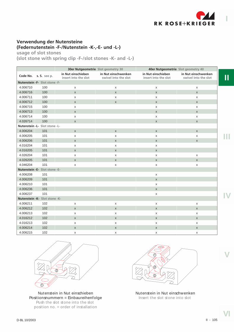
Verwendung der Nutensteine(Federnutenstein -F-/Nutenstein -K-,-E- und -L-)usage of slot stones(slot stone with spring clip -F-/slot stones -K- and -L-)
30er Nutgeometrie Slot geometry 30 40er Nutgeometrie Slot geometry 40
Code No. s. S. see p. in Nut einschiebeninsert into the slot
in Nut einschwenkenswivel into the slot
in Nut einschiebeninsert into the slot
in Nut einschwenkenswivel into the slot
Nutenstein -F- Slot stone -F-
4.006710 100 x x x x
4.006716 100 x x x x
4.006711 100 x x x x
4.006712 100 x x x x
4.006715 100 x x x
4.006713 100 x x x
4.006714 100 x x x
4.026714 100 x x x
Nutenstein -L- Slot stone -L-
4.006204 101 x x x x
4.006205 101 x x x x
4.006206 101 x x x x
4.016204 101 x x x
4.016205 101 x x x
4.026204 101 x x x x
4.026205 101 x x x x
4.046204 101 x x x x
Nutenstein -E- Slot stone -E-
4.006208 101 x
4.006209 101 x
4.006210 101 x
4.006236 101 x
4.006237 101 x
Nutenstein -K- Slot stone -K-
4.006211 102 x x x x
4.006212 102 x x x x
4.006213 102 x x x x
4.016212 102 x x x x
4.016213 102 x x x x
4.006214 102 x x x x
4.006215 102 x x x x
Nutenstein in Nut einschiebenPositionsnummern = Einbaureihenfolge
Push the slot stone into the slotposition no. = order of installation
Nutenstein in Nut einschwenkenInsert the slot stone into slot
II - 106 RK Rose+Krieger GmbH & Co. KG � Postfach 15 64 � D-32375 Minden
Nutensteine, Schrauben und ZubehörSlot stones, screws and accessories
150 N
Ø14,5
2,7
5ti
efd
eep
Ø8,5
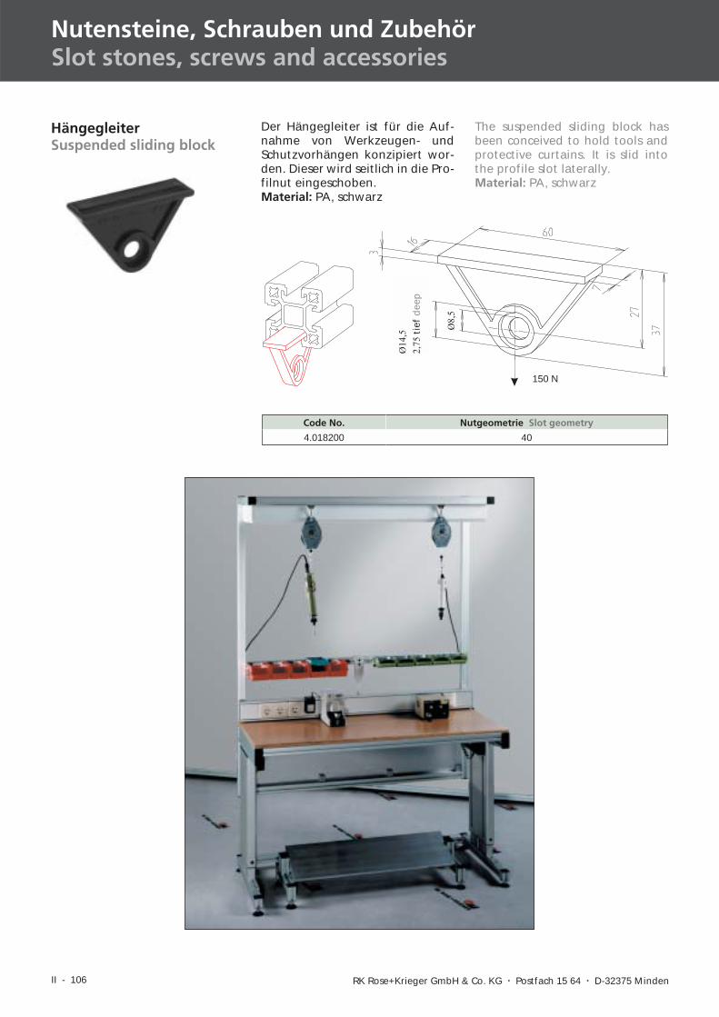
Code No. Nutgeometrie Slot geometry
4.018200 40
HängegleiterSuspended sliding block
Der Hängegleiter ist für die Auf-nahme von Werkzeugen- undSchutzvorhängen konzipiert wor-den. Dieser wird seitlich in die Pro-filnut eingeschoben.Material: PA, schwarz
The suspended sliding block hasbeen conceived to hold tools andprotective curtains. It is slid intothe profile slot laterally.Material: PA, schwarz
II - 107
I
II
IV
III
V
VID-BL 10/2003
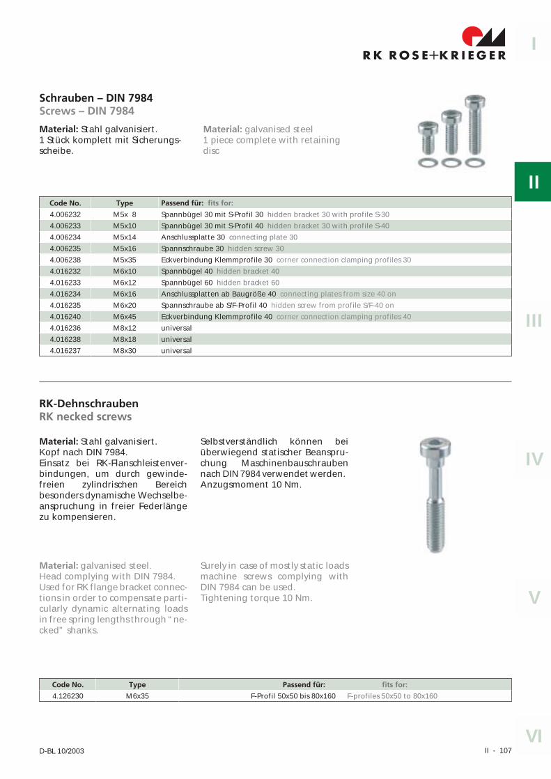
Schrauben – DIN 7984Screws – DIN 7984
Material: Stahl galvanisiert.1 Stück komplett mit Sicherungs-scheibe.
Code No. Type Passend für: fits for:
4.006232 M5x 8 Spannbügel 30 mit S-Profil 30 hidden bracket 30 with profile S-30
4.006233 M5x10 Spannbügel 30 mit S-Profil 40 hidden bracket 30 with profile S-40
4.006234 M5x14 Anschlussplatte 30 connecting plate 30
4.006235 M5x16 Spannschraube 30 hidden screw 30
4.006238 M5x35 Eckverbindung Klemmprofile 30 corner connection clamping profiles 30
4.016232 M6x10 Spannbügel 40 hidden bracket 40
4.016233 M6x12 Spannbügel 60 hidden bracket 60
4.016234 M6x16 Anschlussplatten ab Baugröße 40 connecting plates from size 40 on
4.016235 M6x20 Spannschraube ab S/F-Profil 40 hidden screw from profile S/F-40 on
4.016240 M6x45 Eckverbindung Klemmprofile 40 corner connection clamping profiles 40
4.016236 M8x12 universal
4.016238 M8x18 universal
4.016237 M8x30 universal
RK-DehnschraubenRK necked screws
Material: Stahl galvanisiert.Kopf nach DIN 7984.Einsatz bei RK-Flanschleistenver-bindungen, um durch gewinde-freien zylindrischen Bereichbesonders dynamische Wechselbe-anspruchung in freier Federlängezu kompensieren.
Selbstverständlich können beiüberwiegend statischer Beanspru-chung Maschinenbauschraubennach DIN 7984 verwendet werden.Anzugsmoment 10 Nm.
Code No. Type Passend für: fits for:
4.126230 M6x35 F-Profil 50x50 bis 80x160 F-profiles 50x50 to 80x160
Material: galvanised steel1 piece complete with retainingdisc
Material: galvanised steel.Head complying with DIN 7984.Used for RK flange bracket connec-tions in order to compensate parti-cularly dynamic alternating loadsin free spring lengths through “ne-cked” shanks.
Surely in case of mostly static loadsmachine screws complying withDIN 7984 can be used.Tightening torque 10 Nm.
II - 108 RK Rose+Krieger GmbH & Co. KG � Postfach 15 64 � D-32375 Minden
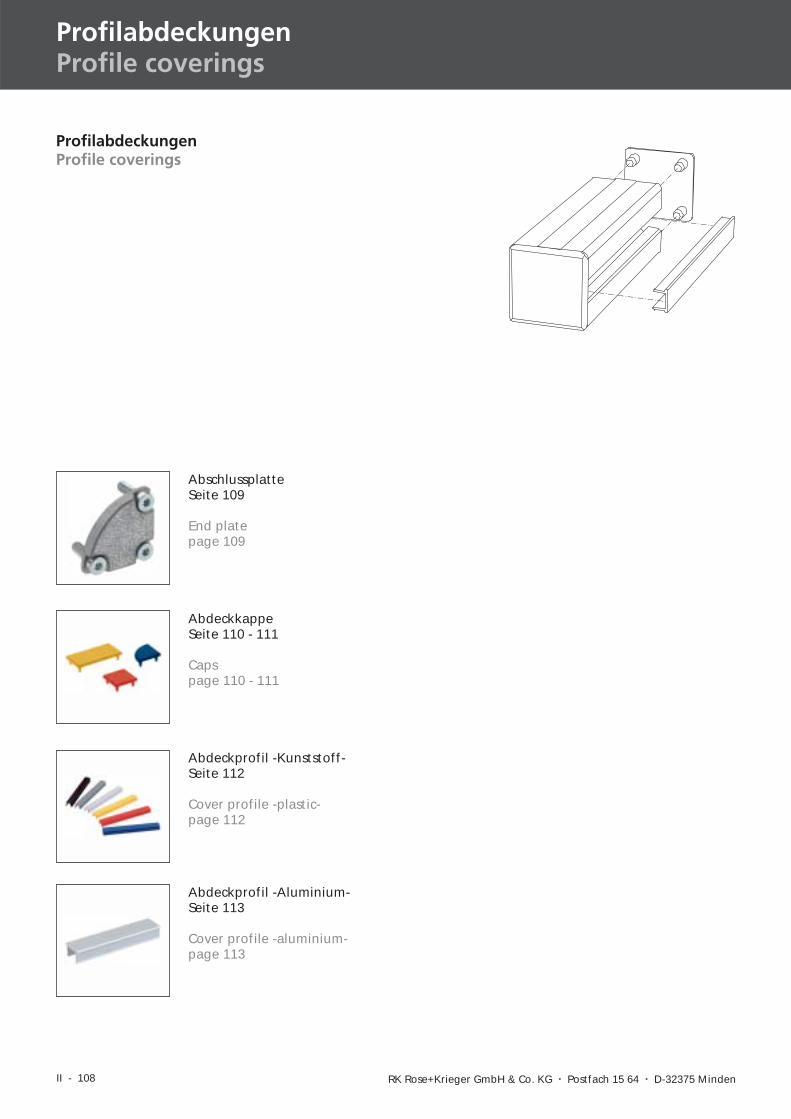
ProfilabdeckungenProfile coverings
ProfilabdeckungenProfile coverings
AbschlussplatteSeite 109
End platepage 109
AbdeckkappeSeite 110 - 111
Capspage 110 - 111
Abdeckprofil -Kunststoff-Seite 112
Cover profile -plastic-page 112
Abdeckprofil -Aluminium-Seite 113
Cover profile -aluminium-page 113
-
II - 109
I
II
IV
III
V
VID-BL 03/2004
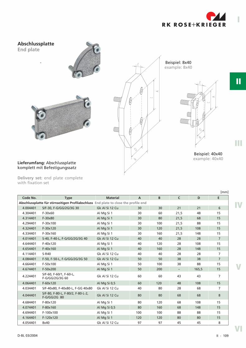
AbschlussplatteEnd plate
Beispiel: 8x40example: 8x40
Beispiel: 40x40example: 40x40
Lieferumfang: Abschlussplattekomplett mit Befestigungssatz
Delivery set: end plate completewith fixation set
Code No. Type Material A B C D E
Abschlussplatte für stirnseitigen Profilabschluss End plate to close the profile end
4.004401 S/F-30, F-G/GG/2G/3G 30 Gk Al Si 12 Cu 30 30 21 21 6
4.304401 F-30x60 Al Mg Si 1 30 60 21,5 48 15
4.314401 F-30x80 Al Mg Si 1 30 80 21,5 68 15
4.294401 F-30x100 Al Mg Si 1 30 100 21,5 88 15
4.324401 F-30x120 Al Mg Si 1 30 120 21,5 108 15
4.334401 F-30x160 Al Mg Si 1 30 160 21,5 148 15
4.014401 S-40, F-40-L, F-G/GG/2G/3G 40 Gk Al Si 12 Cu 40 40 28 28 7
4.644401 F-40x120 Al Mg Si 1 40 120 28 108 15
4.654401 F-40x160 Al Mg Si 1 40 160 28 148 15
4.114401 S-R40 Gk Al Si 12 Cu 40 40 28 28 7
4.084401 F-50, F-50-L, F-G/GG/2G/3G 50 Gk Al Si 12 Cu 50 50 38 38 7
4.664401 F-50x100 Al Mg Si 1 50 100 38 88 15
4.674401 F-50x200 Al Mg Si 1 50 200 – 165,5 15
4.224401 S/F-60, F-60/1, F-60-L,F-G/GG/2G/3G 60 Gk Al Si 12 Cu 60 60 43 43 7
4.064401 F-60x120 Al Mg Si 0,5 60 120 48 108 15
4.034401 S/F-40x80, F-40x80-L, F-GG 40x80 Gk Al Si 12 Cu 40 80 28 68 7
4.044401 S/F-80, F-80-L, F-80/2, F-80-L-2,F-G/GG/2G 80 Gk Al Si 12 Cu 80 80 68 68 8
4.684401 F-80x120 Al Mg Si 1 80 120 68 108 15
4.074401 F-80x160 Al Mg Si 0,5 80 160 68 148 15
4.694401 F-100x100 Al Mg Si 1 100 100 88 88 15
4.164401 F-120x120 Al Mg Si 1 120 120 80 80 15
4.054401 8x40 Gk Al Si 12 Cu 97 97 45 45 8
[mm]
II - 110 RK Rose+Krieger GmbH � Postfach 15 64 � D-32375 Minden
ProfilabdeckungenProfile coverings
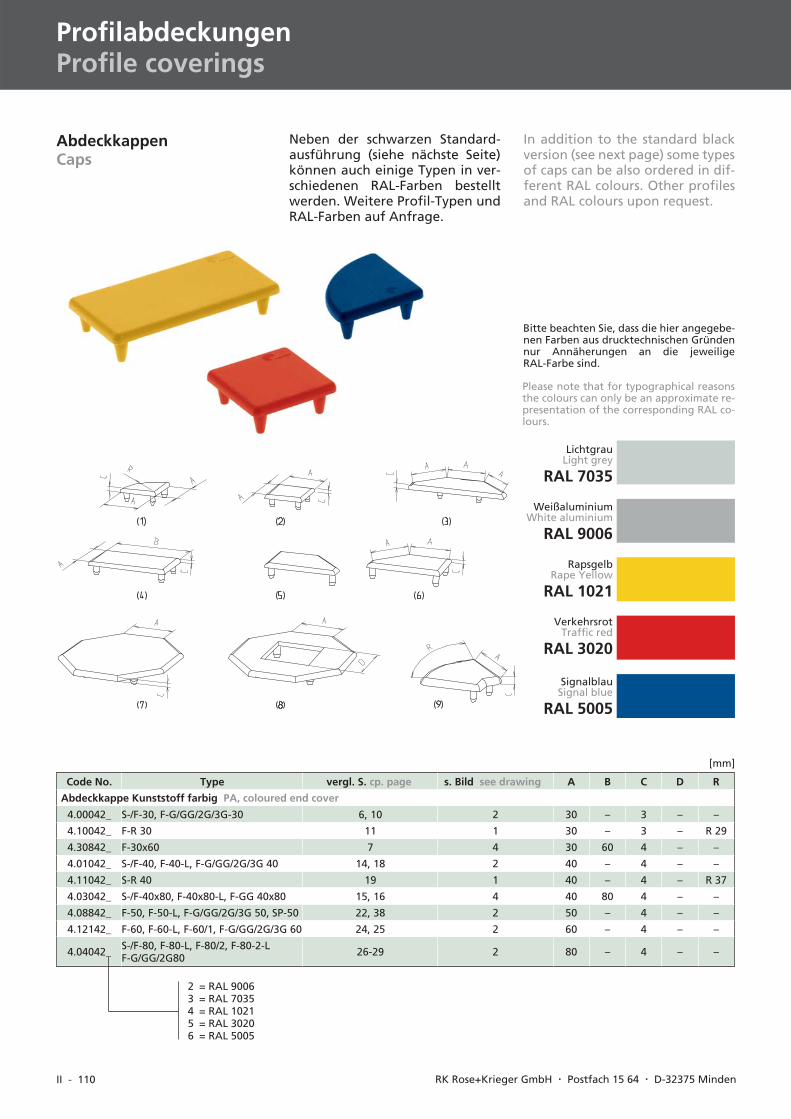
AbdeckkappenCaps
Code No. Type vergl. S. cp. page s. Bild see drawing A B C D R
Abdeckkappe Kunststoff farbig PA, coloured end cover
4.00042_ S-/F-30, F-G/GG/2G/3G-30 6, 10 2 30 – 3 – –
4.10042_ F-R 30 11 1 30 – 3 – R 29
4.30842_ F-30x60 7 4 30 60 4 – –
4.01042_ S-/F-40, F-40-L, F-G/GG/2G/3G 40 14, 18 2 40 – 4 – –
4.11042_ S-R 40 19 1 40 – 4 – R 37
4.03042_ S-/F-40x80, F-40x80-L, F-GG 40x80 15, 16 4 40 80 4 – –
4.08842_ F-50, F-50-L, F-G/GG/2G/3G 50, SP-50 22, 38 2 50 – 4 – –
4.12142_ F-60, F-60-L, F-60/1, F-G/GG/2G/3G 60 24, 25 2 60 – 4 – –
4.04042_ S-/F-80, F-80-L, F-80/2, F-80-2-LF-G/GG/2G80 26-29 2 80 – 4 – –
[mm]
2 = RAL 90063 = RAL 70354 = RAL 10215 = RAL 30206 = RAL 5005
LichtgrauLight grey
RAL 7035
WeißaluminiumWhite aluminium
RAL 9006
RapsgelbRape Yellow
RAL 1021
SignalblauSignal blue
RAL 5005
VerkehrsrotTraffic red
RAL 3020
Neben der schwarzen Standard-ausführung (siehe nächste Seite)können auch einige Typen in ver-schiedenen RAL-Farben bestelltwerden. Weitere Profil-Typen undRAL-Farben auf Anfrage.
In addition to the standard blackversion (see next page) some typesof caps can be also ordered in dif-ferent RAL colours. Other profilesand RAL colours upon request.
Bitte beachten Sie, dass die hier angegebe-nen Farben aus drucktechnischen Gründennur Annäherungen an die jeweiligeRAL-Farbe sind.
Please note that for typographical reasonsthe colours can only be an approximate re-presentation of the corresponding RAL co-lours.
II - 111
I
II
IV
III
V
VID-BL 03/2004
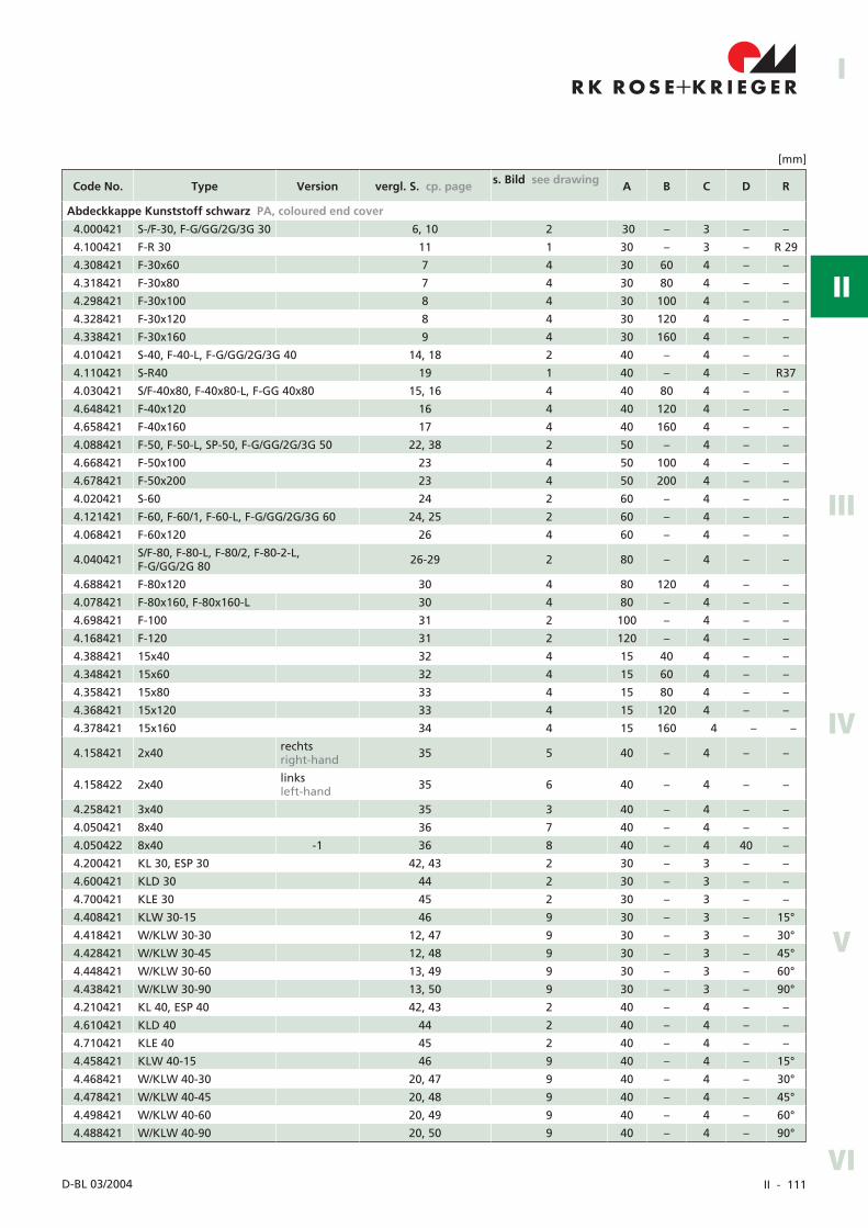
Code No. Type Version vergl. S. cp. page s. Bild see drawing A B C D R
Abdeckkappe Kunststoff schwarz PA, coloured end cover
4.000421 S-/F-30, F-G/GG/2G/3G 30 6, 10 2 30 – 3 – –
4.100421 F-R 30 11 1 30 – 3 – R 29
4.308421 F-30x60 7 4 30 60 4 – –
4.318421 F-30x80 7 4 30 80 4 – –
4.298421 F-30x100 8 4 30 100 4 – –
4.328421 F-30x120 8 4 30 120 4 – –
4.338421 F-30x160 9 4 30 160 4 – –
4.010421 S-40, F-40-L, F-G/GG/2G/3G 40 14, 18 2 40 – 4 – –
4.110421 S-R40 19 1 40 – 4 – R37
4.030421 S/F-40x80, F-40x80-L, F-GG 40x80 15, 16 4 40 80 4 – –
4.648421 F-40x120 16 4 40 120 4 – –
4.658421 F-40x160 17 4 40 160 4 – –
4.088421 F-50, F-50-L, SP-50, F-G/GG/2G/3G 50 22, 38 2 50 – 4 – –
4.668421 F-50x100 23 4 50 100 4 – –
4.678421 F-50x200 23 4 50 200 4 – –
4.020421 S-60 24 2 60 – 4 – –
4.121421 F-60, F-60/1, F-60-L, F-G/GG/2G/3G 60 24, 25 2 60 – 4 – –
4.068421 F-60x120 26 4 60 – 4 – –
4.040421 S/F-80, F-80-L, F-80/2, F-80-2-L,F-G/GG/2G 80 26-29 2 80 – 4 – –
4.688421 F-80x120 30 4 80 120 4 – –
4.078421 F-80x160, F-80x160-L 30 4 80 – 4 – –
4.698421 F-100 31 2 100 – 4 – –
4.168421 F-120 31 2 120 – 4 – –
4.388421 15x40 32 4 15 40 4 – –
4.348421 15x60 32 4 15 60 4 – –
4.358421 15x80 33 4 15 80 4 – –
4.368421 15x120 33 4 15 120 4 – –
4.378421 15x160 34 4 15 160 4 – –
4.158421 2x40 rechtsright-hand 35 5 40 – 4 – –
4.158422 2x40 linksleft-hand 35 6 40 – 4 – –
4.258421 3x40 35 3 40 – 4 – –
4.050421 8x40 36 7 40 – 4 – –
4.050422 8x40 -1 36 8 40 – 4 40 –
4.200421 KL 30, ESP 30 42, 43 2 30 – 3 – –
4.600421 KLD 30 44 2 30 – 3 – –
4.700421 KLE 30 45 2 30 – 3 – –
4.408421 KLW 30-15 46 9 30 – 3 – 15°
4.418421 W/KLW 30-30 12, 47 9 30 – 3 – 30°
4.428421 W/KLW 30-45 12, 48 9 30 – 3 – 45°
4.448421 W/KLW 30-60 13, 49 9 30 – 3 – 60°
4.438421 W/KLW 30-90 13, 50 9 30 – 3 – 90°
4.210421 KL 40, ESP 40 42, 43 2 40 – 4 – –
4.610421 KLD 40 44 2 40 – 4 – –
4.710421 KLE 40 45 2 40 – 4 – –
4.458421 KLW 40-15 46 9 40 – 4 – 15°
4.468421 W/KLW 40-30 20, 47 9 40 – 4 – 30°
4.478421 W/KLW 40-45 20, 48 9 40 – 4 – 45°
4.498421 W/KLW 40-60 20, 49 9 40 – 4 – 60°
4.488421 W/KLW 40-90 20, 50 9 40 – 4 – 90°
[mm]
II - 112 RK Rose+Krieger GmbH � Postfach 15 64 � D-32375 Minden
ProfilabdeckungenProfile coverings
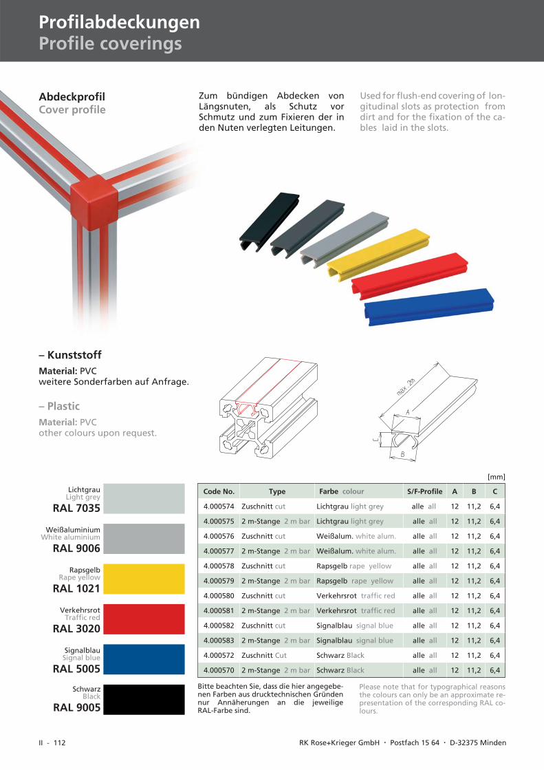
AbdeckprofilCover profile
– KunststoffMaterial: PVCweitere Sonderfarben auf Anfrage.
Bitte beachten Sie, dass die hier angegebe-nen Farben aus drucktechnischen Gründennur Annäherungen an die jeweiligeRAL-Farbe sind.
Code No. Type Farbe colour S/F-Profile A B C
4.000574 Zuschnitt cut Lichtgrau light grey alle all 12 11,2 6,4
4.000575 2 m-Stange 2 m bar Lichtgrau light grey alle all 12 11,2 6,4
4.000576 Zuschnitt cut Weißalum. white alum. alle all 12 11,2 6,4
4.000577 2 m-Stange 2 m bar Weißalum. white alum. alle all 12 11,2 6,4
4.000578 Zuschnitt cut Rapsgelb rape yellow alle all 12 11,2 6,4
4.000579 2 m-Stange 2 m bar Rapsgelb rape yellow alle all 12 11,2 6,4
4.000580 Zuschnitt cut Verkehrsrot traffic red alle all 12 11,2 6,4
4.000581 2 m-Stange 2 m bar Verkehrsrot traffic red alle all 12 11,2 6,4
4.000582 Zuschnitt cut Signalblau signal blue alle all 12 11,2 6,4
4.000583 2 m-Stange 2 m bar Signalblau signal blue alle all 12 11,2 6,4
4.000572 Zuschnitt Cut Schwarz Black alle all 12 11,2 6,4
4.000570 2 m-Stange 2 m bar Schwarz Black alle all 12 11,2 6,4
[mm]
Please note that for typographical reasonsthe colours can only be an approximate re-presentation of the corresponding RAL co-lours.
– PlasticMaterial: PVCother colours upon request.
Zum bündigen Abdecken vonLängsnuten, als Schutz vorSchmutz und zum Fixieren der inden Nuten verlegten Leitungen.
Used for flush-end covering of lon-gitudinal slots as protection fromdirt and for the fixation of the ca-bles laid in the slots.
SchwarzBlack
RAL 9005
LichtgrauLight grey
RAL 7035
WeißaluminiumWhite aluminium
RAL 9006
RapsgelbRape yellow
RAL 1021
VerkehrsrotTraffic red
RAL 3020
SignalblauSignal blue
RAL 5005
II - 113
I
II
IV
III
V
VID-BL 10/2003
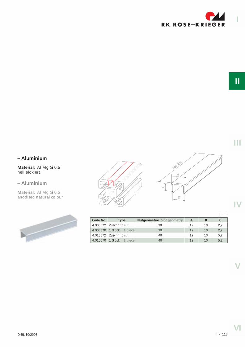
– Aluminium
Material: Al Mg Si 0,5hell eloxiert.
Code No. Type Nutgeometrie Slot geometry A B C
4.005572 Zuschnitt cut 30 12 10 2,7
4.005570 1 Stück 1 piece 30 12 10 2,7
4.015572 Zuschnitt cut 40 12 10 5,2
4.015570 1 Stück 1 piece 40 12 10 5,2
[mm]
– Aluminium
Material: Al Mg Si 0.5anodised natural colour
II - 114 RK Rose+Krieger GmbH & Co. KG � Postfach 15 64 � D-32375 Minden
Flächenelemente und ZubehörSurface Elements and Accessories
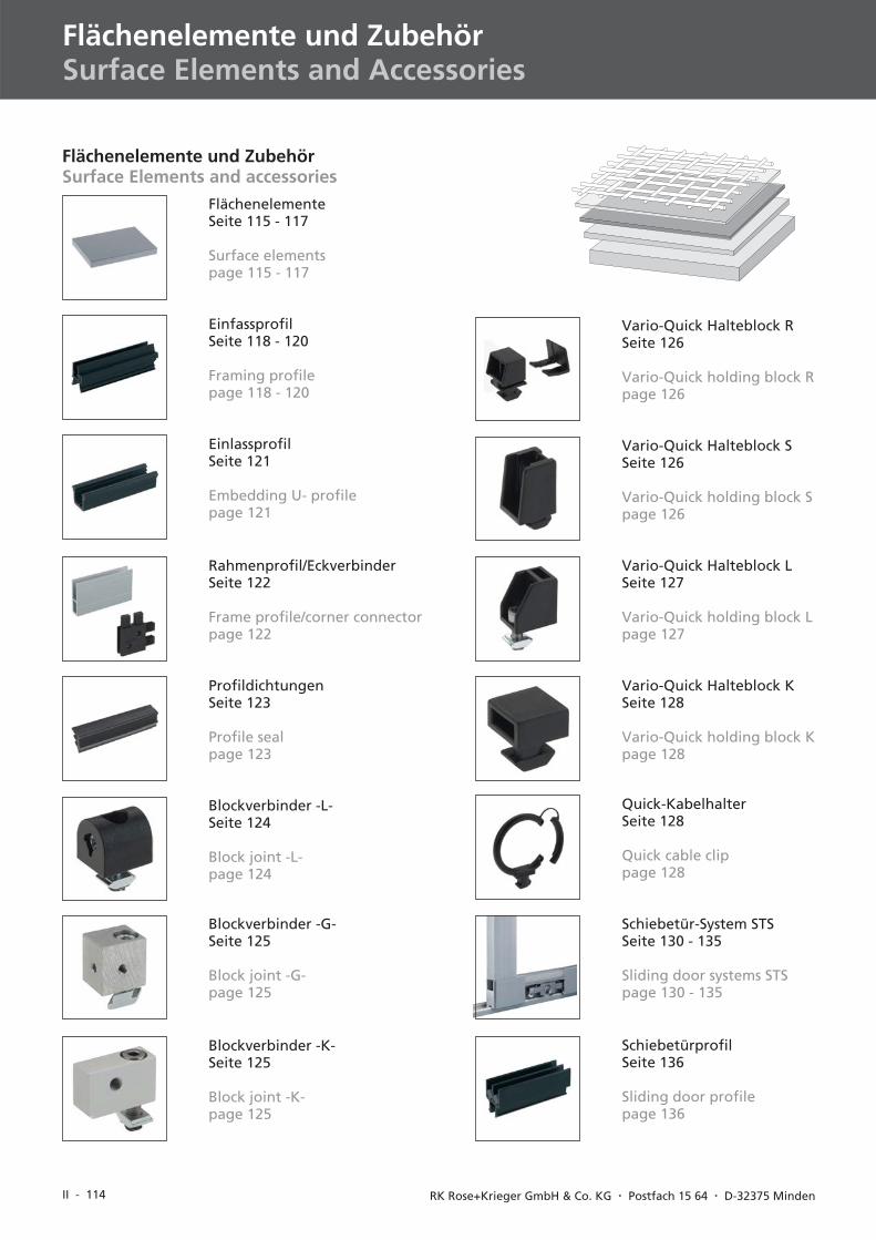
Flächenelemente und ZubehörSurface Elements and accessories
FlächenelementeSeite 115 - 117
Surface elementspage 115 - 117
EinfassprofilSeite 118 - 120
Framing profilepage 118 - 120
EinlassprofilSeite 121
Embedding U- profilepage 121
Blockverbinder -L-Seite 124
Block joint -L-page 124
Blockverbinder -G-Seite 125
Block joint -G-page 125
Blockverbinder -K-Seite 125
Block joint -K-page 125
Vario-Quick Halteblock RSeite 126
Vario-Quick holding block Rpage 126
ProfildichtungenSeite 123
Profile sealpage 123
Rahmenprofil/EckverbinderSeite 122
Frame profile/corner connectorpage 122
Vario-Quick Halteblock SSeite 126
Vario-Quick holding block Spage 126
Vario-Quick Halteblock LSeite 127
Vario-Quick holding block Lpage 127
Vario-Quick Halteblock KSeite 128
Vario-Quick holding block Kpage 128
Quick-KabelhalterSeite 128
Quick cable clippage 128
Schiebetür-System STSSeite 130 - 135
Sliding door systems STSpage 130 - 135
SchiebetürprofilSeite 136
Sliding door profilepage 136
II - 115
I
II
IV
III
V
VID-BL 10/2003
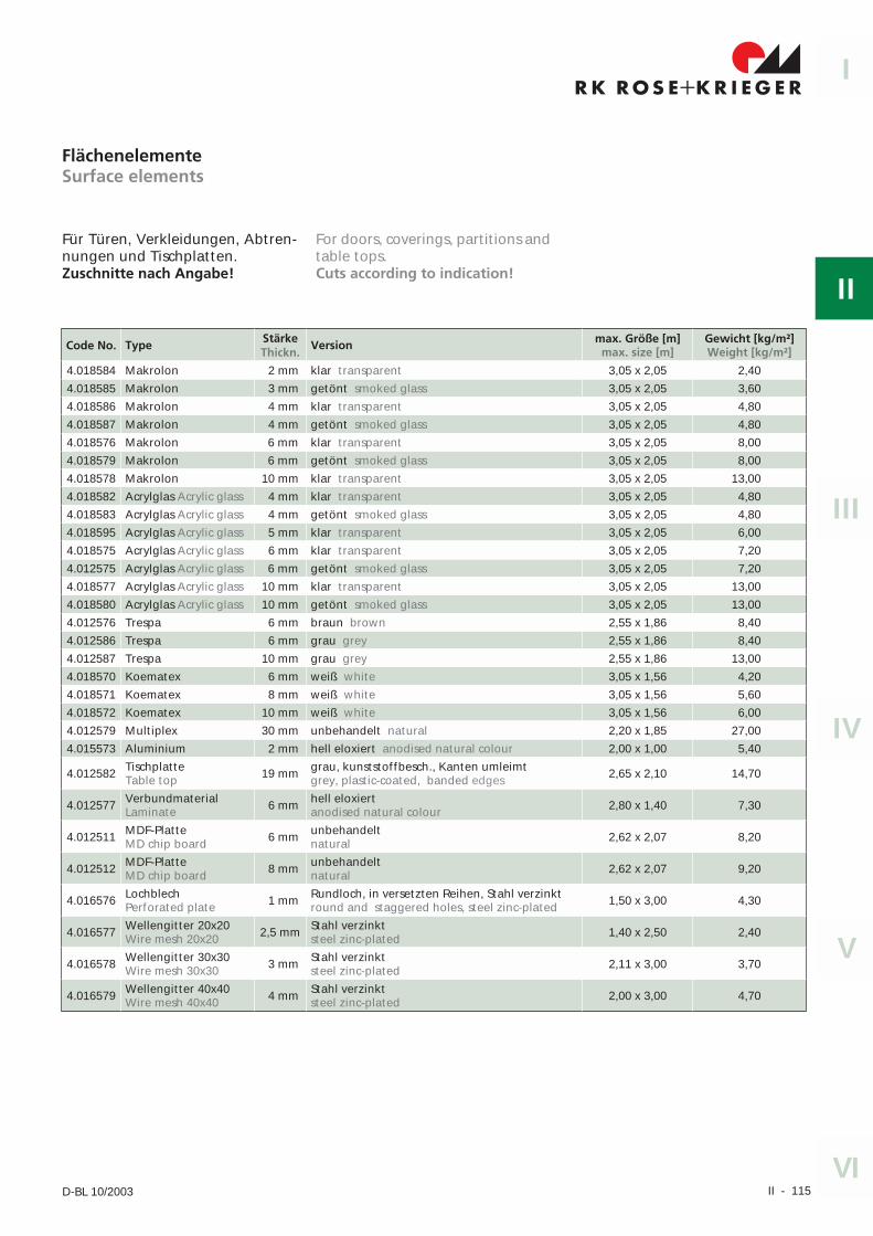
Für Türen, Verkleidungen, Abtren-nungen und Tischplatten.Zuschnitte nach Angabe!
Code No. Type StärkeThickn.
Version max. Größe [m]max. size [m]
Gewicht [kg/m²]Weight [kg/m²]
4.018584 Makrolon 2 mm klar transparent 3,05 x 2,05 2,40
4.018585 Makrolon 3 mm getönt smoked glass 3,05 x 2,05 3,60
4.018586 Makrolon 4 mm klar transparent 3,05 x 2,05 4,80
4.018587 Makrolon 4 mm getönt smoked glass 3,05 x 2,05 4,80
4.018576 Makrolon 6 mm klar transparent 3,05 x 2,05 8,00
4.018579 Makrolon 6 mm getönt smoked glass 3,05 x 2,05 8,00
4.018578 Makrolon 10 mm klar transparent 3,05 x 2,05 13,00
4.018582 Acrylglas Acrylic glass 4 mm klar transparent 3,05 x 2,05 4,80
4.018583 Acrylglas Acrylic glass 4 mm getönt smoked glass 3,05 x 2,05 4,80
4.018595 Acrylglas Acrylic glass 5 mm klar transparent 3,05 x 2,05 6,00
4.018575 Acrylglas Acrylic glass 6 mm klar transparent 3,05 x 2,05 7,20
4.012575 Acrylglas Acrylic glass 6 mm getönt smoked glass 3,05 x 2,05 7,20
4.018577 Acrylglas Acrylic glass 10 mm klar transparent 3,05 x 2,05 13,00
4.018580 Acrylglas Acrylic glass 10 mm getönt smoked glass 3,05 x 2,05 13,00
4.012576 Trespa 6 mm braun brown 2,55 x 1,86 8,40
4.012586 Trespa 6 mm grau grey 2,55 x 1,86 8,40
4.012587 Trespa 10 mm grau grey 2,55 x 1,86 13,00
4.018570 Koematex 6 mm weiß white 3,05 x 1,56 4,20
4.018571 Koematex 8 mm weiß white 3,05 x 1,56 5,60
4.018572 Koematex 10 mm weiß white 3,05 x 1,56 6,00
4.012579 Multiplex 30 mm unbehandelt natural 2,20 x 1,85 27,00
4.015573 Aluminium 2 mm hell eloxiert anodised natural colour 2,00 x 1,00 5,40
4.012582 TischplatteTable top 19 mm grau, kunststoffbesch., Kanten umleimt
grey, plastic-coated, banded edges 2,65 x 2,10 14,70
4.012577 VerbundmaterialLaminate 6 mm hell eloxiert
anodised natural colour 2,80 x 1,40 7,30
4.012511 MDF-PlatteMD chip board 6 mm unbehandelt
natural 2,62 x 2,07 8,20
4.012512 MDF-PlatteMD chip board 8 mm unbehandelt
natural 2,62 x 2,07 9,20
4.016576 LochblechPerforated plate 1 mm Rundloch, in versetzten Reihen, Stahl verzinkt
round and staggered holes, steel zinc-plated 1,50 x 3,00 4,30
4.016577 Wellengitter 20x20Wire mesh 20x20 2,5 mm Stahl verzinkt
steel zinc-plated 1,40 x 2,50 2,40
4.016578 Wellengitter 30x30Wire mesh 30x30 3 mm Stahl verzinkt
steel zinc-plated 2,11 x 3,00 3,70
4.016579 Wellengitter 40x40Wire mesh 40x40 4 mm Stahl verzinkt
steel zinc-plated 2,00 x 3,00 4,70
FlächenelementeSurface elements
For doors, coverings, partitions andtable tops.Cuts according to indication!
II - 116 RK Rose+Krieger GmbH & Co. KG � Postfach 15 64 � D-32375 Minden
Flächenelemente und ZubehörSurface elements and accessories
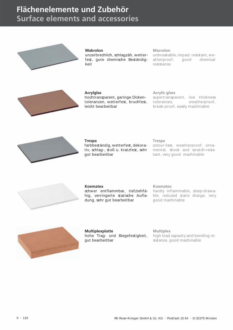
Acrylic glasssupertransparent, low thicknesstolerances, weatherproof,break-proof, easily machinable
Makrolonunzerbrechlich, schlagzäh, wetter-fest, gute chemische Beständig-keit
Koematexhardly inflammable, deep-drawa-ble, reduced static charge, verygood machinable
Multiplexhigh load capacity and bending re-sistance, good machinable
Macrolonunbreakable, impact resistant, we-atherproof, good chemicalresistance
Trespacolour-fast, weatherproof, orna-mental, shock and scratch-resis-tant, very good machinable
Acrylglashochtransparent, geringe Dicken-toleranzen, wetterfest, bruchfest,leicht bearbeitbar
Trespafarbbeständig, wetterfest, dekora-tiv, schlag-, stoß u. kratzfest, sehrgut bearbeitbar
Koematexschwer entflammbar, tiefziehfä-hig, verringerte statische Aufla-dung, sehr gut bearbeitbar
Multiplexplattehohe Trag- und Biegefestigkeit,gut bearbeitbar
II - 117
I
II
IV
III
V
VID-BL 10/2003
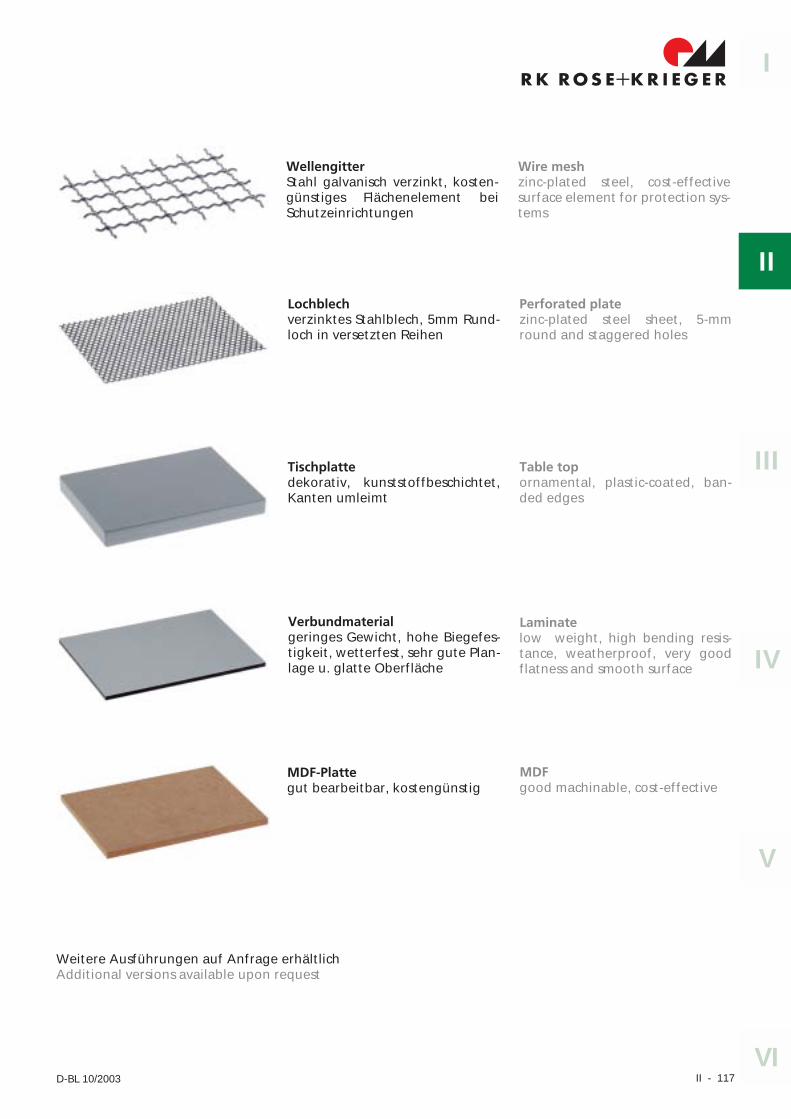
Lochblechverzinktes Stahlblech, 5mm Rund-loch in versetzten Reihen
Verbundmaterialgeringes Gewicht, hohe Biegefes-tigkeit, wetterfest, sehr gute Plan-lage u. glatte Oberfläche
MDF-Plattegut bearbeitbar, kostengünstig
Laminatelow weight, high bending resis-tance, weatherproof, very goodflatness and smooth surface
MDFgood machinable, cost-effective
WellengitterStahl galvanisch verzinkt, kosten-günstiges Flächenelement beiSchutzeinrichtungen
Wire meshzinc-plated steel, cost-effectivesurface element for protection sys-tems
Tischplattedekorativ, kunststoffbeschichtet,Kanten umleimt
Perforated platezinc-plated steel sheet, 5-mmround and staggered holes
Table topornamental, plastic-coated, ban-ded edges
Weitere Ausführungen auf Anfrage erhältlichAdditional versions available upon request
II - 118 RK Rose+Krieger GmbH & Co. KG � Postfach 15 64 � D-32375 Minden
Flächenelemente und ZubehörSurface elements and accessories
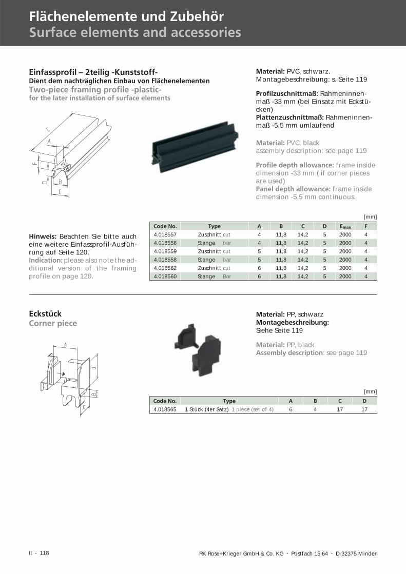
Einfassprofil – 2teilig -Kunststoff-Dient dem nachträglichen Einbau von FlächenelementenTwo-piece framing profile -plastic-for the later installation of surface elements
Material: PVC, schwarz.Montagebeschreibung: s. Seite 119
Profilzuschnittmaß: Rahmeninnen-maß -33 mm (bei Einsatz mit Eckstü-cken)Plattenzuschnittmaß: Rahmeninnen-maß -5,5 mm umlaufend
Code No. Type A B C D Emax F
4.018557 Zuschnitt cut 4 11,8 14,2 5 2000 4
4.018556 Stange bar 4 11,8 14,2 5 2000 4
4.018559 Zuschnitt cut 5 11,8 14,2 5 2000 4
4.018558 Stange bar 5 11,8 14,2 5 2000 4
4.018562 Zuschnitt cut 6 11,8 14,2 5 2000 4
4.018560 Stange Bar 6 11,8 14,2 5 2000 4
[mm]
EckstückCorner piece
Material: PP, schwarzMontagebeschreibung:Siehe Seite 119
Code No. Type A B C D
4.018565 1 Stück (4er Satz) 1 piece (set of 4) 6 4 17 17
[mm]
Material: PVC, blackassembly description: see page 119
Profile depth allowance: frame insidedimension -33 mm ( if corner piecesare used)Panel depth allowance: frame insidedimension -5,5 mm continuous.
Material: PP, blackAssembly description: see page 119
Hinweis: Beachten Sie bitte aucheine weitere Einfassprofil-Ausfüh-rung auf Seite 120.Indication: please also note the ad-ditional version of the framingprofile on page 120.
II - 119
I
II
IV
III
V
VID-BL 10/2003
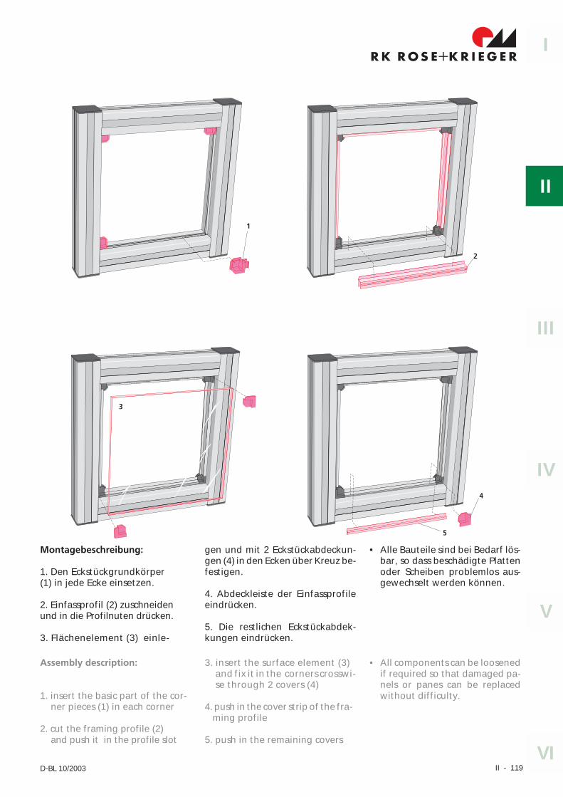
Montagebeschreibung:
1. Den Eckstückgrundkörper(1) in jede Ecke einsetzen.
2. Einfassprofil (2) zuschneidenund in die Profilnuten drücken.
3. Flächenelement (3) einle-
gen und mit 2 Eckstückabdeckun-gen (4) in den Ecken über Kreuz be-festigen.
4. Abdeckleiste der Einfassprofileeindrücken.
5. Die restlichen Eckstückabdek-kungen eindrücken.
• Alle Bauteile sind bei Bedarf lös-bar, so dass beschädigte Plattenoder Scheiben problemlos aus-gewechselt werden können.
Assembly description:
1. insert the basic part of the cor-ner pieces (1) in each corner
2. cut the framing profile (2)and push it in the profile slot
3. insert the surface element (3)and fix it in the corners crosswi-se through 2 covers (4)
4. push in the cover strip of the fra-ming profile
5. push in the remaining covers
• All components can be loosenedif required so that damaged pa-nels or panes can be replacedwithout difficulty.
II - 120 RK Rose+Krieger GmbH & Co. KG � Postfach 15 64 � D-32375 Minden
Flächenelemente und ZubehörSurface elements and accessories
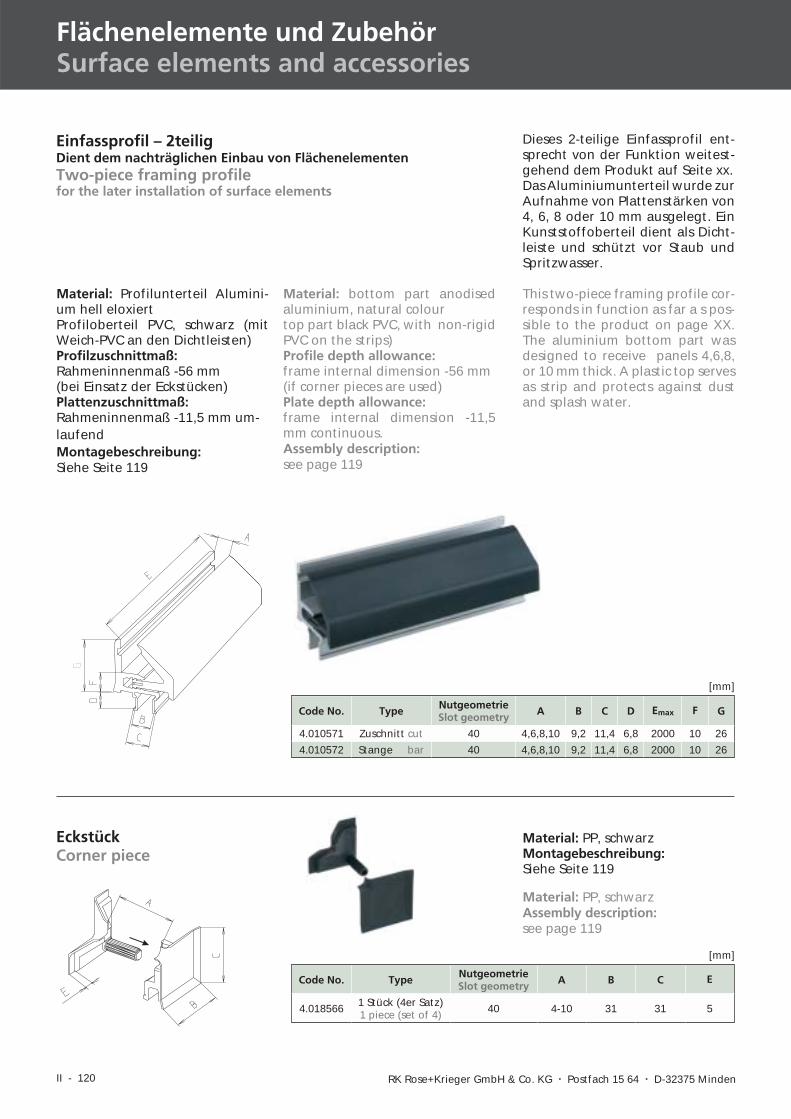
Dieses 2-teilige Einfassprofil ent-sprecht von der Funktion weitest-gehend dem Produkt auf Seite xx.Das Aluminiumunterteil wurde zurAufnahme von Plattenstärken von4, 6, 8 oder 10 mm ausgelegt. EinKunststoffoberteil dient als Dicht-leiste und schützt vor Staub undSpritzwasser.
This two-piece framing profile cor-responds in function as far a s pos-sible to the product on page XX.The aluminium bottom part wasdesigned to receive panels 4,6,8,or 10 mm thick. A plastic top servesas strip and protects against dustand splash water.
Code No. Type NutgeometrieSlot geometry A B C D Emax F G
4.010571 Zuschnitt cut 40 4,6,8,10 9,2 11,4 6,8 2000 10 26
4.010572 Stange bar 40 4,6,8,10 9,2 11,4 6,8 2000 10 26
[mm]
Einfassprofil – 2teiligDient dem nachträglichen Einbau von FlächenelementenTwo-piece framing profilefor the later installation of surface elements
Code No. Type NutgeometrieSlot geometry A B C E
4.018566 1 Stück (4er Satz)1 piece (set of 4) 40 4-10 31 31 5
[mm]
EckstückCorner piece
Material: PP, schwarzMontagebeschreibung:Siehe Seite 119
Material: Profilunterteil Alumini-um hell eloxiertProfiloberteil PVC, schwarz (mitWeich-PVC an den Dichtleisten)Profilzuschnittmaß:Rahmeninnenmaß -56 mm(bei Einsatz der Eckstücken)Plattenzuschnittmaß:Rahmeninnenmaß -11,5 mm um-laufendMontagebeschreibung:Siehe Seite 119
Material: bottom part anodisedaluminium, natural colourtop part black PVC, with non-rigidPVC on the strips)Profile depth allowance:frame internal dimension -56 mm(if corner pieces are used)Plate depth allowance:frame internal dimension -11,5mm continuous.Assembly description:see page 119
Material: PP, schwarzAssembly description:see page 119
II - 121
I
II
IV
III
V
VID-BL 10/2003
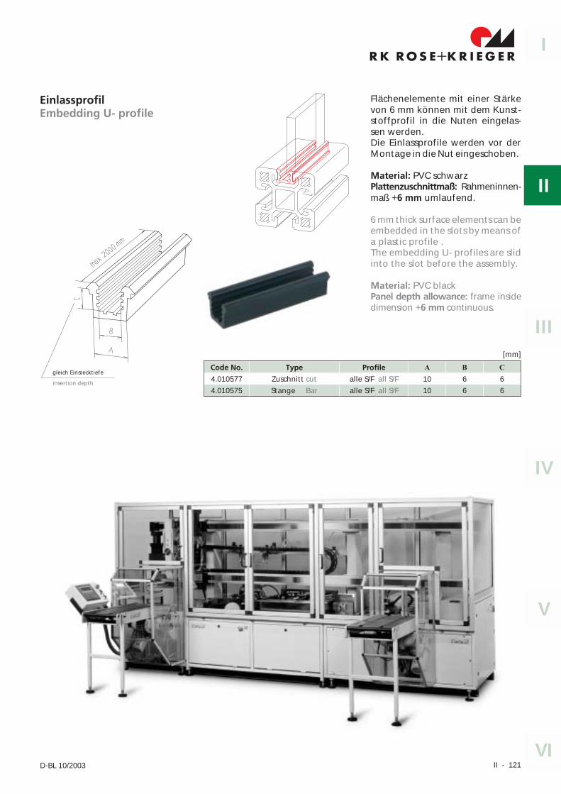
EinlassprofilEmbedding U- profile
Flächenelemente mit einer Stärkevon 6 mm können mit dem Kunst-stoffprofil in die Nuten eingelas-sen werden.Die Einlassprofile werden vor derMontage in die Nut eingeschoben.
Material: PVC schwarzPlattenzuschnittmaß: Rahmeninnen-maß +6 mm umlaufend.
6 mm thick surface elements can beembedded in the slots by means ofa plastic profile .The embedding U- profiles are slidinto the slot before the assembly.
Material: PVC blackPanel depth allowance: frame insidedimension +6 mm continuous.
Code No. Type Profile A B C
4.010577 Zuschnitt cut alle S/F all S/F 10 6 6
4.010575 Stange Bar alle S/F all S/F 10 6 6
[mm]
gleich Einstecktiefe
insertion depth
II - 122 RK Rose+Krieger GmbH & Co. KG � Postfach 15 64 � D-32375 Minden
Flächenelemente und ZubehörSurface elements and accessories
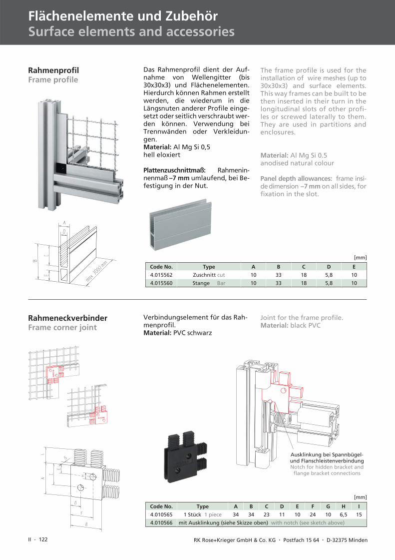
RahmenprofilFrame profile
Das Rahmenprofil dient der Auf-nahme von Wellengitter (bis30x30x3) und Flächenelementen.Hierdurch können Rahmen erstelltwerden, die wiederum in dieLängsnuten anderer Profile einge-setzt oder seitlich verschraubt wer-den können. Verwendung beiTrennwänden oder Verkleidun-gen.Material: Al Mg Si 0,5hell eloxiert
Plattenzuschnittmaß: Rahmenin-nenmaß –7 mm umlaufend, bei Be-festigung in der Nut.
Code No. Type A B C D E
4.015562 Zuschnitt cut 10 33 18 5,8 10
4.015560 Stange Bar 10 33 18 5,8 10
[mm]
RahmeneckverbinderFrame corner joint
Verbindungselement für das Rah-menprofil.Material: PVC schwarz
Code No. Type A B C D E F G H I
4.010565 1 Stück 1 piece 34 34 23 11 10 24 10 6,5 15
4.010566 mit Ausklinkung (siehe Skizze oben) with notch (see sketch above)
[mm]
Ausklinkung bei Spannbügel-und FlanschleistenverbindungNotch for hidden bracket and
flange bracket connections
The frame profile is used for theinstallation of wire meshes (up to30x30x3) and surface elements.This way frames can be built to bethen inserted in their turn in thelongitudinal slots of other profi-les or screwed laterally to them.They are used in partitions andenclosures.
Material: Al Mg Si 0.5anodised natural colour
Panel depth allowances: frame insi-dedimension –7 mm on all sides, forfixation in the slot.
Joint for the frame profile.Material: black PVC
II - 123
R K R OS E K R I EG E R+I
II
IV
III
V
VID-BL 09/2004
Code No. Abdichtungsealing
für Plattenstärkefor panel thickness
Nutgeometrieslot geometry
max. Längemax. length
4.018515 beidseitig beidseitig 6 mm 40 60 m
4.218571 einseitig one-sided für alle Klemmprofile*for all clamping profiles* 30, 40 200 m
4.018513 einseitig one-sided 4 mm 40 100 m
4.018514 einseitig one-sided 6 mm 40 200 m
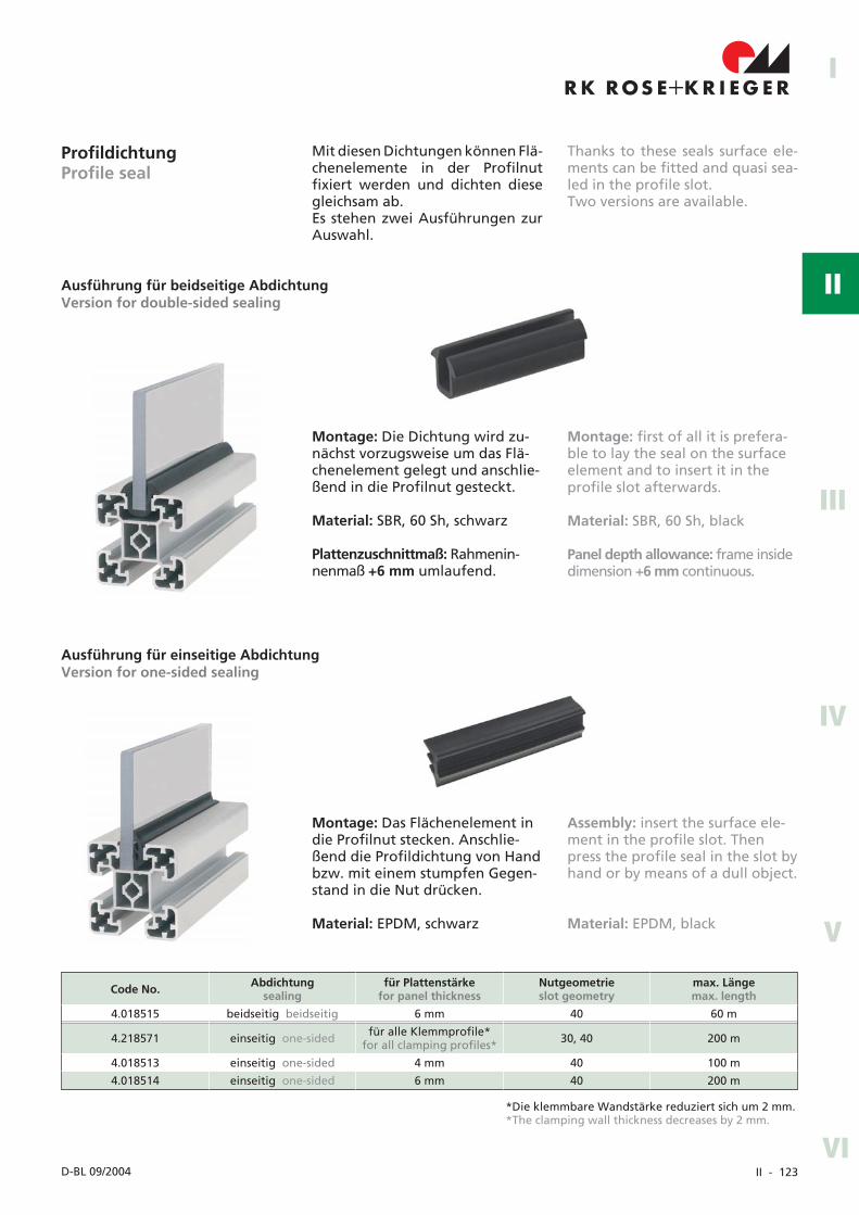
ProfildichtungProfile seal
Mit diesen Dichtungen können Flä-chenelemente in der Profilnutfixiert werden und dichten diesegleichsam ab.Es stehen zwei Ausführungen zurAuswahl.
Montage: Die Dichtung wird zu-nächst vorzugsweise um das Flä-chenelement gelegt und anschlie-ßend in die Profilnut gesteckt.
Material: SBR, 60 Sh, schwarz
Plattenzuschnittmaß: Rahmenin-nenmaß +6 mm umlaufend.
Ausführung für beidseitige AbdichtungVersion for double-sided sealing
Montage: first of all it is prefera-ble to lay the seal on the surfaceelement and to insert it in theprofile slot afterwards.
Material: SBR, 60 Sh, black
Panel depth allowance: frame insidedimension +6 mm continuous.
Ausführung für einseitige AbdichtungVersion for one-sided sealing
Assembly: insert the surface ele-ment in the profile slot. Thenpress the profile seal in the slot byhand or by means of a dull object.
Material: EPDM, black
Montage: Das Flächenelement indie Profilnut stecken. Anschlie-ßend die Profildichtung von Handbzw. mit einem stumpfen Gegen-stand in die Nut drücken.
Material: EPDM, schwarz
Thanks to these seals surface ele-ments can be fitted and quasi sea-led in the profile slot.Two versions are available.
*Die klemmbare Wandstärke reduziert sich um 2 mm.*The clamping wall thickness decreases by 2 mm.
II - 124 RK Rose+Krieger GmbH & Co. KG � Postfach 15 64 � D-32375 Minden
Flächenelemente und ZubehörSurface elements and accessories
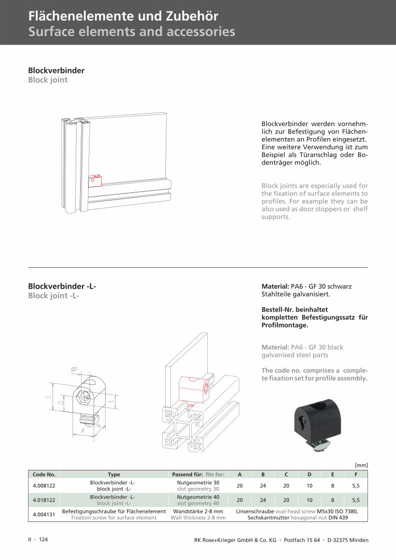
BlockverbinderBlock joint
Blockverbinder -L-Block joint -L-
Material: PA6 - GF 30 schwarzStahlteile galvanisiert.
Bestell-Nr. beinhaltetkompletten Befestigungssatz fürProfilmontage.
Code No. Type Passend für: fits for: A B C D E F
4.008122 Blockverbinder -L-block joint -L-
Nutgeometrie 30slot geometry 30 20 24 20 10 8 5,5
4.018122 Blockverbinder -L-block joint -L-
Nutgeometrie 40slot geometry 40 20 24 20 10 8 5,5
4.004131 Befestigungsschraube für FlächenelementFixation screw for surface element
Wandstärke 2-8 mmWall thickness 2-8 mm
Linsenschraube oval-head screw M5x30 ISO 7380,Sechskantmutter hexagonal nut DIN 439
[mm]
Material: PA6 - GF 30 blackgalvanised steel parts
The code no. comprises a comple-te fixation set for profile assembly.
Blockverbinder werden vornehm-lich zur Befestigung von Flächen-elementen an Profilen eingesetzt.Eine weitere Verwendung ist zumBeispiel als Türanschlag oder Bo-denträger möglich.
Block joints are especially used forthe fixation of surface elements toprofiles. For example they can bealso used as door stoppers or shelfsupports.
II - 125
I
II
IV
III
V
VID-BL 10/2003
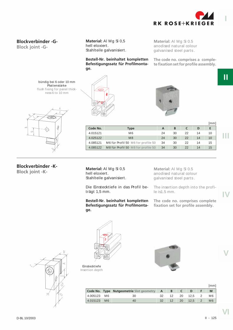
Blockverbinder -G-Block joint -G-
Material: Al Mg Si 0,5hell eloxiert.Stahlteile galvanisiert.
Bestell-Nr. beinhaltet komplettenBefestigungssatz für Profilmonta-ge.
Blockverbinder -K-Block joint -K-
Material: Al Mg Si 0,5hell eloxiert.Stahlteile galvanisiert.
Die Einstecktiefe in das Profil be-trägt 1,5 mm.
Bestell-Nr. beinhaltet komplettenBefestigungssatz für Profilmonta-ge.
Code No. Type Nutgeometrie Slot geometry A B C D F M
4.005123 M6 30 32 12 20 12,5 2 M6
4.015123 M6 40 32 12 20 12,5 2 M6
[mm]
Code No. Type A B C D E
4.015121 M6 24 30 22 14 10
4.025122 M8 24 30 22 14 10
4.085121 M6 für Profil 50 M6 for profile 50 34 30 22 14 15
4.085122 M8 für Profil 50 M8 for profile 50 34 30 22 14 15
[mm]
bündig bei 6 oder 10 mmPlattenstärke
flush fixing for panel thick-ness 6 to 10 mm
EinstecktiefeInsertion depth
Material: Al Mg Si 0.5anodised natural colourgalvanised steel parts .
The code no. comprises a comple-te fixation set for profile assembly.
Material: Al Mg Si 0.5anodised natural colourgalvanised steel parts .
The insertion depth into the profi-le is1.5 mm.
The code no. comprises completefixation set for profile assembly.
II - 126 RK Rose+Krieger GmbH & Co. KG � Postfach 15 64 � D-32375 Minden
Flächenelemente und ZubehörSurface elements and accessories
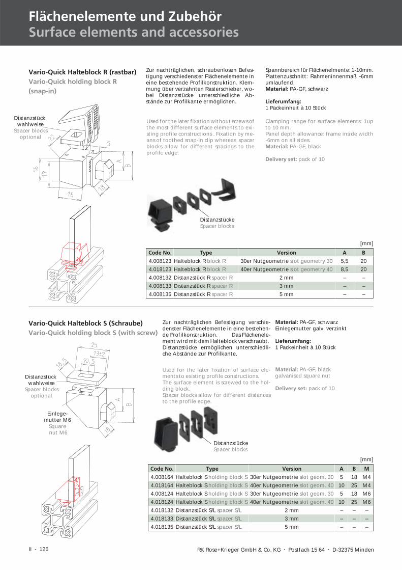
Material: PA-GF, blackgalvanised square nut
Delivery set: pack of 10
Vario-Quick Halteblock R (rastbar)Vario-Quick holding block R(snap-in)
Vario-Quick Halteblock S (Schraube)Vario-Quick holding block S (with screw)
Zur nachträglichen, schraubenlosen Befes-tigung verschiedenster Flächenelemente ineine bestehende Profilkonstruktion. Klem-mung über verzahnten Rasterschieber, wo-bei Distanzstücke unterschiedliche Ab-stände zur Profilkante ermöglichen.
Spannbereich für Flächenelmente: 1-10mm.Plattenzuschnitt: Rahmeninnenmaß -6mmumlaufend.Material: PA-GF, schwarz
Lieferumfang:1 Packeinheit à 10 Stück
Zur nachträglichen Befestigung verschie-denster Flächenelemente in eine bestehen-de Profilkonstruktion. Das Flächenele-ment wird mit dem Halteblock verschraubt.Distanzstücke ermöglichen unterschiedli-che Abstände zur Profilkante.
Material: PA-GF, schwarzEinlegemutter galv. verzinkt
Lieferumfang:1 Packeinheit à 10 Stück
Code No. Type Version A B
4.008123 Halteblock R block R 30er Nutgeometrie slot geometry 30 5,5 20
4.018123 Halteblock R block R 40er Nutgeometrie slot geometry 40 8,5 20
4.008132 Distanzstück R spacer R 2 mm – –
4.008133 Distanzstück R spacer R 3 mm – –
4.008135 Distanzstück R spacer R 5 mm – –
[mm]
Code No. Type Version A B M
4.008164 Halteblock S holding block S 30er Nutgeometrie slot geom. 30 5 18 M4
4.018164 Halteblock S holding block S 40er Nutgeometrie slot geom. 40 10 25 M4
4.008124 Halteblock S holding block S 30er Nutgeometrie slot geom. 30 5 18 M6
4.018124 Halteblock S holding block S 40er Nutgeometrie slot geom. 40 10 25 M6
4.018132 Distanzstück S/L spacer S/L 2 mm – – –
4.018133 Distanzstück S/L spacer S/L 3 mm – – –
4.018135 Distanzstück S/L spacer S/L 5 mm – – –
[mm]
Distanzstückwahlweise
Spacer blocksoptional
Einlege-mutter M6
Squarenut M6
Distanzstückwahlweise
Spacer blocksoptional
Used for the later fixation without screws ofthe most different surface elements to exi-sting profile constructions . Fixation by me-ans of toothed snap-in clip whereas spacerblocks allow for different spacings to theprofile edge.
Clamping range for surface elements: 1upto 10 mm.Panel depth allowance: frame inside width-6mm on all sides.Material: PA-GF, black
Delivery set: pack of 10
Used for the later fixation of surface ele-ments to existing profile constructions.The surface element is screwed to the hol-ding block.Spacer blocks allow for different distancesto the profile edge.
DistanzstückeSpacer blocks
DistanzstückeSpacer blocks
II - 127
I
II
IV
III
V
VID-BL 10/2003
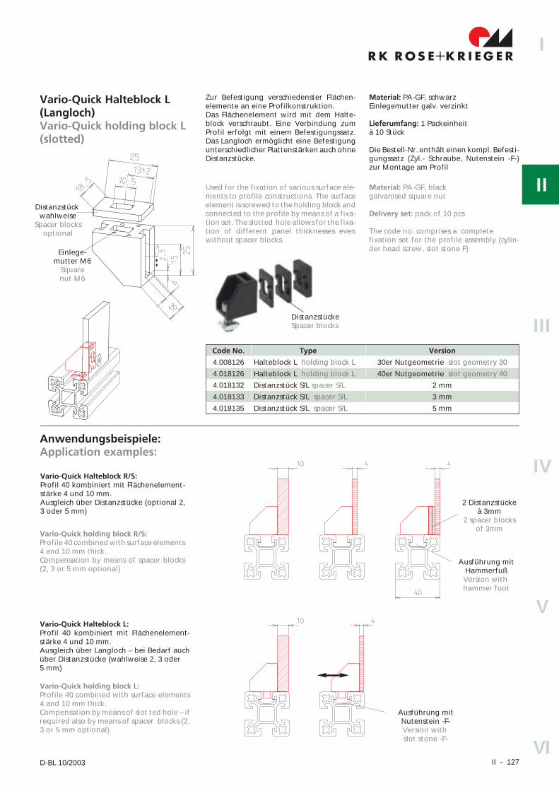
Vario-Quick Halteblock L(Langloch)Vario-Quick holding block L(slotted)
Code No. Type Version
4.008126 Halteblock L holding block L 30er Nutgeometrie slot geometry 30
4.018126 Halteblock L holding block L 40er Nutgeometrie slot geometry 40
4.018132 Distanzstück S/L spacer S/L 2 mm
4.018133 Distanzstück S/L spacer S/L 3 mm
4.018135 Distanzstück S/L spacer S/L 5 mm
Distanzstückwahlweise
Spacer blocksoptional
Einlege-mutter M6
Squarenut M6
Anwendungsbeispiele:Application examples:
2 Distanzstückeà 3mm
2 spacer blocksof 3mm
Ausführung mitHammerfußVersion withhammer foot
Ausführung mitNutenstein -F-Version withslot stone -F-
Vario-Quick Halteblock L:Profil 40 kombiniert mit Flächenelement-stärke 4 und 10 mm.Ausgleich über Langloch – bei Bedarf auchüber Distanzstücke (wahlweise 2, 3 oder5 mm)
Vario-Quick Halteblock R/S:Profil 40 kombiniert mit Flächenelement-stärke 4 und 10 mm.Ausgleich über Distanzstücke (optional 2,3 oder 5 mm)
Vario-Quick holding block R/S:Profile 40 combined with surface elements4 and 10 mm thick.Compensation by means of spacer blocks(2, 3 or 5 mm optional)
Vario-Quick holding block L:Profile 40 combined with surface elements4 and 10 mm thick.Compensation by means of slot ted hole – ifrequired also by means of spacer blocks (2,3 or 5 mm optional)
Zur Befestigung verschiedenster Flächen-elemente an eine Profilkonstruktion.Das Flächenelement wird mit dem Halte-block verschraubt. Eine Verbindung zumProfil erfolgt mit einem Befestigungssatz.Das Langloch ermöglicht eine Befestigungunterschiedlicher Plattenstärken auch ohneDistanzstücke.
Material: PA-GF, schwarzEinlegemutter galv. verzinkt
Lieferumfang: 1 Packeinheità 10 Stück
Die Bestell-Nr. enthält einen kompl. Befesti-gungssatz (Zyl.- Schraube, Nutenstein -F-)zur Montage am Profil
Used for the fixation of various surface ele-ments to profile constructions. The surfaceelement is screwed to the holding block andconnected to the profile by means of a fixa-tion set. The slotted hole allows for the fixa-tion of different panel thicknesses evenwithout spacer blocks.
Material: PA-GF, blackgalvanised square nut
Delivery set: pack of 10 pcs
The code no. comprises a completefixation set for the profile assembly (cylin-der head screw, slot stone F)
DistanzstückeSpacer blocks
II - 128 RK Rose+Krieger GmbH & Co. KG � Postfach 15 64 � D-32375 Minden
Flächenelemente und ZubehörSurface elements and accessories
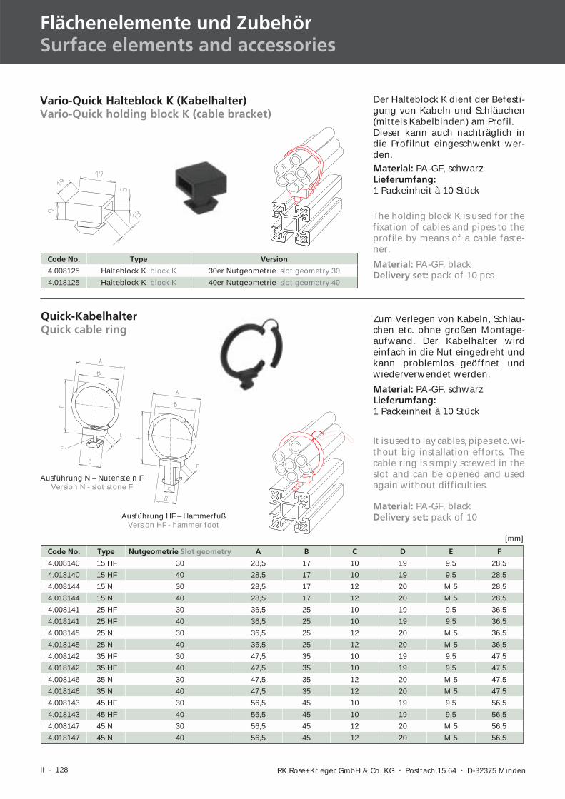
Vario-Quick Halteblock K (Kabelhalter)Vario-Quick holding block K (cable bracket)
Quick-KabelhalterQuick cable ring
Der Halteblock K dient der Befesti-gung von Kabeln und Schläuchen(mittels Kabelbinden) am Profil.Dieser kann auch nachträglich indie Profilnut eingeschwenkt wer-den.Material: PA-GF, schwarzLieferumfang:1 Packeinheit à 10 Stück
Zum Verlegen von Kabeln, Schläu-chen etc. ohne großen Montage-aufwand. Der Kabelhalter wirdeinfach in die Nut eingedreht undkann problemlos geöffnet undwiederverwendet werden.
Code No. Type Version
4.008125 Halteblock K block K 30er Nutgeometrie slot geometry 30
4.018125 Halteblock K block K 40er Nutgeometrie slot geometry 40
Material: PA-GF, schwarzLieferumfang:1 Packeinheit à 10 Stück
Ausführung N – Nutenstein FVersion N - slot stone F
The holding block K is used for thefixation of cables and pipes to theprofile by means of a cable faste-ner.
Material: PA-GF, blackDelivery set: pack of 10 pcs
It is used to lay cables, pipes etc. wi-thout big installation efforts. Thecable ring is simply screwed in theslot and can be opened and usedagain without difficulties.
Code No. Type Nutgeometrie Slot geometry A B C D E F
4.008140 15 HF 30 28,5 17 10 19 9,5 28,5
4.018140 15 HF 40 28,5 17 10 19 9,5 28,5
4.008144 15 N 30 28,5 17 12 20 M 5 28,5
4.018144 15 N 40 28,5 17 12 20 M 5 28,5
4.008141 25 HF 30 36,5 25 10 19 9,5 36,5
4.018141 25 HF 40 36,5 25 10 19 9,5 36,5
4.008145 25 N 30 36,5 25 12 20 M 5 36,5
4.018145 25 N 40 36,5 25 12 20 M 5 36,5
4.008142 35 HF 30 47,5 35 10 19 9,5 47,5
4.018142 35 HF 40 47,5 35 10 19 9,5 47,5
4.008146 35 N 30 47,5 35 12 20 M 5 47,5
4.018146 35 N 40 47,5 35 12 20 M 5 47,5
4.008143 45 HF 30 56,5 45 10 19 9,5 56,5
4.018143 45 HF 40 56,5 45 10 19 9,5 56,5
4.008147 45 N 30 56,5 45 12 20 M 5 56,5
4.018147 45 N 40 56,5 45 12 20 M 5 56,5
[mm]
Ausführung HF – HammerfußVersion HF - hammer foot
Material: PA-GF, blackDelivery set: pack of 10
II - 129
I
II
IV
III
V
VID-BL 10/2003
II - 130 RK Rose+Krieger GmbH & Co. KG � Postfach 15 64 � D-32375 Minden
Flächenelemente und ZubehörSurface elements and accessories
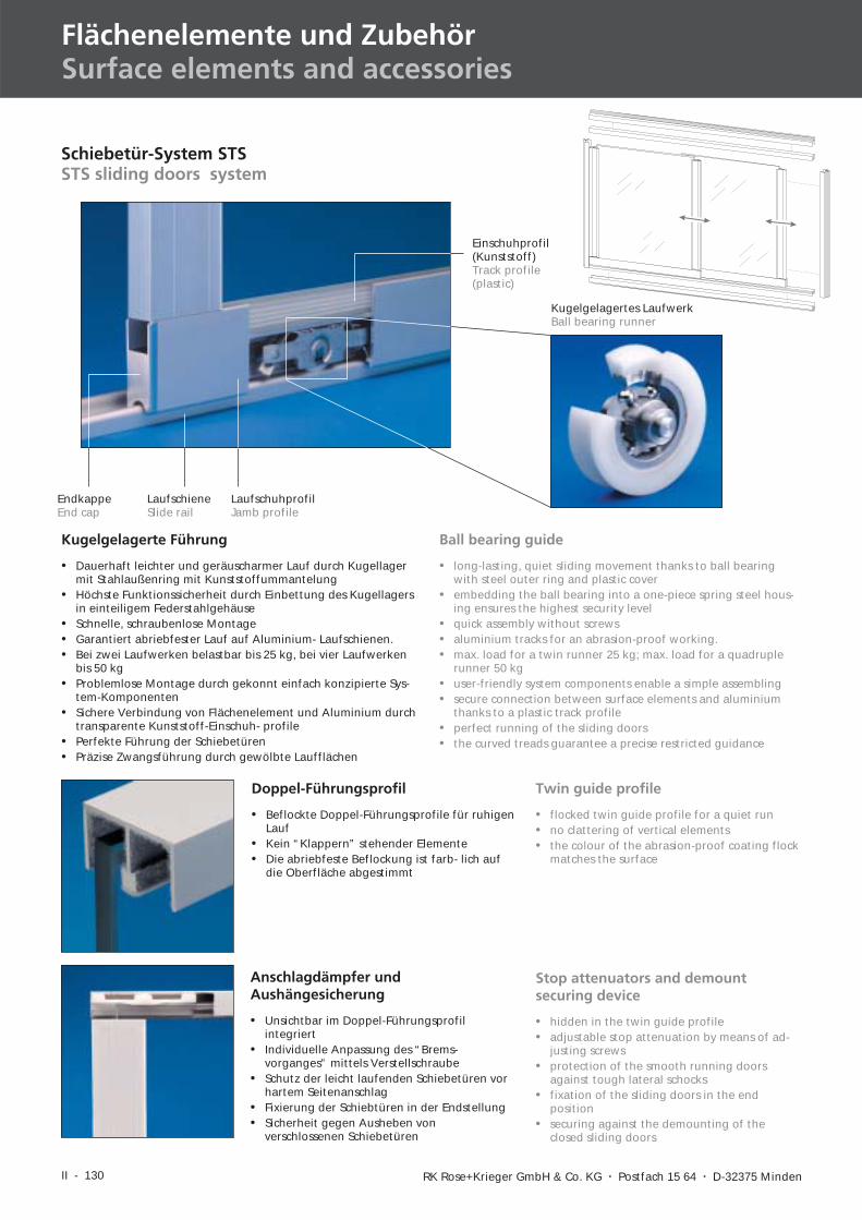
Kugelgelagerte Führung
• Dauerhaft leichter und geräuscharmer Lauf durch Kugellagermit Stahlaußenring mit Kunststoffummantelung
• Höchste Funktionssicherheit durch Einbettung des Kugellagersin einteiligem Federstahlgehäuse
• Schnelle, schraubenlose Montage• Garantiert abriebfester Lauf auf Aluminium- Laufschienen.• Bei zwei Laufwerken belastbar bis 25 kg, bei vier Laufwerken
bis 50 kg• Problemlose Montage durch gekonnt einfach konzipierte Sys-
tem-Komponenten• Sichere Verbindung von Flächenelement und Aluminium durch
transparente Kunststoff-Einschuh- profile• Perfekte Führung der Schiebetüren• Präzise Zwangsführung durch gewölbte Laufflächen
Ball bearing guide
• long-lasting, quiet sliding movement thanks to ball bearingwith steel outer ring and plastic cover
• embedding the ball bearing into a one-piece spring steel hous-ing ensures the highest security level
• quick assembly without screws• aluminium tracks for an abrasion-proof working.• max. load for a twin runner 25 kg; max. load for a quadruple
runner 50 kg• user-friendly system components enable a simple assembling• secure connection between surface elements and aluminium
thanks to a plastic track profile• perfect running of the sliding doors• the curved treads guarantee a precise restricted guidance
LaufschieneSlide rail
LaufschuhprofilJamb profile
EndkappeEnd cap
Kugelgelagertes LaufwerkBall bearing runner
Einschuhprofil(Kunststoff)Track profile(plastic)
Schiebetür-System STSSTS sliding doors system
Doppel-Führungsprofil
• Beflockte Doppel-Führungsprofile für ruhigenLauf
• Kein “Klappern” stehender Elemente• Die abriebfeste Beflockung ist farb- lich auf
die Oberfläche abgestimmt
Twin guide profile
• flocked twin guide profile for a quiet run• no clattering of vertical elements• the colour of the abrasion-proof coating flock
matches the surface
Stop attenuators and demountsecuring device
• hidden in the twin guide profile• adjustable stop attenuation by means of ad-
justing screws• protection of the smooth running doors
against tough lateral schocks• fixation of the sliding doors in the end
position• securing against the demounting of the
closed sliding doors
Anschlagdämpfer undAushängesicherung
• Unsichtbar im Doppel-Führungsprofilintegriert
• Individuelle Anpassung des “Brems-vorganges” mittels Verstellschraube
• Schutz der leicht laufenden Schiebetüren vorhartem Seitenanschlag
• Fixierung der Schiebtüren in der Endstellung• Sicherheit gegen Ausheben von
verschlossenen Schiebetüren
II - 131
I
II
IV
III
V
VID-BL 10/2003
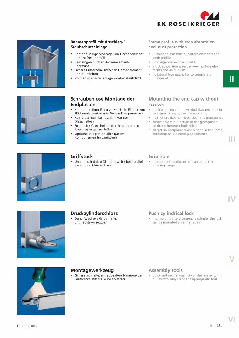
Rahmenprofil mit Anschlag-/Staubschutzeinlage
• Kantenbündige Montage von Flächenelementund Laufschuhprofil
• Kein ungeschützter Flächenelement-überstand
• Sichere Pufferzone zwischen Flächenelementund Aluminium
• Vollflächige Seitenanlage – daher staubdicht
Frame profile with stop absorptionand dust protection
• flush-edge assembly of surface elements andjamb profile
• no dangerous exposed parts• shock absoprtion area between surface ele-
ments and aluminium• no lateral free space, hence completely
dust-proof
Schraubenlose Montage derEndplatten• Kantenbündiger Einsatz – vertikale Einheit von
Flächenelementen und System-Komponenten• Kein Ausbruch, kein Ausklinken der
Glasscheiben• Schutz der Glasscheiben durch beidseitigen
Anschlag in ganzer Höhe• Optische Integration aller System-
Komponenten im Laufschuh
Mounting the end cap withoutscrews• flush-edge insertion - vertical flatness of surfa-
ce elements and system components• neither breakes nor notches on the glass panes• whole height protection of the glass panes
against schocks on both sides• all system components are hidden in the jamb
confering an outstaning appearance
Griffstück• Uneingeschränkte Öffnungsweite bei parallel
stehenden Schiebetüren
Grip hole• no exposed handles enable an unlimited
opening range
Druckzylinderschloss• Durch Wechselzylinder links
und rechts einsetzbar
Push cylindrical lock• thanks to its interchangeable cylinder the lock
can be mounted on either sides
Montagewerkzeug• Sichere, schnelle, schraubenlose Montage der
Laufwerke mittels Laufwerksetzer
Assembly tools• quick and secure assembly of the runner with-
out screws, only using the appropriate tool
II - 132 RK Rose+Krieger GmbH & Co. KG � Postfach 15 64 � D-32375 Minden
Flächenelemente und ZubehörSurface elements and accessories
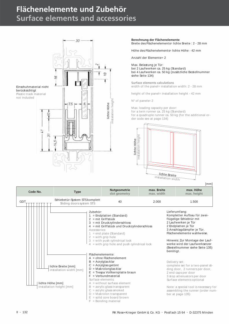
Zubehör:1 = Endplatten (Standard)2 = mit Griffstück3 = mit Druckzylinderschloss4 = mit Griffstück und DruckzylinderschlossAccessories:1 = end plate (Standard)2 = with grip hole3 = with push cylindrical lock4 = with grip hole and push cylindrical lock
lichte Breite [mm]installation width [mm]
lichte Höhe [mm]installation height [mm]
Lieferumfang:Kompletter Aufbau für zwei-flügelige Schiebtür mit2 Laufwerken je Tür2 Endplatten je Tür3 Anschlagdämpfer je Tür.Flächenelemente wahlweise.
Hinweis: Zur Montage der Lauf-werke wird der Laufwerksetzer(Bestellnummer siehe Seite 135)benötigt.
Delivery set:complete set for a two-panel sli-ding door, 2 runners per door,2 end caps per door3 stop attenuators per doorSurface elements optional
Note: a special tool is necessary forassembling the runner (order num-ber at page 135)
lich
teH
öh
ein
stal
atio
nh
eig
ht
Berechnung der FlächenelementeBreite des Flächenelements= lichte Breite : 2 - 28 mm
Höhe des Flächenelements= lichte Höhe - 42 mm
Anzahl der Elemente= 2
Max. Belastung je Tür:bei 2 Laufwerken ca. 25 kg (Standard)bei 4 Laufwerken ca. 50 kg (zusätzliche Bestellnummersiehe Seite 134)
Surface elements calculationswidth of the panel= installation width: 2 - 28 mm
height of the panel= installation height - 42 mm
N° of panels= 2
Max. loading capacity per door:for a twin runner ca. 25 kg (Standard)for a quadruple runner ca. 50 kg (for the additional or-der code see at page 134)
Einschuhmaterial nichtberücksichtigtPlastic track materialnot included
Flächenelemente:A = ohne FlächenelementB = Acrylglas klarC = Acrylglas getöntD = Makrolonglas klarE = Trespa Vollkernplatte braunF = VerbundmaterialSurface elements:A = without surface elementB = acrylic glass transparentC = acrylic glass smokedD = Makrolon transparentE = solid core board brownF = Bonding material
lich
teH
öh
ein
stal
atio
nh
eig
ht
lichte Breiteinstallation width
Code No. Type Nutgeometrieslot geometry
max. Breitemax. width
max. Höhemax. height
GDT_ _ _ _ _ _ _ _ _ _ Schiebetür-System STS komplettSliding doors system STS 40 2.000 1.500
[mm]
II - 133
I
II
IV
III
V
VID-BL 10/2003
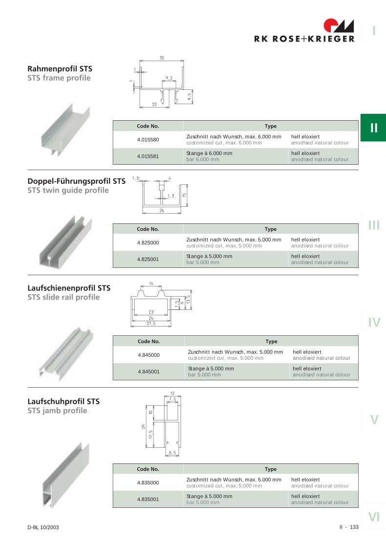
Code No. Type
4.015580 Zuschnitt nach Wunsch, max. 6.000 mmcustomized cut, max. 6.000 mm
hell eloxiertanodised natural colour
4.015581 Stange à 6.000 mmbar 6.000 mm
hell eloxiertanodised natural colour
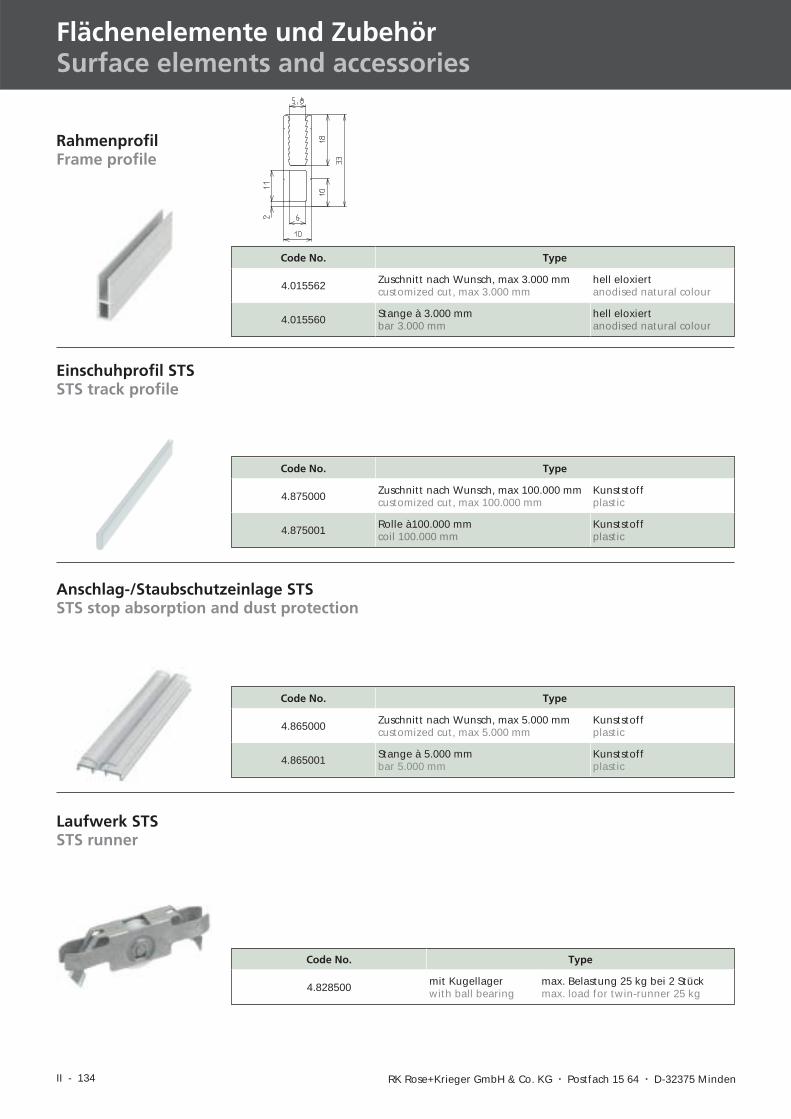
Rahmenprofil STSSTS frame profile
Doppel-Führungsprofil STSSTS twin guide profile
Code No. Type
4.825000 Zuschnitt nach Wunsch, max. 5.000 mmcustomized cut, max. 5.000 mm
hell eloxiertanodised natural colour
4.825001 Stange à 5.000 mmbar 5.000 mm
hell eloxiertanodised natural colour
Code No. Type
4.845000 Zuschnitt nach Wunsch, max. 5.000 mmcustomized cut, max. 5.000 mm
hell eloxiertanodised natural colour
4.845001 Stange à 5.000 mmbar 5.000 mm
hell eloxiertanodised natural colour
Laufschienenprofil STSSTS slide rail profile
Laufschuhprofil STSSTS jamb profile
Code No. Type
4.835000 Zuschnitt nach Wunsch, max. 5.000 mmcustomized cut, max. 5.000 mm
hell eloxiertanodised natural colour
4.835001 Stange à 5.000 mmbar 5.000 mm
hell eloxiertanodised natural colour
II - 134 RK Rose+Krieger GmbH & Co. KG � Postfach 15 64 � D-32375 Minden
Flächenelemente und ZubehörSurface elements and accessories
Code No. Type
4.865000 Zuschnitt nach Wunsch, max 5.000 mmcustomized cut, max 5.000 mm
Kunststoffplastic
4.865001 Stange à 5.000 mmbar 5.000 mm
Kunststoffplastic
Anschlag-/Staubschutzeinlage STSSTS stop absorption and dust protection
Einschuhprofil STSSTS track profile
Code No. Type
4.875000 Zuschnitt nach Wunsch, max 100.000 mmcustomized cut, max 100.000 mm
Kunststoffplastic
4.875001 Rolle à100.000 mmcoil 100.000 mm
Kunststoffplastic
Code No. Type
4.015562 Zuschnitt nach Wunsch, max 3.000 mmcustomized cut, max 3.000 mm
hell eloxiertanodised natural colour
4.015560 Stange à 3.000 mmbar 3.000 mm
hell eloxiertanodised natural colour
RahmenprofilFrame profile
Laufwerk STSSTS runner
Code No. Type
4.828500 mit Kugellagerwith ball bearing
max. Belastung 25 kg bei 2 Stückmax. load for twin-runner 25 kg
II - 135
I
II
IV
III
V
VID-BL 10/2003
Anschlagdämpfer/Aushängesicherung STSSTS Stop attenuator and demount securing device
Code No. Type
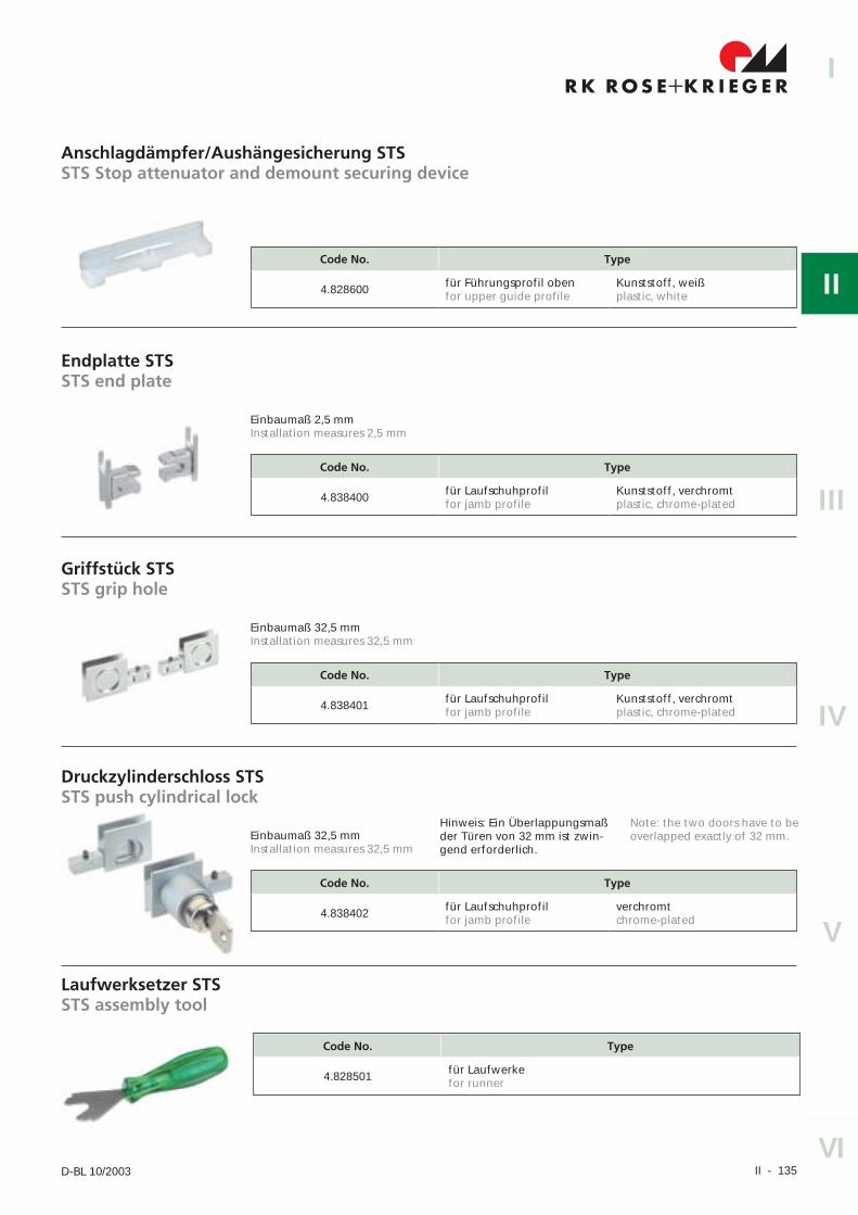
4.828600 für Führungsprofil obenfor upper guide profile
Kunststoff, weißplastic, white
Code No. Type
4.838400 für Laufschuhprofilfor jamb profile
Kunststoff, verchromtplastic, chrome-plated
Endplatte STSSTS end plate
Griffstück STSSTS grip hole
Code No. Type
4.838401 für Laufschuhprofilfor jamb profile
Kunststoff, verchromtplastic, chrome-plated
Druckzylinderschloss STSSTS push cylindrical lock
Einbaumaß 32,5 mmInstallation measures 32,5 mm
Einbaumaß 2,5 mmInstallation measures 2,5 mm
Einbaumaß 32,5 mmInstallation measures 32,5 mm
Laufwerksetzer STSSTS assembly tool
Code No. Type
4.838402 für Laufschuhprofilfor jamb profile
verchromtchrome-plated
Hinweis: Ein Überlappungsmaßder Türen von 32 mm ist zwin-gend erforderlich.
Note: the two doors have to beoverlapped exactly of 32 mm.
Code No. Type
4.828501 für Laufwerkefor runner
II - 136 RK Rose+Krieger GmbH & Co. KG � Postfach 15 64 � D-32375 Minden
Flächenelemente und ZubehörSurface elements and accessories
SchiebetürprofilSliding door profile
Code No. Type Nutgeometrie Slot geometry A B C D E
mit Rundstab with bead-moulding
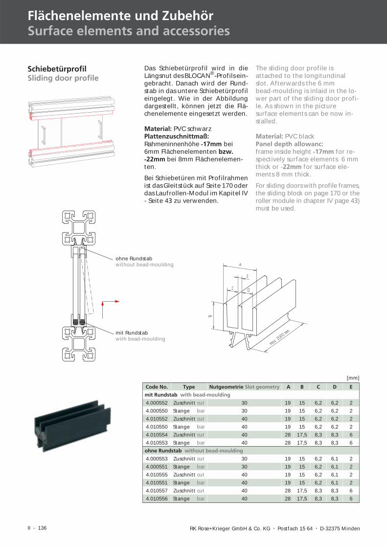
4.000552 Zuschnitt cut 30 19 15 6,2 6,2 2
4.000550 Stange bar 30 19 15 6,2 6,2 2
4.010552 Zuschnitt cut 40 19 15 6,2 6,2 2
4.010550 Stange bar 40 19 15 6,2 6,2 2
4.010554 Zuschnitt cut 40 28 17,5 8,3 8,3 6
4.010553 Stange bar 40 28 17,5 8,3 8,3 6
ohne Rundstab without bead-moulding
4.000553 Zuschnitt cut 30 19 15 6,2 6,1 2
4.000551 Stange bar 30 19 15 6,2 6,1 2
4.010555 Zuschnitt cut 40 19 15 6,2 6,1 2
4.010551 Stange bar 40 19 15 6,2 6,1 2
4.010557 Zuschnitt cut 40 28 17,5 8,3 8,3 6
4.010556 Stange bar 40 28 17,5 8,3 8,3 6
[mm]
Das Schiebetürprofil wird in dieLängsnut des BLOCAN®-Profils ein-gebracht. Danach wird der Rund-stab in das untere Schiebetürprofileingelegt. Wie in der Abbildungdargestellt, können jetzt die Flä-chenelemente eingesetzt werden.
Material: PVC schwarzPlattenzuschnittmaß:Rahmeninnenhöhe -17mm bei6mm Flächenelementen bzw.
-22mm bei 8mm Flächenelemen-ten.
Bei Schiebetüren mit Profilrahmenist das Gleitstück auf Seite 170 oderdas Laufrollen-Modul im Kapitel IV- Seite 43 zu verwenden.
The sliding door profile isattached to the longitundinalslot. Afterwards the 6 mmbead-moulding is inlaid in the lo-wer part of the sliding door profi-le. As shown in the picturesurface elements can be now in-stalled.
Material: PVC blackPanel depth allowanc:frame inside height -17mm for re-spectively surface elements 6 mmthick or -22mm for surface ele-ments 8 mm thick.
For sliding doors with profile frames,the sliding block on page 170 or theroller module in chapter IV page 43)must be used.
mit Rundstabwith bead-moulding
ohne Rundstabwithout bead-moulding
II - 137
I
II
IV
III
V
VID-BL 10/2003
II - 138 RK Rose+Krieger GmbH & Co. KG � Postfach 15 64 � D-32375 Minden
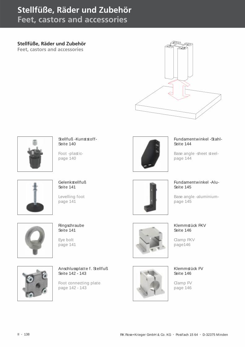
Stellfüße, Räder und ZubehörFeet, castors and accessories
Stellfuß -Kunststoff-Seite 140
Foot -plastic-page 140
GelenkstellfußSeite 141
Levelling footpage 141
RingschraubeSeite 141
Eye boltpage 141
Anschlussplatte f. StellfußSeite 142 - 143
Foot connecting platepage 142 - 143
Klemmstück FVSeite 146
Clamp FVpage 146
Klemmstück FKVSeite 146
Clamp FKVpage146
Fundamentwinkel -Stahl-Seite 144
Base angle -sheet steel-page 144
Fundamentwinkel -Alu-Seite 145
Base angle -aluminium-page 145
Stellfüße, Räder und ZubehörFeet, castors and accessories
II - 139
I
II
IV
III
V
VID-BL 10/2003
BockrolleSeite 149
Fixed castorpage 149
FußplatteSeite 147
Base platepage 147
LenkrolleSeite 148
Lockable swivel castorpage 148
Fußstütze FSHSeite 150
Foot rest FSHpage 150
II - 140 RK Rose+Krieger GmbH & Co. KG � Postfach 15 64 � D-32375 Minden
Stellfüße, Räder und ZubehörFeet, castors and accessories
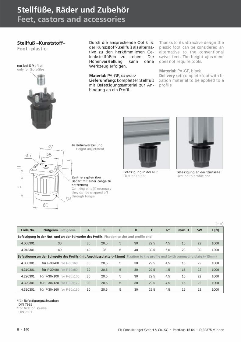
Stellfuß –Kunststoff–Foot –plastic–
F
Code No. Nutgeom. Slot geom. A B C D E G* max. H SW F [N]
Befestigung in der Nut und an der Stirnseite des Profils Fixation to slot and profile end
4.008301 30 30 20,5 5 30 29,5 4,5 15 22 1000
4.018301 40 40 28 5 40 39,5 6,6 23 30 1200
Befestigung an der Stirnseite des Profils (mit Anschlussplatte t=15mm) Fixation to the profile end (with connecting plate t=15mm)
4.300301 für F-30x60 for F-30x60 30 20,5 5 30 29,5 4,5 15 22 1000
4.310301 für F-30x80 for F-30x80 30 20,5 5 30 29,5 4,5 15 22 1000
4.290301 für F-30x100 for F-30x100 30 20,5 5 30 29,5 4,5 15 22 1000
4.320301 für F-30x120 for F-30x120 30 20,5 5 30 29,5 4,5 15 22 1000
4.330301 für F-30x160 for F-30x160 30 20,5 5 30 29,5 4,5 15 22 1000
[mm]
Zentrierzapfen (beiBedarf mit einer Zange zuentfernen)Centring pins (if necessarythey can be snapped offthrough tongs)
H= HöhenverstellungHeight adjustment
*für BefestigungsschraubenDIN 7991
*for fixation screwsDIN 7991
Befestigung an der StirnseiteFixation to profile end
Befestigung in der NutFixation to slot
Durch die ansprechende Optik istder Kunststoff-Stellfuß als alterna-tive zu den herkömmlichen Ge-lenkstellfüßen zu sehen. DieHöhenverstellung kann ohneWerkzeug erfolgen.
Material: PA-GF, schwarzLieferumfang: kompletter Stellfußmit Befestigungsamterial zur An-bindung an ein Profil.
Thanks to its attractive design theplastic foot can be considered analternative to the conventionalswivel feet. The height ajustmentdoes not require tools.
Material: PA-GF, blackDelivery set: complete foot with fi-xation material to be applied to aprofile
nur bei S-Profilenonly for S-profiles
II - 141
I
II
IV
III
V
VID-BL 04/2005
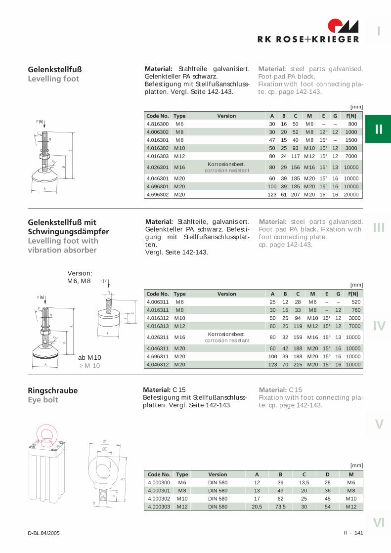
Material: steel parts galvanised.Foot pad PA black.Fixation with foot connecting pla-te. cp. page 142-143.
GelenkstellfußLevelling foot
Code No. Type Version A B C M E G F[N]
4.816300 M6 30 16 50 M6 – – 800
4.006302 M8 30 20 52 M8 12° 12 1000
4.016301 M8 47 15 40 M8 15° – 1500
4.016302 M10 50 25 93 M10 15° 12 3000
4.016303 M12 80 24 117 M12 15° 12 7000
4.026301 M16 Korrosionsbest.corrosion resistant 80 29 156 M16 15° 13 10000
4.046301 M20 60 39 185 M20 15° 16 10000
4.696301 M20 100 39 185 M20 15° 16 10000
4.696302 M20 123 61 207 M20 15° 16 20000
[mm]
Gelenkstellfuß mitSchwingungsdämpferLevelling foot withvibration absorber
Material: Stahlteile, galvanisiert.Gelenkteller PA schwarz. Befesti-gung mit Stellfußanschlussplat-ten.Vergl. Seite 142-143.
Code No. Type Version A B C M E G F[N]
4.006311 M6 25 12 28 M6 – – 520
4.016311 M8 30 15 33 M8 – 12 760
4.016312 M10 50 25 94 M10 15° 12 3000
4.016313 M12 80 26 119 M12 15° 12 7000
4.026311 M16 Korrosionsbest.corrosion resistant 80 32 159 M16 15° 13 10000
4.046311 M20 60 42 188 M20 15° 16 10000
4.696311 M20 100 39 188 M20 15° 16 10000
4.046312 M20 123 70 215 M20 15° 16 10000
[mm]
RingschraubeEye bolt
Code No. Type Version A B C D M
4.000300 M6 DIN 580 12 39 13,5 28 M6
4.000301 M8 DIN 580 13 49 20 36 M8
4.000302 M10 DIN 580 17 62 25 45 M10
4.000303 M12 DIN 580 20,5 73,5 30 54 M12
[mm]
Material: C 15Befestigung mit Stellfußanschluss-platten. Vergl. Seite 142-143.
ab M10� M 10
Material: Stahlteile galvanisiert.Gelenkteller PA schwarz.Befestigung mit Stellfußanschluss-platten. Vergl. Seite 142-143.
Material: steel parts galvanised.Foot pad PA black. Fixation withfoot connecting plate.cp. page 142-143.
Material: C 15Fixation with foot connecting pla-te. cp. page 142-143.
Version:M6, M8
II - 142 RK Rose+Krieger GmbH � Postfach 15 64 � D-32375 Minden
Stellfüße, Räder und ZubehörFeet, castors and accessories
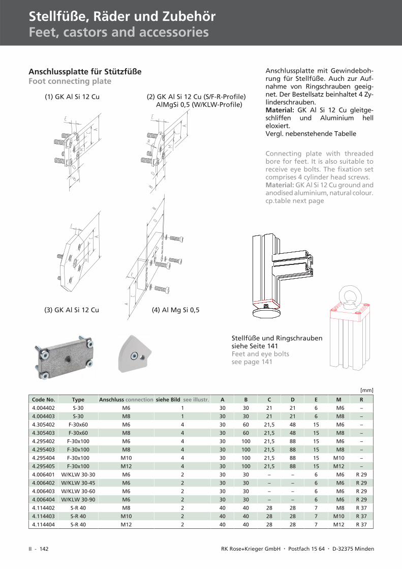
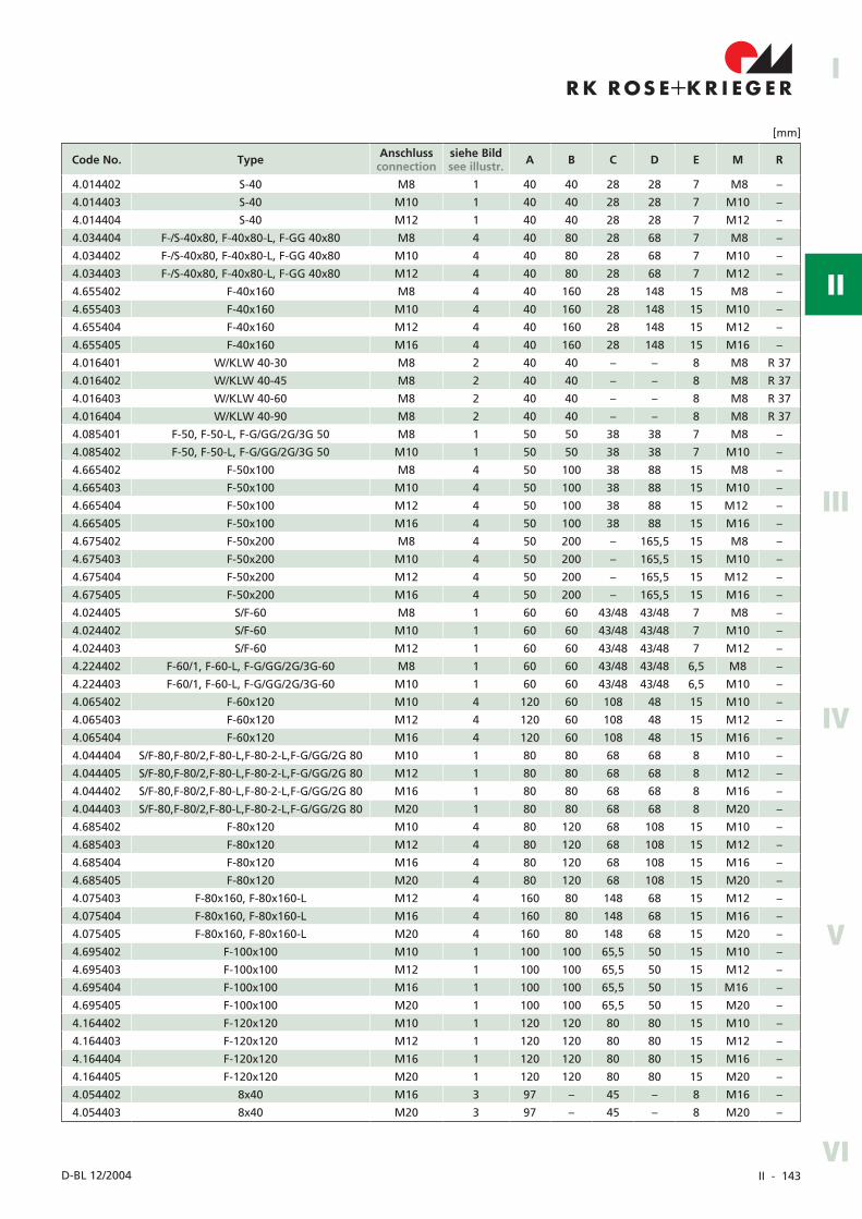
Anschlussplatte für StützfüßeFoot connecting plate
Anschlussplatte mit Gewindeboh-rung für Stellfüße. Auch zur Auf-nahme von Ringschrauben geeig-net. Der Bestellsatz beinhaltet 4 Zy-linderschrauben.Material: GK Al Si 12 Cu gleitge-schliffen und Aluminium helleloxiert.Vergl. nebenstehende Tabelle
(1) GK Al Si 12 Cu (2) GK Al Si 12 Cu (S/F-R-Profile)AlMgSi 0,5 (W/KLW-Profile)
(3) GK Al Si 12 Cu (4) Al Mg Si 0,5
Code No. Type Anschluss connection siehe Bild see illustr. A B C D E M R
4.004402 S-30 M6 1 30 30 21 21 6 M6 –
4.004403 S-30 M8 1 30 30 21 21 6 M8 –
4.305402 F-30x60 M6 4 30 60 21,5 48 15 M6 –
4.305403 F-30x60 M8 4 30 60 21,5 48 15 M8 –
4.295402 F-30x100 M6 4 30 100 21,5 88 15 M6 –
4.295403 F-30x100 M8 4 30 100 21,5 88 15 M8 –
4.295404 F-30x100 M10 4 30 100 21,5 88 15 M10 –
4.295405 F-30x100 M12 4 30 100 21,5 88 15 M12 –
4.006401 W/KLW 30-30 M6 2 30 30 – – 6 M6 R 29
4.006402 W/KLW 30-45 M6 2 30 30 – – 6 M6 R 29
4.006403 W/KLW 30-60 M6 2 30 30 – – 6 M6 R 29
4.006404 W/KLW 30-90 M6 2 30 30 – – 6 M6 R 29
4.114402 S-R 40 M8 2 40 40 28 28 7 M8 R 37
4.114403 S-R 40 M10 2 40 40 28 28 7 M10 R 37
4.114404 S-R 40 M12 2 40 40 28 28 7 M12 R 37
[mm]
Connecting plate with threadedbore for feet. It is also suitable toreceive eye bolts. The fixation setcomprises 4 cylinder head screws.Material: GK Al Si 12 Cu ground andanodised aluminium, natural colour.cp.table next page
Stellfüße und Ringschraubensiehe Seite 141Feet and eye boltssee page 141
II - 143
R K R OS E K R I EG E R+I
II
IV
III
V
VID-BL 12/2004
Code No. Type Anschlussconnection
siehe Bildsee illustr. A B C D E M R
4.014402 S-40 M8 1 40 40 28 28 7 M8 –
4.014403 S-40 M10 1 40 40 28 28 7 M10 –
4.014404 S-40 M12 1 40 40 28 28 7 M12 –
4.034404 F-/S-40x80, F-40x80-L, F-GG 40x80 M8 4 40 80 28 68 7 M8 –
4.034402 F-/S-40x80, F-40x80-L, F-GG 40x80 M10 4 40 80 28 68 7 M10 –
4.034403 F-/S-40x80, F-40x80-L, F-GG 40x80 M12 4 40 80 28 68 7 M12 –
4.655402 F-40x160 M8 4 40 160 28 148 15 M8 –
4.655403 F-40x160 M10 4 40 160 28 148 15 M10 –
4.655404 F-40x160 M12 4 40 160 28 148 15 M12 –
4.655405 F-40x160 M16 4 40 160 28 148 15 M16 –
4.016401 W/KLW 40-30 M8 2 40 40 – – 8 M8 R 37
4.016402 W/KLW 40-45 M8 2 40 40 – – 8 M8 R 37
4.016403 W/KLW 40-60 M8 2 40 40 – – 8 M8 R 37
4.016404 W/KLW 40-90 M8 2 40 40 – – 8 M8 R 37
4.085401 F-50, F-50-L, F-G/GG/2G/3G 50 M8 1 50 50 38 38 7 M8 –
4.085402 F-50, F-50-L, F-G/GG/2G/3G 50 M10 1 50 50 38 38 7 M10 –
4.665402 F-50x100 M8 4 50 100 38 88 15 M8 –
4.665403 F-50x100 M10 4 50 100 38 88 15 M10 –
4.665404 F-50x100 M12 4 50 100 38 88 15 M12 –
4.665405 F-50x100 M16 4 50 100 38 88 15 M16 –
4.675402 F-50x200 M8 4 50 200 – 165,5 15 M8 –
4.675403 F-50x200 M10 4 50 200 – 165,5 15 M10 –
4.675404 F-50x200 M12 4 50 200 – 165,5 15 M12 –
4.675405 F-50x200 M16 4 50 200 – 165,5 15 M16 –
4.024405 S/F-60 M8 1 60 60 43/48 43/48 7 M8 –
4.024402 S/F-60 M10 1 60 60 43/48 43/48 7 M10 –
4.024403 S/F-60 M12 1 60 60 43/48 43/48 7 M12 –
4.224402 F-60/1, F-60-L, F-G/GG/2G/3G-60 M8 1 60 60 43/48 43/48 6,5 M8 –
4.224403 F-60/1, F-60-L, F-G/GG/2G/3G-60 M10 1 60 60 43/48 43/48 6,5 M10 –
4.065402 F-60x120 M10 4 120 60 108 48 15 M10 –
4.065403 F-60x120 M12 4 120 60 108 48 15 M12 –
4.065404 F-60x120 M16 4 120 60 108 48 15 M16 –
4.044404 S/F-80,F-80/2,F-80-L,F-80-2-L,F-G/GG/2G 80 M10 1 80 80 68 68 8 M10 –
4.044405 S/F-80,F-80/2,F-80-L,F-80-2-L,F-G/GG/2G 80 M12 1 80 80 68 68 8 M12 –
4.044402 S/F-80,F-80/2,F-80-L,F-80-2-L,F-G/GG/2G 80 M16 1 80 80 68 68 8 M16 –
4.044403 S/F-80,F-80/2,F-80-L,F-80-2-L,F-G/GG/2G 80 M20 1 80 80 68 68 8 M20 –
4.685402 F-80x120 M10 4 80 120 68 108 15 M10 –
4.685403 F-80x120 M12 4 80 120 68 108 15 M12 –
4.685404 F-80x120 M16 4 80 120 68 108 15 M16 –
4.685405 F-80x120 M20 4 80 120 68 108 15 M20 –
4.075403 F-80x160, F-80x160-L M12 4 160 80 148 68 15 M12 –
4.075404 F-80x160, F-80x160-L M16 4 160 80 148 68 15 M16 –
4.075405 F-80x160, F-80x160-L M20 4 160 80 148 68 15 M20 –
4.695402 F-100x100 M10 1 100 100 65,5 50 15 M10 –
4.695403 F-100x100 M12 1 100 100 65,5 50 15 M12 –
4.695404 F-100x100 M16 1 100 100 65,5 50 15 M16 –
4.695405 F-100x100 M20 1 100 100 65,5 50 15 M20 –
4.164402 F-120x120 M10 1 120 120 80 80 15 M10 –
4.164403 F-120x120 M12 1 120 120 80 80 15 M12 –
4.164404 F-120x120 M16 1 120 120 80 80 15 M16 –
4.164405 F-120x120 M20 1 120 120 80 80 15 M20 –
4.054402 8x40 M16 3 97 – 45 – 8 M16 –
4.054403 8x40 M20 3 97 – 45 – 8 M20 –
[mm]
II - 144 RK Rose+Krieger GmbH � Postfach 15 64 � D-32375 Minden
Stellfüße, Räder und ZubehörFeet, castors and accessories
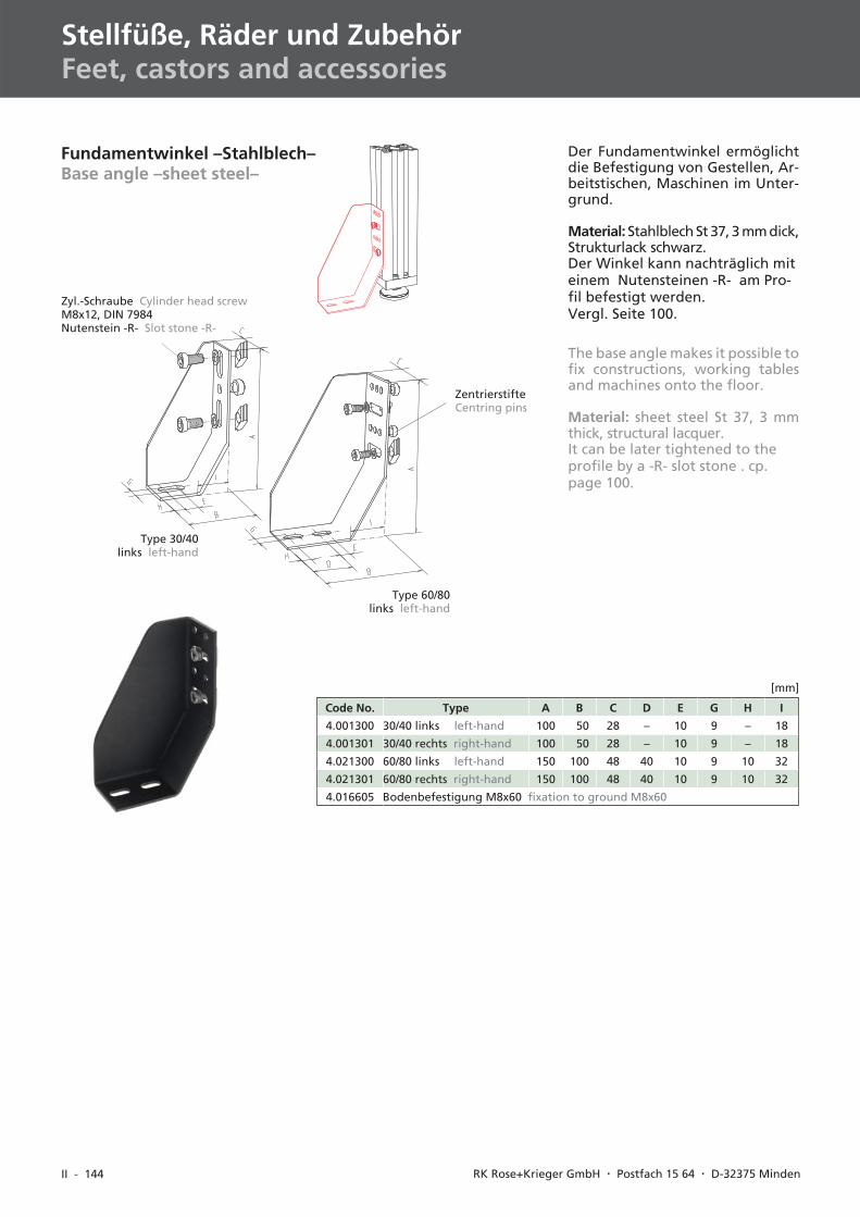
The base angle makes it possible tofix constructions, working tablesand machines onto the floor.
Material: sheet steel St 37, 3 mmthick, structural lacquer.It can be later tightened to theprofile by a -R- slot stone . cp.page 100.
Fundamentwinkel –Stahlblech–Base angle –sheet steel–
Der Fundamentwinkel ermöglichtdie Befestigung von Gestellen, Ar-beitstischen, Maschinen im Unter-grund.
Material: Stahlblech St 37, 3 mm dick,Strukturlack schwarz.Der Winkel kann nachträglich miteinem Nutensteinen -R- am Pro-fil befestigt werden.Vergl. Seite 100.
Code No. Type A B C D E G H I
4.001300 30/40 links left-hand 100 50 28 – 10 9 – 18
4.001301 30/40 rechts right-hand 100 50 28 – 10 9 – 18
4.021300 60/80 links left-hand 150 100 48 40 10 9 10 32
4.021301 60/80 rechts right-hand 150 100 48 40 10 9 10 32
4.016605 Bodenbefestigung M8x60 fixation to ground M8x60
[mm]
Type 30/40links left-hand
Type 60/80links left-hand
Zyl.-Schraube Cylinder head screwM8x12, DIN 7984Nutenstein -R- Slot stone -R-
ZentrierstifteCentring pins
II - 145
I
II
IV
III
V
VID-BL 10/2003
Code No. Type A B C D E F G H
4.011302 40er Nutgeometrie slot geometry 40 60 160 40 120 55 20 11 12
Befestigungssatz, Nutenstein -N- mit Schraube M8x20 DIN 912fixation set, slot stone -N- with screw M8x20 DIN 912
4.016604 Befestigungsanker M8x115 fixation to ground M8x115
[mm]
Zyl.-Schraube Cylinder head screwM8x20, DIN 912Nutenstein -N- Slot stone -N-
ZentrierstifteCentring pins
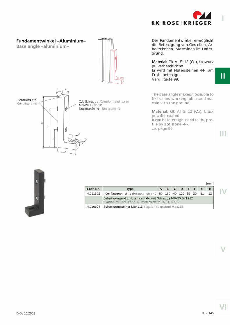
Fundamentwinkel –Aluminium–Base angle –aluminium–
Der Fundamentwinkel ermöglichtdie Befestigung von Gestellen, Ar-beitstischen, Maschinen im Unter-grund.
Material: Gk Al Si 12 (Cu), schwarzpulverbeschichtetEr wird mit Nutensteinen -N- amProfil befestigt.Vergl. Seite 99.
The base angle makes it possible tofix frames, working tables and ma-chines to the ground.
Material: Gk Al Si 12 (Cu), blackpowder-coatedIt can be later tightened to the pro-file by slot stone -N-.cp. page 99.
II - 146 RK Rose+Krieger GmbH & Co. KG � Postfach 15 64 � D-32375 Minden
Stellfüße, Räder und ZubehörFeet, castors and accessories
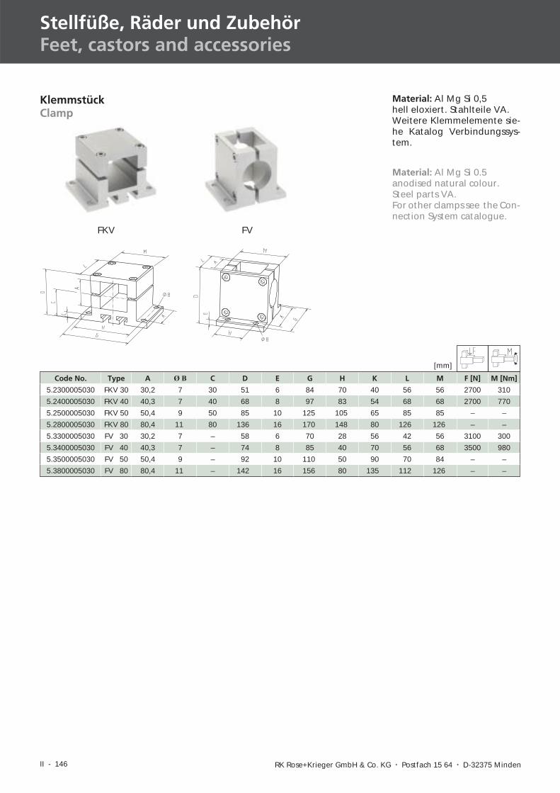
KlemmstückClamp
Material: Al Mg Si 0,5hell eloxiert. Stahlteile VA.Weitere Klemmelemente sie-he Katalog Verbindungssys-tem.
Code No. Type A Ø B C D E G H K L M F [N] M [Nm]
5.2300005030 FKV 30 30,2 7 30 51 6 84 70 40 56 56 2700 310
5.2400005030 FKV 40 40,3 7 40 68 8 97 83 54 68 68 2700 770
5.2500005030 FKV 50 50,4 9 50 85 10 125 105 65 85 85 – –
5.2800005030 FKV 80 80,4 11 80 136 16 170 148 80 126 126 – –
5.3300005030 FV 30 30,2 7 – 58 6 70 28 56 42 56 3100 300
5.3400005030 FV 40 40,3 7 – 74 8 85 40 70 56 68 3500 980
5.3500005030 FV 50 50,4 9 – 92 10 110 50 90 70 84 – –
5.3800005030 FV 80 80,4 11 – 142 16 156 80 135 112 126 – –
FKV FV
Material: Al Mg Si 0.5anodised natural colour.Steel parts VA.For other clamps see the Con-nection System catalogue.
[mm]
II - 147
R K R OS E K R I EG E R+I
II
IV
III
V
VID-BL 05/2004
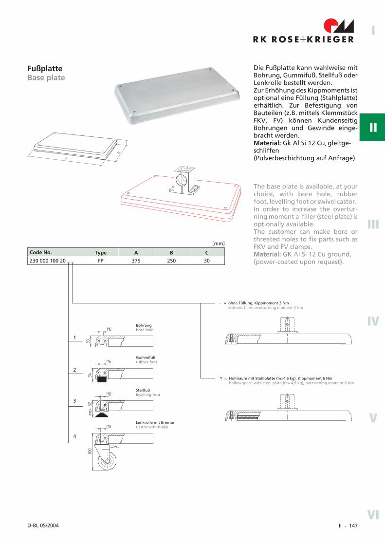
FußplatteBase plate
Code No. Type A B C
230 000 100 20 _ _ FP 375 250 30
[mm]
The base plate is available, at yourchoice, with bore hole, rubberfoot, levelling foot or swivel castor.In order to increase the overtur-ning moment a filler (steel plate) isoptionally available.The customer can make bore orthreated holes to fix parts such asFKV and FV clamps.Material: GK Al Si 12 Cu ground,(power-coated upon request).
Die Fußplatte kann wahlweise mitBohrung, Gummifuß, Stellfuß oderLenkrolle bestellt werden.Zur Erhöhung des Kippmoments istoptional eine Füllung (Stahlplatte)erhältlich. Zur Befestigung vonBauteilen (z.B. mittels KlemmstückFKV, FV) können KundenseitigBohrungen und Gewinde einge-bracht werden.Material: Gk Al Si 12 Cu, gleitge-schliffen(Pulverbeschichtung auf Anfrage)
Bohrungbore hole
Gummifußrubber foot
Lenkrolle mit BremseCastor with brake
Stellfußlevelling foot
1
2
4
– = ohne Füllung, Kippmoment 3 Nmwithout filler, overturning moment 3 Nm
Y = Hohlraum mit Stahlplatte (m=4,6 kg), Kippmoment 6 Nmhollow space with steel plate (m= 4,6 kg), overturning moment 6 Nm
3
II - 148 RK Rose+Krieger GmbH � Postfach 15 64 � D-32375 Minden
Stellfüße, Räder und ZubehörFeet, castors and accessories
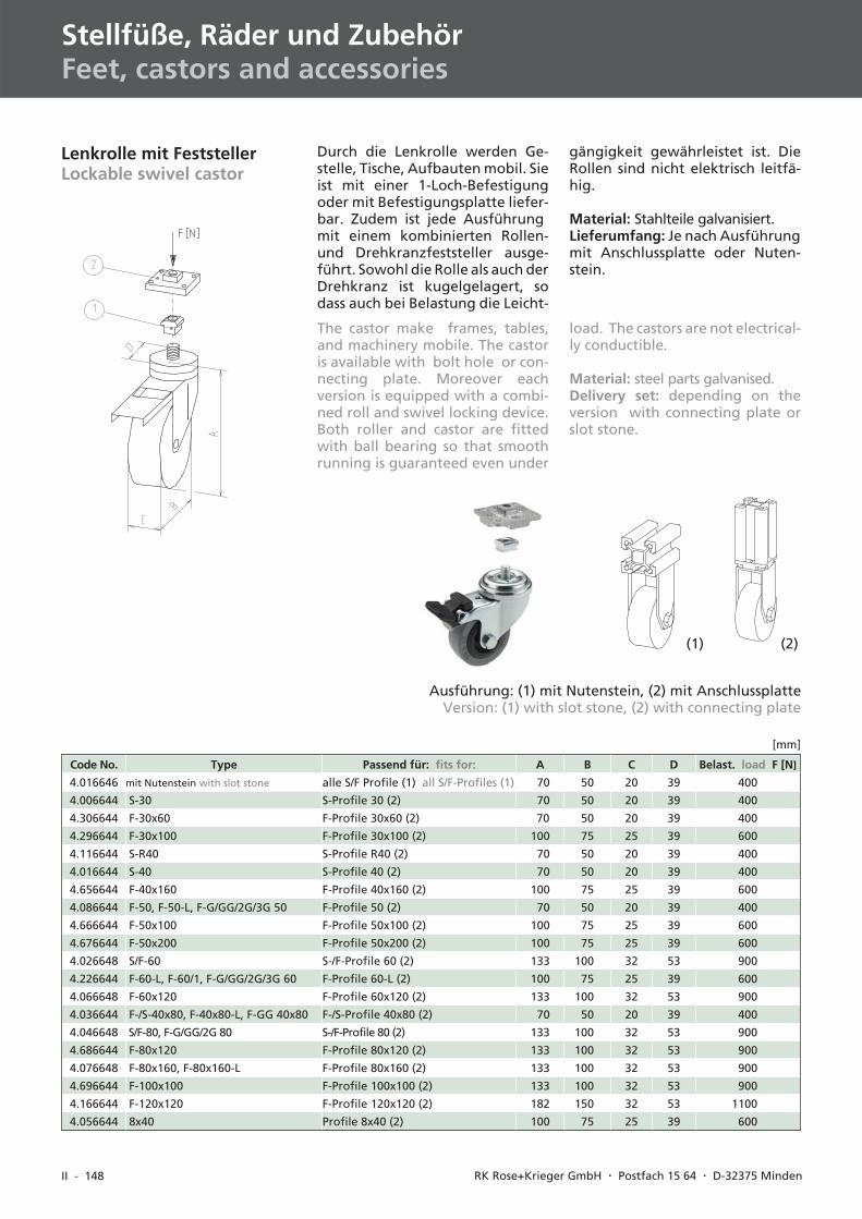
Lenkrolle mit FeststellerLockable swivel castor
Durch die Lenkrolle werden Ge-stelle, Tische, Aufbauten mobil. Sieist mit einer 1-Loch-Befestigungoder mit Befestigungsplatte liefer-bar. Zudem ist jede Ausführungmit einem kombinierten Rollen-und Drehkranzfeststeller ausge-führt. Sowohl die Rolle als auch derDrehkranz ist kugelgelagert, sodass auch bei Belastung die Leicht-
gängigkeit gewährleistet ist. DieRollen sind nicht elektrisch leitfä-hig.
Material: Stahlteile galvanisiert.Lieferumfang: Je nach Ausführungmit Anschlussplatte oder Nuten-stein.
The castor make frames, tables,and machinery mobile. The castoris available with bolt hole or con-necting plate. Moreover eachversion is equipped with a combi-ned roll and swivel locking device.Both roller and castor are fittedwith ball bearing so that smoothrunning is guaranteed even under
load. The castors are not electrical-ly conductible.
Material: steel parts galvanised.Delivery set: depending on theversion with connecting plate orslot stone.
(1) (2)
Ausführung: (1) mit Nutenstein, (2) mit AnschlussplatteVersion: (1) with slot stone, (2) with connecting plate
Code No. Type Passend für: fits for: A B C D Belast. load F [N]
4.016646 mit Nutenstein with slot stone alle S/F Profile (1) all S/F-Profiles (1) 70 50 20 39 400
4.006644 S-30 S-Profile 30 (2) 70 50 20 39 400
4.306644 F-30x60 F-Profile 30x60 (2) 70 50 20 39 400
4.296644 F-30x100 F-Profile 30x100 (2) 100 75 25 39 600
4.116644 S-R40 S-Profile R40 (2) 70 50 20 39 400
4.016644 S-40 S-Profile 40 (2) 70 50 20 39 400
4.656644 F-40x160 F-Profile 40x160 (2) 100 75 25 39 600
4.086644 F-50, F-50-L, F-G/GG/2G/3G 50 F-Profile 50 (2) 70 50 20 39 400
4.666644 F-50x100 F-Profile 50x100 (2) 100 75 25 39 600
4.676644 F-50x200 F-Profile 50x200 (2) 100 75 25 39 600
4.026648 S/F-60 S-/F-Profile 60 (2) 133 100 32 53 900
4.226644 F-60-L, F-60/1, F-G/GG/2G/3G 60 F-Profile 60-L (2) 100 75 25 39 600
4.066648 F-60x120 F-Profile 60x120 (2) 133 100 32 53 900
4.036644 F-/S-40x80, F-40x80-L, F-GG 40x80 F-/S-Profile 40x80 (2) 70 50 20 39 400
4.046648 S/F-80, F-G/GG/2G 80 S-/F-Profile 80 (2) 133 100 32 53 900
4.686644 F-80x120 F-Profile 80x120 (2) 133 100 32 53 900
4.076648 F-80x160, F-80x160-L F-Profile 80x160 (2) 133 100 32 53 900
4.696644 F-100x100 F-Profile 100x100 (2) 133 100 32 53 900
4.166644 F-120x120 F-Profile 120x120 (2) 182 150 32 53 1100
4.056644 8x40 Profile 8x40 (2) 100 75 25 39 600
[mm]
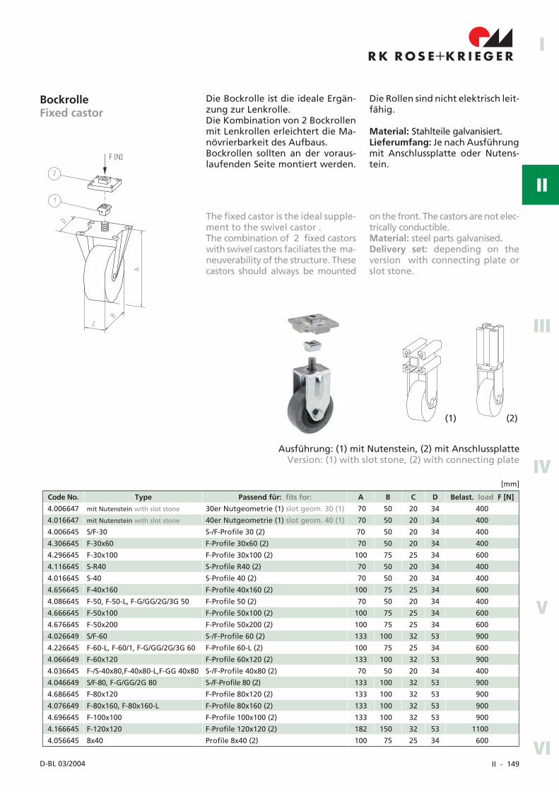
II - 149
I
II
IV
III
V
VID-BL 03/2004
BockrolleFixed castor
Die Bockrolle ist die ideale Ergän-zung zur Lenkrolle.Die Kombination von 2 Bockrollenmit Lenkrollen erleichtert die Ma-növrierbarkeit des Aufbaus.Bockrollen sollten an der voraus-laufenden Seite montiert werden.
Die Rollen sind nicht elektrisch leit-fähig.
Material: Stahlteile galvanisiert.Lieferumfang: Je nach Ausführungmit Anschlussplatte oder Nutens-tein.
Code No. Type Passend für: fits for: A B C D Belast. load F [N]
4.006647 mit Nutenstein with slot stone 30er Nutgeometrie (1) slot geom. 30 (1) 70 50 20 34 400
4.016647 mit Nutenstein with slot stone 40er Nutgeometrie (1) slot geom. 40 (1) 70 50 20 34 400
4.006645 S/F-30 S-/F-Profile 30 (2) 70 50 20 34 400
4.306645 F-30x60 F-Profile 30x60 (2) 70 50 20 34 400
4.296645 F-30x100 F-Profile 30x100 (2) 100 75 25 34 600
4.116645 S-R40 S-Profile R40 (2) 70 50 20 34 400
4.016645 S-40 S-Profile 40 (2) 70 50 20 34 400
4.656645 F-40x160 F-Profile 40x160 (2) 100 75 25 34 600
4.086645 F-50, F-50-L, F-G/GG/2G/3G 50 F-Profile 50 (2) 70 50 20 34 400
4.666645 F-50x100 F-Profile 50x100 (2) 100 75 25 34 600
4.676645 F-50x200 F-Profile 50x200 (2) 100 75 25 34 600
4.026649 S/F-60 S-/F-Profile 60 (2) 133 100 32 53 900
4.226645 F-60-L, F-60/1, F-G/GG/2G/3G 60 F-Profile 60-L (2) 100 75 25 34 600
4.066649 F-60x120 F-Profile 60x120 (2) 133 100 32 53 900
4.036645 F-/S-40x80,F-40x80-L,F-GG 40x80 S-/F-Profile 40x80 (2) 70 50 20 34 400
4.046649 S/F-80, F-G/GG/2G 80 S-/F-Profile 80 (2) 133 100 32 53 900
4.686645 F-80x120 F-Profile 80x120 (2) 133 100 32 53 900
4.076649 F-80x160, F-80x160-L F-Profile 80x160 (2) 133 100 32 53 900
4.696645 F-100x100 F-Profile 100x100 (2) 133 100 32 53 900
4.166645 F-120x120 F-Profile 120x120 (2) 182 150 32 53 1100
4.056645 8x40 Profile 8x40 (2) 100 75 25 34 600
[mm]
The fixed castor is the ideal supple-ment to the swivel castor .The combination of 2 fixed castorswith swivel castors faciliates the ma-neuverability of the structure. Thesecastors should always be mounted
on the front. The castors are not elec-trically conductible.Material: steel parts galvanisedDelivery set: depending on theversion with connecting plate orslot stone.
(1) (2)
Ausführung: (1) mit Nutenstein, (2) mit AnschlussplatteVersion: (1) with slot stone, (2) with connecting plate
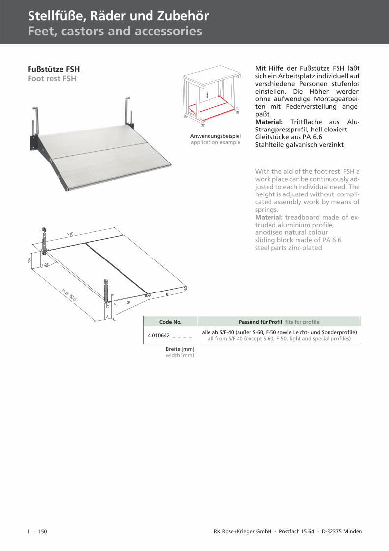
II - 150 RK Rose+Krieger GmbH � Postfach 15 64 � D-32375 Minden
Stellfüße, Räder und ZubehörFeet, castors and accessories
Fußstütze FSHFoot rest FSH
Mit Hilfe der Fußstütze FSH läßtsich ein Arbeitsplatz individuell aufverschiedene Personen stufenloseinstellen. Die Höhen werdenohne aufwendige Montagearbei-ten mit Federverstellung ange-paßt.Material: Trittfläche aus Alu-Strangpressprofil, hell eloxiertGleitstücke aus PA 6.6Stahlteile galvanisch verzinkt
Code No. Passend für Profil fits for profile
4.010642 _ _ _ _ alle ab S/F-40 (außer S-60, F-50 sowie Leicht- und Sonderprofile)all from S/F-40 (except S-60, F-50, light and special profiles)
Anwendungsbeispielapplication example
Breite [mm]width [mm]
With the aid of the foot rest FSH awork place can be continuously ad-justed to each individual need. Theheight is adjusted without compli-cated assembly work by means ofsprings.Material: treadboard made of ex-truded aluminium profile,anodised natural coloursliding block made of PA 6.6steel parts zinc-plated
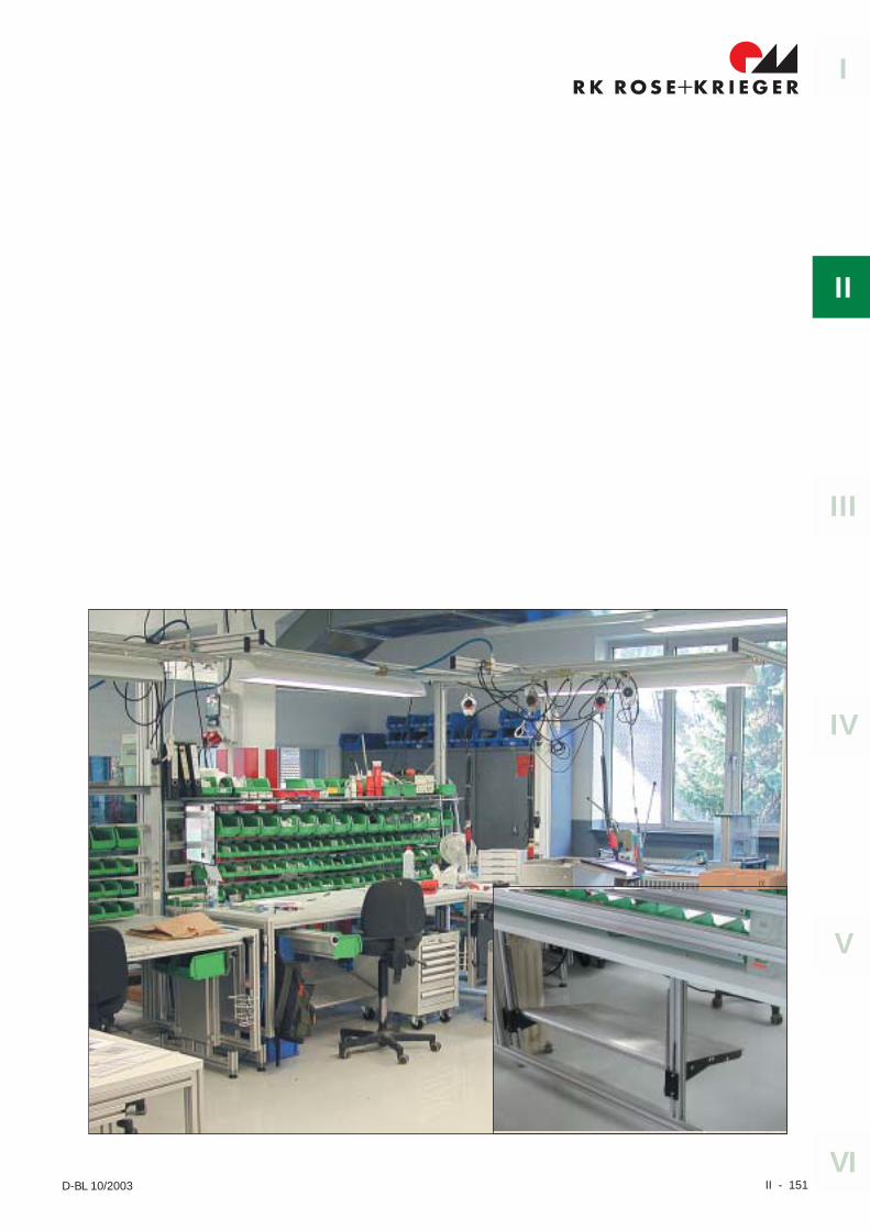
II - 151
I
II
IV
III
V
VID-BL 10/2003
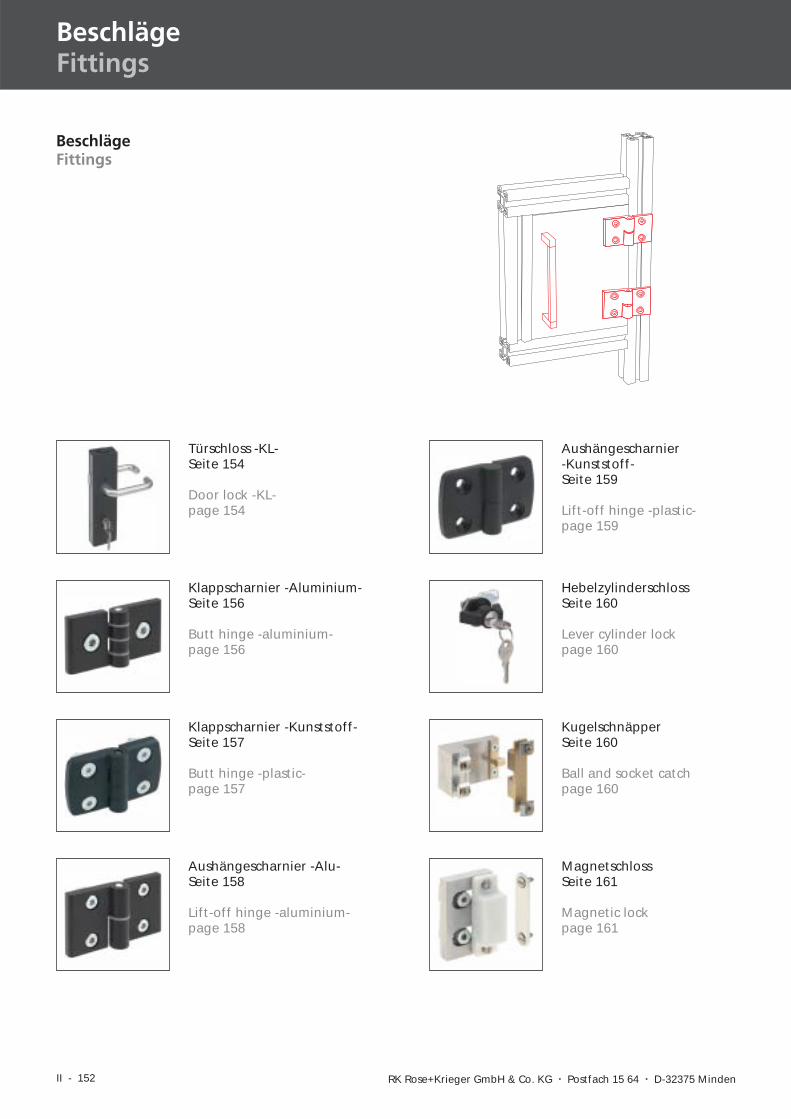
II - 152 RK Rose+Krieger GmbH & Co. KG � Postfach 15 64 � D-32375 Minden
BeschlägeFittings
BeschlägeFittings
Türschloss -KL-Seite 154
Door lock -KL-page 154
Klappscharnier -Aluminium-Seite 156
Butt hinge -aluminium-page 156
Klappscharnier -Kunststoff-Seite 157
Butt hinge -plastic-page 157
KugelschnäpperSeite 160
Ball and socket catchpage 160
HebelzylinderschlossSeite 160
Lever cylinder lockpage 160
Aushängescharnier -Alu-Seite 158
Lift-off hinge -aluminium-page 158
Aushängescharnier-Kunststoff-Seite 159
Lift-off hinge -plastic-page 159
MagnetschlossSeite 161
Magnetic lockpage 161
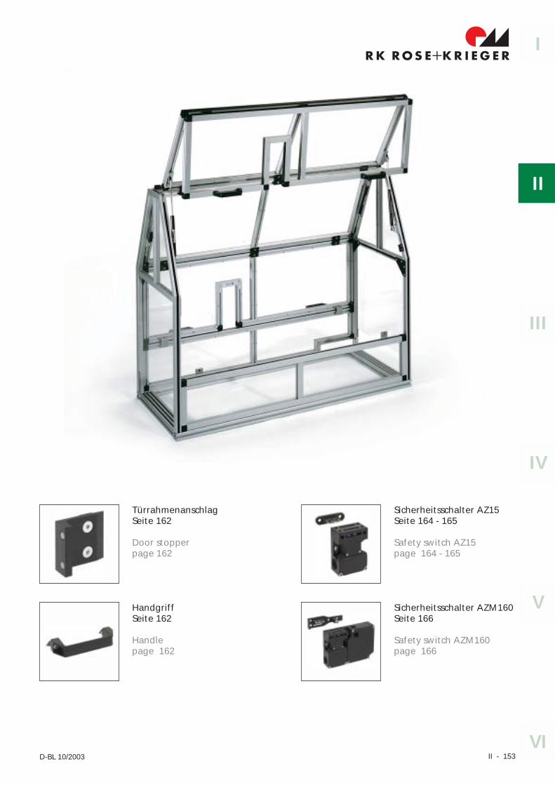
II - 153
I
II
IV
III
V
VID-BL 10/2003
TürrahmenanschlagSeite 162
Door stopperpage 162
HandgriffSeite 162
Handlepage 162
Sicherheitsschalter AZ15Seite 164 - 165
Safety switch AZ15page 164 - 165
Sicherheitsschalter AZM160Seite 166
Safety switch AZM160page 166
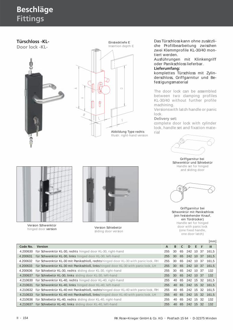
II - 154 RK Rose+Krieger GmbH & Co. KG � Postfach 15 64 � D-32375 Minden
BeschlägeFittings
Türschloss -KL-Door lock -KL-
Griffgarnitur beiSchwenktür und Schiebetür
Handle set for hingedand sliding door
Griffgarnitur beiSchwenktür mit Panikschloss
(ein feststehender Knauf,ein Türdrücker)
Handle set for hingeddoor with panic lock(one fixed handle,
one door latch)
Das Türschloss kann ohne zusätzli-che Profilbearbeitung zwischenzwei Klemmprofile KL-30/40 mon-tiert werden.Ausführungen mit Klinkengriffoder Panikschloss lieferbar.Lieferumfang:komplettes Türschloss mit Zylin-derschloss, Griffgarnitur und Be-festigungsmaterial
Code No. Version A B C D E F H
4.200630 für Schwenktür KL-30, rechts hinged door KL-30, right-hand 255 30 65 242 10 37 161,5
4.200631 für Schwenktür KL-30, links hinged door KL-30, left-hand 255 30 65 242 10 37 161,5
4.200632 für Schwenktür KL-30 mit Panikschloß, rechts hinged door KL-30 with panic lock, RH 255 30 65 242 10 37 161,5
4.200633 für Schwenktür KL-30 mit Panikschloß, links hinged door KL-30 with panic lock, LH 255 30 65 242 10 37 161,5
4.200636 für Schiebetür KL-30, rechts sliding door KL-30, right-hand 255 30 65 242 10 37 132
4.200637 für Schiebetür KL-30, links sliding door KL-30, left-hand 255 30 65 242 10 37 132
4.210630 für Schwenktür KL-40, rechts hinged door KL-40, right-hand 255 40 65 242 15 32 161,5
4.210631 für Schwenktür KL-40, links hinged door KL-40, left-hand 255 40 65 242 15 32 161,5
4.210632 für Schwenktür KL-40 mit Panikschloß, rechts hinged door KL-40 with panic lock, RH 255 40 65 242 15 32 161,5
4.210633 für Schwenktür KL-40 mit Panikschloß, links hinged door KL-40 with panic lock, LH 255 40 65 242 15 32 161,5
4.210636 für Schiebetür KL-40, rechts sliding door KL-40, right-hand 255 40 65 242 15 32 132
4.210637 für Schiebetür KL-40, links sliding door KL-40, left-hand 255 40 65 242 15 32 132
[mm]
The door lock can be assembledbetween two clamping profilesKL-30/40 without further profilemachining.Versions with latch handle or paniclock.Delivery set:complete door lock with cylinderlock, handle set and fixation mate-rialAbbildung Type rechts
Illustr. right-hand version
Einstecktiefe EInsertion depth E
Version Schwenktürhinged door version Version Schiebetür
sliding door version
II - 155
R K R OS E K R I EG E R+I
II
IV
III
V
VID-BL 09/2004
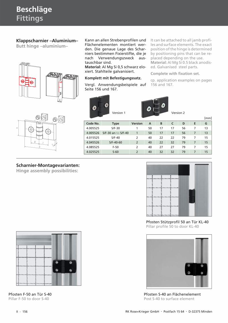
II - 156 RK Rose+Krieger GmbH � Postfach 15 64 � D-32375 Minden
BeschlägeFittings
Pfosten F-50 an Tür S-40Pillar F-50 to door S-40
Klappscharnier –Aluminium–Butt hinge –aluminium–
Kann an allen Strebenprofilen undFlächenelementen montiert wer-den. Die genaue Lage des Schar-niers bestimmen Fixierstifte, die jenach Verwendungszweck aus-tauschbar sind.Material: Al Mg Si 0,5 schwarz elo-xiert. Stahlteile galvanisiert.
Komplett mit Befestigungssatz.
Vergl. Anwendungsbeispiele aufSeite 156 und 167.
Code No. Type Version A B C D E G
4.005525 S/F-30 1 50 17 17 56 7 13
4.005526 S/F-30 an to S/F-40 1 50 17 17 56 7 13
4.015525 S/F-40 2 40 22 22 79 7 15
4.045526 S/F-40-60 2 40 22 32 79 7 15
4.085525 F-50 2 40 27 27 79 7 15
4.025525 S-60 2 40 32 32 79 7 15
[mm]
It can be attached to all jamb profi-les and surface elements. The exactposition of the hinge is determinedby positioning pins that can be re-placed depending on the use.Material: Al Mg Si 0.5 black anodis-ed. Galvanised steel parts.
Complete with fixation set.
cp. application examples on pages156 and 167.
Pfosten Stützprofil 50 an Tür KL-40Pillar profile 50 to door KL-40
Pfosten S-40 an FlächenelementPost S-40 to surface element
Scharnier-Montagevarianten:Hinge assembly possibilities:
Version 1 Version 2
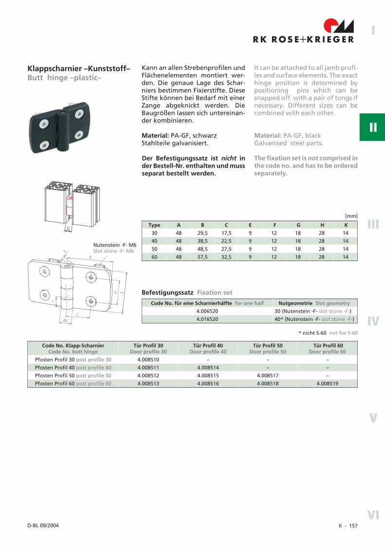
II - 157
R K R OS E K R I EG E R+I
II
IV
III
V
VID-BL 09/2004
The fixation set is not comprised inthe code no. and has to be orderedseparately.
It can be attached to all jamb profi-les and surface elements. The exacthinge position is determined bypositioning pins which can besnapped off with a pair of tongs ifnecessary. Different sizes can becombined with each other.
Material: PA-GF, blackGalvanised steel parts.
Befestigungssatz Fixation set
Der Befestigungssatz ist nicht inder Bestell-Nr. enthalten und mussseparat bestellt werden.
Code No. Klapp-ScharnierCode No. butt hinge
Tür Profil 30Door profile 30
Tür Profil 40Door profile 40
Tür Profil 50Door profile 50
Tür Profil 60Door profile 60
Pfosten Profil 30 post profile 30 4.008510 – – –
Pfosten Profil 40 post profile 40 4.008511 4.008514 – –
Pfosten Profil 50 post profile 50 4.008512 4.008515 4.008517 –
Pfosten Profil 60 post profile 60 4.008513 4.008516 4.008518 4.008519
Code No. für eine Scharnierhälfte for one half Nutgeometrie Slot geometry
4.006520 30 (Nutenstein -F- slot stone -F-)
4.016520 40* (Nutenstein -F- slot stone -F-)
Type A B C E F G H K
30 48 29,5 17,5 9 12 18 28 14
40 48 38,5 22,5 9 12 18 28 14
50 48 48,5 27,5 9 12 18 28 14
60 48 57,5 32,5 9 12 18 28 14
[mm]
Klappscharnier –Kunststoff–Butt hinge –plastic–
Kann an allen Strebenprofilen undFlächenelementen montiert wer-den. Die genaue Lage des Schar-niers bestimmen Fixierstifte. DieseStifte können bei Bedarf mit einerZange abgeknickt werden. DieBaugrößen lassen sich untereinan-der kombinieren.
Material: PA-GF, schwarzStahlteile galvanisiert.
Nutenstein -F- M6Slot stone -F- M6
* nicht S-60 not for S-60
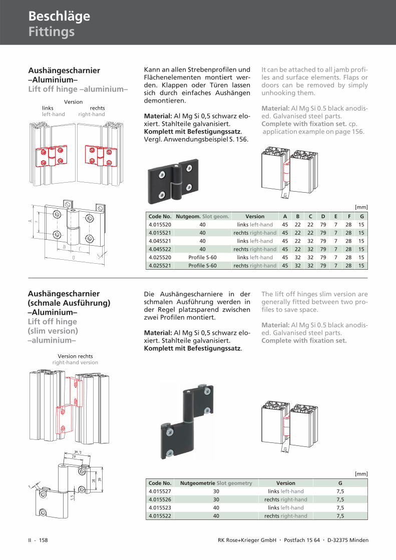
II - 158 RK Rose+Krieger GmbH � Postfach 15 64 � D-32375 Minden
BeschlägeFittings
Kann an allen Strebenprofilen undFlächenelementen montiert wer-den. Klappen oder Türen lassensich durch einfaches Aushängendemontieren.
Material: Al Mg Si 0,5 schwarz elo-xiert. Stahlteile galvanisiert.Komplett mit Befestigungssatz.Vergl. Anwendungsbeispiel S. 156.
Code No. Nutgeom. Slot geom. Version A B C D E F G
4.015520 40 links left-hand 45 22 22 79 7 28 15
4.015521 40 rechts right-hand 45 22 22 79 7 28 15
4.045521 40 links left-hand 45 22 32 79 7 28 15
4.045522 40 rechts right-hand 45 22 32 79 7 28 15
4.025520 Profile S-60 links left-hand 45 32 32 79 7 28 15
4.025521 Profile S-60 rechts right-hand 45 32 32 79 7 28 15
[mm]
Aushängescharnier–Aluminium–Lift off hinge –aluminium–
Versionlinks rechtsleft-hand right-hand
It can be attached to all jamb profi-les and surface elements. Flaps ordoors can be removed by simplyunhooking them.
Material: Al Mg Si 0.5 black anodis-ed. Galvanised steel parts.Complete with fixation set. cp.application example on page 156.
Aushängescharnier(schmale Ausführung)–Aluminium–Lift off hinge(slim version)–aluminium–
Version rechtsright-hand version
The lift off hinges slim version aregenerally fitted between two pro-files to save space.
Material: Al Mg Si 0.5 black anodis-ed. Galvanised steel parts.Complete with fixation set.
Code No. Nutgeometrie Slot geometry Version G
4.015527 30 links left-hand 7,5
4.015526 30 rechts right-hand 7,5
4.015523 40 links left-hand 7,5
4.015522 40 rechts right-hand 7,5
[mm]
Die Aushängescharniere in derschmalen Ausführung werden inder Regel platzsparend zwischenzwei Profilen montiert.
Material: Al Mg Si 0,5 schwarz elo-xiert. Stahlteile galvanisiert.Komplett mit Befestigungssatz.
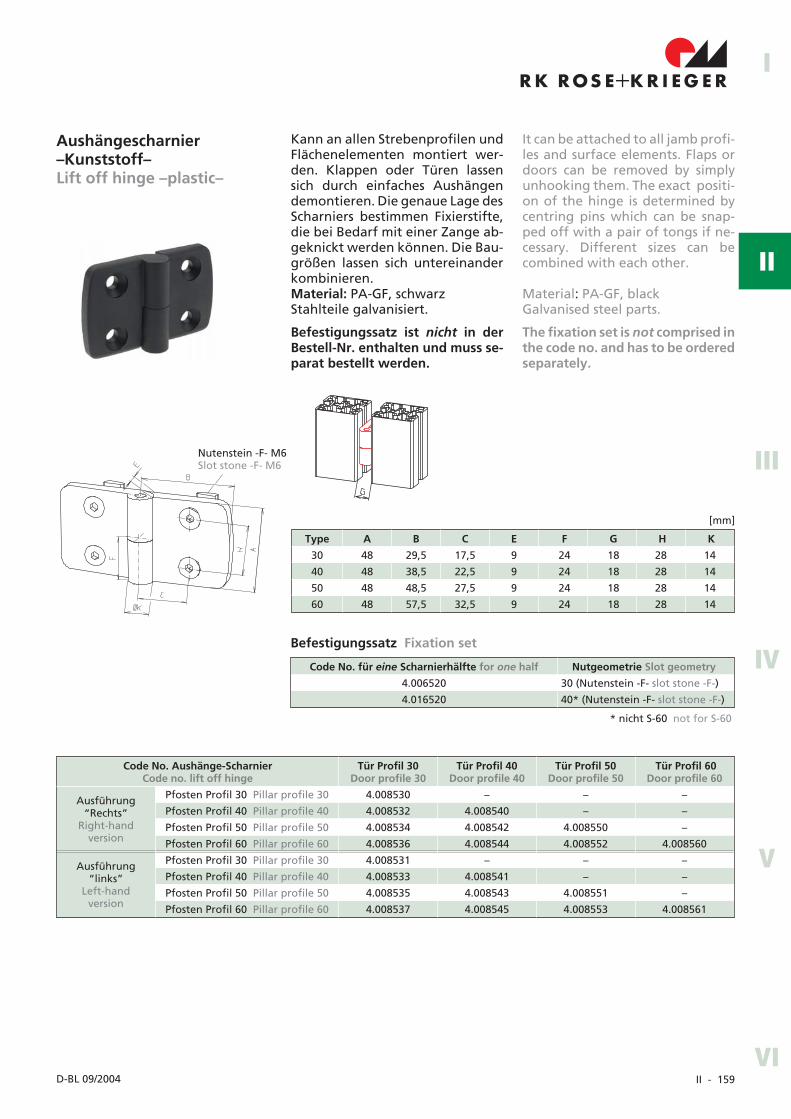
II - 159
R K R OS E K R I EG E R+I
II
IV
III
V
VID-BL 09/2004
Code No. für eine Scharnierhälfte for one half Nutgeometrie Slot geometry
4.006520 30 (Nutenstein -F- slot stone -F-)
4.016520 40* (Nutenstein -F- slot stone -F-)
Befestigungssatz Fixation set
Type A B C E F G H K
30 48 29,5 17,5 9 24 18 28 14
40 48 38,5 22,5 9 24 18 28 14
50 48 48,5 27,5 9 24 18 28 14
60 48 57,5 32,5 9 24 18 28 14
[mm]
Kann an allen Strebenprofilen undFlächenelementen montiert wer-den. Klappen oder Türen lassensich durch einfaches Aushängendemontieren. Die genaue Lage desScharniers bestimmen Fixierstifte,die bei Bedarf mit einer Zange ab-geknickt werden können. Die Bau-größen lassen sich untereinanderkombinieren.Material: PA-GF, schwarzStahlteile galvanisiert.
Befestigungssatz ist nicht in derBestell-Nr. enthalten und muss se-parat bestellt werden.
Aushängescharnier–Kunststoff–Lift off hinge –plastic–
It can be attached to all jamb profi-les and surface elements. Flaps ordoors can be removed by simplyunhooking them. The exact positi-on of the hinge is determined bycentring pins which can be snap-ped off with a pair of tongs if ne-cessary. Different sizes can becombined with each other.
Material: PA-GF, blackGalvanised steel parts.
The fixation set is not comprised inthe code no. and has to be orderedseparately.
* nicht S-60 not for S-60
Nutenstein -F- M6Slot stone -F- M6
Code No. Aushänge-ScharnierCode no. lift off hinge
Tür Profil 30Door profile 30
Tür Profil 40Door profile 40
Tür Profil 50Door profile 50
Tür Profil 60Door profile 60
Ausführung“Rechts”
Right-handversion
Pfosten Profil 30 Pillar profile 30 4.008530 – – –
Pfosten Profil 40 Pillar profile 40 4.008532 4.008540 – –
Pfosten Profil 50 Pillar profile 50 4.008534 4.008542 4.008550 –
Pfosten Profil 60 Pillar profile 60 4.008536 4.008544 4.008552 4.008560
Ausführung“links”
Left-handversion
Pfosten Profil 30 Pillar profile 30 4.008531 – – –
Pfosten Profil 40 Pillar profile 40 4.008533 4.008541 – –
Pfosten Profil 50 Pillar profile 50 4.008535 4.008543 4.008551 –
Pfosten Profil 60 Pillar profile 60 4.008537 4.008545 4.008553 4.008561
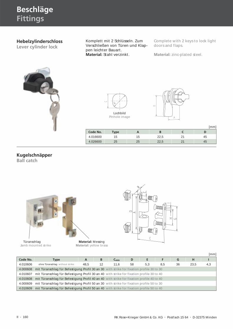
II - 160 RK Rose+Krieger GmbH & Co. KG � Postfach 15 64 � D-32375 Minden
BeschlägeFittings
HebelzylinderschlossLever cylinder lock
Komplett mit 2 Schlüsseln. ZumVerschließen von Türen und Klap-pen leichter Bauart.Material: Stahl verzinkt.
Code No. Type A B C D
4.016600 15 15 22,5 21 45
4.026600 25 25 22,5 21 45
[mm]
LochbildPinhole image
Complete with 2 keys to lock lightdoors and flaps.
Material: zinc-plated steel.
KugelschnäpperBall catch
Code No. Type A B Cmin D E F G H I
4.010606 ohne Türanschlag without strike 48,5 12 11,6 58 5,3 8,5 36 23,5 4,3
4.000608 mit Türanschlag für Befestigung Profil 30 an 30 with strike for fixation profile 30 to 30
4.010607 mit Türanschlag für Befestigung Profil 30 an 40 with strike for fixation profile 30 to 40
4.010608 mit Türanschlag für Befestigung Profil 40 an 40 with strike for fixation profile 40 to 40
4.000609 mit Türanschlag für Befestigung Profil 50 an 30 with strike for fixation profile 50 to 30
4.010609 mit Türanschlag für Befestigung Profil 50 an 40 with strike for fixation profile 50 to 40
[mm]
Türanschlag Material: MessingJamb mounted strike Material: yellow brass
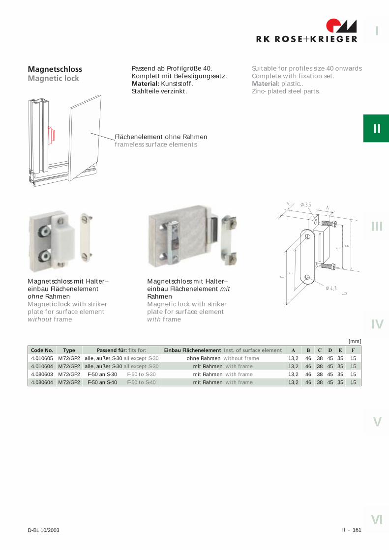
II - 161
I
II
IV
III
V
VID-BL 10/2003
MagnetschlossMagnetic lock
Passend ab Profilgröße 40.Komplett mit Befestigungssatz.Material: Kunststoff.Stahlteile verzinkt.
Code No. Type Passend für: fits for: Einbau Flächenelement Inst. of surface element A B C D E F
4.010605 M72/GP2 alle, außer S-30 all except S-30 ohne Rahmen without frame 13,2 46 38 45 35 15
4.010604 M72/GP2 alle, außer S-30 all except S-30 mit Rahmen with frame 13,2 46 38 45 35 15
4.080603 M72/GP2 F-50 an S-30 F-50 to S-30 mit Rahmen with frame 13,2 46 38 45 35 15
4.080604 M72/GP2 F-50 an S-40 F-50 to S-40 mit Rahmen with frame 13,2 46 38 45 35 15
[mm]
Suitable for profiles size 40 onwardsComplete with fixation set.Material: plastic..Zinc- plated steel parts.
Magnetschloss mit Halter–einbau Flächenelementohne RahmenMagnetic lock with strikerplate for surface elementwithout frame
Magnetschloss mit Halter–einbau Flächenelement mitRahmenMagnetic lock with strikerplate for surface elementwith frame
Flächenelement ohne Rahmenframeless surface elements
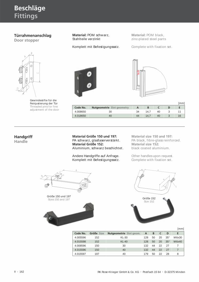
II - 162 RK Rose+Krieger GmbH & Co. KG � Postfach 15 64 � D-32375 Minden
BeschlägeFittings
TürrahmenanschlagDoor stopper
Material: POM schwarz,Stahlteile verzinkt
Komplett mit Befestigungssatz.
Code No. Nutgeometrie Slot geometry A B C D E
4.008650 30 34 14,7 40 3 11
4.018650 40 44 14,7 40 3 16
[mm]
HandgriffHandle
Material Größe 150 und 197:PA schwarz, glasfaserverstärkt.Material Größe 152:Aluminium, schwarz beschichtet.
Andere Handgriffe auf Anfrage.Komplett mit Befestigungssatz.
Code No. Größe Size Nutgeometrie Slot geom. A B C D E
4.005596 152 KL-30 128 50 20 35° M6x30
4.015598 152 KL-40 128 50 20 35° M6x40
4.008596 150 30 132 44 22 27 7
4.015596 150 40 132 44 22 27 7
4.015597 197 40 179 50 22 28 8
[mm]
Gewindestifte für dieFeinjustierung der TürThreaded pins for fineadjustment of the door
Material: POM black,zinc-plated steel parts
Complete with fixation set.
Material size 150 and 197:PA black, fibre-glass reinforced.Material size 152:black coated aluminium.
Other handles upon request.Complete with fixation set.
Größe 150 und 197Sizes 150 and 197 Größe 152
Size 152
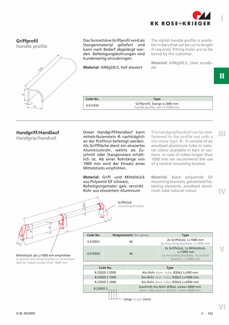
II - 163
R K R OS E K R I EG E R+I
II
IV
III
V
VID-BL 06/2004
GriffprofilHandle profile
Das formschöne Griffprofil wird alsStangenmaterial geliefert undkann nach Bedarf abgelängt wer-den. Befestigungsbohrungen sindkundenseitig einzubringen.
Material: AlMgSi0,5, hell eloxiert
The stylish handle profile is availa-ble in bars that can be cut to lengthif required. Fitting holes are to bebored by the customer.
Material: AlMgSi0,5, clear anodis-ed.
Code No. Type
4.015595 Griffprofil, Stange à 2000 mmhandle profile, bar of 2000 mm
Handgriff/HandlaufHandgrip/handrail
Dieser Handgriff/Handlauf kannmittels Nutenstein -R- nachträglichan der Profilnut befestigt werden.Als Grifffläche dient ein eloxiertesAluminiumrohr, welchs als Zu-schnitt oder Stangenware erhält-lich ist. Ab einer Rohrlänge von1000 mm wird der Einsatz einesMittelstücks empfohlen.
Material: Griff -und Mittelstückaus Polyamid GF schwarz,Befestigungsmater. galv. verzinktRohr aus eloxiertem Aluminium
This handgrip/handrail can be laterfastened to the profile nut with aslot stone type -R-. It consists of ananodised aluminium tube in natu-ral colour available in bars or sec-tions. In case of tubes longer than1000 mm we recommend the useof a central mounting bracket.
Material: black polyamide GFmounting brackets, galvanised fas-tening elements, anodised alumi-nium tube natural colour.
Code No. Nutgeometrie Slot geom. Type
4.018501 40 2x Griffstück, L<1000 mm2x mounting brackets, L<1000 mm
4.018502 40
2x Griffstück, 1x Mittelstück,L>1000 mm
2x mounting brackets, 1x centralbracket, L>1000 mm
Code No. Type
8.23020 2 0500 Alu-Rohr alum. tube, Ø30x2 L=500 mm
8.23020 2 1000 Alu-Rohr alum. tube, Ø30x2 L=1000 mm
8.23020 2 2000 Alu-Rohr alum. tube, Ø30x2 L=2000 mm
8.23020 2 _ _ _ _ Zuschnitt Alu-Rohr Ø30x2, Lmax= 6000 mmalum. tube section Ø30x2, Lmax= 6000 mm
Länge length [mm]
Mittelstück ab L>1000 mm empfohlena central mounting bracket is recommen-ded for tubes longer than 1000 mm
Griffstückmounting bracket
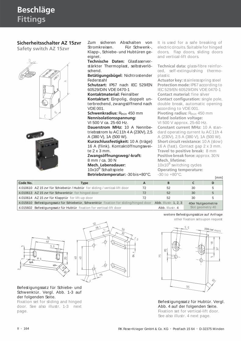
II - 164 RK Rose+Krieger GmbH & Co. KG � Postfach 15 64 � D-32375 Minden
BeschlägeFittings
Sicherheitsschalter AZ 15zvrSafety switch AZ 15zvr
Zum sicheren Abschalten vonStromkreisen. Für Schwenk-,Klapp-, Schiebe- und Hubtüren ge-eignet.Technische Daten: Glasfaserver-stärkter Thermoplast, selbstverlö-schend.Betätigungsbügel: NichtrostenderFederstahlSchutzart: IP67 nach IEC 529/EN60529/DIN VDE 0470-1Kontaktmaterial: FeinsilberKontaktart: Einpolig, doppelt un-terbrechend, zwangsöffnend nachVDE 001.Schwenkradius: Rmin 450 mmNennisolationsspannung:VI 500 V ca. 25-60 Hz.Dauerstrom MHz: 10 A Nennbe-triebsstrom Iu AC 11h 4 A (230V), 2,5A (380 V), 1A (500 W).Kurzschlussfestigkeit: 10 A (träge)16 A (flink). Kontaktöffnungswei-te 2 x 3 mm.Zwangsöffnungsweg/-kraft:8 mm / ca. 30 NMech. Lebensdauer:10x106 SchaltspieleBetriebstemperatur: -30 bis +80°C.
Code No. Type A B C D
4.010610 AZ 15 zvr für Schiebetür / Hubtür for sliding / vertical-lift door 72 52 30 5
4.010613 AZ 15 zvr für Schwenktür for hinged door 72 52 30 5
4.010614 AZ 15 zvr für Klapptür for lift-up door 72 52 30 5
4.015610 Befestigungssatz für Schiebetür, Schwenktür fixation for sliding/hinged door Abb. Illustr. 1, 2, 3 40er NutgeometrieSlot geometry 404.015602 Befestigungssatz für Hubtür fixation for vertical-lift door Abb. Illustr. 4
Befestigungssatz für Schiebe- undSchwenktür. Vergl. Abb. 1-3 aufder folgenden Seite.Fixation set for sliding and hingeddoor. See also illustr. 1-3 nextpage.
Befestigungssatz für Hubtür. Vergl.Abb. 4 auf der folgenden Seite.Fixation set for vertical-lift door.See also illustr. 4 next page.
It is used for a safe breaking ofelectric circuits. Suitable for hingeddoors, flap doors, sliding doorsand vertical-lift doors.
Technical data: glass-fibre reinfor-ced, self-extinguishing thermo-plasticActuator key: stainless spring steelProtection mode: IP67 according toIEC 529/EN 60529/DIN VDE 0470-1Contact material: fine silverContact configuration: single pole,double break, automatic openingaccording to VDE 001.Pivoting radius: Rmin 450 mmRated isolation voltage:VI 500 V approx. 25-60 Hz.Constant current MHz: 10 A stan-dard operating current Iu AC 11h 4A (230V), 2.5 A (380 V), 1A (500 W).Short circuit resistance: 10 A (slow)16 A (fast). Contact gap 2 x 3 mm.Travel to positive break: 8 mmPositive break force: approx. 30 NMech. lifetime:10x106 switching cyclesOperating temperature:-30 to +80°C.
10/6 tief depth
weitere Befestigungssätze auf Anfrageother fixation sets upon request
[mm]
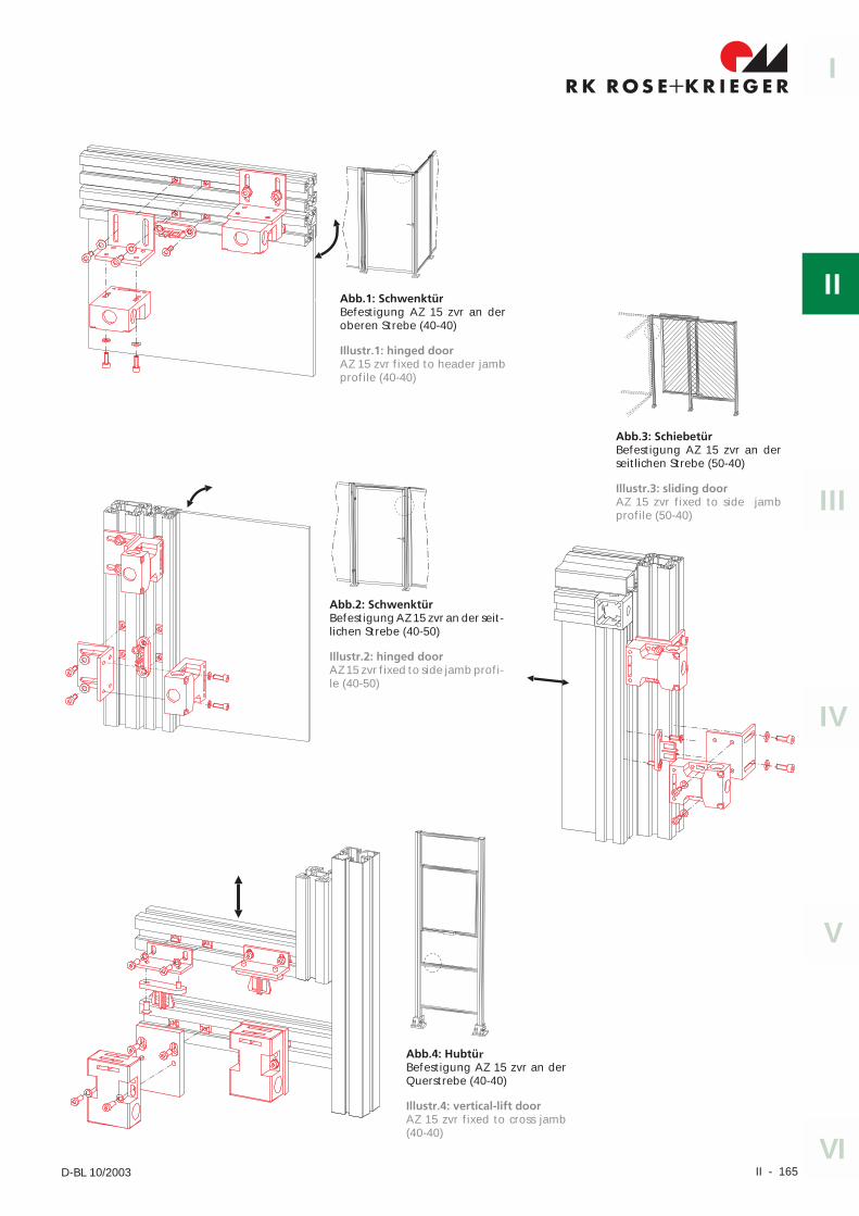
II - 165
I
II
IV
III
V
VID-BL 10/2003
Abb.4: Hubtür
Befestigung AZ 15 zvr an derQuerstrebe (40-40)
Abb.1: SchwenktürBefestigung AZ 15 zvr an deroberen Strebe (40-40)
Abb.2: SchwenktürBefestigung AZ 15 zvr an der seit-lichen Strebe (40-50)
Abb.3: SchiebetürBefestigung AZ 15 zvr an derseitlichen Strebe (50-40)
Illustr.1: hinged doorAZ 15 zvr fixed to header jambprofile (40-40)
Illustr.2: hinged doorAZ 15 zvr fixed to side jamb profi-le (40-50)
Illustr.3: sliding doorAZ 15 zvr fixed to side jambprofile (50-40)
Illustr.4: vertical-lift doorAZ 15 zvr fixed to cross jamb(40-40)
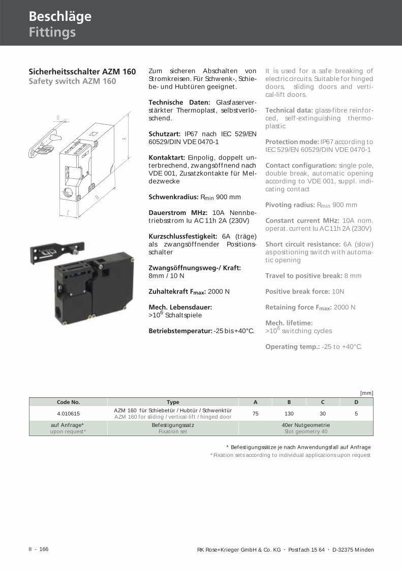
II - 166 RK Rose+Krieger GmbH & Co. KG � Postfach 15 64 � D-32375 Minden
BeschlägeFittings
Sicherheitsschalter AZM 160Safety switch AZM 160
Zum sicheren Abschalten vonStromkreisen. Für Schwenk-, Schie-be- und Hubtüren geeignet.
Technische Daten: Glasfaserver-stärkter Thermoplast, selbstverlö-schend.
Schutzart: IP67 nach IEC 529/EN60529/DIN VDE 0470-1
Kontaktart: Einpolig, doppelt un-terbrechend, zwangsöffnend nachVDE 001, Zusatzkontakte für Mel-dezwecke
Schwenkradius: Rmin 900 mm
Dauerstrom MHz: 10A Nennbe-triebsstrom Iu AC 11h 2A (230V)
Kurzschlussfestigkeit: 6A (träge)als zwangsöffnender Positions-schalter
Zwangsöffnungsweg-/ Kraft:8mm / 10 N
Zuhaltekraft Fmax: 2000 N
Mech. Lebensdauer:>106 Schaltspiele
Betriebstemperatur: -25 bis +40°C.
Code No. Type A B C D
4.010615 AZM 160 für Schiebetür / Hubtür / SchwenktürAZM 160 for sliding / vertical-lift / hinged door 75 130 30 5
auf Anfrage*upon request*
BefestigungssatzFixation set
40er NutgeometrieSlot geometry 40
[mm]
* Befestigungssätze je nach Anwendungsfall auf Anfrage*Fixation sets according to individual applications upon request
It is used for a safe breaking ofelectric circuits. Suitable for hingeddoors, sliding doors and verti-cal-lift doors.
Technical data: glass-fibre reinfor-ced, self-extinguishing thermo-plastic
Protection mode: IP67 according toIEC 529/EN 60529/DIN VDE 0470-1
Contact configuration: single pole,double break, automatic openingaccording to VDE 001, suppl. indi-cating contact
Pivoting radius: Rmin 900 mm
Constant current MHz: 10A nom.operat. current Iu AC 11h 2A (230V)
Short circuit resistance: 6A (slow)as positioning switch with automa-tic opening
Travel to positive break: 8 mm
Positive break force: 10N
Retaining force Fmax: 2000 N
Mech. lifetime:>106 switching cycles
Operating temp.: -25 to +40°C.
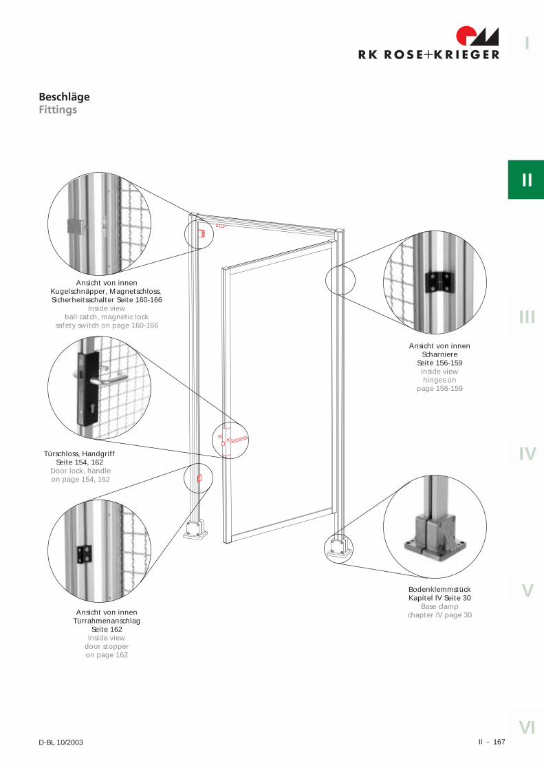
II - 167
I
II
IV
III
V
VID-BL 10/2003
BeschlägeFittings
Ansicht von innenKugelschnäpper, Magnetschloss,Sicherheitsschalter Seite 160-166
Inside viewball catch, magnetic lock
safety switch on page 160-166
Türschloss, HandgriffSeite 154, 162
Door lock, handleon page 154, 162
Ansicht von innenTürrahmenanschlag
Seite 162Inside view
door stopperon page 162
Ansicht von innenScharniere
Seite 156-159Inside viewhinges on
page 156-159
BodenklemmstückKapitel IV Seite 30
Base clampchapter IV page 30
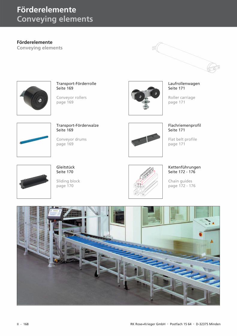
II - 168 RK Rose+Krieger GmbH � Postfach 15 64 � D-32375 Minden
FörderelementeConveying elements
Transport-FörderrolleSeite 169
Conveyor rollerspage 169
Transport-FörderwalzeSeite 169
Conveyor drumspage 169
GleitstückSeite 170
Sliding blockpage 170
LaufrollenwagenSeite 171
Roller carriagepage 171
FlachriemenprofilSeite 171
Flat belt profilepage 171
FörderelementeConveying elements
KettenführungenSeite 172 - 176
Chain guidespage 172 - 176
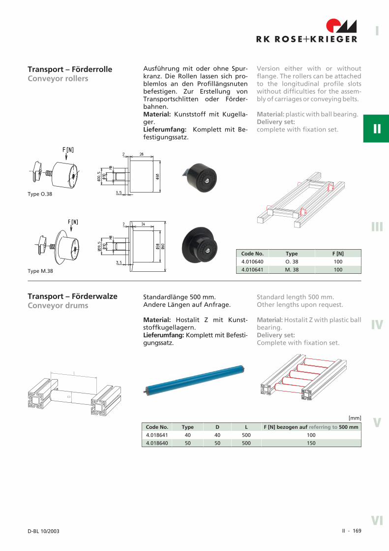
II - 169
I
II
IV
III
V
VID-BL 10/2003
Transport – FörderrolleConveyor rollers
Ausführung mit oder ohne Spur-kranz. Die Rollen lassen sich pro-blemlos an den Profillängsnutenbefestigen. Zur Erstellung vonTransportschlitten oder Förder-bahnen.Material: Kunststoff mit Kugella-ger.Lieferumfang: Komplett mit Be-festigungssatz.
Code No. Type F [N]
4.010640 O. 38 100
4.010641 M. 38 100
Transport – FörderwalzeConveyor drums
Standardlänge 500 mm.Andere Längen auf Anfrage.
Material: Hostalit Z mit Kunst-stoffkugellagern.Lieferumfang: Komplett mit Befesti-gungssatz.
Code No. Type D L F [N] bezogen auf referring to 500 mm
4.018641 40 40 500 100
4.018640 50 50 500 150
[mm]
Version either with or withoutflange. The rollers can be attachedto the longitudinal profile slotswithout difficulties for the assem-bly of carriages or conveying belts.
Material: plastic with ball bearing.Delivery set:complete with fixation set.
Standard length 500 mm.Other lengths upon request.
Material: Hostalit Z with plastic ballbearing.Delivery set:Complete with fixation set.
Type O.38
Type M.38
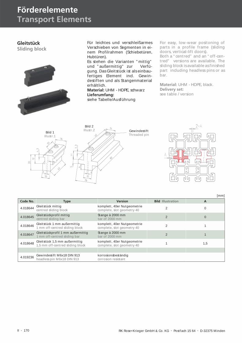
II - 170 RK Rose+Krieger GmbH & Co. KG � Postfach 15 64 � D-32375 Minden
FörderelementeTransport Elements
GleitstückSliding block
Code No. Type Version Bild Illustration A
4.018644 Gleitstück mittigcentred sliding block
komplett, 40er Nutgeometriecomplete, slot geometry 40 2 0
4.018645 Gleitstückprofil mittigcentred sliding bar
Stange à 2000 mmbar of 2000 mm 2 0
4.018646 Gleitstück 1 mm außermittig1 mm off-centred sliding block
komplett, 40er Nutgeometriecomplete, slot geometry 40 2 1
4.018647 Gleitstückprofil 1 mm außermittig1 mm off-centred sliding bar
Stange à 2000 mmbar of 2000 mm 2 1
4.018648 Gleitstück 1,5 mm außermittig1,5 mm off-centred sliding block
komplett, 40er Nutgeometriecomplete, slot geometry 40 1 1,5
4.019236 Gewindestift M6x18 DIN 913headless pin M6x18 DIN 913
korrosionsbeständigcorrosion resistant
[mm]
GewindestiftThreaded pin
Bild 1Illustr.1
Bild 2Illustr.2
For easy, low-wear positoning ofparts in a profile frame (slidingdoors, vertical-lift doors).Both a “centred” and an “off-cen-tred” versions are available. Thesliding block is available as finishedpart including headless pins or asbar.
Material: UHM - HDPE, black.Delivery set:see table / version
Für leichtes und verschleißarmesVerschieben von Segmenten in ei-nem Profilrahmen (Schiebetüren,Hubtüren).Es stehen die Varianten ”mittig”und ”außermittig” zur Verfü-gung. Das Gleitstück ist als einbau-fertiges Element incl. Gewin-destiften und als Stangenmaterialerhältlich.Material: UHM - HDPE, schwarzLieferumfang:siehe Tabelle/Ausführung
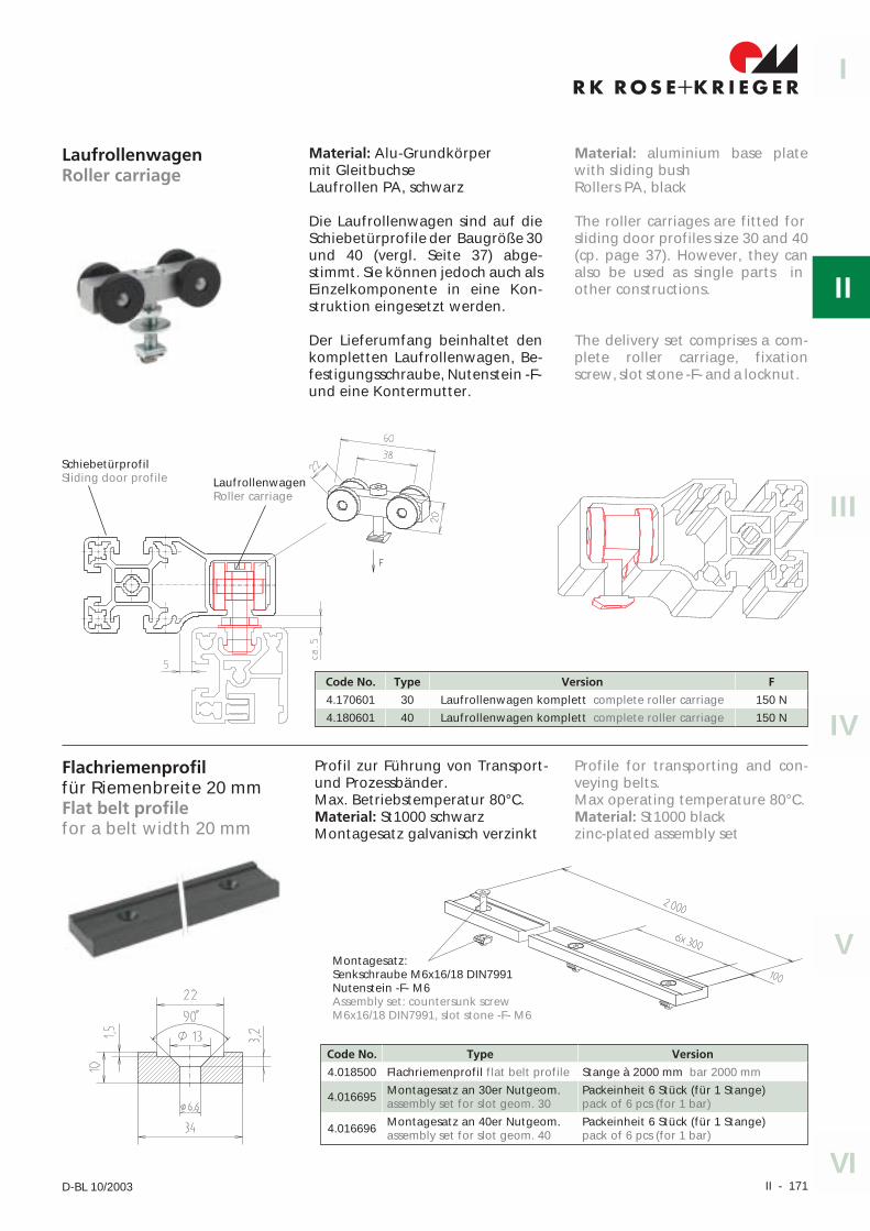
II - 171
I
II
IV
III
V
VID-BL 10/2003
Flachriemenprofilfür Riemenbreite 20 mmFlat belt profilefor a belt width 20 mm
Profil zur Führung von Transport-und Prozessbänder.Max. Betriebstemperatur 80°C.Material: St1000 schwarzMontagesatz galvanisch verzinkt
Code No. Type Version
4.018500 Flachriemenprofil flat belt profile Stange à 2000 mm bar 2000 mm
4.016695 Montagesatz an 30er Nutgeom.assembly set for slot geom. 30
Packeinheit 6 Stück (für 1 Stange)pack of 6 pcs (for 1 bar)
4.016696 Montagesatz an 40er Nutgeom.assembly set for slot geom. 40
Packeinheit 6 Stück (für 1 Stange)pack of 6 pcs (for 1 bar)
Profile for transporting and con-veying belts.Max operating temperature 80°C.Material: St1000 blackzinc-plated assembly set
LaufrollenwagenRoller carriage
Material: Alu-Grundkörpermit GleitbuchseLaufrollen PA, schwarz
Die Laufrollenwagen sind auf dieSchiebetürprofile der Baugröße 30und 40 (vergl. Seite 37) abge-stimmt. Sie können jedoch auch alsEinzelkomponente in eine Kon-struktion eingesetzt werden.
Der Lieferumfang beinhaltet denkompletten Laufrollenwagen, Be-festigungsschraube, Nutenstein -F-und eine Kontermutter.
Code No. Type Version F
4.170601 30 Laufrollenwagen komplett complete roller carriage 150 N
4.180601 40 Laufrollenwagen komplett complete roller carriage 150 N
SchiebetürprofilSliding door profile Laufrollenwagen
Roller carriage
Material: aluminium base platewith sliding bushRollers PA, black
The roller carriages are fitted forsliding door profiles size 30 and 40(cp. page 37). However, they canalso be used as single parts inother constructions.
The delivery set comprises a com-plete roller carriage, fixationscrew, slot stone -F- and a locknut.
Montagesatz:Senkschraube M6x16/18 DIN7991Nutenstein -F- M6Assembly set: countersunk screwM6x16/18 DIN7991, slot stone -F- M6
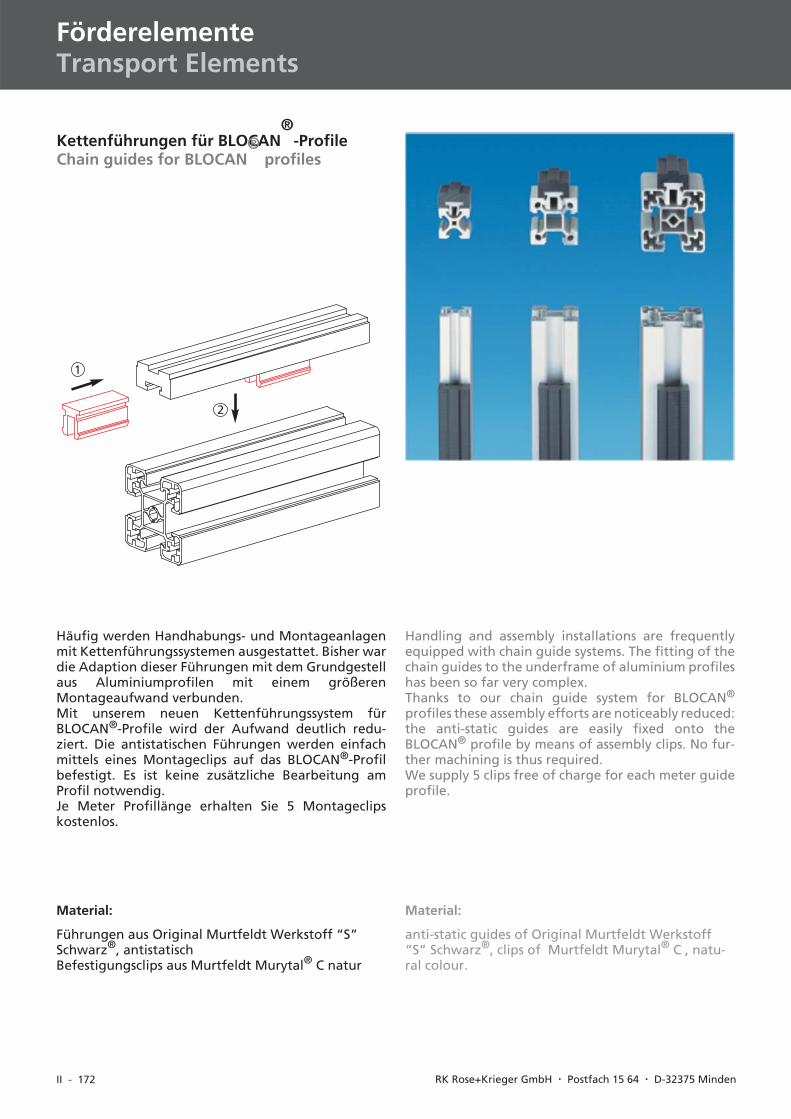
II - 172 RK Rose+Krieger GmbH � Postfach 15 64 � D-32375 Minden
FörderelementeTransport Elements
Kettenführungen für BLOCAN®
-ProfileChain guides for BLOCAN
®profiles
Häufig werden Handhabungs- und Montageanlagenmit Kettenführungssystemen ausgestattet. Bisher wardie Adaption dieser Führungen mit dem Grundgestellaus Aluminiumprofilen mit einem größerenMontageaufwand verbunden.Mit unserem neuen Kettenführungssystem fürBLOCAN®-Profile wird der Aufwand deutlich redu-ziert. Die antistatischen Führungen werden einfachmittels eines Montageclips auf das BLOCAN®-Profilbefestigt. Es ist keine zusätzliche Bearbeitung amProfil notwendig.Je Meter Profillänge erhalten Sie 5 Montageclipskostenlos.
Material:
Führungen aus Original Murtfeldt Werkstoff “S”Schwarz®, antistatischBefestigungsclips aus Murtfeldt Murytal® C natur
Handling and assembly installations are frequentlyequipped with chain guide systems. The fitting of thechain guides to the underframe of aluminium profileshas been so far very complex.Thanks to our chain guide system for BLOCAN®
profiles these assembly efforts are noticeably reduced:the anti-static guides are easily fixed onto theBLOCAN® profile by means of assembly clips. No fur-ther machining is thus required.We supply 5 clips free of charge for each meter guideprofile.
Material:
anti-static guides of Original Murtfeldt Werkstoff“S” Schwarz®, clips of Murtfeldt Murytal® C , natu-ral colour.
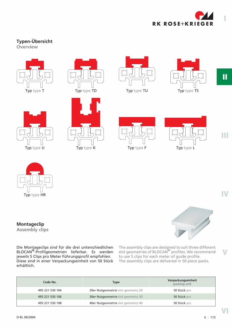
II - 173
R K R OS E K R I EG E R+I
II
IV
III
V
VID-BL 06/2004
Typen-ÜbersichtOverview
Typ type T Typ type TD Typ type TU Typ type TS
Typ type U Typ type K Typ type F Typ type L
Typ type HR
MontageclipAssembly clips
Die Montageclips sind für die drei unterschiedlichenBLOCAN®-Profilgeometrien lieferbar. Es werdenjeweils 5 Clips pro Meter Führungsprofil empfohlen.Diese sind in einer Verpackungseinheit von 50 Stückerhältlich.
The assembly clips are designed to suit three differentslot geometries of BLOCAN® profiles. We recommendto use 5 clips for each meter of guide profile.The assembly clips are delivered in 50 piece packs.
Code No. Type Verpackungseinheitpacking unit
495 221 530 104 20er Nutgeometrie slot geometry 20 50 Stück pcs
495 221 530 106 30er Nutgeometrie slot geometry 30 50 Stück pcs
495 221 530 108 40er Nutgeometrie slot geometry 40 50 Stück pcs
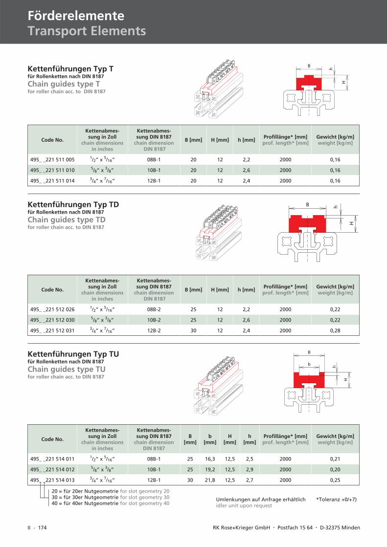
II - 174 RK Rose+Krieger GmbH � Postfach 15 64 � D-32375 Minden
Kettenführungen Typ Tfür Rollenketten nach DIN 8187
Chain guides type Tfor roller chain acc. to DIN 8187
B
H
h
Code No.
Kettenabmes-sung in Zoll
chain dimensionsin inches
Kettenabmes-sung DIN 8187
chain dimensionDIN 8187
B [mm] H [mm] h [mm] Profillänge* [mm]prof. length* [mm]
Gewicht [kg/m]weight [kg/m]
495_ _221 511 005 1/2” x 5/16” 08B-1 20 12 2,2 2000 0,16
495_ _221 511 010 5/8” x 3/8” 10B-1 20 12 2,6 2000 0,16
495_ _221 511 014 3/4” x 7/16” 12B-1 20 12 2,4 2000 0,16
Code No.
Kettenabmes-sung in Zoll
chain dimensionsin inches
Kettenabmes-sung DIN 8187
chain dimensionDIN 8187
B [mm] H [mm] h [mm] Profillänge* [mm]prof. length* [mm]
Gewicht [kg/m]weight [kg/m]
495_ _221 512 026 1/2” x 5/16” 08B-2 25 12 2,2 2000 0,22
495_ _221 512 030 5/8” x 3/8” 10B-2 25 12 2,6 2000 0,22
495_ _221 512 031 3/4” x 7/16” 12B-2 30 12 2,4 2000 0,28
B
H
hKettenführungen Typ TDfür Rollenketten nach DIN 8187
Chain guides type TDfor roller chain acc. to DIN 8187
Code No.
Kettenabmes-sung in Zoll
chain dimensionsin inches
Kettenabmes-sung DIN 8187
chain dimensionDIN 8187
B[mm]
b[mm]
H[mm]
h[mm]
Profillänge* [mm]prof. length* [mm]
Gewicht [kg/m]weight [kg/m]
495_ _221 514 011 1/2” x 5/16” 08B-1 25 16,3 12,5 2,5 2000 0,21
495_ _221 514 012 5/8” x 3/8” 10B-1 25 19,2 12,5 2,9 2000 0,20
495_ _221 514 013 3/4” x 7/16” 12B-1 30 21,8 12,5 2,7 2000 0,25
b
B
H
h
Kettenführungen Typ TUfür Rollenketten nach DIN 8187
Chain guides type TUfor roller chain acc. to DIN 8187
20 = für 20er Nutgeometrie for slot geometry 2030 = für 30er Nutgeometrie for slot geometry 3040 = für 40er Nutgeometrie for slot geometry 40
FörderelementeTransport Elements
*Toleranz +0/+7)Umlenkungen auf Anfrage erhältlichidler unit upon request
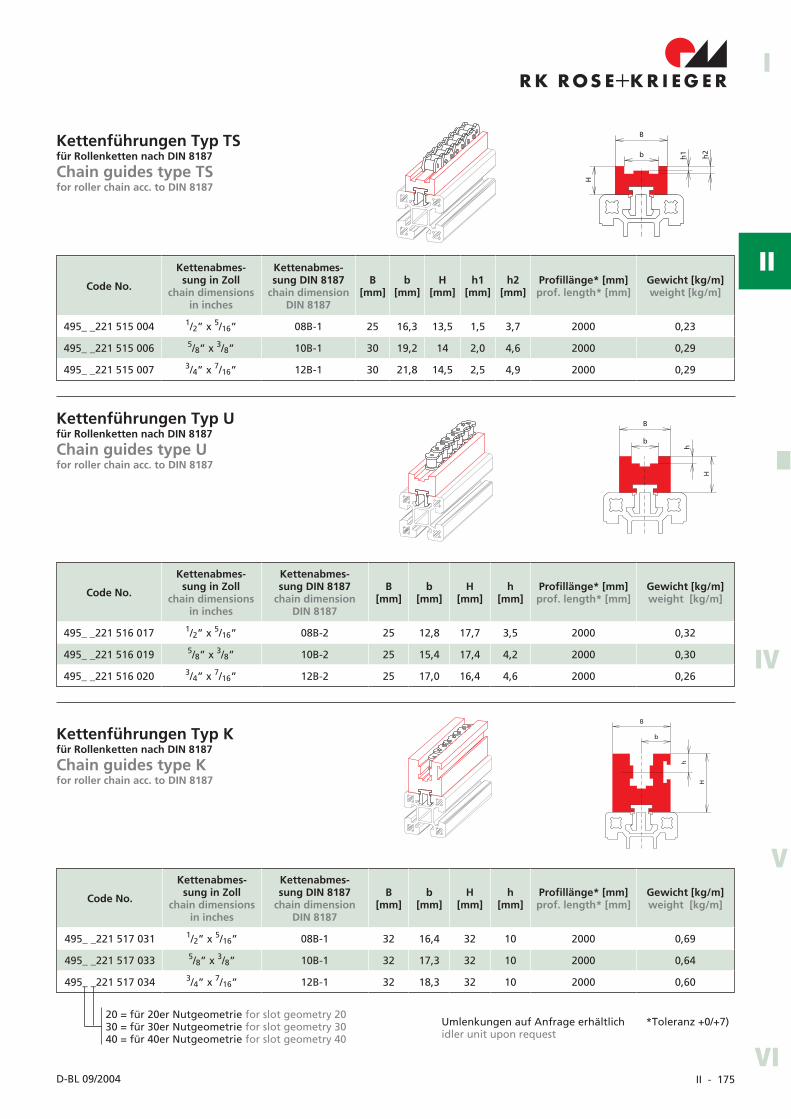
II - 175
R K R OS E K R I EG E R+I
II
IV
III
V
VID-BL 09/2004
b
B
h1 h2
H
b
B
h
H
b
B
h
H
Kettenführungen Typ TSfür Rollenketten nach DIN 8187
Chain guides type TSfor roller chain acc. to DIN 8187
Code No.
Kettenabmes-sung in Zoll
chain dimensionsin inches
Kettenabmes-sung DIN 8187
chain dimensionDIN 8187
B[mm]
b[mm]
H[mm]
h1[mm]
h2[mm]
Profillänge* [mm]prof. length* [mm]
Gewicht [kg/m]weight [kg/m]
495_ _221 515 004 1/2” x 5/16” 08B-1 25 16,3 13,5 1,5 3,7 2000 0,23
495_ _221 515 006 5/8” x 3/8” 10B-1 30 19,2 14 2,0 4,6 2000 0,29
495_ _221 515 007 3/4” x 7/16” 12B-1 30 21,8 14,5 2,5 4,9 2000 0,29
Code No.
Kettenabmes-sung in Zoll
chain dimensionsin inches
Kettenabmes-sung DIN 8187
chain dimensionDIN 8187
B[mm]
b[mm]
H[mm]
h[mm]
Profillänge* [mm]prof. length* [mm]
Gewicht [kg/m]weight [kg/m]
495_ _221 516 017 1/2” x 5/16” 08B-2 25 12,8 17,7 3,5 2000 0,32
495_ _221 516 019 5/8” x 3/8” 10B-2 25 15,4 17,4 4,2 2000 0,30
495_ _221 516 020 3/4” x 7/16” 12B-2 25 17,0 16,4 4,6 2000 0,26
Kettenführungen Typ Ufür Rollenketten nach DIN 8187
Chain guides type Ufor roller chain acc. to DIN 8187
Code No.
Kettenabmes-sung in Zoll
chain dimensionsin inches
Kettenabmes-sung DIN 8187
chain dimensionDIN 8187
B[mm]
b[mm]
H[mm]
h[mm]
Profillänge* [mm]prof. length* [mm]
Gewicht [kg/m]weight [kg/m]
495_ _221 517 031 1/2” x 5/16” 08B-1 32 16,4 32 10 2000 0,69
495_ _221 517 033 5/8” x 3/8” 10B-1 32 17,3 32 10 2000 0,64
495_ _221 517 034 3/4” x 7/16” 12B-1 32 18,3 32 10 2000 0,60
Kettenführungen Typ Kfür Rollenketten nach DIN 8187
Chain guides type Kfor roller chain acc. to DIN 8187
*Toleranz +0/+7)Umlenkungen auf Anfrage erhältlichidler unit upon request
20 = für 20er Nutgeometrie for slot geometry 2030 = für 30er Nutgeometrie for slot geometry 3040 = für 40er Nutgeometrie for slot geometry 40
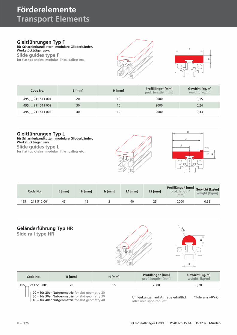
II - 176 RK Rose+Krieger GmbH � Postfach 15 64 � D-32375 Minden
Gleitführungen Typ Ffür Scharnierbandketten, modulare Gliederbänder,Werkstückträger usw.
Slide guides type Ffor flat top chains, modular links, pallets etc.
Code No. B [mm] H [mm] Profillänge* [mm]prof. length* [mm]
Gewicht [kg/m]weight [kg/m]
495_ _ 211 511 001 20 10 2000 0,15
495_ _ 211 511 002 30 10 2000 0,24
495_ _ 211 511 003 40 10 2000 0,33
Code No. B [mm] H [mm] h [mm] L1 [mm] L2 [mm]Profillänge* [mm]
prof. length*[mm]
Gewicht [kg/m]weight [kg/m]
495_ _ 211 512 001 45 12 2 40 25 2000 0,39
Gleitführungen Typ Lfür Scharnierbandketten, modulare Gliederbänder,Werkstückträger usw.
Slide guides type Lfor flat top chains, modular links, pallets etc.
Code No. B [mm] H [mm] Profillänge* [mm]prof. length* [mm]
Gewicht [kg/m]weight [kg/m]
495_ _ 211 513 001 20 15 2000 0,20
Geländerführung Typ HRSide rail type HR
B
H
B
L1
L2
h
H
B
H
R10
20 = für 20er Nutgeometrie for slot geometry 2030 = für 30er Nutgeometrie for slot geometry 3040 = für 40er Nutgeometrie for slot geometry 40
*Toleranz +0/+7)Umlenkungen auf Anfrage erhältlichidler unit upon request
FörderelementeTransport Elements
II - 177
R K R OS E K R I EG E R+I
II
IV
III
V
VID-BL 06/2004
II - 178 RK Rose+Krieger GmbH � Postfach 15 64 � D-32375 Minden
PneumatikPneumatic
PneumatikPneumatic
Pneumatik-AnschlussplatteSeite 179
Pneumatic-connecting platepage 179
Pneumatik-AnschlussSeite 179
Pneumatic-connectionpage 179
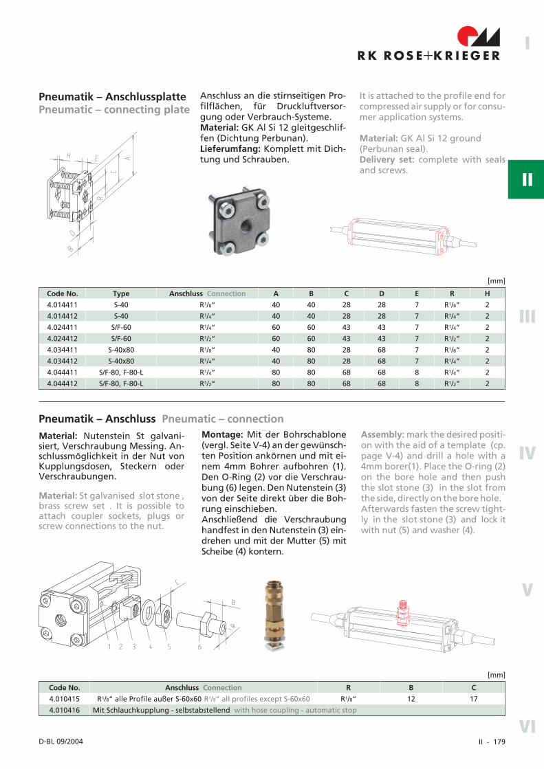
II - 179
R K R OS E K R I EG E R+I
II
IV
III
V
VID-BL 09/2004
Pneumatik – AnschlussplattePneumatic – connecting plate
Anschluss an die stirnseitigen Pro-filflächen, für Druckluftversor-gung oder Verbrauch-Systeme.Material: GK Al Si 12 gleitgeschlif-fen (Dichtung Perbunan).Lieferumfang: Komplett mit Dich-tung und Schrauben.
Code No. Anschluss Connection R B C
4.010415 R1/8“ alle Profile außer S-60x60 R1/8“ all profiles except S-60x60 R1/8“ 12 17
4.010416 Mit Schlauchkupplung - selbstabstellend with hose coupling - automatic stop
[mm]
Material: Nutenstein St galvani-siert, Verschraubung Messing. An-schlussmöglichkeit in der Nut vonKupplungsdosen, Steckern oderVerschraubungen.
Pneumatik – Anschluss Pneumatic – connection
Code No. Type Anschluss Connection A B C D E R H
4.014411 S-40 R1/8“ 40 40 28 28 7 R1/8” 2
4.014412 S-40 R1/4“ 40 40 28 28 7 R1/4” 2
4.024411 S/F-60 R1/4“ 60 60 43 43 7 R1/4” 2
4.024412 S/F-60 R1/2“ 60 60 43 43 7 R1/2” 2
4.034411 S-40x80 R1/8“ 40 80 28 68 7 R1/8” 2
4.034412 S-40x80 R1/4“ 40 80 28 68 7 R1/4” 2
4.044411 S/F-80, F-80-L R1/4“ 80 80 68 68 8 R1/4“ 2
4.044412 S/F-80, F-80-L R1/2“ 80 80 68 68 8 R1/2” 2
[mm]
It is attached to the profile end forcompressed air supply or for consu-mer application systems.
Material: GK Al Si 12 ground(Perbunan seal).Delivery set: complete with sealsand screws.
Montage: Mit der Bohrschablone(vergl. Seite V-4) an der gewünsch-ten Position ankörnen und mit ei-nem 4mm Bohrer aufbohren (1).Den O-Ring (2) vor die Verschrau-bung (6) legen. Den Nutenstein (3)von der Seite direkt über die Boh-rung einschieben.Anschließend die Verschraubunghandfest in den Nutenstein (3) ein-drehen und mit der Mutter (5) mitScheibe (4) kontern.
Material: St galvanised slot stone ,brass screw set . It is possible toattach coupler sockets, plugs orscrew connections to the nut.
Assembly: mark the desired positi-on with the aid of a template (cp.page V-4) and drill a hole with a4mm borer(1). Place the O-ring (2)on the bore hole and then pushthe slot stone (3) in the slot fromthe side, directly on the bore hole.Afterwards fasten the screw tight-ly in the slot stone (3) and lock itwith nut (5) and washer (4).
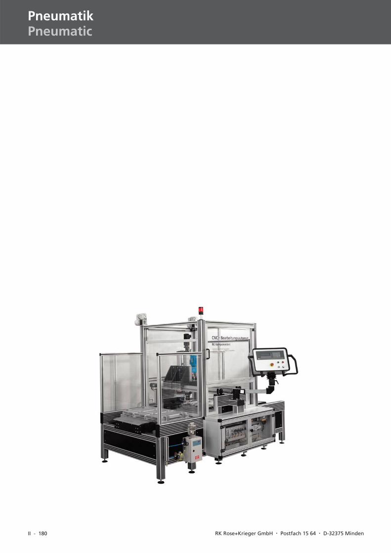
II - 180 RK Rose+Krieger GmbH � Postfach 15 64 � D-32375 Minden
PneumatikPneumatic