Embed Size (px)
Citation preview
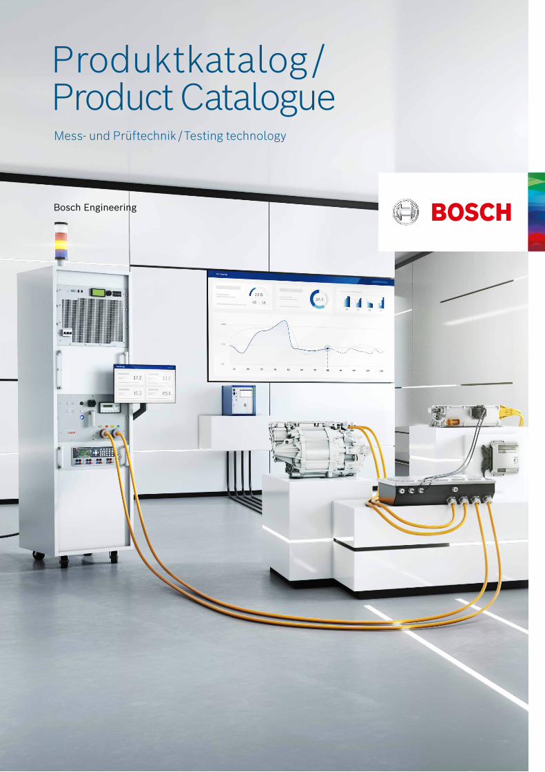
Produktkatalog / Product Catalogue Mess- und Prüftechnik / Testing technology
Produktkatalog Mess- und Prüftechnik2
Bosch Engineering GmbH, 2022
Prüfsteuersystem IPC-400 ....................................................4
Prüfsteuersystem IPC-450P .................................................5
Prüfsteuersystem IPC-201 ....................................................6
Prüfsteuergerät LabCON_V4 .................................................7
VDUE-Standard-Erweitert ....................................................8
VDUE-ROD-Erweitert ...........................................................9
μLC Test System ...................................................................10
µLC Erweiterungskarten .......................................................11
E-Mobility / HV-Produkte ......................................................14
Zubehör und Ersatzteile .......................................................15
Hardware Umbauservice (auf Anfrage) ..................................16
Kontaktpersonen ..................................................................30
Die Bosch Engineering GmbH beschäftigt sich seit 2002 inten-siv mit der Erbringung komplexer Testdienstleistungen, sowie der Entwicklung und Lieferung von individuellen Testgeräten in Kleinserien-Stückzahlen. Dabei fokussieren wir uns maßgeblich auf Testlösungen für Validierungs- und Verifizierungsaufgaben von Komponenten und vorintegrierten Subsystemen. Unsere Hardware- und Software-Expertise umfasst elektronische Steu-erungs- und Automatisierungsbaugruppen für Common-Rail- und Elektromobilitätsanwendungen.Der Betrieb von Systemen unter Prüfbedingungen stellt hohe Anforderungen an die eingesetzte Prüftechnik bezüglich Repro-duzierbarkeit und Zuverlässigkeit. Die Mess- und Prüfgeräte der Bosch Engineering GmbH wurden speziell für Anwendungen der Entwicklung, Dauererprobung und Qualitätssicherung entwi-ckelt, wobei kundenindividuelle Bedürfnisse stets im Vorder-grund stehen. Wesentliche Merkmale der Prüfgeräte sind die einfache und auf den jeweiligen Test- und Erprobungsfall zu-geschnittene Bedienbarkeit sowie maßgeschneiderte Pakete, welche im Systemverbund Prüfgerät, Kabelbäume, Adapter und Bediensoftware enthalten.
Wir bieten: f Entwicklung & Beratung
Lösungsorientierte Entwicklungsdienstleistung und Bera-tung mit Fokus auf Prüfverfahren, Validierung und Prototy-penerstellung für individuelle Prüfaufgaben an Systemen und Einzelkomponenten.
f Prüfsteuergeräte in Kleinserie Frühe Bereitstellung von Prototypen zur Funktionsvalidie-rung, sowie Entwicklung und Lieferung von Prüfgeräten unabhängig von der Stückzahl.
f Service Umfassender Service aus einer Hand inkl. Serienbetreu-ung, technischer Support und Reparaturservice für unsere Prüfgeräte.
Sollten wir für Ihren Testzweck keine geeigneten Geräte oder Methoden haben, helfen wir Ihnen natürlich gerne bei der Ent-wicklung einer maßgeschneiderten Lösung.
Individuelle Testinglösungen Inhalt
Bosch Engineering GmbH, 2022
Product catalogue Testing technology3
Since 2002 Bosch Engineering GmbH is intensively engaged in the provision of complex test services, as well as developing and delivering of individual testing devices in small batch quan-tities. We focus on testing solutions for validation and verifica-tion tasks on component and pre-integrated level. Our hard-ware and software expertise includes electronic control and automation devices for common rail and electro mobility applications. Operating complex systems under testing conditions creates high demands on the equipment regarding reproducibility and reliability of the results. The testing equipment of Bosch Engi-neering GmbH has been developed for applications in product development, endurance testing and quality assurance – with a focus on individual customer needs. Key features of the testing equipment are the ease of usability and the tailoring to the respective application. You will receive a package tailored to your specific needs including of tester, wiring harness, adapters and operating software.
We offer: f Development & Consulting
Solution-oriented development and consulting services with a focus on test procedures, function validation and sample building for individual testing tasks on systems and components.
f Test control units Early preparation of prototypes for function validation, as well as development and delivery of testing devices from prototype to small series.
f Service Comprehensive service from a single source, incl. series production care, technical support and repair service on our testing devices.
In case we do not have testing devices or testing methods readily suitable for your application we will gladly support you to develop a customized solution.
Individualizedtesting solutions Content
Test control system IPC-400..................................................17
Test control system IPC-450P ...............................................18
Test control system IPC-201 .................................................19
Test control unit LabCON_V4 ................................................20
VDUE-Standard-Extended .....................................................21
VDUE-ROD-Extended ............................................................22
μLC Test System ...................................................................23
µLC Expansion Boards ..........................................................24
E-mobility/ HV-products .......................................................27
Accessories and spare parts .................................................28
Hardware update service (upon request) .............................29
Contact persons ...................................................................30
Produktkatalog Mess- und Prüftechnik4
Bosch Engineering GmbH, 2022
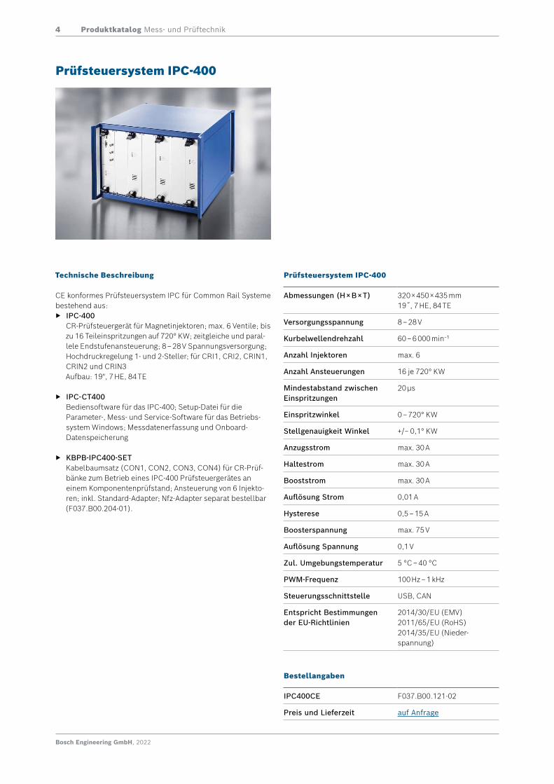
Technische Beschreibung
CE konformes Prüfsteuersystem IPC für Common Rail Systeme bestehend aus:
f IPC-400 CR-Prüfsteuergerät für Magnetinjektoren; max. 6 Ventile; bis zu 16 Teileinspritzungen auf 720° KW; zeitgleiche und paral-lele Endstufenansteuerung; 8 – 28 V Spannungsversorgung; Hochdruckregelung 1- und 2-Steller; für CRI1, CRI2, CRIN1, CRIN2 und CRIN3 Aufbau: 19", 7 HE, 84 TE
f IPC-CT400 Bediensoftware für das IPC-400; Setup-Datei für die Parameter-, Mess- und Service-Software für das Betriebs-system Windows; Messdatenerfassung und Onboard- Datenspeicherung
f KBPB-IPC400-SET Kabelbaumsatz (CON1, CON2, CON3, CON4) für CR-Prüf-bänke zum Betrieb eines IPC-400 Prüfsteuergerätes an einem Komponentenprüfstand; Ansteuerung von 6 Injekto-ren; inkl. Standard-Adapter; Nfz-Adapter separat bestellbar (F037.B00.204-01).
Prüfsteuersystem IPC-400
Prüfsteuersystem IPC-400
Abmessungen (H × B × T) 320 × 450 × 435 mm 19˝, 7 HE, 84 TE
Versorgungsspannung 8 – 28 V
Kurbelwellendrehzahl 60 – 6 000 min−1
Anzahl Injektoren max. 6
Anzahl Ansteuerungen 16 je 720° KW
Mindestabstand zwischen Einspritzungen
20 µs
Einspritzwinkel 0 – 720° KW
Stellgenauigkeit Winkel +/− 0,1° KW
Anzugsstrom max. 30 A
Haltestrom max. 30 A
Booststrom max. 30 A
Auflösung Strom 0,01 A
Hysterese 0,5 – 15 A
Boosterspannung max. 75 V
Auflösung Spannung 0,1 V
Zul. Umgebungstemperatur 5 °C – 40 °C
PWM-Frequenz 100 Hz – 1 kHz
Steuerungsschnittstelle USB, CAN
Entspricht Bestimmungender EU-Richtlinien
2014/30/EU (EMV)2011/65/EU (RoHS)2014/35/EU (Nieder-spannung)
Bestellangaben
IPC400CE F037.B00.121-02
Preis und Lieferzeit auf Anfrage
Produktkatalog Mess- und Prüftechnik5
Bosch Engineering GmbH, 2022
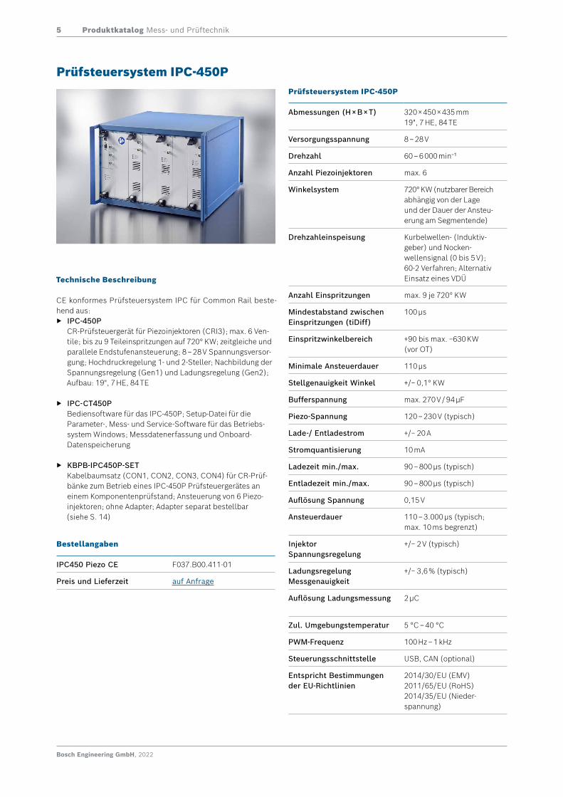
Technische Beschreibung
CE konformes Prüfsteuersystem IPC für Common Rail beste-hend aus:
f IPC-450P CR-Prüfsteuergerät für Piezoinjektoren (CRI3); max. 6 Ven-tile; bis zu 9 Teileinspritzungen auf 720° KW; zeitgleiche und parallele Endstufenansteuerung; 8 – 28 V Spannungsversor-gung; Hochdruckregelung 1- und 2-Steller; Nachbildung der Spannungsregelung (Gen1) und Ladungsregelung (Gen2); Aufbau: 19", 7 HE, 84 TE
f IPC-CT450P Bediensoftware für das IPC-450P; Setup-Datei für die Parameter-, Mess- und Service-Software für das Betriebs-system Windows; Messdatenerfassung und Onboard- Datenspeicherung
f KBPB-IPC450P-SET Kabelbaumsatz (CON1, CON2, CON3, CON4) für CR-Prüf-bänke zum Betrieb eines IPC-450P Prüfsteuergerätes an einem Komponentenprüfstand; Ansteuerung von 6 Piezo-injektoren; ohne Adapter; Adapter separat bestellbar (siehe S. 14)
Prüfsteuersystem IPC-450PPrüfsteuersystem IPC-450P
Abmessungen (H × B × T) 320 × 450 × 435 mm 19", 7 HE, 84 TE
Versorgungsspannung 8 – 28 V
Drehzahl 60 – 6 000 min−1
Anzahl Piezoinjektoren max. 6
Winkelsystem 720° KW (nutzbarer Bereich abhängig von der Lage und der Dauer der Ansteu-erung am Segmentende)
Drehzahleinspeisung Kurbelwellen- (Induktiv-geber) und Nocken-wellensignal (0 bis 5 V); 60-2 Verfahren; Alternativ Einsatz eines VDÜ
Anzahl Einspritzungen max. 9 je 720° KW
Mindestabstand zwischen Einspritzungen (tiDiff)
100 µs
Einspritzwinkelbereich +90 bis max. −630 KW (vor OT)
Minimale Ansteuerdauer 110 μs
Stellgenauigkeit Winkel +/− 0,1° KW
Bufferspannung max. 270 V / 94 µF
Piezo-Spannung 120 – 230 V (typisch)
Lade-/ Entladestrom +/− 20 A
Stromquantisierung 10 mA
Ladezeit min./max. 90 – 800 µs (typisch)
Entladezeit min./max. 90 – 800 µs (typisch)
Auflösung Spannung 0,15 V
Ansteuerdauer 110 – 3.000 μs (typisch; max. 10 ms begrenzt)
Injektor Spannungsregelung
+/− 2 V (typisch)
Ladungsregelung Messgenauigkeit
+/− 3,6 % (typisch)
Auflösung Ladungsmessung 2 μC
Zul. Umgebungstemperatur 5 °C – 40 °C
PWM-Frequenz 100 Hz – 1 kHz
Steuerungsschnittstelle USB, CAN (optional)
Entspricht Bestimmungender EU-Richtlinien
2014/30/EU (EMV)2011/65/EU (RoHS)2014/35/EU (Nieder-spannung)
Bestellangaben
IPC450 Piezo CE F037.B00.411-01
Preis und Lieferzeit auf Anfrage
Produktkatalog Mess- und Prüftechnik6
Bosch Engineering GmbH, 2022
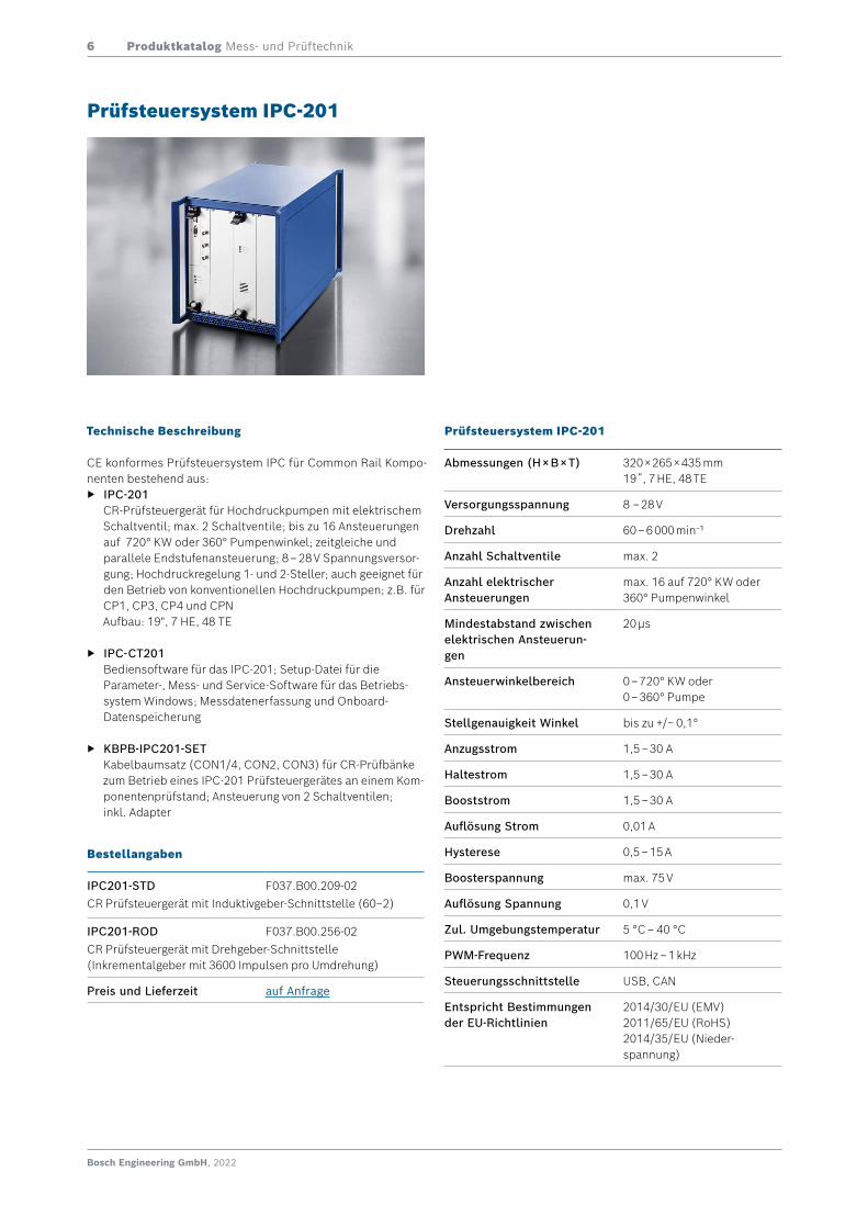
Technische Beschreibung
CE konformes Prüfsteuersystem IPC für Common Rail Kompo-nenten bestehend aus:
f IPC-201 CR-Prüfsteuergerät für Hochdruckpumpen mit elektrischem Schaltventil; max. 2 Schaltventile; bis zu 16 Ansteuerungen auf 720° KW oder 360° Pumpenwinkel; zeitgleiche und parallele Endstufenansteuerung; 8 – 28 V Spannungsversor-gung; Hochdruckregelung 1- und 2-Steller; auch geeignet für den Betrieb von konventionellen Hochdruckpumpen; z.B. für CP1, CP3, CP4 und CPN Aufbau: 19", 7 HE, 48 TE
f IPC-CT201 Bediensoftware für das IPC-201; Setup-Datei für die Parameter-, Mess- und Service-Software für das Betriebs-system Windows; Messdatenerfassung und Onboard- Datenspeicherung
f KBPB-IPC201-SET Kabelbaumsatz (CON1/4, CON2, CON3) für CR-Prüfbänke zum Betrieb eines IPC-201 Prüfsteuergerätes an einem Kom-ponentenprüfstand; Ansteuerung von 2 Schaltventilen; inkl. Adapter
Prüfsteuersystem IPC-201
Prüfsteuersystem IPC-201
Abmessungen (H × B × T) 320 × 265 × 435 mm 19˝, 7 HE, 48 TE
Versorgungsspannung 8 – 28 V
Drehzahl 60 – 6 000 min−1
Anzahl Schaltventile max. 2
Anzahl elektrischer Ansteuerungen
max. 16 auf 720° KW oder 360° Pumpenwinkel
Mindestabstand zwischen elektrischen Ansteuerun-gen
20 µs
Ansteuerwinkelbereich 0 – 720° KW oder 0 – 360° Pumpe
Stellgenauigkeit Winkel bis zu +/− 0,1°
Anzugsstrom 1,5 – 30 A
Haltestrom 1,5 – 30 A
Booststrom 1,5 – 30 A
Auflösung Strom 0,01 A
Hysterese 0,5 – 15 A
Boosterspannung max. 75 V
Auflösung Spannung 0,1 V
Zul. Umgebungstemperatur 5 °C – 40 °C
PWM-Frequenz 100 Hz – 1 kHz
Steuerungsschnittstelle USB, CAN
Entspricht Bestimmungender EU-Richtlinien
2014/30/EU (EMV)2011/65/EU (RoHS)2014/35/EU (Nieder-spannung)
Bestellangaben
IPC201-STD F037.B00.209-02CR Prüfsteuergerät mit Induktivgeber-Schnittstelle (60–2)
IPC201-ROD F037.B00.256-02CR Prüfsteuergerät mit Drehgeber-Schnittstelle(Inkrementalgeber mit 3600 Impulsen pro Umdrehung)
Preis und Lieferzeit auf Anfrage
Produktkatalog Mess- und Prüftechnik7
Bosch Engineering GmbH, 2022
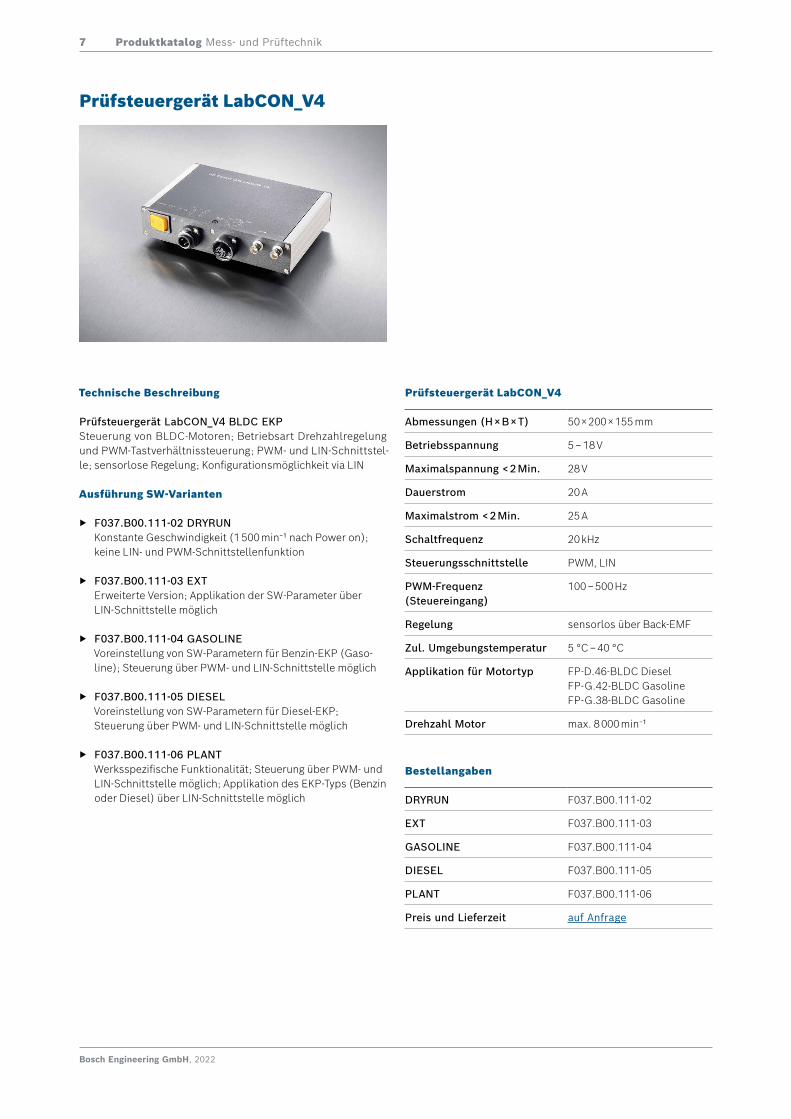
Technische Beschreibung
Prüfsteuergerät LabCON_V4 BLDC EKPSteuerung von BLDC-Motoren; Betriebsart Drehzahlregelung und PWM-Tastverhältnissteuerung; PWM- und LIN-Schnittstel-le; sensorlose Regelung; Konfigurationsmöglichkeit via LIN
Ausführung SW-Varianten
f F037.B00.111-02 DRYRUN Konstante Geschwindigkeit (1 500 min−1 nach Power on); keine LIN- und PWM-Schnittstellenfunktion
f F037.B00.111-03 EXT Erweiterte Version; Applikation der SW-Parameter über LIN-Schnittstelle möglich
f F037.B00.111-04 GASOLINE Voreinstellung von SW-Parametern für Benzin-EKP (Gaso-line); Steuerung über PWM- und LIN-Schnittstelle möglich
f F037.B00.111-05 DIESEL Voreinstellung von SW-Parametern für Diesel-EKP; Steuerung über PWM- und LIN-Schnittstelle möglich
f F037.B00.111-06 PLANT Werksspezifische Funktionalität; Steuerung über PWM- und LIN-Schnittstelle möglich; Applikation des EKP-Typs (Benzin oder Diesel) über LIN-Schnittstelle möglich
Prüfsteuergerät LabCON_V4
Prüfsteuergerät LabCON_V4
Abmessungen (H × B × T) 50 × 200 × 155 mm
Betriebsspannung 5 – 18 V
Maximalspannung < 2 Min. 28 V
Dauerstrom 20 A
Maximalstrom < 2 Min. 25 A
Schaltfrequenz 20 kHz
Steuerungsschnittstelle PWM, LIN
PWM-Frequenz (Steuereingang)
100 – 500 Hz
Regelung sensorlos über Back-EMF
Zul. Umgebungstemperatur 5 °C – 40 °C
Applikation für Motortyp FP-D.46-BLDC Diesel FP-G.42-BLDC GasolineFP-G.38-BLDC Gasoline
Drehzahl Motor max. 8 000 min−1
Bestellangaben
DRYRUN F037.B00.111-02
EXT F037.B00.111-03
GASOLINE F037.B00.111-04
DIESEL F037.B00.111-05
PLANT F037.B00.111-06
Preis und Lieferzeit auf Anfrage

Produktkatalog Mess- und Prüftechnik8
Bosch Engineering GmbH, 2022
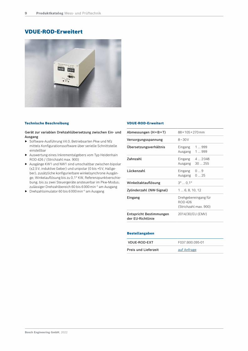
Technische Beschreibung
Gerät zur variablen Drehzahlübersetzung zwischen Ein- und Ausgang
f Software-Ausführung V4.0; Betriebsarten Pkw und Nfz mittels Konfigurationssoftware über serielle Schnittstelle einstellbar
f Auswertung eines induktiven KW-Sensors (differentiell) f Ausgänge KW1 und NW1 sind umschaltbar zwischen bipolar
(±2,5 V, induktive Geber) und unipolar (0 bis +5 V, Hallge-ber); zusätzliche konfigurierbare winkelsynchrone Ausgän-ge; Winkelauflösung bis zu 0,1° KW, Referenzpunktverschie-bung; bis zu zwei Steuergeräte ansteuerbar im Pkw-Modus; zulässiger Drehzahlbereich 60 bis 6 000 min−1 am Ausgang
f Drehzahlsimulator 60 bis 6 000 min−1 am Ausgang
VDUE-Standard-Erweitert
VDUE-Standard-Erweitert
Abmessungen (H × B × T) 88 × 105 × 270 mm
Versorgungsspannung 8 – 30 V
Übersetzungsverhältnis Eingang 1 … 999Ausgang 1 … 999
Zahnzahl Eingang 4 … 2 048Ausgang 30 … 255
Lückenzahl Eingang 0 … 9Ausgang 0 … 25
Winkeltaktauflösung 3° … 0,1°
Zylinderzahl (NW-Signal) 1 … 6, 8, 10, 12
Eingang Drehzahleingang für InduktivgeberReferenzeingang: Hall
Entspricht Bestimmungender EU-Richtlinie
2014/30/EU (EMV)
Bestellangaben
VDUE-STD-EXT F037.B00.094-01
Preis und Lieferzeit auf Anfrage
Produktkatalog Mess- und Prüftechnik9
Bosch Engineering GmbH, 2022
Technische Beschreibung
Gerät zur variablen Drehzahlübersetzung zwischen Ein- und Ausgang
f Software-Ausführung V4.0; Betriebsarten Pkw und Nfz mittels Konfigurationssoftware über serielle Schnittstelle einstellbar
f Auswertung eines Inkrementalgebers vom Typ Heidenhain ROD 426 / (Strichzahl max. 900)
f Ausgänge KW1 und NW1 sind umschaltbar zwischen bipolar (±2,5 V, induktive Geber) und unipolar (0 bis +5 V, Hallge-ber); zusätzliche konfigurierbare winkelsynchrone Ausgän-ge; Winkelauflösung bis zu 0,1° KW, Referenzpunktverschie-bung; bis zu zwei Steuergeräte ansteuerbar im Pkw-Modus; zulässiger Drehzahlbereich 60 bis 6 000 min−1 am Ausgang
f Drehzahlsimulator 60 bis 6 000 min−1 am Ausgang
VDUE-ROD-Erweitert
VDUE-ROD-Erweitert
Abmessungen (H × B × T) 88 × 105 × 270 mm
Versorgungsspannung 8 – 30 V
Übersetzungsverhältnis Eingang 1 … 999Ausgang 1 … 999
Zahnzahl Eingang 4 … 2 048Ausgang 30 … 255
Lückenzahl Eingang 0 … 9Ausgang 0 … 25
Winkeltaktauflösung 3° … 0,1°
Zylinderzahl (NW-Signal) 1 … 6, 8, 10, 12
Eingang Drehgebereingang für ROD 426 (Strichzahl max. 900)
Entspricht Bestimmungender EU-Richtlinie
2014/30/EU (EMV)
Bestellangaben
VDUE-ROD-EXT F037.B00.095-01
Preis und Lieferzeit auf Anfrage
Produktkatalog Mess- und Prüftechnik10
Bosch Engineering GmbH, 2022
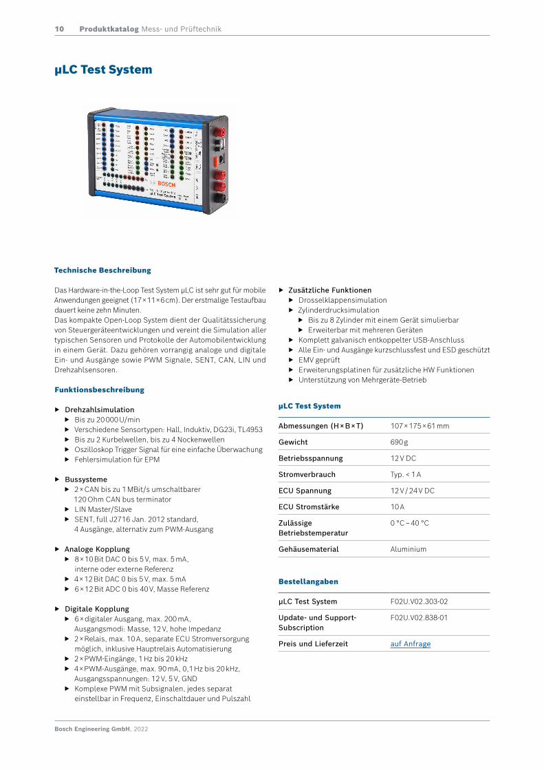
Technische Beschreibung
Das Hardware-in-the-Loop Test System μLC ist sehr gut für mobile Anwendungen geeignet (17 × 11 × 6 cm). Der erstmalige Testaufbau dauert keine zehn Minuten. Das kompakte Open-Loop System dient der Qualitätssicherung von Steuergeräteentwicklungen und vereint die Simulation aller typischen Sensoren und Protokolle der Automobilentwicklung in einem Gerät. Dazu gehören vorrangig analoge und digitale Ein- und Ausgänge sowie PWM Signale, SENT, CAN, LIN und Drehzahlsensoren.
Funktionsbeschreibung
f Drehzahlsimulation f Bis zu 20 000 U/min f Verschiedene Sensortypen: Hall, Induktiv, DG23i, TL4953 f Bis zu 2 Kurbelwellen, bis zu 4 Nockenwellen f Oszilloskop Trigger Signal für eine einfache Überwachung f Fehlersimulation für EPM
f Bussysteme f 2 × CAN bis zu 1 MBit/s umschaltbarer
120 Ohm CAN bus terminator f LIN Master/Slave f SENT, full J2716 Jan. 2012 standard,
4 Ausgänge, alternativ zum PWM-Ausgang
f Analoge Kopplung f 8 × 10 Bit DAC 0 bis 5 V, max. 5 mA,
interne oder externe Referenz f 4 × 12 Bit DAC 0 bis 5 V, max. 5 mA f 6 × 12 Bit ADC 0 bis 40 V, Masse Referenz
f Digitale Kopplung f 6 × digitaler Ausgang, max. 200 mA,
Ausgangsmodi: Masse, 12 V, hohe Impedanz f 2 × Relais, max. 10 A, separate ECU Stromversorgung
möglich, inklusive Hauptrelais Automatisierung f 2 × PWM-Eingänge, 1 Hz bis 20 kHz f 4 × PWM-Ausgänge, max. 90 mA, 0,1 Hz bis 20 kHz,
Ausgangsspannungen: 12 V, 5 V, GND f Komplexe PWM mit Subsignalen, jedes separat
einstellbar in Frequenz, Einschaltdauer und Pulszahl
µLC Test System
µLC Test System
Abmessungen (H × B × T) 107 × 175 × 61 mm
Gewicht 690 g
Betriebsspannung 12 V DC
Stromverbrauch Typ. < 1 A
ECU Spannung 12 V / 24 V DC
ECU Stromstärke 10 A
Zulässige Betriebstemperatur
0 °C – 40 °C
Gehäusematerial Aluminium
Bestellangaben
µLC Test System F02U.V02.303-02
Update- und Support-Subscription
F02U.V02.838-01
Preis und Lieferzeit auf Anfrage
f Zusätzliche Funktionen f Drosselklappensimulation f Zylinderdrucksimulation
f Bis zu 8 Zylinder mit einem Gerät simulierbar f Erweiterbar mit mehreren Geräten
f Komplett galvanisch entkoppelter USB-Anschluss f Alle Ein- und Ausgänge kurzschlussfest und ESD geschützt f EMV geprüft f Erweiterungsplatinen für zusätzliche HW Funktionen f Unterstützung von Mehrgeräte-Betrieb
Produktkatalog Mess- und Prüftechnik11
Bosch Engineering GmbH, 2022
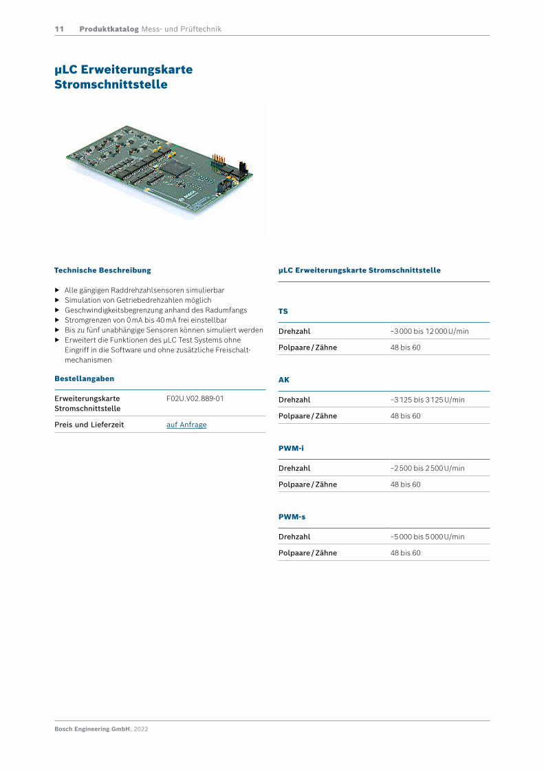
Technische Beschreibung
f Alle gängigen Raddrehzahlsensoren simulierbar f Simulation von Getriebedrehzahlen möglich f Geschwindigkeitsbegrenzung anhand des Radumfangs f Stromgrenzen von 0 mA bis 40 mA frei einstellbar f Bis zu fünf unabhängige Sensoren können simuliert werden f Erweitert die Funktionen des μLC Test Systems ohne
Eingriff in die Software und ohne zusätzliche Freischalt-mechanismen
µLC Erweiterungskarte Stromschnittstelle
µLC Erweiterungskarte Stromschnittstelle
TS
Drehzahl −3 000 bis 12 000 U/min
Polpaare / Zähne 48 bis 60
AK
Drehzahl −3 125 bis 3 125 U/min
Polpaare / Zähne 48 bis 60
PWM-i
Drehzahl −2 500 bis 2 500 U/min
Polpaare / Zähne 48 bis 60
PWM-s
Drehzahl −5 000 bis 5 000 U/min
Polpaare / Zähne 48 bis 60
Bestellangaben
ErweiterungskarteStromschnittstelle
F02U.V02.889-01
Preis und Lieferzeit auf Anfrage
Produktkatalog Mess- und Prüftechnik12
Bosch Engineering GmbH, 2022
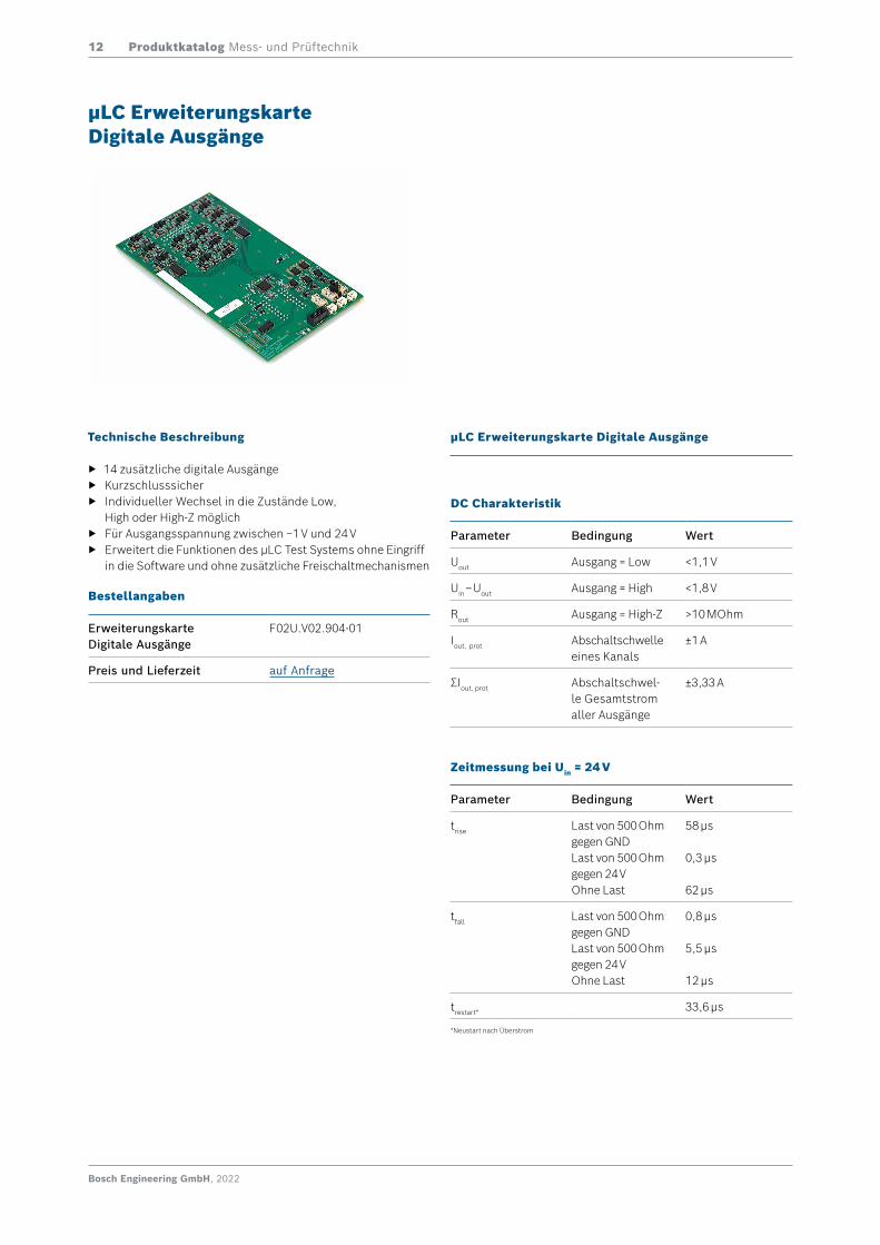
Technische Beschreibung
f 14 zusätzliche digitale Ausgänge f Kurzschlusssicher f Individueller Wechsel in die Zustände Low,
High oder High-Z möglich f Für Ausgangsspannung zwischen −1 V und 24 V f Erweitert die Funktionen des μLC Test Systems ohne Eingriff
in die Software und ohne zusätzliche Freischaltmechanismen
µLC Erweiterungskarte Digitale Ausgänge
µLC Erweiterungskarte Digitale Ausgänge
DC Charakteristik
Parameter Bedingung Wert
Uout Ausgang = Low <1,1 V
Uin – Uout Ausgang = High <1,8 V
Rout Ausgang = High-Z >10 MOhm
Iout, prot Abschaltschwelle eines Kanals
±1 A
ΣIout, prot Abschaltschwel-le Gesamtstrom aller Ausgänge
±3,33 A
Zeitmessung bei Uin = 24 V
Parameter Bedingung Wert
trise Last von 500 Ohm gegen GNDLast von 500 Ohm gegen 24 VOhne Last
58 μs
0,3 μs
62 μs
tfall Last von 500 Ohm gegen GNDLast von 500 Ohm gegen 24 VOhne Last
0,8 μs
5,5 μs
12 μs
trestart* 33,6 μs
Bestellangaben
ErweiterungskarteDigitale Ausgänge
F02U.V02.904-01
Preis und Lieferzeit auf Anfrage
*Neustart nach Überstrom
Produktkatalog Mess- und Prüftechnik13
Bosch Engineering GmbH, 2022
Technische Beschreibung
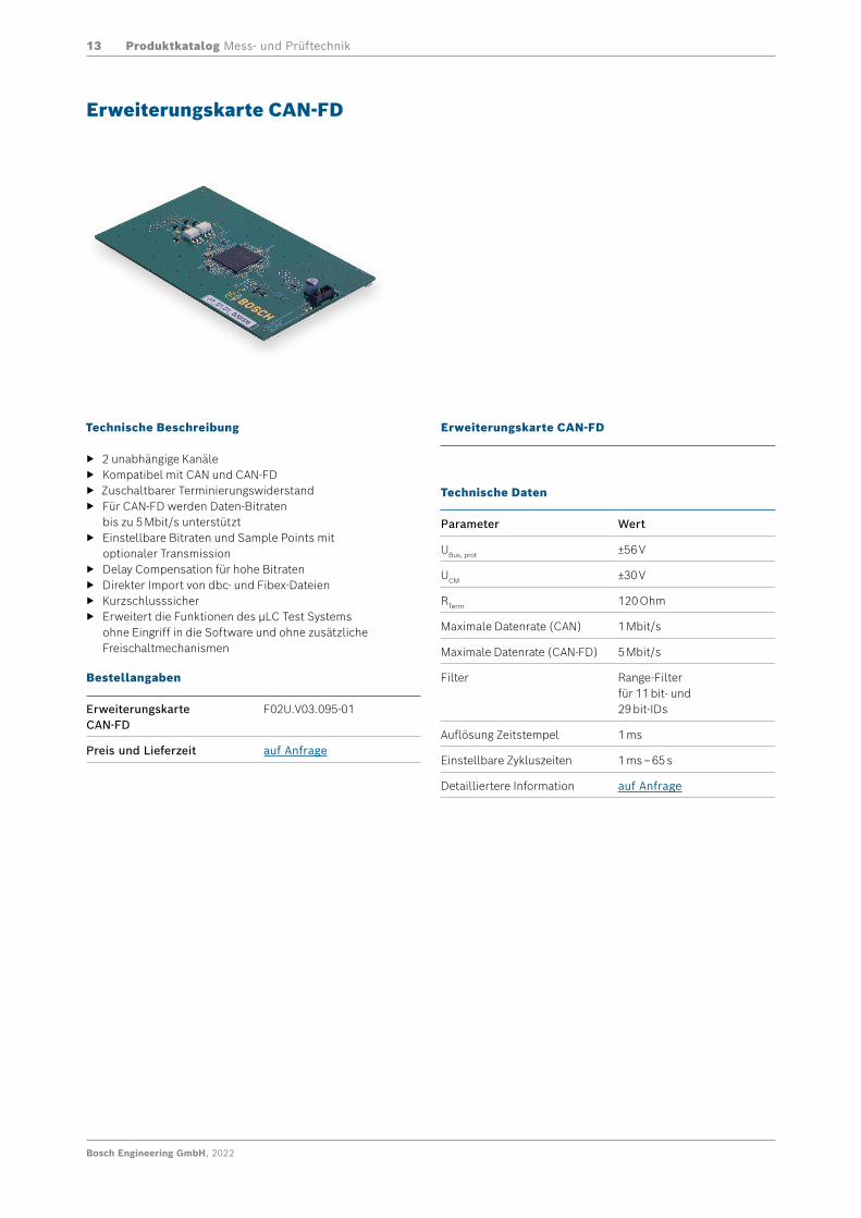
f 2 unabhängige Kanäle f Kompatibel mit CAN und CAN-FD f Zuschaltbarer Terminierungswiderstand f Für CAN-FD werden Daten-Bitraten
bis zu 5 Mbit/s unterstützt f Einstellbare Bitraten und Sample Points mit
optionaler Transmission f Delay Compensation für hohe Bitraten f Direkter Import von dbc- und Fibex-Dateien f Kurzschlusssicher f Erweitert die Funktionen des μLC Test Systems
ohne Eingriff in die Software und ohne zusätzliche Freischaltmechanismen
Erweiterungskarte CAN-FD
Bestellangaben
ErweiterungskarteCAN-FD
F02U.V03.095-01
Preis und Lieferzeit auf Anfrage
Erweiterungskarte CAN-FD
Technische Daten
Parameter Wert
UBus, prot ±56 V
UCM ±30 V
RTerm 120 Ohm
Maximale Datenrate (CAN) 1 Mbit/s
Maximale Datenrate (CAN-FD) 5 Mbit/s
Filter Range-Filterfür 11 bit- und29 bit-IDs
Auflösung Zeitstempel 1 ms
Einstellbare Zykluszeiten 1 ms – 65 s
Detailliertere Information auf Anfrage
Produktkatalog Mess- und Prüftechnik14
Bosch Engineering GmbH, 2022
Lösungen
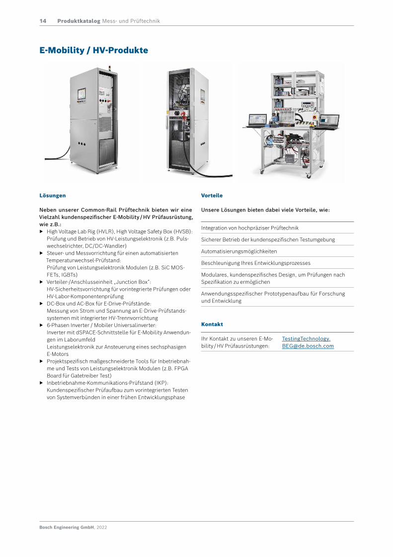
Neben unserer Common-Rail Prüftechnik bieten wir eine Vielzahl kundenspezifischer E-Mobility / HV Prüfausrüstung, wie z.B.:
f High Voltage Lab Rig (HVLR), High Voltage Safety Box (HVSB): Prüfung und Betrieb von HV-Leistungselektronik (z.B. Puls-wechselrichter, DC/DC-Wandler)
f Steuer- und Messvorrichtung für einen automatisierten Temperaturwechsel-Prüfstand: Prüfung von Leistungselektronik Modulen (z.B. SiC MOS-FETs, IGBTs)
f Verteiler-/Anschlusseinheit „Junction Box“: HV-Sicherheitsvorrichtung für vorintegrierte Prüfungen oder HV-Labor-Komponentenprüfung
f DC-Box und AC-Box für E-Drive-Prüfstände: Messung von Strom und Spannung an E-Drive-Prüfstands-systemen mit integrierter HV-Trennvorrichtung
f 6-Phasen Inverter / Mobiler Universalinverter: Inverter mit dSPACE-Schnittstelle für E-Mobility Anwendun-gen im Laborumfeld Leistungselektronik zur Ansteuerung eines sechsphasigen E-Motors
f Projektspezifisch maßgeschneiderte Tools für Inbetriebnah-me und Tests von Leistungselektronik Modulen (z.B. FPGA Board für Gatetreiber Test)
f Inbetriebnahme-Kommunikations-Prüfstand (IKP): Kundenspezifischer Prüfaufbau zum vorintegrierten Testen von Systemverbünden in einer frühen Entwicklungsphase
E-Mobility / HV-Produkte
Integration von hochpräziser Prüftechnik
Sicherer Betrieb der kundenspezifischen Testumgebung
Automatisierungsmöglichkeiten
Beschleunigung Ihres Entwicklungsprozesses
Modulares, kundenspezifisches Design, um Prüfungen nach Spezifikation zu ermöglichen
Anwendungsspezifischer Prototypenaufbau für Forschung und Entwicklung
Kontakt
Ihr Kontakt zu unseren E-Mo-bility / HV Prüfausrüstungen:
Vorteile
Unsere Lösungen bieten dabei viele Vorteile, wie:
Produktkatalog Mess- und Prüftechnik15
Bosch Engineering GmbH, 2022
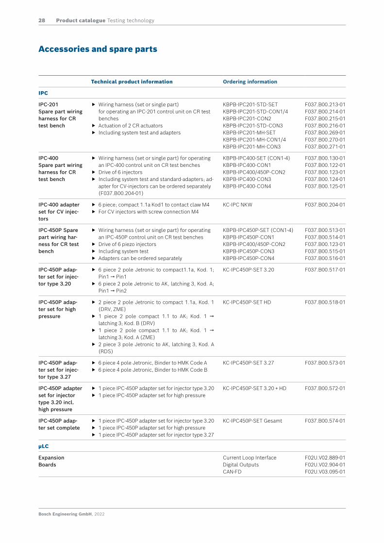
Zubehör und Ersatzteile
Beschreibung Bestellangaben
IPC
IPC-201 Ersatzkabelbäu-me für CR-Prüf-bänke
f Kabelbaumsatz (SET) oder Teilkabelbaum für CR-Prüfbänke zum Betrieb eines IPC-201 Prüfsteuergerätes
f Ansteuerung von 2 Schaltventilen f Inklusive Prüfung und Adapter
KBPB-IPC201-STD-SETKBPB-IPC201-STD-CON1/4KBPB-IPC201-CON2KBPB-IPC201-STD-CON3KBPB-IPC201-MH-SETKBPB-IPC201-MH-CON1/4KBPB-IPC201-MH-CON3
F037.B00.213-01F037.B00.214-01F037.B00.215-01F037.B00.216-01F037.B00.269-01F037.B00.270-01F037.B00.271-01
IPC-400Ersatzkabelbäu-me für CR-Prüf-bänke
f Kabelbaumsatz (SET) oder Teilkabelbaum für CR-Prüfbänke zum Betrieb eines IPC-400 Prüfsteuergerätes
f Ansteuerung von 6 Injektoren f Inklusive Prüfung und Standard-Adapter; Nfz-Ad-
apter separat bestellbar (F037.B00.204-01)
KBPB-IPC400-SET (CON1-4)KBPB-IPC400-CON1KBPB-IPC400/450P-CON2KBPB-IPC400-CON3KBPB-IPC400-CON4
F037.B00.130-01F037.B00.122-01F037.B00.123-01F037.B00.124-01F037.B00.125-01
IPC-400 Adapter-set für Nfz-Injek-toren
f 6 Stück Kompakt 1.1a Kod1 auf Kralle M4 f Für Nfz-Injektoren mit M4 Schraubanschlüssen
KC-IPC NKW F037.B00.204-01
IPC-450P Ersatz-kabelbäume für CR-Prüfbänke
f Kabelbaumsatz (SET) oder Teilkabelbaum für CR-Prüfbänke zum Betrieb eines IPC-450P Prüf-steuergerätes
f Ansteuerung von 6 Piezo-Injektoren f Inklusive Prüfung f Adapter seperat bestellbar
KBPB-IPC450P-SET(CON1-4)KBPB-IPC450P-CON1KBPB-IPC400/450P-CON2KBPB-IPC450P-CON3KBPB-IPC450P-CON4
F037.B00.513-01F037.B00.514-01F037.B00.123-01F037.B00.515-01F037.B00.516-01
IPC-450P Adap-terset für Injek-tortyp 3.20
f 6 Stück 2 pol Jetronic auf Kompakt1.1a, Kod. 1; Pin1 Pin1
f 6 Stück 2 pol Jetronic auf AK, Verrastung 3, Kod. A; Pin1 Pin2
KC-IPC450P-SET 3.20 F037.B00.517-01
IPC-450P Adap-terset für Hoch-druck
f 2 Stück 2 pol Jetronic auf Kompakt 1.1a, Kod. 1 (DRV, ZME)
f 1 Stück 2 pol Kompakt 1.1 auf AK; Kod. 1 Verrastung 3; Kod. B (DRV)
f 1 Stück 2 pol Kompakt 1.1 auf AK; Kod. 1 Verrastung 3; Kod. A (ZME)
f 2 Stück 3 pol Jetronic auf AK, Verrastung 3, Kod. A (RDS)
KC-IPC450P-SET HD F037.B00.518-01
IPC-450P Adap-terset für Injek-tortyp 3.27
f 6 Stück 4 pol Jetronic, Binder auf HMK Code A f 6 Stück 4 pol Jetronic, Binder auf HMK Code B
KC-IPC450P-SET 3.27 F037.B00.573-01
IPC-450P Adap-terset für Injek-tortyp 3.20 inkl. Hochdruck
f 1 Stück IPC-450P Adapterset für Injektortyp 3.20 f 1 Stück IPC-450P Adapterset für Hochdruck
KC-IPC450P-SET 3.20 + HD F037.B00.572-01
IPC-450P Adap-terset Gesamt
f 1 Stück IPC-450P Adapterset für Injektortyp 3.20 f 1 Stück IPC-450P Adapterset für Hochdruck f 1 Stück IPC-450P Adapterset für Injektortyp 3.27
KC-IPC450P-SET Gesamt F037.B00.574-01
µLC
Erweiterungs-karten
StromschnittstelleDigitale Ausgänge CAN-FD
F02U.V02.889-01F02U.V02.904-01F02U.V03.095-01
Produktkatalog Mess- und Prüftechnik16
Bosch Engineering GmbH, 2022
Beschreibung Bestellangaben
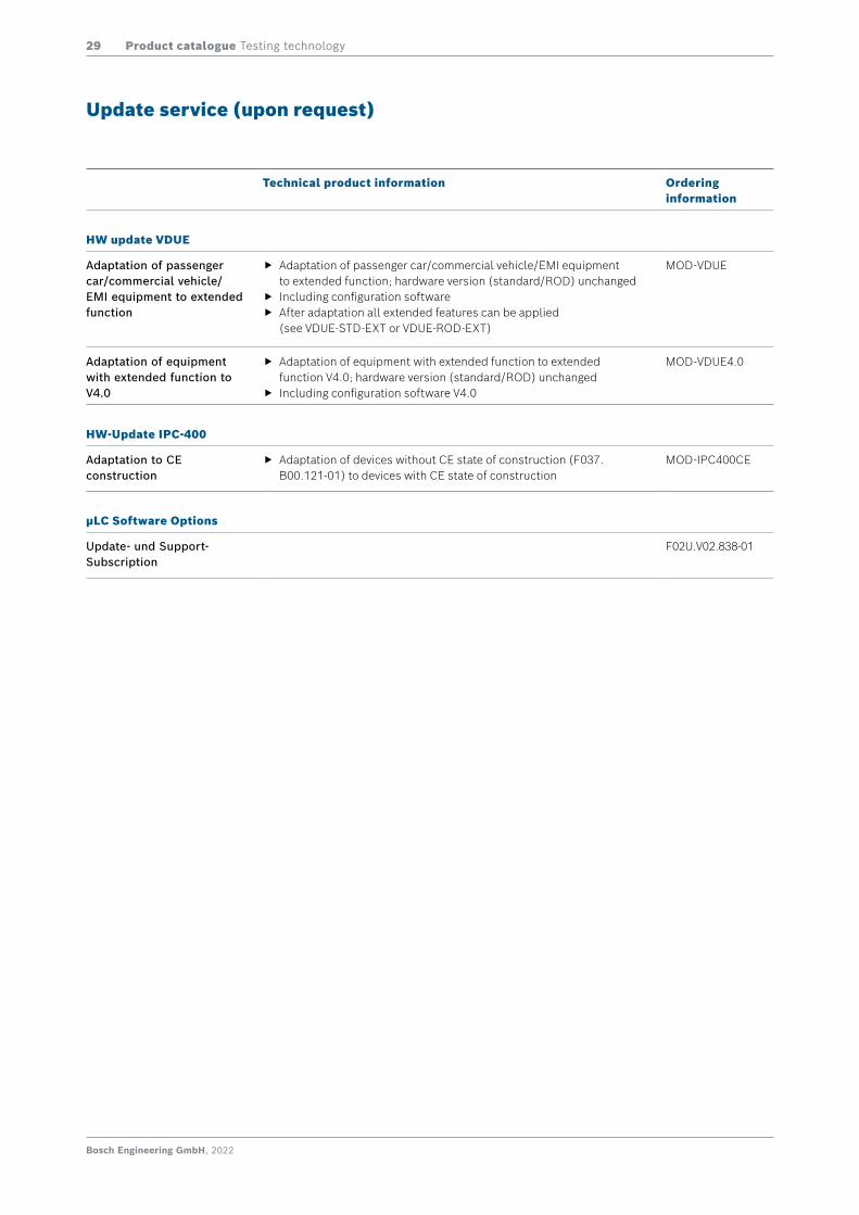
HW-Update VDUE
Umbau von Pkw/Nfz/EMI-Geräten auf Geräte mit erweiterter Funktion
f Umbau von Pkw/Nfz/EMI-Geräten auf Geräte mit erweiterter Funktion; Hardware-Variante (Standard/ROD) bleibt unverändert
f Inkl. Konfigurationssoftware f Nach dem Umbau stehen alle Features der Geräte VDUE-STD-EXT
bzw. VDUE-ROD-EXT zur Verfügung
MOD-VDUE
Umbau von Geräten mit erweiterter Funktion auf V4.0
f Umbau von Geräten mit erweiterter Funktion auf Geräte mit erweiterter Funktion V4.0; Hardware-Variante (Standard/ROD) bleibt unverändert
f Inkl. Konfigurationssoftware V4.0
MOD-VDUE4.0
Update Service (auf Anfrage)
HW-Update IPC-400
Umbau auf CE-Bauzustand f Umbau von Geräten ohne CE-Bauzustand (F037.B00.121-01) zu Geräten mit CE-Bauzustand
MOD-IPC400CE
µLC Software Optionen
Update- und Support- Subscription
F02U.V02.838-01
Bosch Engineering GmbH, 2022
Product catalogue Testing technology17
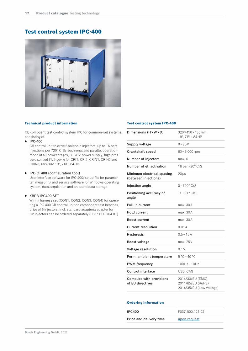
Technical product information
CE compliant test control system IPC for common-rail systems consisting of:
f IPC-400 CR control unit to drive 6 solenoid injectors; up to 16 part injections per 720° CrS; isochronal and parallel operation mode of all power stages; 8 – 28 V-power supply; high pres-sure control (1/2-gov.); for CRI1, CRI2, CRIN1, CRIN2 and CRIN3; rack size 19", 7 RU, 84 HP
f IPC-CT400 (configuration tool) User interface software for IPC-400; setup-file for parame-ter, measuring and service software for Windows operating system; data acquisition and on-board data storage
f KBPB-IPC400-SET Wiring harness set (CON1, CON2, CON3, CON4) for opera-ting a IPC-400 CR control unit on component test benches; drive of 6 injectors; incl. standard-adapters; adapter for CV-injectors can be ordered separately (F037.B00.204-01)
Test control system IPC-400
Test control system IPC-400
Dimensions (H × W × D) 320 × 450 × 435 mm 19", 7 RU, 84 HP
Supply voltage 8 – 28 V
Crankshaft speed 60 – 6,000 rpm
Number of injectors max. 6
Number of el. activation 16 per 720° CrS
Minimum electrical spacing (between injections)
20 µs
Injection angle 0 – 720° CrS
Positioning accuracy of angle
+/− 0,1° CrS
Pull-in current max. 30 A
Hold current max. 30 A
Boost current max. 30 A
Current resolution 0.01 A
Hysteresis 0.5 – 15 A
Boost voltage max. 75 V
Voltage resolution 0.1 V
Perm. ambient temperature 5 °C – 40 °C
PWM-frequency 100 Hz – 1 kHz
Control interface USB, CAN
Complies with provisions of EU directives
2014/30/EU (EMC) 2011/65/EU (RoHS) 2014/35/EU (Low Voltage)
Ordering information
IPC400 F037.B00.121-02
Price and delivery time upon request
Bosch Engineering GmbH, 2022
Product catalogue Testing technology18
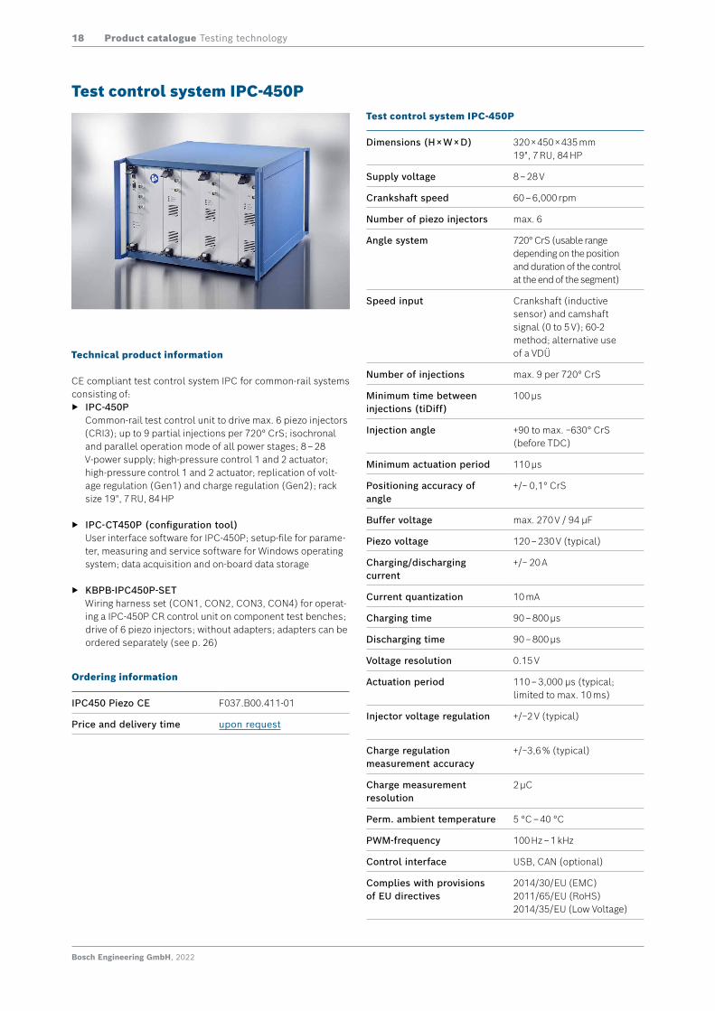
Technical product information
CE compliant test control system IPC for common-rail systems consisting of:
f IPC-450P Common-rail test control unit to drive max. 6 piezo injectors (CRI3); up to 9 partial injections per 720° CrS; isochronal and parallel operation mode of all power stages; 8 – 28 V-power supply; high-pressure control 1 and 2 actuator; high-pressure control 1 and 2 actuator; replication of volt-age regulation (Gen1) and charge regulation (Gen2); rack size 19", 7 RU, 84 HP
f IPC-CT450P (configuration tool) User interface software for IPC-450P; setup-file for parame-ter, measuring and service software for Windows operating system; data acquisition and on-board data storage
f KBPB-IPC450P-SET Wiring harness set (CON1, CON2, CON3, CON4) for operat-ing a IPC-450P CR control unit on component test benches; drive of 6 piezo injectors; without adapters; adapters can be ordered separately (see p. 26)
Test control system IPC-450P
Ordering information
IPC450 Piezo CE F037.B00.411-01
Price and delivery time upon request
Test control system IPC-450P
Dimensions (H × W × D) 320 × 450 × 435 mm 19", 7 RU, 84 HP
Supply voltage 8 – 28 V
Crankshaft speed 60 – 6,000 rpm
Number of piezo injectors max. 6
Angle system 720° CrS (usable range depending on the position and duration of the control at the end of the segment)
Speed input Crankshaft (inductive sensor) and camshaft signal (0 to 5 V); 60-2 method; alternative use of a VDÜ
Number of injections max. 9 per 720° CrS
Minimum time between injections (tiDiff)
100 µs
Injection angle +90 to max. −630° CrS (before TDC)
Minimum actuation period 110 μs
Positioning accuracy of angle
+/− 0,1° CrS
Buffer voltage max. 270 V / 94 µF
Piezo voltage 120 – 230 V (typical)
Charging/discharging current
+/− 20 A
Current quantization 10 mA
Charging time 90 – 800 µs
Discharging time 90 – 800 µs
Voltage resolution 0.15 V
Actuation period 110 – 3,000 μs (typical; limited to max. 10 ms)
Injector voltage regulation +/−2 V (typical)
Charge regulation measurement accuracy
+/−3,6 % (typical)
Charge measurement resolution
2 μC
Perm. ambient temperature 5 °C – 40 °C
PWM-frequency 100 Hz – 1 kHz
Control interface USB, CAN (optional)
Complies with provisions of EU directives
2014/30/EU (EMC) 2011/65/EU (RoHS) 2014/35/EU (Low Voltage)

Bosch Engineering GmbH, 2022
Product catalogue Testing technology19
Technical product information
CE compliant test control system IPC for common-rail com-ponents consisting of:
f IPC-201 CR-control unit to drive CR-high-pressure pumps incl. con-trol of up to 2 electrical valves; up to 16 energizing events per 720° CrS or 360° pump angle; 8 – 28 V power supply; high-pressure control (1/2-gov.); also suitable to drive con-ventional high-pressure pumps; e.g. for CP1, CP3, CP4 and CPN; rack size 19", 7 RU, 48 HP
f IPC-CT201 (configuration tool) User interface software for IPC-201; setup-file for parame-ter, measuring and service software for Windows operating system; data acquisition and on-board data storage
f KBPB-IPC201-SET Wiring harness set (CON1/4, CON2, CON3) for operating a IPC-201 CR control unit on component test benches; drive of 2 electrical valves; incl. adapter
Test control system IPC-201
Test control system IPC-201
Dimensions (H × W × D) 320 × 265 × 435 mm 19", 7 RU, 48 HP
Supply voltage 8 – 28 V
Revolution speed 60 – 6,000 rpm
Number of CR actuators max. 2
Number of energizing events
max. 16 per 720° CrS or 360° pump angle
Minimum electrical spacing (between energizing events)
20 µs
Actuation angle 0 – 720° CrS or 0 – 360° pump angle
Positioning accuracy of angle
up to +/− 0.1°
Pull-in current 1.5 – 30 A
Hold current 1.5 – 30 A
Boost current 1.5 – 30 A
Current resolution 0.01 A
Hysteresis 0.5 – 15 A
Boost voltage max. 75 V
Voltage resolution 0.1 V
Perm. Ambient temperature 5 °C – 40 °C
PWM-frequency 100 Hz – 1 kHz
Control interface USB, CAN
Complies with provisions of EU directives
2014/30/EU (EMC) 2011/65/EU (RoHS) 2014/35/EU (Low Voltage)
Ordering information
IPC201-STD F037.B00.209-02CR test control system with inductive transmitter interface (60–2)
IPC201-ROD F037.B00.256-02CR test control system with rotary encoder interface (incremental encoder with 3,600 boosts per rotation)
Price and delivery time upon request
Bosch Engineering GmbH, 2022
Product catalogue Testing technology20
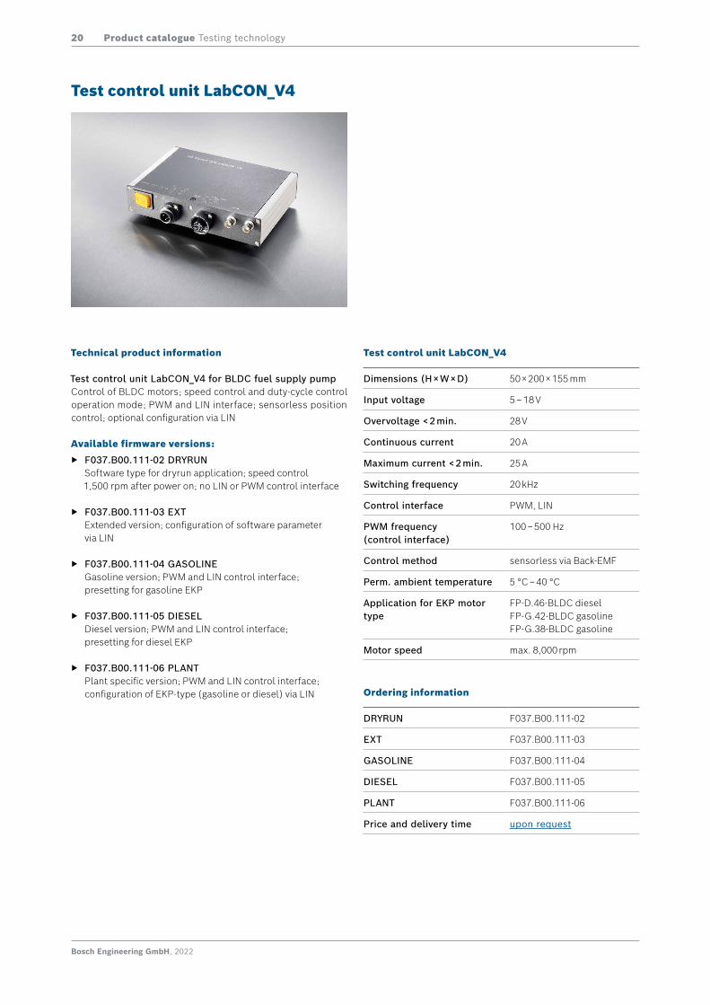
Technical product information
Test control unit LabCON_V4 for BLDC fuel supply pumpControl of BLDC motors; speed control and duty-cycle control operation mode; PWM and LIN interface; sensorless position control; optional configuration via LIN
Available firmware versions:
f F037.B00.111-02 DRYRUN Software type for dryrun application; speed control 1,500 rpm after power on; no LIN or PWM control interface
f F037.B00.111-03 EXT Extended version; configuration of software parameter via LIN
f F037.B00.111-04 GASOLINE Gasoline version; PWM and LIN control interface; presetting for gasoline EKP
f F037.B00.111-05 DIESEL Diesel version; PWM and LIN control interface; presetting for diesel EKP
f F037.B00.111-06 PLANT Plant specific version; PWM and LIN control interface; configuration of EKP-type (gasoline or diesel) via LIN
Test control unit LabCON_V4
Test control unit LabCON_V4
Dimensions (H × W × D) 50 × 200 × 155 mm
Input voltage 5 – 18 V
Overvoltage < 2 min. 28 V
Continuous current 20 A
Maximum current < 2 min. 25 A
Switching frequency 20 kHz
Control interface PWM, LIN
PWM frequency (control interface)
100 – 500 Hz
Control method sensorless via Back-EMF
Perm. ambient temperature 5 °C – 40 °C
Application for EKP motor type
FP-D.46-BLDC diesel FP-G.42-BLDC gasolineFP-G.38-BLDC gasoline
Motor speed max. 8,000 rpm
Ordering information
DRYRUN F037.B00.111-02
EXT F037.B00.111-03
GASOLINE F037.B00.111-04
DIESEL F037.B00.111-05
PLANT F037.B00.111-06
Price and delivery time upon request
Bosch Engineering GmbH, 2022
Product catalogue Testing technology21
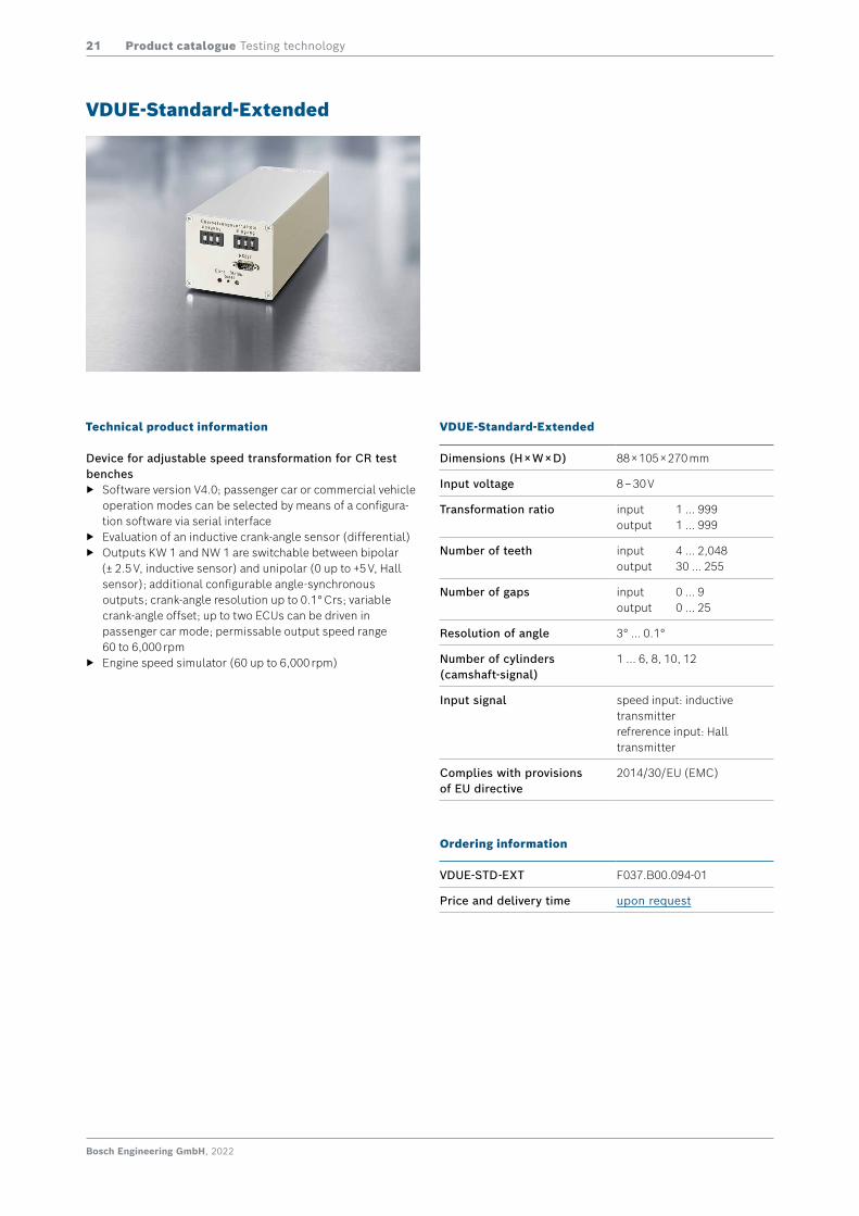
Technical product information
Device for adjustable speed transformation for CR test benches
f Software version V4.0; passenger car or commercial vehicle operation modes can be selected by means of a configura-tion software via serial interface
f Evaluation of an inductive crank-angle sensor (differential) f Outputs KW 1 and NW 1 are switchable between bipolar
(± 2.5 V, inductive sensor) and unipolar (0 up to +5 V, Hall sensor); additional configurable angle-synchronous outputs; crank-angle resolution up to 0.1° Crs; variable crank-angle offset; up to two ECUs can be driven in passenger car mode; permissable output speed range 60 to 6,000 rpm
f Engine speed simulator (60 up to 6,000 rpm)
VDUE-Standard-Extended
VDUE-Standard-Extended
Dimensions (H × W × D) 88 × 105 × 270 mm
Input voltage 8 – 30 V
Transformation ratio input 1 … 999output 1 … 999
Number of teeth input 4 … 2,048output 30 … 255
Number of gaps input 0 … 9output 0 … 25
Resolution of angle 3° … 0.1°
Number of cylinders (camshaft-signal)
1 … 6, 8, 10, 12
Input signal speed input: inductive transmitterrefrerence input: Hall transmitter
Complies with provisions of EU directive
2014/30/EU (EMC)
Ordering information
VDUE-STD-EXT F037.B00.094-01
Price and delivery time upon request
Bosch Engineering GmbH, 2022
Product catalogue Testing technology22
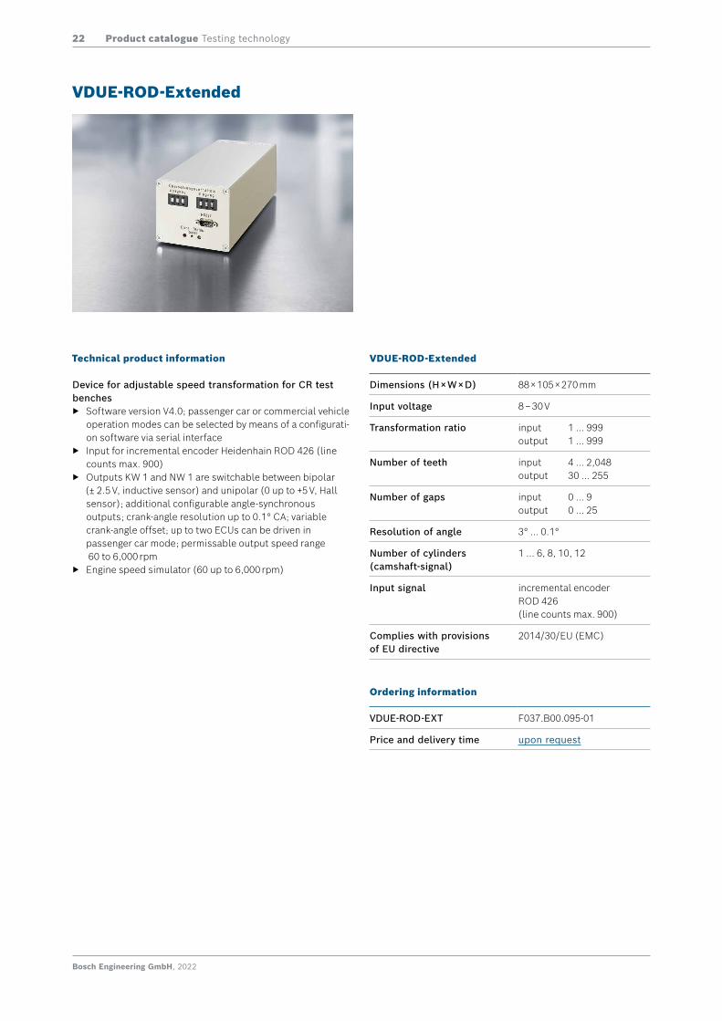
VDUE-ROD-Extended
Technical product information
Device for adjustable speed transformation for CR test benches
f Software version V4.0; passenger car or commercial vehicle operation modes can be selected by means of a configurati-on software via serial interface
f Input for incremental encoder Heidenhain ROD 426 (line counts max. 900)
f Outputs KW 1 and NW 1 are switchable between bipolar (± 2.5 V, inductive sensor) and unipolar (0 up to +5 V, Hall sensor); additional configurable angle-synchronous outputs; crank-angle resolution up to 0.1° CA; variable crank-angle offset; up to two ECUs can be driven in passenger car mode; permissable output speed range 60 to 6,000 rpm
f Engine speed simulator (60 up to 6,000 rpm)
VDUE-ROD-Extended
Dimensions (H × W × D) 88 × 105 × 270 mm
Input voltage 8 – 30 V
Transformation ratio input 1 … 999output 1 … 999
Number of teeth input 4 … 2,048output 30 … 255
Number of gaps input 0 … 9output 0 … 25
Resolution of angle 3° … 0.1°
Number of cylinders (camshaft-signal)
1 … 6, 8, 10, 12
Input signal incremental encoder ROD 426 (line counts max. 900)
Complies with provisions of EU directive
2014/30/EU (EMC)
Ordering information
VDUE-ROD-EXT F037.B00.095-01
Price and delivery time upon request
Bosch Engineering GmbH, 2022
Product catalogue Testing technology23
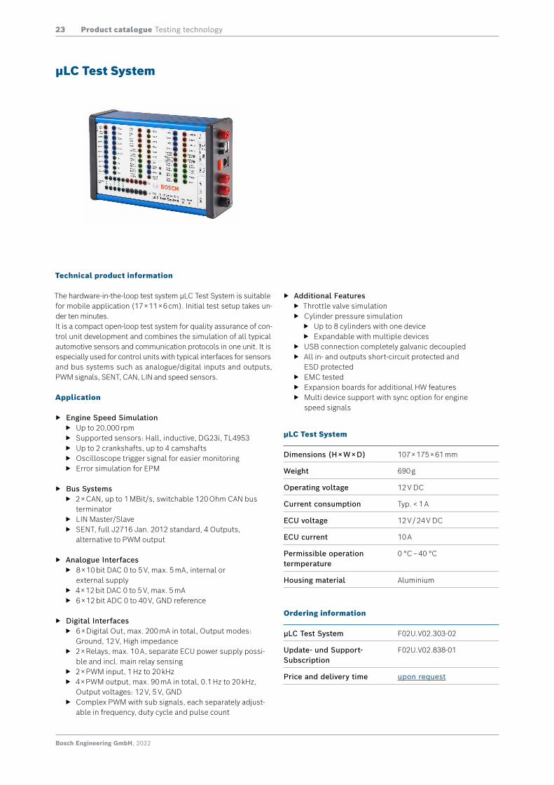
Technical product information
The hardware-in-the-loop test system μLC Test System is suitable for mobile application (17 × 11 × 6 cm). Initial test setup takes un-der ten minutes.It is a compact open-loop test system for quality assurance of con-trol unit development and combines the simulation of all typical automotive sensors and communication protocols in one unit. It is especially used for control units with typical interfaces for sensors and bus systems such as analogue/digital inputs and outputs, PWM signals, SENT, CAN, LIN and speed sensors.
Application
f Engine Speed Simulation f Up to 20,000 rpm f Supported sensors: Hall, inductive, DG23i, TL4953 f Up to 2 crankshafts, up to 4 camshafts f Oscilloscope trigger signal for easier monitoring f Error simulation for EPM
f Bus Systems f 2 × CAN, up to 1 MBit/s, switchable 120 Ohm CAN bus
terminator f LIN Master/Slave f SENT, full J2716 Jan. 2012 standard, 4 Outputs,
alternative to PWM output
f Analogue Interfaces f 8 × 10 bit DAC 0 to 5 V, max. 5 mA, internal or
external supply f 4 × 12 bit DAC 0 to 5 V, max. 5 mA f 6 × 12 bit ADC 0 to 40 V, GND reference
f Digital Interfaces f 6 × Digital Out, max. 200 mA in total, Output modes:
Ground, 12 V, High impedance f 2 × Relays, max. 10 A, separate ECU power supply possi-
ble and incl. main relay sensing f 2 × PWM input, 1 Hz to 20 kHz f 4 × PWM output, max. 90 mA in total, 0.1 Hz to 20 kHz,
Output voltages: 12 V, 5 V, GND f Complex PWM with sub signals, each separately adjust-
able in frequency, duty cycle and pulse count
µLC Test System
µLC Test System
Dimensions (H × W × D) 107 × 175 × 61 mm
Weight 690 g
Operating voltage 12 V DC
Current consumption Typ. < 1 A
ECU voltage 12 V / 24 V DC
ECU current 10 A
Permissible operation termperature
0 °C – 40 °C
Housing material Aluminium
Ordering information
µLC Test System F02U.V02.303-02
Update- und Support-Subscription
F02U.V02.838-01
Price and delivery time upon request
f Additional Features f Throttle valve simulation f Cylinder pressure simulation
f Up to 8 cylinders with one device f Expandable with multiple devices
f USB connection completely galvanic decoupled f All in- and outputs short-circuit protected and
ESD protected f EMC tested f Expansion boards for additional HW features f Multi device support with sync option for engine
speed signals
Bosch Engineering GmbH, 2022
Product catalogue Testing technology24
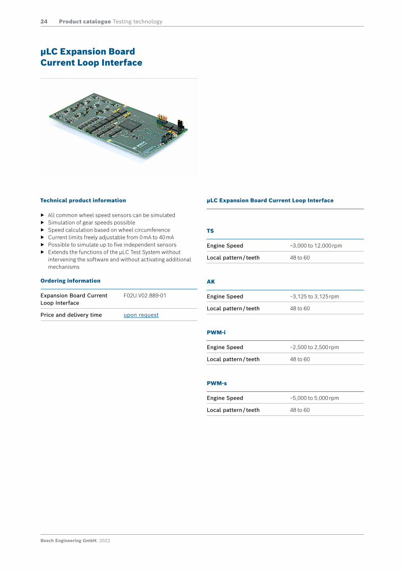
Technical product information
f All common wheel speed sensors can be simulated f Simulation of gear speeds possible f Speed calculation based on wheel circumference f Current limits freely adjustable from 0 mA to 40 mA f Possible to simulate up to five independent sensors f Extends the functions of the μLC Test System without
intervening the software and without activating additional mechanisms
µLC Expansion Board Current Loop Interface
µLC Expansion Board Current Loop Interface
TS
Engine Speed −3,000 to 12,000 rpm
Local pattern / teeth 48 to 60
AK
Engine Speed −3,125 to 3,125 rpm
Local pattern / teeth 48 to 60
PWM-i
Engine Speed −2,500 to 2,500 rpm
Local pattern / teeth 48 to 60
PWM-s
Engine Speed −5,000 to 5,000 rpm
Local pattern / teeth 48 to 60
Ordering information
Expansion Board CurrentLoop Interface
F02U.V02.889-01
Price and delivery time upon request
Bosch Engineering GmbH, 2022
Product catalogue Testing technology25
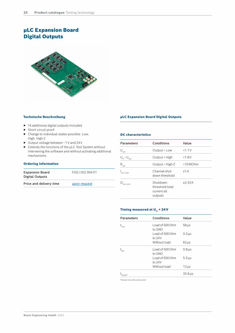
Technische Beschreibung
f 14 additional digital outputs included f Short circuit proof f Change to individual states possible: Low,
High, High-Z f Output voltage between −1 V and 24 V f Extends the functions of the μLC Test System without
intervening the software and without activating additional mechanisms
µLC Expansion BoardDigital Outputs
µLC Expansion Board Digital Outputs
DC characteristics
Parameters Conditions Value
Uout Output = Low <1.1 V
Uin – Uout Output = High <1.8 V
Rout Output = High-Z >10 MOhm
Iout, prot Channel shut-down threshold
±1 A
ΣIout, prot Shutdown threshold total current all outputs
±3.33 A
Timing measured at Uin = 24 V
Parameters Conditions Value
trise Load of 500 Ohm to GNDLoad of 500 Ohm to 24 VWithout load
58 μs
0.3 μs
62 μs
tfall Load of 500 Ohm to GNDLoad of 500 Ohm to 24 VWithout load
0.8 μs
5.5 μs
12 μs
trestart* 33.6 μs
Ordering information
Expansion BoardDigital Outputs
F02U.V02.904-01
Price and delivery time upon request
*Restart time after overcurrent
Bosch Engineering GmbH, 2022
Product catalogue Testing technology26
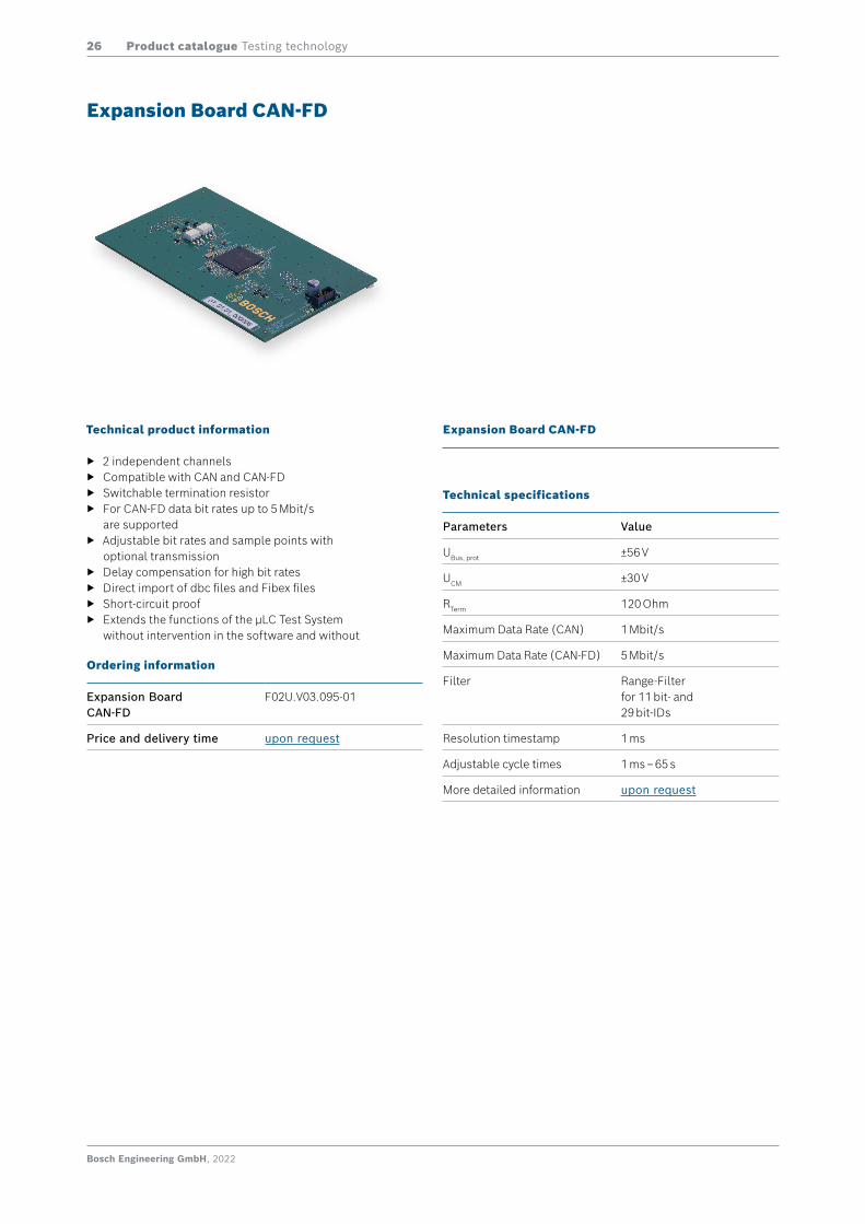
Technical product information
f 2 independent channels f Compatible with CAN and CAN-FD f Switchable termination resistor f For CAN-FD data bit rates up to 5 Mbit/s
are supported f Adjustable bit rates and sample points with
optional transmission f Delay compensation for high bit rates f Direct import of dbc files and Fibex files f Short-circuit proof f Extends the functions of the μLC Test System
without intervention in the software and without
Expansion Board CAN-FD
Ordering information
Expansion BoardCAN-FD
F02U.V03.095-01
Price and delivery time upon request
Expansion Board CAN-FD
Technical specifications
Parameters Value
UBus, prot ±56 V
UCM ±30 V
RTerm 120 Ohm
Maximum Data Rate (CAN) 1 Mbit/s
Maximum Data Rate (CAN-FD) 5 Mbit/s
Filter Range-Filterfor 11 bit- and29 bit-IDs
Resolution timestamp 1 ms
Adjustable cycle times 1 ms – 65 s
More detailed information upon request
Bosch Engineering GmbH, 2022
Product catalogue Testing technology27
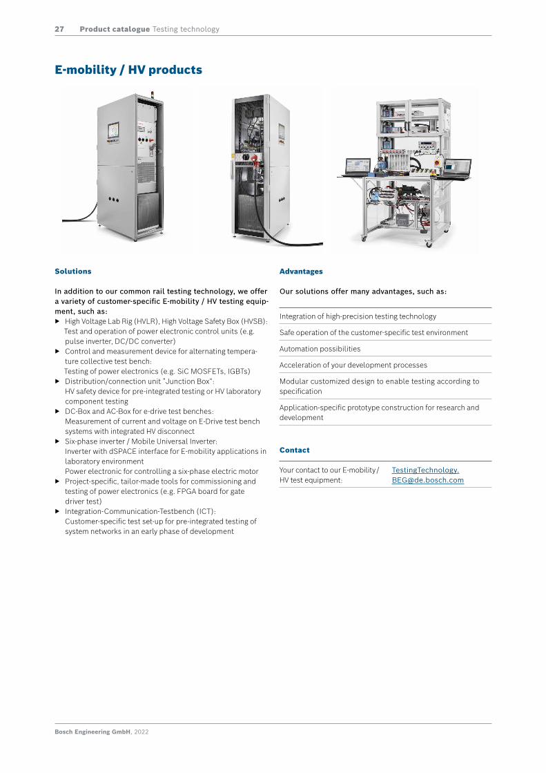
E-mobility / HV products
Integration of high-precision testing technology
Safe operation of the customer-specific test environment
Automation possibilities
Acceleration of your development processes
Modular customized design to enable testing according to specification
Application-specific prototype construction for research and development
Contact
Your contact to our E-mobility / HV test equipment:
Solutions
In addition to our common rail testing technology, we offer a variety of customer-specific E-mobility / HV testing equip-ment, such as:
f High Voltage Lab Rig (HVLR), High Voltage Safety Box (HVSB): Test and operation of power electronic control units (e.g. pulse inverter, DC/DC converter)
f Control and measurement device for alternating tempera-ture collective test bench: Testing of power electronics (e.g. SiC MOSFETs, IGBTs)
f Distribution/connection unit ”Junction Box“: HV safety device for pre-integrated testing or HV laboratory component testing
f DC-Box and AC-Box for e-drive test benches: Measurement of current and voltage on E-Drive test bench systems with integrated HV disconnect
f Six-phase inverter / Mobile Universal Inverter: Inverter with dSPACE interface for E-mobility applications in laboratory environment Power electronic for controlling a six-phase electric motor
f Project-specific, tailor-made tools for commissioning and testing of power electronics (e.g. FPGA board for gate driver test)
f Integration-Communication-Testbench (ICT): Customer-specific test set-up for pre-integrated testing of system networks in an early phase of development
Advantages
Our solutions offer many advantages, such as:
Bosch Engineering GmbH, 2022
Product catalogue Testing technology28
Accessories and spare parts
Technical product information Ordering information
IPC
IPC-201 Spare part wiring harness for CR test bench
f Wiring harness (set or single part) for operating an IPC-201 control unit on CR test benches
f Actuation of 2 CR actuators f Including system test and adapters
KBPB-IPC201-STD-SETKBPB-IPC201-STD-CON1/4KBPB-IPC201-CON2KBPB-IPC201-STD-CON3KBPB-IPC201-MH-SETKBPB-IPC201-MH-CON1/4KBPB-IPC201-MH-CON3
F037.B00.213-01F037.B00.214-01F037.B00.215-01F037.B00.216-01F037.B00.269-01F037.B00.270-01F037.B00.271-01
IPC-400Spare part wiring harness for CR test bench
f Wiring harness (set or single part) for operating an IPC-400 control unit on CR test benches
f Drive of 6 injectors f Including system test and standard-adapters; ad-
apter for CV-injectors can be ordered separately (F037.B00.204-01)
KBPB-IPC400-SET (CON1-4)KBPB-IPC400-CON1 KBPB-IPC400/450P-CON2KBPB-IPC400-CON3KBPB-IPC400-CON4
F037.B00.130-01F037.B00.122-01F037.B00.123-01F037.B00.124-01F037.B00.125-01
IPC-400 adapter set for CV injec-tors
f 6 piece; compact 1.1a Kod1 to contact claw M4 f For CV injectors with screw connection M4
KC-IPC NKW F037.B00.204-01
IPC-450P Spare part wiring har-ness for CR test bench
f Wiring harness (set or single part) for operating an IPC-450P control unit on CR test benches
f Drive of 6 piezo injectors f Including system test f Adapters can be ordered separately
KBPB-IPC450P-SET (CON1-4)KBPB-IPC450P-CON1KBPB-IPC400/450P-CON2KBPB-IPC450P-CON3KBPB-IPC450P-CON4
F037.B00.513-01F037.B00.514-01F037.B00.123-01F037.B00.515-01F037.B00.516-01
IPC-450P adap-ter set for injec-tor type 3.20
f 6 piece 2 pole Jetronic to compact1.1a, Kod. 1; Pin1 Pin1
f 6 piece 2 pole Jetronic to AK, latching 3, Kod. A; Pin1 Pin2
KC-IPC450P-SET 3.20 F037.B00.517-01
IPC-450P adap-ter set for high pressure
f 2 piece 2 pole Jetronic to compact 1.1a, Kod. 1 (DRV, ZME)
f 1 piece 2 pole compact 1.1 to AK; Kod. 1 latching 3; Kod. B (DRV)
f 1 piece 2 pole compact 1.1 to AK; Kod. 1 latching 3; Kod. A (ZME)
f 2 piece 3 pole Jetronic to AK, latching 3, Kod. A (RDS)
KC-IPC450P-SET HD F037.B00.518-01
IPC-450P adap-ter set for injec-tor type 3.27
f 6 piece 4 pole Jetronic, Binder to HMK Code A f 6 piece 4 pole Jetronic, Binder to HMK Code B
KC-IPC450P-SET 3.27 F037.B00.573-01
IPC-450P adapter set for injector type 3.20 incl. high pressure
f 1 piece IPC-450P adapter set for injector type 3.20 f 1 piece IPC-450P adapter set for high pressure
KC-IPC450P-SET 3.20 + HD F037.B00.572-01
IPC-450P adap-ter set complete
f 1 piece IPC-450P adapter set for injector type 3.20 f 1 piece IPC-450P adapter set for high pressure f 1 piece IPC-450P adapter set for injector type 3.27
KC-IPC450P-SET Gesamt F037.B00.574-01
µLC
Expansion Boards
Current Loop InterfaceDigital OutputsCAN-FD
F02U.V02.889-01 F02U.V02.904-01F02U.V03.095-01
Bosch Engineering GmbH, 2022
Product catalogue Testing technology29
Update service (upon request)
Technical product information Ordering information
HW update VDUE
Adaptation of passenger car/commercial vehicle/EMI equipment to extended function
f Adaptation of passenger car/commercial vehicle/EMI equipment to extended function; hardware version (standard/ROD) unchanged
f Including configuration software f After adaptation all extended features can be applied
(see VDUE-STD-EXT or VDUE-ROD-EXT)
MOD-VDUE
Adaptation of equipment with extended function to V4.0
f Adaptation of equipment with extended function to extended function V4.0; hardware version (standard/ROD) unchanged
f Including configuration software V4.0
MOD-VDUE4.0
HW-Update IPC-400
Adaptation to CE construction
f Adaptation of devices without CE state of construction (F037.B00.121-01) to devices with CE state of construction
MOD-IPC400CE
µLC Software Options
Update- und Support- Subscription
F02U.V02.838-01
30 Produktkatalog / Product catalogue Mess- und Prüftechnik / Testing technology
Technischer Vertrieb / Technical salesJonathan BöttgerBEG/EME4Telephone +49(8024)[email protected]
Produktmanager / Product managerWolfgang HennerBEG/EME4Telephone +49(8024)[email protected]
Technische Kundenbetreuung / Technical [email protected]
Disponent / Material plannerRainer SchmalbergerBEG/EME4Telephone +49(8024)[email protected]
Peter BaumgartnerBEG/EME4Telephone +49(8024)[email protected]
Auftragsabwicklung / Order [email protected]
Auftragsabwicklung / Order administration µLC Test [email protected]
Unsere KontaktpersonenOur contact persons
Bosch Engineering GmbH | BEG/EME4 | Bergfeldstraße 2 | 83607 Holzkirchen | Deutschland | www.bosch-engineering.com/de/portfolio/testing/mess-und-prueftechnik/