Embed Size (px)
Citation preview
KTH Engineering Sciences
Residual Stress Analysis and Fatigue Assessment of Welded Steel Structures
Zuheir Barsoum
Doctoral Thesis
Stockholm, Sweden 2008
Division of Lightweight Structures
Department of Aeronautical and Vehicle Engineering
School of Engineering Sciences
Kungliga Tekniska Högskolan
Department of Aeronautical and Vehicle Engineering Kungliga Tekniska Högskolan (KTH) SE-100 44 Stockholm Academic dissertation which with permission of Kungliga Tekniska Högskolan in Stockholm is presented for public review and doctoral examination on April 25th 2008 at 10.00 in E1, KTH, Lindstedtsvägen 3, Stockholm. TRITA-AVE 2008:11 ISSN 1651-7660 © Zuheir Barsoum, 2008.
PREFACE The work in this doctoral thesis has been carried out at the Division of Lightweight Structures at the Department of Aeronautical and Vehicle Engineering at KTH between September 2003 and April 2008. The work done in this thesis is a part of the Nordic R&D project QFAB - Quality and Cost of Fabricated Advanced Welded Structures which was brought to conclusion in 2006. The research was continued in the Swedish R&D project LOST - Light Optimized Welded Structures, which was started in 2007. Some of the work has also been presented and discussed within Commission XIII (Fatigue of Welded Structures) in the International Institute of Welding (IIW) during the Annual Assembly in Prague 2005, Quebec 2006 and Dubrovnik 2007. The work in this thesis has been funded by Volvo Construction Equipment (Volvo CE), SSAB, The Swedish Vehicle Research Program (PFF), the Nordic Innovation Centre (NiCe), VINNOVA and the MERA program. First and foremost, I would like to express my sincere gratitude to my supervisor, Prof. Jack Samuelsson (Volvo CE and KTH), for his continued support, encouragement and patience throughout the process of this work. His guidance as a scientist, mentor and friend is greatly appreciated. Mr. Mats Gustafsson at SSAB, with whom I have been working during the research project is also acknowledged. I would also like to thank the people within the Division of Lightweight Structures. Special thanks are also due to Tekn. Lic. Anders Björkblad, Dr. Johan Martinsson, Prof. Dan Zenkert and Mr. Bo Magnusson. Thank you Mr. Sohrab Kazemahvazi for valuable discussions about research, mountain biking and for never getting tiered of my endless questions. Thank you Tekn. Lic. Markus Kaufmann for always helping me with computer problems. Prof. Lars-Erik Lindgren and Tekn. Lic. Andreas Lundbäck, at Luleå University of Technology is acknowledged for valuable discussion on welding simulation and residual stress measurements. I am also grateful to the staff within Volvo Group for their co-operation during the span of this work e.g. Mr. Bertil Jonsson, Tekn. Lic. Magnus Byggnevi, Dr. Fethi Abdulwahab, Mr. Mirsattar Hejazifar, Mr. Nenad Mrden, Mr. Franjo Jakopovic and Mr. Kjell Eriksson. Special and hearty thanks go to my twin brother Dr. Imad Barsoum at the Department of Solid Mechanics (KTH) who I have had the pleasure to work with and write one of the papers within this thesis. Thank you also for being a friend, a brother and a mentor from my very first day in this world. To Gina, Carla, Abbe and Amelin et al. just to mention a few of you and not being long-winded; thank you for a solid friendship, I know that it will last for a lifetime! Last but not least, I am forever grateful to Nadira and Samir, my mother and father, Fadi, my younger brother, for their unconditional love and support. God bless you! Stockholm, February 2008
Zuheir Barsoum

i
ii
ABSTRACT This doctoral thesis is concerned with fatigue life of welded structures. Several topics related to fatigue of welded structures are treated such as; weld defects and their influence on fatigue performance of welded structures, fatigue life prediction using LEFM (Linear Elastic Fracture Mechanics), fatigue testing, welding simulation, residual stress prediction and measurement and their influence on fatigue life. The work that is reported in this doctoral thesis is part results of a Nordic R&D project QFAB (Quality and Cost of Fabricated Advanced Welded Structures) and a Swedish R&D project LOST (Light Optimized Welded Structures). One of the main objectives is to compare different welding processes with respect to fatigue performance and gain understanding of the weld defects, their appearance for different welding processes and their influence on fatigue life. Another main objective is to study welding residual stresses and their effect on fatigue. Fatigue design rules are in some cases conservative and further knowledge about the residual stress field, especially on the weld root side, may improve the accuracy of life prediction calculations. The aim is to develop simplified procedures for analysis of residual stresses, their relaxation and influence on fatigue life. Fatigue testing of Hybrid Nd: YAG laser/MAG and MAG welded (tandem arc solid wire, flux cored wire, tandem flux cored wire) non-load carrying cruciform joints was carried out. Four batches were produced, tested and the results were compared. The local weld geometry of the cruciform welded joints was measured and analyzed. Residual stress measurement was carried out close to the toe region using X-ray diffraction. Weld defects, in most cases cold laps, in the cracked specimens were measured. Further fatigue testing, weld defect assessment and residual stress and local weld geometry measurements were carried out on joints welded with flux cored and metal cored arc wires. Two-and three dimensional LEFM crack growth analysis was carried out in order to assess the influence of weld defects, local weld geometry and residual stresses. Residual stresses in multi-pass welded tube-to-plates were studied for two different tubular joint configurations; a three-pass single-U weld groove for maximum weld penetration and a two-pass fillet (no groove) weld for minimum weld penetration. Torsion fatigue tests were performed in order to study crack propagation from the weld root. Mode III propagation from the lower and upper weld toe on the same tubular joints was also studied. Some tubes were stress relieved (PWHT) and some were fatigue tested with internal static pressure. A three dimensional finite element welding simulation of the multi-pass welded tubular joint was carried out. The calculated temperatures in the transient thermal analysis were compared with measured temperatures. The FE predicted residual stresses in the as-welded conditions were verified with hole drilling strain gage measurements. The residual stresses were used as internal stresses in the finite element model for the torsion fatigue simulation in order to study the cycle by cycle relaxation of the residual stresses in constant amplitude torsion loading. A two dimensional finite element welding simulation procedure was developed in order to predict welding residual stress. These were used together with a developed 2D LEFM subroutine to predict the fatigue life, crack path and the effect of residual stresses on weld root defects. The developed simulation subroutines were verified with results found in the literature. Residual stresses measurement and two-and three dimensional welding simulations were carried out in fillet welded joints in order to study the three dimensional effects of the welding process, boundary conditions and modelling technique on the formation of residual stresses.
i

iii
iv
APPENDED PAPERS Paper A Barsoum Z. and Samuelsson J., Fatigue Assessment of Cruciform Joints Welded with Different Methods, published in Steel Research International, Vol.77, No.12, 2006 This paper was also presented and discussed within Commission XIII (Fatigue of Welded Structures) in the International Institute of Welding (IIW) during the annual assembly, Prague 2005. Paper B Barsoum Z. and Jonsson B., Fatigue Assessment and LEFM Analysis of Cruciform Joints Fabricated with Different Welding Processes, accepted for publication in Welding in the World, 2007. This paper was also presented and discussed within Commission XIII (Fatigue of Welded Structures) in the International Institute of Welding (IIW) during the annual assembly, Dubrovnik, Croatia, 2007. Paper C Barsoum Z., Residual Stress Analysis and Fatigue of Multi-pass Welded Tubular Structures, published in Engineering Failure Analysis, article in press, 2008. This paper was also presented and discussed within Commission XIII (Fatigue of Welded Structures) in the International Institute of Welding (IIW) during the annual assembly, Prague 2005. Paper D Barsoum Z. and Samuelsson J., Residual Stress Prediction and Relaxation in Welded Tubular Joint, published in Welding in the World, Vol. 51, Issue 1/2, 2007. This paper was also presented and discussed within Commission XIII (Fatigue of Welded Structures) in the International Institute of Welding (IIW) during the annual assembly, Quebec City, Canada, 2006. Paper E Barsoum Z. and Barsoum I., Residual stress effect on fatigue life of welded structures using LEFM, submitted for publication, 2008. Paper F Barsoum Z. and Lundbäck A., FEM welding simulation of fillet welds – 3D effects on residual stresses, to be submitted for publication, 2008.
ii

v
vi
PAPERS NOT INCLUDED IN THIS THESIS Barsoum Z. and Gustafsson M., Spectrum Fatigue of High Strength Steel Joints Welded with Low Temperature Transformation Consumables, Presented at 2nd International Conference on Fatigue Design, Senlis, France, 2007. DIVISION OF WORK BETWEEN AUTHORS Paper A Z. Barsoum carried out fatigue testing, measurements, defect detection, evaluating results, planned the work and wrote the paper. J. Samuelsson contributed to the paper with valuable comments and discussion. Paper B Z. Barsoum carried out fatigue testing, measurements, defect detection, evaluating results, FEM analysis, fracture mechanical analysis, planned the work and wrote the paper. B. Jonsson carried out the 3D fracture mechanics analysis. Paper E Z. Barsoum developed the FE subroutines for; welding simulations, LEFM automatic simulation of fatigue crack propagation. Z. Barsoum also carried out the validation, implementation of the developed subroutine on a welded structure, planned the work and wrote the paper. I. Barsoum contributed with the remeshing algorithm. Paper F Z. Barsoum carried out the 2D welding simulations in Ansys and assisted in the 3D welding simulations. Z. Barsoum planned the simulation work, measurements, fabrication of specimen and wrote the paper. A. Lundbäck carried out the welding simulations in Marc and contributed to the writing of the paper.
iii

vii
viii
CONTENTS ABSTRACT............................................................................................................................... .i APPENDED PAPERS ............................................................................................................... ii PAPERS NOT INCLUDED IN THIS THESIS........................................................................ iii DIVISION OF WORK BETWEEN AUTHORS...................................................................... iii CONTENTS.............................................................................................................................. iv INTRODUCTION...................................................................................................................... 1
Background ............................................................................................................................ 1 Research aim .......................................................................................................................... 3 Research approach.................................................................................................................. 3
FATIGUE LIFE ASSESSMENT............................................................................................... 4 Fatigue testing ........................................................................................................................ 5 Effective notch stress method ................................................................................................ 5 Linear elastic fracture mechanics (LEFM)............................................................................. 8 Mixed mode crack growth.................................................................................................... 10
WELD DEFECTS .................................................................................................................... 13 HEAT EFFECTS OF WELDING............................................................................................ 15
Thermal modelling and simulation ...................................................................................... 16 Welding residual stresses ..................................................................................................... 20 Finite element modelling of welding residual stresses......................................................... 20 Material modelling ............................................................................................................... 21
RESIDUAL STRESS MEASUREMENT TECHNIQUES ..................................................... 22 RESIDUAL STRESS EFFECT ON FATIGUE OF WELDS.................................................. 23
Effect of external loading..................................................................................................... 24 Effect on crack propagation ................................................................................................. 25
DISCUSSION .......................................................................................................................... 28 CONCLUSIONS...................................................................................................................... 29 SUGGESTION FOR FUTURE WORK .................................................................................. 30 SUMMARY OF APPENDED PAPERS.................................................................................. 30 REFERENCES......................................................................................................................... 31
iv

Z. Barsoum Residual Stress Analysis and Fatigue Assessment of Welded Steel Structures
1
INTRODUCTION
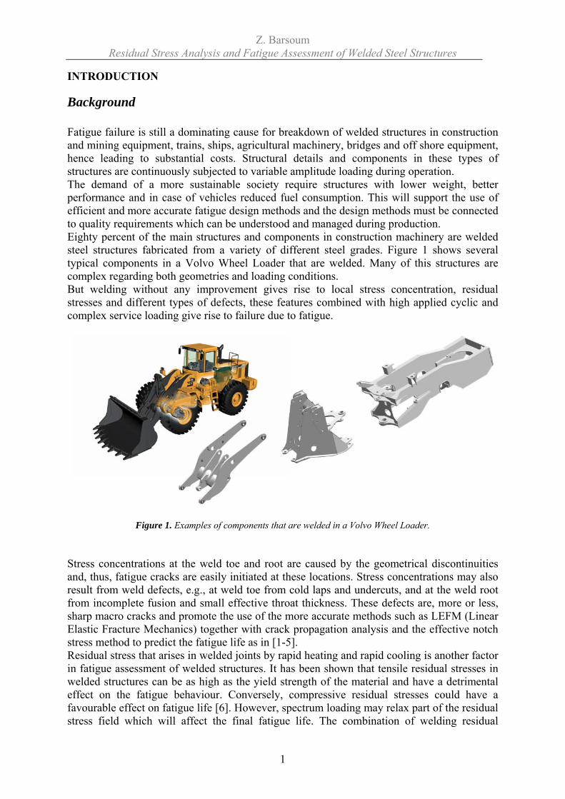
Background Fatigue failure is still a dominating cause for breakdown of welded structures in construction and mining equipment, trains, ships, agricultural machinery, bridges and off shore equipment, hence leading to substantial costs. Structural details and components in these types of structures are continuously subjected to variable amplitude loading during operation. The demand of a more sustainable society require structures with lower weight, better performance and in case of vehicles reduced fuel consumption. This will support the use of efficient and more accurate fatigue design methods and the design methods must be connected to quality requirements which can be understood and managed during production. Eighty percent of the main structures and components in construction machinery are welded steel structures fabricated from a variety of different steel grades. Figure 1 shows several typical components in a Volvo Wheel Loader that are welded. Many of this structures are complex regarding both geometries and loading conditions. But welding without any improvement gives rise to local stress concentration, residual stresses and different types of defects, these features combined with high applied cyclic and complex service loading give rise to failure due to fatigue.
Figure 1. Examples of components that are welded in a Volvo Wheel Loader. Stress concentrations at the weld toe and root are caused by the geometrical discontinuities and, thus, fatigue cracks are easily initiated at these locations. Stress concentrations may also result from weld defects, e.g., at weld toe from cold laps and undercuts, and at the weld root from incomplete fusion and small effective throat thickness. These defects are, more or less, sharp macro cracks and promote the use of the more accurate methods such as LEFM (Linear Elastic Fracture Mechanics) together with crack propagation analysis and the effective notch stress method to predict the fatigue life as in [1-5]. Residual stress that arises in welded joints by rapid heating and rapid cooling is another factor in fatigue assessment of welded structures. It has been shown that tensile residual stresses in welded structures can be as high as the yield strength of the material and have a detrimental effect on the fatigue behaviour. Conversely, compressive residual stresses could have a favourable effect on fatigue life [6]. However, spectrum loading may relax part of the residual stress field which will affect the final fatigue life. The combination of welding residual
Z. Barsoum Residual Stress Analysis and Fatigue Assessment of Welded Steel Structures
2
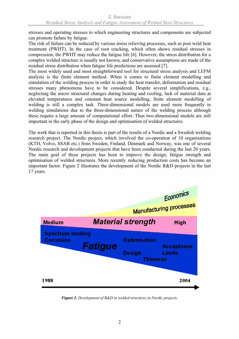
stresses and operating stresses to which engineering structures and components are subjected can promote failure by fatigue. The risk of failure can be reduced by various stress relieving processes, such as post weld heat treatment (PWHT). In the case of root cracking, which often shows residual stresses in compression, the PWHT may reduce the fatigue life [6]. However, the stress distribution for a complex welded structure is usually not known, and conservative assumptions are made of the residual stress distribution when fatigue life predictions are assessed [7]. The most widely used and most straightforward tool for structural stress analysis and LEFM analysis is the finite element method. When it comes to finite element modelling and simulation of the welding process in order to study the heat transfer, deformation and residual stresses many phenomena have to be considered. Despite several simplifications, e.g., neglecting the micro structural changes during heating and cooling, lack of material data at elevated temperatures and constant heat source modelling, finite element modelling of welding is still a complex task. Three-dimensional models are used more frequently in welding simulations due to the three-dimensional nature of the welding process although these require a large amount of computational effort. Thus two-dimensional models are still important in the early phase of the design and optimisation of welded structures. The work that is reported in this thesis is part of the results of a Nordic and a Swedish welding research project. The Nordic project, which involved the co-operation of 10 organisations (KTH, Volvo, SSAB etc.) from Sweden, Finland, Denmark and Norway, was one of several Nordic research and development projects that have been conducted during the last 20 years. The main goal of these projects has been to improve the design, fatigue strength and optimisation of welded structures. More recently reducing production costs has become an important factor. Figure 2 illustrates the development of the Nordic R&D projects in the last 17 years.
Figure 2. Development of R&D in welded structures in Nordic projects.
Z. Barsoum Residual Stress Analysis and Fatigue Assessment of Welded Steel Structures
3
The Nordic project QFAB - Quality and Cost of Fabricated Advanced Welded Structures was completed in 2006. An international symposium was held in 2007 for the presentation of the results from the QFAB-project [8]. The primary aim of this project was to reduce production costs by fabricating components using high speed/deposition rate welding processes without producing components which will be more sensitive to failure by fatigue. To achieve the technical objectives, the programme of work has been divided into nine work packages (WP). WP1 - High-speed Welding Process Development and Defect Detection – focuses on the economic benefits of high productivity processes, innovation in the form of novel arc welding techniques, consumables and increase in welding speed and deposition rate. For fatigue sensitive components, it is equally important that an acceptable weld bead profile is produced without forming toe defects especially cold laps. The welding processes investigated were be based on the tandem arc process which uses two wires instead of the conventional single wire process to achieve high welding speeds and high deposition rates. WP5 - Residual Stress Prediction – gives attention to welding residual stresses and their effect on fatigue. Design rules are, in most cases, conservative. Especially for fatigue assessment of the weld root better knowledge about the residual stress field may improve the accuracy of fatigue life predictions. In former Nordic R&D projects, many of the case studies were related to weld root problems and the actual residual stress distribution was known in only a few cases. In this work package the aim was to develop welding simulation procedures and also predict and measure residual stress distributions. Effects of the welding residual stress will be incorporated in the fatigue assessments of analyzed welds by local approaches i.e. LEFM. The research within this doctoral thesis was continued in the Swedish R&D-project LOST - Light Optimized Welded Structures.
Research aim The research work in this doctoral thesis aims to increase the accuracy of fatigue design of welded steel structures. More specifically, the research question(s) and issues addressed are:
Establishing a link between weld quality and fatigue life.
Improved engineering methods for prediction of welding residual stresses.
Incorporation of residual stresses into fatigue design methods.
Research approach The research can be divided in four different items: 1. Fatigue assessment – testing and fatigue life prediction. Manufacture of cruciform joint test pieces for fatigue testing, in order to compare the performance of different welding methods with respect to fatigue resistance. Manufacture of tubular joint test pieces in order to study torsion fatigue and Mode III crack growth. Finally,
Z. Barsoum Residual Stress Analysis and Fatigue Assessment of Welded Steel Structures
4
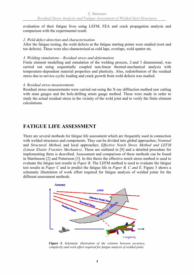
evaluation of their fatigue lives using LEFM, FEA and crack propagation analysis and comparison with the experimental result. 2. Weld defect detection and characterisation. After the fatigue testing, the weld defects at the fatigue starting points were studied (root and toe defects). These were also characterised as cold laps, overlaps, weld spatter etc. 3. Welding simulations – Residual stress and deformation. Finite element modelling and simulation of the welding process, 2-and 3 dimensional, was carried out using sequentially coupled non-linear thermal-mechanical analysis with temperature-dependent material properties and plasticity. Also, redistribution of the residual stress due to service cyclic loading and crack growth from weld defects was studied. 4. Residual stress measurements. Residual stress measurements were carried out using the X-ray diffraction method saw cutting with stain gauges and the hole-drilling strain gauge method. These were made in order to study the actual residual stress in the vicinity of the weld joint and to verify the finite element calculations. FATIGUE LIFE ASSESSMENT There are several methods for fatigue life assessment which are frequently used in connection with welded structures and components. They can be divided into global approaches; Nominal and Structural Method, and local approaches; Effective Notch Stress Method and LEFM (Linear Elastic Fracture Mechanics). These are outlined in [9] and a detailed procedure for implementing them is described. Assessment and comparison of these methods can be found in Martinsson [2] and Pettersson [3]. In this thesis the effective notch stress method is used to evaluate the fatigue test results in Paper B. The LEFM method is used to evaluate the fatigue test results in Paper C and to predict the fatigue life in Paper B, C and E. Figure 3 shows a schematic illustration of work effort required for fatigue analysis of welded joints for the different assessment methods.
Figure 3. Schematic illustration of the relation between accuracy, complexity and work effort required for fatigue analysis of welded joints.
Z. Barsoum Residual Stress Analysis and Fatigue Assessment of Welded Steel Structures
5
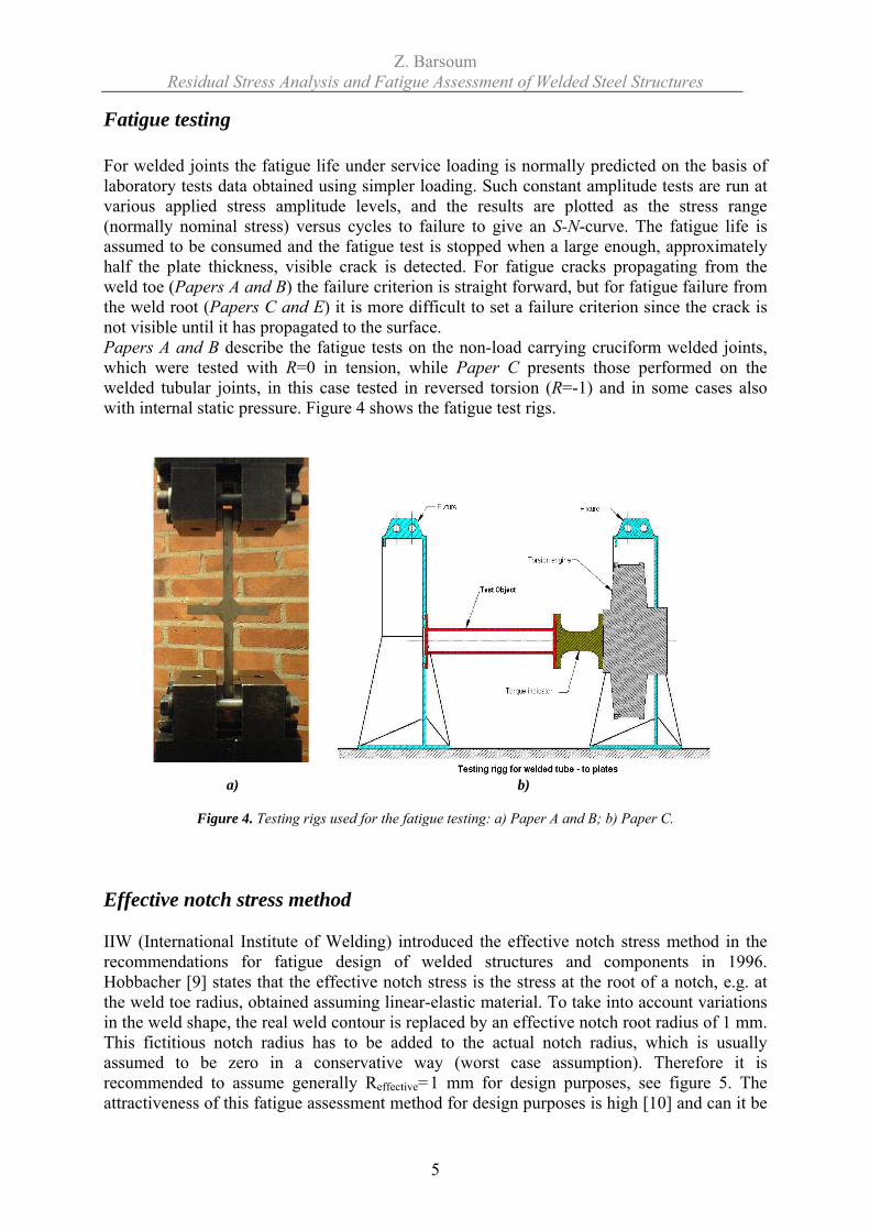
Fatigue testing For welded joints the fatigue life under service loading is normally predicted on the basis of laboratory tests data obtained using simpler loading. Such constant amplitude tests are run at various applied stress amplitude levels, and the results are plotted as the stress range (normally nominal stress) versus cycles to failure to give an S-N-curve. The fatigue life is assumed to be consumed and the fatigue test is stopped when a large enough, approximately half the plate thickness, visible crack is detected. For fatigue cracks propagating from the weld toe (Papers A and B) the failure criterion is straight forward, but for fatigue failure from the weld root (Papers C and E) it is more difficult to set a failure criterion since the crack is not visible until it has propagated to the surface. Papers A and B describe the fatigue tests on the non-load carrying cruciform welded joints, which were tested with R=0 in tension, while Paper C presents those performed on the welded tubular joints, in this case tested in reversed torsion (R=-1) and in some cases also with internal static pressure. Figure 4 shows the fatigue test rigs.
a) b)
Figure 4. Testing rigs used for the fatigue testing: a) Paper A and B; b) Paper C.
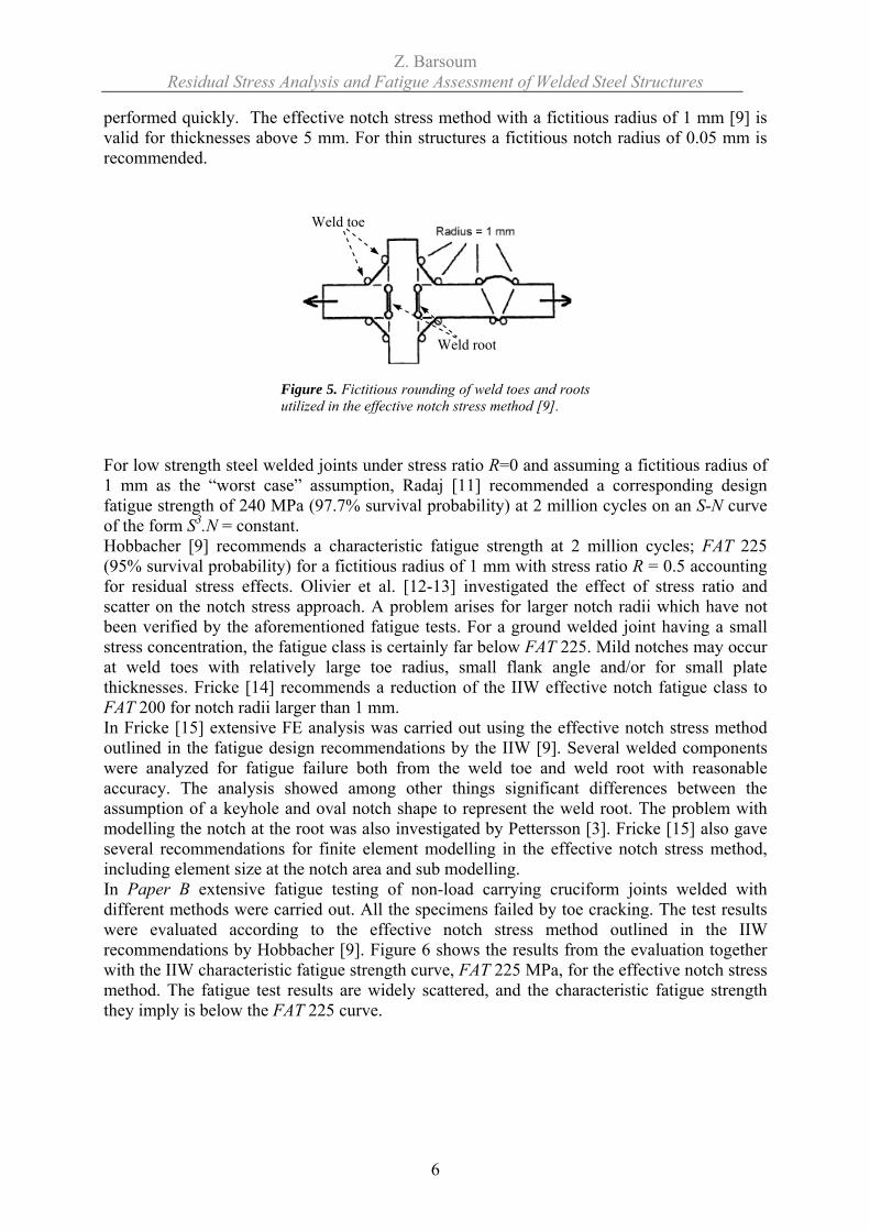
Effective notch stress method IIW (International Institute of Welding) introduced the effective notch stress method in the recommendations for fatigue design of welded structures and components in 1996. Hobbacher [9] states that the effective notch stress is the stress at the root of a notch, e.g. at the weld toe radius, obtained assuming linear-elastic material. To take into account variations in the weld shape, the real weld contour is replaced by an effective notch root radius of 1 mm. This fictitious notch radius has to be added to the actual notch radius, which is usually assumed to be zero in a conservative way (worst case assumption). Therefore it is recommended to assume generally Reffective=1 mm for design purposes, see figure 5. The attractiveness of this fatigue assessment method for design purposes is high [10] and can it be
Z. Barsoum Residual Stress Analysis and Fatigue Assessment of Welded Steel Structures
6
performed quickly. The effective notch stress method with a fictitious radius of 1 mm [9] is valid for thicknesses above 5 mm. For thin structures a fictitious notch radius of 0.05 mm is recommended.
Figure 5. Fictitious rounding of weld toes and roots utilized in the effective notch stress method [9].
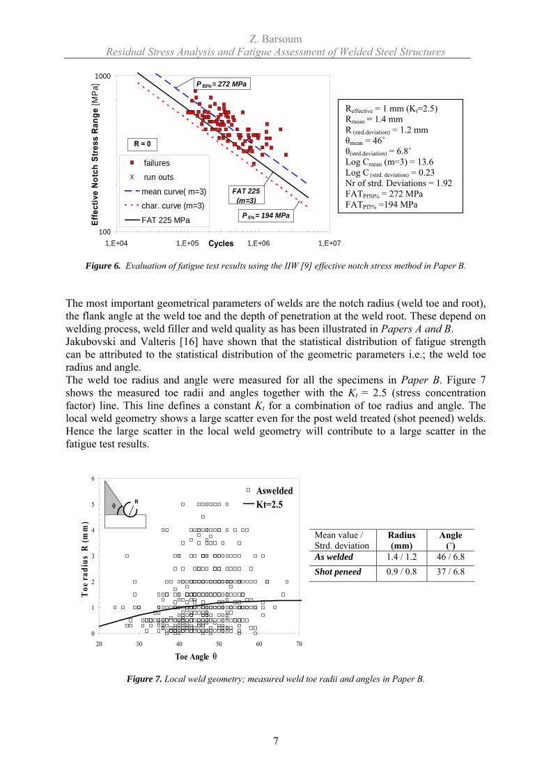
For low strength steel welded joints under stress ratio R=0 and assuming a fictitious radius of 1 mm as the “worst case” assumption, Radaj [11] recommended a corresponding design fatigue strength of 240 MPa (97.7% survival probability) at 2 million cycles on an S-N curve of the form S3.N = constant. Hobbacher [9] recommends a characteristic fatigue strength at 2 million cycles; FAT 225 (95% survival probability) for a fictitious radius of 1 mm with stress ratio R = 0.5 accounting for residual stress effects. Olivier et al. [12-13] investigated the effect of stress ratio and scatter on the notch stress approach. A problem arises for larger notch radii which have not been verified by the aforementioned fatigue tests. For a ground welded joint having a small stress concentration, the fatigue class is certainly far below FAT 225. Mild notches may occur at weld toes with relatively large toe radius, small flank angle and/or for small plate thicknesses. Fricke [14] recommends a reduction of the IIW effective notch fatigue class to FAT 200 for notch radii larger than 1 mm. In Fricke [15] extensive FE analysis was carried out using the effective notch stress method outlined in the fatigue design recommendations by the IIW [9]. Several welded components were analyzed for fatigue failure both from the weld toe and weld root with reasonable accuracy. The analysis showed among other things significant differences between the assumption of a keyhole and oval notch shape to represent the weld root. The problem with modelling the notch at the root was also investigated by Pettersson [3]. Fricke [15] also gave several recommendations for finite element modelling in the effective notch stress method, including element size at the notch area and sub modelling. In Paper B extensive fatigue testing of non-load carrying cruciform joints welded with different methods were carried out. All the specimens failed by toe cracking. The test results were evaluated according to the effective notch stress method outlined in the IIW recommendations by Hobbacher [9]. Figure 6 shows the results from the evaluation together with the IIW characteristic fatigue strength curve, FAT 225 MPa, for the effective notch stress method. The fatigue test results are widely scattered, and the characteristic fatigue strength they imply is below the FAT 225 curve.
Weld toe
Weld root
Z. Barsoum Residual Stress Analysis and Fatigue Assessment of Welded Steel Structures
7
Figure 6. Evaluation of fatigue test results using the IIW [9] effective notch stress method in Paper B.
The most important geometrical parameters of welds are the notch radius (weld toe and root), the flank angle at the weld toe and the depth of penetration at the weld root. These depend on welding process, weld filler and weld quality as has been illustrated in Papers A and B. Jakubovski and Valteris [16] have shown that the statistical distribution of fatigue strength can be attributed to the statistical distribution of the geometric parameters i.e.; the weld toe radius and angle. The weld toe radius and angle were measured for all the specimens in Paper B. Figure 7 shows the measured toe radii and angles together with the Kt = 2.5 (stress concentration factor) line. This line defines a constant Kt for a combination of toe radius and angle. The local weld geometry shows a large scatter even for the post weld treated (shot peened) welds. Hence the large scatter in the local weld geometry will contribute to a large scatter in the fatigue test results.
0
1
2
3
4
5
6
20 30 40 50 60 70
Toe Angle θ
Toe
rad
ius
R (m
m)
AsweldedKt=2.5R
θ
Mean value / Strd. deviation
Radius (mm)
Angle (˚)
As welded 1.4 / 1.2 46 / 6.8 Shot peneed 0.9 / 0.8 37 / 6.8
Figure 7. Local weld geometry; measured weld toe radii and angles in Paper B.
Reffective = 1 mm (Kt=2.5) Rmean = 1.4 mm R (strd.deviation) = 1.2 mm θmean = 46˚ θ(strd.deviation) = 6.8˚ Log Cmean (m=3) = 13.6 Log C (strd. deviation) = 0.23 Nr of strd. Deviations = 1.92 FATPf50% = 272 MPa FATPf5% =194 MPa
100
1000
1,E+04 1,E+05 1,E+06 1,E+07Cycles
Effe
ctiv
e N
otch
Str
ess
Ran
ge [M
Pa]
failures
run outs
mean curve( m=3)
char. curve (m=3)
FAT 225 MPa P 5%= 194 MPa
FAT 225(m=3)
P 50%= 272 MPa
R = 0
Z. Barsoum Residual Stress Analysis and Fatigue Assessment of Welded Steel Structures
8
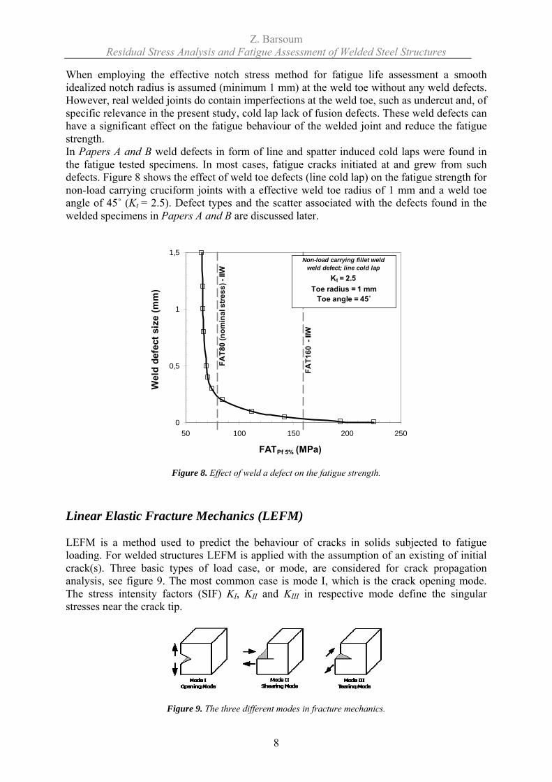
When employing the effective notch stress method for fatigue life assessment a smooth idealized notch radius is assumed (minimum 1 mm) at the weld toe without any weld defects. However, real welded joints do contain imperfections at the weld toe, such as undercut and, of specific relevance in the present study, cold lap lack of fusion defects. These weld defects can have a significant effect on the fatigue behaviour of the welded joint and reduce the fatigue strength. In Papers A and B weld defects in form of line and spatter induced cold laps were found in the fatigue tested specimens. In most cases, fatigue cracks initiated at and grew from such defects. Figure 8 shows the effect of weld toe defects (line cold lap) on the fatigue strength for non-load carrying cruciform joints with a effective weld toe radius of 1 mm and a weld toe angle of 45˚ (Kt = 2.5). Defect types and the scatter associated with the defects found in the welded specimens in Papers A and B are discussed later.
0
0,5
1
1,5
50 100 150 200 250
FATPf 5% (MPa)
Wel
d de
fect
siz
e (m
m)
FA
T80
(nom
inal
stre
ss) -
IIW
FA
T160
- II
W
Non-load carrying fillet weld weld defect; line cold lap
Kt = 2.5Toe radius = 1 mm
Toe angle = 45˚
Figure 8. Effect of weld a defect on the fatigue strength. Linear Elastic Fracture Mechanics (LEFM) LEFM is a method used to predict the behaviour of cracks in solids subjected to fatigue loading. For welded structures LEFM is applied with the assumption of an existing of initial crack(s). Three basic types of load case, or mode, are considered for crack propagation analysis, see figure 9. The most common case is mode I, which is the crack opening mode. The stress intensity factors (SIF) KI, KII and KIII in respective mode define the singular stresses near the crack tip.
Figure 9. The three different modes in fracture mechanics.
Z. Barsoum Residual Stress Analysis and Fatigue Assessment of Welded Steel Structures
9
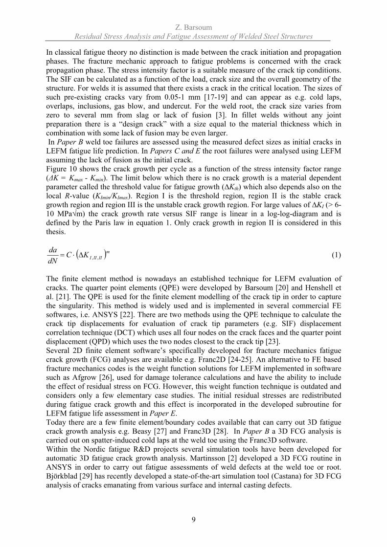
In classical fatigue theory no distinction is made between the crack initiation and propagation phases. The fracture mechanic approach to fatigue problems is concerned with the crack propagation phase. The stress intensity factor is a suitable measure of the crack tip conditions. The SIF can be calculated as a function of the load, crack size and the overall geometry of the structure. For welds it is assumed that there exists a crack in the critical location. The sizes of such pre-existing cracks vary from 0.05-1 mm [17-19] and can appear as e.g. cold laps, overlaps, inclusions, gas blow, and undercut. For the weld root, the crack size varies from zero to several mm from slag or lack of fusion [3]. In fillet welds without any joint preparation there is a “design crack” with a size equal to the material thickness which in combination with some lack of fusion may be even larger. In Paper B weld toe failures are assessed using the measured defect sizes as initial cracks in LEFM fatigue life prediction. In Papers C and E the root failures were analysed using LEFM assuming the lack of fusion as the initial crack. Figure 10 shows the crack growth per cycle as a function of the stress intensity factor range (ΔK = Kmax - Kmin). The limit below which there is no crack growth is a material dependent parameter called the threshold value for fatigue growth (∆Kth) which also depends also on the local R-value (KImin/KImax). Region I is the threshold region, region II is the stable crack growth region and region III is the unstable crack growth region. For large values of ∆KI (> 6-10 MPa√m) the crack growth rate versus SIF range is linear in a log-log-diagram and is defined by the Paris law in equation 1. Only crack growth in region II is considered in this thesis.
( )mIIIIIKC
dNda
,,Δ⋅= (1)
The finite element method is nowadays an established technique for LEFM evaluation of cracks. The quarter point elements (QPE) were developed by Barsoum [20] and Henshell et al. [21]. The QPE is used for the finite element modelling of the crack tip in order to capture the singularity. This method is widely used and is implemented in several commercial FE softwares, i.e. ANSYS [22]. There are two methods using the QPE technique to calculate the crack tip displacements for evaluation of crack tip parameters (e.g. SIF) displacement correlation technique (DCT) which uses all four nodes on the crack faces and the quarter point displacement (QPD) which uses the two nodes closest to the crack tip [23]. Several 2D finite element software’s specifically developed for fracture mechanics fatigue crack growth (FCG) analyses are available e.g. Franc2D [24-25]. An alternative to FE based fracture mechanics codes is the weight function solutions for LEFM implemented in software such as Afgrow [26], used for damage tolerance calculations and have the ability to include the effect of residual stress on FCG. However, this weight function technique is outdated and considers only a few elementary case studies. The initial residual stresses are redistributed during fatigue crack growth and this effect is incorporated in the developed subroutine for LEFM fatigue life assessment in Paper E. Today there are a few finite element/boundary codes available that can carry out 3D fatigue crack growth analysis e.g. Beasy [27] and Franc3D [28]. In Paper B a 3D FCG analysis is carried out on spatter-induced cold laps at the weld toe using the Franc3D software. Within the Nordic fatigue R&D projects several simulation tools have been developed for automatic 3D fatigue crack growth analysis. Martinsson [2] developed a 3D FCG routine in ANSYS in order to carry out fatigue assessments of weld defects at the weld toe or root. Björkblad [29] has recently developed a state-of-the-art simulation tool (Castana) for 3D FCG analysis of cracks emanating from various surface and internal casting defects.
Z. Barsoum Residual Stress Analysis and Fatigue Assessment of Welded Steel Structures
10
Figure 10. Principal features of the crack growth law.
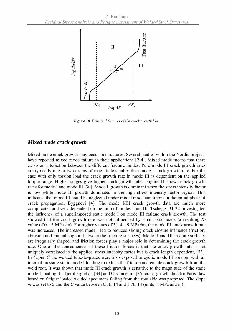
Mixed mode crack growth Mixed mode crack growth may occur in structures. Several studies within the Nordic projects have reported mixed mode failure in their applications [2-4]. Mixed mode means that there exists an interaction between the different fracture modes. Pure mode III crack growth rates are typically one or two orders of magnitude smaller than mode I crack growth rate. For the case with only torsion load the crack growth rate in mode III is dependent on the applied torque range. Higher ranges give higher crack growth rates. Figure 11 shows crack growth rates for mode I and mode III [30]. Mode I growth is dominant when the stress intensity factor is low while mode III growth dominates in the high stress intensity factor region. This indicates that mode III could be neglected under mixed mode conditions in the initial phase of crack propagation, Byggnevi [4]. The mode I/III crack growth data are much more complicated and very dependent on the ratio of modes I and III. Tschegg [31-32] investigated the influence of a superimposed static mode I on mode III fatigue crack growth. The test showed that the crack growth rate was not influenced by small axial loads (a resulting KI value of 0 – 3 MPa√m). For higher values of KI, 4 – 9 MPa√m, the mode III crack growth rate was increased. The increased mode I led to reduced sliding crack closure influence (friction, abrasion and mutual support between the fracture surfaces). Mode II and III fracture surfaces are irregularly shaped, and friction forces play a major role in determining the crack growth rate. One of the consequences of these friction forces is that the crack growth rate is not uniquely correlated to the applied stress intensity factor but is crack-length dependent, [33]. In Paper C the welded tube-to-plates were also exposed to cyclic mode III torsion, with an internal pressure static mode I loading to reduce the friction and enable crack growth from the weld root. It was shown that mode III crack growth is sensitive to the magnitude of the static mode I loading. In Tjernberg et al. [34] and Olsson et al. [35] crack growth data for Paris’ law based on fatigue loaded welded specimens failing from the root side was proposed. The slope m was set to 5 and the C value between 0.7E-14 and 1.7E-14 (units in MPa and m).
log
da/d
N
log ΔK
I
II
III
1 m
ΔKc ΔKth
Thre
shol
d
Fast
frac
ture
Z. Barsoum Residual Stress Analysis and Fatigue Assessment of Welded Steel Structures
11
Figure 11. Crack growth rates for mode I and III, [4].
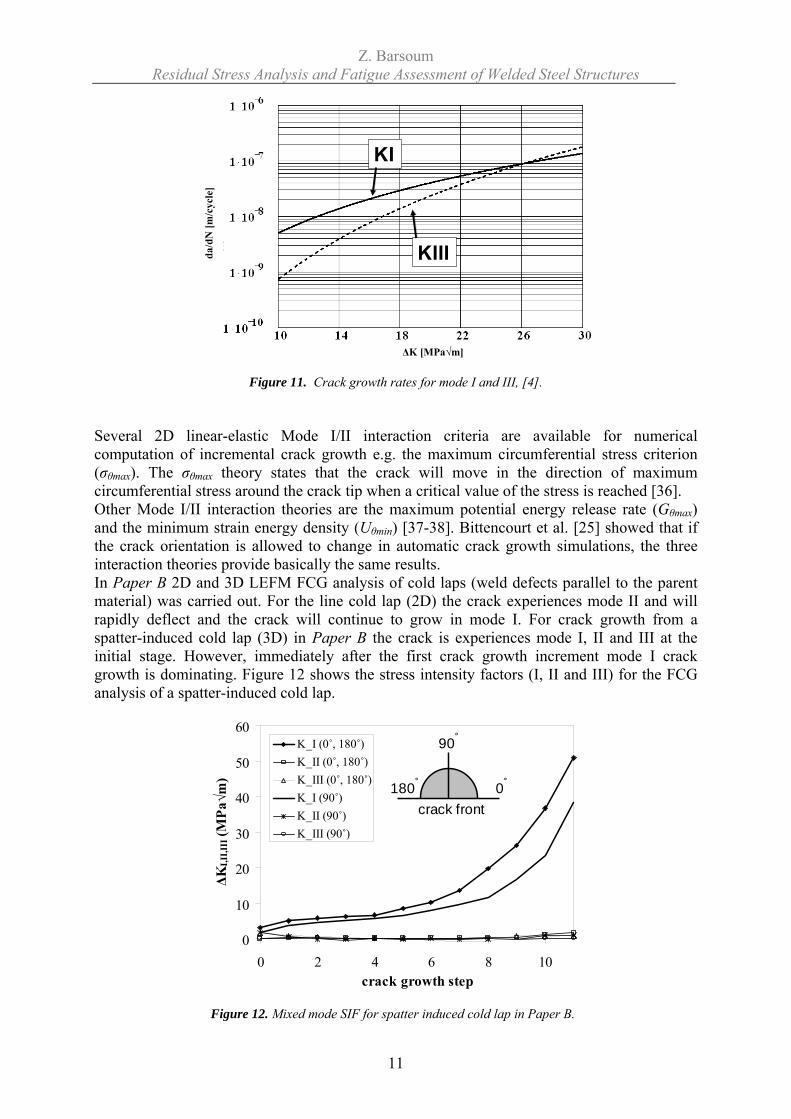
Several 2D linear-elastic Mode I/II interaction criteria are available for numerical computation of incremental crack growth e.g. the maximum circumferential stress criterion (σθmax). The σθmax theory states that the crack will move in the direction of maximum circumferential stress around the crack tip when a critical value of the stress is reached [36]. Other Mode I/II interaction theories are the maximum potential energy release rate (Gθmax) and the minimum strain energy density (Uθmin) [37-38]. Bittencourt et al. [25] showed that if the crack orientation is allowed to change in automatic crack growth simulations, the three interaction theories provide basically the same results. In Paper B 2D and 3D LEFM FCG analysis of cold laps (weld defects parallel to the parent material) was carried out. For the line cold lap (2D) the crack experiences mode II and will rapidly deflect and the crack will continue to grow in mode I. For crack growth from a spatter-induced cold lap (3D) in Paper B the crack is experiences mode I, II and III at the initial stage. However, immediately after the first crack growth increment mode I crack growth is dominating. Figure 12 shows the stress intensity factors (I, II and III) for the FCG analysis of a spatter-induced cold lap.
0
10
20
30
40
50
60
0 2 4 6 8 10crack growth step
ΔKI,I
I,III
(MPa
√m)
K_I (0˚, 180˚)K_II (0˚, 180˚)K_III (0˚, 180˚)K_I (90˚)K_II (90˚)K_III (90˚)
0˚
90˚
180˚
crack front
Figure 12. Mixed mode SIF for spatter induced cold lap in Paper B.
da/d
N [m
/cyc
le]
e
KI
KIIIe
KI
KIII
ΔK [MPa√m]
Z. Barsoum Residual Stress Analysis and Fatigue Assessment of Welded Steel Structures
12
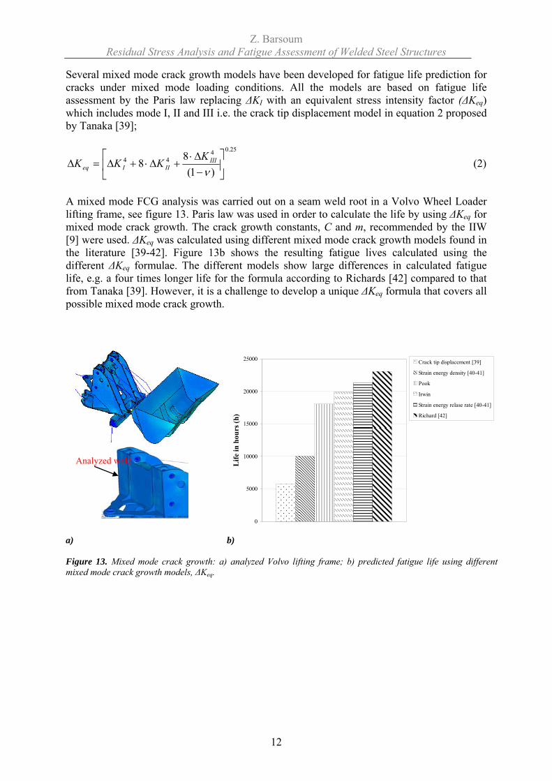
Several mixed mode crack growth models have been developed for fatigue life prediction for cracks under mixed mode loading conditions. All the models are based on fatigue life assessment by the Paris law replacing ΔKI with an equivalent stress intensity factor (ΔKeq) which includes mode I, II and III i.e. the crack tip displacement model in equation 2 proposed by Tanaka [39];
25.0444
)1(88 ⎥
⎦
⎤⎢⎣
⎡−Δ⋅
+Δ⋅+Δ=Δν
IIIIIIeq
KKKK (2)
A mixed mode FCG analysis was carried out on a seam weld root in a Volvo Wheel Loader lifting frame, see figure 13. Paris law was used in order to calculate the life by using ΔKeq for mixed mode crack growth. The crack growth constants, C and m, recommended by the IIW [9] were used. ΔKeq was calculated using different mixed mode crack growth models found in the literature [39-42]. Figure 13b shows the resulting fatigue lives calculated using the different ΔKeq formulae. The different models show large differences in calculated fatigue life, e.g. a four times longer life for the formula according to Richards [42] compared to that from Tanaka [39]. However, it is a challenge to develop a unique ΔKeq formula that covers all possible mixed mode crack growth.
0
5000
10000
15000
20000
25000
Life
in h
ours
(h)
Crack tip displacement [39]
Strain energy density [40-41]
Pook
Irwin
Strain energy relase rate [40-41]
Richard [42]
a) b) Figure 13. Mixed mode crack growth: a) analyzed Volvo lifting frame; b) predicted fatigue life using different mixed mode crack growth models, ΔKeq.
Analyzed weld
Z. Barsoum Residual Stress Analysis and Fatigue Assessment of Welded Steel Structures
13
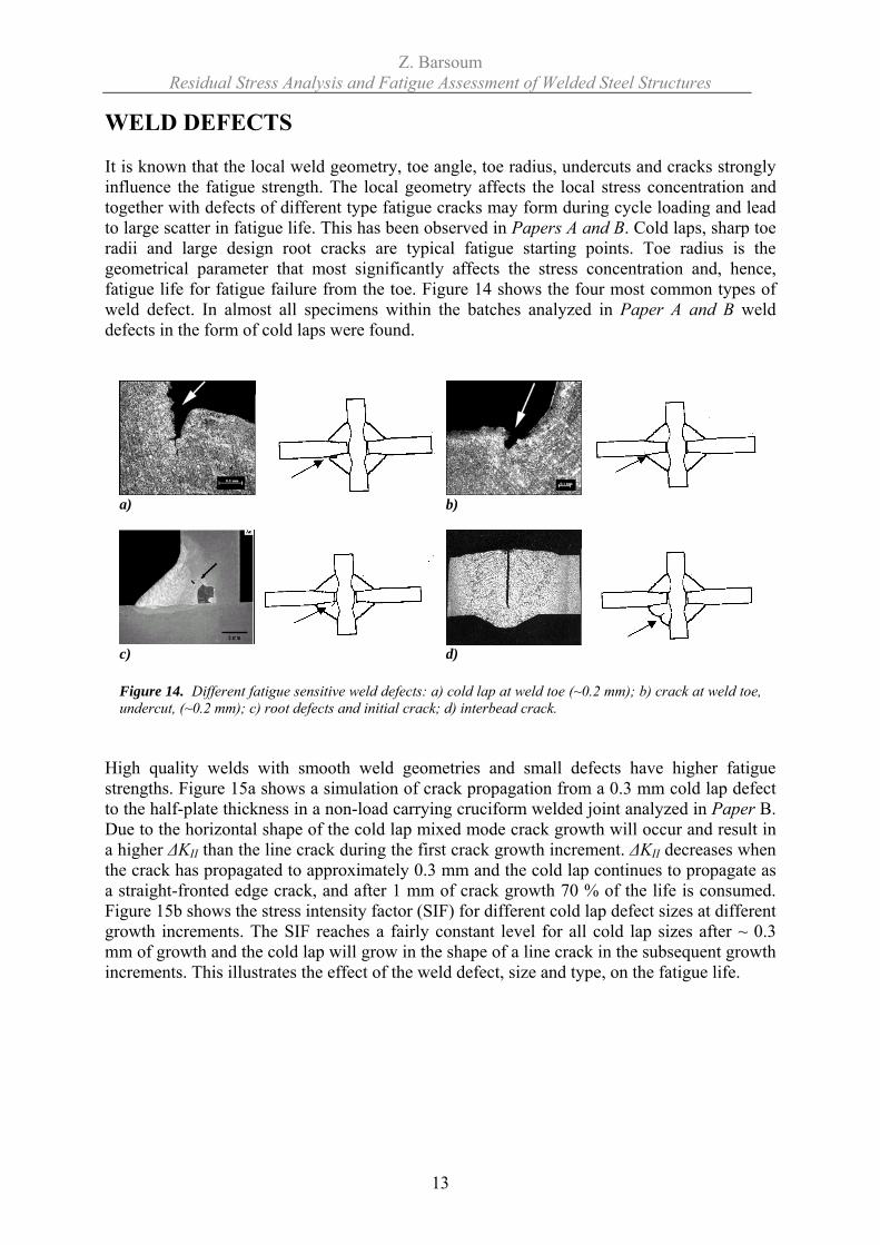
WELD DEFECTS It is known that the local weld geometry, toe angle, toe radius, undercuts and cracks strongly influence the fatigue strength. The local geometry affects the local stress concentration and together with defects of different type fatigue cracks may form during cycle loading and lead to large scatter in fatigue life. This has been observed in Papers A and B. Cold laps, sharp toe radii and large design root cracks are typical fatigue starting points. Toe radius is the geometrical parameter that most significantly affects the stress concentration and, hence, fatigue life for fatigue failure from the toe. Figure 14 shows the four most common types of weld defect. In almost all specimens within the batches analyzed in Paper A and B weld defects in the form of cold laps were found.
a) b)
c) d) Figure 14. Different fatigue sensitive weld defects: a) cold lap at weld toe (~0.2 mm); b) crack at weld toe, undercut, (~0.2 mm); c) root defects and initial crack; d) interbead crack.
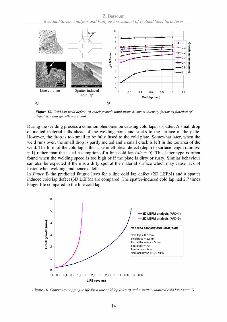
High quality welds with smooth weld geometries and small defects have higher fatigue strengths. Figure 15a shows a simulation of crack propagation from a 0.3 mm cold lap defect to the half-plate thickness in a non-load carrying cruciform welded joint analyzed in Paper B. Due to the horizontal shape of the cold lap mixed mode crack growth will occur and result in a higher ΔKII than the line crack during the first crack growth increment. ΔKII decreases when the crack has propagated to approximately 0.3 mm and the cold lap continues to propagate as a straight-fronted edge crack, and after 1 mm of crack growth 70 % of the life is consumed. Figure 15b shows the stress intensity factor (SIF) for different cold lap defect sizes at different growth increments. The SIF reaches a fairly constant level for all cold lap sizes after ~ 0.3 mm of growth and the cold lap will grow in the shape of a line crack in the subsequent growth increments. This illustrates the effect of the weld defect, size and type, on the fatigue life.
Z. Barsoum Residual Stress Analysis and Fatigue Assessment of Welded Steel Structures
14
0
1
2
3
4
5
6
7
8
9
10
0 0,2 0,4 0,6 0,8 1 1,2
Cold lap (mm)
ΔK
MPa
√m
0
0.1
0.2
0.3
0.4
0.5
1
Grow
th increment (m
m)
a) b) Figure 15. Cold lap weld defect: a) crack growth simulation; b) stress intensity factor as function of defect size and growth increment.
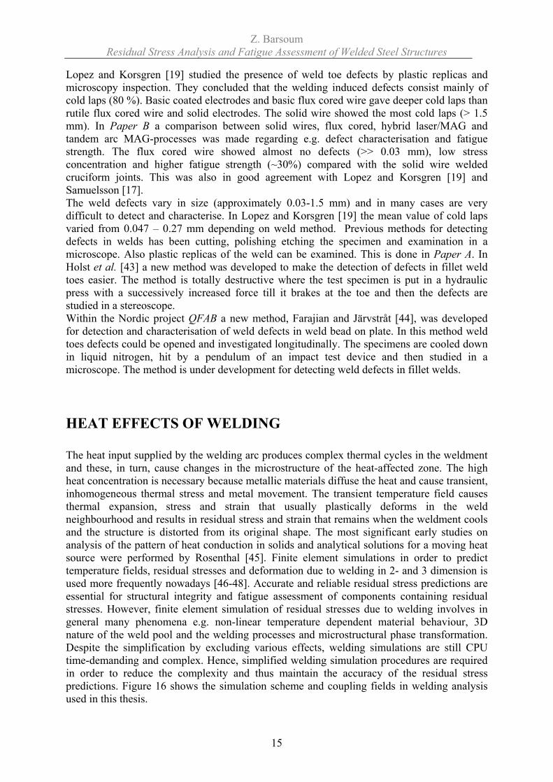
During the welding process a common phenomenon causing cold laps is spatter. A small drop of melted material falls ahead of the welding point and sticks to the surface of the plate. However, the drop is too small to be fully fused to the cold plate. Somewhat later, when the weld runs over, the small drop is partly melted and a small crack is left in the toe area of the weld. The form of the cold lap is thus a semi elliptical defect (depth to surface length ratio a/c = 1) rather than the usual assumption of a line cold lap (a/c = 0). This latter type is often found when the welding speed is too high or if the plate is dirty or rusty. Similar behaviour can also be expected if there is a dirty spot at the material surface which may cause lack of fusion when welding, and hence a defect. In Paper B the predicted fatigue lives for a line cold lap defect (2D LEFM) and a spatter induced cold lap defect (3D LEFM) are compared. The spatter-induced cold lap had 2.7 times longer life compared to the line cold lap.
0
1
2
3
4
5
6
0,E+00 5,E+05 1,E+06 2,E+06 2,E+06 3,E+06 3,E+06
LIFE (cycles)
Cra
ck g
row
th (m
m)
3D LEFM analysis (A/C=1)2D LEFM analysis (A/C=0)
Non load carrying cruciform joint:
Cold lap = 0.2 mmThickness = 12 mmThroat thickness = 5 mmToe angle = 70˚Toe radius = 0 mmNominal stress = 100 MPa
Figure 16. Comparison of fatigue life for a line cold lap (a/c=0) and a spatter- induced cold lap (a/c = 1).
failure
Line cold lap Spatter induced cold lap
Z. Barsoum Residual Stress Analysis and Fatigue Assessment of Welded Steel Structures
15
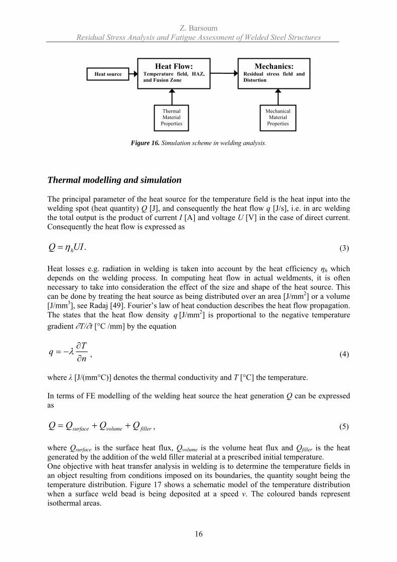
Lopez and Korsgren [19] studied the presence of weld toe defects by plastic replicas and microscopy inspection. They concluded that the welding induced defects consist mainly of cold laps (80 %). Basic coated electrodes and basic flux cored wire gave deeper cold laps than rutile flux cored wire and solid electrodes. The solid wire showed the most cold laps (> 1.5 mm). In Paper B a comparison between solid wires, flux cored, hybrid laser/MAG and tandem arc MAG-processes was made regarding e.g. defect characterisation and fatigue strength. The flux cored wire showed almost no defects (>> 0.03 mm), low stress concentration and higher fatigue strength (~30%) compared with the solid wire welded cruciform joints. This was also in good agreement with Lopez and Korsgren [19] and Samuelsson [17]. The weld defects vary in size (approximately 0.03-1.5 mm) and in many cases are very difficult to detect and characterise. In Lopez and Korsgren [19] the mean value of cold laps varied from 0.047 – 0.27 mm depending on weld method. Previous methods for detecting defects in welds has been cutting, polishing etching the specimen and examination in a microscope. Also plastic replicas of the weld can be examined. This is done in Paper A. In Holst et al. [43] a new method was developed to make the detection of defects in fillet weld toes easier. The method is totally destructive where the test specimen is put in a hydraulic press with a successively increased force till it brakes at the toe and then the defects are studied in a stereoscope. Within the Nordic project QFAB a new method, Farajian and Järvstråt [44], was developed for detection and characterisation of weld defects in weld bead on plate. In this method weld toes defects could be opened and investigated longitudinally. The specimens are cooled down in liquid nitrogen, hit by a pendulum of an impact test device and then studied in a microscope. The method is under development for detecting weld defects in fillet welds. HEAT EFFECTS OF WELDING The heat input supplied by the welding arc produces complex thermal cycles in the weldment and these, in turn, cause changes in the microstructure of the heat-affected zone. The high heat concentration is necessary because metallic materials diffuse the heat and cause transient, inhomogeneous thermal stress and metal movement. The transient temperature field causes thermal expansion, stress and strain that usually plastically deforms in the weld neighbourhood and results in residual stress and strain that remains when the weldment cools and the structure is distorted from its original shape. The most significant early studies on analysis of the pattern of heat conduction in solids and analytical solutions for a moving heat source were performed by Rosenthal [45]. Finite element simulations in order to predict temperature fields, residual stresses and deformation due to welding in 2- and 3 dimension is used more frequently nowadays [46-48]. Accurate and reliable residual stress predictions are essential for structural integrity and fatigue assessment of components containing residual stresses. However, finite element simulation of residual stresses due to welding involves in general many phenomena e.g. non-linear temperature dependent material behaviour, 3D nature of the weld pool and the welding processes and microstructural phase transformation. Despite the simplification by excluding various effects, welding simulations are still CPU time-demanding and complex. Hence, simplified welding simulation procedures are required in order to reduce the complexity and thus maintain the accuracy of the residual stress predictions. Figure 16 shows the simulation scheme and coupling fields in welding analysis used in this thesis.
Z. Barsoum Residual Stress Analysis and Fatigue Assessment of Welded Steel Structures
16
Figure 16. Simulation scheme in welding analysis. Thermal modelling and simulation The principal parameter of the heat source for the temperature field is the heat input into the welding spot (heat quantity) Q [J], and consequently the heat flow q [J/s], i.e. in arc welding the total output is the product of current I [A] and voltage U [V] in the case of direct current. Consequently the heat flow is expressed as
.UIQ hη= (3)
Heat losses e.g. radiation in welding is taken into account by the heat efficiency ηh which depends on the welding process. In computing heat flow in actual weldments, it is often necessary to take into consideration the effect of the size and shape of the heat source. This can be done by treating the heat source as being distributed over an area [J/mm2] or a volume [J/mm3], see Radaj [49]. Fourier’s law of heat conduction describes the heat flow propagation. The states that the heat flow density q [J/mm2] is proportional to the negative temperature gradient ∂T/∂t [°C /mm] by the equation
nTq
∂∂
−= λ , (4)
where λ [J/(mm°C)] denotes the thermal conductivity and T [°C] the temperature. In terms of FE modelling of the welding heat source the heat generation Q can be expressed as
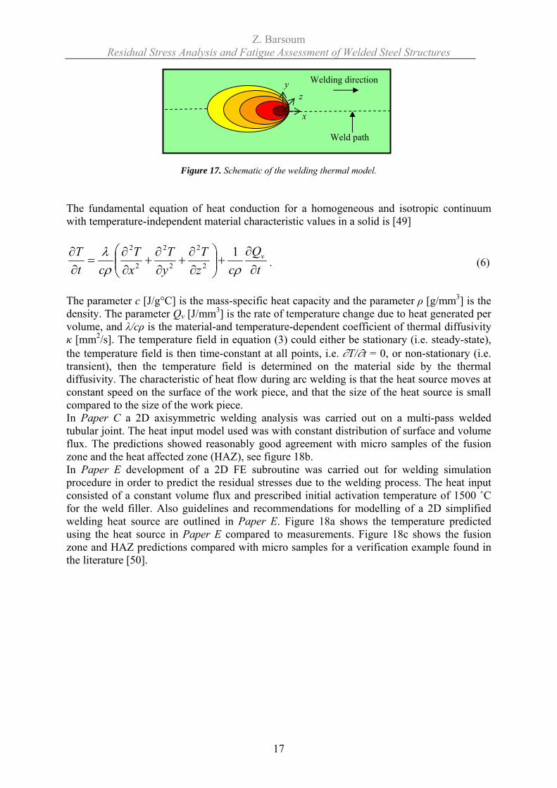
fillervolumesurface QQQQ ++= , (5) where Qsurface is the surface heat flux, Qvolume is the volume heat flux and Qfiller is the heat generated by the addition of the weld filler material at a prescribed initial temperature. One objective with heat transfer analysis in welding is to determine the temperature fields in an object resulting from conditions imposed on its boundaries, the quantity sought being the temperature distribution. Figure 17 shows a schematic model of the temperature distribution when a surface weld bead is being deposited at a speed v. The coloured bands represent isothermal areas.
Heat Flow: Temperature field, HAZ, and Fusion Zone
Mechanics: Residual stress field and Distortion
Thermal Material
Properties
Mechanical Material
Properties
Heat source
Z. Barsoum Residual Stress Analysis and Fatigue Assessment of Welded Steel Structures
17
Figure 17. Schematic of the welding thermal model. The fundamental equation of heat conduction for a homogeneous and isotropic continuum with temperature-independent material characteristic values in a solid is [49]
tQ
czT
yT
xT
ctT v
∂∂
+⎟⎟⎠
⎞⎜⎜⎝
⎛∂∂
+∂∂
+∂∂
=∂∂
ρρλ 1
2
2
2
2
2
2
. (6)
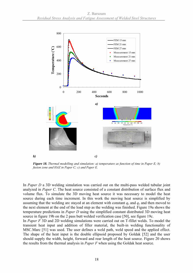
The parameter c [J/g°C] is the mass-specific heat capacity and the parameter ρ [g/mm3] is the density. The parameter Qv [J/mm3] is the rate of temperature change due to heat generated per volume, and λ/cρ is the material-and temperature-dependent coefficient of thermal diffusivity κ [mm2/s]. The temperature field in equation (3) could either be stationary (i.e. steady-state), the temperature field is then time-constant at all points, i.e. ∂T/∂t = 0, or non-stationary (i.e. transient), then the temperature field is determined on the material side by the thermal diffusivity. The characteristic of heat flow during arc welding is that the heat source moves at constant speed on the surface of the work piece, and that the size of the heat source is small compared to the size of the work piece. In Paper C a 2D axisymmetric welding analysis was carried out on a multi-pass welded tubular joint. The heat input model used was with constant distribution of surface and volume flux. The predictions showed reasonably good agreement with micro samples of the fusion zone and the heat affected zone (HAZ), see figure 18b. In Paper E development of a 2D FE subroutine was carried out for welding simulation procedure in order to predict the residual stresses due to the welding process. The heat input consisted of a constant volume flux and prescribed initial activation temperature of 1500 ˚C for the weld filler. Also guidelines and recommendations for modelling of a 2D simplified welding heat source are outlined in Paper E. Figure 18a shows the temperature predicted using the heat source in Paper E compared to measurements. Figure 18c shows the fusion zone and HAZ predictions compared with micro samples for a verification example found in the literature [50].
y z
x
Welding direction
Weld path
Z. Barsoum Residual Stress Analysis and Fatigue Assessment of Welded Steel Structures
18
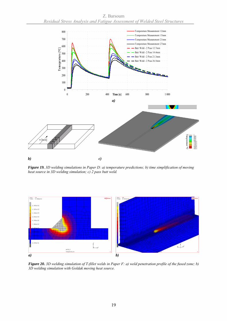
In Paper D a 3D welding simulation was carried out on the multi-pass welded tubular joint analyzed in Paper C. The heat source consisted of a constant distribution of surface flux and volume flux. To simulate the 3D moving heat source it was necessary to model the heat source during each time increment. In this work the moving heat source is simplified by assuming that the welding arc stayed at an element with constant qs and qv and then moved to the next element at the end of the load step as the welding was finished. Figure 19a shows the temperature predictions in Paper D using the simplified constant distributed 3D moving heat source in figure 19b on the 2 pass butt welded verification case [50], see figure 19c. In Paper F 3D and 2D welding simulations were carried out on T-fillet welds. To model the transient heat input and addition of filler material, the built-in welding functionality of MSC.Marc [51] was used. The user defines a weld path, weld speed and the applied effect. The shape of the heat input is the double ellipsoid proposed by Goldak [52] and the user should supply the width, height, forward and rear length of the heat source. Figure 20 shows the results from the thermal analysis in Paper F when using the Goldak heat source.
0
200
400
600
800
0 200 400 600 800 1000Seconds
Tem
pera
ture
(˚C
)
FEM 15 mmFEM 21 mmFEM 27 mmMeasurement 15 mmMeasurement 21 mmMeasurement 27 mm
a)
b)
c)
Figure 18. Thermal modelling and simulation: a) temperature as function of time in Paper E; b) fusion zone and HAZ in Paper C; c) and Paper E.
Z. Barsoum Residual Stress Analysis and Fatigue Assessment of Welded Steel Structures
19
0
100
200
300
400
500
600
700
800
0 200 400 600 800 1 000Time [s]
Tem
epra
ture
[°C
]
Temperature Measurement 12mm
Temperature Measurement 15mmTemperature Measurement 21mmTemperature Measurement 27mmButt Weld - 2 Pass 12.7mmButt Weld - 2 Pass 14.4mm
Butt Weld - 2 Pass 21.3mmButt Weld - 2 Pass 26.5mm
a)
b) c) Figure 19. 3D welding simulations in Paper D: a) temperature predictions; b) time simplification of moving heat source in 3D welding simulation; c) 2 pass butt weld.
a) b) Figure 20. 3D welding simulation of T-fillet welds in Paper F: a) weld penetration profile of the fused zone; b) 3D welding simulation with Goldak moving heat source.
Z. Barsoum Residual Stress Analysis and Fatigue Assessment of Welded Steel Structures
20
Welding residual stresses The residual stresses caused by inhomogeneous temperatures are termed thermal stresses. These elastic thermal stresses disappear after removing the inhomogeneous temperatures which cause them. Where major differences in temperature exist, the thermal stresses give rise to plastic deformation and, after removal of the temperature differences and complete cooling, residual stresses remain. During the welding process the weld area is heated up significantly relative to the surrounding area and fused locally. The material expands as a result of being heated. The heat expansion is restrained by the surrounding colder area, which gives rise to elastic thermal stresses. The thermal stresses partly exceed the yield limit, which is lowered at elevated temperatures. Consequently the weld area is plastically hot-compressed and, after cooling down, it thus displays tensile residual stresses, and the surrounding area compressive residual stresses. The fundamental equations in the thermo-elastic-plastic analysis of welds are:
1. A change in temperature, ΔT, causes a volumetric strain αΔT. 2. At each point, the strain increment can be defined as
Thermalij
Plasticij
Elasticij
Totij dddd εεεε ++= (7)
klijkl
Elasticij dDd σε 1−= (8)
ij
Plasticij
Fdσ
λε∂∂
= (9)
ij
Thermalij Td δαε Δ= (10)
3. The material obeys isotropic/kinematic hardening hypothesis. 4. The material properties e.g. the Young’s modulus and the yield strength are assumed
to be temperature dependent. Finite element modelling of welding residual stresses Several authors have summarized information on the application of the finite element method to the simulation of residual stresses during and after welding, e.g. Lindgren [46-48]. Lindgren [46-47] discussed the approach for accounting for thermo mechanical couplings and corresponding computational strategies and the difficulties of the material modelling during the welding process. In Lindgren [48], the increasing accuracy of welding simulations depending on the modelling process and the opportunity to use larger models is outlined. Radaj [53] discussed the intelligent solution and simplification using the finite element method to simulate the complex welding process. Small strain approximations are often used, although welding often leads to visible deformation. Most analyses are performed in two steps. The thermal analysis is followed by the mechanical analysis. In the case of completely decoupled calculation of the temperature
Z. Barsoum Residual Stress Analysis and Fatigue Assessment of Welded Steel Structures
21
field and the residual stresses, the transient temperature field is first stored for all time steps and is then used as an input data file for the residual stress calculations. Identical meshes and time steps are mandatory when this method is used. The thermal and mechanical analysis can be performed in a so-called staggered approach or simultaneously. The thermal dilatation, which is the sum of the thermal expansion and the volume changes, is the driving force and therefore each time step is usually started by solving for the temperatures, Tn+1, for time tn+1 and thereby using the geometry xn. The geometry is updated in the subsequent mechanical analysis for this time step. Thus the updating of the geometry in the thermal analysis lags one time step behind the mechanical analysis. Some analysis only takes the thermal expansion into account, and there exist different approaches for including the effect of the microstructure, that is the dependence of the material properties on the history of the thermo mechanical process. A coarse element mesh may be adequate. In the case of a more detailed analysis the chosen mesh fineness may not have much influence on the accuracy of the calculation result. The residual stress calculation requires a mesh refinement which is extended some distance from the moving heat source. Such an adaptive mesh design oriented towards the result error may considerably increase the efficiency of calculation. This advantage is even more important when solving three dimensional problems. In multi-pass welding different techniques exist in order to simplify the simulation. Analyzing multi-pass welds as a series of single-pass welds is rigorous. Lumping successive passes together is one way to reduce the computing time. Other simplification of the thermal and mechanical process is to either merge some weld passes into larger welds or accounting for some of the weld passes. To be able to add the filler material, especially in multi-pass welding the technique of element “birth and death” is suitable as described in the FE-software ANSYS [22]. All the elements are defined in the model and born in the later stage of the analysis. Another approach by Lindgren [46] is called quiet element where the whole structure is included in the computational model. The elements, corresponding to non laid welds, should be given material properties so that they do not affect the rest of the model. The elements are given normal material properties at the start of the weld pass, and all the strains and stresses that have been accumulated are removed. In Papers C, D E and F extensive welding simulations were carried out on fillet welds, butt welds and pipe welds focusing on accurate prediction of the residual stress after welding. Material modelling The thermal material characteristic values, expressed in equation (6) are in reality temperature-dependent and not constant, the extent of the change varying according to the kind of material. When the values of thermal properties are treated as variables that change with the temperature, equation (6) becomes non-linear and the mathematical analysis becomes extremely complex. However, the greatest limitation in welding simulation is the problem of obtaining accurate temperature-dependent material properties, especially at the higher temperature regime, T > 700 ˚C. These are at best reasonable approximations at present. The phase change during heating and cooling of typical low-alloy steels also has an influence on accurate modelling of the temperature field and the residual stress formation. It is evident that the material model needs to represent the real material behaviour with sufficient accuracy.
Z. Barsoum Residual Stress Analysis and Fatigue Assessment of Welded Steel Structures
22
Material properties are divided in two groups; the temperature-dependent thermo-physical properties (thermal conductivity, specific heat and density) used for the thermal analysis and the temperature-dependent mechanical properties (thermal expansion, Young’s modulus, Poisson’s ratio and yield stress) used for the coupled thermo-mechanical analysis. The metal adjacent to a weld is exposed to rapid thermal cycles and often undergoes changes in microstructure when it is subjected to elevated temperatures. These phase changes in turn influence the thermal properties, making them time- as well as temperature-dependent. The microstructure and hardness of the heat-affected zone depend upon the cooling rate, and this rate is influenced by various factors including plate thickness, welding conditions, preheat, the length of the weld, joint geometry, etc. For typical carbon steels the yield stress is considerably reduced for temperatures above 800 ˚C and naturally vanishes at the melting temperature. The high temperature range, T ≥ 0.5*Tmelting, is of little significance for the formation of residual stresses because of the disappearing yield limit in this range [49]. Therefore a cut-off temperature of Tcut-off = 0.5*Tmelting is used in the mechanical material model, i.e. if the temperature from the thermal analysis is higher than Tcut-off then material properties are evaluated at the Tcut-off temperature. The microstructure changes during heating (from ferrite and pearlite to austenite) and cooling (from austenite to ferrite, pearlite, bainite and/or martensite) depend on temperature and cooling rates. The evolution of microstructure can take the form e.g. of grain growth and precipitation and is introduced by e.g. annealing processes and will have an influence on the material properties. The microstructure evolution during welding can be an important factor for the final formation of the residual stresses. For example the austenite-martensite transformation will create compressive residual stresses since the volume change to martensite is greater. The closer the transformation temperature to room temperature, the more significant it is. Nowadays it is possible to include the microstructural evolution in the FE welding analysis in several FE codes, i.e. ANSYS [22] or ABAQUS [54]. Unfortunately, dealing with the lack of high temperature material data relevant to microstructural dependency and the resulting material properties in the heat affected zone is one of the most challenging tasks in computational weld mechanics. However, this is out of the scope of this thesis. RESIDUAL STRESS MEASUREMENT TECHNIQUES Many techniques have been used for measuring residual stresses in metals. These can be categorized in terms of the degree of damage to the metal they introduce: destructive, semi-destructive or non-destructive methods. In the destructive and semi-destructive methods the residual stresses are measured, by mean of stress-relaxation, by measuring the elastic-strain release that takes place when a sample is sectioned, drilled or milled using electrical or mechanical strain gauges. Resistance strain gauges, detachable extensometers and photo elastic surface layers are mainly used for measurements in practice. Although they are destructive or semi-destructive, the stress relaxation techniques provide reliable data and are the most widely used and frequently referred to [53, 55-57]. Hoe-drilling is semi-destructive in that the hole can be ground out or peened to prevent it acting as a source for fatigue crack initiation. In crystalline structures, elastic strain can be determined non-destructively by measuring the lattice parameter with X-ray diffraction. The most severe limitation is that it can be applied non-destructively only on the surface, the surface strain can be determined
Z. Barsoum Residual Stress Analysis and Fatigue Assessment of Welded Steel Structures
23
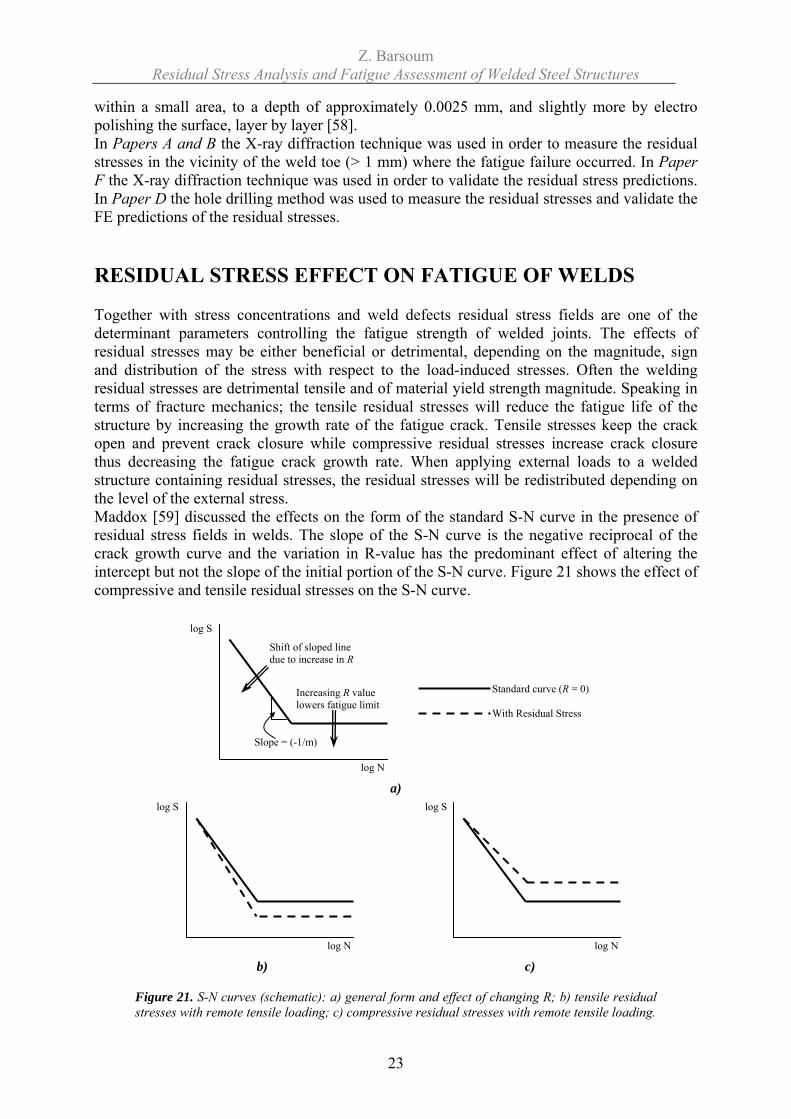
within a small area, to a depth of approximately 0.0025 mm, and slightly more by electro polishing the surface, layer by layer [58]. In Papers A and B the X-ray diffraction technique was used in order to measure the residual stresses in the vicinity of the weld toe (> 1 mm) where the fatigue failure occurred. In Paper F the X-ray diffraction technique was used in order to validate the residual stress predictions. In Paper D the hole drilling method was used to measure the residual stresses and validate the FE predictions of the residual stresses. RESIDUAL STRESS EFFECT ON FATIGUE OF WELDS Together with stress concentrations and weld defects residual stress fields are one of the determinant parameters controlling the fatigue strength of welded joints. The effects of residual stresses may be either beneficial or detrimental, depending on the magnitude, sign and distribution of the stress with respect to the load-induced stresses. Often the welding residual stresses are detrimental tensile and of material yield strength magnitude. Speaking in terms of fracture mechanics; the tensile residual stresses will reduce the fatigue life of the structure by increasing the growth rate of the fatigue crack. Tensile stresses keep the crack open and prevent crack closure while compressive residual stresses increase crack closure thus decreasing the fatigue crack growth rate. When applying external loads to a welded structure containing residual stresses, the residual stresses will be redistributed depending on the level of the external stress. Maddox [59] discussed the effects on the form of the standard S-N curve in the presence of residual stress fields in welds. The slope of the S-N curve is the negative reciprocal of the crack growth curve and the variation in R-value has the predominant effect of altering the intercept but not the slope of the initial portion of the S-N curve. Figure 21 shows the effect of compressive and tensile residual stresses on the S-N curve.
a)
b) c)
Figure 21. S-N curves (schematic): a) general form and effect of changing R; b) tensile residual stresses with remote tensile loading; c) compressive residual stresses with remote tensile loading.
log N
log S
Shift of sloped line due to increase in R
Increasing R value lowers fatigue limit
Slope = (-1/m)
Standard curve (R = 0)
With Residual Stress
log N
log S log S
log N
Z. Barsoum Residual Stress Analysis and Fatigue Assessment of Welded Steel Structures
24
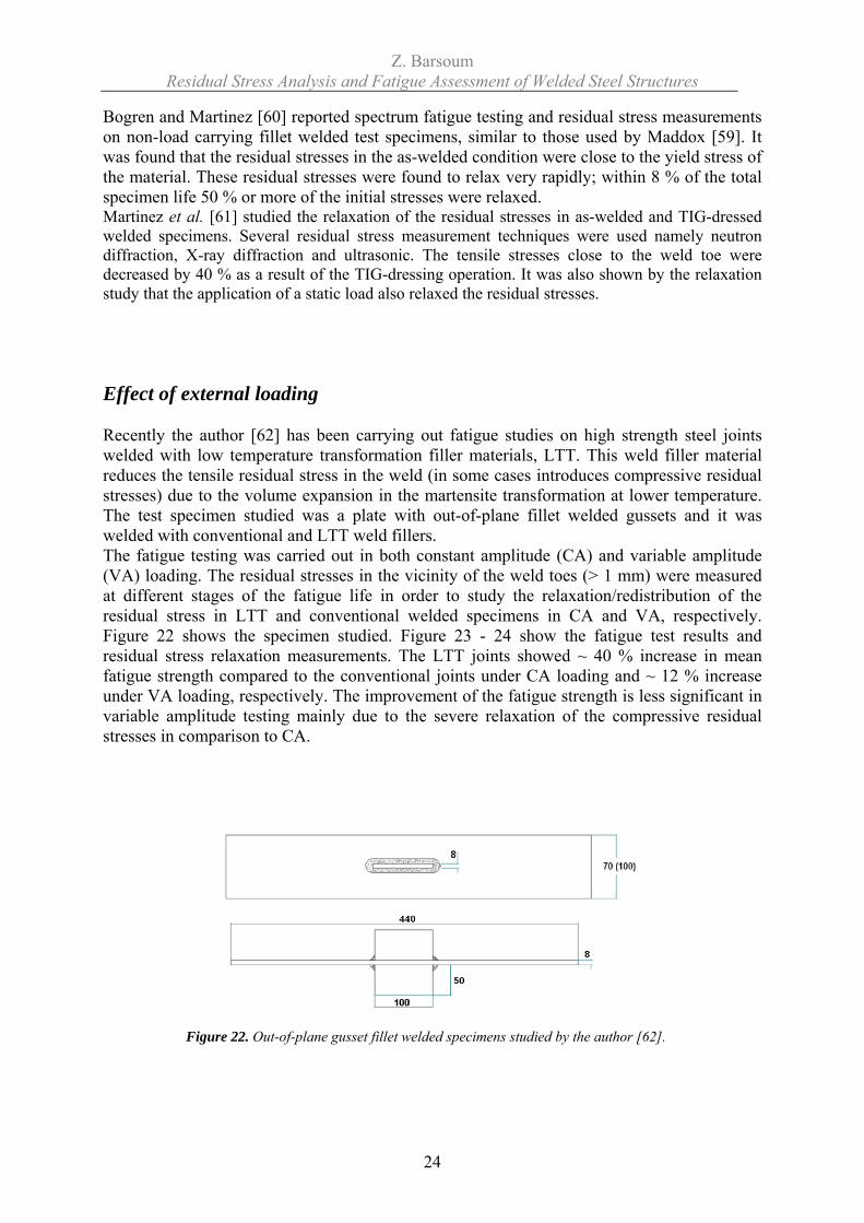
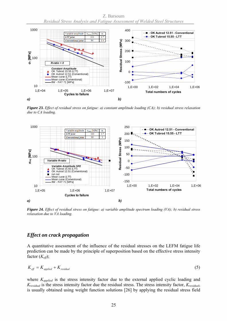
Bogren and Martinez [60] reported spectrum fatigue testing and residual stress measurements on non-load carrying fillet welded test specimens, similar to those used by Maddox [59]. It was found that the residual stresses in the as-welded condition were close to the yield stress of the material. These residual stresses were found to relax very rapidly; within 8 % of the total specimen life 50 % or more of the initial stresses were relaxed. Martinez et al. [61] studied the relaxation of the residual stresses in as-welded and TIG-dressed welded specimens. Several residual stress measurement techniques were used namely neutron diffraction, X-ray diffraction and ultrasonic. The tensile stresses close to the weld toe were decreased by 40 % as a result of the TIG-dressing operation. It was also shown by the relaxation study that the application of a static load also relaxed the residual stresses. Effect of external loading Recently the author [62] has been carrying out fatigue studies on high strength steel joints welded with low temperature transformation filler materials, LTT. This weld filler material reduces the tensile residual stress in the weld (in some cases introduces compressive residual stresses) due to the volume expansion in the martensite transformation at lower temperature. The test specimen studied was a plate with out-of-plane fillet welded gussets and it was welded with conventional and LTT weld fillers. The fatigue testing was carried out in both constant amplitude (CA) and variable amplitude (VA) loading. The residual stresses in the vicinity of the weld toes (> 1 mm) were measured at different stages of the fatigue life in order to study the relaxation/redistribution of the residual stress in LTT and conventional welded specimens in CA and VA, respectively. Figure 22 shows the specimen studied. Figure 23 - 24 show the fatigue test results and residual stress relaxation measurements. The LTT joints showed ~ 40 % increase in mean fatigue strength compared to the conventional joints under CA loading and ~ 12 % increase under VA loading, respectively. The improvement of the fatigue strength is less significant in variable amplitude testing mainly due to the severe relaxation of the compressive residual stresses in comparison to CA.
Figure 22. Out-of-plane gusset fillet welded specimens studied by the author [62].
Z. Barsoum Residual Stress Analysis and Fatigue Assessment of Welded Steel Structures
25
10
100
1000
1,E+04 1,E+05 1,E+06 1,E+07Cycles to failure
σ r [M
Pa]
Constant AmplitudeOK Tubrod 15.55 (LTT)OK Autrod 12.51 (Conventional)Mean curve (LTT)Mean curve (Conventional)IIW - FAT 71 [MPa]
R-ratio = 0
-100
0
100
200
300
400
1,E+00 1,E+02 1,E+04 1,E+06Total numbers of cycles
Res
idua
l Str
ess
(MPa
)
OK Autrod 12.51 - ConventionalOK Tubrod 15.55 - LTT
a) b) Figure 23. Effect of residual stress on fatigue: a) constant amplitude loading (CA); b) residual stress relaxation due to CA loading.
10
100
1000
1,E+05 1,E+06 1,E+07Cycles to failure
σ eq [M
Pa]
Variable Amplitude SP2OK Tubrod 15.55 (LTT)OK Autrod 12.51 (Conventional)run outMean curve (LTT)Mean curve (Conventional)IIW - FAT 71 [MPa]
Variable R-ratio
-150
-100
-50
0
50
100
150
200
250
1,E+00 1,E+02 1,E+04 1,E+06Total numbers of cycles
Res
idua
l Str
ess
(MPa
)
OK Autrod 12.51 - ConventionalOK Tubrod 15.55 - LTT
a) b) Figure 24. Effect of residual stress on fatigue: a) variable amplitude spectrum loading (VA); b) residual stress relaxation due to VA loading. Effect on crack propagation A quantitative assessment of the influence of the residual stresses on the LEFM fatigue life prediction can be made by the principle of superposition based on the effective stress intensity factor (Keff);
residualappliedeff KKK += (5) where Kapplied is the stress intensity factor due to the external applied cyclic loading and Kresidual is the stress intensity factor due the residual stress. The stress intensity factor, Kresidual, is usually obtained using weight function solutions [26] by applying the residual stress field
Z. Barsoum Residual Stress Analysis and Fatigue Assessment of Welded Steel Structures
26
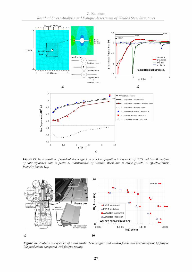
on the un-cracked component. However, these weight function techniques only gives qualitative results, are outdate and are valid only for elementary cases. In order to achieve a more accurate determination of Kresidual the residual stress distribution has to be known at each stage of the crack growth [64]. Linear elastic fracture mechanics (LEFM) is frequently employed for fatigue assessment of cracks and flaws in critical welds. The approaches available for the incorporation of residual stresses into the LEFM fatigue life assessment are the mean stress method and the crack closure method. The mean stress method changes the crack growth rate by an alteration of the mean stress at the crack tip by an effective stress ratio Reff. The crack closure approach assumes an open crack if Keff > 0 and a closed crack if Keff < 0. In the SINTAP defect assessment procedure, [65], the superposition of stress-intensity factors as shown above is employed and stress redistribution is accounted for using a correction factor for Kres. Michaleris et al. [66] presented a finite element methodology for the incorporation of residual stress effects into fracture assessment. Following the welding simulation, interpolation is used to transfer the computed residual stresses onto fine meshes for evaluation of fracture mechanical parameters. Additionally, the effect of the welding residual stress field on uncertainties in fatigue life predictions was modelled by Josefson et al. [67]. Figure 25 shows an example of a cold expanded hole analyzed in Paper E where the effect of the residual stress on the FCG was analyzed by FEM and LEFM. The procedure was then applied to a welded steel structure. A welded ship engine frame box at MAN B&W was analyzed in Paper E regarding residual stresses and fatigue assessment from the weld root using LEFM. The welding simulation procedure, residual stress mapping algorithm and LEFM subroutine developed in Paper E were used for the analysis. Figure 26a shows the welded engine part analyzed while figure 26b shows the fatigue life predictions in comparison with fatigue testing.
Z. Barsoum Residual Stress Analysis and Fatigue Assessment of Welded Steel Structures
27
a)
-1,5
-1
-0,5
0
0,5
0 1 2 3r / R (-)
σre
sidu
al st
ress
/ σ
yiel
d st
ress
(-)
No crack a=0.3 mm a=3 mma= 8 mm
Radial Residual Stress-σy
0.3 mm3 mm
8 mm
b)
-0,7
-0,4
-0,1
0,2
0,5
0,8
1,1
1,4
0 0,5 1 1,5 2 2,5r / R (-)
Kef
f / σ
yiel
d st
ress( π
R)2 (
-)
Analytical solution
2D FE (LEFM) - External load
2D FE (LEFM) - External + Residual stress
2D FE (LEFM) - Residual stress
2D FE (non cold worked), Pavier et al
2D FE (cold worked), Pavier et al
3D FE (mid thickness), Pavier et al
c)
Figure 25. Incorporation of residual stress effect on crack propagation in Paper E: a) FCG and LEFM analysis of cold expanded hole in plate; b) redistribution of residual stress due to crack growth; c) effective stress intensity factor, Keff.
WELDED ENGINE FRAME BOX10
100
1,E+04 1,E+05 1,E+06 1,E+07Nf (Cycles)
Rig
forc
e (k
N)
PWHT experiment
PWHT prediction
As Welded experiment
As Welded Prediction
run outs
a) b) Figure 26. Analysis in Paper E: a) a two stroke diesel engine and welded frame box part analysed; b) fatigue life predictions compared with fatigue testing.
Z. Barsoum Residual Stress Analysis and Fatigue Assessment of Welded Steel Structures
28
DISCUSSION Fatigue failure is still the dominating cause for breakdown of many welded structures in construction and mining equipment, trains, ships, agricultural machinery, bridges and off shore equipment. The fatigue design of these structures is governed by relatively conservative fatigue design codes with no or small differentiation for different welding quality. The global challenge of saving resources will promote the development of more light-weight and effective structures for many types of machinery and installations. Fatigue design of welded joints has been developed during the last 35 years. For many years the only applicable method for the fatigue assessment of welded structures was the nominal stress method or structural testing of welded parts or components. The major type of welding process was manual arc welding. Nowadays more sophisticated fatigue assessment methods have been developed e.g. notch stress method and LEFM and the welding processes are faster and more productive e.g. robotized hybrid laser and arc welding methods. The trend moves towards optimized welded structures regarding cost and weight and this requires high speed welding method producing high quality welds and reliable analysis tools for fatigue life assessment. A draft of a weld quality rule based on local approach fatigue assessment methods, principally the effective notch stress and LEFM methods, was developed within the Nordic R&D project QFAB and is nowadays introduced as a weld class system corporate standard within Volvo and in the international community e.g. IIW (International Institute of Welding). Within the framework of this research work many aspects of fatigue design and manufacturing of welded joints has been studied and introduced into the industrial environment. It is clearly obvious that residual stress prediction and welding simulation in complex structures is elusive and employs many researchers for compilation of residual stress distribution for welded joints. Two of the important issues regarding welding simulation, besides the complexity and high degree of nonlinearity of the problem, are the quantification of net heat input supplied by the welding arc and the modelling of material behaviour at higher temperatures. Both are important in order to have an accurate model in successful welding simulations. As a general rule it can be stated that all production components and structures contain residual stresses that influence fatigue strength. Lack of penetration, lack of fusion or “design root cracks” in load-carrying fillet welded joints, cold laps and undercuts will all act as initial cracks from which fatigue cracks can propagate. If the applied stress intensity variation is high enough and the residual stress level is in tension, then the fatigue life will be shorter than if the residual stress is in compression. The computational effort needed to predict the residual stress field in complex welded structures and their relaxation during spectrum fatigue loading will be the major future challenge in the design of advanced fabricated structures. Another aspect of the design of welded structures against fatigue is the introduction of post weld improvement techniques which have evolved the international industrial and scientific community. Significant progress has been made with weld improvement methods as developed for fatigue design rules for improved welded joints within IIW Commission XIII (Fatigue design of welded structures) [68]. The weld improvement techniques such as shot peening, hammer peening [69] and Ultrasonic Impact Treatment (UIT) [70-71] focus on improving the weld toe region by enlarging the toe radius, reducing the weld defects and introducing compressive residual stresses. Improvement methods will also support the use of higher strength materials, an alternative which traditionally has been limited by older design rules. Following effective improvement of the weld toe failure tends to move to other locations such as interbead toes and the weld root. The assessment of the weld root will be more important in connection with weld improvement.
Z. Barsoum Residual Stress Analysis and Fatigue Assessment of Welded Steel Structures
29
Finally, the challenge for the international scientific and industrial community, in order to be able to design and manufacture lightweight, effective welded structures may be listed as
Apply local design methods, Assess residual stress fields including relaxation,
Apply weld improvement methods in highly stressed areas,
Specify and monitor the needed weld quality needed,
Improve weld inspection tools for general purpose.
CONCLUSIONS
The majority of weld defects found in high speed single run MAG welding are cold laps in connection with spatter. The existence of cold lap in connection with good weld geometry reduces the weld quality. In the case of small toe radius the problem with cold laps is overturned by high stress concentration factor.
It is indicated that spatter-induced cold laps could be expected to have 2-3 times
longer fatigue life than line cold laps. Special effort is needed to avoid or eliminate these kinds of flaws e.g. by an alternative welding process.
Good fatigue strength and relatively small scatter was observed in the local weld
geometry and the fatigue life for specimens welded with manual FCAW. In some specimens welded with FCAW almost no weld defects were found in form of cold laps.
The lack of weld root penetration has a major influence on the fatigue life of fillet-
welded joints. However, it has been shown that the weld root in e.g. the welded tubular joints is under favourable compressive residual stresses and this will enhance the fatigue life. The residual stress at the vicinity of the weld root is at present difficult to measure hence welding simulations are used to quantify these.
The developed welding simulation procedures with 2D models, simplified material
models and heat source tend to predict residual stresses with sufficient accuracy and with 30-100 times shorter computational time compared with 3D welding analysis. The developed welding simulation procedure is a valid tool for residual stress prediction for further accurate fatigue life predictions.
The fatigue life prediction for the diesel engine welded frame box using the developed
LEFM subroutine and the residual stress mapping procedure confirms the fatigue life enhancement observed in the fatigue testing of the as-welded specimens compared with the stress relived. This illustrates the significant effect of residual stress on the fatigue life and hence should be included in the fatigue life assessment using LEFM.
Z. Barsoum Residual Stress Analysis and Fatigue Assessment of Welded Steel Structures
30
SUGGESTION FOR FUTURE WORK
Tools for better fatigue life prediction and equivalent mixed mode crack growth models are required.
Better and more effective detection and characterisation methods of weld defects (cold
laps) in connection with fatigue testing.
General models for residual stress relaxation in variable amplitude spectrum loading. SUMMARY OF APPENDED PAPERS In Paper A fatigue testing and weld quality of Hybrid Nd: YAG laser/MAG and MAG welded (tandem arc solid wire, flux cored wire, tandem flux cored wire) non-load carrying cruciform joints is examined. Four batches were produced, tested and the results were compared. The local weld geometry of the cruciform welded joints was measured and analyzed. Residual stress measurement was carried out close to the toe region using the X-ray diffraction. Weld defects (cold laps) in the cracked specimens was measured. The MAG flux cored wire welded batch showed best fatigue resistance (FAT 136 MPa), low residual stresses (-40 to -180 MPa) and almost no weld defects (cold laps << 0.03 mm). In Paper B fatigue testing and defect assessment were carried out on specimens welded with robotic and manual welding using flux cored (FCAW) and metal cored (MCAW) filler materials in order to study the effect of the welding method on the fatigue strength, weld quality and weld defects. The few largest defects were removed by the shot peening process, although small defects survived. This led to a smaller scatter in fatigue live for the shot peened specimens. The fatigue life predictions using 2D LEFM FE-model for simulating a continuous cold lap defect along the weld toe showed a qualitative agreement with the fatigue test results. A 3D LEFM analysis of crack growth from a spatter -induced cold lap defect was also carried out. This showed similar trends in crack growth compared to the 2D analysis of a continuous cold lap, although the spatter-induced cold lap defect (semi-elliptical) had a longer fatigue life (x2.7), and hence is less dangerous from a fatigue point of view. In Paper C the residual stresses in multi-pass welded tube-to-plates were studied. Two different tubular joint configurations were studied; a three-pass single-U weld groove for maximum weld penetration and a two-pass fillet (no groove) welded tube-to-plates for minimum weld penetration. The three pass welded tubular joint showed nearly double the residual compressive stress level near the weld root (-230 MPa) as compared to the two-pass weld (-120 MPa). Torsion fatigue tests were performed in order to study crack propagation from the weld root, lower and upper weld toe in Mode III. Some tubes were stress relieved (PWHT) and some was fatigue tested with internal static pressure. LEFM was employed in order to assess the effect of the residual stress. In Paper D a three dimensional finite element welding simulation of the 3 pass welded tubular joint was carried out. The calculated temperatures in the transient thermal analysis were compared with temperature measurements. The FE predicted residual stresses in the as-
Z. Barsoum Residual Stress Analysis and Fatigue Assessment of Welded Steel Structures
31
welded conditions were verified with hole drilling strain gage measurements. The residual stresses was used as internal stresses in the finite element model for the torsion fatigue simulation in order to study the relaxation of the residual stresses in constant amplitude loading. In Paper E a welding simulation procedure is developed using the FE-software ANSYS in order to predict residual stresses. A subroutine for LEFM analysis was developed in 2D in order to predict the crack path of propagating fatigue cracks. A subroutine was developed in order to incorporate the predicted residual stresses and their relaxation during crack propagation by stress mapping between meshes without and with cracks, respectively. The objective was to investigate fatigue test results from special designed test bars from a welded ship engine frame box at MAN B&W where all test failed from the non-penetrated weld root. The LEFM fatigue life predictions shows good agreement with the fatigue test result when the residual stresses are taken into account in the crack growth analysis. In Paper F two- and three dimensional finite element welding simulations have been carried out on a T-fillet weld. The objective is to study the residual stresses and the 3D effect of the welding process. Moreover, welding simulations using solid models and contact models in the unfused weld roots were carried out in order to investigate the possible effect with respect to the residual stresses. Residual stress measurements were carried out using X-ray diffraction technique. The 2D residual stress predictions shows good agreement with measurements, and is suitable for residual stress predictions for incorporation in further fatigue crack growth analysis from weld defects emanating from the weld toe and root. REFERENCES
[1] Samuelsson J., Fatigue design of vehicle components methodology and applications, Dept. of Aeronautical Structures and Materials, Report No. 88-23, The Royal Institute of Technology, Stockholm 1988.
[2] Martinsson J., Fatigue assessment of complex welded steel structures, Doctoral
Thesis, Dept. of Aeronautical and Vehicle Engineering, KTH, Sweden 2005, ISBN 91-2783-968-6.
[3] Pettersson G., Fatigue assessment of welded structures with non-linear boundary
conditions, Licentiate Thesis, Dept. of Aeronautical and Vehicle Engineering, KTH, Sweden 2004, ISBN 91-7283-948-1.
[4] Byggnevi M., LEFM analysis and fatigue assessment of welded structures, Licentiate
Thesis, Dept. of Aeronautical and Vehicle Engineering, KTH, Sweden 2005, ISBN 91-7178-094-7.
[5] Radaj D. and Sonsino C. M., Fatigue assessment of welded joints by local
approaches, Abington Publishing, 1998.
Z. Barsoum Residual Stress Analysis and Fatigue Assessment of Welded Steel Structures
32
[6] Hansen J. L., Residual stress from welding of large diesel engine structures, Proc. Design and Analysis of Welded High Strength Steel Structures, Stockholm June 2002, 345-372, ed. Samuelsson J., EMAS Ltd. 2002.
[7] Finch D. and Burdekin F. M., Effect of welding residual stress on significance of
defects in various types of welded joints, Engineering Fracture Mechanics, Vol. 41, No.5, pp.721-735, 1992.
[8] Marquis G., Samuelsson J., Agerskov H. and Haagensen P. J., (editors) Integrated
Design and Manufacturing of Welded Structures, proceedings International symposium, March 13-14 Eskilstuna Report 18, Lappenranta University of Technology, 2007
[9] Hobbacher A., Fatigue design of welded joints and components, IIW doc. XIII-1539-
96, 1996. [10] Radaj D., Sonsino C. M., Fatigue assessment of welded joints by local approaches,
Abington Publishing, Cambridge, 1998. [11] Radaj D., Design and analysis of fatigue resistant welded structures, Abington
Publishing, Cambridge, 1990. [12] Olivier R., Köttgen V. B. and Seeger T., Schweißverbindung I (Welded Joints I),
FKM Forschungshefte 143, Frankfurt/M, FKM, 1989. [13] Olivier R., Köttgen V. B. and Seeger T., Schweißverbindung II,
Schwingfestigkeitsnachweise (Welded Joints II, Fatigue Assessments), FKM Forschungsheft 180, Frankfurt/M, FKM, 1994.
[14] Fricke W., Guideline for the fatigue assessment by notch stress analysis for welded
structures, IIW Doc. XIII-WG3-03r6-08, 6th draft, 2008. [15] Fricke W., Round-robin study on stress analysis for the effective notch stress
approach, IIW Doc. XIII-2129-06/XV-1223-06, 2006. [16] Jakobovskii V. V and Valteris I. I, Geometrical parameters of butt and fillet welds
and their influence on the welded joint fatigue life, IIW Doc XIII-1326-89, 1989. [17] Samuelsson J., Cold laps and weld quality acceptance limits, Design and Analysis of
Welded High Strength Steel Structures, pp. 151-163, Stockholm, EMAS, 2002. [18] Martinsson J., Fatigue strength of welded cruciform joints with cold laps, Design and
Analysis of Welded High Strength Steel Structures, pp. 163-185, Stockholm, EMAS, 2000.
[19] Lopez Martinez L. and Korsgren P., Characterisation of welded defect distribution
and weld geometry in welded fatigue test specimens, Fatigue under Spectrum Loading and Corrosive Environments, Warley, UK, EMAS, 1993.
Z. Barsoum Residual Stress Analysis and Fatigue Assessment of Welded Steel Structures
33
[20] Barsoum R. S., On the use of isoparametric finite elements in linear fracture mechanics, International Journal of Numerical Methods in Engineering, Vol.10, pp. 25-37, 1976.
[21] Henshell R. D. and Shaw K. G, Crack tip finite elements are unnecessary,
International Journal of Numerical Methods in Engineering, Vol. 9, pp. 495-507, 1975.
[22] ANSYS guide. ANSYS release 10.0. Swanson Analysis Systems: Houston. [23] Fehl B. and Truman K., An evaluation of fracture mechanics quarter-point
displacement techniques used for computing stress intensity factors, Engineering Strcutures, Vol. 21, pp. 406-415, 1999.
[24] FRANC2D. Version 3.2 http://www.cfg.cornell.edu/. [25] Bittencourt T. N., Wawrzynek P. A, Ingraffea A. R. and Sousa J. L., Quasi-
automatic simulation of crack propagation for 2D LEFM problems, Engineering Fracture Mechanics, Vol. 55, Issue 2, pp. 321-334, 1996.
[26] AFGROW. Version 4.0005. http://fibec.flight.wpafb.af.mil/fibec/afgrow.html. [27] BEASY. http://www.beasy.com/ [28] FRANC3D. http://www.cfg.cornell.edu/. [29] Björkblad A., A novel tool for crack modelling in finite element analyses, KTH, to be
published. [30] Hurd N. J. and Irving P. E., Factors influencing propagation of Mode III fatigue
cracks under torsional loading, ASTM STP 761, American Society for Testing and Materials, West Conshohocken, PA, pp. 212-233, 1982.
[31] Tschegg E. K., The influence of static I load Mode and R ratio on Mode III fatigue
growth behaviour in mild steel, Journal of Material Science & Engineering, Volume 59, pp. 127-137, 1983.
[32] Tschegg E. K., A contribution to Mode III fatigue crack propagation, Material
Science and Engineering, Vol. 54, pp. 127-36, 1982. [33] Socie D. and Marquis G., Multiaxial fatigue, Society of Automotive Engineering,
ISBN 0-7680-0453-5, USA, 2000. [34] Tjernberg A., Eriksson K., Torstensson H. and Holm D., Fatigue testing of electron,
laser and mag-welded transmission component, Welded High-Strength Steel Structures, EMAS, Stockholm, pp. 85-109, 1997.
Z. Barsoum Residual Stress Analysis and Fatigue Assessment of Welded Steel Structures
34
[35] Olsson K. E., Holm D. and Jakopvic F., High strength welded box beams subjected to torsion and bending fatigue loads – mode I and mode III stress intensity factors and crack growth predictions, Welded High-Strength Steel Structures, EMAS, Stockholm, pp. 179-197, 1997.
[36] Erdogan F. and Sih G. C., On the crack extension in plates under plane loading and
transverse shear, ASME Journal on Basic Engineering, Vol. 85, pp. 519-527, 1963. [37] Hussain M. A., Pu S. L., and Underwood J. H., Strain energy release rate for a crack
under combined mode I and II, ASTM STP 560, pp. 2-28, 1974. [38] Sih G. C., Strain energy density factor applied to mixed mode crack problems,
International Journal of Fracture Mechanics, Vol. 10, pp. 305-321, 1974. [39] Tanaka K., Fatigue propagation from a crack inclined to the cyclic tensile axis,
Engineering Fracture Mechanics, Vol. 6, pp. 493-507, 1974. [40] Sih G. C., Mechanics of fracture, Vol 1, Noordhoff International Publishing, Leyden,
pp.23-44, 1973. [41] Sih G. C. and Barthelemy B. M., Mixed mode fatigue crack growth predictions,
Engineering Fracture Mechanics, Vol. 13, pp. 439-451, 1980. [42] Richard H.A., In CD-Rom Proceedings of ICF10, Honolulu, USA, 2001. [43] Holst L., Lundin M., Hedegård J. and Weman K., High productive MAG-welding –
weld toe defects – a new detection method, Welded High-Strength Steel Structures, EMAS, Stockholm, pp. 73-84, 1997.
[44] Farajian-Sohi M. and Järvstråt N., Formation and detection of weld toe imperfections
in tandem gas metal arc welding, IIW doc. SG-212-1074-05, 2005. [45] Rosenthal D., The theory of moving sources of heat and its application to metal
treatment, Transaction of the A.S.M.E, pp. 849-65, 1946. [46] Lindgren L. E., Finite element modeling and simulation of welding, Part1: Increasing
complexity. Journal of Thermal Stresses, Volume 24, pp. 141-192, 2001. [47] Lindgren L. E., Finite element modeling and simulation of welding, Part2: Improved
material modeling.. Journal of Thermal Stresses, Volume 24, pp. 195-231, 2001. [48] Lindgren L. E., Finite element modeling and simulation of welding, Part3: Efficiency
and integration. Journal of Thermal Stresses, Volume 24, pp. 305-334, 2001. [49] Radaj D., Heat effects of welding, Berlin: Springer Verlag, pp. 19-128, 1992. [50] Hansen J. L, Numerical modelling of welding induced stresses, Dep. of
Manufacturing Engineering and Management, Technical University of Denmark, PhD Thesis, ISBN 87-90855-52-3, 2003.
Z. Barsoum Residual Stress Analysis and Fatigue Assessment of Welded Steel Structures
35
[51] MARC Analysis Research Corporation, Theory and user information, Palo Alto, 2007.
[52] Goldak J., Aditya B. and Malcom B., A new finite element model for welding heat
sources, Metallurgical Trans B, Vol. 15B, pp. 299-305, 1984. [53] Radaj D., Welding residual stresses and distortion: Calculation and measurement,
Düsseldorf: DVS Verlag , 2002. [54] Hibbit, Karlsson and Sorenson Inc., ABAQUS Theory Manual, 1998. [55] Masubuchi K., Analysis of welded structures, International Series on Material
Science and Technology, Volume 33, Massachusetts Institute of Technology, 1980. [56] Ruud C.O., Non-destructive and semi destructive methods for residual stress
measurement, Residual Stress Effects in Fatigue, ASTM STP 776, American Society for Testing and Materials, pp. 3-5, 1982.
[57] Mordfin L., Standard for residual stress measurement, Residual Stress Effects in
Fatigue, ASTM STP 776, American Society for Testing and Materials, pp. 6-12, 1982.
[58] Noyan I. C. and Cohen J. B., Residual stress measurements by diffraction and
interpretation, Verlag, New York, 1987. [59] Maddox S. J, Fracture mechanics applied to fatigue in welded structures, Welding
Institute Conference on Fatigue of Welded Structures, Brighton, England, pp. 73-96, 1970.
[60] Borgren J. and Lopez Martinez L, Spectrum fatigue testing and residual stress
measurements on non-load carrying fillet welded test specimens, Fatigue under Spectrum Loading and Corrosive Environments, Warley, UK, EMAS, 1993.
[61] Martinez Lopes L., Lin R., Wang D. and Blom A. F, Investigation of residual
stresses in as-welded and TIG-dressed specimens subjected to static/spectrum loading, Fatigue Behaviour of Welded High-Strength Steels, Department of Aeronautics, Report No. 97-30, The Royal Institute of Technology, Stockholm 1997.
[62] Barsoum Z. and Gustafsson M., Spectrum fatigue of high strength steel joints welded
with low temperature transformation consumables, Presented at 2nd International Conference on Fatigue Design, Senlis, France, 2007.
[63] Borgren J. and Lopez Martinez L., Spectrum fatigue testing and residual stress
measurements on non-load carrying fillet welded test specimens, Fatigue under Spectrum Loading and Corrosive Environments, Warley, UK, EMAS, 1993.
[64] Edwards L., Influence of residual stress redistribution on fatigue crack growth and
damage tolerant design, Material Science Forum Vols. 524-525, pp. 363-372, 2006.
Z. Barsoum Residual Stress Analysis and Fatigue Assessment of Welded Steel Structures
36
[65] Stacey A., Barthelemy J-Y., Leggatt R. H. and Ainsworth R. A., Incorporation of residual stresses into the SINTAP defect assessment procedure, Engineering Fracture Mechanics, Volume 67, pp. 573-611, 2000.
[66] Michaleris P., Kirk M., Mohr W. and McGaughy T., Incorporation of residual stress
effects into fracture assessment via the finite element method, Fatigue and Fracture Mechanics: Vol. 28, ASTM STP 1321, J.H. Underwood and B. D Macdonald, M. R. Mitchell, Eds., American Society for Testing and Materials, 1997.
[67] Josefson B. L., De Maré J., Svensson T. and Björklund S., In Engineering Against
Fatigue, edited by J.H. Beynon, M.W. Brown, R.A. Smith, T.C. Lindley and B. Tomkins, A.A. Balkema, Rotterdam, The Netherlands, pp. 365−371, 1999.
[68] Haagensen P., Recommendations on post weld improvement of steel and aluminium
structures, IIW, Doc. XIII-1815-00, 2000. [69] Nitschke-Pagel T. and Wohlfahrt H., Application of the local fatigue strength
concept for the evaluation of fatigue strength improvement techniques for welded joints, IIW, Doc. XIII-2099-06, 2006.
[70] Statnikov E.-S., Korostel V. and Marquis G., Development of ultrasonic impact
treatment technique, IIW, Doc. XIII-2098-06. [71] Statnikov E.-S. and Korostel V., On the assessment of ultrasonic impact treatment
effect on fatigue, IIW, Doc. XIII-2097-06.