Embed Size (px)
Citation preview
B. Iyer, S. Nalbalwar and R. Pawade (Eds.)
ICCASP/ICMMD-2016. Advances in Intelligent Systems Research.
Vol. 137, Pp. 100-106.
© 2017. The authors - Published by Atlantis Press This is an open access article under the CC BY-NC license (http://creativecommons.org/licens)es/by-nc/4.0/).
Residual Stress Analysis in Orthogonal Cutting of AISI 1020 Steel
O. Bhatkar1, S. Sakharkar
2*, V. Mohan
3, R. Pawade
4
1PGStudent, Finolex Academy of Management & Technology, Ratnagiri, India
2PG Student, Dr. Babasaheb Ambedkar Technological University, Lonere, India
3Associat Professor, Finolex Academy of Management & Technology, Ratnagiri, India
4Associate Professor, Dr. Babasaheb Ambedkar Technological University, Lonere, India
{[email protected], [email protected]}
Abstract:The aim of research work is to analyze residual stresses generated during shaper machining. This
paper presents the simulation of single point cutting process by finite element method and compared with
experimental work results. Taguchi L9 experimental design is used to obtain effective process parameters of
rake angle, depth of cut and cutting speed. High speed cutting tool steel is used for orthogonal cutting of AISI
1020 steel on shaper machine. The residual stresses are measured by X-ray sine2 ѱ diffraction method and finite
element software used to simulate residual stress analysis. In Taguchi designed experimentation rake angle 120,
depth of cut 1mm, and cutting speed 220m/min has been found optimum cutting parameter for optimize
compressive residual stresses.
Keywords: Residual stresses, orthogonal cutting, X-ray diffraction, FEM
1 Introduction
Metal cutting is the one of the most widely used operation in manufacturing industry and it has lots of research
investigation in both academic and industrial sectors. Cutting forces, temperatures, surface finish and stress
distributions are the more important final prediction factors for designing tool geometry and optimizing cutting
conditions. The surface quality of product has a main role in developing product characteristics. Surface quality
of product is mainly categorized into the machined product surface roughness, microstructure and residual
stresses. The residual stresses are an evident in surface roughness and play a decisive role for final product
manufacturing.
Residual stresses or locked in stresses are those stresses which existing within a body in the absence of external
loading or thermal gradient. These residual stresses are existing in structural material or component which at rest
or without application of any service or external load. The value of residual stress is higher near to surface of
component and decreases as increase in depth. These residual stresses are may be tensile or compressive and
layered differently with change in machining parameters such as depth of cut, cutting tool geometry, contact
conditions, chip- workpiece/ tool- workpiece contact. The compressive residual stresses are more important for
product performance and its life which promoted service and prevent crack nucleation but tensile residual
stresses led to premature failure, distortion and corrosion [1].
A few of research studies are available in machining on shaper tools. Shaper mainly used to make keyways in
the boss of pulley or gear, dovetail slides, internal spines and gear teeth with form tool [2]. During shaper
machining operation a large amount of force is exerted on machined surface in short time. AISI 1020 steel
material has huge demand in industrial application. This steel properties are well responds to cold working and
heat treatment operations therefore it used in shafts, lightly stressed gears, hard wearing surfaces, pins, chains
bulkheads of ships.Saoubhi et al. [3] investigated residual stress analysis in orthogonal machining of AISI 316L
steels. They found that temperature in machining zone associated with cutting forces which enabled the physical
mechanism for generation of residual stresses. The depth of residual stresses was determined by X- ray
diffraction method. The effects of cutting condition and too nature analysed for residual stresses with thermal
and mechanical event testing. Henriksen [4] concluded that physically attributed residual stresses in cutting
mainly because of mechanical effects which generated due to force exerted on cutting tool to the workpiece
during machining process and thermal stresses due to change in heat generation.
Residual Stress Analysis in Orthogonal Cutting of AISI 1020 Steel101
Okushimba and Kakino [5] states that the tensile residual stresses developed by heat generation/ temperature
effects and compressive residual stresses by mechanical actions regarding machining operation which similar to
Henriksen’s conclusions.
Matsumoto et al. [6] investigated the residual stresses in machining of AISI 4340 steel and revealed that
asincreasing depth of cut and feed during machining operation, machined surface was distorted and it causes to
increase in residual stresses.Navas et al. [7] revealed the effect of variable cutting tool geometry on surface
stresses. These residual stresses measured by X- ray diffraction method for different cutting speed, feed rate and
tool nose radius. They found that residual stresses increases due to raise in cutting temperature and with increase
in value of feed rate. The residual tensile stresses found less at cutting speed of 200m/min and 300m/min. Neseli
et al. [8] discussed in paper that surface finish affected by cutting tool geometry in metal turning operation.
They concluded that tool nose radius, rake angle and approach angle were significant factors for surface finish
and residual stress generation. Dogra et al. [9] investigated the effect of cutting tool geometry (tool nose radius,
rake angle, groove on rake face, edge geometry) in understanding mechanics of turning and stated that an
increase in chamfer angle will improved in tool life up to certain value and after that it will decreases. The size
of tool edge, nose radius effect on cutting mechanism, nose radius effect of surface roughness, residual stresses
of machined integrity.Bery [10] analysed superficial residual stresses in machining of AA 6061-T6511 bar
stock. They used a 63.5 mm diameter face mill at various cutting speeds and observed a consistent pattern of
residual stresses which vary between tensile and compressive forces as the cutter rotates. They adapt low cost
mapping method to analyses superficial residual strain and stresses in machined components. Axir [11]
developed comprehensive experimental model for predicting residual stresses profiles. The main advantage of
this model over existing model was that it provided the effect of machining parameter on maximum residual
stress and determined both location and depth of maximum residual stress. The experimental model described
capability of predicting residual stresses in five different materials in turning operation. Liu and Guo [12]
investigated effects of sequential cut and tool chip friction on residual stresses in machining layer from the first
cut changes with chip thickness, cutting forces, residual stress and temperature of machined layer. Cebron et al.
[13] predicted the material hardening and residual stress in machining operation. The highly hardened steel
increased residual stresses by increasing feed rate and depth of cut. At cutting speed exceeding 120m/min
visible surface cracks generated due to higher tensile stresses which attributed to combine effect of yielding and
higher temperature.The literature review major revealed stress analysis for lathe and mill machine tools but it
provides insufficient knowledge of orthogonal cutting on shaper tools. Therefore simulation model and
experiments are conducted on shaper machine using Taguchi L9 array. The surface quality is measured in term
of residual stresses. This comprehensive experimental model predict the surface and sub-surface residual stress
profile in machining of AISI 1020 steel on shaper machine. This paper is focused on the finding out optimum
machining parameters for orthogonal cutting process considering the effect of residual stress on fatigue life of
machined component.
2 Experimental Work
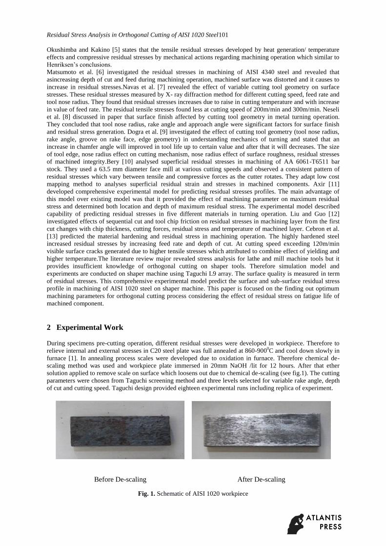
During specimens pre-cutting operation, different residual stresses were developed in workpiece. Therefore to
relieve internal and external stresses in C20 steel plate was full annealed at 860-9000C and cool down slowly in
furnace [1]. In annealing process scales were developed due to oxidation in furnace. Therefore chemical de-
scaling method was used and workpiece plate immersed in 20mm NaOH /lit for 12 hours. After that ether
solution applied to remove scale on surface which loosens out due to chemical de-scaling (see fig.1). The cutting
parameters were chosen from Taguchi screening method and three levels selected for variable rake angle, depth
of cut and cutting speed. Taguchi design provided eighteen experimental runs including replica of experiment.
Before De-scaling After De-scaling
Fig. 1. Schematic of AISI 1020 workpiece
102
Bhatkar et al.
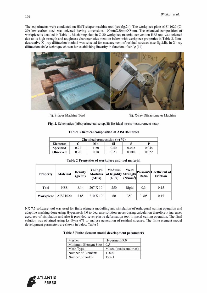
The experiments were conducted on HMT shaper machine tool (see fig.2.i). The workpiece plate AISI 1020 (C-
20) low carbon steel was selected having dimensions 100mmX50mmX8mm. The chemical composition of
workpiece is detailed in Table 1. Machining slots in C-20 workpiece material convention HSS tool was selected
due to its high strength and toughness characteristics mention below with workpiece properties in Table 2. Non-
destructive X –ray diffraction method was selected for measurement of residual stresses (see fig.2.ii). In X- ray
diffraction sin2ѱ technique chosen for establishing linearity in function of sin
2ѱ [14]
(i). Shaper Machine Tool (ii). X-ray Difractometer Machine
Fig. 2. Schematics (i)Experimental setup,(ii) Residual stress measurement setup
Table1 Chemical composition of AISI1020 steel
Chemical composition (wt %)
Elements C Mn Si S P
Specified 0.22 1.50 0.40 0.045 0.045
Observed 0.20 0.58 0.23 0.010 0.022
Table 2 Properties of workpiece and tool material
NX 7.5 software tool was used for finite element modelling and simulation of orthogonal cutting operation and
adaptive meshing done using Hypermesh 9.0 to decrease solution errors during calculation therefore it increases
accuracy of simulation and also it provided sever plastic deformation tool in metal cutting operation. The final
solution was obtained using Ls-Dyna 671 to analyse generation of residual stresses. The finite element model
development parameters are shown in below Table 3.
Table 3 Finite element model development parameters
Mesher Hypermesh 9.0
Minimum Element Size 0.5
Mesh Type Mixed (quads and trias)
Number of Elements 11800
Number of nodes 15321
Property Material Density
(g/cm3)
Young's
Modulus
(MPa)
Modulus
of Rigidity
(GPa)
Yield
Strength
(N/mm2)
Poisson's
Ratio
Coefficient of
Friction
Tool HSS 8.14 207 X 103 250 Rigid 0.3 0.15
Workpiece AISI 1020 7.85 210 X 103 80 350 0.305 0.15
Residual Stress Analysis in Orthogonal Cutting of AISI 1020 Steel103
In shaper operation, one degree of freedom and constrained to move along X-axis provided to shaper tool. Tool
was made rigid to avoid deformation of elements of tool. In group configuration, workpiece made as master and
tool as slave component. Machined model is time dependent due to stress- strain variation. Therefore this
problem was fall under non-linear category. Total solution of non linear category solved in carried solution in
step timer so 0.002 second increment selected to update stresses until full applied load was reached. The finite
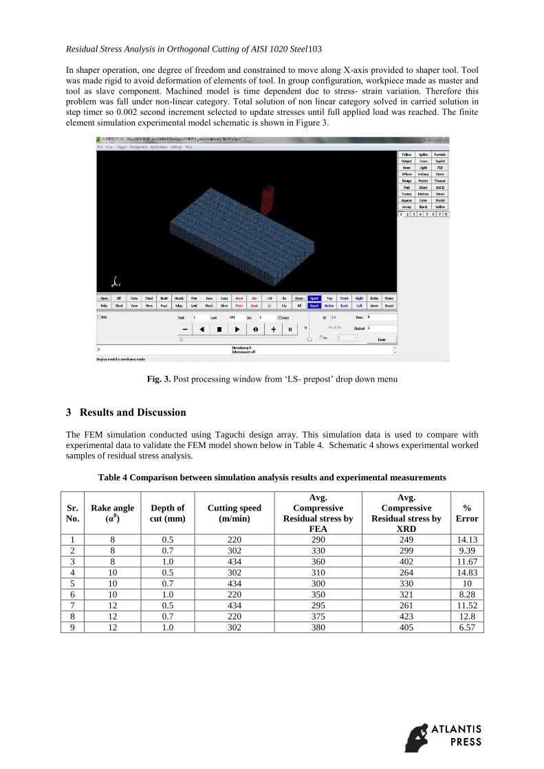
element simulation experimental model schematic is shown in Figure 3.
Fig. 3. Post processing window from ‘LS- prepost’ drop down menu
3 Results and Discussion
The FEM simulation conducted using Taguchi design array. This simulation data is used to compare with
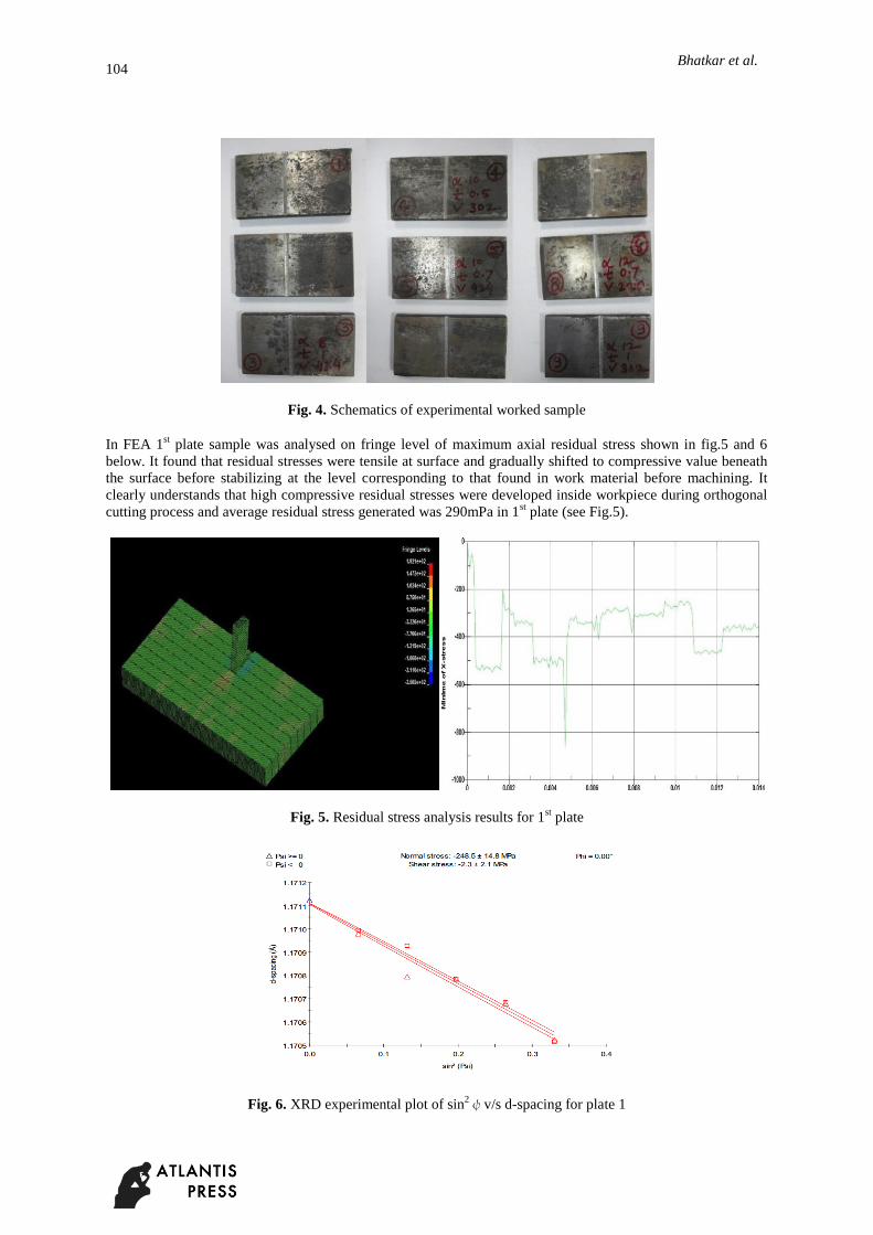
experimental data to validate the FEM model shown below in Table 4. Schematic 4 shows experimental worked
samples of residual stress analysis.
Table 4 Comparison between simulation analysis results and experimental measurements
Sr.
No.
Rake angle
(α0)
Depth of
cut (mm)
Cutting speed
(m/min)
Avg.
Compressive
Residual stress by
FEA
Avg.
Compressive
Residual stress by
XRD
%
Error
1 8 0.5 220 290 249 14.13
2 8 0.7 302 330 299 9.39
3 8 1.0 434 360 402 11.67
4 10 0.5 302 310 264 14.83
5 10 0.7 434 300 330 10
6 10 1.0 220 350 321 8.28
7 12 0.5 434 295 261 11.52
8 12 0.7 220 375 423 12.8
9 12 1.0 302 380 405 6.57
104
Bhatkar et al.
Fig. 4. Schematics of experimental worked sample
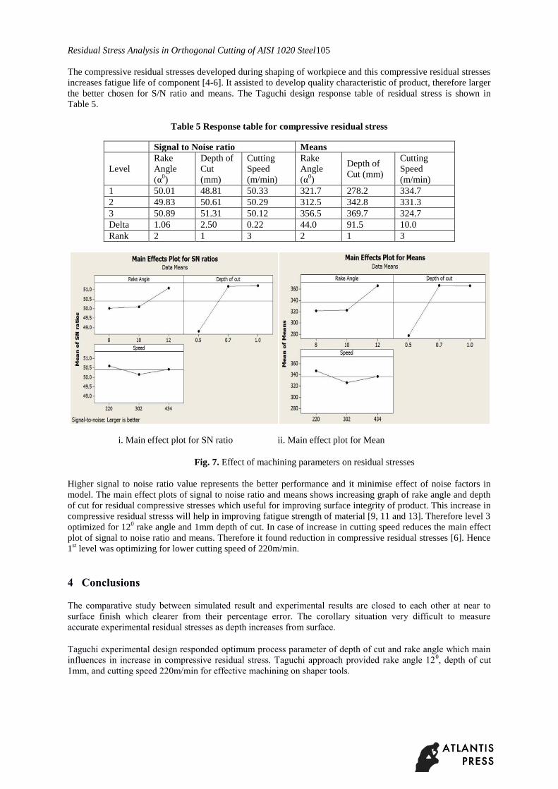
In FEA 1st plate sample was analysed on fringe level of maximum axial residual stress shown in fig.5 and 6
below. It found that residual stresses were tensile at surface and gradually shifted to compressive value beneath
the surface before stabilizing at the level corresponding to that found in work material before machining. It
clearly understands that high compressive residual stresses were developed inside workpiece during orthogonal
cutting process and average residual stress generated was 290mPa in 1st plate (see Fig.5).
Fig. 5. Residual stress analysis results for 1st plate
Fig. 6. XRD experimental plot of sin2ψv/s d-spacing for plate 1
Residual Stress Analysis in Orthogonal Cutting of AISI 1020 Steel105
The compressive residual stresses developed during shaping of workpiece and this compressive residual stresses
increases fatigue life of component [4-6]. It assisted to develop quality characteristic of product, therefore larger
the better chosen for S/N ratio and means. The Taguchi design response table of residual stress is shown in
Table 5.
Table 5 Response table for compressive residual stress
Signal to Noise ratio Means
Level
Rake
Angle
(α0)
Depth of
Cut
(mm)
Cutting
Speed
(m/min)
Rake
Angle
(α0)
Depth of
Cut (mm)
Cutting
Speed
(m/min)
1 50.01 48.81 50.33 321.7 278.2 334.7
2 49.83 50.61 50.29 312.5 342.8 331.3
3 50.89 51.31 50.12 356.5 369.7 324.7
Delta 1.06 2.50 0.22 44.0 91.5 10.0
Rank 2 1 3 2 1 3
i. Main effect plot for SN ratio ii. Main effect plot for Mean
Fig. 7. Effect of machining parameters on residual stresses
Higher signal to noise ratio value represents the better performance and it minimise effect of noise factors in
model. The main effect plots of signal to noise ratio and means shows increasing graph of rake angle and depth
of cut for residual compressive stresses which useful for improving surface integrity of product. This increase in
compressive residual stresss will help in improving fatigue strength of material [9, 11 and 13]. Therefore level 3
optimized for 120 rake angle and 1mm depth of cut. In case of increase in cutting speed reduces the main effect
plot of signal to noise ratio and means. Therefore it found reduction in compressive residual stresses [6]. Hence
1st level was optimizing for lower cutting speed of 220m/min.
4 Conclusions
The comparative study between simulated result and experimental results are closed to each other at near to
surface finish which clearer from their percentage error. The corollary situation very difficult to measure
accurate experimental residual stresses as depth increases from surface.
Taguchi experimental design responded optimum process parameter of depth of cut and rake angle which main
influences in increase in compressive residual stress. Taguchi approach provided rake angle 120, depth of cut
1mm, and cutting speed 220m/min for effective machining on shaper tools.
106
Bhatkar et al.
5 Future Scope
i. Dynamic- elastic tool material can be used instead of making rigid structure for tool analysis to find out
better optimum geometrical variables and cutting conditions.
ii. Flank and crater tool wear can be predicted by FEA modelling to understand significant undesirable
effects in cutting operations.
iii. Temperature effects can be considered to analyzed effect of cutting zone.
iv. Residual stress analysis can be carried out using oblique cutting processes instead of orthogonal cutting
operations.
References
[1]. Serope Kalpkjean,”Manufacturing Engineering Technology”, Third Edition, 1995.
[2]. https://en.wikipedia.org/wiki/Shaper
[3]. R.M. Saoubia, J.C. Outeirob, B. Changeuxa, J.L. Lebruna, A. Morao Dias, 'Residual stress analysis in
orthogonal Machining of standard and resulfurized AISI 316L steels', Journal of Materials Processing
Technology 96 (1999), pp- 225-233
[4]. E.K. Henriksen, “Residual stresses in machined surfaces”, Transactions ASME 73 (January 1951), pp-
265-278
[5]. K. Okushima, Y. Kakino, “A study on the residual stress produced by metal cutting”, Memoirs of the
Faculty of Engineering, Kuyoto 34 (1972), pp.234-248
[6]. Y. Matsumoto, M.M. Barash, C.R. Liu, “Effect of hardness on surface integrity of AISI 4340 steel”,
ASME Journal of Industrial Engineering 108 (1986), pp.169-175
[7]. Virginia Garcia Navas, Oscar Gonzalo, Ion Bengoetxea, “Effect of cutting parameters in the
surface residual stresses generated by turning in AISI 4340 steel” International Journal of Machine
Tools & Manufacture 61,pp.48–57, 2012
[8]. Suleyman Neseli, Suleyman Yaldız, Erol Turkes, “Optimization of tool geometry parameters for
turning operations based on the response surface methodology” Measurement 44,pp. 580–587, 2011
[9]. M. Dogra,V. S. Sharma, J. Dureja, “Effect of tool geometry variation on finish turning – A
Review” Journal of Engineering Science and Technology Review 4 (1), pp.1-13, 2011
[10]. J. E. Wyatt and J. T. Berry, “A New Technique for the Determination of Superficial Residual Stresses
Associated with Machining and Other Manufacturing Processes,” Journal of Materials Processing
Technology, Vol. 171, No. 1, 2006, pp. 132-140.
[11]. M.H. El-Axir, “A method of modeling residual stress distribution in turning for different materials',
International Journal of Machine Tools & Manufacture 42 (2002) pp.1055-1063
[12]. C.R. Liu, Y.B. Guo, 'Finite element analysis of sequential cuts and Tool chip friction on residual
stresses in a machined layer', International Journal of Mechanical Sciences 42 (2000), pp.1069-1086
[13]. M. Cebron, F. Kosel, J. Kopac, 'Effect of cutting on surface hardness and residual stresses for 12Mn
austenitic steel', Journal of Achievements in Materials and Manufacturing Engineering 55/1 (2012),
pp.80-89
[14]. Eyup Bagci,”3-D Numerical Analysis of Orthogonal cutting Process via Mesh free Method”,
International Journal of Physical Science, vol-6, (2011) 1267-1282.
[15]. I. Lazoglu, D. Ulutan, “An Enhanced Analytical Model for Residual Stress Prediction Machining”,
CIRP Annals, Manufacturing Technology (2008) 81-84


![VERSCHLUSSTECHNIK - Spezial-Baustoffe€¦ · Stainless steel A2 [ AISI 304 ] Acier inox A2 [ AISI 304 ] Aluminium Aluminium Aluminium 3,5 50 11 1/45 Stahl verzinkt Steel zinc plated](https://img.pdfslide.org/doc/110x75/604033782be25f25d31275d7/verschlusstechnik-spezial-baustoffe-stainless-steel-a2-aisi-304-acier-inox.jpg)