Embed Size (px)
Citation preview
1
Barunastra ITS
RoboBoat 2021: Technical Design Report
Barunastra ITS Roboboat Team Sitorus A, Alhakim A, Setiaji M, Rahman F, Ramadhan C, El-Hasan Z, Akbar A, Permatasari F, Hakim M, Tana V, Siraj F,
Medina Q, Indaryo A, Fadhlurrahman M, Ramadhan R, Aditya N, Solang D, Atmaja H, Kautaman G, Prawoto M,
Damayanti Z, Sundana P, Farhan A, Dikairono R.
Institut Teknologi Sepuluh Nopember
Surabaya, Indonesia
[email protected] Abstract—To compete in International Roboboat
Competition (IRC) 2021, Barunastra ITS proposed Nala
Poseidon, the new Autonomous Surface Vehicle (ASV)
design. This ASV is an improvement of the previous ASV
that have competed in IRC 2019. Small-Waterplane-
Area Twin-Hull is introduced to be the new ASV hull
type for its characteristics that decrease motion response
caused by waves. This hull ensures better vision sensor
reading due to decreased camera vertical movements
affected by disturbed flow downstream. To perform
algorithm testing and data gathering, Gazebo simulator
and MATLAB were used. The ASV software
architecture used Robot Operating System as its
backbone to ensure code maintainability. The computer
vision was made more efficient and constantly
maintained its robustness. The new LiDAR
Segmentation System was presented as the ASV vision
extension to obtain the objects' distance relative to
LiDAR. This additional information leads to a better
ASV perception. Improved Guided Navigation Control
also contributes to better global control navigation,
producing 50% less error over the desired path.
Hydrophone array was used to locate active pinger
location with an improved Time Difference of Arrival
method.
Keyword—ASV, Small-Waterplane-Area Twin-Hull,
Computer Vision, Global Navigation Control, Acoustic
Signal Processing
I. COMPETITION STRATEGY
Each year, Barunastra ITS consistently
conducts technology advancement in order to
carry on its core vision. The team successfully
passed 3 out of 5 missions conducted in
International Roboboat Competition (IRC) 2019's
final run. Therefore, to cater to such performance
this year, the team focuses on formulating a
harmony of technologies that would help the
Autonomous Surface Vehicle (ASV) complete the
missions given in IRC 2021. This section of
Competition Strategy will further discuss
Barunastra's unique approach to complete each
mission.
A. Mandatory Navigation Channel
The Mandatory Navigation Channel comes up
as the first mission that must be completed. The
ASV must perform autonomous navigation to pass
through two sets of gates consisting of a pair of red
and green Sur-Mark buoys [1].
To perform this mission, the ASV would
approach the Mandatory Navigation Channel
using the navigation system until the pair of Sur-
Mark buoys are detected. The ASV then would
move forward while maintaining the ASV heading
to the middle point between the Sur-Mark buoys.
B. Speed Gate
The second mission ASV would attempt is the
Speed Gate. This mission requires full throttle
thrust and good maneuverability. Therefore, it is
logical to put this mission to be the second mission
as the ASV's battery is still plentifully charged.
This plan is executed to achieve a high time point.
The camera is utilized for local control. After
gaining perspective of the ASV's surroundings, the
ASV proceeds to detect two gate buoys before
surging through the buoys' middle point until they
are no longer in the ASV's perception. With its

2
Barunastra ITS
local control, the ASV detects the targeted blue
buoy, proceeding to approach it. The ASV will
attempt to circumnavigate around the blue buoy
afterward. The circumnavigation will be done until
the initial gate buoys come to the ASV's
perception. Then, it begins to exit the Speed Gate
arena through the gate buoys.
C. Obstacle Channel
In this mission, the ASV is expected to find a
way to maneuver through a defined path made of
buoys while avoiding any contact with them [1].
Initially, the ASV's local control is availed to
detect and recognize features such as, in this case,
barrier buoys. Consequently, when the ASV
encounters an obstacle buoy, it would look for the
nearest sufficient gap to move through.
Fig. 1. Obstacle Channel Illustration. Red for ASV Front Area, Yellow for
Steering
Hence, ASV needs good maneuverability to
excel in this task. Other than algorithm
optimization, the ASV is also equipped with
upgraded mechanical components. Two
mechanical components are highlighted. The first
one is the hull, which is designed based on Small-
Waterplane-Area Twin-Hull (SWATH) type hull.
The second one is the thruster. Azimuth thruster is
used so that the ASV can maneuver along
curvaceous trajectory easily. This ability results in
a better maneuver so that the ASV can thus
minimizing contact with the barrier buoys.
D. Obstacle Field
In the Obstacle Field Task, the ASV musts
circumnavigate a distinctively marked pill buoy
located inside the field while avoiding the
obstacle. The principle involved in this mission
is similar to the one applied in the previous
Obstacle Channel mission. The process starts
when the ASV finds a possible opening among the
obstacle buoys. This passable field would be the
ASV's entry route to arrive at pill buoy. Upon
arriving towards the pill buoy, the ASV would start
to circumnavigate around it while avoiding
obstacle buoys floating nearby. In addition to
avoiding obstacle buoys, the ASV maintains a
certain distance from the pill buoy by using its
LiDAR sensor. Afterward, ASV would find an exit
route like how it finds the entry route.
E. Acoustic Docking
The ASV executes docking and undocking
maneuvers based on which beacon is active. The
vehicle would identify the signal source and locate
the active beacon [1]. The ASV would move at a
relatively slow speed to reduce the noise caused by
disturbance of the water waves generated by the
propulsion and the hull. The ASV would pick up
on the signal generated by the beacon using a
hydrophone and process the signal to calculate the
beacon location. Then the ASV would choose
which Docking Bay has the active beacon.
F. Object Delivery
In this mission, the ASV is expected to deliver
the objects to delivery points located at each corner
of the target area. This task may be accomplished
by the ASV or a combination of ASV and
Unmanned Aerial Vehicle (UAV) [1].
To accomplish this mission, a UAV would
assist the ASV. Using a UAV would be more
advantageous to accomplish this mission because
building two simple integrated systems is more
simple than building a single complex ASV system
to perform this task. The UAV would take off to a
point where it is presumed that there exists a
delivery point. The UAV would gain altitude until
it detects the target drop area and then would
slowly lower its altitude by following the target
area. At low altitude, once the target mark is
centered, the UAV would drop the object.
3
Barunastra ITS
Afterward, the UAV would return to the
coordinates where the ASV is and perform a
precision landing guided by a landing mark on top
of the ASV.
II. DESIGN CREATIVITY
In general, ASV as a system consists of several
sub-systems, including hull and auxiliary
structural elements, propulsion and power, Guided
Navigation and Control (GNC), communication,
data collection equipment, and ground station.
This section will explain each critical component
that we use according to the strategy described
earlier.
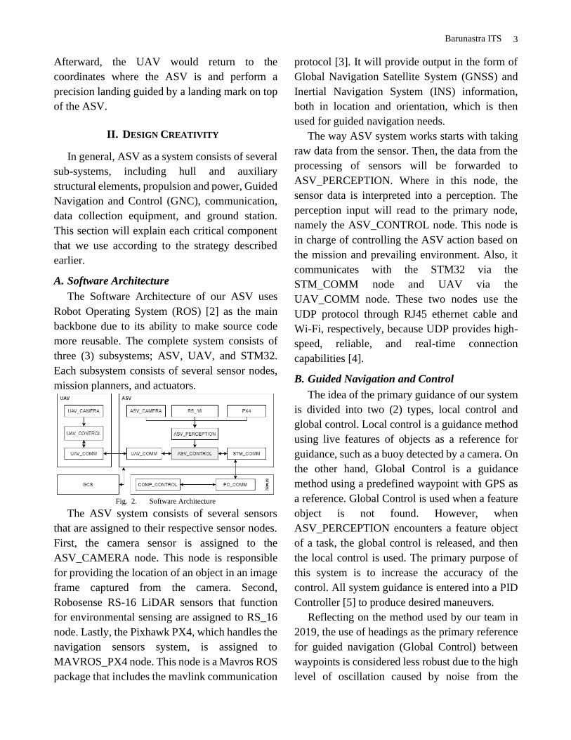
A. Software Architecture
The Software Architecture of our ASV uses
Robot Operating System (ROS) [2] as the main
backbone due to its ability to make source code
more reusable. The complete system consists of
three (3) subsystems; ASV, UAV, and STM32.
Each subsystem consists of several sensor nodes,
mission planners, and actuators.
Fig. 2. Software Architecture
The ASV system consists of several sensors
that are assigned to their respective sensor nodes.
First, the camera sensor is assigned to the
ASV_CAMERA node. This node is responsible
for providing the location of an object in an image
frame captured from the camera. Second,
Robosense RS-16 LiDAR sensors that function
for environmental sensing are assigned to RS_16
node. Lastly, the Pixhawk PX4, which handles the
navigation sensors system, is assigned to
MAVROS_PX4 node. This node is a Mavros ROS
package that includes the mavlink communication
protocol [3]. It will provide output in the form of
Global Navigation Satellite System (GNSS) and
Inertial Navigation System (INS) information,
both in location and orientation, which is then
used for guided navigation needs.
The way ASV system works starts with taking
raw data from the sensor. Then, the data from the
processing of sensors will be forwarded to
ASV_PERCEPTION. Where in this node, the
sensor data is interpreted into a perception. The
perception input will read to the primary node,
namely the ASV_CONTROL node. This node is
in charge of controlling the ASV action based on
the mission and prevailing environment. Also, it
communicates with the STM32 via the
STM_COMM node and UAV via the
UAV_COMM node. These two nodes use the
UDP protocol through RJ45 ethernet cable and
Wi-Fi, respectively, because UDP provides high-
speed, reliable, and real-time connection
capabilities [4].
B. Guided Navigation and Control
The idea of the primary guidance of our system
is divided into two (2) types, local control and
global control. Local control is a guidance method
using live features of objects as a reference for
guidance, such as a buoy detected by a camera. On
the other hand, Global Control is a guidance
method using a predefined waypoint with GPS as
a reference. Global Control is used when a feature
object is not found. However, when
ASV_PERCEPTION encounters a feature object
of a task, the global control is released, and then
the local control is used. The primary purpose of
this system is to increase the accuracy of the
control. All system guidance is entered into a PID
Controller [5] to produce desired maneuvers.
Reflecting on the method used by our team in
2019, the use of headings as the primary reference
for guided navigation (Global Control) between
waypoints is considered less robust due to the high
level of oscillation caused by noise from the

4
Barunastra ITS
heading sensor and the harshness of the wind at the
venue. Also, in several cases that were already
obtained, ASV could not reach a waypoint. It only
circulated at one waypoint because the desired
heading control exceeds the maximum physical
limit of the ASV (Fig. 3). This happened due to the
error heading exceeds the control heading.
Fig. 3. Waypoint Navigation Issue
To solve this problem, the error against the
waypoint is redefined from the heading error only
to the combination of heading error and the
perpendicular distance of ASV to the waypoint
line. So, ASV is expected to maneuver, as shown
in Figure 4.
Fig. 4. The path from Waypoint A to B. Left for the 2019's algorithm, right
for our proposed algorithm
C. Hull Design and Characteristic
In 2019, the hull design of the ASV was
considered less stable, especially if its waves hit it.
Therefore, in IRC 2021, SWATH-type was chosen
to solve this problem. SWATH is a type of
catamaran hull whose demi hull shapes like a
cylinder beneath the water surface. It is connected
to the boat deck area by a pair of thin struts. There
are several advantages of using this type of hull.
Fig. 5. Proposed Roboboat Design
First, it decreases wave-making resistance. The
main reason is that the SWATH struts produce
relatively small waves when the ASV moves on
the water. Based on the venue characteristic, this
would be very beneficial. The venue, a pool,
would make the resulting waves spread out to the
pool's edge. These waves would later bounce off
and return to the ASV, resulting in motion
disturbances that could interfere with the sensor's
performance (camera). Therefore, the ASV's hull
must produce minor possible waves [6].
Second, it has good maneuverability and
course-keeping ability. It was shown based on
research that SWATH has a smaller turning radius
due to the generally shorter hull length of the
SWATH. In addition, there is a considerable
distance between the hull and the propeller. It
directs more water flow to the propeller, providing
a significant turning moment even at low speed
[6].
Last, it decreases motion in waves. The wave
disturbances are relatively minor because most of
the hull is submerged underwater, so the ASV's
center of buoyancy is much lower. With proper
placement of the components, the SWATH-type
hull can remain stable in extreme conditions such
as high waves [6]. Hence, the proposed Nala
Poseidon is considered superior to the previous
Nala G4, enhancing the probability of
accomplishing all missions.
Stability would affect the ability of a vessel to
return to its equilibrium point after receiving
external forces [7]. If the ASV's stability is
inadequate, it might experience several problems,

5
Barunastra ITS
such as bad trim (tilting front and back), bad heel
(tilting left and right), or capsizing. The main
factor that determines the stability of the ASV is its
weight distribution. The placement of the
components is arranged such that the center of
gravity is low. This could be achieved by placing
components with a significant weight as low as
possible. Proper placement of the ASV's
components results in the well-trimmed ASV.
In order to do so, the placement of the
components must be viewed based on three (3)
reference axis, namely longitudinal (x-axis),
transverse (y-axis), and vertical (z-axis).
The zero (0) point of x-axis is defined at the
ASV's stern. Meanwhile, the zero (0) points of y-
axis and z-axis are defined at the ASV's centerline
and baseline, respectively. The components
installed are batteries, ballast, laptop, and electrical
system. The Maxsurf Stability software simplifies
the calculation process to see the trim results due
to component distribution [7].
D. ASV Perception
For the Computer Vision, a custom object
detection model needs to be created to detect
objects in the IRC 2021 missions. YOLOv4
architecture was used to build our custom object
detection model. YOLOv4 is an improved version
of YOLOv3 [8], which we used in IRC 2019.
Our custom model used transfer learning by
freezing the extractor feature layer in the YOLOv4
architecture [9]. The dataset used to train the
custom model has similar shapes to the COCO
dataset that YOLOv4 was pretrained. Therefore, it
is possible to perform transfer learning using our
IRC 2021 objects dataset. With transfer learning, it
is expected to increase the mean Accuracy
Perfomance (mAP) level within a shorter amount
of training time and a relatively small dataset on a
custom model.
Fig. 6. Dataset Sample used to train the custom model
On the other hand, the object's distance can be
obtained by combining the Object Detection
results with LiDAR Segmentation. This can be
achieved by finding the horizontal angle of an
object captured by the camera that would be
projected to LiDAR using (Eq. 1).
𝑓(𝑥) = 𝑑𝑖𝑎𝑔𝑜𝑛𝑎𝑙𝐹0𝑉(2𝑥−𝑤𝑖𝑑𝑡ℎ)
2√𝑤𝑖𝑑𝑡ℎ2+ℎ𝑒𝑖𝑔ℎ𝑡2 (1)
Our LiDAR Segmentation method was inspired
by Morphological Transformations [10]. This
process is done by converting point cloud's points
to pixel points in an image. Then, OpenCV [11]
Morphological Transformations is performed to
the image. As a result, the neighboring pixels
would merge.
E. Acoustic Signal Processing
Acoustic signal processing is a method of
completing an acoustic docking mission. Our
approach resembles the working system of the
human ear, which likens two hydrophones to a
pair of human ears. The working principle of this
method is by capturing the signal from the active
beacon and performing the Time Difference of
Arrival (TDOA). TDOA method as the basis for
processing the captured signal is chosen with
some context adjustments and modifications [12],
[13], [14]. The way to find the location of the
acoustic signal is to estimate the angular direction
received by the hydrophone. Then, the location is
estimated by the accumulated angular direction of
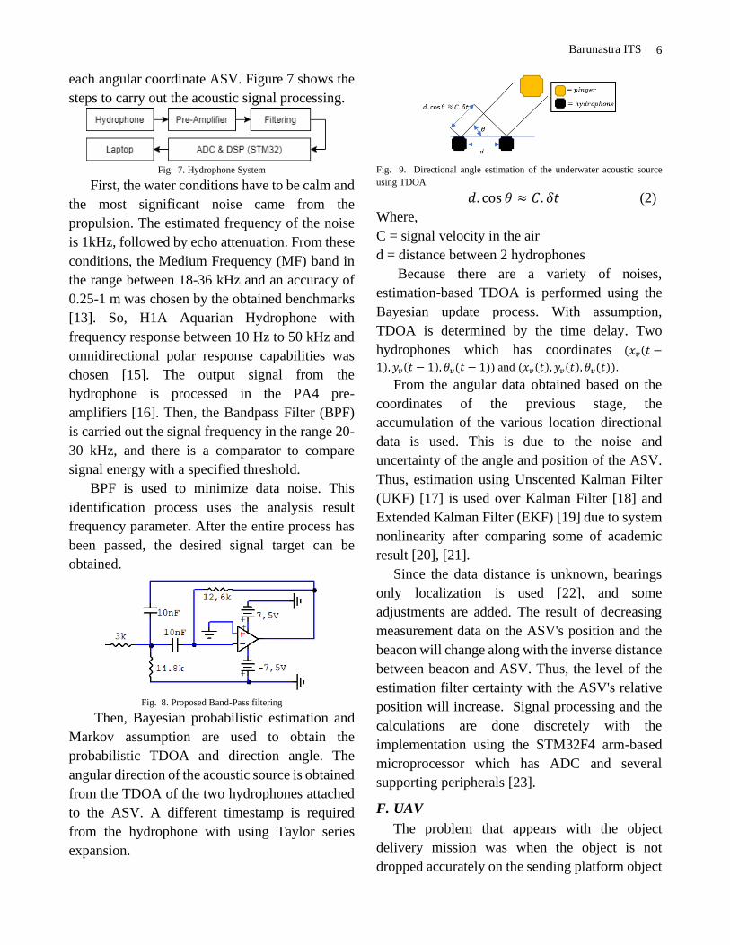
6
Barunastra ITS
each angular coordinate ASV. Figure 7 shows the
steps to carry out the acoustic signal processing.
Fig. 7. Hydrophone System
First, the water conditions have to be calm and
the most significant noise came from the
propulsion. The estimated frequency of the noise
is 1kHz, followed by echo attenuation. From these
conditions, the Medium Frequency (MF) band in
the range between 18-36 kHz and an accuracy of
0.25-1 m was chosen by the obtained benchmarks
[13]. So, H1A Aquarian Hydrophone with
frequency response between 10 Hz to 50 kHz and
omnidirectional polar response capabilities was
chosen [15]. The output signal from the
hydrophone is processed in the PA4 pre-
amplifiers [16]. Then, the Bandpass Filter (BPF)
is carried out the signal frequency in the range 20-
30 kHz, and there is a comparator to compare
signal energy with a specified threshold.
BPF is used to minimize data noise. This
identification process uses the analysis result
frequency parameter. After the entire process has
been passed, the desired signal target can be
obtained.
Fig. 8. Proposed Band-Pass filtering
Then, Bayesian probabilistic estimation and
Markov assumption are used to obtain the
probabilistic TDOA and direction angle. The
angular direction of the acoustic source is obtained
from the TDOA of the two hydrophones attached
to the ASV. A different timestamp is required
from the hydrophone with using Taylor series
expansion.
Fig. 9. Directional angle estimation of the underwater acoustic source
using TDOA
𝑑. cos 𝜃 ≈ 𝐶. 𝛿𝑡 (2)
Where,
C = signal velocity in the air
d = distance between 2 hydrophones
Because there are a variety of noises,
estimation-based TDOA is performed using the
Bayesian update process. With assumption,
TDOA is determined by the time delay. Two
hydrophones which has coordinates (𝑥𝑣(𝑡 −
1), 𝑦𝑣(𝑡 − 1), 𝜃𝑣(𝑡 − 1)) and (𝑥𝑣(𝑡), 𝑦𝑣(𝑡), 𝜃𝑣(𝑡)).
From the angular data obtained based on the
coordinates of the previous stage, the
accumulation of the various location directional
data is used. This is due to the noise and
uncertainty of the angle and position of the ASV.
Thus, estimation using Unscented Kalman Filter
(UKF) [17] is used over Kalman Filter [18] and
Extended Kalman Filter (EKF) [19] due to system
nonlinearity after comparing some of academic
result [20], [21].
Since the data distance is unknown, bearings
only localization is used [22], and some
adjustments are added. The result of decreasing
measurement data on the ASV's position and the
beacon will change along with the inverse distance
between beacon and ASV. Thus, the level of the
estimation filter certainty with the ASV's relative
position will increase. Signal processing and the
calculations are done discretely with the
implementation using the STM32F4 arm-based
microprocessor which has ADC and several
supporting peripherals [23].
F. UAV
The problem that appears with the object
delivery mission was when the object is not
dropped accurately on the sending platform object

7
Barunastra ITS
due to noise on the GNSS reading sensor. To solve
this problem, the UAV would be controlled based
on information obtained from the camera, not
from the GNSS sensor when the drone has
approached setpoint object delivery.
The UAV used Pixhawk 2.1 Flight Controller.
A mini-PC (Raspberry Pi 4) is attached to the
UAV, acting as an onboard computing platform.
The mini-PC would be responsible for image
processing and controlling the UAV. A camera is
also attached to the UAV to provide an image
feed.
The Raspberry Pi 4 was selected as the onboard
mini-PC due to its lightweight characteristics. But,
Raspberry Pi 4 is limited in computational
resources [24]. So, a computationally light image
processing method for detecting object delivery
marker and landing platform on top of the ASV is
required. With that in mind, a conventional image
segmentation method, HSV thresholding with
morphological transformation, is implemented
[10]. With the same method, the landing platform
in ASV can also be detected.
G. Graphic User Interface (GUI)
Graphic User Interface (GUI) for IRC 2021 was
developed using Qt. The main reason is that Qt has
a framework that suits IRC 2021 mission,
especially the signal and slot features [25]. The
GUI helped control system parameter tuning
during research and monitored the state when
ASV is operating.
Fig. 10. ASV Software GUI
H. Simulation
For the purpose of testing our system, VRX
simulation has been forked from the OSRF
GitHub repository to be the base of our simulator
[26]. The physics properties of the simulator were
adjusted according to the characteristics of our
ASV.
Fig. 11. Gazebo Simulation Message Diagram
The package THRUSTER_HANDLER was
created to translate and forward control messages
from ASV_CONTROL to the simulator. The
simulator also publishes sensor messages such as
camera image, LiDAR point clouds, INS, and
GNSS, to which the ASV_PERCEPTION
package would subscribe.
Fig. 12. Gazebo Simulation Window
III. EXPERIMENTAL RESULTS
A. Hull Performance
The 2019 IRC rule used as a reference for the
principal dimensions of this year ASV, as follows: Table 1. Principal Dimension of NALA Poseidon
Principal Dimension
Length 100 cm
Breadth 50.4 cm
Height (Hull Only) 35 cm
Height (Total) 60 cm
Draft 17.5 cm (from baseline)
Displacement 25.61 kg

8
Barunastra ITS
In analyzing the performance, the Nala
Poseidon model is compared with the 2019 IRC
ASV (Nala G4) model. This ASV performance
analysis consists of two (2) major parts: resistance
and seakeeping. For each simulation, each model
is run at 2.4 m/s.
(a) (b)
Fig. 13 (a) (b) Wave Generation Pattern top view comparison between
2021 model (a) and 2019 model (b)
Fig. 14 Wave Generation Pattern side view comparison between 2021
model (Top) and 2019 model (Bottom)
The simulations above show that the 2021
model generated a maximum wave height of 11.33
cm. Meanwhile, the obtained maximum wave
height of the 2019 model is 14.65 cm. It could be
seen that the current model produces a lower
maximum wave height (about 3.35 cm less) than
the previous model.
The height obtained from the Computational
Fluid Dynamic (CFD) analysis is used to observe
the response of the vertical motion in front of the
camera sensor due to the waves generated by the
hull. Response of this movement can be calculated
using Maxsurf Seakeeping Software by finding the
Response Amplitude Operator (RAO) at a certain
point on the ASV. In this simulation, the RAO is
calculated for the front camera position. RAO is a
function that provides the amplitude value of the
oscillatory motion of the vessel due to waves
acting on it [27]. Then, the data from the IRC 2019
and 2021 ASV models are compared. The
following coordinates define the camera position.
Table 2. Coordinate of Camera Position
IRC
Model
Longitudinal
Centre [cm]
Transversal
Centre [cm]
Vertical
Centre [cm]
2021 82.4 0 43.5
2019 82.5 0 50.25
After the RAO is calculated, the camera
sensor's vertical displacement amplitude, velocity
amplitude, and acceleration amplitude can be
calculated. Maxsurf Motion software is used to
calculate these. For the simulation, each ASV
model runs at the same speed. Meanwhile, the
operating wave height value is taken from the
previous CFD analysis. The final analysis result is
obtained as follows: Table 3. Final Analysis Result
The data above shows that the front camera's
displacement and velocity responses of the 2021
ASV model are smaller than 2019 model. So it can
be concluded that the 2021 ASV hull model is
more beneficial for ASV perception sensors [28].
B. Guided Navigation Performance
Using our simulation system, the proposed
algorithm and the previous algorithm were tested
to obtain error data. Figure 14 below shows the
progression of total error over time for the IRC
2019's GNC algorithm and the proposed GNC
algorithm. The total error is defined as the root
sum square of normalized heading error and
perpendicular distance error. The IRC 2019's
GNC algorithm's error was difficult to converge,
and the error remained. Meanwhile, using the
proposed GNC algorithm, the errors can converge
quicker. The image shows the path generated by
the two algorithms (Fig. 16). The ASV follows the

9
Barunastra ITS
defined path closer than the previous algorithm.
The previous algorithm produced a mean of total
errors 0.3121, whereas the proposed algorithm
produced 0.1589, half the previous algorithm.
Fig. 15. Graphs Data Error
Fig. 16. Figure Path in 2019 and 2021
C. Computer Vision Performance
For the ASV, our object detection model's
performance using various architectures was
tested with inputs from a virtual camera provided
by our gazebo simulator. These tests were ran
using a Mobile Nvidia RTX 2060 6GB GPU,
which would be the GPU of the PC boarded on the
ASV. Table 5 below shows the comparison
between the architectures. It is observed that
YOLOv4 has a higher level of accuracy and bigger
Frame per Second (FPS) than YOLOv3, which is
better in overall performance than YOLOv3 in
past competitions.
Fig. 17. Object Detection
Table 4. Performance Comparison of Yolo Models
Model mAp FPS TDP
Yolo V3 (IRC 2019) 91.2 16.3 95 W
Yolo V4 92.17 29.1 95 W
Tiny Yolo V4 81.74 147.8 90 W
Tiny Yolo V4 81.74 50.6 45 W
Related distance information from objects
detected by the camera is provided by the result of
LiDAR segmentation. Figure 18 below shows the
segmented point clouds that are limited to 10
meters radius from LiDAR.
Fig. 18. Lidar 2D View and Lidar 3D View
For the UAV, the object delivery marker can be
detected using the method mentioned in section II.
Raspberry Pi 4 managed to obtain a solid 16 FPS.
Fig. 19. UAV Computer Vision GUI
D. Acoustic Signal Processing Performance
MATLAB simulation was used to test the
performance of the proposed acoustic signal
processing method. After running several
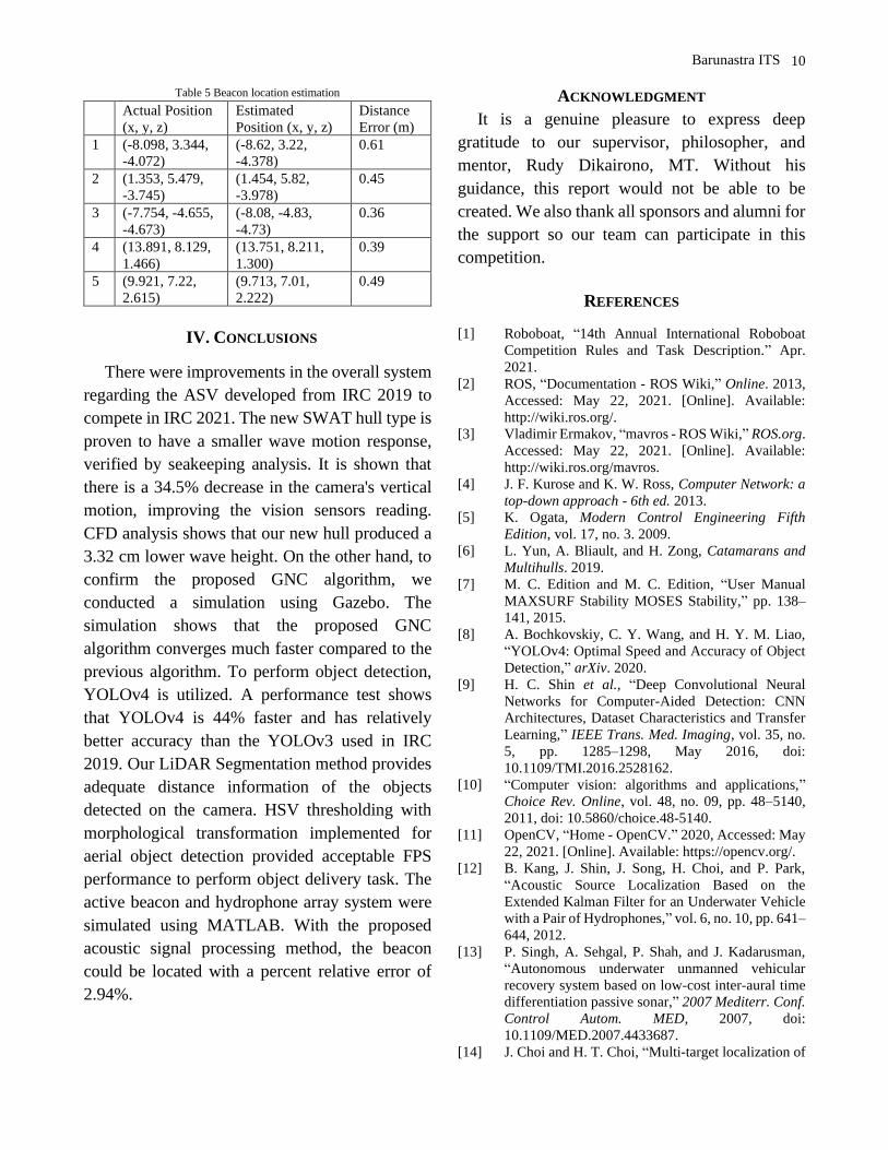
simulations, data in Table 5 were obtained.
Distance error is defined as the Euclidean distance
between the actual and estimated position. It is
observed that this method can estimate the
position of the active beacon with a percent
relative error of 2.94%.
10
Barunastra ITS
Table 5 Beacon location estimation
Actual Position
(x, y, z) Estimated
Position (x, y, z) Distance
Error (m) 1 (-8.098, 3.344,
-4.072) (-8.62, 3.22,
-4.378) 0.61
2 (1.353, 5.479,
-3.745) (1.454, 5.82,
-3.978) 0.45
3 (-7.754, -4.655,
-4.673) (-8.08, -4.83,
-4.73) 0.36
4 (13.891, 8.129,
1.466) (13.751, 8.211,
1.300) 0.39
5 (9.921, 7.22,
2.615) (9.713, 7.01,
2.222) 0.49
IV. CONCLUSIONS
There were improvements in the overall system
regarding the ASV developed from IRC 2019 to
compete in IRC 2021. The new SWAT hull type is
proven to have a smaller wave motion response,
verified by seakeeping analysis. It is shown that
there is a 34.5% decrease in the camera's vertical
motion, improving the vision sensors reading.
CFD analysis shows that our new hull produced a
3.32 cm lower wave height. On the other hand, to
confirm the proposed GNC algorithm, we
conducted a simulation using Gazebo. The
simulation shows that the proposed GNC
algorithm converges much faster compared to the
previous algorithm. To perform object detection,
YOLOv4 is utilized. A performance test shows
that YOLOv4 is 44% faster and has relatively
better accuracy than the YOLOv3 used in IRC
2019. Our LiDAR Segmentation method provides
adequate distance information of the objects
detected on the camera. HSV thresholding with
morphological transformation implemented for
aerial object detection provided acceptable FPS
performance to perform object delivery task. The
active beacon and hydrophone array system were
simulated using MATLAB. With the proposed
acoustic signal processing method, the beacon
could be located with a percent relative error of
2.94%.
ACKNOWLEDGMENT
It is a genuine pleasure to express deep
gratitude to our supervisor, philosopher, and
mentor, Rudy Dikairono, MT. Without his
guidance, this report would not be able to be
created. We also thank all sponsors and alumni for
the support so our team can participate in this
competition.
REFERENCES
[1] Roboboat, “14th Annual International Roboboat
Competition Rules and Task Description.” Apr.
2021.
[2] ROS, “Documentation - ROS Wiki,” Online. 2013,
Accessed: May 22, 2021. [Online]. Available:
http://wiki.ros.org/.
[3] Vladimir Ermakov, “mavros - ROS Wiki,” ROS.org.
Accessed: May 22, 2021. [Online]. Available:
http://wiki.ros.org/mavros.
[4] J. F. Kurose and K. W. Ross, Computer Network: a
top-down approach - 6th ed. 2013.
[5] K. Ogata, Modern Control Engineering Fifth
Edition, vol. 17, no. 3. 2009.
[6] L. Yun, A. Bliault, and H. Zong, Catamarans and
Multihulls. 2019.
[7] M. C. Edition and M. C. Edition, “User Manual
MAXSURF Stability MOSES Stability,” pp. 138–
141, 2015.
[8] A. Bochkovskiy, C. Y. Wang, and H. Y. M. Liao,
“YOLOv4: Optimal Speed and Accuracy of Object
Detection,” arXiv. 2020.
[9] H. C. Shin et al., “Deep Convolutional Neural
Networks for Computer-Aided Detection: CNN
Architectures, Dataset Characteristics and Transfer
Learning,” IEEE Trans. Med. Imaging, vol. 35, no.
5, pp. 1285–1298, May 2016, doi:
10.1109/TMI.2016.2528162.
[10] “Computer vision: algorithms and applications,”
Choice Rev. Online, vol. 48, no. 09, pp. 48–5140,
2011, doi: 10.5860/choice.48-5140.
[11] OpenCV, “Home - OpenCV.” 2020, Accessed: May
22, 2021. [Online]. Available: https://opencv.org/.
[12] B. Kang, J. Shin, J. Song, H. Choi, and P. Park,
“Acoustic Source Localization Based on the
Extended Kalman Filter for an Underwater Vehicle
with a Pair of Hydrophones,” vol. 6, no. 10, pp. 641–
644, 2012.
[13] P. Singh, A. Sehgal, P. Shah, and J. Kadarusman,
“Autonomous underwater unmanned vehicular
recovery system based on low-cost inter-aural time
differentiation passive sonar,” 2007 Mediterr. Conf.
Control Autom. MED, 2007, doi:
10.1109/MED.2007.4433687.
[14] J. Choi and H. T. Choi, “Multi-target localization of

11
Barunastra ITS
underwater acoustic sources based on probabilistic
estimation of direction angle,” MTS/IEEE Ocean.
2015 - Genova Discov. Sustain. Ocean Energy a
New World, pp. 4–9, 2015, doi: 10.1109/OCEANS-
Genova.2015.7271437.
[15] A. A. Products, “H2a-XLR Hydrophone User ’ s
Guide,” Audio.
[16] “PA4 Datasheet,” pp. 3–4.
[17] S. J. Julier and J. K. Uhlmann, “New extension of
the Kalman filter to nonlinear systems,” Signal
Process. Sens. Fusion, Target Recognit. VI, vol.
3068, p. 182, 1997, doi: 10.1117/12.280797.
[18] R. E. Kalman, “A new approach to linear filtering
and prediction problems,” J. Fluids Eng. Trans.
ASME, vol. 82, no. 1, pp. 35–45, 1960, doi:
10.1115/1.3662552.
[19] R. G. Brown and P. Y. . C. Hwang, “Brown R. G.,
Hwang P. Y. C. Introduction to random signals and
applied Kalman filtering: with MATLAB exercises
and solutions //Introduction to random signals and
applied Kalman filtering: with MATLAB exercises
and solutions, by Brown, Robert Grover.; Hwan.”
1997.
[20] E. Dehghan Niri, A. Farhidzadeh, and S. Salamone,
“Adaptive unscented Kalman filter (UKF) for
acoustic emission (AE) source localization in noisy
environment,” Heal. Monit. Struct. Biol. Syst. 2013,
vol. 8695, no. April, p. 869518, 2013, doi:
10.1117/12.2008617.
[21] W. Liu, Y. Liu, and R. Bucknall, “A Robust
Localization Method for Unmanned Surface
Vehicle (USV) Navigation Using Fuzzy Adaptive
Kalman Filtering,” IEEE Access, vol. 7, pp. 46071–
46083, 2019, doi: 10.1109/ACCESS.2019.2909151.
[22] M. C. Deans, “Bearings-Only Localization and
Mapping,” pp. 1–160, 2005.
[23] “Datasheet - production data,” no. STM32F47xx.
2018.
[24] Various, “Raspberry Pi 4 Model B specifications –
Raspberry Pi,” Raspberry Pi Foundation, no.
BCM2711. 2020, [Online]. Available:
https://www.raspberrypi.org/products/raspberry-pi-
4-model-b/specifications/.
[25] T. Q. Company, “Qt | Cross-platform software
development for embedded & desktop.” 2017.
[26] B. Bingham et al., “Toward maritime robotic
simulation in gazebo,” Oct. 2019, doi:
10.23919/OCEANS40490.2019.8962724.
[27] R. Bhattacharya, Dynamics of marine vehicles.
1978.
[28] M. C. Edition and M. C. Edition, “User Manual
MAXSURF Stability MOSES Stability,” 2015.
12
Barunastra ITS
APPENDIX A : COMPONENT
SPECIFICATION
See Figure A and Table A.
APPENDIX B : OUTREACH ACTIVITIES
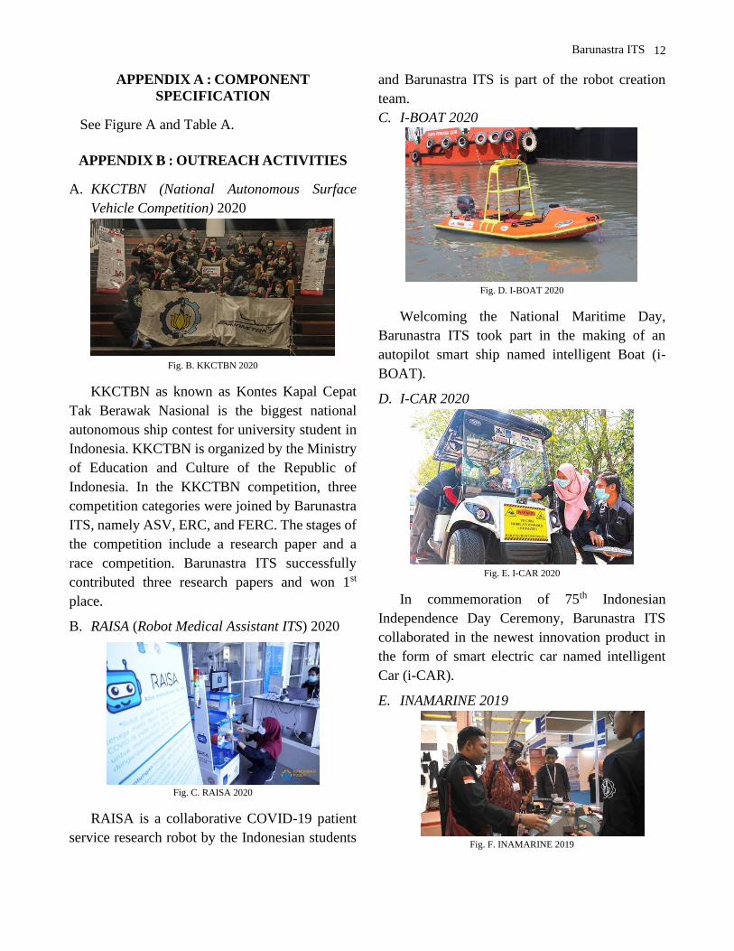
A. KKCTBN (National Autonomous Surface
Vehicle Competition) 2020
Fig. B. KKCTBN 2020
KKCTBN as known as Kontes Kapal Cepat
Tak Berawak Nasional is the biggest national
autonomous ship contest for university student in
Indonesia. KKCTBN is organized by the Ministry
of Education and Culture of the Republic of
Indonesia. In the KKCTBN competition, three
competition categories were joined by Barunastra
ITS, namely ASV, ERC, and FERC. The stages of
the competition include a research paper and a
race competition. Barunastra ITS successfully
contributed three research papers and won 1st
place.
B. RAISA (Robot Medical Assistant ITS) 2020
Fig. C. RAISA 2020
RAISA is a collaborative COVID-19 patient
service research robot by the Indonesian students
and Barunastra ITS is part of the robot creation
team.
C. I-BOAT 2020
Fig. D. I-BOAT 2020
Welcoming the National Maritime Day,
Barunastra ITS took part in the making of an
autopilot smart ship named intelligent Boat (i-
BOAT).
D. I-CAR 2020
Fig. E. I-CAR 2020
In commemoration of 75th Indonesian
Independence Day Ceremony, Barunastra ITS
collaborated in the newest innovation product in
the form of smart electric car named intelligent
Car (i-CAR).
E. INAMARINE 2019
Fig. F. INAMARINE 2019

13
Barunastra ITS
INAMARINE is the 9th Indonesia
International Shipbuilding, Offshore, Marine
Equipment, Machinery & Services Exhibition
2019. It aims to accelerate the growth of the
maritime industry that is being worked on by the
government. Barunastra ITS showcased the
NALA G4 prototype to engage the audience and
raise awareness about maritime issues.
F. IIBS (International ITS Business Summit)
2019
Fig. G. IIBS 2019
IIBS is annual international business event
held by ITS. Barunastra ITS delivered a speech
about the implementation of AI systems that are
applied to our boat prototype.
14
Barunastra ITS
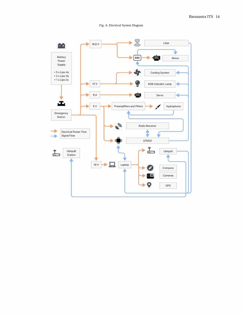
Fig. A. Electrical System Diagram

15
Barunastra ITS
Table. A Component Specification
Components Vendor Model/Type Specification Cost
Autonomous Surface Vehicle Components
ASV Hull Barunastra ITS Swath Hull
Carbon Fibre with
LPP = 100 cm Breadth = 50,4 cm
Height (Hull only) = 35 cm
Total Height = 60 cm Draft = 17,5 cm
Displacement = 25,61 kg
NN
Propulsion Blue Robotics T200 https://bluerobotics.com/store/thrusters/t100
-t200-thrusters/t200-thruster-r2-rp/ $179.00
Propulsion
System Barunastra ITS
Azimuth
Propulsion Stainless Steel NN
Propulsion Mover
(Servo) Savox SC0251MG
https://www.savox-servo.com/Servos-c-
1338/Brushed-Motor-c-1340/Savox-Servo-
SC-0251MG-Digital-DC-Motor-Metal-
Gear/
$38,85
Power System
Turnigy Turnigy 1300mAh
2S 20C Lipo
https://hobbyking.com/en_us/turnigy-
1300mah-2s-20c-lipo-pack.html
$7.24
Onbo Power
Lipo Battery 3s
11.1v 3300mah 25-
50c Onbo Nano
Power
https://www.onbopower.com/m_product/46
9-ONBO-2200mAh-111V-80C-3S1P-
FPVRacing-Dones-quads-Lipo-
BatteryXT60.html
$19,98
Onbo Power
Lipo Battery 4s
148v 6200mah 25c
Onbo Nano Power
https://www.onbopower.com/m_product/13
8-ONBO-25C-4S-148V-6200mAh-
lipo.html
$78.30
Motor Control Blue Robotics Basic ESC https://bluerobotics.com/store/thrusters/spee
d-controllers/besc30-r3/
$27.00
CPU MSI GL63 8SE https://www.msi.com/Laptop/GL63-
8SX/Specification
$1,999.1
Teleoperation Ubiquiti
Network Rocket M5 15 Km range, 350 MBps, 33 Dbm, 5.8Ghz $124.36
INS Pixhawk Pixhawk2.1 http://www.proficnc.com/content/13-
pixhawk2
$379.9
Camera Logitech C930e
https://www.logitech.com/en-
us/products/webcams/c930e-business-
webcam.960-000971.html
$130.00
Radio Transmitter Futaba 10J https://www.rc.futaba.co.jp/english/propo/ai
r/10j.html $399.99
Radio Receiver Futaba R3008SB https://www.rc.futaba.co.jp/english/dl_man
ual/r3008sb_e.pdf
Hydrophone Aquarian
Hydrophone H1A
https://www.aquarianaudio.com/AqAudDoc
s/H1a_manual.pdf
$159.00
Hydrophone
Preamplifier
Aquarian
Hydrophone Pa4 https://www.aquarianaudio.com/pa4.html $94.99
LiDAR Robosense RS LiDAR 16 https://www.robosense.ai/en/rslidar/RS-
LiDAR-16
$5,312.4
Drone System
Aerial Vehicle
Platform Holybro Quadcopter Frame
http://www.holybro.com/product/s500-arf-
v2-frame-kit/ $88,25
16
Barunastra ITS
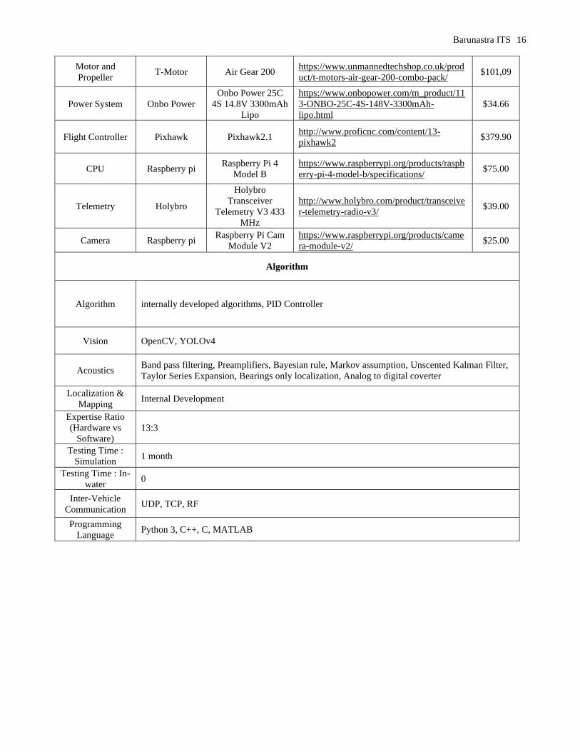
Motor and
Propeller T-Motor Air Gear 200
https://www.unmannedtechshop.co.uk/prod
uct/t-motors-air-gear-200-combo-pack/
$101,09
Power System Onbo Power
Onbo Power 25C
4S 14.8V 3300mAh
Lipo
https://www.onbopower.com/m_product/11
3-ONBO-25C-4S-148V-3300mAh-
lipo.html
$34.66
Flight Controller Pixhawk Pixhawk2.1 http://www.proficnc.com/content/13-
pixhawk2
$379.90
CPU Raspberry pi Raspberry Pi 4
Model B
https://www.raspberrypi.org/products/raspb
erry-pi-4-model-b/specifications/ $75.00
Telemetry Holybro
Holybro
Transceiver
Telemetry V3 433
MHz
http://www.holybro.com/product/transceive
r-telemetry-radio-v3/
$39.00
Camera Raspberry pi Raspberry Pi Cam
Module V2
https://www.raspberrypi.org/products/came
ra-module-v2/
$25.00
Algorithm
Algorithm internally developed algorithms, PID Controller
Vision OpenCV, YOLOv4
Acoustics Band pass filtering, Preamplifiers, Bayesian rule, Markov assumption, Unscented Kalman Filter,
Taylor Series Expansion, Bearings only localization, Analog to digital coverter
Localization &
Mapping Internal Development
Expertise Ratio
(Hardware vs
Software)
13:3
Testing Time :
Simulation 1 month
Testing Time : In-
water 0
Inter-Vehicle
Communication UDP, TCP, RF
Programming
Language Python 3, C++, C, MATLAB


![Independent Technical Evaluation - Microsoft...Independent technical Assessment – Page 3/9 IEA 2 Literature [1] Test report Nr. 875-17-008, Versuche am fischer Verbundanker FIS EM](https://img.pdfslide.org/doc/110x75/6102636f2be8af6a4437ff22/independent-technical-evaluation-microsoft-independent-technical-assessment.jpg)