Embed Size (px)
Citation preview
Piezoelektrizität
Der piezoelektrische Effekt wurde bereits 1880 von den Gebrüdern Curie an natürlichen Kristallen entdeckt. Zu den damals bekannten piezoelektrischen Stoffen zählten Seignette-Salz und Turmalin.Die in den 30er Jahren des 20sten Jahrhunderts für die Herstellung von elektrischen Kondensatoren entwickelten ferroelektrischen Keramiken zeigen ebenfalls piezoelek-trische Eigenschaften.Gezielte Forschung und Materialentwicklung führte zu den heutigen piezokeramischen Werkstoffen mit hohem Wirkungsgrad und Variationsmöglichkeiten der Materi-alparameter in weiten Bereichen.
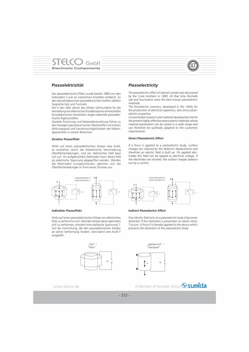
Direkter Piezoeffekt
Wirkt auf einen piezoelektrischen Körper eine Kraft, so entstehen durch die dielektrische Verschiebung Oberfl ächenladungen, und ein elektrisches Feld baut sich auf. An aufgebrachten Elektroden kann dieses Feld als elektrische Spannung abgegriffen werden. Werden die Elektroden kurzgeschlossen, gleichen sich die Oberfl ächenladungen in Form eines Stromes aus.
Piezoelectricity
The piezoelectric effect of natural crystals was discovered by the Curie brothers in 1880. At that time Rochelle salt and tourmaline were the best known piezoelectric materials.The ferroelectric ceramics, developed in the 1930s for the production of electrical capacitors, also show piezo-electric properties.Concentrated research and material development led to the present highly-effective piezoceramic materials whose material parameters can be varied in a wide range and can therefore be optimally adapted to the customers requirements.
Direct Piezoelectric Effect
If a force is applied to a piezoelectric body, surface charges are induced by the dielectric displacement and therefore an electric fi eld is built up. On applied elec-trodes this fi eld can be tapped as electrical voltage. If the electrodes are shorted, the surface charges balance out by a current.
Indirekter Piezoeffekt
Wirkt auf einen piezoelektrischen Körper ein elektrisches Feld, so verformt er sich. Wird der Körper daran gehindert sich zu verformen, entsteht eine elastische Spannung T. Auf die Vorrichtung, die den piezoelektrischen Körper an seiner Verformung hindert, wird damit eine Kraft F ausgeübt.
Indirect Piezoelectric Effect
If an electric fi eld acts on a piezoelectric body it becomes distorted. If this distortion is prevented, an elastic stress T occurs. A force F is thereby applied to the device which prevents the distortion of the piezoelectric body.
F
-+
- + U
F
-
+
- + U
∞ / ∞ F
-
+
- + I
F
-+
- + I
/
UT U
/ /
- 252 -
STELCOSTELCO GmbHGmbHElectronic Components
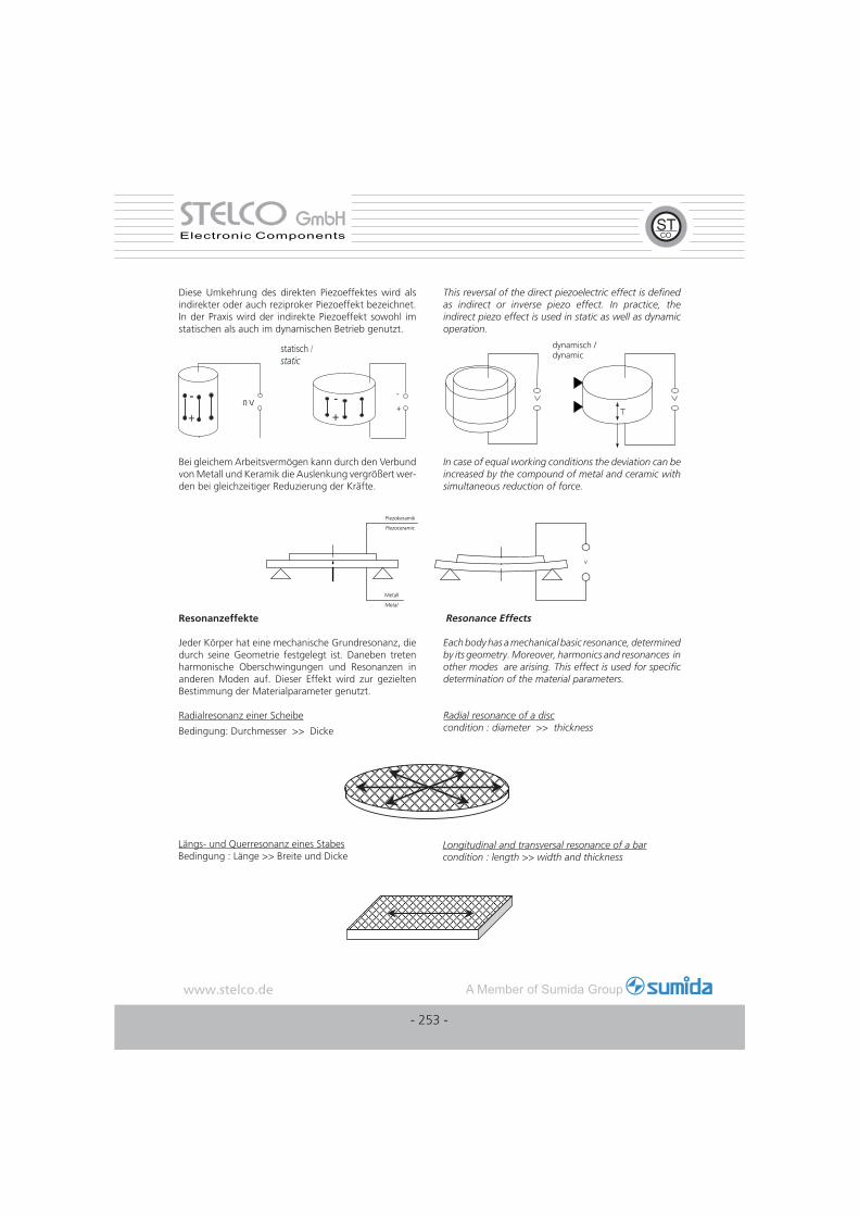
Diese Umkehrung des direkten Piezoeffektes wird als indirekter oder auch reziproker Piezoeffekt bezeichnet. In der Praxis wird der indirekte Piezoeffekt sowohl im statischen als auch im dynamischen Betrieb genutzt.
This reversal of the direct piezoelectric effect is defi ned as indirect or inverse piezo effect. In practice, the indirect piezo effect is used in static as well as dynamic operation.
Bei gleichem Arbeitsvermögen kann durch den Verbund von Metall und Keramik die Auslenkung vergrößert wer-den bei gleichzeitiger Reduzierung der Kräfte.
In case of equal working conditions the deviation can be increased by the compound of metal and ceramic with simultaneous reduction of force.
Resonanzeffekte
Jeder Körper hat eine mechanische Grundresonanz, die durch seine Geometrie festgelegt ist. Daneben treten harmonische Oberschwingungen und Resonanzen in anderen Moden auf. Dieser Effekt wird zur gezielten Bestimmung der Materialparameter genutzt.
Radialresonanz einer Scheibe
Bedingung: Durchmesser >> Dicke
Resonance Effects
Each body has a mechanical basic resonance, determined by its geometry. Moreover, harmonics and resonances in other modes are arising. This effect is used for specifi c determination of the material parameters.
Radial resonance of a disccondition : diameter >> thickness
Längs- und Querresonanz eines StabesBedingung : Länge >> Breite und Dicke
Longitudinal and transversal resonance of a barcondition : length >> width and thickness
0 V-+
-
+-+
/ dynamisch /dynamic
- 253 -
STELCOSTELCO GmbHGmbHElectronic Components

Piezokeramische Werkstoffe
Der Übergang von den "natürlichen" piezoelektri-schen Werkstoffen wie Turmalin und Quarz zu den synthetischen ferroelektrischen Keramiken entwickelte sich in den Jahren nach 1945. Aus den hochwertigen Kondensatorkeramiken auf der Basis Bariumtitanat wurden gezielt piezokeramische Werkstoffe entwickelt, deren Eigenschaften sich über einen weiten Bereich durch Variationen der Materialzusammensetzung be-einfl ussen lassen.
Blei-Zirkonat-Titanat
Die heutigen piezokeramischen Materialien sind meist oxidische Werkstoffe auf der Basis von Bleioxid, Zir-konoxid und Titanoxid. Zur Feinabstimmung der Mate-rialparameter bzw. deren Stabilisierung werden unter anderem Oxide der Metalle Lithium, Magnesium, Zink, Nickel, Mangan, Niob, Antimon oder Strontium zugege-ben. Durch unterschiedliche Mischungsverhältnisse der Grundstoffe, Mahldauer, Kalzination, Formgebung und Sinterung lassen sich die physikalischen Eigenschaften der resultierenden Blei-Zirkonat-Titanat-Verbindungen steuern.
Kristallstruktur und Polarisation
Den Grundaufbau von Blei-Zirkonat-Titanat zeigt die
folgende Abbildung.
Piezoceramic Materials
The change from the "natural" piezoelectric materials such as tourmaline and quartz to the synthetic, artifi cial ferroelectric ceramics occurred in the years following 1945. Piezoceramic materials - whose properties could be infl uenced over a wide range by variations of the material composition - were developed from the high-quality barium-titanate based ceramics used for capacitors.
Lead-zirconate-titanate
Nowadays piezoceramic materials are mostly oxide materials based on lead oxide, zirconium oxide and titanium oxide. Other metal oxides like lithium, magnesium, zinc, nickel, manganese, niobium, antimony or strontium are added for the appropriate adjustment or stabilization of the material parameters. The physical properties of the resulting lead-zirconate-titanate compound can be controlled by different composition ratios of the basic materials, by grinding duration, calcination, shaping and sintering.
Crystal structure and polarization
The fi gure below shows the basic structure of lead-zirconate-titanate.
Die Kristallstruktur leitet sich vom Mineral Perowskit (CaTiO3) her. Oberhalb einer bestimmten Temperatur, der Curie-Temperatur, hat das Gitter kubische Struktur, d.h. es besteht aus regelmäßig angeordneten Sauerstoffok-taedern, in deren Zentrum die Titan- bzw. Zirkonionen sitzen. Beim Unterschreiten der Curie-Temperatur ordnet sich das Gitter zu einem Gemisch rhomboedrischer und tetragonaler Kristalle um. In diesen ist das zentrale Titan bzw. Zirconium nicht mehr im Zentrum, so dass es zu einer Ladungstrennung kommt und damit zur Ausbildung elektrischer Dipole.
The crystalline structure is derived from the mineral perovskite (CaTiO3). Above a specifi c temperature, called Curie temperature, the lattice has a cubic structure, that means it consists of regularly arranged oxygen octahedra in the center of which the titanium resp. zirconium is placed. Below the Curie temperature the lattice structure reorders to a mixture of rhombohedral and tetragonal cystals in which the central titanium resp. zirconium is no longer placed in the center and so a separation of charges takes place and electrical dipoles are formed.
- 254 -
STELCOSTELCO GmbHGmbHElectronic Components
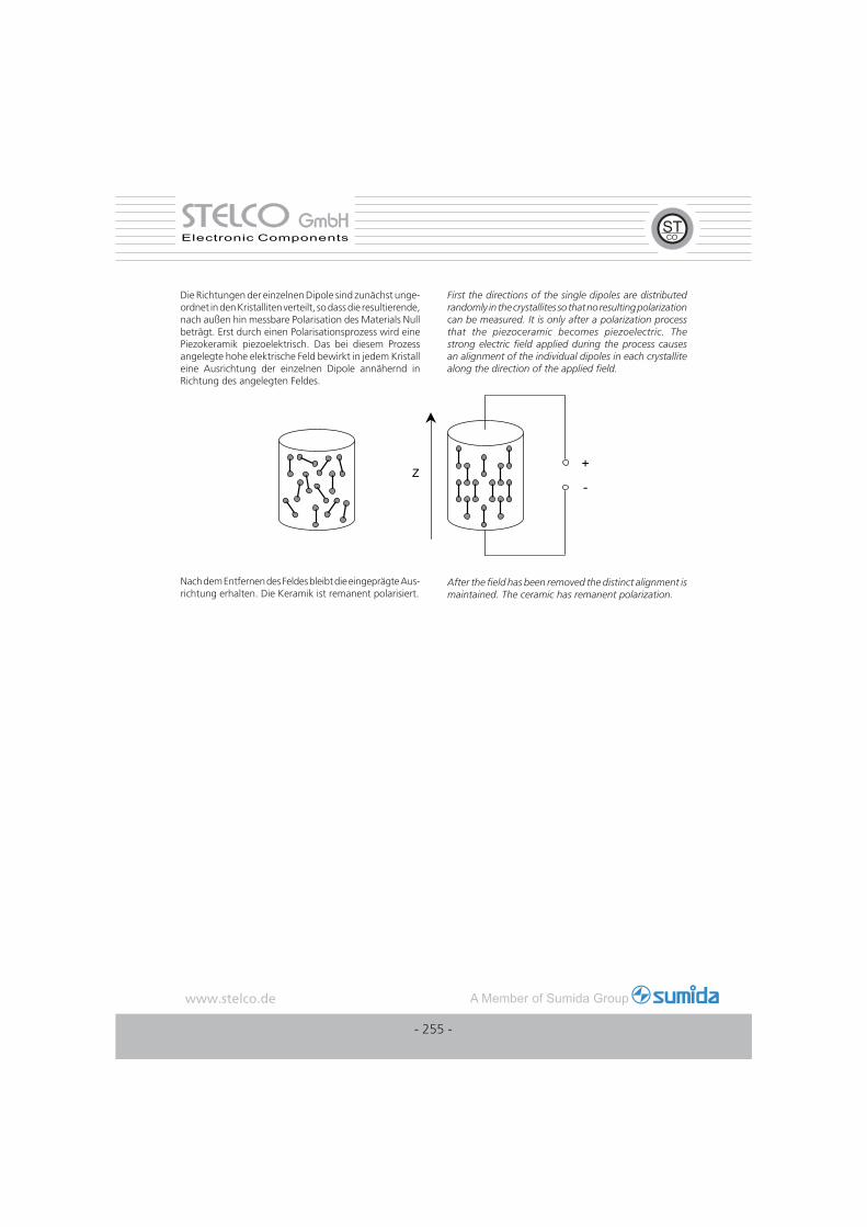
Die Richtungen der einzelnen Dipole sind zunächst unge-ordnet in den Kristalliten verteilt, so dass die resultierende, nach außen hin messbare Polarisation des Materials Null beträgt. Erst durch einen Polarisationsprozess wird eine Piezokeramik piezoelektrisch. Das bei diesem Prozess angelegte hohe elektrische Feld bewirkt in jedem Kristall eine Ausrichtung der einzelnen Dipole annähernd in Richtung des angelegten Feldes.
First the directions of the single dipoles are distributed randomly in the crystallites so that no resulting polarization can be measured. It is only after a polarization process that the piezoceramic becomes piezoelectric. The strong electric fi eld applied during the process causes an alignment of the individual dipoles in each crystallite along the direction of the applied fi eld.
Nach dem Entfernen des Feldes bleibt die eingeprägte Aus-richtung erhalten. Die Keramik ist remanent polarisiert.
After the fi eld has been removed the distinct alignment is maintained. The ceramic has remanent polarization.
+
- Z
- 255 -
STELCOSTELCO GmbHGmbHElectronic Components
Piezoelektrische Grundgleichun-gen und Defi nitionen
Koordinatensystem und Indizierung
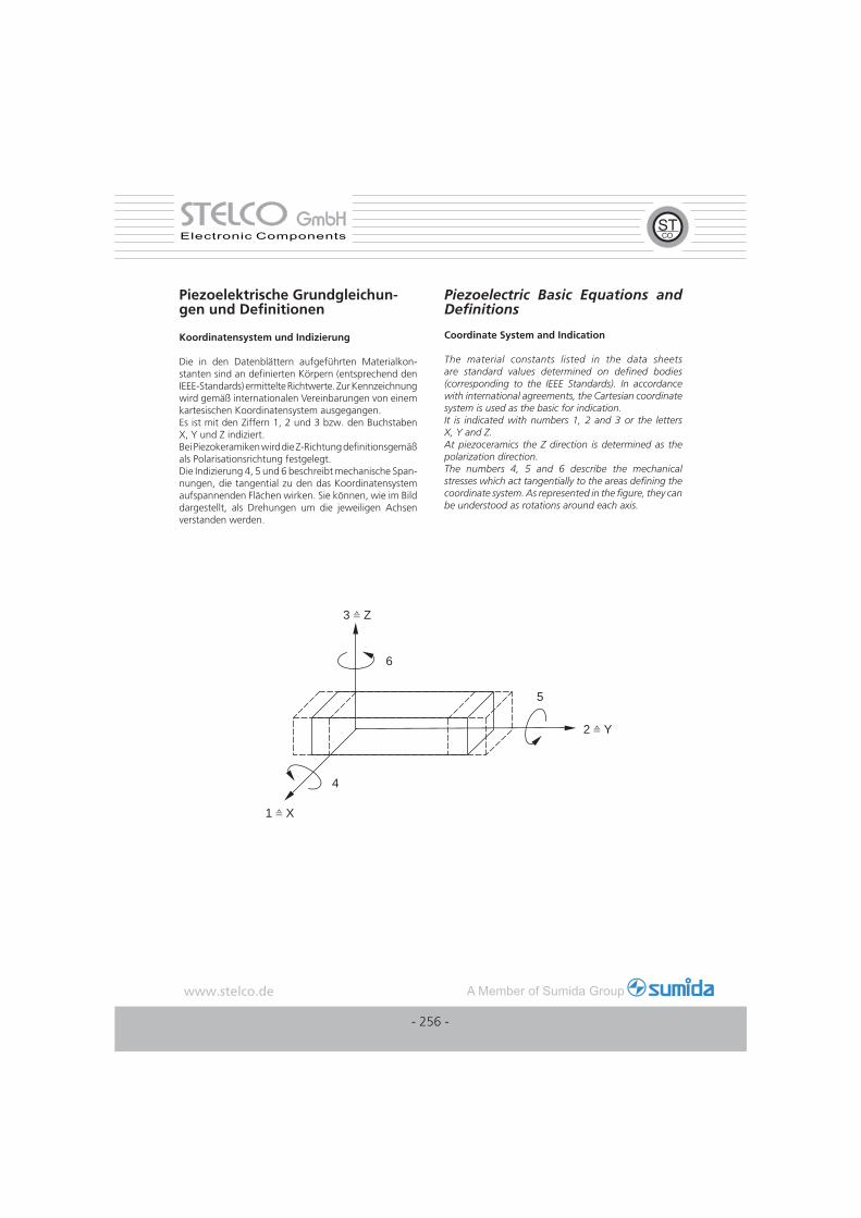
Die in den Datenblättern aufgeführten Materialkon-stanten sind an defi nierten Körpern (entsprechend den IEEE-Standards) ermittelte Richtwerte. Zur Kennzeichnung wird gemäß internationalen Vereinbarungen von einem kartesischen Koordinatensystem ausgegangen. Es ist mit den Ziffern 1, 2 und 3 bzw. den Buchstaben X, Y und Z indiziert.Bei Piezokeramiken wird die Z-Richtung defi nitionsgemäß als Polarisationsrichtung festgelegt.Die Indizierung 4, 5 und 6 beschreibt mechanische Span-nungen, die tangential zu den das Koordinatensystem aufspannenden Flächen wirken. Sie können, wie im Bild dargestellt, als Drehungen um die jeweiligen Achsen verstanden werden.
Piezoelectric Basic Equations and Defi nitions
Coordinate System and Indication
The material constants listed in the data sheets are standard values determined on defi ned bodies (corresponding to the IEEE Standards). In accordance with international agreements, the Cartesian coordinate system is used as the basic for indication.It is indicated with numbers 1, 2 and 3 or the letters X, Y and Z.At piezoceramics the Z direction is determined as the polarization direction.The numbers 4, 5 and 6 describe the mechanical stresses which act tangentially to the areas defi ning the coordinate system. As represented in the fi gure, they can be understood as rotations around each axis.
3 Z
1 X
2 Y
6
4
5
- 256 -
STELCOSTELCO GmbHGmbHElectronic Components
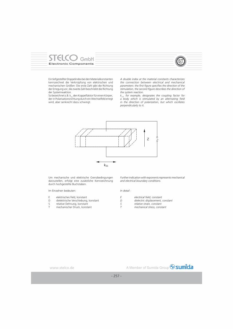
Ein tiefgestellter Doppelindex bei den Materialkonstanten kennzeichnet die Verknüpfung von elektrischen und mechanischen Größen: Die erste Zahl gibt die Richtung der Erregung vor, die zweite Zahl beschreibt die Richtung der Systemreaktion.So bezeichnet z.B. k31 den Koppelfaktor für einen Körper, der in Polarisationsrichtung durch ein Wechselfeld erregt wird, aber senkrecht dazu schwingt.
A double index at the material constants characterizes the connection between electrical and mechanical parameters: the fi rst fi gure specifi es the direction of the stimulation, the second fi gure describes the direction of the system reaction.k31, for example, designates the coupling factor for a body which is stimulated by an alternating fi eld in the direction of polarization, but which oscillates perpendicularly to it.
Z ∼
k31
Um mechanische und elektrische Grenzbedingungen darzustellen, erfolgt eine zusätzliche Kennzeichnung durch hochgestellte Buchstaben.
Im Einzelnen bedeuten:
E elektrisches Feld, konstantD dielektrische Verschiebung, konstantS relative Dehnung, konstant T mechanischer Druck, konstant
Further indication with exponents represents mechanical and electrical boundary conditions.
In detail :
E electrical fi eld, constantD dielectric displacement, constantS relative strain, constantT mechanical stress, constant
- 257 -
STELCOSTELCO GmbHGmbHElectronic Components
Piezoelektrische Gleichungen
Die gesamte Thermodynamik piezoelektrischer Werkstof-fe hier zu beschreiben, würde den Rahmen bei weitem sprengen. Die Phänomenologie ist unter anderem in /6/ beschrieben. Hier sollen nur kurz die Grundlagen angedeutet werden.Ausgehend von thermodynamischen Grundgleichungen kann ein Set von Gleichungen abgeleitet werden, das den Zustand eines piezoelektrischen Körpers eindeutig beschreibt. Für alle dielektrische Materialien gilt:
Piezoelectric Equations
It would be far behond the scope of this catalogue to give a complete description of the thermodynamic of piezoelectric materials. The phenomenology is described for example in reference /6/. Here only a basic outline can be given. Starting with basic equations of thermodynamics a set of equations can be derivated to completely describe the state of a piezoelectric body.
All dielectric materials follow:
Die gesamte in dem piezoelektrischen Körper gespeicherte Energie kann als innere Energie U beschrieben werden. Die Änderung der inneren Energie kann nach Gibbs bestimmt werden mit:
The total energy stored in the piezoelectric body can be described as the internal energy U . The change of this internal energy can be determined acc. to Gibbs:
U Innere Energie Θ Temperatur δ Entropiedichte E elektrisches Feld D elektrische Flußdichte T mechanische Spannung S Deformation
Der Term Θ dσ beschreibt die in dem System enthaltene thermische Energie, Ei dD die elektrische Feldenergie und Tλ dSλ die mechanische Deformationsenergie.
U internal energy Θ temperature δ entropy density E electrical fi eld D electrical fl ux density T mechanical stress S deformation
The term Θ dσ describes the thermal energy stored in the system, Ei dD the electrical fi eld energy, and Tλ dSλ the mechanical deformation energy.
r r rD E P= +ε0
dU d E dD T dSi i= + +Θ σ λ λ
formationDe-
thermoplastische Eigenschaften
piez
oele
ktris
che
Eige
nsch
afte
n
SpannungT
S S
di
-ekk
pyroelektrische Eigenschaften
Entropie
-
ei ip
i
Temperatur
C
Feldstärke
Flußdichte
dkDi
ik
Ek
kp
-
- 258 -
STELCOSTELCO GmbHGmbHElectronic Components
Skalare Größen wie die Temperatur sind richtungsunab-hängig, andere wie die Feldstärke sind richtungsabhängig. Daher sind auch die Beziehungen richtungsabhängig und werden als Tensoren verschiedener Grade oder Matrizen dargestellt. Aus diesen Grundgleichungen können die jeweils interessierenden Beziehungen her-geleitet werden.
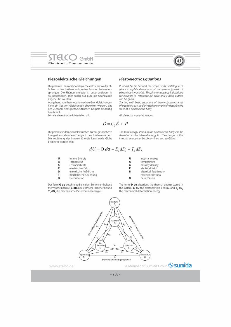
Anschaulich werden die Materialkonstanten und ihr Zusammenhang zwischen unabhängigen Zustandsgrößen Temperatur, Feldstärke und mechanischer Spannung und den abhängigen Größen Flußdichte, Deformation und Entropie in dem Diagramm nach Heckman dargestellt.
Praktische Bedeutung hat insbesondere der Koppelfaktor, der den direkten Vergleich verschiedener Materialien erlaubt. Er beschreibt die Fähigkeit eines Materials, elek-trische Energie in mechanische Energie umzuwandeln und umgekehrt. Der Zusammenhang zu den bereits defi nierten Größen der Grundgleichungen lautet allgemein:
Scalar units like temperature are independent of direction, others like fi eld strength are depending on direction. Therefore, all the relations as well are depending on direction and are therefore represen-ted by tensors of different grade or matrix notation. All interesting relations can be deduced from these basic equations.
The material constants and their relation between the independent variable temperature, fi eld strength and mechanical stress and the dependent units fl ux density, deformation and entropy can be visualized in a diagram acc. to Heckman.
In practice especially the coupling factor is very important, which allows a direct comparison of different materials. It describes the ability of a material to transform electri-cal energy into mechanical energy and vice versa. The connection with the parameters of the basic equations already described is as follows:
Bestimmung der piezokeramischen Material-parameter
Grundsätzlich muss unterschieden werden zwischen Messungen bei geringen Feldstärken (<1V/mm) im Kleinsignalbetrieb und Messungen bei hohen Feldstärken (>100V/mm) im Großsignalbetrieb.
Kleinsignalmessungen
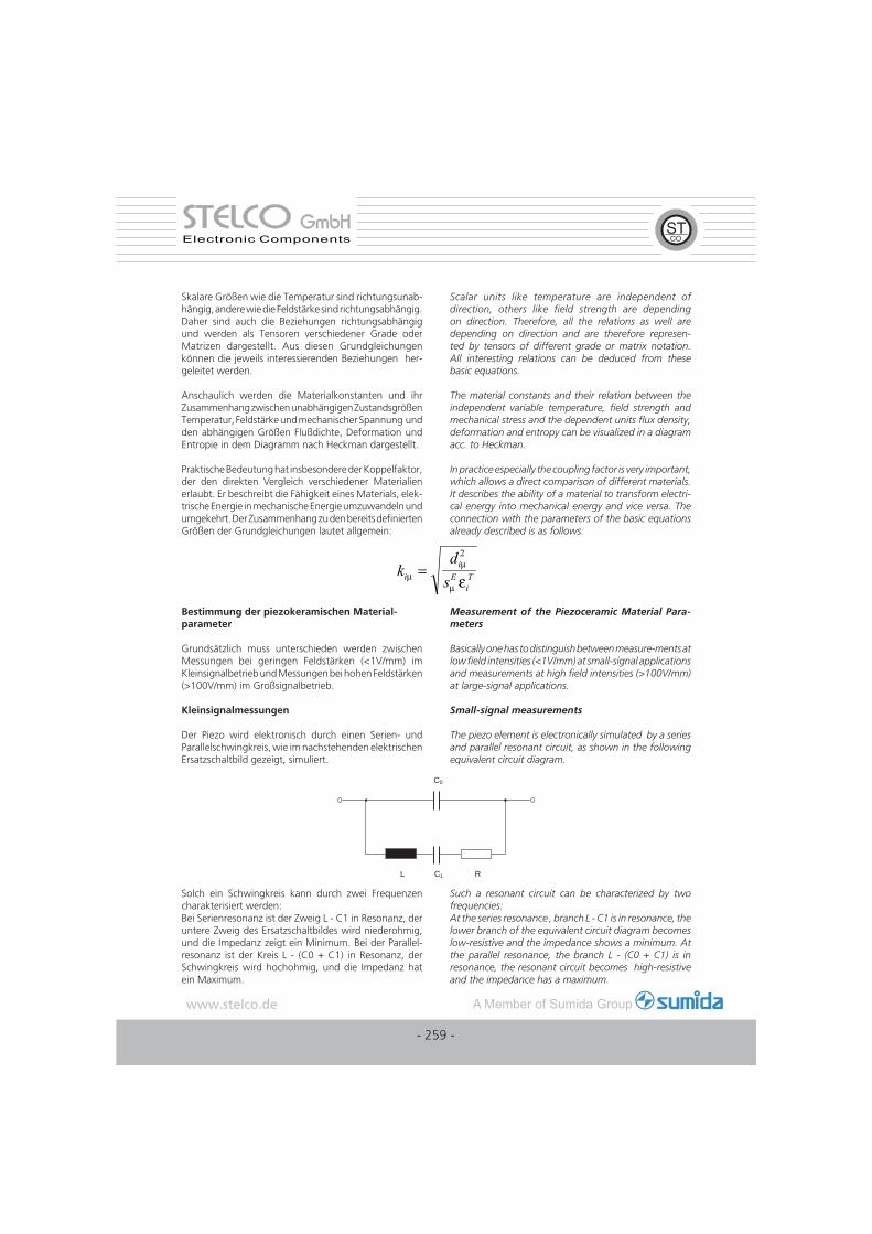
Der Piezo wird elektronisch durch einen Serien- und Parallelschwingkreis, wie im nachstehenden elektrischen Ersatzschaltbild gezeigt, simuliert.
Measurement of the Piezoceramic Material Para-meters
Basically one has to distinguish between measure-ments at low fi eld intensities (<1V/mm) at small-signal applications and measurements at high fi eld intensities (>100V/mm) at large-signal applications.
Small-signal measurements
The piezo element is electronically simulated by a series and parallel resonant circuit, as shown in the following equivalent circuit diagram.
L C1 R
C0
Solch ein Schwingkreis kann durch zwei Frequenzen charakterisiert werden:Bei Serienresonanz ist der Zweig L - C1 in Resonanz, der untere Zweig des Ersatzschaltbildes wird niederohmig, und die Impedanz zeigt ein Minimum. Bei der Parallel-resonanz ist der Kreis L - (C0 + C1) in Resonanz, der Schwingkreis wird hochohmig, und die Impedanz hat ein Maximum.
Such a resonant circuit can be characterized by two frequencies:At the series resonance , branch L - C1 is in resonance, the lower branch of the equivalent circuit diagram becomes low-resistive and the impedance shows a minimum. At the parallel resonance, the branch L - (C0 + C1) is in resonance, the resonant circuit becomes high-resistive and the impedance has a maximum.
kd
sii
EiTμ
μ
μ ε=
2
- 259 -
STELCOSTELCO GmbHGmbHElectronic Components
Physikalische Größe / Physical parameter Elektrische Größe / Electrical parameter
Masse / Mass Induktivität / Inductance
Elastizität / Elasticity Serienkondensator / Series capacitor
Mechanische Verluste / Mechanical losses Widerstand / Resistor
Freie Kapazität / Free capacitance Parallelkondensator / Parallel capacitor
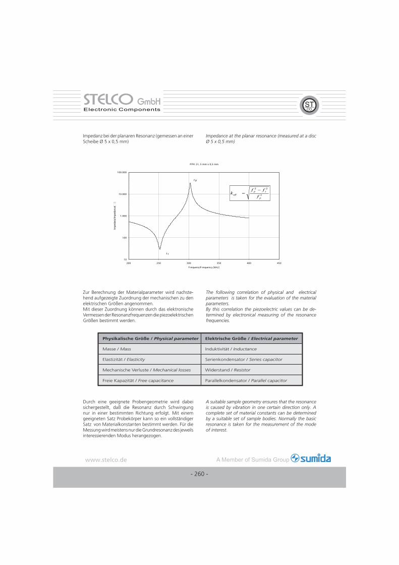
Impedanz bei der planaren Resonanz (gemessen an einer Scheibe Ø 5 x 0,5 mm)
Impedance at the planar resonance (measured at a disc Ø 5 x 0,5 mm)
Zur Berechnung der Materialparameter wird nachste-hend aufgezeigte Zuordnung der mechanischen zu den elektrischen Größen angenommen.Mit dieser Zuordnung können durch das elektronische Vermessen der Resonanzfrequenzen die piezoelektrischen Größen bestimmt werden.
The following correlation of physical and electrical parameters is taken for the evaluation of the material parameters.By this correlation the piezoelectric values can be de-termined by electronical measuring of the resonance frequencies.
Durch eine geeignete Probengeometrie wird dabei sichergestellt, daß die Resonanz durch Schwingung nur in einer bestimmten Richtung erfolgt. Mit einem geeigneten Satz Probekörper kann so ein vollständiger Satz von Materialkonstanten bestimmt werden. Für die Messung wird meistens nur die Grundresonanz des jeweils interessierenden Modus herangezogen.
A suitable sample geometry ensures that the resonance is caused by vibration in one certain direction only. A complete set of material constants can be determined by a suitable set of sample bodies. Normally the basic resonance is taken for the measurement of the mode of interest.
P P K 21, 5 mm x 0,5 mm
10
100
1.000
10.000
100.000
200 250 300 350 400 450
F requenz/F requency [kHz]
Impe
danz
/Impe
danc
e[]
f s
2
22
p
speff f
ffk
−=
f p
- 260 -
STELCOSTELCO GmbHGmbHElectronic Components
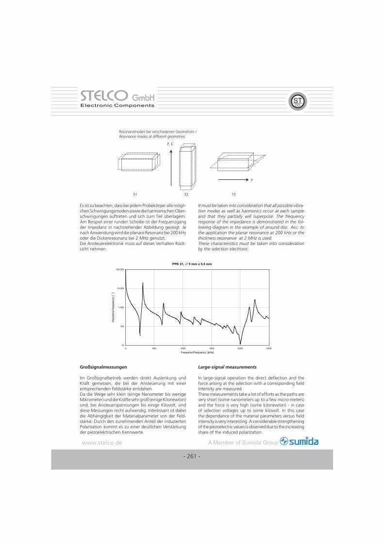
Es ist zu beachten, dass bei jedem Probekörper alle mögli-chen Schwingungsmoden sowie die harmonischen Ober-schwingungen auftreten und sich zum Teil überlagern. Am Beispiel einer runden Scheibe ist der Frequenzgang der Impedanz in nachstehender Abbildung gezeigt. Je nach Anwendung wird die planare Resonanz bei 200 kHz oder die Dickenresonanz bei 2 MHz genutzt.Die Ansteuerelektronik muss auf dieses Verhalten Rück-sicht nehmen.
It must be taken into consideration that all possible vibra-tion modes as well as harmonics occur at each sample and that they partially will superpose. The frequency response of the impedance is demonstrated in the fol-lowing diagram in the example of around disc. Acc. to the application the planar resonance at 200 kHz or the thickness resonance at 2 MHz is used. These characteristics must be taken into consideration by the selection electronic.
Großsignalmessungen
Im Großsignalbetrieb werden direkt Auslenkung und Kraft gemessen, die bei der Ansteuerung mit einer entsprechenden Feldstärke entstehen.Da die Wege sehr klein (einige Nanometer bis wenige Mikrometer) und die Kräfte sehr groß (einige Kilonewton) sind, bei Ansteuerspannungen bis einige Kilovolt, sind diese Messungen recht aufwendig. Interessant ist dabei die Abhängigkeit der Materialparameter von der Feld-stärke. Durch den zunehmenden Anteil der induzierten Polarisation kommt es zu einer deutlichen Verstärkung der piezoelektrischen Kennwerte.
Large-signal measurements
In large-signal operation the direct defl ection and the force arising at the selection with a corresponding fi eld intensity are measured. These measurements take a lot of efforts as the paths are very short (some nanometers up to a few micro-meters) and the force is very high (some kilonewton) - in case of selection voltages up to some kilovolt. In this case the dependance of the material parameters versus fi eld intensity is very interesting. A considerable strengthening of the piezoelectric values is observed due to the increasing share of the induced polarization.
PPK 21, ∅ 5 mm x 0,5 mm
10
100
1.000
10.000
100.000
0 500 1000 1500 2000 2500
Frequenz/Frequency [kHz]
Impe
danz
/ Impe
danc
e [
]
- 261 -
STELCOSTELCO GmbHGmbHElectronic Components
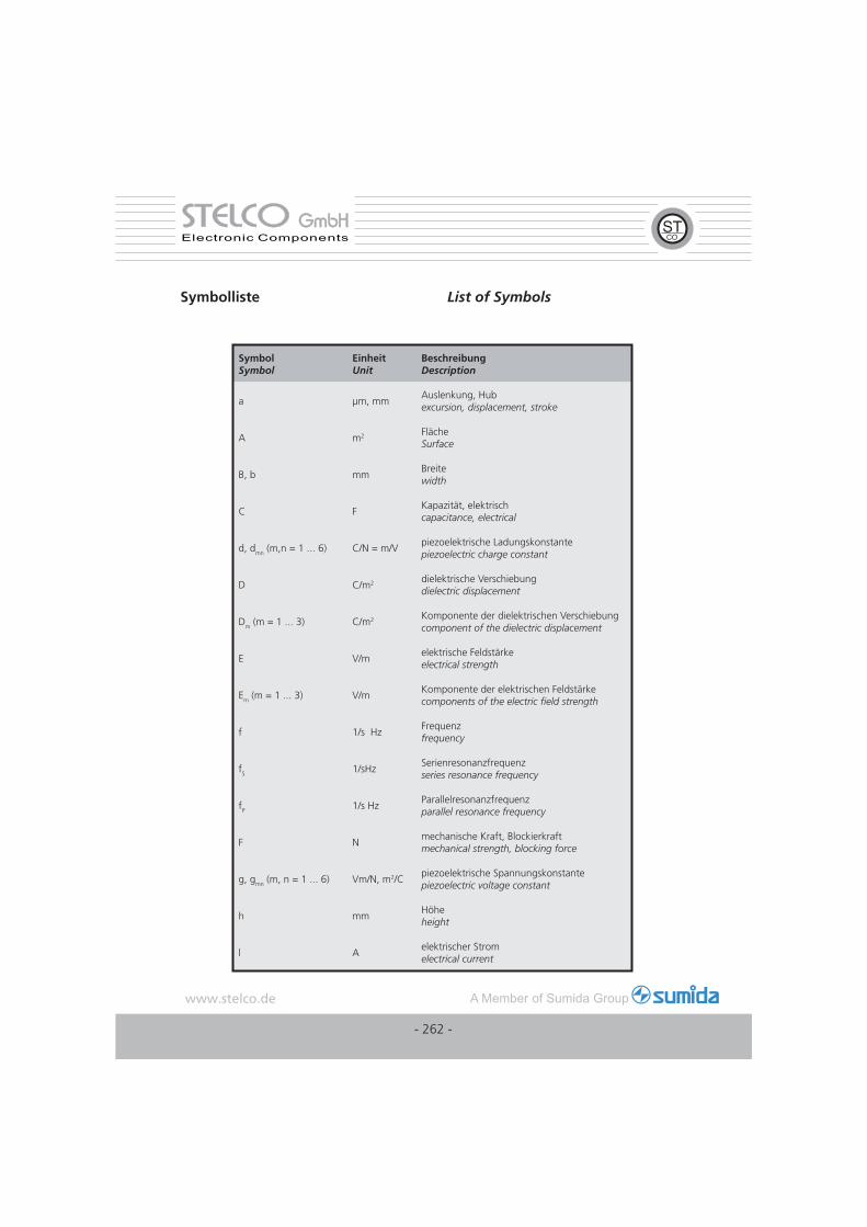
Symbol Symbol
Einheit Unit
Beschreibung Description
a µm, mmAuslenkung, Hub excursion, displacement, stroke
A m2 Fläche Surface
B, b mmBreite width
C FKapazität, elektrisch capacitance, electrical
d, dmn (m,n = 1 ... 6) C/N = m/Vpiezoelektrische Ladungskonstante piezoelectric charge constant
D C/m2 dielektrische Verschiebung dielectric displacement
Dm (m = 1 ... 3) C/m2 Komponente der dielektrischen Verschiebung component of the dielectric displacement
E V/melektrische Feldstärke electrical strength
Em (m = 1 ... 3) V/mKomponente der elektrischen Feldstärke components of the electric fi eld strength
f 1/s HzFrequenz frequency
fS 1/sHzSerienresonanzfrequenz series resonance frequency
fP 1/s HzParallelresonanzfrequenz parallel resonance frequency
F Nmechanische Kraft, Blockierkraft mechanical strength, blocking force
g, gmn (m, n = 1 ... 6) Vm/N, m2/Cpiezoelektrische Spannungskonstante piezoelectric voltage constant
h mmHöhe height
l Aelektrischer Strom electrical current
Symbolliste List of Symbols
- 262 -
STELCOSTELCO GmbHGmbHElectronic Components
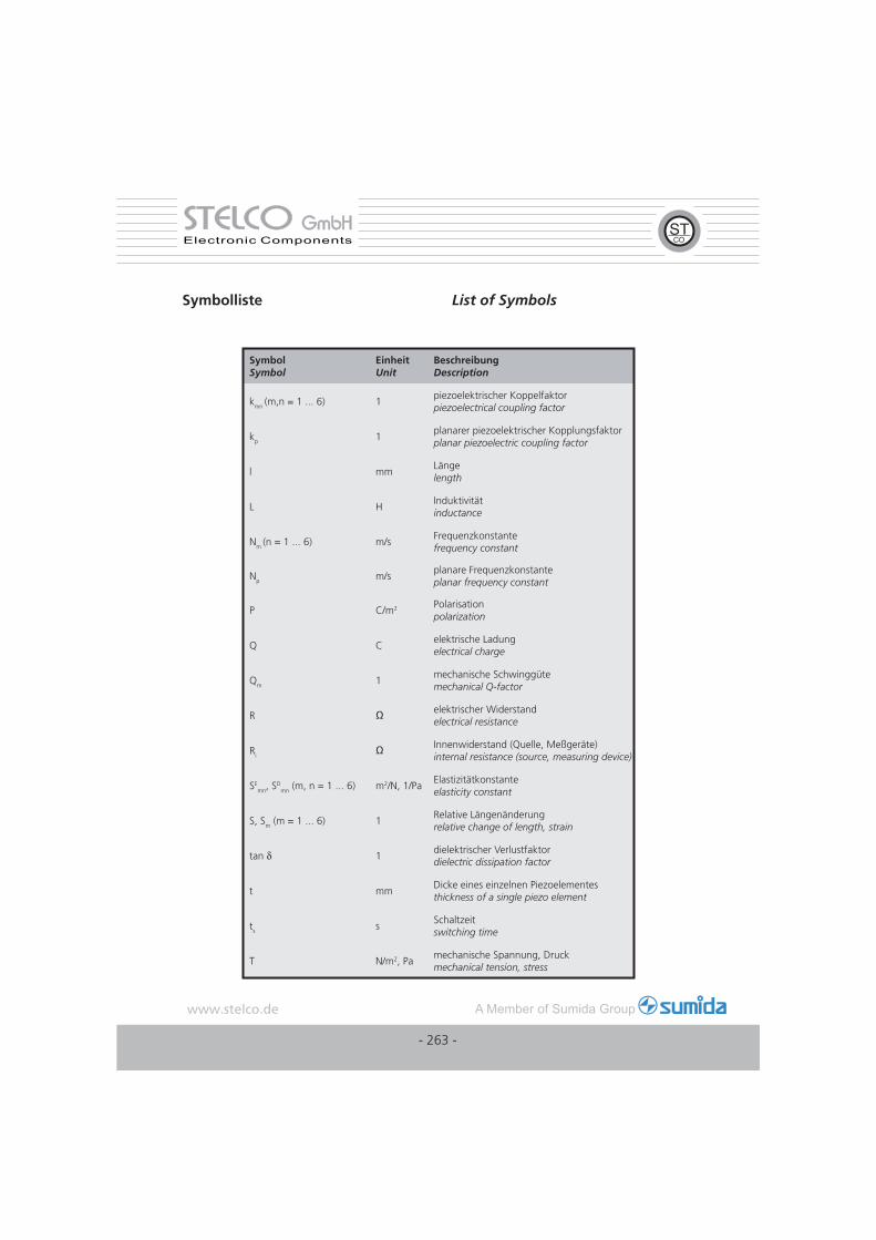
Symbol Symbol
Einheit Unit
Beschreibung Description
kmn (m,n = 1 ... 6) 1piezoelektrischer Koppelfaktor piezoelectrical coupling factor
kp 1planarer piezoelektrischer Kopplungsfaktor planar piezoelectric coupling factor
l mmLänge length
L HInduktivität inductance
Nm (n = 1 ... 6) m/sFrequenzkonstante frequency constant
Np m/splanare Frequenzkonstante planar frequency constant
P C/m2 Polarisation polarization
Q C elektrische Ladung electrical charge
Qm 1mechanische Schwinggüte mechanical Q-factor
R Ω elektrischer Widerstand electrical resistance
RiΩ Innenwiderstand (Quelle, Meßgeräte)
internal resistance (source, measuring device)
SEmn, S
Dmn (m, n = 1 ... 6) m2/N, 1/Pa
Elastizitätkonstante elasticity constant
S, Sm (m = 1 ... 6) 1Relative Längenänderung relative change of length, strain
tan δ 1dielektrischer Verlustfaktor dielectric dissipation factor
t mmDicke eines einzelnen Piezoelementes thickness of a single piezo element
ts sSchaltzeit switching time
T N/m2, Pamechanische Spannung, Druck mechanical tension, stress
Symbolliste List of Symbols
- 263 -
STELCOSTELCO GmbHGmbHElectronic Components
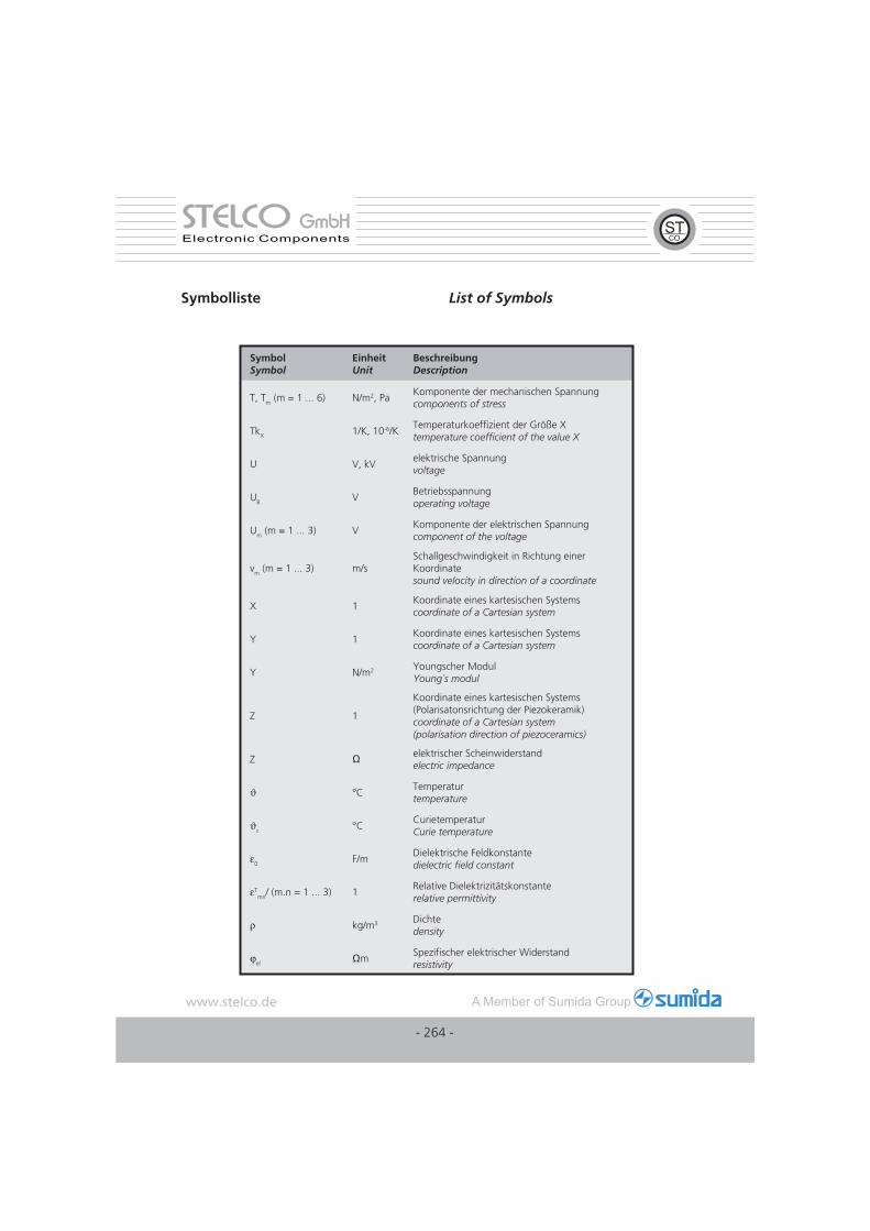
Symbol Symbol
Einheit Unit
Beschreibung Description
T, Tm (m = 1 ... 6) N/m2, PaKomponente der mechanischen Spannung components of stress
TkX 1/K, 10-6/KTemperaturkoeffi zient der Größe Xtemperature coeffi cient of the value X
U V, kVelektrische Spannung voltage
UB V Betriebsspannung operating voltage
Um (m = 1 ... 3) VKomponente der elektrischen Spannung component of the voltage
vm (m = 1 ... 3) m/sSchallgeschwindigkeit in Richtung einer Koordinate sound velocity in direction of a coordinate
X 1Koordinate eines kartesischen Systems coordinate of a Cartesian system
Y 1Koordinate eines kartesischen Systems coordinate of a Cartesian system
Y N/m2 Youngscher Modul Young´s modul
Z 1
Koordinate eines kartesischen Systems (Polarisatonsrichtung der Piezokeramik)coordinate of a Cartesian system (polarisation direction of piezoceramics)
Z Ω elektrischer Scheinwiderstand electric impedance
ϑ °CTemperatur temperature
ϑc °CCurietemperaturCurie temperature
ε0 F/mDielektrische Feldkonstante dielectric fi eld constant
εTmn/ (m.n = 1 ... 3) 1
Relative Dielektrizitätskonstanterelative permittivity
ρ kg/m3 Dichte density
ϕel ΩmSpezifi scher elektrischer Widerstand resistivity
Symbolliste List of Symbols
- 264 -
STELCOSTELCO GmbHGmbHElectronic Components
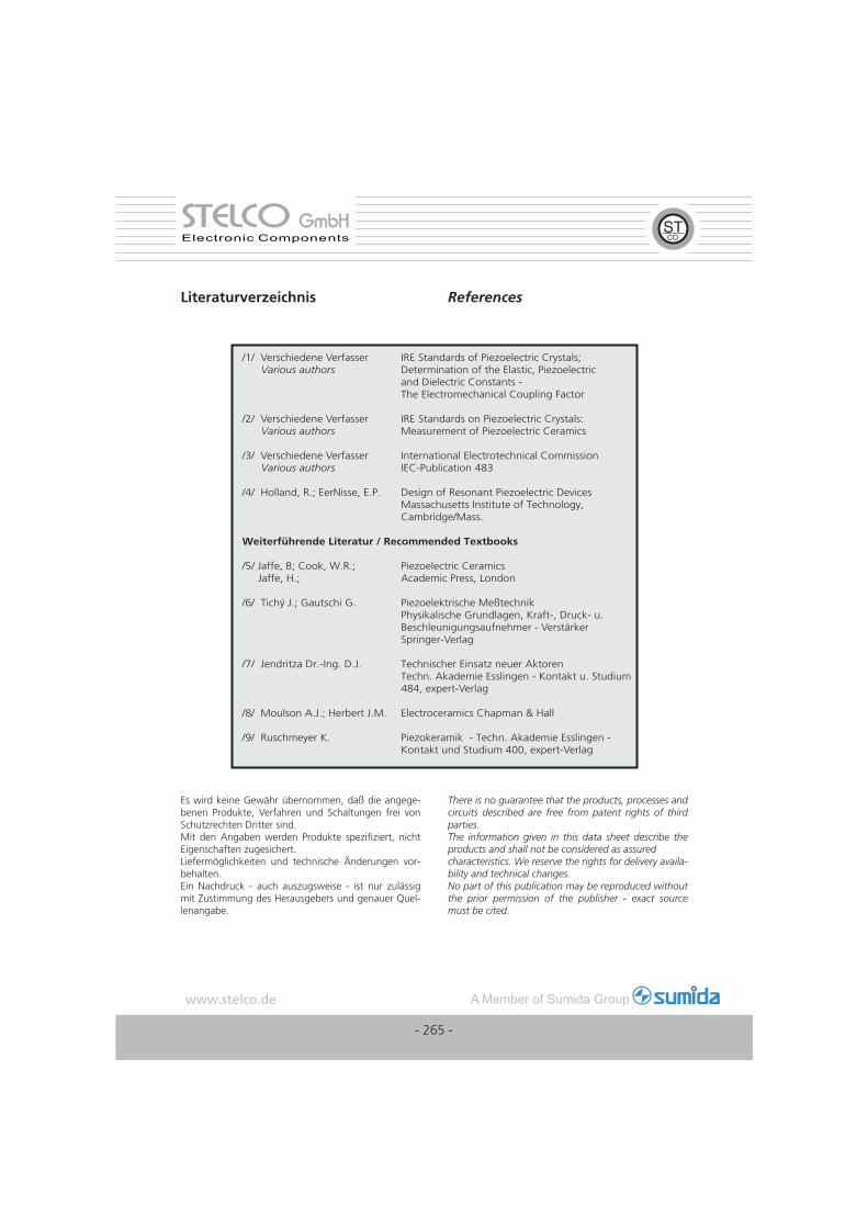
Literaturverzeichnis References
/1/ Verschiedene Verfasser IRE Standards of Piezoelectric Crystals; Various authors Determination of the Elastic, Piezoelectric and Dielectric Constants - The Electromechanical Coupling Factor
/2/ Verschiedene Verfasser IRE Standards on Piezoelectric Crystals: Various authors Measurement of Piezoelectric Ceramics
/3/ Verschiedene Verfasser International Electrotechnical Commission Various authors IEC-Publication 483
/4/ Holland, R.; EerNisse, E.P. Design of Resonant Piezoelectric Devices Massachusetts Institute of Technology, Cambridge/Mass.
Weiterführende Literatur / Recommended Textbooks
/5/ Jaffe, B; Cook, W.R.; Piezoelectric Ceramics Jaffe, H.; Academic Press, London
/6/ Tichý J.; Gautschi G. Piezoelektrische Meßtechnik Physikalische Grundlagen, Kraft-, Druck- u. Beschleunigungsaufnehmer - Verstärker Springer-Verlag
/7/ Jendritza Dr.-Ing. D.J. Technischer Einsatz neuer Aktoren Techn. Akademie Esslingen - Kontakt u. Studium 484, expert-Verlag
/8/ Moulson A.J.; Herbert J.M. Electroceramics Chapman & Hall
/9/ Ruschmeyer K. Piezokeramik - Techn. Akademie Esslingen - Kontakt und Studium 400, expert-Verlag
Es wird keine Gewähr übernommen, daß die angege-benen Produkte, Verfahren und Schaltungen frei von Schutzrechten Dritter sind.Mit den Angaben werden Produkte spezifi ziert, nicht Eigenschaften zugesichert.Liefermöglichkeiten und technische Änderungen vor-behalten.Ein Nachdruck - auch auszugsweise - ist nur zulässig mit Zustimmung des Herausgebers und genauer Quel-lenangabe.
There is no guarantee that the products, processes and circuits described are free from patent rights of third parties.The information given in this data sheet describe the products and shall not be considered as assuredcharacteristics. We reserve the rights for delivery availa-bility and technical changes.No part of this publication may be reproduced without the prior permission of the publisher - exact source must be cited.
- 265 -
STELCOSTELCO GmbHGmbHElectronic Components