Embed Size (px)
Citation preview
1MontagetechnikAssembly technologyTechnique de montageTecnica di montaggioTécnica de montaje
Streckenstütze SZ 1Leg setJambageSupporto trattoMontante de tramo
SZ 1/L SZ 1
2
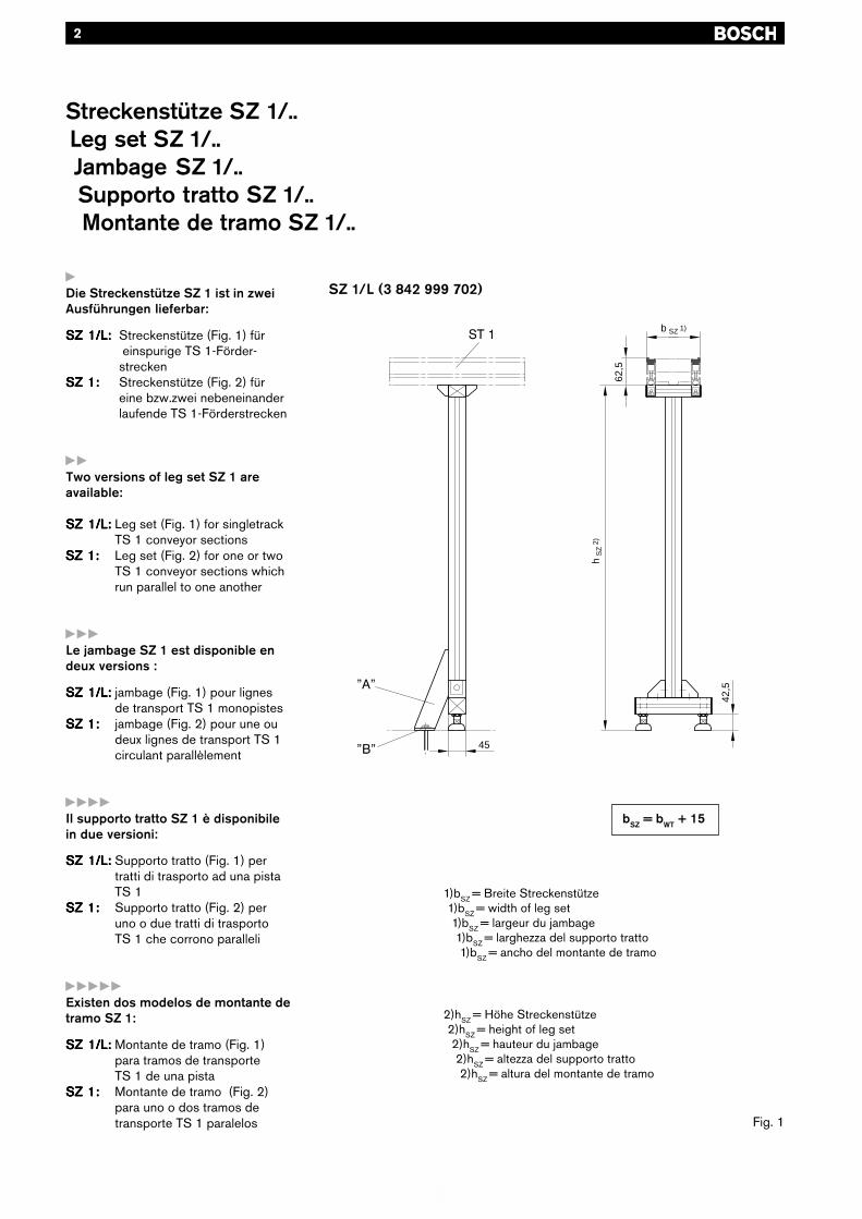
yDie Streckenstütze SZ 1 ist in zweiAusführungen lieferbar:
SZ 1/L:SZ 1/L:SZ 1/L:SZ 1/L:SZ 1/L: Streckenstütze (Fig. 1) für einspurige TS 1-Förder-strecken
SZ 1:SZ 1:SZ 1:SZ 1:SZ 1: Streckenstütze (Fig. 2) füreine bzw.zwei nebeneinanderlaufende TS 1-Förderstrecken
yyTwo versions of leg set SZ 1 areavailable:
SZ 1/L:SZ 1/L:SZ 1/L:SZ 1/L:SZ 1/L: Leg set (Fig. 1) for singletrackTS 1 conveyor sections
SZ 1:SZ 1:SZ 1:SZ 1:SZ 1: Leg set (Fig. 2) for one or twoTS 1 conveyor sections whichrun parallel to one another
yyyLe jambage SZ 1 est disponible endeux versions :
SZ 1/L:SZ 1/L:SZ 1/L:SZ 1/L:SZ 1/L: jambage (Fig. 1) pour lignesde transport TS 1 monopistes
SZ 1:SZ 1:SZ 1:SZ 1:SZ 1: jambage (Fig. 2) pour une oudeux lignes de transport TS 1circulant parallèlement
yyyyIl supporto tratto SZ 1 è disponibilein due versioni:
SZ 1/L:SZ 1/L:SZ 1/L:SZ 1/L:SZ 1/L: Supporto tratto (Fig. 1) pertratti di trasporto ad una pistaTS 1
SZ 1:SZ 1:SZ 1:SZ 1:SZ 1: Supporto tratto (Fig. 2) peruno o due tratti di trasportoTS 1 che corrono paralleli
yyyyyExisten dos modelos de montante detramo SZ 1:
SZ 1/L:SZ 1/L:SZ 1/L:SZ 1/L:SZ 1/L: Montante de tramo (Fig. 1)para tramos de transporteTS 1 de una pista
SZ 1:SZ 1:SZ 1:SZ 1:SZ 1: Montante de tramo (Fig. 2)para uno o dos tramos detransporte TS 1 paralelos
SZ 1/L (3 842 999 702)
1)bSZ = Breite Streckenstütze1)bSZ = width of leg set1)bSZ = largeur du jambage1)bSZ = larghezza del supporto tratto1)bSZ = ancho del montante de tramo
Fig. 1
bSZ = bWT + 15
2)hSZ = Höhe Streckenstütze2)hSZ = height of leg set2)hSZ = hauteur du jambage2)hSZ = altezza del supporto tratto2)hSZ = altura del montante de tramo
Streckenstütze SZ 1/..Leg set SZ 1/..Jambage SZ 1/..Supporto tratto SZ 1/..Montante de tramo SZ 1/..
45
42,5
hS
Z2)
b SZ 1)
62,5
3
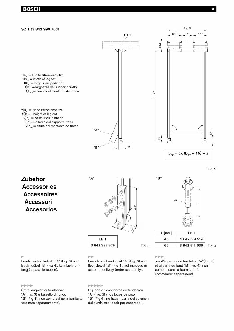
SZ 1 (3 842 999 703)
1)bSZ = Breite Streckenstütze1)bSZ = width of leg set1)bSZ = largeur du jambage1)bSZ = larghezza del supporto tratto1)bSZ = ancho del montante de tramo
“A“ “B“
Fig. 3
Fig. 2
bSZ = 2x (bWT + 15) + a
yFundamentwinkelsatz "A" (Fig. 3) undBodendübel "B" (Fig 4), kein Lieferum-fang (separat bestellen).
yyFoundation bracket kit "A" (Fig. 3) andfloor dowel "B" (Fig 4), not included inscope of delivery (order separately).
yyyJeu d'équerres de fondation "A"(Fig. 3)et cheville de fond "B" (Fig 4), noncompris dans la fourniture (àcommander séparément).
yyyyyEl juego de escuadras de fundación"A" (Fig. 3) y los tacos de piso"B" (Fig 4), no hacen parte del volumendel suministro (pedir por separado).
yyyySet di angolari di fondazione"A"(Fig. 3) e tassello di fondo"B" (Fig 4), non compresi nella fornitura(ordinare separatamente).
Fig. 4
2)hSZ = Höhe Streckenstütze2)hSZ = height of leg set2)hSZ = hauteur du jambage2)hSZ = altezza del supporto tratto2)hSZ = altura del montante de tramo
ZubehörAccessoriesAccessoiresAccessoriAccesorios
b SZ 1)
70
b b +15+15 a
45
42,5
hS
Z2)
62,5
LØ8
L [mm] LE 1
45 3 842 514 919
65 3 842 511 936
LE 1
3 842 338 979
4
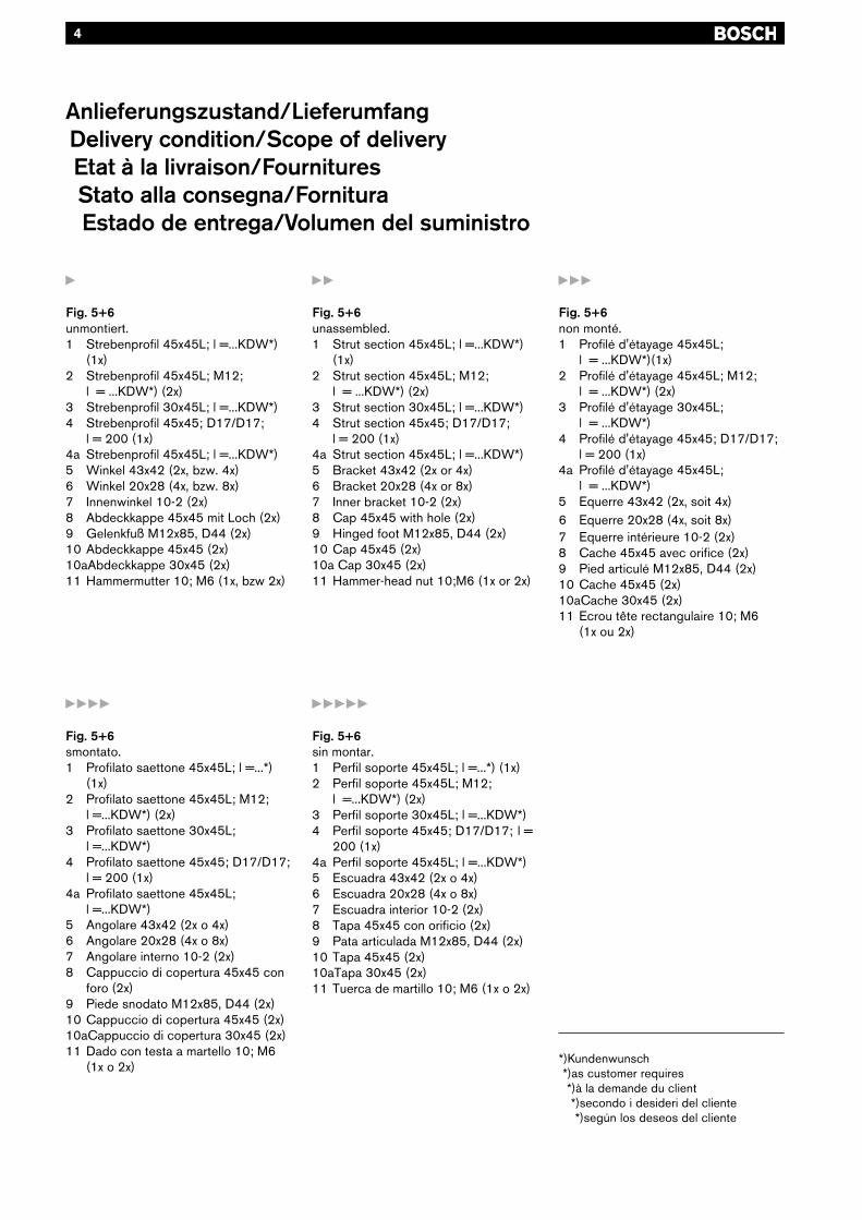
Anlieferungszustand/LieferumfangDelivery condition/Scope of deliveryEtat à la livraison/FournituresStato alla consegna/FornituraEstado de entrega/Volumen del suministro
yyyyy
Fig. 5+6sin montar.1 Perfil soporte 45x45L; l =...*) (1x)2 Perfil soporte 45x45L; M12;
l =...KDW*) (2x)3 Perfil soporte 30x45L; l =...KDW*)4 Perfil soporte 45x45; D17/D17; l =
200 (1x)4a Perfil soporte 45x45L; l =...KDW*)5 Escuadra 43x42 (2x o 4x)6 Escuadra 20x28 (4x o 8x)7 Escuadra interior 10-2 (2x)8 Tapa 45x45 con orificio (2x)9 Pata articulada M12x85, D44 (2x)10 Tapa 45x45 (2x)10aTapa 30x45 (2x)11 Tuerca de martillo 10; M6 (1x o 2x)
yyy
Fig. 5+6non monté.1 Profilé d'étayage 45x45L;
l = ...KDW*)(1x)2 Profilé d'étayage 45x45L; M12;
l = ...KDW*) (2x)3 Profilé d'étayage 30x45L;
l = ...KDW*)4 Profilé d'étayage 45x45; D17/D17;
l = 200 (1x)4a Profilé d'étayage 45x45L;
l = ...KDW*)5 Equerre 43x42 (2x, soit 4x)6 Equerre 20x28 (4x, soit 8x)7 Equerre intérieure 10-2 (2x)8 Cache 45x45 avec orifice (2x)9 Pied articulé M12x85, D44 (2x)10 Cache 45x45 (2x)10aCache 30x45 (2x)11 Ecrou tête rectangulaire 10; M6
(1x ou 2x)
*)Kundenwunsch*)as customer requires*)à la demande du client*)secondo i desideri del cliente*)según los deseos del cliente
y
Fig. 5+6unmontiert.1 Strebenprofil 45x45L; l =...KDW*)
(1x)2 Strebenprofil 45x45L; M12;
l = ...KDW*) (2x)3 Strebenprofil 30x45L; l =...KDW*)4 Strebenprofil 45x45; D17/D17;
l = 200 (1x)4a Strebenprofil 45x45L; l =...KDW*)5 Winkel 43x42 (2x, bzw. 4x)6 Winkel 20x28 (4x, bzw. 8x)7 Innenwinkel 10-2 (2x)8 Abdeckkappe 45x45 mit Loch (2x)9 Gelenkfuß M12x85, D44 (2x)10 Abdeckkappe 45x45 (2x)10aAbdeckkappe 30x45 (2x)11 Hammermutter 10; M6 (1x, bzw 2x)
yy
Fig. 5+6unassembled.1 Strut section 45x45L; l =...KDW*)
(1x)2 Strut section 45x45L; M12;
l = ...KDW*) (2x)3 Strut section 30x45L; l =...KDW*)4 Strut section 45x45; D17/D17;
l = 200 (1x)4a Strut section 45x45L; l =...KDW*)5 Bracket 43x42 (2x or 4x)6 Bracket 20x28 (4x or 8x)7 Inner bracket 10-2 (2x)8 Cap 45x45 with hole (2x)9 Hinged foot M12x85, D44 (2x)10 Cap 45x45 (2x)10a Cap 30x45 (2x)11 Hammer-head nut 10;M6 (1x or 2x)
yyyy
Fig. 5+6smontato.1 Profilato saettone 45x45L; l =...*)
(1x)2 Profilato saettone 45x45L; M12;
l =...KDW*) (2x)3 Profilato saettone 30x45L;
l =...KDW*)4 Profilato saettone 45x45; D17/D17;
l = 200 (1x)4a Profilato saettone 45x45L;
l =...KDW*)5 Angolare 43x42 (2x o 4x)6 Angolare 20x28 (4x o 8x)7 Angolare interno 10-2 (2x)8 Cappuccio di copertura 45x45 con
foro (2x)9 Piede snodato M12x85, D44 (2x)10 Cappuccio di copertura 45x45 (2x)10aCappuccio di copertura 30x45 (2x)11 Dado con testa a martello 10; M6
(1x o 2x)
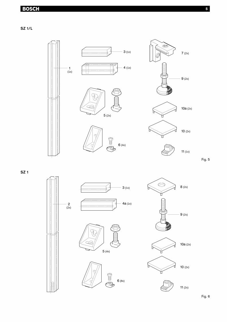
5
SZ 1/L
SZ 1
Fig. 5
Fig. 6
(1x)
(1x)
(1x)
(2x)
(4x)
(2x)
(1x)
(2x)
(2x)
(2x)
(1x)
(1x)
(2x)
(2x)
(2x)
(2x)
(2x)
(4x)
(8x)
(2x)
6
yyy
Un prémontage soigné facilitel'alignement de toute l'installation
Fig. 7:1 Régler préalablement les écrous
hexagonaux M12 (SW19) despieds articulés (9) sur 42,5 mm.
2 Graisser les broches filetées surl'extrémité à insérer jusqu'à 50mmenv.
3 Visser les pieds articulés (9) dans lesmanchons filetés jusqu'à ceque l'écrou hexagonal adhère auprofilé d'étayage (4).
yyyyy
Un premontaje cuidadoso facilita laalineación de toda la instalación
Fig. 7:1 Graduar previamente las tuercas he-
xagonales M12 (SW19) de laspatas articuladas (9) a 42,5 mm.
2 Engrasar el husillo roscado en elextremo a enroscar hasta aprox.50mm.
3 Enroscar las patas articuladas (9) enlos manguitos roscados hastaque la tuerca hexagonal quedejunto al perfil soporte (4).
yyyy
Un premontaggio accurato facilital'allineamento dell'intero impianto
Fig. 7:1 Regolare i dadi esagonali M12
(SW19) dei piedi snodati (9) su42,5mm.
2 Lubrificare circa 50 mmdell'estremità da avvitare dellaspina filettata.
3 Avvitare i piedi snodati (9) nelleboccole filettate finché il dadoesagonale si trovi a paro delprofilato saettone (4).
y
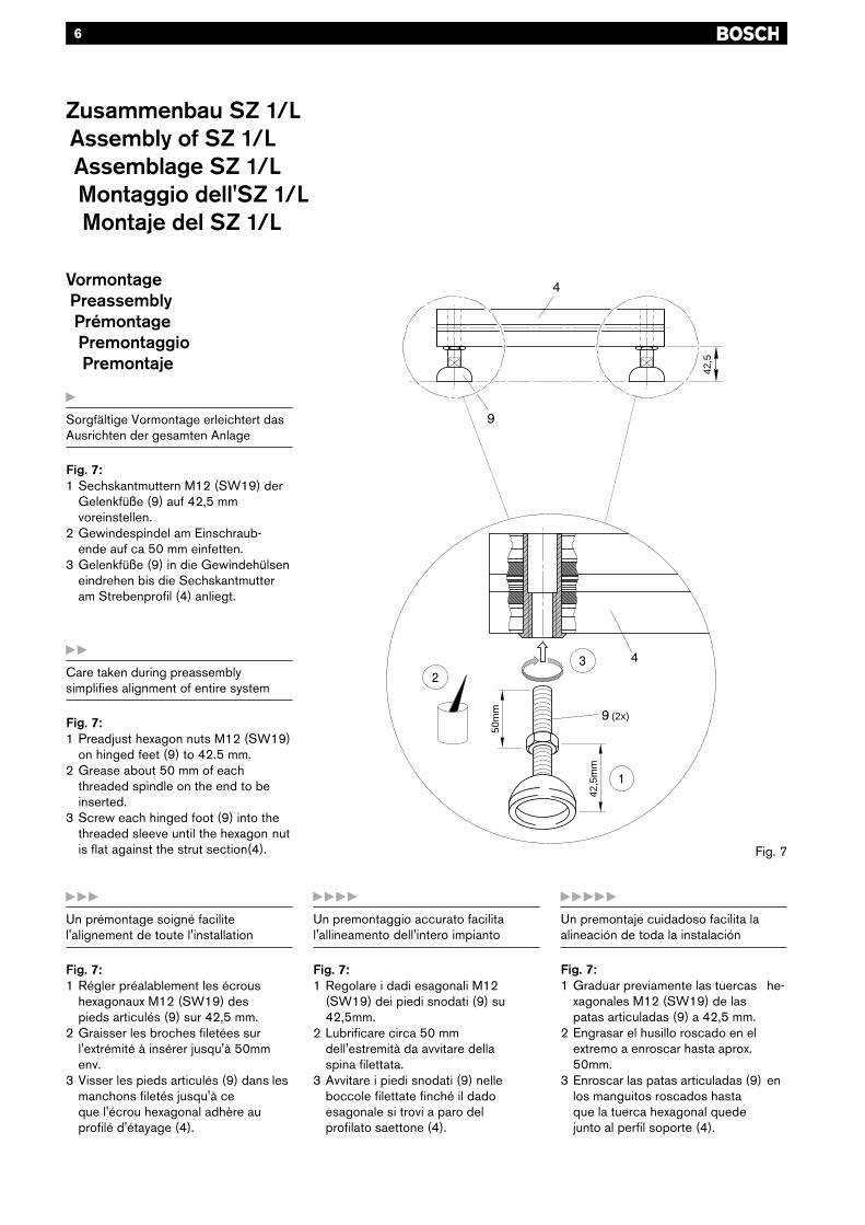
Sorgfältige Vormontage erleichtert dasAusrichten der gesamten Anlage
Fig. 7:1 Sechskantmuttern M12 (SW19) der
Gelenkfüße (9) auf 42,5 mmvoreinstellen.
2 Gewindespindel am Einschraub-ende auf ca 50 mm einfetten.
3 Gelenkfüße (9) in die Gewindehülseneindrehen bis die Sechskantmutteram Strebenprofil (4) anliegt.
yy
Care taken during preassemblysimplifies alignment of entire system
Fig. 7:1 Preadjust hexagon nuts M12 (SW19)
on hinged feet (9) to 42.5 mm.2 Grease about 50 mm of each
threaded spindle on the end to beinserted.
3 Screw each hinged foot (9) into thethreaded sleeve until the hexagon nutis flat against the strut section(4).
Zusammenbau SZ 1/LAssembly of SZ 1/LAssemblage SZ 1/LMontaggio dell'SZ 1/LMontaje del SZ 1/L
VormontagePreassemblyPrémontagePremontaggioPremontaje
Fig. 7
(2x)
50m
m
42,5
mm
42,5
7
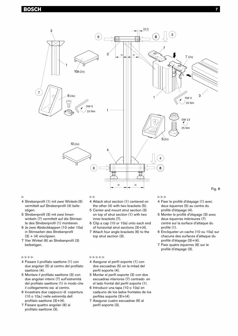
y4 Strebenprofil (1) mit zwei Winkeln (5)
vermittelt auf Strebenprofil (4) befe-stigen.
5 Strebenprofil (3) mit zwei Innen-winkeln (7) vermittelt auf die Stirnsei-te des Strebenprofil (1) montieren.
6 Je zwei Abdeckkappen (10 oder 10a)in Stirnseiten des Strebenprofil(3) + (4) einclipsen.
7 Vier Winkel (6) an Strebenprofil (3)befestigen.
yy4 Attach strut section (1) centered on
the other (4) with two brackets (5).5 Center and mount strut section (3)
on top of strut section (1) with twoinner brackets (7).
6 Clip a cap (10 or 10a) onto each endof horizontal strut sections (3)+(4).
7 Attach four angle brackets (6) to thetop strut section (3).
yyy4 Fixer le profilé d'étayage (1) avec
deux équerres (5) au centre duprofilé d'étayage (4).
5 Monter le profilé d'étayage (3) avecdeux équerres intérieures (7)centré sur la surface d'attaque duprofilé (1).
6 Encliqueter un cache (10 ou 10a) surchacune des surfaces d'attaque duprofilé d'étayage (3)+(4).
7 Fixer quatre équerres (6) sur leprofilé d'étayage (3).
yyyy4 Fissare il profilato saettone (1) con
due angolari (5) al centro del profilatosaettone (4).
5 Montare il profilato saettone (3) condue angolari interni (7) sull'estremitàdel profilato saettone (1) in modo cheil collegamento sia al centro.
6 Incastrare due cappucci di copertura(10 o 10a.) nelle estremità dellprofilato saettone (3)+(4).
7 Fissare quattro angolari (6) alprofilato saettone (3).
yyyyy4 Asegurar el perfil soporte (1) con
dos escuadras (5) en la mitad delperfil soporte (4).
5 Montar el perfil soporte (3) con dosescuadras interiores (7) centrado enel lado frontal del perfil soporte (1).
6 Introducir una tapa (10 o 10a) encadauno de los lados frontales de losperfiles soporte (3)+(4).
7 Asegurar cuatro escuadras (6) alperfil soporte (3).
Fig. 8
==
==
22,5
(2x)
(2x)
10 Nm
SW 5
(4x)
(2x)
SW 13
25 Nm
(2x)
15 Nm
SW 4
8
y
Sorgfältige Vormontage erleichtert dasAusrichten der gesamten Anlage
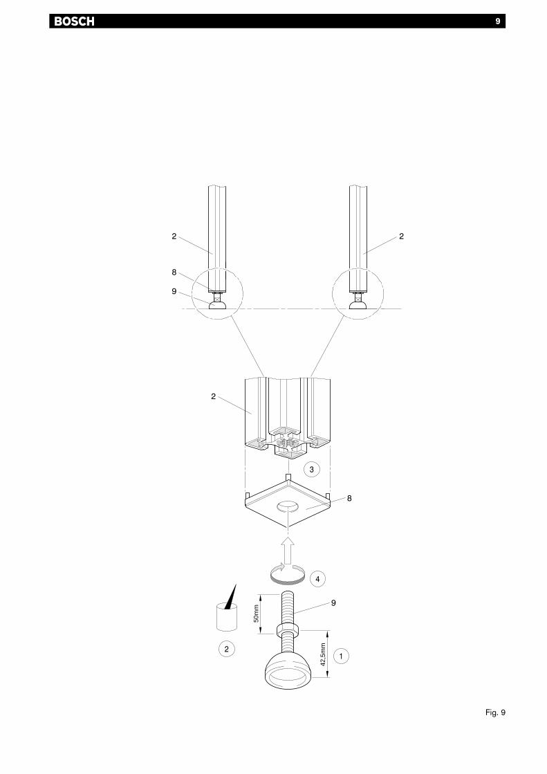
Fig. 9:1 Sechskantmuttern M12 (SW19) der
Gelenkfüße (9) auf 42,5mmvoreinstellen.
2 Gewindespindeln am Einschraub-ende auf ca 50 mm einfetten.
3 Abdeckkappe mit Loch (8) stirnseitigin Strebenprofil (2) einclipsen.
4 Gelenkfüße (9) in die stirnseitigenM12-Gewinde des Strebenprofils (2)eindrehen bis die Sechskantmutter an der Abdeckkappe (8)anliegt.
yyy
Un prémontage soigné facilitel'alignement de toute l'installation
Fig. 9:1 Régler préalablement les écrous
hexagonaux M12 (SW19) despieds articulés (9) à 42,5 mm.
2 Graisser les broches filetées surl'extrémité à insérer jusqu'à 50mmenv.
3 Encliquer le cache avec orifice (8)dans la surface d'attaque du profiléd''étayage (2).
4 Visser les pieds articulés (9) dans lesfilets frontaux M12 du profiléd'étayage (2) jusqu'à ce que l'écrouhexagonal adhère au cache (8).
yyyyy
Un premontaje cuidadoso facilita laalineación de toda la instalación
Fig. 9:1 Graduar previamente las tuercas he-
xagonales M12 (SW19) de laspatas articuladas (9) a 42,5 mm .
2 Engrasar los husillos roscados en elextremo a enroscar hasta aprox. 50mm.
3 Introducir la tapa con perforación (8)en el lado frontal del perfilsoporte (2).
4 Enroscar las patas articuladas (9) enlas roscas frontales M12 del perfilsoporte (2) hasta que la tuerca hexa-gonal quede junto a la tapa (8)
yyyy
Un premontaggio accurato facilital'allineamento dell'intero impianto
Fig. 9:1 Regolare i dadi esagonali M12
(SW19) dei piedi snodati (9) su42,5mm.
2 Lubrificare circa 50 mmdell'estremità da avvitare dellaspina filettata.
3 Incastrare il cappuccio di coperturacon foro (8) sull'estremità del profilatosaettone (2).
4 Avvitare i piedi snodati (9) nellefilettature M12 delle estremità delprofilato saettone (2) finché il dadoesagonale sia a paro del cappuccio dicopertura (8).
yy
Care taken during preassemblysimplifies alignment of entire system
Fig. 9:1 Preadjust hexagon nuts M12(SW19)
on hinged feet (9) to 42.5mm.
2 Grease about 50 mm of eachthreaded spindle on the end to beinserted.
3 Clip the caps with hole (8) onto theends of strut section (2).
4 Screw each hinged foot (9) into theM12 threaded sleeve in the end ofstrut section (2), until the hexagonnutis flat against the cap (8).
Zusammenbau SZ 1Assembly of SZ 1Assemblage SZ 1Montaggio dell'SZ 1Montaje del SZ 1
VormontagePreassemblyPrémontagePremontaggioPremontaje
9
Fig. 9
50m
m
42,5
mm
10
Zusammenbau SZ 1Assembly of SZ 1Assemblage SZ 1Montaggio dell'SZ 1Montaje del SZ 1
y
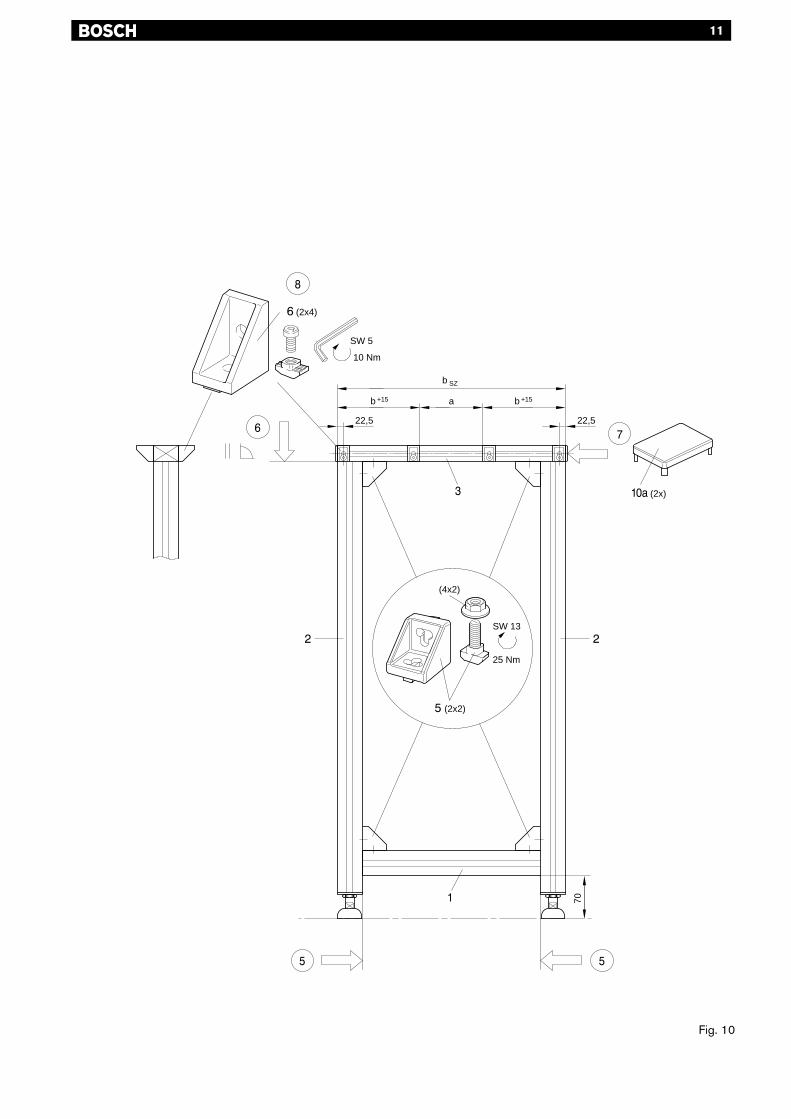
Fig. 10:5 Strebenprofil (1) mit zwei Winkeln (5)
zwischen zwei Strebenprofilen (2) be-festigen (Montagemaß 70 mm!)
6 Strebenprofil (3) mit zwei Winkeln (5)stirnseitig, rechtwinklig und parallelauf den Strebenprofilen(2)befestigen
7 Stirnseiten von Strebenprofil (3) mitAbdeckkappen (10a) verschließen.
8 Acht Winkel (6) an Strebenprofil (3)befestigen, Montagemaße beachten!
yy
Fig. 10:5 Attach strut section (1) between the
two strut sections (2) with two anglebrackets (5) (at a height of 70 mm!)
6 With two angle brackets (5), attachstrut section (3) to the top of,perpendicular to and flush withstrut sections (2).
7 Cover ends of strut section (3) withcaps (10a).
8 Attach eight angle brackets (6) tostrut section (3), noting themounting dimensions!
yyy
Fig. 10:5 Fixer le profilé d'étayage (1) avec
deux équerres (5) entre deux profilés d'étayage (2) (cotes demontage 70 mm!)
6 Fixer le profilé d'étayage (3) avecdeux équerres (5) sur le côtéfrontal des profiles (2), en angledroit et parallèlement.
7 Obturer les surfaces d'attaque duprofilé d'étayage (3) avec descaches (10a).
8 Fixer huits équerres (6) au profiléd'étayage (3), respecter les cotes demontage!
yyyy
Fig. 10:5 Fissare il profilato saettone (1) con
due angolari (5) fra i due profilatisaettone (2) (misura di montaggio70mm!).
6 Montare il profilato saettone (3) condue angolari (5) all'estremità deiprofilati saettone (2), ad angoloretto e parallelamente.
7 Chiudere le estremità del profilato(10a) con cappucci di copertura.
8 Fissare otto angolari (6) al profilatosaettone (3), badando alle misure dimontaggio!
yyyyy
Fig. 10:5 Asegurar el perfil soporte (1) con dos
escuadras (5) entre dos perfilessoporte (2) (medida de montaje 70mm!)
6 Asegurar el perfil soporte (3) condos escuadras (5) en el ladofrontal de los perfiles soporte (2), enángulo recto y paralelo.
7 Tapar los extremos frontales delperfil soporte (3) con tapas (10a) .
8 Asegurar ocho escuadras (6) en elperfil soporte (3). Tener en cuenta lasmedidas de montaje!
11
Fig. 10
22,5
(2x4)
(2x2)
SW 13
25 Nm
(4x2)
b SZ
70
b +15 a
(2x)
22,5
b +15
10 Nm
SW 5
12
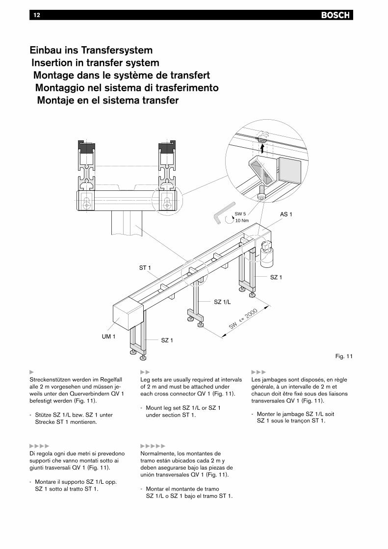
yStreckenstützen werden im Regelfallalle 2 m vorgesehen und müssen je-weils unter den Querverbindern QV 1befestigt werden (Fig. 11).
- Stütze SZ 1/L bzw. SZ 1 unterStrecke ST 1 montieren.
Fig. 11
Einbau ins TransfersystemInsertion in transfer systemMontage dans le système de transfertMontaggio nel sistema di trasferimentoMontaje en el sistema transfer
yyyLes jambages sont disposés, en règlegénérale, à un intervalle de 2 m etchacun doit être fixé sous des liaisonstransversales QV 1 (Fig. 11).
- Monter le jambage SZ 1/L soitSZ 1 sous le trançon ST 1.
yyyyDi regola ogni due metri si prevedonosupporti che vanno montati sotto aigiunti trasversali QV 1 (Fig. 11).
- Montare il supporto SZ 1/L opp.SZ 1 sotto al tratto ST 1.
yyyyyNormalmente, los montantes detramo están ubicados cada 2 m ydeben asegurarse bajo las piezas deunión transversales QV 1 (Fig. 11).
- Montar el montante de tramoSZ 1/L o SZ 1 bajo el tramo ST 1.
yyLeg sets are usually required at intervalsof 2 m and must be attached undereach cross connector QV 1 (Fig. 11).
- Mount leg set SZ 1/L or SZ 1under section ST 1.
10 Nm
SW 5
13
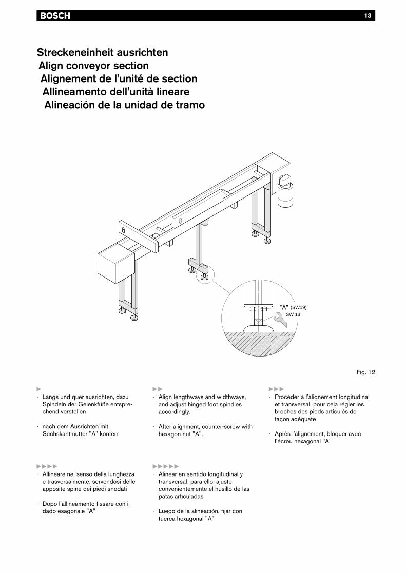
yyy- Procéder à l'alignement longitudinal
et transversal, pour cela régler lesbroches des pieds articulés defaçon adéquate
- Après l'alignement, bloquer avecl'écrou hexagonal "A"
yyyy- Allineare nel senso della lunghezza
e trasversalmente, servendosi delleapposite spine dei piedi snodati
- Dopo l'allineamento fissare con ildado esagonale "A"
yyyyy- Alinear en sentido longitudinal y
transversal; para ello, ajusteconvenientemente el husillo de laspatas articuladas
- Luego de la alineación, fijar contuerca hexagonal "A"
Fig. 12
Streckeneinheit ausrichtenAlign conveyor sectionAlignement de l'unité de sectionAllineamento dell'unità lineareAlineación de la unidad de tramo
y- Längs und quer ausrichten, dazu
Spindeln der Gelenkfüße entspre-chend verstellen
- nach dem Ausrichten mitSechskantmutter "A" kontern
yy- Align lengthways and widthways,
and adjust hinged foot spindlesaccordingly.
- After alignment, counter-screw withhexagon nut "A".
SW 13
(SW19)
14
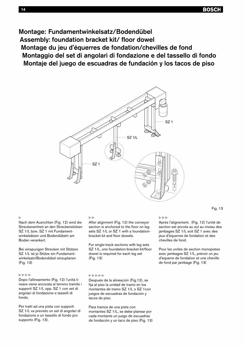
yNach dem Ausrichten (Fig. 12) wird dieStreckeneinheit an den StreckenstützenSZ 1/L bzw. SZ 1 mit Fundament-winkelsätzen und Bodendübeln amBoden verankert.
Bei einspurigen Strecken mit StützenSZ 1/L ist je Stütze ein Fundament-winkelsatz/Bodendübel einzuplanen(Fig. 13)
yyyAprès l'alignement, (Fig. 12) l'unité desection est ancrée au sol au niveau desjambages SZ 1/L soit SZ 1 avec desjeux d'équerres de fondation et deschevilles de fond.
Pour les unités de section monopistesavec jambages SZ 1/L, prévoir un jeud'équerre de fondation et une chevillede fond par jambage (Fig. 13)
yyyyDopo l'allineamento (Fig. 12) l'unità li-neare viene ancorata al terreno tramite isupporti SZ 1/L opp. SZ 1 con set diangolari di fondazione e tasselli difondo.
Per tratti ad una pista con supportiSZ 1/L va previsto un set di angolari difondazione e un tassello di fondo prosupporto (Fig. 13).
yyyyyDespués de la alineación (Fig.12), sefija al piso la unidad de tramo en losmontantes de tramo SZ 1/L o SZ 1conjuegos de escuadras de fundación ytacos de piso.
Para tramos de una pista conmontantes SZ 1/L, se debe planear porcada montante un juego de escuadrasde fundación y un taco de piso (Fig. 13)
Montage: Fundamentwinkelsatz/BodendübelAssembly: foundation bracket kit/ floor dowelMontage du jeu d'équerres de fondation/chevilles de fondMontaggio del set di angolari di fondazione e del tassello di fondoMontaje del juego de escuadras de fundación y los tacos de piso
yyAfter alignment (Fig. 12) the conveyorsection is anchored to the floor on legsets SZ 1/L or SZ 1 with a foundation-bracket kit and floor dowels.
For single-track sections with leg setsSZ 1/L, one foundation-bracket kit/floordowel is required for each leg set(Fig. 13)
Fig. 13
15
Fig. 14
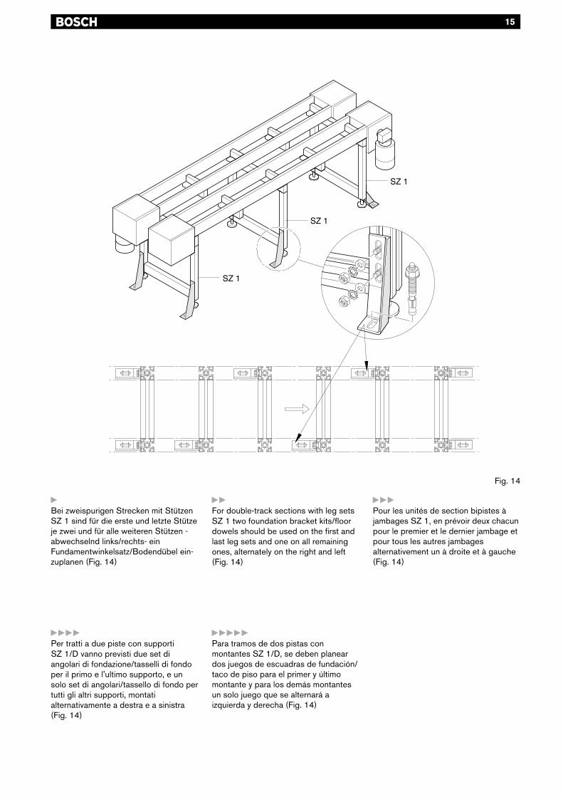
yBei zweispurigen Strecken mit StützenSZ 1 sind für die erste und letzte Stützeje zwei und für alle weiteren Stützen -abwechselnd links/rechts- einFundamentwinkelsatz/Bodendübel ein-zuplanen (Fig. 14)
yyFor double-track sections with leg setsSZ 1 two foundation bracket kits/floordowels should be used on the first andlast leg sets and one on all remainingones, alternately on the right and left(Fig. 14)
yyyPour les unités de section bipistes àjambages SZ 1, en prévoir deux chacunpour le premier et le dernier jambage etpour tous les autres jambagesalternativement un à droite et à gauche(Fig. 14)
yyyyPer tratti a due piste con supportiSZ 1/D vanno previsti due set diangolari di fondazione/tasselli di fondoper il primo e l'ultimo supporto, e unsolo set di angolari/tassello di fondo pertutti gli altri supporti, montatialternativamente a destra e a sinistra(Fig. 14)
yyyyyPara tramos de dos pistas conmontantes SZ 1/D, se deben planeardos juegos de escuadras de fundación/taco de piso para el primer y últimomontante y para los demás montantesun solo juego que se alternará aizquierda y derecha (Fig. 14)

Application Notes:
16
Module WarrantyBOSCH REXROTH CORPORATION warrants to the original purchaser the modules manufactured by us tobe free from defects in materials and workmanship under normal use and service. Our obligation under thiswarranty shall be limited to the repair or exchange of any part or parts which may thus prove defective undernormal use and service within one (1) year from date of installation by the original purchaser. THIS WARRANTYIS EXPRESSLY IN LIEU OF ALL OTHER WARRANTIES EXPRESSED OR IMPLIED, INCLUDING THEWARRANTY OF MERCHANTABILITY OR FITNESS FOR USE, AND WE NEITHER MAKE NOR AUTHORIZEANY OTHER PERSON TO MAKE FOR US, ANY WARRANTY IN CONNECTION WITH THE SALE.
This warranty shall not apply to the modules or any part thereof that has been subject to accident, negligence,alteration, disassembly, abuse, or misuse after delivery by us. The term “Original Purchaser”, as used in thiswarranty, shall be deemed to mean the customer to whom the modules were originally sold.
Our obligation under this warranty is limited to the modules only, and excludes wear items, such as belts, etc.,and we may not be responsible for system concept, design, engineering, or function beyond this.
For further information, contact:
BOSCH REXROTH CORPORATION816 East Third StreetBuchanan, MI 49107Tel: 269-695-0151Fax: 269-695-5363
Liability:In no event can the manufacturer accept warrantyclaims or liability claims for damages resulting fromimproper use of the equipment or as a result ofchanges made to the equipment other than thosespecified in this instruction manual.The manufacturer will accept no claims in which non-original spare parts have been used. For informationon spare parts and replacement parts please callBosch Rexroth Corporation.
Environmental Protection:Always dispose of worn, damaged or obsolete partsin a responsible manner. Some components, such asgearboxes, contain lubricating oil which can pollutethe environment. It is the user’s responsibility todispose of all hazardous material within the compo-nents following all local, state and federal guidelines.Please contact Bosch for copies of the MaterialSafety Data Sheets (MSDS) for the lubricating oilused in gearboxes.
17

Publication No.:3842 521 830 3/00
All rights are held by BOSCH REXROTH CORPORATION and ROBERT BOSCHGMBH, also regarding patent claims. We retain all powers of disposition, such as forcopying and/or for passing-on to third parties.We reserve the right to make technical changes at any time without notice.Errors and omissions excepted.
© 2003 Bosch Rexroth Corporation
BOSCH REXROTH CORPORATION816 E. Third StreetBuchanan, MI 49107TEL: (269) 695-0151FAX: (269) 695-5363www.boschrexroth-us.com
Reprinted in U.S.A.