Embed Size (px)
Citation preview

����������������������������������������Triax Adapter for LDK 100 Series
Technical Manual
3922 496 46791 St.03
Front
RearEng.
Off
Prod.
Viewfinder
Ex1
Mix
Loc
Call
CVBS (Option)
Mic
DC in
Ext
Rear 48V

Für diese Unterlage behalten wir uns alle Rechte vor (Gemäß DIN 34). Technische Änderungen im Zuge der Weiterentwicklung vorbehalten.
Copyright
FCC Class A Statement
Declaration of Conformity
Copying of this document and giving it to others, and the use or com-munication of the contents thereof, are forbidden without express au-thority. Offenders are liable to the payment of damages. All rights are reserved in the event of the grant of a patent or the registration of a utility model or design. Liable to technical alterations in the course of further development.
Toute communication ou reproduc-tion de ce document, toute ex-ploitation ou communication de son contenu sont interdites, sauf au-torisation expresse. Tout man-quement à cette règle est illicite et expose son auteur au versement de dommages et intérêts. Tous nos droits sont réservés pour le cas de la délivrance d'un modèle d'utilité. Sous réserve de modification au cours de l'évolution technique.
© Thomson Multimedia Broadcast Solutions 2002
We, Thomson Broadcast Solutions Nederland B.V., Kapittelweg 10, 4827 HG Breda, The Netherlands declare under our sole responsibility that this product is in compliance with the following standards: EN60065 EN55103-1 EN55103-2following the provisions of: a. the Safety Directives 73/23//EEC and 93/68/EEC b. the EMC Directives 89/336/EEC and 93/68/EEC
: Safety: EMC (Emission): EMC (Immunity)
This product generates, uses, and can radiate radio frequency energy and if not installed and used in accordance with the instructions, may cause interference to radio communications.It has been tested and found to comply with the limits for a class A computing device pursuant to Subpart J of part 15 of FCC rules, which are designed to provide reasonable protection against such interference when operated in a com- mercial environment.Operation of this product in a residential area is likely to cause interference in which case the user at his own expense will be required to take whatever measures may be required to correct the interference.

02.36.2 Technical Manual LDK 5400 - Triax Adapter for LDK 100 Series i
LDK 5400Triax Adapter
Technical Manual
Contents
About This Manual ................................................ ii
Safety Instructions ........................................... 1-1Safety Summary ................................................ 1-2Cautions and Warnings ...................................... 1-2Earthing ............................................................. 1-3
Installation ........................................................ 2-1Packing/Unpacking ............................................ 2-2Attaching an Camera ......................................... 2-3Detaching an Camera ......................................... 2-3Hardware Customization .................................... 2-4Connectors and Cables ...................................... 2-5Specifications .................................................... 2-9
Replacements ................................................... 3-1Introduction ........................................................ 3-2Printed circuit boards ......................................... 3-2
Adjustments ..................................................... 4-1Introduction ........................................................ 4-2Test Equipment ................................................. 4-3Set-up Instructions ............................................. 4-3White Pulse Gain ............................................... 4-5Encoder Board PAL ........................................... 4-7Encoder Board NTSC ....................................... 4-13
Wiring Diagrams .............................................. 5-1Wiring Diagram Triax adapter ............................. 5-2Wiring Diagram Motherboard Triax ..................... 5-5
Mechanical Exploded Views ........................... 6-1Triax Adapter ..................................................... 6-2Triax Adapter Basic ........................................... 6-3
Parts Lists ........................................................ 7-1

ii Technical Manual LDK 5400 - Triax Adapter for LDK 100 Series 02.36.2
About This Manual
Service policyThe LDK 5400 is a sophisticated triax adaptorcontaining state-of-the-art electronic components whichare designed to provide long-life operation without theneed for maintenance. With this in mind, the servicepolicy of Thomson Multimedia Broadcast Solutionsendeavours to ensure that help will be quickly on handin the unlikely event of anything going wrong. Theguiding principles of the Thomson Multimedia BroadcastSolutions first line maintenance philosophy are speedand cost effectiveness. First line maintenance isdedicated to keeping your camera operational, despitea fault, by module replacement and the replacement ofminor mechanical parts by the user.
Purpose of this manualThe provision of correct information is the first step inensuring the operational integrity of the camera.Information on the operation of the camera is to befound in the Operators’s Manual.
This technical manual is an integral part of the servicepolicy. It ensures that you will be able to install and set-up your camera to meet the requirements of yourenvironment. This information on the installation of thetriax adaptor is contained in Section 1 of the manual.The remaining sections of the manual provide first lineservice information so that suitably qualified servicepersonnel can detect and repair faults, normally bymodule replacement.
Because of the complexity of some of the components,second line service can only be carried out at thespecially equipped service centres and informationconcerning second line maintenance is not suppliedin this manual.
Intended audienceThe manual is intended as a guide to those with aworking knowledge of camera systems and installationtechniques. The first line detection and repair of faultsrequires a general knowledge of test and measurementtechniques.
Structure of this manualThe manual is divided into 3 sections:
Section 1: Safety Information.Contains important safety information and should beread before carrying out any work on the triax adaptor.
Section 2: Installation.Gives instructions on the integration of the triaxadaptor into the operating environment and thecustomization of certain hardware functions
Section 3: Replacements.Gives information on the replacement of componentsat first line level.
Section 4: Adjustments.Contains the adjustment procedures to be followed toobtain the best performance from the triax adaptor.
Section 5: Wiring DiagramsContains the wiring diagrams of the triax adaptor.
Section 6: Exploded ViewsContains the Exploded Views of the triax adaptor.
Section 7: Mechanical PartslistContains the Mechanical Partslist diagrams of thetriax adaptor.

02.36.2 Technical Manual LDK 5400 - Triax Adapter for LDK 100 Series iii
Identification and StatusTo indicate the status of a drawing, a box with thenumbers 0 to 9 is shown in the bottom-right of thedrawing. The number that is crossed-out is the statusnumber of the drawing. For example, in the illustrationbelow, the status is 1.
A sticker is used on the units themselves to identifythem and to indicate their status. For example, in theillustration below, the top line is the 12-digit numberthat identifies the unit type.
The first four digits of the number on the second linerepresent a date code (year, week); the next four digitsrepresent the serial number for that week.
The number in the grey area indicates the status of theunit. The last two digits represent the number that willbe given to the next status. However, if these twodigits are contained in a box, then this is the currentstatus. For example, in the illustration above, thecurrent status of the unit is 01.
Line 1 3922 407 00000Line 2 123456AA0101Line 3 VR/0123456789
Line 1This is the code number of the printed circuit boardassy. (PCB)
Line 2This is the serial number of the PCB. The first 6 digitsand the 2 letters are for internal use. The last four digitsreperesent the date of the manufacturing: wwyy.Example:123456AA1402 means the PCB is manufactured inweek 14 of the year 2002.
Line 3This is the status of the PCB.The digit after the first slash is the status. If there is nonumber before the slash, it means that the status isless than 10, a 1 before the slash means the statusis between 10 and 19, a 2 before the slash meansbetween 20 and 29 etc.Example:- VR4567891012 means status 4- VR3/78901234 means status 37.
0 1 2 3 45 6 7 8 9
3922 406 8899100121107 00 01
Example of LDK number:LDK 4501/01 means 8926 450 10101LDK 4500/00 means 8926 450 00001
Numbers of printed circuit board assy- 3922 406 xxxxx or 3922 407 xxxxx
Number (screened in PCB layout) of printed circuitboard assy: 3922 411xxxxx. (not a sparepart)

iv Technical Manual LDK 5400 - Triax Adapter for LDK 100 Series 02.36.2

Safety Instructions Technical Manual LDK 5400 - Triax Adapter for LDK 100 Series 1-1
Section 1
Safety Instructions
This section outlines the precautions that must be taken into account when using the LDK 100camera head.
Contents
Safety Summary ........................................................ 1-2Cautions and Warnings ............................................. 1-2
Earthing ..................................................................... 1-3

1-2 Technical Manual LDK 5400 - Triax Adapter for LDK 100 Series Safety Instructions
Safety Summary
This informaton is intended as a guide for trained andqualified personnel who are aware of the dangers involvedin handling potentially hazardous electrical/electronicequipment. It is not intended to contain a complete list ofall safety precautions which should be observed bypersonnel in using this or other electronic equipment.
The installation, maintenance and service of this equipmentinvolves risks both to personnel and equipment and mustbe performed only by qualified personnel exercising duecare.
Personnel engaged in the installation, operation,maintenance or servicing of this equipment are urged tobecome familiar with First Aid theory and practises.
During installation and operation of this equipment, localbuilding safety and fire protection standards must beobserved.
Before connecting the equipment to the power supply ofthe installation, the proper functioning of the protectiveearth lead of the installation needs to be verified.
Whenever it is likely that safe operation is impaired, theapparatus must be made inoperative and secured againstany unintended operation. The appropriate servicingauthority must then be informed. For example, safety islikely to be impaired if the apparatus fails to perform theintended function or shows visible damage.
This product has been designed and tested according toEN60065.
Cautions and Warnings
When performing service, be sure to read and comply withthe warning and caution notices appearing in the manuals.Warnings indicate danger that requires correct proceduresor practices to prevent death or injury to personnel. Cautionsindicate procedures or practices that should be followedto prevent damage or destruction to equipment or property.
WARNING
THE CURRENT AND VOLTAGES PRESENT IN THISEQUIPMENT ARE DANGEROUS. ALL PERSONNEL
MUST AT ALL TIMES FOLLOW THE SAFETYREGULATIONS.
ALWAYS DISCONNECT POWER BEFORE REMOVINGCOVERS OR PANELS.
ALWAYS DISCHARGE HIGH VOLTAGE POINTSBEFORE SERVICING.
NEVER MAKE INTERNAL ADJUSTMENTS, PERFORMMAINTENANCE OR SERVICE WHEN ALONE OR WHEN
FATIGUED.
IN CASE OF AN EMERGENCY ENSURE THAT THEPOWER IS DISCONNECTED.
ANY INTERRUPTION OF THE PROTECTIONCONDUCTOR INSIDE OR OUTSIDE THE APPARATUS,OR DISCONNECTION OF THE PROTECTIVE EARTH
TERMINAL, IS LIKELY TO MAKE THE APPARATUSDANGEROUS. INTENTIONAL INTERRUPTION IS
PROHIBITED.
FOR SAFETY REASONS THE CPU MUST BE MOUNTEDIN A 19-inch RACK WHICH HAS SAFETY COVERS
ACCORDING TO IEC65.
WHEN TWO CPUs ARE MOUNTED ABOVE EACHOTHER THE MINIMUM DISTANCE BETWEEN THEM
MUST BE 50MM OR THE RACK MUST BE FORCE-AIRCOOLED.
USE ONLY FUSES OF THE TYPE AND RATINGSPECIFIED.
CAUTION
To prevent risk of overheating, ventilate the productcorrectly.
Connect the product only to a power source with thespecified voltage rating.
Only connect a Triax cable from the LDK 6 camerafamily to an LDK 6 CPU. Never connect it to any other
base station.
Never connect the Triax cable from a camera to aCPU of a different family; never connect the LDK
family to the TTV family.
Do not allow system ground currents to exceed 1.5Ain the outer shield of the triax cable or 0.2A in other
cable shields.
It is strickly prohibited to short circuit the inner andouter shields of a triax cable used to connect a
camera to a base station.

Safety Instructions Technical Manual LDK 5400 - Triax Adapter for LDK 100 Series 1-3
Symbol Colour Explanation
Red High voltage terminal at which avoltage, with respect to an otherterminal, exists or may beadjusted to 1000V or more.
Yellow/Black Live part.
Yellow/Black This marking indicates that theoperator must refer to anexplanation in the InstructionManual, or that a specificcomponent must be replaced bythe component specified in thedocumentation for safetyreasons.
White/Black Protective earth (ground)terminal.
Cathode ray tubes
Components marked on the circuit diagram are criticalfor safety and include those specified to comply with X-rayemission standards for units using cathode ray tubes andthose specified for compliance with various regulationsregarding spurious radiation emission.
When servicing units that use cathode ray tubes (CRTs),the cathode ray tubes themselves, the high voltage circuitsand related circuits are specifically chosen so that theycomply with recognized codes pertaining to X-ray emission.
Consequently, when servicing, replace the cathode raytubes and other parts with specified parts only. Do notattempt to modify these circuits as any unauthorizedmodification can increase the high voltage value andcause X-ray emission from the cathode ray tube.
Handle the cathode ray tube only when wearing shatterproofgoggles and after discharging the high voltage completely.
Earthing
The rear of a CPU has two separate screw terminals forprotective earth (PE) and video earth (VE).
These are normally connected by a metal strap. Theprotective earth terminal is internally connected to theprotective earth conductor of the power cable. If required,the central earth connection wire of the studio can beconnected to terminal PE.
In normal circumstances the connection between theprotective earth and the video earth should not be broken.
The metal strap may be removed only if the studio (or OBvan) is equipped with separate protective and video earthsystems. Under these circumstances the video earthterminal must be connected to the central functional earthpotential (video earth) of the studio. This earth potentialshould have functional protective and noiseless earth(FPE) qualities as stated in the VDE regulation 0800/part2.A low impedance interconnection of both earth conductorsmust be provided at the central studio earthing point.
WARNING
THE UNIT MUST ALWAYS BE CONNECTED TOPROTECTIVE EARTH.
VE
PE
Metalstrap
Mains Lead Wiring for UK UsersThe wires in the mains lead are coloured in accordancewith the following code:
GREEN AND YELLOW - EARTHBLUE - NEUTRALBROWN - LIVE
As the colours of the wires in the mains lead of thisapparatus may not correspond with the coloured markingsidentifying the terminals in your plug proceed as follows:• The wire coloured GREEN AND YELLOW must be
connected to the terminal on the plug marked with theletter E or by the safety earth symbol or colouredGREEN or GREEN AND YELLOW.
• The wire coloured BROWN must be connected to theterminal marked with the letter L or coloured RED.
• The wire coloured BLUE must be connected to theterminal marked with the letter N or coloured BLACK.
Ensure that your equipment is connected correctly - if youare in any doubt consult a qualified electrician.

1-4 Technical Manual LDK 5400 - Triax Adapter for LDK 100 Series Safety Instructions

Installation Technical Manual LDK 5400 - Triax Adapter for LDK 100 Series 2-1
Section 2
Installation
This section provides information which is relevant when the adapter is to be used for the first time.Packing and unpacking instructions together with information on the integration of the adapter intoyour studio system are provided. The procedures for the customization of certain hardware functionsand connector information is also provided.
Contents
Packing/Unpacking ............................................ 2-2Attaching an Camera ......................................... 2-3Detaching an Camera ......................................... 2-3
Hardware Customization .................................... 2-4Connectors and Cables ...................................... 2-5Specifications .................................................... 2-9

2-2 Technical Manual LDK 5400 - Triax Adapter for LDK 100 Series Installation
Packing/Unpacking
Inspect the shipping container for evidence of damageimmediately after receipt. If the shipping container orcushioning material is damaged, it should be kept untilthe contents of the shipment have been checked forcompleteness and the units have been checkedmechanically and electrically.The shipping container should be placed upright andopened from the top. Remove the cushioning materialand lift out the contents.The contents of the shipment should be checkedagainst the packing list. If the contents are incomplete,if there is mechanical damage or defect, or if the unitsdo not perform correctly when unpacked, notify yourThomson Multimedia Broadcast Solutions sales orservice centre within eight days. If the shippingcontainer shows signs of damage or stress, notify thecarrier as well.
If a unit is being returned to Thomson MultimediaBroadcast Solutions for servicing, try to use thecontainers and materials of the original packaging.Attach a tag indicating the type of service required,return address, model number, full serial number andthe return number which will be supplied by yourThomson Multimedia Broadcast Solutions servicecentre.
If the original packing can no longer be used, thefollowing general instructions should be used forrepacking with commercially available materials:a. Wrap unit in heavy paper or plastic.b. Use strong shipping container.c. Use a layer of shock-absorbing material around all
sides of the unit to provide firm cushioning andprevent movement inside container.
d. Seal shipping container securely.e. Mark shipping container FRAGILE to ensure careful
handling.

Installation Technical Manual LDK 5400 - Triax Adapter for LDK 100 Series 2-3
Attaching an Camera
The LDK 5400 Adapter is a unit that can be used withthe LDK 100 Camera head. To attach an adapter to thecamera head proceed as follow:
CautionBe extremely careful with the connectors betweenthe camera head and the adapter. Do not allow the
guide pins to damage the pins of the connector.
CautionFollow these steps in the order given. Tightening
the screws in the wrong order could result inmechanical damage to the camera.
a. Using the rail 1 on the bottom of the camera headas a guide, fit the guide pins 2 on either side of theconnector and the guide pin 3 at the top rear of thecamera head into the corresponding slots of theadapter.
b. First, tighten the two horizontal screws 4 on thetop of camera.
c. Next, tighten the two horizontal screws 5 at thefront of the camera.
d. Lastly, tighten the vertical screw 6 in the handle ofthe camera.
Detaching an Camera
To detach an adapter from the camera head follow thesteps for attaching it in the reverse order.
CautionLoosening the screws in the wrong order couldresult in mechanical damage to the camera.
NoteThe procedure is given for the TRiax adapter LDK5400. Follow the same procedure for other adapters.
1
2
3
4
5
6

2-4 Technical Manual LDK 5400 - Triax Adapter for LDK 100 Series Installation
The camera is delivered in a ready-to-use state,however, there are occasions when it might benecessary to re-adjust some functions after, forexample, fitting a new board.A large number of functions can be set-up using thecontrol facilities of the menu system. In addition to thissoftware set-up there are some functions which can beselected or adjusted internally in the camera.Refer to the next chapters for instructions.
Location of boardsUnsrew the five screws on the left side panel and swingdown the cover.
Hardware Customization
1 Data board
2 Encoder board (Option)*
3 Video Mux Ext-Rec board
4 Audio/Intercom TX-Rec board
5 Audio/Intercom LF board
6 Power board
7 Triax backpanel
* LDK 5405/00 Encoder PALLDK 5405/50 Encoder NTSC
1 2 3 4 5 6 7

Installation Technical Manual LDK 5400 - Triax Adapter for LDK 100 Series 2-5
1
32
2
3
1
Connectors and Cables
Triax connector
Fischer1. Inner pin: Signals + power2. Inner shield: Return3. Outer shield: Camera housing
Trilock1. Inner pin: Signals + power2. Inner shield: Return3. Outer shield: Camera housing
ARD1. Inner pin: Signals + power2. Inner shield: Return3. Outer shield: Camera housingpart number 3922 040 01492
LEMO/ LEMO BBC/ LEMO3T1. Inner pin: Signals + power2. Inner shield: Return3. Outer shield: Camera housing
3-pin; panel viewCable part: see page 2-7
1. +12V (Maximum Dissipation 3W)2. Power Return3. Shield
Script light connector
Fischer 3-pin female; panel viewCable part: 2432 026 00274
Power input connector
XLR4-pin male; panel viewCable part: 5322 267 41043
1. Gnd2. n.c.3. n.c.4. +10,5V.......17V4
3
1
2

2-6 Technical Manual LDK 5400 - Triax Adapter for LDK 100 Series Installation
Tuchel 6-pin female; panel viewCable part: 5322 265 30365
1. Microphone return2. Microphone3. Telephone return4. Telephone left5. Telephone right
• Microphone level -58dBm/-20dBm switchable• Microphone impedance 200 ohm• Telephone level +6dBm nominal• Telephone output impedance <10 ohm
Camera headset connector
1. Telephone left2. Not connected3. Microphone4. Microphone return5. Telephone right6. Telephone return
XLR 5-pin female; panel viewCable part: 2422 026 03393
XLR 3-pin female; panel viewCable part 5322 267 41055
1. Audio Screen2. Audio In3. Audio Return
• Microphone impedance > 200 ohm• Sensitivity remote controlled via base station:
range: -70 to -28 dBmmaximum input = -6 dBm
• Signal at pin 2 of audio input is in phase withsignal at pin 2 of audio output on Base Station
Audio microphone connectors
6
5
43
2
1
1
4
5
3
2
1
2
3
Installation Technical Manual LDK 5400 - Triax Adapter for LDK 100 Series 2-7
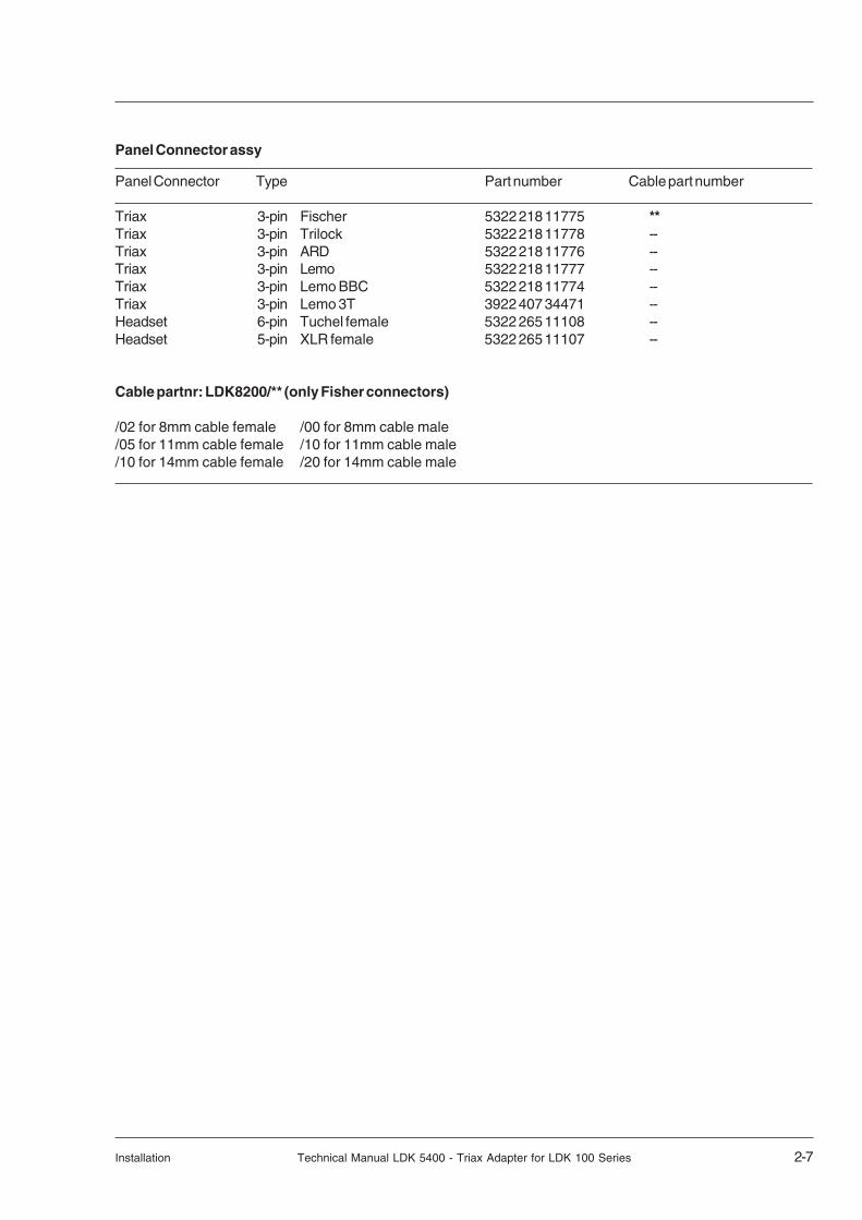
Panel Connector Type Part number Cable part number
Triax 3-pin Fischer 5322 218 11775 **Triax 3-pin Trilock 5322 218 11778 --Triax 3-pin ARD 5322 218 11776 --Triax 3-pin Lemo 5322 218 11777 --Triax 3-pin Lemo BBC 5322 218 11774 --Triax 3-pin Lemo 3T 3922 407 34471 --Headset 6-pin Tuchel female 5322 265 11108 --Headset 5-pin XLR female 5322 265 11107 --
Cable partnr: LDK8200/** (only Fisher connectors)
/02 for 8mm cable female /00 for 8mm cable male/05 for 11mm cable female /10 for 11mm cable male/10 for 14mm cable female /20 for 14mm cable male
Panel Connector assy

2-8 Technical Manual LDK 5400 - Triax Adapter for LDK 100 Series Installation
A row name B row name C row name D row name
1 lon data 1 lon data N 1 GND 1 + batt2 SDA_C 2 SCL_C 2 GND 2 + batt3 INTN_C 3 audio indication 3 GND 3 + batt4 AB batt sense 4 batt sense 4 GND 4 + batt5 adpt id 0 5 adpt id 1 5 GND 5 + batt6 adpt id 2 6 adpt id 3 6 GND 6 + batt7 cam id 0 7 cam id 1 7 GND 7 + batt8 48 kHz 8 PIP 8 GND 8 + batt
9 sync 9 blanking 9 GND 9
10 white pulse 1 10 white pulse 2 10 GND 10
11 colour framing 11 frame reset 11 GND 11
12 BS_TDA 12 H lock 12 GND 12
13 PIP video 13 PIP video ret 13 GND 13
14 BS_TDV 14 BS_TMS 14 GND 14
15 adapter vf video 15 adapter vf video ret 15 GND 15
16 BS_TCK 16 BS_TRSTN 16 GND 16 GND17 ext video 17 ext video ret 17 GND 17 GND18 -5V 18 -5V 18 -5V 18 -5V19 +5V 19 +5V 19 +5V 19 +5V20 +3.3V 20 +3.3V 20 +3.3V 20 +3.3V21 +5VD 21 +5VD 21 +5VD 21 +5VD22 shield 22 shield s 22 GND 22 GND23 mic X 23 mic Xs 23 GND 23 GND
24 mic Y 24 mic Ys 24 GND 24
25 audio level 25 audio level ref 25 GND 25
26 power switch 26 26 GND 26
27 R 27 R ret 27 GND 27
28 YC clock 28 YC clock ret 28 GND 28
29 G 29 G ret 29 GND 29
30 YC9 30 YC9 ret 30 GND 30
31 B 31 B ret 31 GND 31
32 YC8 32 YC8 ret 32 GND 32
33 YC7 33 YC7 ret 33 GND 33
34 YC6 34 YC6 ret 34 GND 34 housing35 YC5 35 YC5 ret 35 GND 35 housing36 YC4 36 YC4 ret 36 GND 36 housing37 YC3 37 YC3 ret 37 n.c. 3738 YC2 38 YC2 ret 38 n.c. 3839 YC1 39 YC1 ret 39 -80V 3940 YC0 40 YC0 ret 40 -80V 40
Docking connector Adapter
ABCD
1 40
160-pin female; panel view

Installation Technical Manual LDK 5400 - Triax Adapter for LDK 100 Series 2-9
Specifications
LDK 100 (with Triax adapter)
General data
Power requirements triax powered or 12V dcPower consumption 20 W (Head + VF)
Operating temperatures-20 to +45°C (-4 to +113°F)
Storage temperatures-20 to +60°C (-4 to +140°F)
Weight (approx.)4.9 kg (14.1 lb) incl. 1.5-inch VF and triax adapter
Triax cable length2,400m (7,875 ft) max. with 16mm (0.63") cable
Camera section
Pick-up device3 x 2/3-inch Philips Frame Transfer Sensors or3 x 2/3-inch switchable DPM Sensors
Picture elementsNTSC: 1000(h) x 498(v)PAL: 1000(h) x 594(v)
Digital quantization12 bits A/d
Digital signal processing18 MHz and 36 MHz, 24 bits accuracy
Sensitivity2000 lux (186 ft cd) at F9.0 reflectance 89.9%
Minimum illuminationApprox. 1 lux at F 1.4 and +36 dB gain
Exposure controlDown to 1/1000
Clean scanningNTSC: between 61.1 and 151.0 HzPAL: between 51.0 and 103.0 Hz
Optical systemF1.4 with quartz filter
Optical filtersClear; 1/4 ND, 1/16 ND, 1/64 ND
Modulation depth>70% at 5Mhz
S/N ratioTypical: 60 dB PAL and 62 dB NTSC
Registration<25 ns (0.05%) in all zones, without lens
Dynamic range>600%
Gain-6dB to +36dB in 3dB steps (user defined presets)
Inputs
Front mic. 1 x XLR 3, balanced, +48VMic. 1 x XLR 3, balanced, +48VDC 12V XLR 4Control input 9-pin, RS232 compatible
Outputs
Triax Option: Fischer/ARD/Lemo/Trilock
Lens 12pViewfinder 20pCameraman headset Option: XLR5/TuchelVideo (CVBS) out Option: 1 Vpp; 75 Ohm; BNCMonitor (Y) 1 Vpp; 75 Ohm; BNCScriptlight power 3p; 12V
Connectors Base Station LDK 4053
Triax Option: Fischer/ARD/Lemo/Trilock
Power AC-power connectorAudio XLR 3Intercom ENG/PROD/PROG
via 15p D-connectorSignalling Call/Tally R/Y via 15p D-conn.CVBS (3x) 1 Vpp; 75 Ohm; BNCRGB 700 mVpp; 75 Ohm; BNCY, R-Y, B-Y 700, 525, 525 mVpp; 75 Ohm;
BNCPXM 1 Vpp; 75 Ohm; BNCWFM 1 Vpp; 75 Ohm; BNCSerial Digital (2x) 270 MB/s Option: 800 mV; 75 Ohm; BNCExt 1 1 Vpp; 75 Ohm; BNCGenlock in 1 Vpp; 75 Ohm; BNCExt. Camera Control 4p DATA
These typical specifications are valid for PAL and NTSCsystems and are subject to change without notice

2-10 Technical Manual LDK 5400 - Triax Adapter for LDK 100 Series Installation

Replacements Technical Manual LDK 5400 - Triax Adapter for LDK 100 Series 3-1
Section
Replacements
This section gives information on the procedures to follow when replacing printed circuit boards andmechanical components at first line level.
Contents
Introduction ........................................................ 3-2 Printed circuit boards ......................................... 3-2
3-2 Technical Manual LDK 5400 - Triax Adapter for LDK 100 Series Replacements
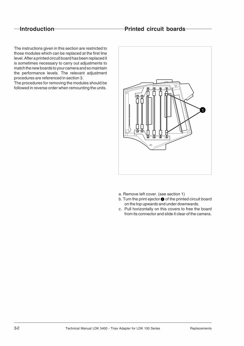
Introduction Printed circuit boards
The instructions given in this section are restricted tothose modules which can be replaced at the first linelevel. After a printed circuit board has been replaced itis sometimes necessary to carry out adjustments tomatch the new boards to your camera and so maintainthe performance levels. The relevant adjustmentprocedures are referenced in section 3.The procedures for removing the modules should befollowed in reverse order when remounting the units.
a. Remove left cover. (see section 1)b. Turn the print ejector 1 of the printed circuit board
on the top upwards and under downwards.c. Pull horizontally on this covers to free the board
from its connector and slide it clear of the camera.
1
Adjustments Technical Manual LDK 5400 - Triax Adapter for LDK 100 Series 4-1
Section 4
Adjustments
This section contains the adjustment procedures to be followed to obtain the best performance fromthe camera. These procedures need only be used if, following a module replacement, the cameradoes not perform according to specifications.
Contents
Introduction ........................................................ 4-2Test Equipment ................................................. 4-3Set-up Instructions ............................................. 4-3
White Pulse Gain ............................................... 4-5Encoder Board PAL ........................................... 4-7Encoder Board NTSC ....................................... 4-13

4-2 Technical Manual LDK 5400 - Triax Adapter for LDK 100 Series Adjustments
Introduction
This unit is factory tested and adjusted for operationaluse. Under normal circumstances, the internal automaticcalibration procedures do not need to be started and theinternal potentiometers do not need to be adjusted.
The only situation that might require some realignmentof the adapter is when a printed circuit board has beenreplaced.
If the Video Mux. board is replaced, readjust the whitepulse amplitude.
If the Encoder board is replaced, follow the procedurefor its readjustment. The encoder timing adjustmentscan be carried out via the menu system.
If it is discovered that the unit is misaligned, the followingprocedures are given as a guide for competent servicepersonnel, who have a thorough knowledge of thecamera and have the use of calibrated equipment, torealign the unit.
If no improvement can be achieved or an adjustment isout of range, please contact your local supplier or thenearest Thomson Multimedia Broadcast SolutionsService Centre.
The adjustment procedures are designed as separateunits. Within a numbered procedure do not change theposition of switches or jumpers unless instructed to doso in the procedure.
These adjustment procedures are for the Triax Adapter.However, for practical purposes the Triax Adapter isused together with the camera head to facilitate somemeasurements.

Adjustments Technical Manual LDK 5400 - Triax Adapter for LDK 100 Series 4-3
CAUTION:Do not attempt to improve camera performance
by adjusting individual potentiometers, jumpers or switchesas this may lead to complete misalignment of the camera.
CAUTION:Do not realign individual potentiometers, jumpers or switches
not mentioned in this chapter or earlier in this manual.These adjustment points are for factory use only.
CAUTION:Switch off the power supply to the camera
before removing or replacing printed circuit boards.
Set-up Instructions
Before carrying out any adjustments the following stepsare recommended:• Attach the adapter to the camera.• Install the camera on a tripod.• Attach the lens and the necessary cables.• Allow the camera to warm-up.
Test Equipment
The following is a list of equipment required to carry outthe adjustment procedure:• Set of board extenders LDK 5820/01• Oscilloscope (with cursor measurement)• Waveform monitor

4-4 Technical Manual LDK 5400 - Triax Adapter for LDK 100 Series Adjustments
White Pulse Gain
Extender Board
Video Mux. Board
49 50
46 47 48
49 50
46 47 48
44 45
41 42 43
44 45
41 42 43
39 40
36 37 38
34 35
31 32 33
29 30
26 27 28
24 25
21 22 23
19 20
16 17 18
14 15
11 12 13
9 10
6 7 8
4 5
1 2 3
14 15
11 12 13
9 10
6 7 8
4 5
1 2 3
24 25
21 22 23
19 20
16 17 18
34 35
31 32 33
29 30
26 27 28
39 40
36 37 38
50A50B
1A1B
X2
A B
A B
50B50A
1B1A
X1
ZR253
ZR653
ZR449 ZMP400
ZMP600
ZMP200

Adjustments Technical Manual LDK 5400 - Triax Adapter for LDK 100 Series 4-5
White Pulse Gain
White pulse amplitude1. Switch off power. Place Video Mux.board on service extender. Switch on power.2. Connect adapter to a base station and switch on colour bar.3. Adjust the white pulse in line 10 (PAL), in line 13 (NTSC) for the R-Mux output to equal the video level.
Measure at: Adjust with: Required result: Correct:
ZMP200 ZR253 700mV
4. Adjust video level to equal the white pulse in line 10 (PAL), in line 13 (NTSC) for the G-Mux output.
Measure at: Adjust with: Required result: Correct:
ZMP400 ZR449 700mV
5. Adjust the white pulse in line 11 (PAL), in line 14 (NTSC) for the B-Mux output to equal the video level.
Measure at: Adjust with: Required result: Correct:
ZMP600 ZR653 700mV
0%
10
90
100
0%
10
90
100
0%
10
90
100

4-6 Technical Manual LDK 5400 - Triax Adapter for LDK 100 Series Adjustments
Encoder Board PAL
ZL513
ZR529 ZR114 ZR314
ZR717 ZR722ZR528
ZL1111234
ZL311
ZMP100 ZMP300
ZMP108
ZMP308
ZMP502
ZMP500
ZMP105
ZMP106
ZMP107
ZR124 ZR324
ZMP901
ZR902
ZR326ZL105
ZMP902ZMP900
ZMP800
ZMP802ZMP903
ZL801 ZL800
ZMP0
ZMP700
ZMP1
ZS1
R171
R542
R525
Adjustments Technical Manual LDK 5400 - Triax Adapter for LDK 100 Series 4-7
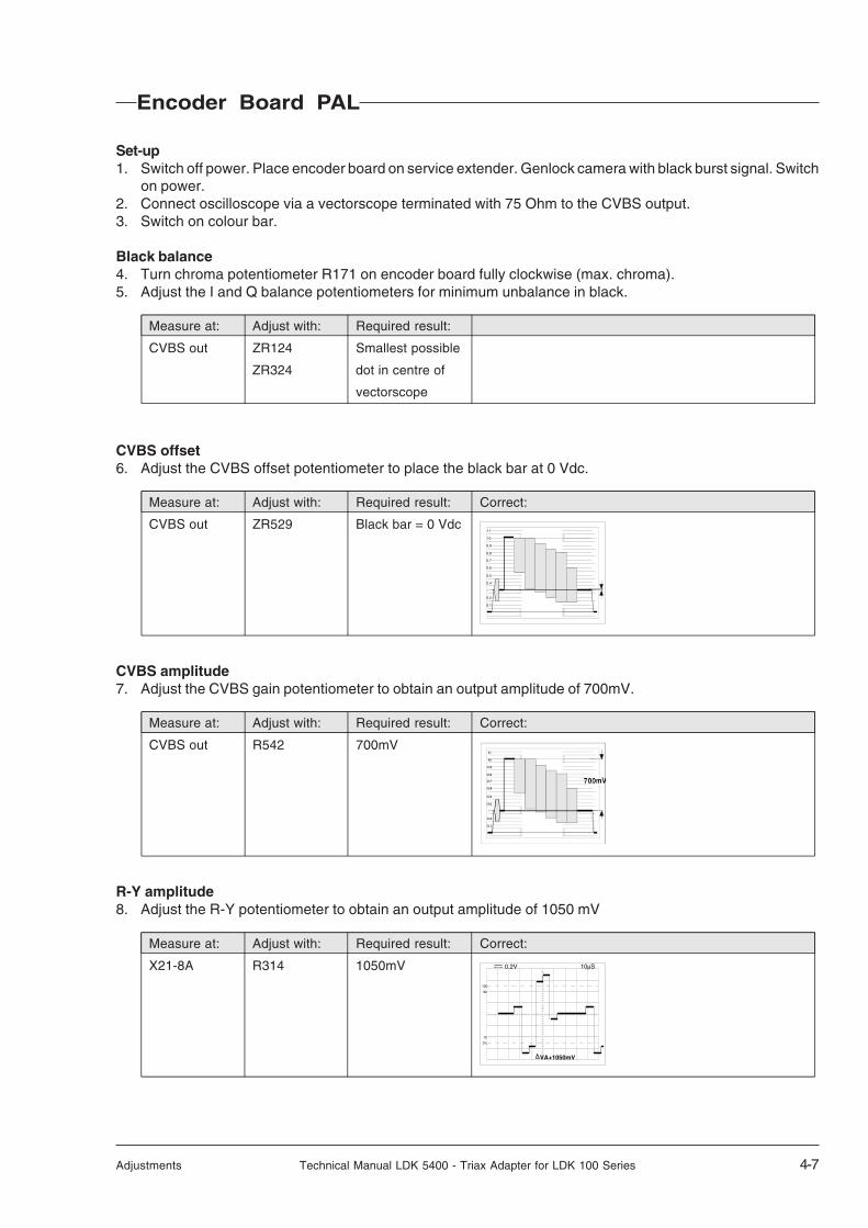
Encoder Board PAL
Set-up1. Switch off power. Place encoder board on service extender. Genlock camera with black burst signal. Switch
on power.2. Connect oscilloscope via a vectorscope terminated with 75 Ohm to the CVBS output.3. Switch on colour bar.
Black balance4. Turn chroma potentiometer R171 on encoder board fully clockwise (max. chroma).5. Adjust the I and Q balance potentiometers for minimum unbalance in black.
Measure at: Adjust with: Required result:
CVBS out ZR124 Smallest possible
ZR324 dot in centre of
vectorscope
CVBS offset6. Adjust the CVBS offset potentiometer to place the black bar at 0 Vdc.
Measure at: Adjust with: Required result: Correct:
CVBS out ZR529 Black bar = 0 Vdc
CVBS amplitude7. Adjust the CVBS gain potentiometer to obtain an output amplitude of 700mV.
Measure at: Adjust with: Required result: Correct:
CVBS out R542 700mV
R-Y amplitude8. Adjust the R-Y potentiometer to obtain an output amplitude of 1050 mV
Measure at: Adjust with: Required result: Correct:
X21-8A R314 1050mV
0.1
0.2
0.4
0.5
0.6
0.7
0.8
0.9
10
11
0%
10
90
100
0.2V 10µS
VA+1050mV

4-8 Technical Manual LDK 5400 - Triax Adapter for LDK 100 Series Adjustments
Encoder Board PAL
ZL513
ZR529 ZR114 ZR314
ZR717 ZR722ZR528
ZL1111234
ZL311
ZMP100 ZMP300
ZMP108
ZMP308
ZMP502
ZMP500
ZMP105
ZMP106
ZMP107
ZR124 ZR324
ZMP901
ZR902
ZR326ZL105
ZMP902ZMP900
ZMP800
ZMP802ZMP903
ZL801 ZL800
ZMP0
ZMP700
ZMP1
ZS1
R171
R542
R525

Adjustments Technical Manual LDK 5400 - Triax Adapter for LDK 100 Series 4-9
B-Y amplitude9. Adjust the B-Y gain potentiometer to obtain an output amplitude of 1050mV.
Measure at: Adjust with: Required result: Correct:
X21-11A ZR114 1050mV
BURST ADJUSTMENTS
Burst phase10. Measure in second quadrant of vectorscope.
Adjust the input sensitivity potentiometer of the vectorscope so the burst vectors just touch the circlegraticule.
11. Adjust the burst phase potentiometer for 90° phase output.
Measure at: Adjust with:
CVBS out ZR722
Burst amplitude12. Adjust the burst amplitude potentiometer to obtain a burst amplitude of 300mV.
Measure at: Adjust with: Required result: Correct:
CVBS out ZR717 300mV
Sc-H phase relationship13. Switch vectorscope to internal synchronisation.14. Adjust Sc-H phase potentiometer for 180°.
Measure at: Adjust with: Required result: Correct:
CVBS out ZR902
Encoder Board PAL
0%
10
90
100
0.2V 10µS
VA+1050mV
0%
10
90
100
0.1V 2µS
VA+300mV
20
40
R
60
80
0.7100
120
20
43 0.3
g
YL
MG
cy
b
Byl
G
r CY
mg
75100
U
V
0
0
5
-5
% VOLT

4-10 Technical Manual LDK 5400 - Triax Adapter for LDK 100 Series Adjustments
Encoder Board PAL
ZL513
ZR529 ZR114 ZR314
ZR717 ZR722ZR528
ZL1111234
ZL311
ZMP100 ZMP300
ZMP108
ZMP308
ZMP502
ZMP500
ZMP105
ZMP106
ZMP107
ZR124 ZR324
ZMP901
ZR902
ZR326ZL105
ZMP902ZMP900
ZMP800
ZMP802ZMP903
ZL801 ZL800
ZMP0
ZMP700
ZMP1
ZS1
R171
R542
R525

Adjustments Technical Manual LDK 5400 - Triax Adapter for LDK 100 Series 4-11
Sync amplitude15. Adjust the sync, amplitude potentiometer fto obtain a sync. ampliatude of 300mV.
Measure at: Adjust with: Required result: Correct:
CVBS out ZR525 300mV
Y offset16. Adjust the Y offset potentiometer to place the black bar at the 0Vdc level.
Measure at: Adjust with: Required result: Correct:
X21-14A ZR52 Black bar = 0 Vdc
Y amplitude17. Adjust the Y gain potentiometer to obtain an output amplitude of 1400mV.
Measure at: Adjust with: Required result: Correct:
X21-14A ZR528 1400mV
18. Switch off power and return encoder board to its position in the camera.
Encoder Board PAL
0%
10
90
100
0.1V 2µS
VA+300mV
0%
10
90
100
0.2V 5µS
VA+1400mV
0%
10
90
100
0.2V 5µS
VA+1400mV

4-12 Technical Manual LDK 5400 - Triax Adapter for LDK 100 Series Adjustments
Encoder Board NTSC
ZL513
ZR529 ZR114 ZR314
ZR717 ZR722ZR528
ZL1111234
ZL311
ZMP100 ZMP300
ZMP108
ZMP308
ZMP502
ZMP500
ZMP105
ZMP106
ZMP107
ZR124 ZR324
ZMP901
ZR902
ZR326ZL105
ZMP902ZMP900
ZMP800
ZMP802ZMP903
ZL801 ZL800
ZMP0
ZMP700
ZMP1
ZS1
R171
R542
R525
Adjustments Technical Manual LDK 5400 - Triax Adapter for LDK 100 Series 4-13
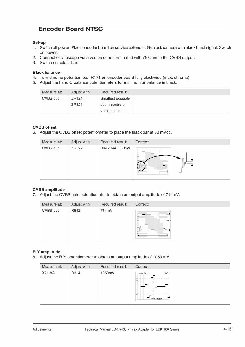
Encoder Board NTSC
Set-up1. Switch off power. Place encoder board on service extender. Genlock camera with black burst signal. Switch
on power.2. Connect oscilloscope via a vectorscope terminated with 75 Ohm to the CVBS output.3. Switch on colour bar.
Black balance4. Turn chroma potentiometer R171 on encoder board fully clockwise (max. chroma).5. Adjust the I and Q balance potentiometers for minimum unbalance in black.
Measure at: Adjust with: Required result:
CVBS out ZR124 Smallest possible
ZR324 dot in centre of
vectorscope
CVBS offset6. Adjust the CVBS offset potentiometer to place the black bar at 50 mVdc.
Measure at: Adjust with: Required result: Correct:
CVBS out ZR529 Black bar = 50mV
CVBS amplitude7. Adjust the CVBS gain potentiometer to obtain an output amplitude of 714mV.
Measure at: Adjust with: Required result: Correct:
CVBS out R542 714mV
R-Y amplitude8. Adjust the R-Y potentiometer to obtain an output amplitude of 1050 mV
Measure at: Adjust with: Required result: Correct:
X21-8A R314 1050mV
0%
10
90
100
0.2V 10µS
VA+1050mV
0.1
0.2
0.4
0.5
0.6
0.7
0.8
0.9
10
11
0.1
0.2
0.4
0.5
0.6
0.7
0.8
0.9
10
11
714mV

4-14 Technical Manual LDK 5400 - Triax Adapter for LDK 100 Series Adjustments
Encoder Board NTSC
ZL513
ZR529 ZR114 ZR314
ZR717 ZR722ZR528
ZL1111234
ZL311
ZMP100 ZMP300
ZMP108
ZMP308
ZMP502
ZMP500
ZMP105
ZMP106
ZMP107
ZR124 ZR324
ZMP901
ZR902
ZR326ZL105
ZMP902ZMP900
ZMP800
ZMP802ZMP903
ZL801 ZL800
ZMP0
ZMP700
ZMP1
ZS1
R171
R542
R525

Adjustments Technical Manual LDK 5400 - Triax Adapter for LDK 100 Series 4-15
B-Y amplitude9. Adjust the B-Y gain potentiometer to obtain an output amplitude of 1050mV.
Measure at: Adjust with: Required result: Correct:
X21-11A ZR114 1050mV
BURST ADJUSTMENTS
Burst amplitude10. Adjust the burst amplitude potentiometer to obtain a burst amplitude of 286mV.
Measure at: Adjust with: Required result: Correct:
CVBS out ZR717 286mV
Sc-H phase relationship11. Switch vectorscope to internal synchronisation.12. Adjust Sc-H phase potentiometer for 180°.
Measure at: Adjust with: Required result: Correct:
CVBS out ZR902
Encoder Board NTSC
0%
10
90
100
0.2V 10µS
VA+1050mV
20
40
R
60
80
0.7100
120
20
43 0.3
g
YL
MG
cy
b
Byl
G
r CY
mg
75100
U
V
0
0
5
-5
% VOLT
0%
10
90
100
0.1V 2µS
VA+286mV

4-16 Technical Manual LDK 5400 - Triax Adapter for LDK 100 Series Adjustments
Encoder Board NTSC
ZL513
ZR529 ZR114 ZR314
ZR717 ZR722ZR528
ZL1111234
ZL311
ZMP100 ZMP300
ZMP108
ZMP308
ZMP502
ZMP500
ZMP105
ZMP106
ZMP107
ZR124 ZR324
ZMP901
ZR902
ZR326ZL105
ZMP902ZMP900
ZMP800
ZMP802ZMP903
ZL801 ZL800
ZMP0
ZMP700
ZMP1
ZS1
R171
R542
R525
Adjustments Technical Manual LDK 5400 - Triax Adapter for LDK 100 Series 4-17
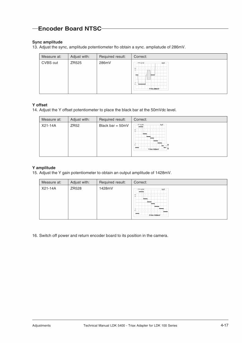
Sync amplitude13. Adjust the sync, amplitude potentiometer fto obtain a sync. ampliatude of 286mV.
Measure at: Adjust with: Required result: Correct:
CVBS out ZR525 286mV
Y offset14. Adjust the Y offset potentiometer to place the black bar at the 50mVdc level.
Measure at: Adjust with: Required result: Correct:
X21-14A ZR52 Black bar = 50mV
Y amplitude15. Adjust the Y gain potentiometer to obtain an output amplitude of 1428mV.
Measure at: Adjust with: Required result: Correct:
X21-14A ZR528 1428mV
16. Switch off power and return encoder board to its position in the camera.
Encoder Board NTSC
0%
10
90
100
0.1V 2µS
VA+286mV
0%
10
90
100
0.2V 5µS
VA+1428mV
0%
10
90
100
0.2V 5µS
VA+1428mV

4-18 Technical Manual LDK 5400 - Triax Adapter for LDK 100 Series Adjustments

Wiring Diagrams Technical Manual LDK 5400 - Triax Adapter for LDK 100 Series 5-1
Section 5
Wiring Diagrams
Contents
Wiring Diagram Triax adapter ............................. 5-2 Wiring Diagram Motherboard Triax ..................... 5-5
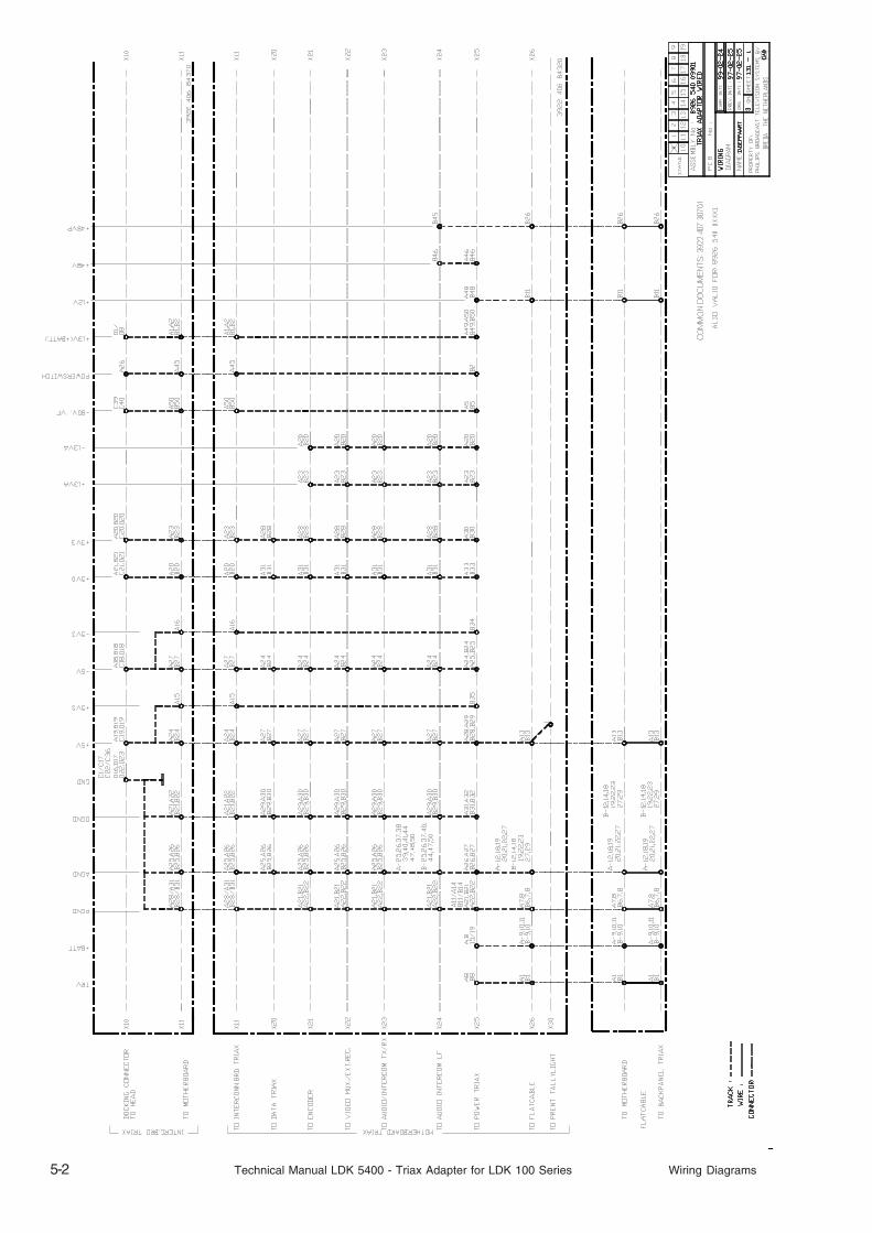
5-2 Technical Manual LDK 5400 - Triax Adapter for LDK 100 Series Wiring Diagrams

Wiring Diagrams Technical Manual LDK 5400 - Triax Adapter for LDK 100 Series 5-3

5-4 Technical Manual LDK 5400 - Triax Adapter for LDK 100 Series Wiring Diagrams

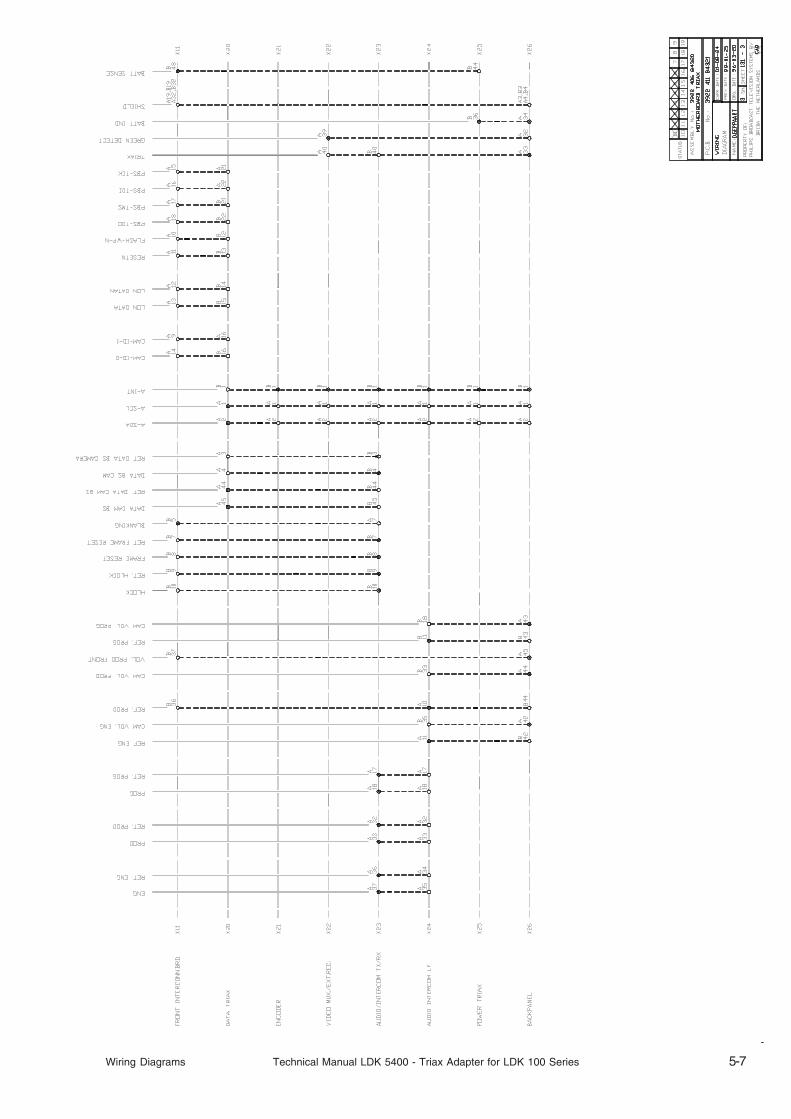
Wiring Diagrams Technical Manual LDK 5400 - Triax Adapter for LDK 100 Series 5-5
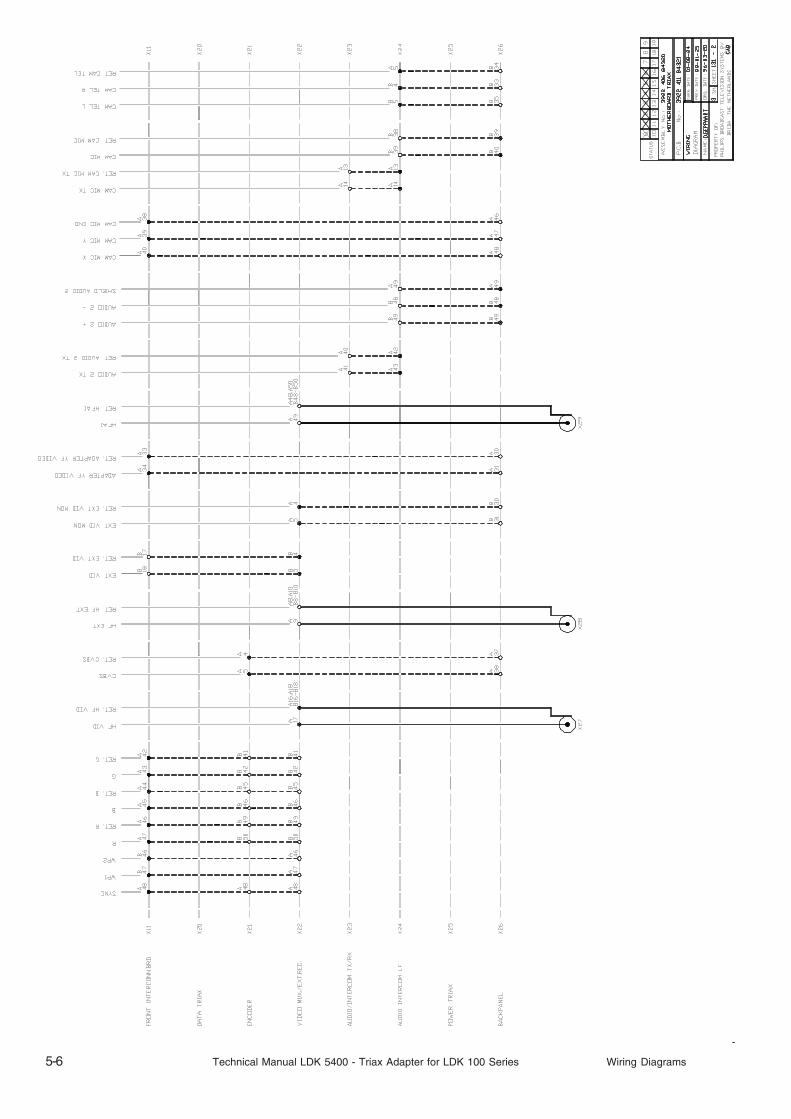
5-6 Technical Manual LDK 5400 - Triax Adapter for LDK 100 Series Wiring Diagrams
Wiring Diagrams Technical Manual LDK 5400 - Triax Adapter for LDK 100 Series 5-7

5-8 Technical Manual LDK 5400 - Triax Adapter for LDK 100 Series Wiring Diagrams

Mechanical Exploded Views Technical Manual LDK 5400 - Triax Adapter for LDK 100 Series 6-1
Section 6
Mechanical Exploded Views
ContentsTriax Adapter ..................................................... 6-2 Triax Adapter Basic ........................................... 6-3

6-2 Technical Manual LDK 5400 - Triax Adapter for LDK 100 Series Mechanical Exploded Views
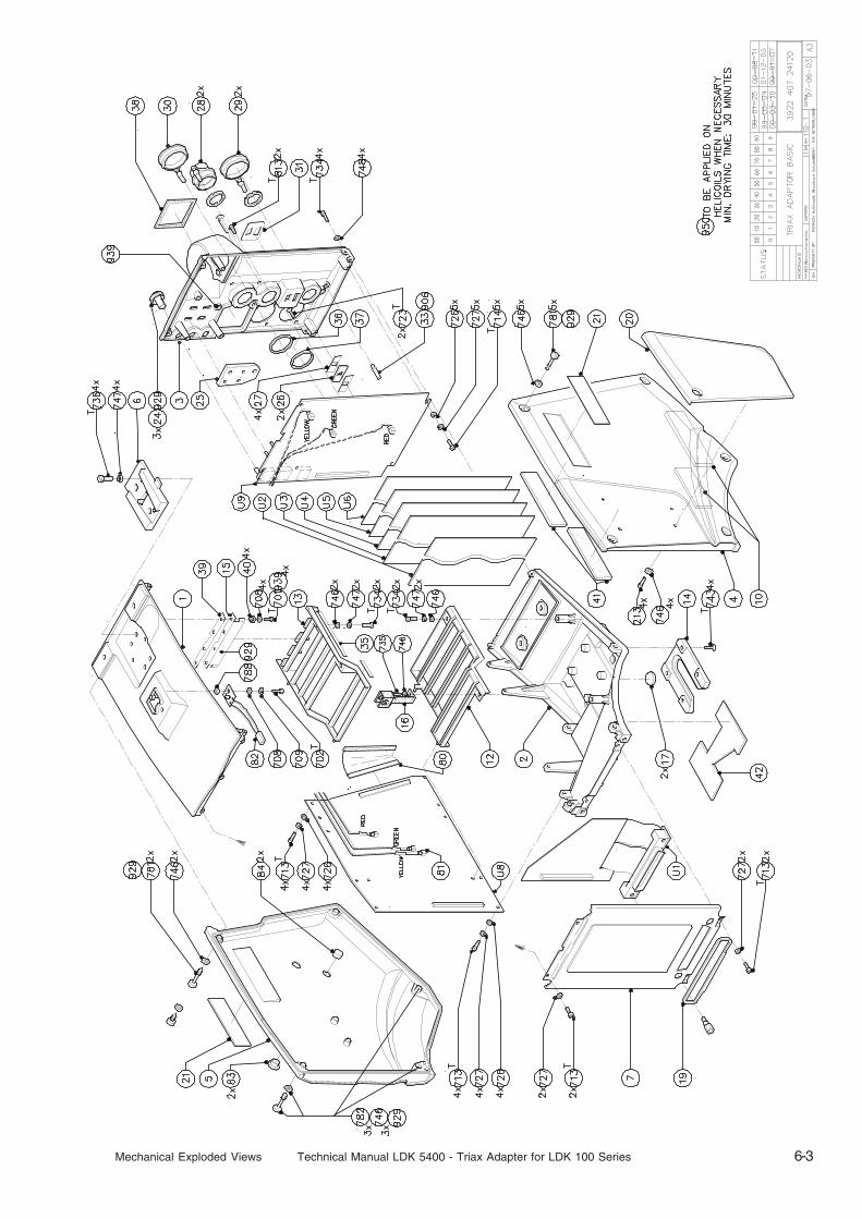
Mechanical Exploded Views Technical Manual LDK 5400 - Triax Adapter for LDK 100 Series 6-3

6-4 Technical Manual LDK 5400 - Triax Adapter for LDK 100 Series Mechanical Exploded Views

Parts Lists Technical Manual LDK 5400 - Triax Adapter for LDK 100 Series 7-1
Section 7
Parts Lists
Item Code Number Description
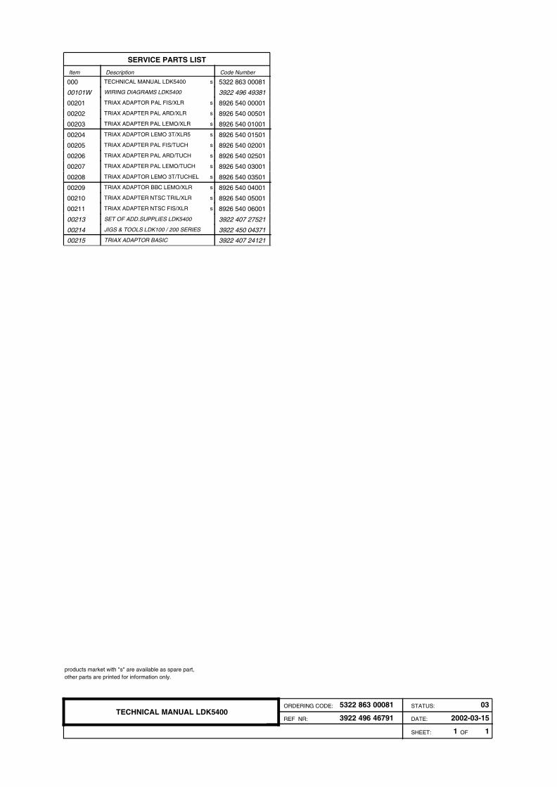
SERVICE PARTS LIST
s000 TECHNICAL MANUAL LDK5400 5322 863 00081
00101W WIRING DIAGRAMS LDK5400 3922 496 49381
s00201 TRIAX ADAPTOR PAL FIS/XLR 8926 540 00001
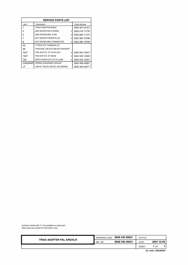
s00202 TRIAX ADAPTER PAL ARD/XLR 8926 540 00501
s00203 TRIAX ADAPTER PAL LEMO/XLR 8926 540 01001
s00204 TRIAX ADAPTOR LEMO 3T/XLR5 8926 540 01501
s00205 TRIAX ADAPTER PAL FIS/TUCH 8926 540 02001
s00206 TRIAX ADAPTER PAL ARD/TUCH 8926 540 02501
s00207 TRIAX ADAPTER PAL LEMO/TUCH 8926 540 03001
s00208 TRIAX ADAPTOR LEMO 3T/TUCHEL 8926 540 03501
s00209 TRIAX ADAPTOR BBC LEMO/XLR 8926 540 04001
s00210 TRIAX ADAPTER NTSC TRIL/XLR 8926 540 05001
s00211 TRIAX ADAPTER NTSC FIS/XLR 8926 540 06001
00213 SET OF ADD.SUPPLIES LDK5400 3922 407 27521
00214 JIGS & TOOLS LDK100 / 200 SERIES 3922 450 04371
00215 TRIAX ADAPTOR BASIC 3922 407 24121
1 1SHEET: OF
3922 496 46791 DATE: 2002-03-15REF NR:
ORDERING CODE: STATUS: 035322 863 00081TECHNICAL MANUAL LDK5400
products market with "s" are available as spare part, other parts are printed for information only.

Item Code Number Description
SERVICE PARTS LIST
1 TRIAX ADAPTOR BASIC 3922 407 24121
s4 FISHER RECEPTACLE WIRED 5322 218 11775
s5 SAM INTERCONN. XLR5 5322 265 11107
s7 NUT DRIVER FISHER PLUG 5322 395 10798
s8 NUT DRIVER BNC CONNECTOR 5322 395 10799
50 TYPEPLATE THOMSON CE
99 PACKAGE LDK100 CAM EN TRIAXADP
s722T CSK SCR STL ST M2,5X6 5322 502 13917
s733T PAN SCR STL ST M3X6 5322 502 14403
s748 EARTH WASH STL ST A4 3,2X6 5322 532 12257
DIAGRWR WIRING DIAGRAMS LDK5400 3922 496 49381
JT JIGS & TOOLS LDK100 / 200 SERIES 3922 450 04371
1 1SHEET: OF
8926 540 00001 DATE: 2001-12-05REF NR:
ORDERING CODE: STATUS:8926 540 00001TRIAX ADAPTOR PAL FIS/XLR
products market with "s" are available as spare part, other parts are printed for information only.
alt. code: LDK5400/00
Item Code Number Description
SERVICE PARTS LIST
1 TRIAX ADAPTOR BASIC 3922 407 24121
s4 ARD RECEPTACLE WIRED 5322 218 11776
s5 SAM INTERCONN. XLR5 5322 265 11107
s7 NUT DRIVER FISHER PLUG 5322 395 10798
s8 NUT DRIVER BNC CONNECTOR 5322 395 10799
50 TYPEPLATE THOMSON CE
99 PACKAGE LDK100 CAM EN TRIAXADP
s722T CSK SCR STL ST A4 M1,6X4 5322 502 14047
s733T PAN SCR STL ST M3X6 5322 502 14403
s748 EARTH WASH STL ST A4 3,2X6 5322 532 12257
DIAGRWR WIRING DIAGRAMS LDK5400 3922 496 49381
JT JIGS & TOOLS LDK100 / 200 SERIES 3922 450 04371
1 1SHEET: OF
8926 540 00501 DATE: 2001-12-05REF NR:
ORDERING CODE: STATUS:8926 540 00501TRIAX ADAPTER PAL ARD/XLR
products market with "s" are available as spare part, other parts are printed for information only.
alt. code: LDK5400/05
Item Code Number Description
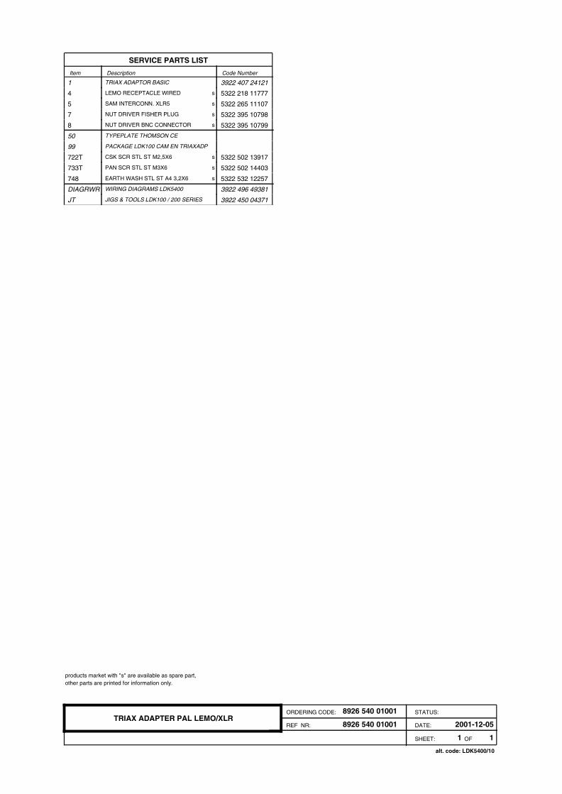
SERVICE PARTS LIST
1 TRIAX ADAPTOR BASIC 3922 407 24121
s4 LEMO RECEPTACLE WIRED 5322 218 11777
s5 SAM INTERCONN. XLR5 5322 265 11107
s7 NUT DRIVER FISHER PLUG 5322 395 10798
s8 NUT DRIVER BNC CONNECTOR 5322 395 10799
50 TYPEPLATE THOMSON CE
99 PACKAGE LDK100 CAM EN TRIAXADP
s722T CSK SCR STL ST M2,5X6 5322 502 13917
s733T PAN SCR STL ST M3X6 5322 502 14403
s748 EARTH WASH STL ST A4 3,2X6 5322 532 12257
DIAGRWR WIRING DIAGRAMS LDK5400 3922 496 49381
JT JIGS & TOOLS LDK100 / 200 SERIES 3922 450 04371
1 1SHEET: OF
8926 540 01001 DATE: 2001-12-05REF NR:
ORDERING CODE: STATUS:8926 540 01001TRIAX ADAPTER PAL LEMO/XLR
products market with "s" are available as spare part, other parts are printed for information only.
alt. code: LDK5400/10

Item Code Number Description
SERVICE PARTS LIST
1 TRIAX ADAPTOR BASIC 3922 407 24121
s4 LEMO 3T RECEPTACLE WIRED 3922 407 34471
s5 SAM INTERCONN. XLR5 5322 265 11107
s7 NUT DRIVER FISHER PLUG 5322 395 10798
s8 NUT DRIVER BNC CONNECTOR 5322 395 10799
50 TYPEPLATE THOMSON CE
99 PACKAGE LDK100 CAM EN TRIAXADP
s722T CSK SCR STL ST M2,5X6 5322 502 13917
s733T PAN SCR STL ST M3X6 5322 502 14403
s748 EARTH WASH STL ST A4 3,2X6 5322 532 12257
1 1SHEET: OF
8926 540 01501 DATE: 2001-12-05REF NR:
ORDERING CODE: STATUS:8926 540 01501TRIAX ADAPTOR LEMO 3T/XLR5
products market with "s" are available as spare part, other parts are printed for information only.
alt. code: LDK5400/15

Item Code Number Description
SERVICE PARTS LIST
1 TRIAX ADAPTOR BASIC 3922 407 24121
s4 FISHER RECEPTACLE WIRED 5322 218 11775
s5 SAM INTERCONN.TUCHEL 5322 265 11108
s7 NUT DRIVER FISHER PLUG 5322 395 10798
s8 NUT DRIVER BNC CONNECTOR 5322 395 10799
50 TYPEPLATE THOMSON CE
99 PACKAGE LDK100 CAM EN TRIAXADP
s722T CSK SCR STL ST A4 M1,6X4 5322 502 14047
s733T PAN SCR STL ST M3X6 5322 502 14403
s748 EARTH WASH STL ST A4 3,2X6 5322 532 12257
DIAGRWR WIRING DIAGRAMS LDK5400 3922 496 49381
JT JIGS & TOOLS LDK100 / 200 SERIES 3922 450 04371
1 1SHEET: OF
8926 540 02001 DATE: 2001-12-05REF NR:
ORDERING CODE: STATUS:8926 540 02001TRIAX ADAPTER PAL FIS/TUCH
products market with "s" are available as spare part, other parts are printed for information only.
alt. code: LDK5400/20

Item Code Number Description
SERVICE PARTS LIST
1 TRIAX ADAPTOR BASIC 3922 407 24121
s4 ARD RECEPTACLE WIRED 5322 218 11776
s5 SAM INTERCONN.TUCHEL 5322 265 11108
s7 NUT DRIVER FISHER PLUG 5322 395 10798
s8 NUT DRIVER BNC CONNECTOR 5322 395 10799
50 TYPEPLATE THOMSON CE
99 PACKAGE LDK100 CAM EN TRIAXADP
s722T CSK SCR STL ST A4 M1,6X4 5322 502 14047
s733T PAN SCR STL ST M3X6 5322 502 14403
s748 EARTH WASH STL ST A4 3,2X6 5322 532 12257
DIAGRWR WIRING DIAGRAMS LDK5400 3922 496 49381
JT JIGS & TOOLS LDK100 / 200 SERIES 3922 450 04371
1 1SHEET: OF
8926 540 02501 DATE: 2001-12-05REF NR:
ORDERING CODE: STATUS:8926 540 02501TRIAX ADAPTER PAL ARD/TUCH
products market with "s" are available as spare part, other parts are printed for information only.
alt. code: LDK5400/25
Item Code Number Description
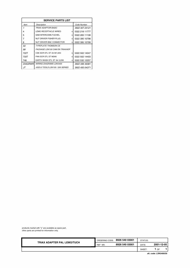
SERVICE PARTS LIST
1 TRIAX ADAPTOR BASIC 3922 407 24121
s4 LEMO RECEPTACLE WIRED 5322 218 11777
s5 SAM INTERCONN.TUCHEL 5322 265 11108
s7 NUT DRIVER FISHER PLUG 5322 395 10798
s8 NUT DRIVER BNC CONNECTOR 5322 395 10799
50 TYPEPLATE THOMSON CE
99 PACKAGE LDK100 CAM EN TRIAXADP
s722T CSK SCR STL ST A4 M1,6X4 5322 502 14047
s733T PAN SCR STL ST M3X6 5322 502 14403
s748 EARTH WASH STL ST A4 3,2X6 5322 532 12257
DIAGRWR WIRING DIAGRAMS LDK5400 3922 496 49381
JT JIGS & TOOLS LDK100 / 200 SERIES 3922 450 04371
1 1SHEET: OF
8926 540 03001 DATE: 2001-12-05REF NR:
ORDERING CODE: STATUS:8926 540 03001TRIAX ADAPTER PAL LEMO/TUCH
products market with "s" are available as spare part, other parts are printed for information only.
alt. code: LDK5400/30

Item Code Number Description
SERVICE PARTS LIST
1 TRIAX ADAPTOR BASIC 3922 407 24121
s4 LEMO 3T RECEPTACLE WIRED 3922 407 34471
s5 SAM INTERCONN.TUCHEL 5322 265 11108
s7 NUT DRIVER FISHER PLUG 5322 395 10798
s8 NUT DRIVER BNC CONNECTOR 5322 395 10799
50 TYPEPLATE THOMSON CE
99 PACKAGE LDK100 CAM EN TRIAXADP
s722T CSK SCR STL ST M2,5X6 5322 502 13917
s733T PAN SCR STL ST M3X6 5322 502 14403
s748 EARTH WASH STL ST A4 3,2X6 5322 532 12257
1 1SHEET: OF
8926 540 03501 DATE: 2001-12-05REF NR:
ORDERING CODE: STATUS:8926 540 03501TRIAX ADAPTOR LEMO 3T/TUCHEL
products market with "s" are available as spare part, other parts are printed for information only.
alt. code: LDK5400/35

Item Code Number Description
SERVICE PARTS LIST
1 TRIAX ADAPTOR BASIC 3922 407 24121
s4 BBC LEMO RECEPTACLE WIRED 5322 218 11774
s5 SAM INTERCONN. XLR5 5322 265 11107
s7 NUT DRIVER FISHER PLUG 5322 395 10798
s8 NUT DRIVER BNC CONNECTOR 5322 395 10799
50 TYPEPLATE THOMSON CE
99 PACKAGE LDK100 CAM EN TRIAXADP
s722T CSK SCR STL ST A4 M1,6X4 5322 502 14047
s733T PAN SCR STL ST M3X6 5322 502 14403
s748 EARTH WASH STL ST A4 3,2X6 5322 532 12257
1 1SHEET: OF
8926 540 04001 DATE: 2001-12-05REF NR:
ORDERING CODE: STATUS:8926 540 04001TRIAX ADAPTOR BBC LEMO/XLR
products market with "s" are available as spare part, other parts are printed for information only.
alt. code: LDK5400/40

Item Code Number Description
SERVICE PARTS LIST
1 TRIAX ADAPTOR BASIC 3922 407 24121
s4 TRILOCK RECEPTACLE WIRED 5322 218 11778
s5 SAM INTERCONN. XLR5 5322 265 11107
s7 NUT DRIVER FISHER PLUG 5322 395 10798
s8 NUT DRIVER BNC CONNECTOR 5322 395 10799
50 TYPEPLATE THOMSON CE
99 PACKAGE LDK100 CAM EN TRIAXADP
s722T CSK SCR STL ST A4 M1,6X4 5322 502 14047
s733T PAN SCR STL ST M3X6 5322 502 14403
s748 EARTH WASH STL ST A4 3,2X6 5322 532 12257
DIAGRWR WIRING DIAGRAMS LDK5400 3922 496 49381
JT JIGS & TOOLS LDK100 / 200 SERIES 3922 450 04371
1 1SHEET: OF
8926 540 05001 DATE: 2001-12-05REF NR:
ORDERING CODE: STATUS:8926 540 05001TRIAX ADAPTER NTSC TRIL/XLR
products market with "s" are available as spare part, other parts are printed for information only.
alt. code: LDK5400/50

Item Code Number Description
SERVICE PARTS LIST
1 TRIAX ADAPTOR BASIC 3922 407 24121
s4 FISHER RECEPTACLE WIRED 5322 218 11775
s5 SAM INTERCONN. XLR5 5322 265 11107
s7 NUT DRIVER FISHER PLUG 5322 395 10798
s8 NUT DRIVER BNC CONNECTOR 5322 395 10799
50 TYPEPLATE THOMSON CE
99 PACKAGE LDK100 CAM EN TRIAXADP
s722T CSK SCR STL ST M2,5X6 5322 502 13917
s733T PAN SCR STL ST M3X6 5322 502 14403
s748 EARTH WASH STL ST A4 3,2X6 5322 532 12257
DIAGRWR WIRING DIAGRAMS LDK5400 3922 496 49381
JT JIGS & TOOLS LDK100 / 200 SERIES 3922 450 04371
1 1SHEET: OF
8926 540 06001 DATE: 2001-12-05REF NR:
ORDERING CODE: STATUS:8926 540 06001TRIAX ADAPTER NTSC FIS/XLR
products market with "s" are available as spare part, other parts are printed for information only.
alt. code: LDK5400/60

Item Code Number Description
SERVICE PARTS LIST
s1 OPERATOR’S MANUAL LDK5400 5322 863 00079
s2 TECHNICAL MANUAL LDK5400 5322 863 00081
s2D SERVICE MANUAL LDK5400 3922 496 46801
3 SET CAMERACIPHERS MIDDLE
s4 BAG PE 250X410X0,03 5322 600 10768
1 1SHEET: OF
3922 407 27521 DATE: 1999-06-23REF NR:
ORDERING CODE: STATUS:not a spare partSET OF ADD.SUPPLIES LDK5400
products market with "s" are available as spare part, other parts are printed for information only.
Item Code Number Description
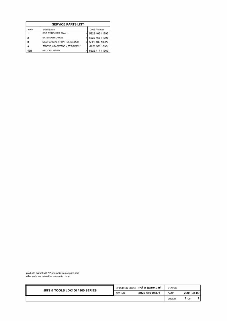
SERVICE PARTS LIST
s1 PCB EXTENDER SMALL 5322 466 11795
s2 EXTENDER LARGE 5322 466 11796
s3 MECHANICAL FRONT EXTENDER 5322 402 10927
4 TRIPOD ADAPTER PLATE LDK5031 8926 503 10001
s45B HELICOL M3-1D 5322 417 11369
1 1SHEET: OF
3922 450 04371 DATE: 2001-02-09REF NR:
ORDERING CODE: STATUS:not a spare partJIGS & TOOLS LDK100 / 200 SERIES
products market with "s" are available as spare part, other parts are printed for information only.

SERVICE PARTS LIST
Item Code Number Description Item Code Number Description
s1 TOPPLATE TRIAX 5322 442 01136
s2 BOTTOMPLATE MACHINED AND LACQ 5322 442 01137
s3 BACKPLATE MACHINED AND LACQUE 5322 426 10543
s4 COVER LEFT 5322 426 10544
s5 COVER RIGHT MACHINED AND LACQ 5322 426 10545
s6 QUICK MOUNT BLOCK ASSY 5322 466 11712
s7 DOCKPLATE ADAPTOR 5322 466 11713
10 CELRUBBER ZK/CR FEST 10X4MM
s12 PRINTRAIL BOTTOM 3922 400 08594
s13 PRINTRAIL TOP 5322 463 11162
s14 V BRACKET LONG 5322 402 10879
s15 COOLING BRACKET 5322 255 10391
s16 INTERCONN.FLEX BRACKET 3922 407 32931
s17 FOOT 5322 462 10994
s19 SEALING DOCKPLATE 5322 466 11714
s20 PADDING TRIAX-ADAPTOR 5322 466 11715
s21 WORDMARK 62MM 5322 454 13247
s24 LONG KNOB 5322 410 11459
s25 GASKET 5-FOLD 5322 466 11716
s26 GASKET FOR SLIDESWITCH 5322 466 11717
s27 SHEET FOR SLIDESWITCH 5322 466 11718
s28 DUSTCOVER BNC 5322 462 10995
s29 DUSTCOVER FISCHER/XLR3-M 5322 462 10996
s30 DUSTCOVER XLR3 FEMALE 5322 462 10997
31 TEXTSTICKER ON BACKPANEL
s33 POWER-ON LENS 5322 381 11926
35 LABEL PRINTRAIL
s36 GASKET XLR3 5322 466 11719
s37 GASKET XLR4 5322 466 11721
s38 GASKET HEADSET 5322 466 11722
s39 ISOLATION PLATE 5322 466 11891
s40 ISOLATION BUSH 5322 532 12984
41 CR STRIP 10X2MM SELFADH
s42 STICKER X130 5322 454 13355
s80 ASSY FLETCABLE 68P 5322 320 12165
s81 COAXCABLE ASSY TRIAX ADAPTOR 5322 322 10125
s82 TALLY LIGHT ASSY 5322 320 12166
s83 BUSH 5322 532 11116
s84 CAP 5322 462 50289
85 SET OF ADD.SUPPLIES LDK5400 3922 407 27521
s90 SET OF SOFTWARE LDK5400 3922 407 25051
s93 SERVICE ASSY FLATCABLE 68P 5322 320 12165
s213 PAN TAP SCR F ST T8 2,9X6,5 5322 502 14037
s701T PAN SCR STL ST M2X4 5322 502 14492
s702T PAN SCR STL ST M2X6 5322 502 14494
s708 WASH STL ST 2,2X5 5322 532 12139
s709 SPR WASH STL ST 2,1X4.4 5322 530 84092
s713T PAN SCR STL ST M2,5X6 5322 502 21207
s714T PAN SCR STL ST M2,5X8 5322 502 21208
s723 CSK SCR STL ST M2,5X8 5322 502 21201
s726 WASH STL ST 2,7X6,5 5322 532 12128
s727 SPR WASH STL ST 2,6X5,1 5322 530 80656
s734T PAN SCR STL ST M3X8 5322 502 14405
s736T PAN SCR STL ST M3X12 5322 502 21213
s743T CSK SCR STL ST M3X8 4822 502 13964
s746 WASH STL ST 3,2X7 5322 532 12126
s747 SPR WASH STL ST 3,1X5,7 4822 530 80188
s748 EARTH WASH STL ST A4 3,2X6 5322 532 12257
s781 RSD CH NK SCR STL ST M3X10 RVS 5322 502 13956
s782 RSD CH NK SCR STL ST M3X12 5322 502 13913
s788 WASH PF-CP SH 3,2X7 2522 600 28017
s813 PAN TAP SCR F ST T8 2,9X8 5322 502 14044
906 RUBBER GLUE SYNTHETIC NBR 042
929 GREASE FS 1292
939 SCREW LOCK 222
950 LOCKTITE 480
sU1 INTERCON BOARD TRIAX 5322 214 12524
sU2 DATA BOARD 5322 214 12525
sU3 VIDEO MUX/EXT REC. 5322 214 12526
sU4 AUDIO INT TX/REC 5322 214 12527
sU5 AUDIO INTERC LF 5322 214 12528
sU6 POWER BOARD 5322 214 12529
sU8 MOTHERBOARD TRIAX 5322 214 12531
sU9 TRIAX BACKPANEL 3922 406 89481
1 1SHEET: OF
3922 407 24121 DATE: 2001-12-11REF NR:
ORDERING CODE: STATUS:not a spare partTRIAX ADAPTOR BASIC
products market with "s" are available as spare part, other parts are printed for information only.