Embed Size (px)
Citation preview
Three Dimensional Morphology of Mn Rich Intermetallics in AlSi Alloys Investigated with X-Ray Tomography
Piotr Mikolajczak1,a, Lorenz Ratke2,b 1Institute of Materials Technology, Poznan University of Technology,
Piotrowo 3, 60-965 Poznan, Poland 2Institut für Materialphysik im Weltraum, Deutsches Zentrum für Luft- und Raumfahrt DLR,
Linder Höhe, 51147 Köln, Germany aemail: [email protected],
bemail: [email protected],
Keywords: aluminum alloys, Mn intermetallics, x-ray tomography, melt flow, solidification
Abstract. Elementary Mn has a great importance as neutralizer of Fe intermetallics like β-Al5FeSi,
which have detrimental effect on mechanical characteristics of AlSi alloys. Presence of Mn in AlSi
alloys causes the formation of other intermetallic phases. To understand the effect of solidification
conditions and fluid flow on the microstructure of AlSi-based alloys and the addition of Mn leading
to Mn-based intermetallics, Al-5 wt pct Si 0.2/0.4/1.0 wt pct Mn alloys have been directionally
solidified under defined thermal (gradient 3 K/mm), solidification velocity (0.02-0.12 mm/s) and
fluid flow (rotating magnetic field 6 mT) conditions. The Mn-based intermetallic phases were
studied using 3D X-ray tomography. The tomography has showed three dimensional complicated
structure of Mn phases developed.
Introduction
Al–Si alloys are most widely used aluminum alloys due to their castability, high strength to
weight ratio, corrosion resistance, etc. The main impurities that exist in recycled Al–Si foundry
alloys are iron (Fe), manganese (Mn), copper (Cu), and zinc (Zn). Iron is considered the most
harmful element since its presence enhances the precipitation of many iron intermetallic phases in
the form of long, intercepting platelets (or needles as they appear in the microstructure), and, hence,
unacceptable mechanical properties. Thus, alloying elements such as Mn, Cr, Mo and Be have been
used to replace the acicular β-phase with α-Al(Mn,Fe)Si which has granular or skeleton (or Chinese
script) morphology [1–3].
Several efforts are being directed towards controlling the amount, the morphology and the
distribution of such minority phases (like Fe and Mn phases), formed in situ as particles and
inclusions. One of the methods being discussed in the last years is forced melt flow, generated e.g.
by rotating magnetic field (RMF) [4,5]. Fluid flow is known to have a great influence on the
microstructure formation. Because melt flow is present in all casting technologies, it is important to
understand flow effects on the formation of intermetallic phases in AlSi alloys.
The aim of the present work is to get insight into the three dimensional structure of the Mn
phases using 3D X-ray tomography studying specimens solidifying in various solidification and
flow conditions. Three dimensional presentation of Mn phases and analysis could help in
understanding the processes occurring during solidification of an aluminum ternary AlSiMn alloy
and the effect on the microstructure and alloys properties.
Experimental
This study comprises three aluminum alloys with 5 wt.% Si and 0.2, 0.4 and 1.0 wt.% Mn
prepared from pure components: Al (99.999% Hydro Aluminium Deutschland GmbH), Si (Crystal
Growth Laboratory, Berlin, Germany) and Mn (from Manganese Flake 99.95%, Goodfellow
Cambridge Ltd, UK). The melt was prepared in an electric resistance furnace using a graphite
Materials Science Forum Vols. 790-791 (2014) pp 335-340Online available since 2014/May/09 at www.scientific.net© (2014) Trans Tech Publications, Switzerlanddoi:10.4028/www.scientific.net/MSF.790-791.335
All rights reserved. No part of contents of this paper may be reproduced or transmitted in any form or by any means without the written permission of TTP,www.ttp.net. (ID: 128.6.218.72, Rutgers University Libraries, New Brunswick, USA-11/08/14,11:54:22)
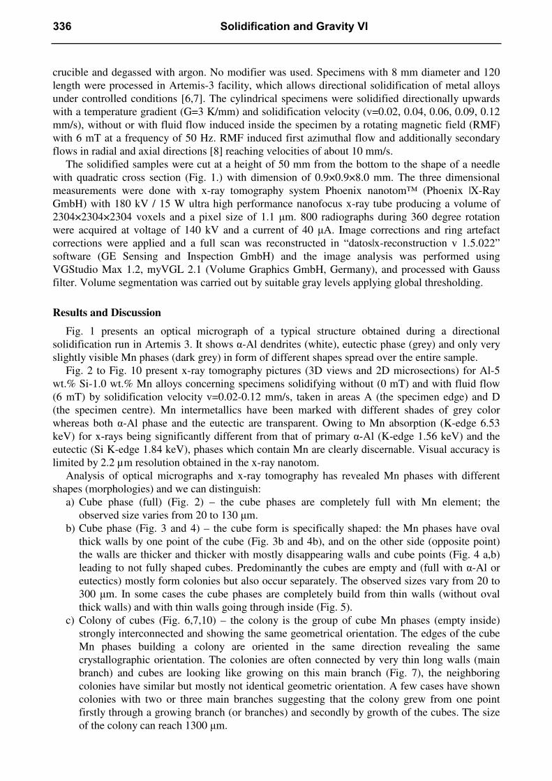
crucible and degassed with argon. No modifier was used. Specimens with 8 mm diameter and 120
length were processed in Artemis-3 facility, which allows directional solidification of metal alloys
under controlled conditions [6,7]. The cylindrical specimens were solidified directionally upwards
with a temperature gradient (G=3 K/mm) and solidification velocity (v=0.02, 0.04, 0.06, 0.09, 0.12
mm/s), without or with fluid flow induced inside the specimen by a rotating magnetic field (RMF)
with 6 mT at a frequency of 50 Hz. RMF induced first azimuthal flow and additionally secondary
flows in radial and axial directions [8] reaching velocities of about 10 mm/s.
The solidified samples were cut at a height of 50 mm from the bottom to the shape of a needle
with quadratic cross section (Fig. 1.) with dimension of 0.9×0.9×8.0 mm. The three dimensional
measurements were done with x-ray tomography system Phoenix nanotom™ (Phoenix |X-Ray
GmbH) with 180 kV / 15 W ultra high performance nanofocus x-ray tube producing a volume of
2304×2304×2304 voxels and a pixel size of 1.1 µm. 800 radiographs during 360 degree rotation
were acquired at voltage of 140 kV and a current of 40 µA. Image corrections and ring artefact
corrections were applied and a full scan was reconstructed in “datos|x-reconstruction v 1.5.022”
software (GE Sensing and Inspection GmbH) and the image analysis was performed using
VGStudio Max 1.2, myVGL 2.1 (Volume Graphics GmbH, Germany), and processed with Gauss
filter. Volume segmentation was carried out by suitable gray levels applying global thresholding.
Results and Discussion
Fig. 1 presents an optical micrograph of a typical structure obtained during a directional
solidification run in Artemis 3. It shows α-Al dendrites (white), eutectic phase (grey) and only very
slightly visible Mn phases (dark grey) in form of different shapes spread over the entire sample.
Fig. 2 to Fig. 10 present x-ray tomography pictures (3D views and 2D microsections) for Al-5
wt.% Si-1.0 wt.% Mn alloys concerning specimens solidifying without (0 mT) and with fluid flow
(6 mT) by solidification velocity v=0.02-0.12 mm/s, taken in areas A (the specimen edge) and D
(the specimen centre). Mn intermetallics have been marked with different shades of grey color
whereas both α-Al phase and the eutectic are transparent. Owing to Mn absorption (K-edge 6.53
keV) for x-rays being significantly different from that of primary α-Al (K-edge 1.56 keV) and the
eutectic (Si K-edge 1.84 keV), phases which contain Mn are clearly discernable. Visual accuracy is
limited by 2.2 µm resolution obtained in the x-ray nanotom.
Analysis of optical micrographs and x-ray tomography has revealed Mn phases with different
shapes (morphologies) and we can distinguish:
a) Cube phase (full) (Fig. 2) – the cube phases are completely full with Mn element; the
observed size varies from 20 to 130 µm.
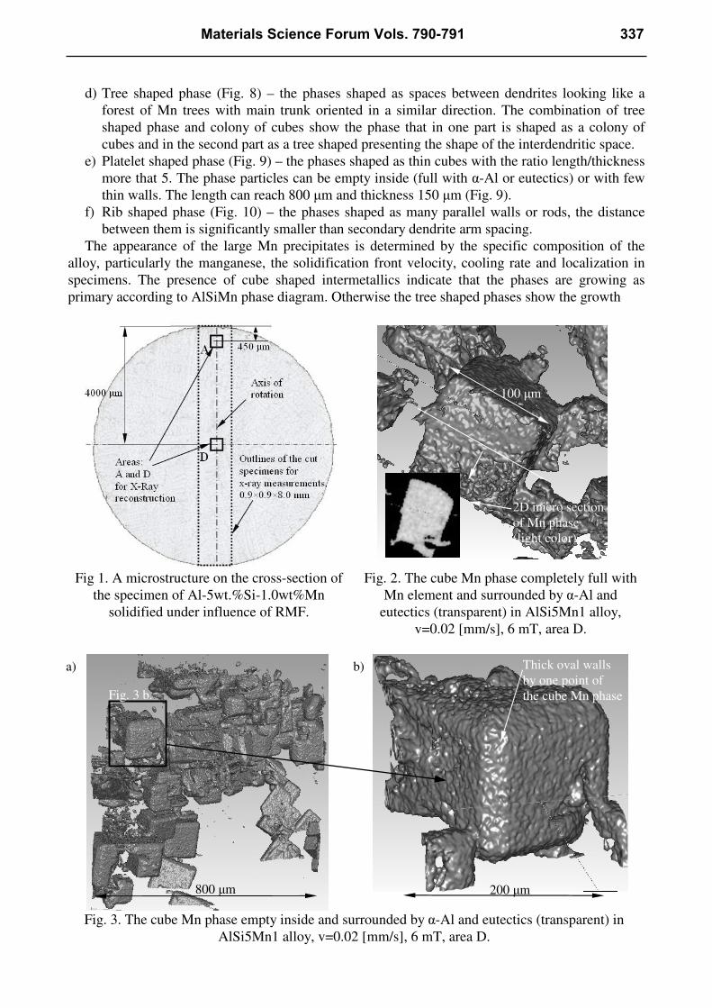
b) Cube phase (Fig. 3 and 4) – the cube form is specifically shaped: the Mn phases have oval
thick walls by one point of the cube (Fig. 3b and 4b), and on the other side (opposite point)
the walls are thicker and thicker with mostly disappearing walls and cube points (Fig. 4 a,b)
leading to not fully shaped cubes. Predominantly the cubes are empty and (full with α-Al or
eutectics) mostly form colonies but also occur separately. The observed sizes vary from 20 to
300 µm. In some cases the cube phases are completely build from thin walls (without oval
thick walls) and with thin walls going through inside (Fig. 5).
c) Colony of cubes (Fig. 6,7,10) – the colony is the group of cube Mn phases (empty inside)
strongly interconnected and showing the same geometrical orientation. The edges of the cube
Mn phases building a colony are oriented in the same direction revealing the same
crystallographic orientation. The colonies are often connected by very thin long walls (main
branch) and cubes are looking like growing on this main branch (Fig. 7), the neighboring
colonies have similar but mostly not identical geometric orientation. A few cases have shown
colonies with two or three main branches suggesting that the colony grew from one point
firstly through a growing branch (or branches) and secondly by growth of the cubes. The size
of the colony can reach 1300 µm.
336 Solidification and Gravity VI
d) Tree shaped phase (Fig. 8) – the phases shaped as spaces between dendrites looking like a
forest of Mn trees with main trunk oriented in a similar direction. The combination of tree
shaped phase and colony of cubes show the phase that in one part is shaped as a colony of
cubes and in the second part as a tree shaped presenting the shape of the interdendritic space.
e) Platelet shaped phase (Fig. 9) – the phases shaped as thin cubes with the ratio length/thickness
more that 5. The phase particles can be empty inside (full with α-Al or eutectics) or with few
thin walls. The length can reach 800 µm and thickness 150 µm (Fig. 9).
f) Rib shaped phase (Fig. 10) – the phases shaped as many parallel walls or rods, the distance
between them is significantly smaller than secondary dendrite arm spacing.
The appearance of the large Mn precipitates is determined by the specific composition of the
alloy, particularly the manganese, the solidification front velocity, cooling rate and localization in
specimens. The presence of cube shaped intermetallics indicate that the phases are growing as
primary according to AlSiMn phase diagram. Otherwise the tree shaped phases show the growth
Fig 1. A microstructure on the cross-section of
the specimen of Al-5wt.%Si-1.0wt%Mn
solidified under influence of RMF.
Fig. 2. The cube Mn phase completely full with
Mn element and surrounded by α-Al and
eutectics (transparent) in AlSi5Mn1 alloy,
v=0.02 [mm/s], 6 mT, area D.
Fig. 3. The cube Mn phase empty inside and surrounded by α-Al and eutectics (transparent) in
AlSi5Mn1 alloy, v=0.02 [mm/s], 6 mT, area D.
100 µm
800 µm 200 µm
Fig. 3 b.
a) b) Thick oval walls
by one point of
the cube Mn phase
2D micro section
of Mn phase
(light color)
Materials Science Forum Vols. 790-791 337
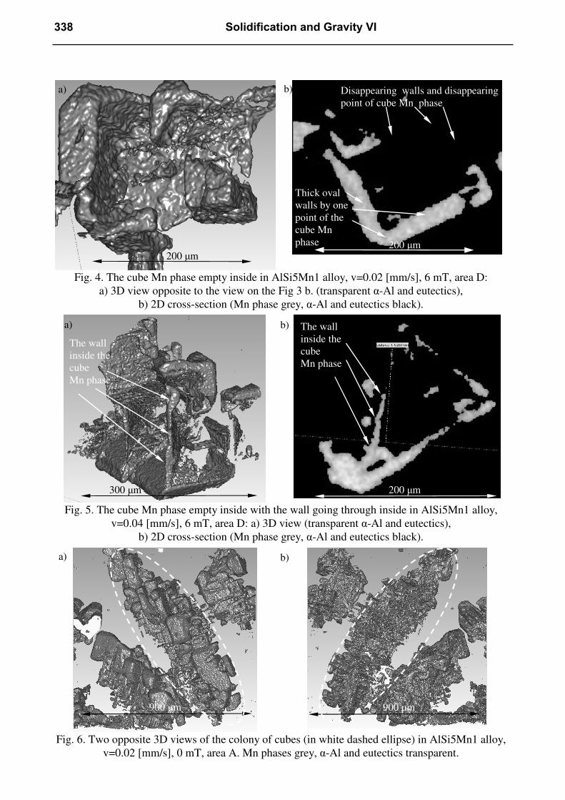
Fig. 4. The cube Mn phase empty inside in AlSi5Mn1 alloy, v=0.02 [mm/s], 6 mT, area D:
a) 3D view opposite to the view on the Fig 3 b. (transparent α-Al and eutectics),
b) 2D cross-section (Mn phase grey, α-Al and eutectics black).
Fig. 5. The cube Mn phase empty inside with the wall going through inside in AlSi5Mn1 alloy,
v=0.04 [mm/s], 6 mT, area D: a) 3D view (transparent α-Al and eutectics),
b) 2D cross-section (Mn phase grey, α-Al and eutectics black).
Fig. 6. Two opposite 3D views of the colony of cubes (in white dashed ellipse) in AlSi5Mn1 alloy,
v=0.02 [mm/s], 0 mT, area A. Mn phases grey, α-Al and eutectics transparent.
200 µm 200 µm
a) b)
300 µm 200 µm
a) b)
900 µm 900 µm
a) b)
The wall
inside the
cube
Mn phase
The wall
inside the
cube
Mn phase
Thick oval
walls by one
point of the
cube Mn
phase
Disappearing walls and disappearing
point of cube Mn phase
338 Solidification and Gravity VI
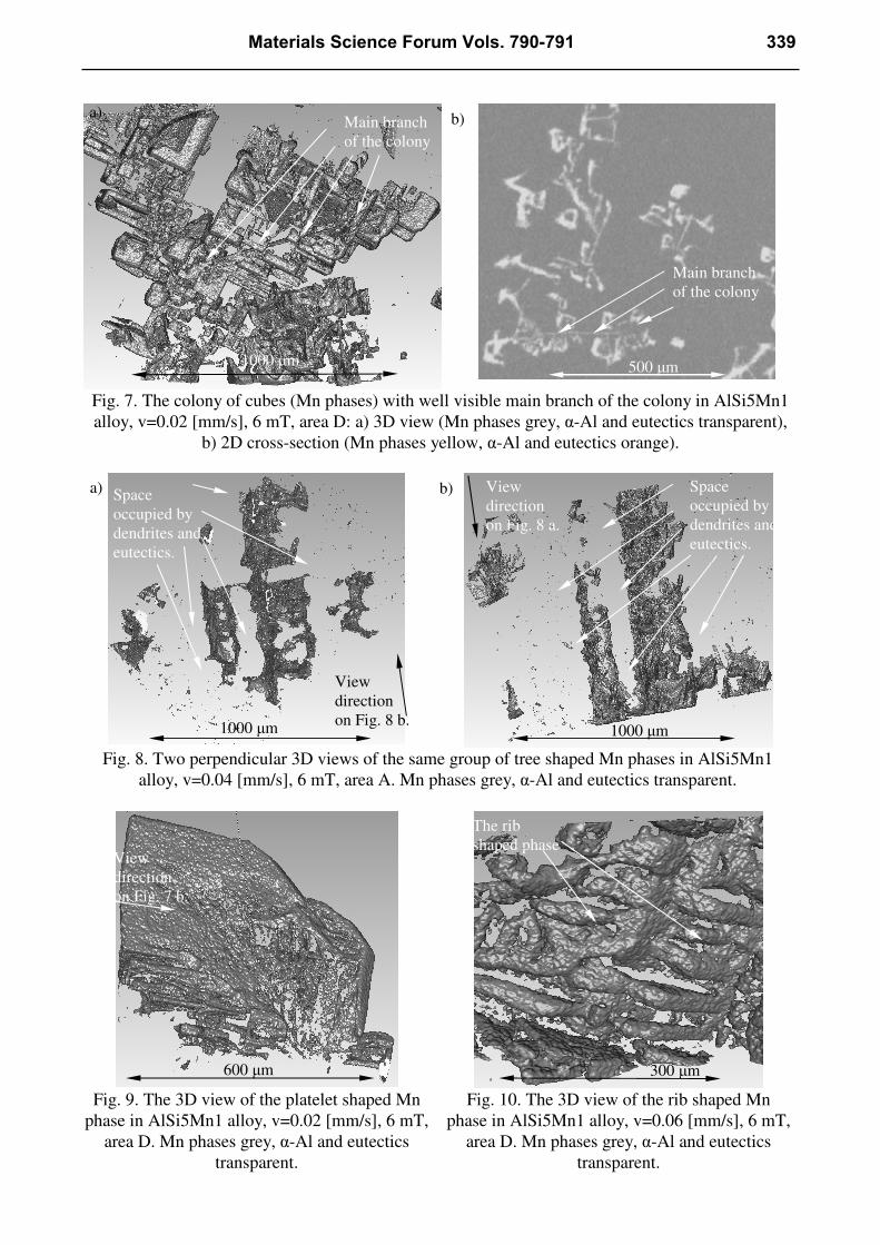
Fig. 7. The colony of cubes (Mn phases) with well visible main branch of the colony in AlSi5Mn1
alloy, v=0.02 [mm/s], 6 mT, area D: a) 3D view (Mn phases grey, α-Al and eutectics transparent),
b) 2D cross-section (Mn phases yellow, α-Al and eutectics orange).
Fig. 8. Two perpendicular 3D views of the same group of tree shaped Mn phases in AlSi5Mn1
alloy, v=0.04 [mm/s], 6 mT, area A. Mn phases grey, α-Al and eutectics transparent.
Fig. 9. The 3D view of the platelet shaped Mn
phase in AlSi5Mn1 alloy, v=0.02 [mm/s], 6 mT,
area D. Mn phases grey, α-Al and eutectics
transparent.
Fig. 10. The 3D view of the rib shaped Mn
phase in AlSi5Mn1 alloy, v=0.06 [mm/s], 6 mT,
area D. Mn phases grey, α-Al and eutectics
transparent.
1000 µm 500 µm
a) b)
1000 µm 1000 µm
a) b)
600 µm 300 µm
View
direction
on Fig. 7 b.
View
direction
on Fig. 8 b.
View
direction
on Fig. 8 a.
Space
occupied by
dendrites and
eutectics.
Space
occupied by
dendrites and
eutectics.
Main branch
of the colony
Main branch
of the colony
The rib
shaped phase
Materials Science Forum Vols. 790-791 339
between dendrites as possible for Mn phases. The phases partially being cube shaped and tree
shaped depict that such formation can form on the boundary of dendritic and eutectic areas in cast
pieces. The Mn intermetallics form not only small cubes (cubic) structures but also complicated and
large (reaching above 1000 µm) structures influencing the alloys properties.
The cubic morphology is compatible with phases in [9] but for AlMn1Si3 modified with 0.17%
diboride. Cubes where located in [9] in bands perpendicular to solidification direction for low
solidification velocity and we have not observed such distributions at the process conditions used.
Mn intermetallics can be observed in X-ray only for AlSi5Mn1 alloy, despite much smaller
phases are also present on microsections for AlSi5Mn0.2/0.4. For the chosen solidification
parameters, e.g. v=0.02 Mn intermetallics present the same morphology in case without and with
forced melt flow and RMF controlled convection seems not determine the shapes of Mn
precipitates. Also the place of measurement, near the specimen surface (area A) or the specimen
center (area D) shows similar Mn phases.
Summary
Three-dimensional models of Mn intermetallics in the controlled solidification and flow condition
in AlSi5Mn0.2/0.4/1.0 alloys have been produced by X-ray tomography. The Mn-rich phases were
observed to exhibit six distinct morphologies: cube shaped (full), cube shaped, colony of cubes, tree
shaped, platelet shaped and rib shaped. The Mn precipitates were observed to form an interlocking
network and to grow as primary phase and also around pre-existing dendrites.
Acknowledgments
This work was carried out in the framework of the “DLR-DAAD-Fellowships” (project no
A/11/95296) at the German Aerospace Center DLR in Cologne.
References
[1] L.A. Narayanan, F.H. Samuel, J.E. Gruzleski, Crystallization Behavior of Iron-Containing
Intermetallic Compounds in 319 Aluminum Alloy. Metall. Mater. Trans. A 25 (1994) 1761.
[2] S. Shivkumar, S. Ricci, C. Keller, Effect of Solution Treatment Parameters on Tensile Properties
of Cast Aluminum Alloys. J. Heat Treat. 8 (1990) 63.
[3] G. Gustafsson, T. Thorvaldsson, G.L. Dunlop, The Influence of Fe and Cr on the Microstructure
of Cast Al-Si-Mg Alloys. Metall. Trans. 17A (1986) 45.
[4] S. Steinbach, L. Ratke, Fluid Flow Effects on Intermetallic Phases in Al-cast Alloys. Trans.
Indian Met., April-June 2007, vol. 60, Nos. 2-3, 137-141.
[5] S. Steinbach, et al., The Influence of Fluid Flow on Intermetallic Phases in Al-cast Alloys.
Materials Science Forum 2006, vols. 519-521, 1795-1800.
[6] J. Alkemper, et al., Directional solidification in an aerogel furnace with high resolution optical
temperature measurements. J. Cryst. Growth, 1998, vol. 191, pp. 252–60.
[7] S. Steinbach, Einfluss von Strömungen auf die Entwicklung des Mikrogefüges bei der
gerichteten Erstarrung von Al-Si und Al-Si-Mg Legierungen. Ph.D. Thesis, RWTH, Aachen, 2005.
[8] M. Hainke, Computation of Convection and Alloy Solidification with the Software Package
CrysVUn Ph.D. Thesis, Technical Faculty Erlangen-Nuremberg, Germany, 2004.
[9] S. Ebzeeva, L. Froyen, Symbiotic univariant eutectic growth in an ternary Al-alloy. Proceedings
of the 5th Decennial Conference on Solidification Processing, Sheffield, UK, 2007.
340 Solidification and Gravity VI

Solidification and Gravity VI 10.4028/www.scientific.net/MSF.790-791 Three Dimensional Morphology of Mn Rich Intermetallics in AlSi Alloys Investigated with X-Ray
Tomography 10.4028/www.scientific.net/MSF.790-791.335