Embed Size (px)
Citation preview
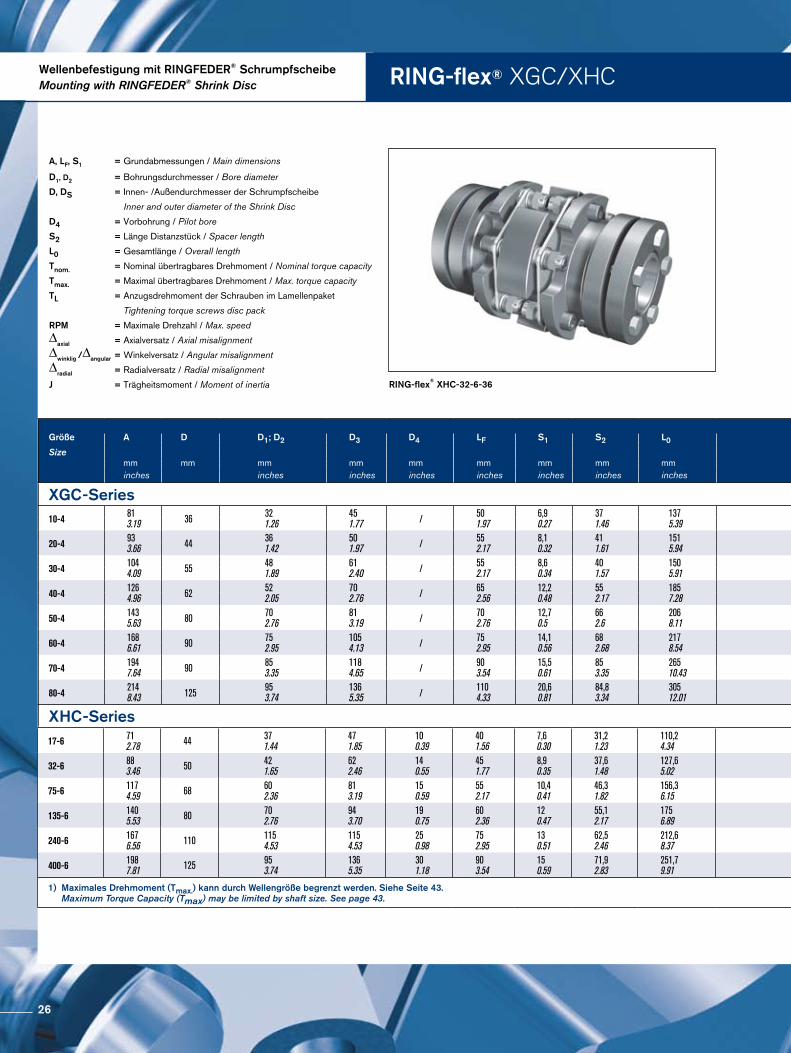
RING-flex®
Torsionssteife LamellenkupplungenTorsionally Rigid Disc Couplings
D|GB09|2009
Partner for performancewww.gerwah.com

Wir sind für Sie da
A Global Presence For You
Die heutige RINGFEDER POWER TRANSMISSION GMBH wurde 1922 in Krefeld / Deutschland als Patentverwertungsgesellschaft für Reibungsfedern entwickelt. Heute sind wir ein weltweiter Anbieter für Spitzenprodukte der Antriebs und Dämpfungstechnik. Innovatives Denken in die Grenzbereiche des Möglichen zeichnet uns aus und hilft uns, mit progressiven und günstigen Lösungen den technischen Fortschritt unserer Kunden zu unterstützen.
The RINGFEDER POWER TRANSMISSION GMBH was founded in 1922 in Krefeld, Germany to fabricate and promote Friction Spring technol-ogy. Today we have expanded our offerings to top power transmission and damping products. In-novative thinking sets us apart and allows us to develop progressive and economical solutions to support our customers.
2

Besondere Anforderungen erfordern beson-dere Anstrengungen
Wir stehen Ihnen mit langjähriger Erfahrung und produktivem Engineering zur Verfügung ob mit Standardprodukten oder auf individuelle Anfrage. Wir verste hen Dinge wie außer gewöhnlich hohe Belastbarkeit oder Montage, Demontagefreundlichkeit von Bauteilen, aber auch die Senkung von Fertigungskosten als „Dienst am Kunden“ und ent
wickeln effiziente und technisch ausgereifte Lösungen.
Special applications require special solutions
Our extensive range of R INGFEDER POWER TRANSMISSION products can be applied to solve most
applications. We don´t just sell, but by understanding the individual requirements of our customers (e.g. loads on the components, easy installation/re-moval capability and reduction of production costs) assist you in every step with innovative engineering to plan efficient and technically mature solutions.
3
Einführung · Introduction RING-flex®
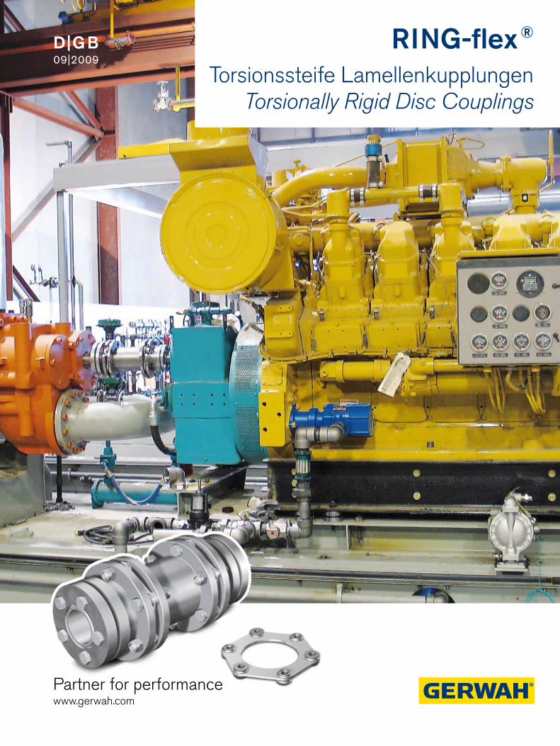
Torsionssteife, flexible Lamellenkupplungen
RINGflex® spielfreie Kupplungen aus 100 % Stahl. Das Herzstück dieser Kupplung besteht aus einem mit Hilfe von FEMAnalysen entwickelten Lamellenpaket aus rostfreiem Federstahl. Mittels exakter Präzisionsbuchsen und hoch belastbaren Schrauben werden die Stahlnaben mit den Lamellenpaketen verbunden.
Je nach Kundenanforderung können die Naben auf unterschiedliche Art und Weise auf den Wellen befestigt werden, z. B. mittels Schrumpf scheiben oder besonders kostengünstig mit Spannsätzen. So ist eine wirklich spielfreie Verbindung der beiden Wellenenden problemlos und einfach gewährleistet.
Die Lamellenpakete gewährleisten hohe übertragbare Drehmomente, ermöglichen gleichzeitig aber den Ausgleich von axialen, radialen und winkligen Fluchtungsfehlern.
Torsionally Stiffness, Flexible Multiple-Disc Couplings
RING-flex®, Backlash-Free Couplings are a 100% steel construc-tion. The flexible portion of this coupling consists of a disc pack developed with the help of FEM analysis and made of stainless steel. The steel hubs are connected to the disc packs by means of preci-sion sleeves and highly resilient bolts.
Depending on customer requirements, the hubs can be attached to the shafts in different ways, e.g. by means of Shrink Disc or - par-ticularly inexpensive - with Locking Assemblies. This guarantees a really backlash-free connection of the two shaft ends that is simple and trouble free.
The disc packs guarantee high transmissible torques while compen-sating for axial, radial and angular misalignments.
axialer Versatz / axial misalignment radialer Versatz / radial misalignment winkliger Versatz / angular misalignment
4
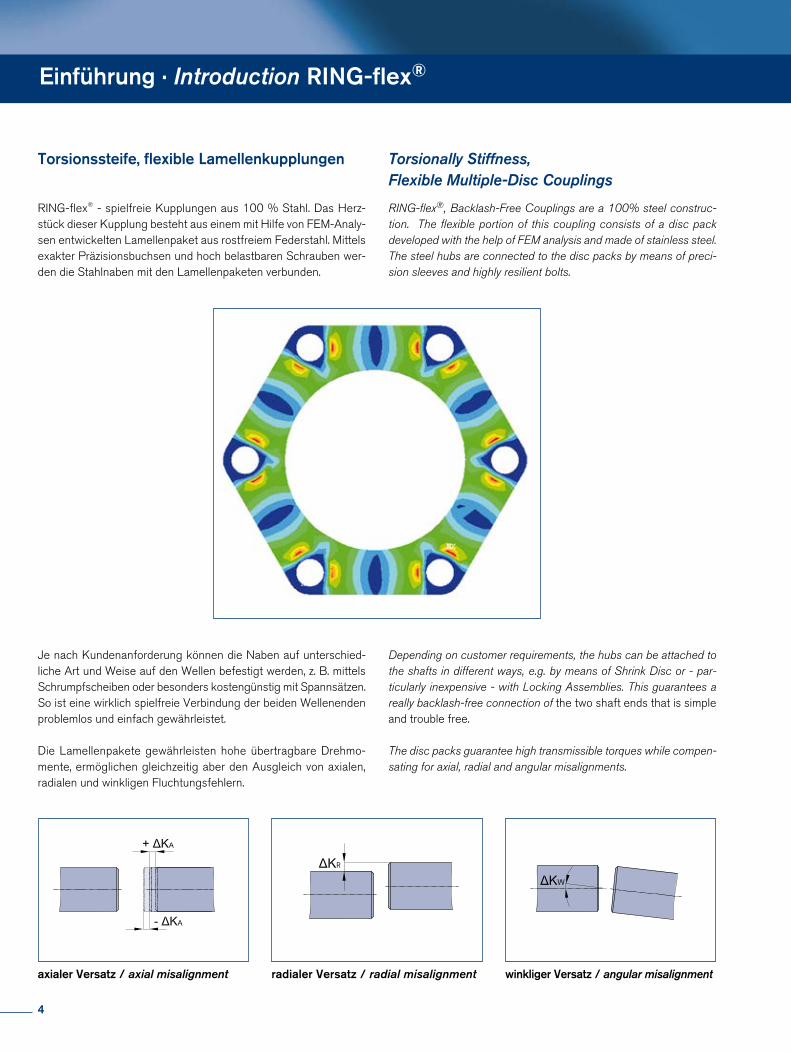
Inhalt · Content
02 Neue Imageseiten New Pages Corporate Image
04 Einführung RING-flex®
Introduction RING-flex®
05 Inhalt / Content
06 Grundlagen RING-flex® Kupplungen Basics of RING-flex® Couplings
Wellenbefestigung mit Passfeder Mounting with key
08 Eigenschaften / Characteristics10 RING-flex® GS/HS12 RING-flex® GD14 RING-flex® HD 16 RING-flex® GC/HC18 RING-flex® HD-FL
Wellenbefestigung mit RINGFEDER®
Schrumpfscheibe Mounting with RINGFEDER® Shrink Disc
20 Eigenschaften / Characteristics22 RING-flex® XGS/XHS24 RING-flex® XGD/XHD26 RING-flex® XGC/XHC28 RING-flex® XHD-FL
Wellenbefestigung mit RINGFEDER® Spannsatz / Mounting with RINGFEDER® Locking Assembly
30 Eigenschaften / Characteristics32 RING-flex® LHS34 RING-flex® LHD36 RING-flex® LHC38 Zusatztabelle / Additional Table
Wellenbefestigung mit Klemmbefestigung Mounting with Clamping Hub
40 Eigenschaften / Characteristics42 RING-flex® CCS44 RING-flex® CCD46 RING-flex® CHS48 RING-flex® CHD50 RING-flex® CHC
52 Technische Hinweise Technical Information
66 FAX-Anfrage / FAX Inquiry
67 Wir bieten ebenfalls an / We also offer
Alle technischen Daten und Hin weise sind unverbindlich. Rechts ansprüche können daraus nicht abgeleitet werden. Der Anwender ist grundsätzlich verpflichtet zu prü-fen, ob die dargestellten Produkte seinen Anforderungen genügen. Änderungen, die dem technischen Fortschritt dienen, behalten wir uns jederzeit vor. Mit Erscheinen dieses Kataloges werden alle älteren Prospekte und Fragebögen zu den gezeigten Produkten ungültig.
All technical details and information is non-binding and cannot be used as a basis for legal claims. The user is obligated to determine whether the represented products meet his requirements. We reserve the right at all times to carry out modifications in the interests of technical progress. Upon the issue of this catalogue all previous brochures and questionnaires on the products displayed are no longer valid.
5
Grundlagen RING-flex® Kupplung · Basics of RING-flex® Coupling
RING-flex®: Die Vorteile des Systems
1. Kein ZahnflankenspielEine wichtige Eigenschaft für den Gebrauch im Synchronbetrieb oder für Maschinen in häufigem Start/Stop oder Reversier betrieb. Beson ders für Anwendungen, in denen die Positionier genauigkeit der Steuerung in beide Richtungen von Bedeutung ist, sind die RINGflex®Kupplungen bestens geeignet.
2. Verdrehsteifigkeit Die Kupplungskonstruktion garantiert hohe Verdrehsteifigkeit, eine wichtige Eigenschaft für Anwendungen in Verpackungs maschinen, Servomotoren, Druckpressen und Werkzeug maschinen.
3. Hohe Temperaturen RINGflex®Kupplungen ermöglichen den Einsatz unter extremsten Temperaturbedingungen bis zu 240 °C/460 °F, z.B. in der Anwendung in HochtemperaturFlüssigkeitspumpen.
4. Hohe GeschwindigkeitenRINGflex® ermöglicht durch die sehr engen HerstellungsToleranzen hohe Rundlaufgenauigkeiten und ist folglich für Anwen dungen bei hohen Geschwindigkeiten, auch bei unregelmäßigen Drehkräften, einsetzbar. 5. Hohe LebensdauerDas hochpräzise Lamellenpaket sorgt für eine optimale Kraftverteilung und die Flexibilität schützt das Getriebe auch vor Erschütterungen durch den Antrieb. Die RINGflex®Kupplungen arbeiten fast verschleißfrei und somit ist eine lange Lebensdauer gewährleistet.
6. Wartungsfreier BetriebRINGflex®Kupplungen sind wartungsfrei und es ist nicht notwendig die Kupplungen zu schmieren oder zu säubern.
RING-flex®: The Advantages of the System
1. No Tooth BacklashAn important property for synchronous operation or for machines that are frequently used in start/stop or reverse operation. RING-flex® couplings are ideally suited to applications in which the positioning accuracy of the control system in both directions is important.
2. Torsional Stiffness The design of the coupling guarantees a high level of torsional stiff-ness, which is an important property for applications in packaging machines, servomotors drives, printing presses and machine tools.
3. High Temperatures RING-flex® couplings can be used under extreme temperature con-ditions up to 240 °C/460 °F, e.g. in high-temperature fluid pumps.
4. High SpeedsDue to the very strict production tolerances, RING-flex® allows pre-cise vertical alignment and a high level of true running accuracy, making it ideal for applications involving high speeds even with irre-gular rotary forces. 5. High Service LifeThe highly accurate disc pack insures optimum force distribution, while its flexibility also protects against vibrations from the drive. RING-flex® couplings do not wear, so that a long service life is guaranteed
6. Maintenance-Free OperationRING-flex® couplings are maintenance-free and do not require gre-asing or cleaning
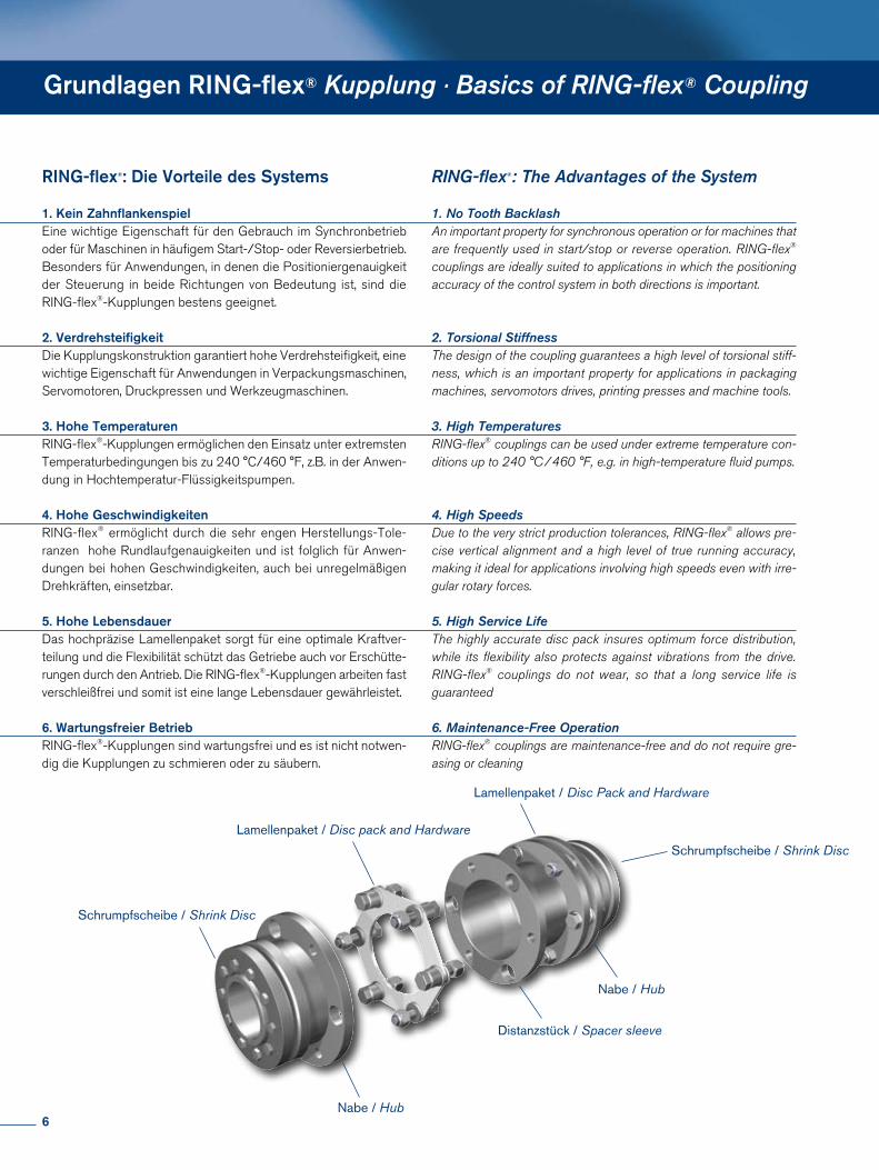
Schrumpfscheibe / Shrink Disc
Nabe / Hub
Nabe / Hub
Distanzstück / Spacer sleeve
Lamellenpaket / Disc pack and Hardware
Schrumpfscheibe / Shrink Disc
Lamellenpaket / Disc Pack and Hardware
6
Lamellenpaket mit Buchsen zu einer Einheit verpresst Laminated Disc Pack
Winkelversatz 0,5° pro Lamellenpaket Angular misalignment 0,5° per disc pack
Höhere Drehmomente Higher torque
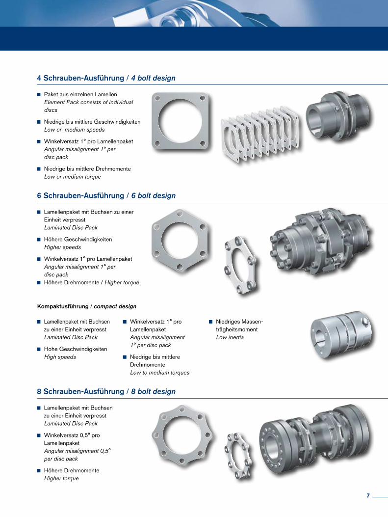
Paket aus einzelnen Lamellen Element Pack consists of individual discs
Niedrige bis mittlere Geschwindigkeiten Low or medium speeds
Winkelversatz 1° pro Lamellenpaket Angular misalignment 1° per disc pack
Niedrige bis mittlere Drehmomente Low or medium torque
Lamellenpaket mit Buchsen zu einer Einheit verpresst Laminated Disc Pack
Höhere Geschwindigkeiten Higher speeds
Winkelversatz 1° pro Lamellenpaket Angular misalignment 1° per disc pack
Höhere Drehmomente / Higher torque
Lamellenpaket mit Buchsen zu einer Einheit verpresst Laminated Disc Pack
Hohe Geschwindigkeiten High speeds
Winkelversatz 1° pro Lamellenpaket Angular misalignment 1° per disc pack
Niedrige bis mittlere Drehmomente Low to medium torques
Niedriges Massen- trägheitsmoment Low inertia
4 Schrauben-Ausführung / 4 bolt design
6 Schrauben-Ausführung / 6 bolt design
Kompaktusführung / compact design
8 Schrauben-Ausführung / 8 bolt design
7
Eigenschaften · Characteristics
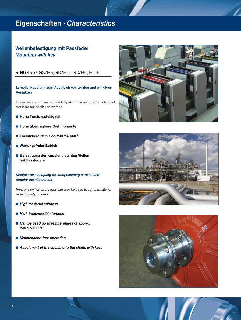
Lamellenkupplung zum Ausgleich von axialen und winkligen Versätzen
Bei Ausführungen mit 2 Lamellenpaketen können zusätzlich radiale Versätze ausgeglichen werden.
Hohe Torsionssteifigkeit
Hohe übertragbare Drehmomente
Einsatzbereich bis ca. 240 °C/460 °F
Wartungsfreier Betrieb
Befestigung der Kupplung auf den Wellen mit Passfedern
Multiple-disc coupling for compensating of axial and angular misalignments
Versions with 2 disc packs can also be used to compensate for radial misalignments.
High torsional stiffness
High transmissible torques
Can be used up to temperatures of approx. 240 °C/460 °F
Maintenance-free operation
Attachment of the coupling to the shafts with keys
Wellenbefestigung mit PassfederMounting with key
RING-flex® GS/HS, GD/HD, GC/HC, HDFL
8
RING-flex® GS/HS, GD/HD, GC/HC, HD, HDFL
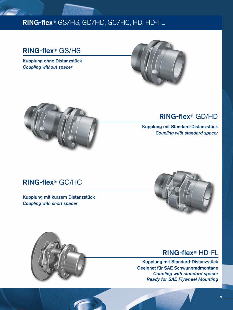
Kupplung ohne DistanzstückCoupling without spacer
RING-flex® GS/HS
Kupplung mit Standard-DistanzstückCoupling with standard spacer
RING-flex® GD/HD
Kupplung mit kurzem DistanzstückCoupling with short spacer
RING-flex® GC/HC
Kupplung mit Standard-DistanzstückGeeignet für SAE Schwungradmontage
Coupling with standard spacerReady for SAE Flywheel Mounting
RING-flex® HD-FL
9
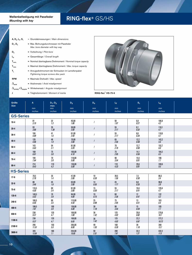
RING-flex® GS/HSWellenbefestigung mit PassfederMounting with key
RING-flex® HS-75-6
A, D3, LF, S1 = Grundabmessungen / Main dimensions
D1, D2 = Max. Bohrungsdurchmesser mit Passfeder Max. bore diameter with key way
D4 = Vorbohrung / Pilot bore
L0 = Gesamtlänge / Overall length
Tnom. = Nominal übertragbares Drehmoment / Nominal torque capacity
Tmax. = Maximal übertragbares Drehmoment / Max. torque capacity
TL = Anzugsdrehmoment der Schrauben im Lamellenpaket Fightening torque screws disc pack
RPM = Maximale Drehzahl / Max. speed
∆axial = Axialversatz / Axial misalignment
∆winklig /∆angular = Winkelversatz / Angular misalignment
J = Trägheitsmoment / Moment of inertia
Größe A D1; D2 D3 D4 LF S1 L0 Größe Tnom. Tmax. TL RPM ∆axial ∆winklig Masse J Size max. Size ∆angular Weight
mm mm mm mm mm mm mm Nm Nm Nm 1/min ± mm grad kg kg m2
inches inches inches inches inches inches inches in-lbs in-lbs ft-lbs ± inches degree lbs lb in2
GS-Series GS-Series 10-4 81
3.19 32 1.3
45,00 1.80 / 50
1.97 6,9 0.27
106,9 4.2 10-4 90
797 135 1.195
11 8 4.500 1,4
0.1 1 1,2 2.6
0,0 2.5
20-4 93 3.66
35 1.38
50,00 2.00 / 55
2.17 8,1 0.32
118,1 4.7 20-4 180
1.593 270 2.390
23 17 4.300 1,5
0.1 1 1,8 4
0,0 5.0
30-4 104 4.09
41 1.6
61,00 2.40 / 55
2.17 8,6 0.34
118,6 4.7 30-4 250
2.213 375 3.319
23 17 4.200 1,8
0.1 1 2,4 5.3
0,0 8.6
40-4 126 4.96
48 1.9
70,00 2.80 / 65
2.56 12,2 0.48
142,2 5.6 40-4 570
5.045 855 7.567
54 40 4.000 2,1
0.1 1 4,3 9.5
0,0 22.5
50-4 143 5.63
54 2.1
81,00 3.20 / 70
2.76 12,7 0.50
152,7 6.0 50-4 890
7.877 1.335 11.816
79 58 3.800 2,4
0.1 1 6,7 14.8
0,0 44.3
60-4 168 6.61
75 3.0
105,00 4.10 / 75
2.95 14,1 0.56
164,2 6.5 60-4 1.140
10.090 1.710 15.135
79 58 3.600 3,2
0.1 1 9,1 20.1
0,0 93.3
70-4 194 7.64
70 2.8
118,00 5.00 / 90
3.54 15,5 0.61
196 7.7 70-4 1.800
15.931 2.700 23.897
156 115 3.000 3,5
0.1 1 16,4 36.2
0,1 201.6
80-4 214 8.43
110 4.3
136,00 5.00 / 110
4.33 20,6 0.81
240,6 9.5 80-4 2.450
21.684 3.675 32.526
156 115 3.000 4
0.2 1 23,2 51.1
0,1 349.5
HS-Series HS-Series 17-6 70,5
2.78 35 1.4
47,00 2.00
10 0.39
39,5 1.56
7,5 0.30
86,5 3.4 17-6 170
1505 290 2.567
8 6 8.400 0,5
0.0 1 1,3 2.8
0,0 1.7
32-6 88 3.46
45 1.8
63,00 2.00
14 0.55
45 1.77
8,8 0.35
98,8 3.9 32-6 320
2832 560 4.956
14 10 6.800 0,6
0.0 1 2,5 5.4
0,0 5.6
75-6 116,5 4.59
60 2.4
81,00 3.00
15 0.59
55 2.17
10,4 0.41
120,4 4.7 75-6 750
6638 1310 11.594
31 23 5.400 0,8
0.0 1 5,2 11.5
0,0 33.9
135-6 140,5 5.53
70 2.8
94,00 4.00
19 0.75
60 2.36
12 0.47
132 5.2 135-6 1350
11949 2.360 20.888
62 46 4.600 1
0.0 1 8,2 18.1
0,0 46.4
240-6 166,5 6.56
90 3.5
115,00 4.50
25 0.98
75 2.95
13 0.51
163 6.4 240-6 2400
21242 4.200 37.173
110 81 3.800 1,2
0.1 1 14,7 32.4
0,0 118.7
400-6 198,5 7.81
100 3.9
136,00 5.00
30 1.18
90 3.54
15 0.59
195 7.7 400-6 4000
35403 7.000 61.955
180 133 3.400 1,4
0.1 1 25 55.1
0,1 285.9
650-6 238 9.37
120 4.7
169,00 7.00
36 1.42
125 4.92
20,8 0.82
270,8 10.7 650-6 6500
57530 11.370 100.633
280 207 3.000 1,7
0.1 1 48,7 107.4
0,2 778.1
1100-6 238 120 169,00 36
1.42 125 22,2 272,2
1100-6 11000 19.250 320
3.000 1,2
0,70 49 0,228
9.37 4.7 6.65 4.92 0.87 10.72 97360 170370 263 0.05 107 778W
2100-8 295 11.61
150 5.9
205,00 8.00
49 1.93
160 6.30
28 1.10
348 13.7 2100-8 21000
185866 36750 325265
570 421 2.500 1,1
0.0 0,5 93 205
0,7 2406.1
3600-8 345 13.58
180 7.1
254,00 10.00
59 2.32
200 7.87
32,2 1.27
432,2 17.0 3600-8 36000
318627 63000 557597
1.000 739 2.100 1,3
0.1 0,5 163 359.4
1,8 5995.1
10
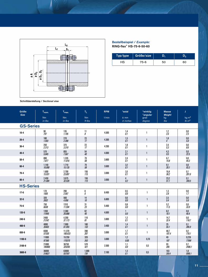
Schnittdarstellung / Sectional view
Typ/type Größe/size D1 D2
HS 75-6 50 60
Bestellbeispiel / Example:RING-flex® HS-75-6-50-60
Größe A D1; D2 D3 D4 LF S1 L0 Größe Tnom. Tmax. TL RPM ∆axial ∆winklig Masse J Size max. Size ∆angular Weight
mm mm mm mm mm mm mm Nm Nm Nm 1/min ± mm grad kg kg m2
inches inches inches inches inches inches inches in-lbs in-lbs ft-lbs ± inches degree lbs lb in2
GS-Series GS-Series 10-4 81
3.19 32 1.3
45,00 1.80 / 50
1.97 6,9 0.27
106,9 4.2 10-4 90
797 135 1.195
11 8 4.500 1,4
0.1 1 1,2 2.6
0,0 2.5
20-4 93 3.66
35 1.38
50,00 2.00 / 55
2.17 8,1 0.32
118,1 4.7 20-4 180
1.593 270 2.390
23 17 4.300 1,5
0.1 1 1,8 4
0,0 5.0
30-4 104 4.09
41 1.6
61,00 2.40 / 55
2.17 8,6 0.34
118,6 4.7 30-4 250
2.213 375 3.319
23 17 4.200 1,8
0.1 1 2,4 5.3
0,0 8.6
40-4 126 4.96
48 1.9
70,00 2.80 / 65
2.56 12,2 0.48
142,2 5.6 40-4 570
5.045 855 7.567
54 40 4.000 2,1
0.1 1 4,3 9.5
0,0 22.5
50-4 143 5.63
54 2.1
81,00 3.20 / 70
2.76 12,7 0.50
152,7 6.0 50-4 890
7.877 1.335 11.816
79 58 3.800 2,4
0.1 1 6,7 14.8
0,0 44.3
60-4 168 6.61
75 3.0
105,00 4.10 / 75
2.95 14,1 0.56
164,2 6.5 60-4 1.140
10.090 1.710 15.135
79 58 3.600 3,2
0.1 1 9,1 20.1
0,0 93.3
70-4 194 7.64
70 2.8
118,00 5.00 / 90
3.54 15,5 0.61
196 7.7 70-4 1.800
15.931 2.700 23.897
156 115 3.000 3,5
0.1 1 16,4 36.2
0,1 201.6
80-4 214 8.43
110 4.3
136,00 5.00 / 110
4.33 20,6 0.81
240,6 9.5 80-4 2.450
21.684 3.675 32.526
156 115 3.000 4
0.2 1 23,2 51.1
0,1 349.5
HS-Series HS-Series 17-6 70,5
2.78 35 1.4
47,00 2.00
10 0.39
39,5 1.56
7,5 0.30
86,5 3.4 17-6 170
1505 290 2.567
8 6 8.400 0,5
0.0 1 1,3 2.8
0,0 1.7
32-6 88 3.46
45 1.8
63,00 2.00
14 0.55
45 1.77
8,8 0.35
98,8 3.9 32-6 320
2832 560 4.956
14 10 6.800 0,6
0.0 1 2,5 5.4
0,0 5.6
75-6 116,5 4.59
60 2.4
81,00 3.00
15 0.59
55 2.17
10,4 0.41
120,4 4.7 75-6 750
6638 1310 11.594
31 23 5.400 0,8
0.0 1 5,2 11.5
0,0 33.9
135-6 140,5 5.53
70 2.8
94,00 4.00
19 0.75
60 2.36
12 0.47
132 5.2 135-6 1350
11949 2.360 20.888
62 46 4.600 1
0.0 1 8,2 18.1
0,0 46.4
240-6 166,5 6.56
90 3.5
115,00 4.50
25 0.98
75 2.95
13 0.51
163 6.4 240-6 2400
21242 4.200 37.173
110 81 3.800 1,2
0.1 1 14,7 32.4
0,0 118.7
400-6 198,5 7.81
100 3.9
136,00 5.00
30 1.18
90 3.54
15 0.59
195 7.7 400-6 4000
35403 7.000 61.955
180 133 3.400 1,4
0.1 1 25 55.1
0,1 285.9
650-6 238 9.37
120 4.7
169,00 7.00
36 1.42
125 4.92
20,8 0.82
270,8 10.7 650-6 6500
57530 11.370 100.633
280 207 3.000 1,7
0.1 1 48,7 107.4
0,2 778.1
1100-6 238 120 169,00 36
1.42 125 22,2 272,2
1100-6 11000 19.250 320
3.000 1,2
0,70 49 0,228
9.37 4.7 6.65 4.92 0.87 10.72 97360 170370 263 0.05 107 778W
2100-8 295 11.61
150 5.9
205,00 8.00
49 1.93
160 6.30
28 1.10
348 13.7 2100-8 21000
185866 36750 325265
570 421 2.500 1,1
0.0 0,5 93 205
0,7 2406.1
3600-8 345 13.58
180 7.1
254,00 10.00
59 2.32
200 7.87
32,2 1.27
432,2 17.0 3600-8 36000
318627 63000 557597
1.000 739 2.100 1,3
0.1 0,5 163 359.4
1,8 5995.1
11
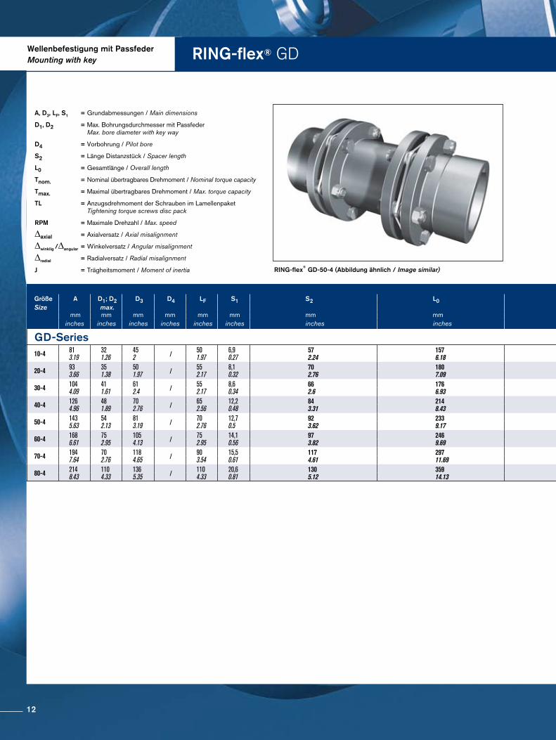
RING-flex® GD
RING-flex® GD-50-4 (Abbildung ähnlich / Image similar)
A, D3, LF, S1 = Grundabmessungen / Main dimensions
D1, D2 = Max. Bohrungsdurchmesser mit Passfeder Max. bore diameter with key way
D4 = Vorbohrung / Pilot bore
S2 = Länge Distanzstück / Spacer length
L0 = Gesamtlänge / Overall length
Tnom. = Nominal übertragbares Drehmoment / Nominal torque capacity
Tmax. = Maximal übertragbares Drehmoment / Max. torque capacity
TL = Anzugsdrehmoment der Schrauben im Lamellenpaket Tightening torque screws disc pack
RPM = Maximale Drehzahl / Max. speed
∆axial = Axialversatz / Axial misalignment
∆winklig /∆angular = Winkelversatz / Angular misalignment
∆radial = Radialversatz / Radial misalignment
J = Trägheitsmoment / Moment of inertia
Wellenbefestigung mit PassfederMounting with key
Größe A D1; D2 D3 D4 LF S1 S2 L0 Größe Tnom. Tmax. TL RPM ∆axial ∆winklig ∆radial Masse JSize max. ∆angular Weight
mm mm mm mm mm mm mm mm Size N m Nm Nm 1/min ± mm grad mm kg kg m2
inches inches inches inches inches inches inches inches in-lbs in-lbs ft-lbs ± inches degree inches lbs lb in2
GD-Series GD-Series10-4 81
3.19321.26
452 / 50
1.976,90.27
572.24
1576.18 10-4 90
7971351195
118 4500 2,7
0.11 2 0,50.02
24.4
0,00124.07
20-4 933.66
351.38
501.97 / 55
2.178,10.32
702.76
1807.09 20-4 180
15932702390
2317 4300 3
0.12 2 0,60.02
3,16.8
0,00258.4
30-4 1044.09
411.61
612.4 / 55
2.178,60.34
662.6
1766.93 30-4 250
22133753319
2317 4200 3,7
0.15 2 0,50.02
48.8
0,004214.2
40-4 1264.96
481.89
702.76 / 65
2.5612,20.48
843.31
2148.43 40-4 570
50458557567
5440 4000 4,2
0.17 2 0,70.03
7,316.1
0,01138.4
50-4 1435.63
542.13
813.19 / 70
2.7612,70.5
923.62
2339.17 50-4 890
7877133511816
7958 3800 4,9
0.19 2 0,90.04
11,625.6
0,02276.4
60-4 1686.61
752.95
1054.13 / 75
2.9514,10.56
973.82
2469.69 60-4 1140
10090171015135
7958 3600 6,4
0.25 2 0,90.04
14,131.1
0,046155.5
70-4 1947.64
702.76
1184.65 / 90
3.5415,50.61
1174.61
29711.69 70-4 1800
15931270023897
156115 3000 6,9
0.27 2 1,70.07
25,656.4
0,98333.9
80-4 2148.43
1104.33
1365.35 / 110
4.3320,60.81
1305.12
35914.13 80-4 2450
21684367532526
156115 3000 8
0.31 2 1,80.07
35,878.9
0,167569.4
12
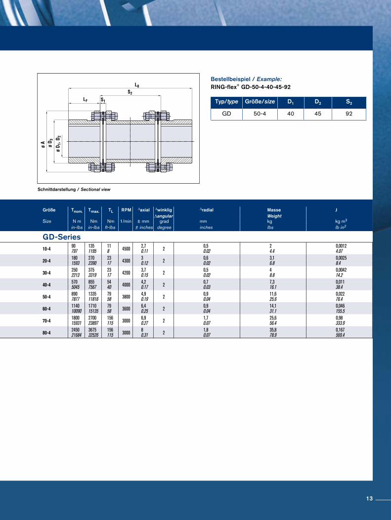
Schnittdarstellung / Sectional view
Typ/type Größe/size D1 D2 S2
GD 50-4 40 45 92
Bestellbeispiel / Example:RING-flex® GD-50-4-40-45-92
Größe A D1; D2 D3 D4 LF S1 S2 L0 Größe Tnom. Tmax. TL RPM ∆axial ∆winklig ∆radial Masse JSize max. ∆angular Weight
mm mm mm mm mm mm mm mm Size N m Nm Nm 1/min ± mm grad mm kg kg m2
inches inches inches inches inches inches inches inches in-lbs in-lbs ft-lbs ± inches degree inches lbs lb in2
GD-Series GD-Series10-4 81
3.19321.26
452 / 50
1.976,90.27
572.24
1576.18 10-4 90
7971351195
118 4500 2,7
0.11 2 0,50.02
24.4
0,00124.07
20-4 933.66
351.38
501.97 / 55
2.178,10.32
702.76
1807.09 20-4 180
15932702390
2317 4300 3
0.12 2 0,60.02
3,16.8
0,00258.4
30-4 1044.09
411.61
612.4 / 55
2.178,60.34
662.6
1766.93 30-4 250
22133753319
2317 4200 3,7
0.15 2 0,50.02
48.8
0,004214.2
40-4 1264.96
481.89
702.76 / 65
2.5612,20.48
843.31
2148.43 40-4 570
50458557567
5440 4000 4,2
0.17 2 0,70.03
7,316.1
0,01138.4
50-4 1435.63
542.13
813.19 / 70
2.7612,70.5
923.62
2339.17 50-4 890
7877133511816
7958 3800 4,9
0.19 2 0,90.04
11,625.6
0,02276.4
60-4 1686.61
752.95
1054.13 / 75
2.9514,10.56
973.82
2469.69 60-4 1140
10090171015135
7958 3600 6,4
0.25 2 0,90.04
14,131.1
0,046155.5
70-4 1947.64
702.76
1184.65 / 90
3.5415,50.61
1174.61
29711.69 70-4 1800
15931270023897
156115 3000 6,9
0.27 2 1,70.07
25,656.4
0,98333.9
80-4 2148.43
1104.33
1365.35 / 110
4.3320,60.81
1305.12
35914.13 80-4 2450
21684367532526
156115 3000 8
0.31 2 1,80.07
35,878.9
0,167569.4
13
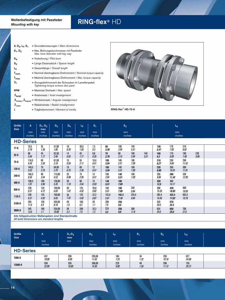
RING-flex® HDWellenbefestigung mit PassfederMounting with key
RING-flex® HD-75-6
A, D3, LF, S1 = Grundabmessungen / Main dimensions
D1, D2 = Max. Bohrungsdurchmesser mit Passfeder Max. bore diameter with key way
D4 = Vorbohrung / Pilot bore
S2 = Länge Distanzstück / Spacer length
L0 = Gesamtlänge / Overall length
Tnom. = Nominal übertragbares Drehmoment / Nominal torque capacity
Tmax. = Maximal übertragbares Drehmoment / Max. torque capacity
TL = Anzugsdrehmoment der Schrauben im Lamellenpaket Tightening torque screws disc pack
RPM = Maximale Drehzahl / Max. speed
∆axial = Axialversatz / Axial misalignment
∆winklig /∆angular = Winkelversatz / Angular misalignment
∆radial = Radialversatz / Radial misalignment
J = Trägheitsmoment / Moment of inertia
Größe A D1:D2 D3 LF S1 S2 LO Größe Tnom. Tmax. TL RPM RPM ∆axial ∆angular ∆radial Masse JSize max Size 1/min 1/min weight
mm mm mm mm mm mm mm Nm Nm Nm unsymmetrisch symmetrisch +/- mm grad mm kg kg-m2
inches inches inches inches inches inches lb-in lb-in lb-ft unbalanced balanced +/- inches degrees inches lbs lb-in2
HD-Series HD-Series7200-8 457
18.002008.00
295,0011.63
1847.25
341.32
25910.18
62724.68 7200-8 72300
6400001446001280000
21701600 3500 5900 3,0
0.12 0,33 1,20.05
245540
6,44122009
13500-8 55922.00
25010.00
368,0014.50
2299.00
401.56
29811.72
75529.72 13500-8 135600
12000002600002300000
36602700 3100 4800 3,6
0.14 0,33 1,40.05
446984
17,69060443
HD-Series HD-Series17-6 70,5
2.78351.38
47,001.85
100.39
39,51.56
7,50.3
602,36
1003.94
1405.51
1395,47
1797.05
2198.62 17-6 170
15052902567
86 8400 1,1
0.04 2 0,8 0.03
1,5 0.05
2,2 0.06
1,543.4
1,663.7
1,793.9
0,00082.60
0,00082.77
0,00092.97
32-6 883.46
451.77
62,502.46
140.55
451.77
8,80.35
702,76
803.15
1003.94
1405.51
1606,3
1706.69
1907.48
2309.06 32-6 320
28325604956
1410 6800 1,2
0.05 2 1,0 0.03
1,1 0.04
1,5 0.05
2,1 0.07
3,16.8
3,156.9
3,267.2
3,487.7
0,00258.61
0,00268.75
0,00269.05
0,00289.64
75-6 116,54.59
602.36
81,003.19
150.59
552.17
10,40.41
1003,94
1405.51
1807.09
2108,27
2509.84
29011.42 75-6 750
6638131011594
31223 5400 1,6
0.06 2 1,4 0.05
2,1 0.07
2,8 0.09
6,5514.4
6,8515.1
7,1415.7
0,009331.71
0,009933.69
0,01035.77
135-6 140,55.53
702.76
94,003.70
190.75
602.36
120.47
1003,94
1405.51
1807.09
2208,66
26010.24
30011.81 135-6 1350
11949236020888
6246 4600 2,1
0.08 2 1,5 0.04
2,1 0.07
2,8 0.09
10,2922.7
10,7223.6
11,1624.6
0,02171.52
0,02274.45
0,02377.36
240-6 166,56.56
903.54
115,004.53
250.98
752.95
130.51
1003.94
1405,51
1807.09
2509.84
29011,42
33012.99 240-6 2400
21242420037173
11081 3800 2,5
0.1 2 1,4 0.04
2,1 0.07
2,8 0.09
17,8139.3
18,540.8
19,1942.3
0,052176.82
0,054183.79
0,056190.8
400-6 198,57.81
1003.94
136,005.35
301.18
903.54
150.59
1405,51
1807,09
32012,6
36014.17 400-6 4000
35403700061955
180133 3400 2,8
0.11 2 2,0 0.06
2,7 0.09
30,1666.5
30,9268.2
0,124424.14
0,127435.18
650-6 2389.37
1204.72
169,006.65
361.42
1254.92
20,80.82
1405.51
1807,09
250 39015.35
43016,93
500650-6 6500
5753011370100633
280207 3000 3,4
0.13 2 2,0 0.08
2,6 0.10
3,8 0.15
58,65129.3
60,5133.4
62 137
0,3341141.89
0,3461181.01
0,360 12309.84 19.69
1100-6 238 125 169,00 361.42
125 22,2 142,4 182,4 252,4 392,4 432,4 502,41100-6
11000 19250 3203000
1,21,4
1,6 2,1 2,70 59 60 62 0,3341142
0,3461181
0,36012309.37 4.92 6.65 4.92 0.87 5.61 7,18 9.94 15.45 17,02 19.78 97360 170370 236 0.05 0.06 0.08 0.11 129 133 137
2100-8 29511.6
1505.9
205,008.10
491.9
1606.3
281.1
2007.9
2509,8
52020.5
57022,4 2100-8 21000
185866 36750325265
570421 2500 2,2
0.1 1 20.1
2,50.1
58,7129.3
60,5133.4
1,0683648.1
1,0993753.6
3600-8 34513.6
1807.1
254,0010.00
592.3
2007.9
32,21.3
224 2509,8
30011.8
62424.6
65025,6
70027.6 3600-8 36000
31862763000557597
1000739 2100
2,51 2
0.12,50.1
30.1
205,3452.7
207,3457
211,1465.3
2,6158935.4
2,6369006.2
2,6769142.18.8 0.1
Alle fettgedruckten Maßangaben sind Standardmaße All bold dimensions are standard lengths
Größe A D1; D2 D3 D4 LF S1 S2 L0 Größe Tnom. Tmax. TL RPM ∆axial ∆winklig ∆radial Masse JSize max. ∆angular Weight
mm mm mm mm mm mm mm mm Size N m Nm Nm 1/min ± mm grad mm kg kg m2
inches inches inches inches inches inches inches inches in-lbs in-lbs ft-lbs ± inches degree inches lbs lb in2
14
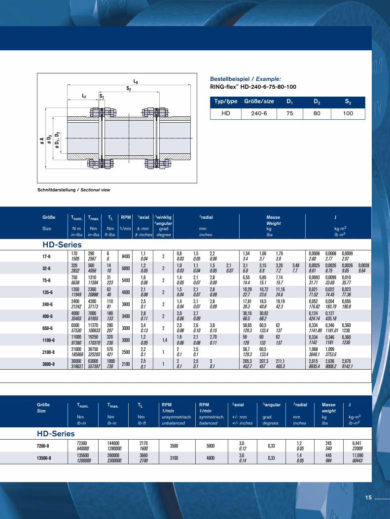
Schnittdarstellung / Sectional view
Größe A D1:D2 D3 LF S1 S2 LO Größe Tnom. Tmax. TL RPM RPM ∆axial ∆angular ∆radial Masse JSize max Size 1/min 1/min weight
mm mm mm mm mm mm mm Nm Nm Nm unsymmetrisch symmetrisch +/- mm grad mm kg kg-m2
inches inches inches inches inches inches lb-in lb-in lb-ft unbalanced balanced +/- inches degrees inches lbs lb-in2
HD-Series HD-Series7200-8 457
18.002008.00
295,0011.63
1847.25
341.32
25910.18
62724.68 7200-8 72300
6400001446001280000
21701600 3500 5900 3,0
0.12 0,33 1,20.05
245540
6,44122009
13500-8 55922.00
25010.00
368,0014.50
2299.00
401.56
29811.72
75529.72 13500-8 135600
12000002600002300000
36602700 3100 4800 3,6
0.14 0,33 1,40.05
446984
17,69060443
HD-Series HD-Series17-6 70,5
2.78351.38
47,001.85
100.39
39,51.56
7,50.3
602,36
1003.94
1405.51
1395,47
1797.05
2198.62 17-6 170
15052902567
86 8400 1,1
0.04 2 0,8 0.03
1,5 0.05
2,2 0.06
1,543.4
1,663.7
1,793.9
0,00082.60
0,00082.77
0,00092.97
32-6 883.46
451.77
62,502.46
140.55
451.77
8,80.35
702,76
803.15
1003.94
1405.51
1606,3
1706.69
1907.48
2309.06 32-6 320
28325604956
1410 6800 1,2
0.05 2 1,0 0.03
1,1 0.04
1,5 0.05
2,1 0.07
3,16.8
3,156.9
3,267.2
3,487.7
0,00258.61
0,00268.75
0,00269.05
0,00289.64
75-6 116,54.59
602.36
81,003.19
150.59
552.17
10,40.41
1003,94
1405.51
1807.09
2108,27
2509.84
29011.42 75-6 750
6638131011594
31223 5400 1,6
0.06 2 1,4 0.05
2,1 0.07
2,8 0.09
6,5514.4
6,8515.1
7,1415.7
0,009331.71
0,009933.69
0,01035.77
135-6 140,55.53
702.76
94,003.70
190.75
602.36
120.47
1003,94
1405.51
1807.09
2208,66
26010.24
30011.81 135-6 1350
11949236020888
6246 4600 2,1
0.08 2 1,5 0.04
2,1 0.07
2,8 0.09
10,2922.7
10,7223.6
11,1624.6
0,02171.52
0,02274.45
0,02377.36
240-6 166,56.56
903.54
115,004.53
250.98
752.95
130.51
1003.94
1405,51
1807.09
2509.84
29011,42
33012.99 240-6 2400
21242420037173
11081 3800 2,5
0.1 2 1,4 0.04
2,1 0.07
2,8 0.09
17,8139.3
18,540.8
19,1942.3
0,052176.82
0,054183.79
0,056190.8
400-6 198,57.81
1003.94
136,005.35
301.18
903.54
150.59
1405,51
1807,09
32012,6
36014.17 400-6 4000
35403700061955
180133 3400 2,8
0.11 2 2,0 0.06
2,7 0.09
30,1666.5
30,9268.2
0,124424.14
0,127435.18
650-6 2389.37
1204.72
169,006.65
361.42
1254.92
20,80.82
1405.51
1807,09
250 39015.35
43016,93
500650-6 6500
5753011370100633
280207 3000 3,4
0.13 2 2,0 0.08
2,6 0.10
3,8 0.15
58,65129.3
60,5133.4
62 137
0,3341141.89
0,3461181.01
0,360 12309.84 19.69
1100-6 238 125 169,00 361.42
125 22,2 142,4 182,4 252,4 392,4 432,4 502,41100-6
11000 19250 3203000
1,21,4
1,6 2,1 2,70 59 60 62 0,3341142
0,3461181
0,36012309.37 4.92 6.65 4.92 0.87 5.61 7,18 9.94 15.45 17,02 19.78 97360 170370 236 0.05 0.06 0.08 0.11 129 133 137
2100-8 29511.6
1505.9
205,008.10
491.9
1606.3
281.1
2007.9
2509,8
52020.5
57022,4 2100-8 21000
185866 36750325265
570421 2500 2,2
0.1 1 20.1
2,50.1
58,7129.3
60,5133.4
1,0683648.1
1,0993753.6
3600-8 34513.6
1807.1
254,0010.00
592.3
2007.9
32,21.3
224 2509,8
30011.8
62424.6
65025,6
70027.6 3600-8 36000
31862763000557597
1000739 2100
2,51 2
0.12,50.1
30.1
205,3452.7
207,3457
211,1465.3
2,6158935.4
2,6369006.2
2,6769142.18.8 0.1
Alle fettgedruckten Maßangaben sind Standardmaße All bold dimensions are standard lengths
Größe A D1; D2 D3 D4 LF S1 S2 L0 Größe Tnom. Tmax. TL RPM ∆axial ∆winklig ∆radial Masse JSize max. ∆angular Weight
mm mm mm mm mm mm mm mm Size N m Nm Nm 1/min ± mm grad mm kg kg m2
inches inches inches inches inches inches inches inches in-lbs in-lbs ft-lbs ± inches degree inches lbs lb in2
Typ/type Größe/size D1 D2 S2
HD 240-6 75 80 100
Bestellbeispiel / Example:RING-flex® HD-240-6-75-80-100
15
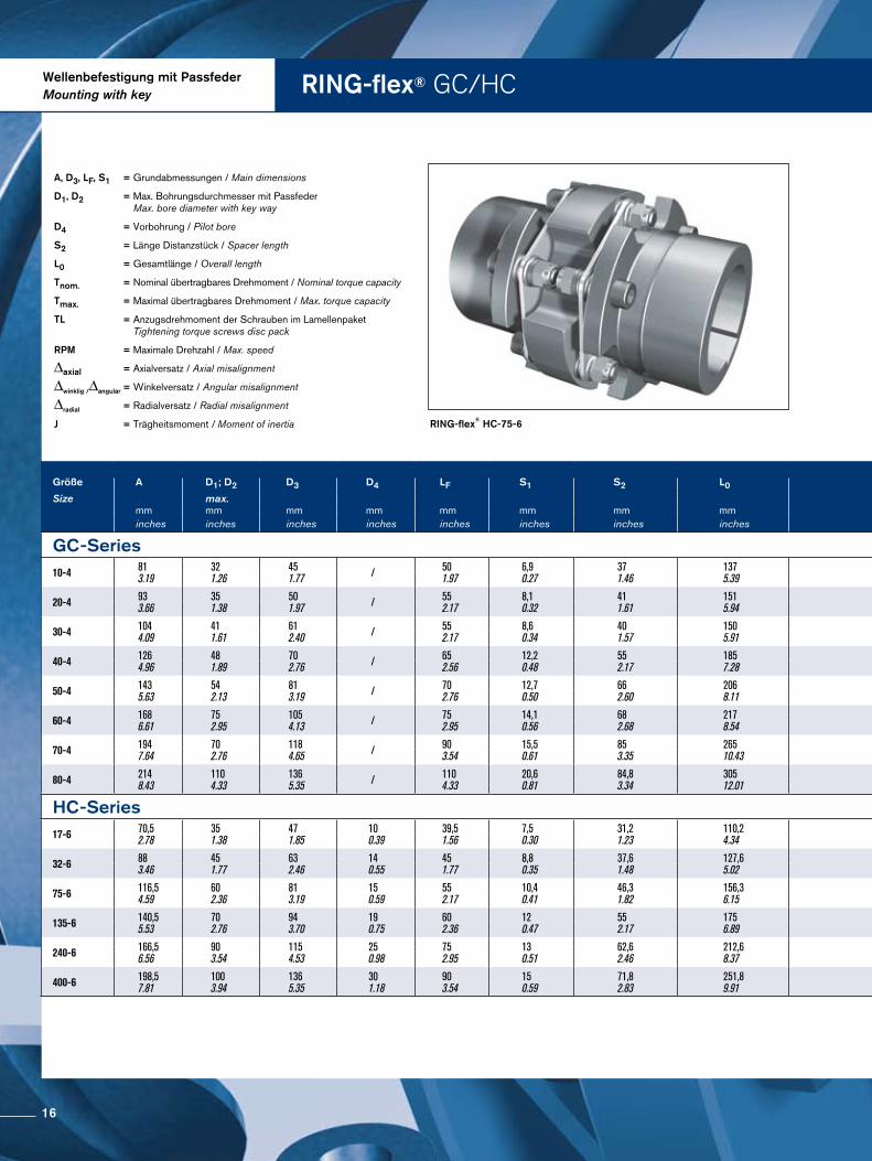
RING-flex® GC/HCWellenbefestigung mit PassfederMounting with key
RING-flex® HC-75-6
A, D3, LF, S1 = Grundabmessungen / Main dimensions
D1, D2 = Max. Bohrungsdurchmesser mit Passfeder Max. bore diameter with key way
D4 = Vorbohrung / Pilot bore
S2 = Länge Distanzstück / Spacer length
L0 = Gesamtlänge / Overall length
Tnom. = Nominal übertragbares Drehmoment / Nominal torque capacity
Tmax. = Maximal übertragbares Drehmoment / Max. torque capacity
TL = Anzugsdrehmoment der Schrauben im Lamellenpaket Tightening torque screws disc pack
RPM = Maximale Drehzahl / Max. speed
∆axial = Axialversatz / Axial misalignment
∆winklig /∆angular = Winkelversatz / Angular misalignment
∆radial = Radialversatz / Radial misalignment
J = Trägheitsmoment / Moment of inertia
Größe A D1; D2 D3 D4 LF S1 S2 L0 Größe T nom. Tmax. TL RPM ∆axial ∆winklig ∆radial Masse J
Size max. Size ∆angular Weight mm mm mm mm mm mm mm mm Nm Nm Nm 1/min ± mm grad mm kg kg m2
inches inches inches inches inches inches inches inches in-lbs in-lbs ft-lbs ± inches degree inches lbs lb in2
GC-Series GC-Series10-4 81
3.19 32 1.26
45 1.77 / 50
1.97 6,9 0.27
37 1.46
137 5.39 10-4 90
797 135 1195
11 8 4500 2,7
0.11 2 0,5 0.02
1,5 3.3
0,0008 2.82
20-4 93 3.66
35 1.38
50 1.97 / 55
2.17 8,1 0.32
41 1.61
151 5.94 20-4 180
1593 270 2390
23 17 4300 3
0.12 2 0,5 0.02
2,2 4.9
0,0017 5.94
30-4 104 4.09
41 1.61
61 2.40 / 55
2.17 8,6 0.34
40 1.57
150 5.91 30-4 250
2213 375 3319
23 17 4200 3,7
0.15 2 0,5 0.02
2,9 6.4
0,0029 10.00
40-4 126 4.96
48 1.89
70 2.76 / 65
2.56 12,2 0.48
55 2.17
185 7.28 40-4 570
5045 855 7567
54 40 4000 4,2
0.17 2 0,8 0.03
5,4 11.9
0,00781 26.70
50-4 143 5.63
54 2.13
81 3.19 / 70
2.76 12,7 0.50
66 2.60
206 8.11 50-4 890
7877 1335 11816
79 58 3800 4,9
0.19 2 1 0.04
8,1 17.9
0,016 52.80
60-4 168
6.61 75 2.95
105 4.13 / 75
2.95 14,1 0.56
68 2.68
217 8.54 60-4 1.140
10.090 1710 15135
79 58 3600 6,4
0.25 2 1 0.04
10,8 23.8
0,034 116.10
70-4 194 7.64
70 2.76
118 4.65 / 90
3.54 15,5 0.61
85 3.35
265 10.43 70-4 1.800
15931 2700 23897
156 115 3000 6,9
0.27 2 1,3 0.05
20,7 45.6
0,017 244.00
80-4 214 8.43
110 4.33
136 5.35 / 110
4.33 20,6 0.81
84,8 3.34
305 12.01 80-4 2450
21684 3675 32526
156 115 3000 8
0.31 2 1,3 0.05
28,9 63.7
0,122 416.70
HC-Series HC-Series17-6 70,5
2.78 35 1.38
47 1.85
10 0.39
39,5 1.56
7,5 0.30
31,2 1.23
110,2 4.34 17-6 170
1505 290 2567
8 6 8400 1,1
0.04 2 0,4 0.02
1,48 3.3
0,0007 2.43
32-6 88 3.46
45 1.77
63 2.46
14 0.55
45 1.77
8,8 0.35
37,6 1.48
127,6 5.02 32-6 320
2832 560 4956
14 10 6800 1,2
0.05 2 0,5 0.02
2,89 6.4
0,0022 7.45
75-6 116,5 4.59
60 2.36
81 3.19
15 0.59
55 2.17
10,4 0.41
46,3 1.82
156,3 6.15 75-6 750
6638 1310 11594
31 23 5400 1,6
0.06 2 0,6 0.02
6,0 13.7
0,0080 27.20
135-6 140,5 5.53
70 2.76
94 3.70
19 0.75
60 2.36
12 0.47
55 2.17
175 6.89 135-6 1350
11949 2360 20888
62 46 4600 2,1
0.08 2 0,7 0.03
9,7 21.4
0,018 62.32
240-6 166,5 6.56
90 3.54
115 4.53
25 0.98
75 2.95
13 0.51
62,6 2.46
212,6 8.37 240-6 2400
21242 4200 37173
110 81 3800 2,5
0.10 2 0,8 0.03
17,2 37.9
0,050 170.78
400-6 198,5 7.81
100 3.94
136 5.35
30 1.18
90 3.54
15 0.59
71,8 2.83
251,8 9.91 400-6 4000
35403 7000 61955
180 207 3400 2,8
0.11 2 1,0 0.03
28,9 63.7
0,122 416.28
16
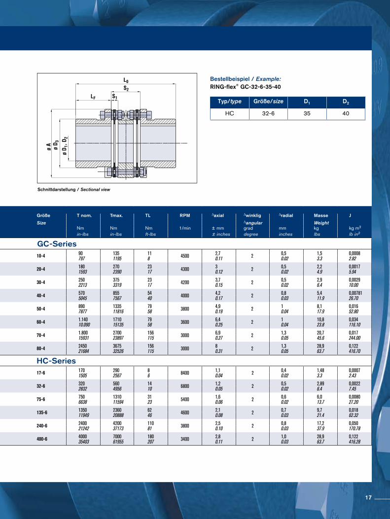
Schnittdarstellung / Sectional view
Bestellbeispiel / Example:RING-flex® GC-32-6-35-40
Typ/type Größe/size D1 D2
HC 32-6 35 40
Größe A D1; D2 D3 D4 LF S1 S2 L0 Größe T nom. Tmax. TL RPM ∆axial ∆winklig ∆radial Masse J
Size max. Size ∆angular Weight mm mm mm mm mm mm mm mm Nm Nm Nm 1/min ± mm grad mm kg kg m2
inches inches inches inches inches inches inches inches in-lbs in-lbs ft-lbs ± inches degree inches lbs lb in2
GC-Series GC-Series10-4 81
3.19 32 1.26
45 1.77 / 50
1.97 6,9 0.27
37 1.46
137 5.39 10-4 90
797 135 1195
11 8 4500 2,7
0.11 2 0,5 0.02
1,5 3.3
0,0008 2.82
20-4 93 3.66
35 1.38
50 1.97 / 55
2.17 8,1 0.32
41 1.61
151 5.94 20-4 180
1593 270 2390
23 17 4300 3
0.12 2 0,5 0.02
2,2 4.9
0,0017 5.94
30-4 104 4.09
41 1.61
61 2.40 / 55
2.17 8,6 0.34
40 1.57
150 5.91 30-4 250
2213 375 3319
23 17 4200 3,7
0.15 2 0,5 0.02
2,9 6.4
0,0029 10.00
40-4 126 4.96
48 1.89
70 2.76 / 65
2.56 12,2 0.48
55 2.17
185 7.28 40-4 570
5045 855 7567
54 40 4000 4,2
0.17 2 0,8 0.03
5,4 11.9
0,00781 26.70
50-4 143 5.63
54 2.13
81 3.19 / 70
2.76 12,7 0.50
66 2.60
206 8.11 50-4 890
7877 1335 11816
79 58 3800 4,9
0.19 2 1 0.04
8,1 17.9
0,016 52.80
60-4 168
6.61 75 2.95
105 4.13 / 75
2.95 14,1 0.56
68 2.68
217 8.54 60-4 1.140
10.090 1710 15135
79 58 3600 6,4
0.25 2 1 0.04
10,8 23.8
0,034 116.10
70-4 194 7.64
70 2.76
118 4.65 / 90
3.54 15,5 0.61
85 3.35
265 10.43 70-4 1.800
15931 2700 23897
156 115 3000 6,9
0.27 2 1,3 0.05
20,7 45.6
0,017 244.00
80-4 214 8.43
110 4.33
136 5.35 / 110
4.33 20,6 0.81
84,8 3.34
305 12.01 80-4 2450
21684 3675 32526
156 115 3000 8
0.31 2 1,3 0.05
28,9 63.7
0,122 416.70
HC-Series HC-Series17-6 70,5
2.78 35 1.38
47 1.85
10 0.39
39,5 1.56
7,5 0.30
31,2 1.23
110,2 4.34 17-6 170
1505 290 2567
8 6 8400 1,1
0.04 2 0,4 0.02
1,48 3.3
0,0007 2.43
32-6 88 3.46
45 1.77
63 2.46
14 0.55
45 1.77
8,8 0.35
37,6 1.48
127,6 5.02 32-6 320
2832 560 4956
14 10 6800 1,2
0.05 2 0,5 0.02
2,89 6.4
0,0022 7.45
75-6 116,5 4.59
60 2.36
81 3.19
15 0.59
55 2.17
10,4 0.41
46,3 1.82
156,3 6.15 75-6 750
6638 1310 11594
31 23 5400 1,6
0.06 2 0,6 0.02
6,0 13.7
0,0080 27.20
135-6 140,5 5.53
70 2.76
94 3.70
19 0.75
60 2.36
12 0.47
55 2.17
175 6.89 135-6 1350
11949 2360 20888
62 46 4600 2,1
0.08 2 0,7 0.03
9,7 21.4
0,018 62.32
240-6 166,5 6.56
90 3.54
115 4.53
25 0.98
75 2.95
13 0.51
62,6 2.46
212,6 8.37 240-6 2400
21242 4200 37173
110 81 3800 2,5
0.10 2 0,8 0.03
17,2 37.9
0,050 170.78
400-6 198,5 7.81
100 3.94
136 5.35
30 1.18
90 3.54
15 0.59
71,8 2.83
251,8 9.91 400-6 4000
35403 7000 61955
180 207 3400 2,8
0.11 2 1,0 0.03
28,9 63.7
0,122 416.28
17
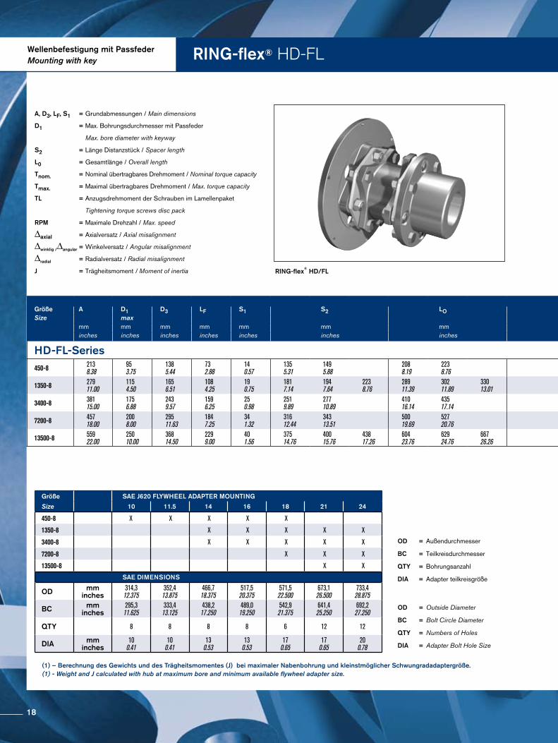
RING-flex® HDFLWellenbefestigung mit PassfederMounting with key
RING-flex® HD/FL
A, D3, LF, S1 = Grundabmessungen / Main dimensions
D1 = Max. Bohrungsdurchmesser mit Passfeder
Max. bore diameter with keyway
S2 = Länge Distanzstück / Spacer length
L0 = Gesamtlänge / Overall length
Tnom. = Nominal übertragbares Drehmoment / Nominal torque capacity
Tmax. = Maximal übertragbares Drehmoment / Max. torque capacity
TL = Anzugsdrehmoment der Schrauben im Lamellenpaket
Tightening torque screws disc pack
RPM = Maximale Drehzahl / Max. speed
∆axial = Axialversatz / Axial misalignment
∆winklig /∆angular = Winkelversatz / Angular misalignment
∆radial = Radialversatz / Radial misalignment
J = Trägheitsmoment / Moment of inertia
Größe A D1 D3 LF S1 S2 LO Größe Tnom. Tmax. TL RPM ∆axial ∆angular ∆radial Masse JSize max Size 1/min weight
mm mm mm mm mm mm mm Nm Nm Nm unsymmetrisch +/- mm grad mm kg kg-m2
inches inches inches inches inches inches inches lb-in lb-in lb-ft unbalanced +/- inches degrees inches lbs lb-in2
HD-FL-Series HD-FL-Series450-8 213
8.38953.75
1385.44
732.88
140.57
1355.31
1495.88
2088.19
2238.76 450-8 4500
40000678060000
150110 3400 1,5
0.06 0,33 0,70.03
0,80.03
2146
2147
0,164561
0,166566
1350-8 27911.00
1154.50
1656.51
1084.25
190.75
1817.14
1947.64
2238.76
28911.39
30211.89
33013.01 1350-8 13500
12000020300180000
490360 2500 2,0
0.08 0,33 0,90.04
1,00.04
1,20.05
58127
58128
60132
0,9433223
0,9473237
0,9563268
3400-8 38115.00
1756.88
2439.57
1596.25
250.98
2519.89
27710.89
41016.14
43517.14 3400-8 27100
24000040600360000
1140840 1800 2,5
0.10 0,33 1,30.05
1,40.06
118260
121267
2,4178258
2,4528378
7200-8 45718.00
2008.00
29511.63
1847.25
341.32
31612.44
34313.51
50019.69
52720.76 7200-8 63200
56000094900840000
21701600 1500 3,0
0.12 0,33 1,60.06
1,80.07
222489
227501
6,53322321
6,61522602
13500-8 55922.00
25010.00
36814.50
2299.00
401.56
37514.76
40015.76
43817.26
60423.76
62924.76
66726.26 13500-8 124200
11000001864001650000
36602700 1200 3,6
0.14 0,33 1,90.08
2,10.08
2,30.09
395871
402887
418922
17,24458922
17,43259563
19,20365615
OD = Outside Diameter
BC = Bolt Circle Diameter
QTY = Numbers of Holes
DIA = Adapter Bolt Hole Size
OD = Außendurchmesser
BC = Teilkreisdurchmesser
QTY = Bohrungsanzahl
DIA = Adapter teilkreisgröße
Größe SAE J620 FLYWHEEL ADAPTER MOUNTING
Size 10 11.5 14 16 18 21 24
450-8 X X X X X
1350-8 X X X X X
3400-8 X X X X X
7200-8 X X X
13500-8 X X
SAE DIMENSIONS
OD mminches
314,312.375
352,413.875
466,718.375
517,520.375
571,522.500
673,126.500
733,428.875
BC mminches
295,311.625
333,413.125
438,217.250
489,019.250
542,921.375
641,425.250
692,227.250
QTY 8 8 8 8 6 12 12
DIA mminches
100.41
100.41
130.53
130.53
170.65
170.65
200.78
(1) – Berechnung des Gewichts und des Trägheitsmomentes (J) bei maximaler Nabenbohrung und kleinstmöglicher Schwungradadaptergröße. (1) - Weight and J calculated with hub at maximum bore and minimum available flywheel adapter size.
18
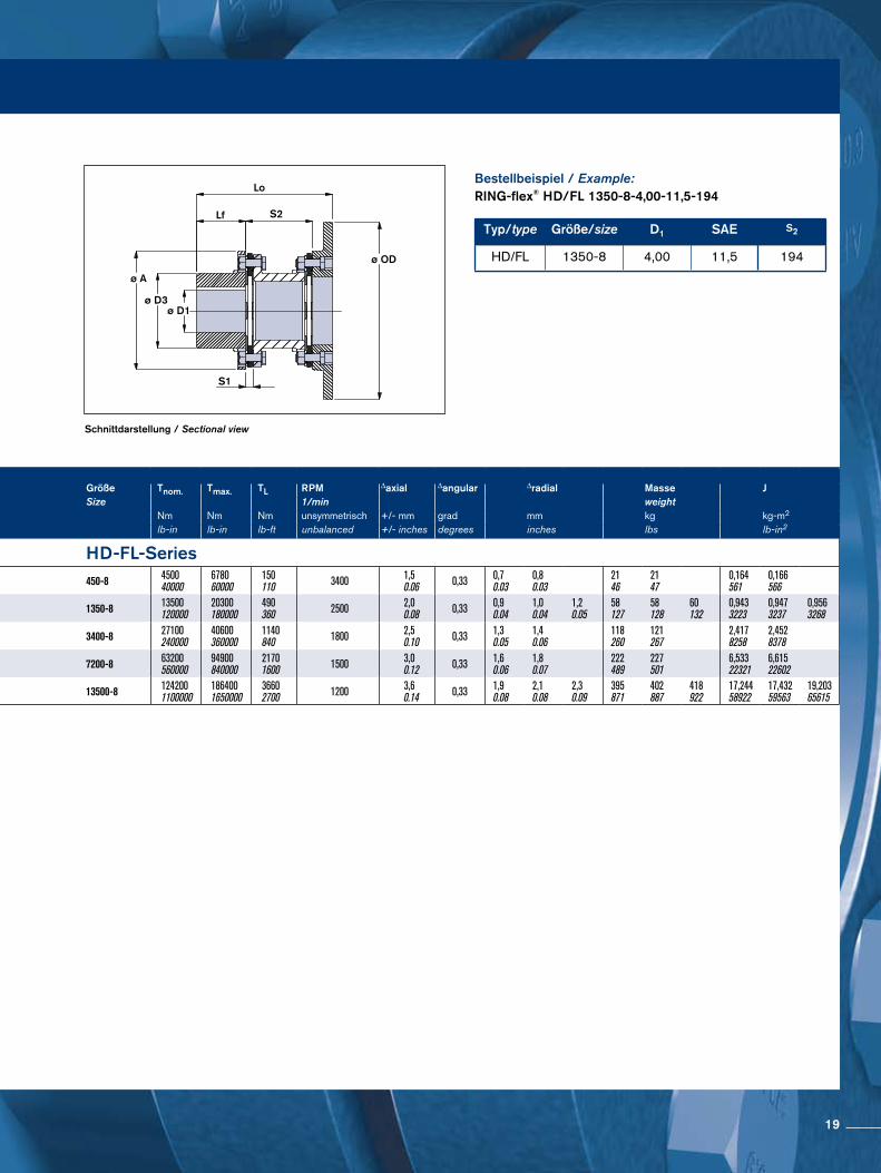
Schnittdarstellung / Sectional view
Bestellbeispiel / Example:RING-flex® HD/FL 1350-8-4,00-11,5-194
Typ/type Größe/size D1 SAE S2
HD/FL 1350-8 4,00 11,5 194
ø A
Lo
Lf S2
ø OD
S1
ø D3ø D1
Größe A D1 D3 LF S1 S2 LO Größe Tnom. Tmax. TL RPM ∆axial ∆angular ∆radial Masse JSize max Size 1/min weight
mm mm mm mm mm mm mm Nm Nm Nm unsymmetrisch +/- mm grad mm kg kg-m2
inches inches inches inches inches inches inches lb-in lb-in lb-ft unbalanced +/- inches degrees inches lbs lb-in2
HD-FL-Series HD-FL-Series450-8 213
8.38953.75
1385.44
732.88
140.57
1355.31
1495.88
2088.19
2238.76 450-8 4500
40000678060000
150110 3400 1,5
0.06 0,33 0,70.03
0,80.03
2146
2147
0,164561
0,166566
1350-8 27911.00
1154.50
1656.51
1084.25
190.75
1817.14
1947.64
2238.76
28911.39
30211.89
33013.01 1350-8 13500
12000020300180000
490360 2500 2,0
0.08 0,33 0,90.04
1,00.04
1,20.05
58127
58128
60132
0,9433223
0,9473237
0,9563268
3400-8 38115.00
1756.88
2439.57
1596.25
250.98
2519.89
27710.89
41016.14
43517.14 3400-8 27100
24000040600360000
1140840 1800 2,5
0.10 0,33 1,30.05
1,40.06
118260
121267
2,4178258
2,4528378
7200-8 45718.00
2008.00
29511.63
1847.25
341.32
31612.44
34313.51
50019.69
52720.76 7200-8 63200
56000094900840000
21701600 1500 3,0
0.12 0,33 1,60.06
1,80.07
222489
227501
6,53322321
6,61522602
13500-8 55922.00
25010.00
36814.50
2299.00
401.56
37514.76
40015.76
43817.26
60423.76
62924.76
66726.26 13500-8 124200
11000001864001650000
36602700 1200 3,6
0.14 0,33 1,90.08
2,10.08
2,30.09
395871
402887
418922
17,24458922
17,43259563
19,20365615
OD = Outside Diameter
BC = Bolt Circle Diameter
QTY = Numbers of Holes
DIA = Adapter Bolt Hole Size
OD = Außendurchmesser
BC = Teilkreisdurchmesser
QTY = Bohrungsanzahl
DIA = Adapter teilkreisgröße
19
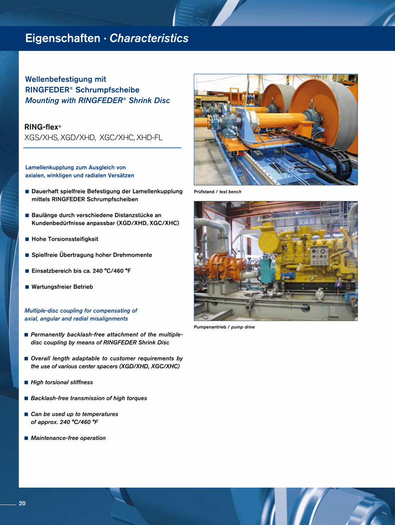
Eigenschaften · Characteristics
Wellenbefestigung mit RINGFEDER® SchrumpfscheibeMounting with RINGFEDER® Shrink Disc
Prüfstand / test bench
Pumpenantrieb / pump drive
Lamellenkupplung zum Ausgleich von axialen, winkligen und radialen Versätzen
Dauerhaft spielfreie Befestigung der Lamellenkupplung mittels RINGFEDER Schrumpfscheiben
Baulänge durch verschiedene Distanzstücke an Kundenbedürfnisse anpassbar (XGD/XHD, XGC/XHC)
Hohe Torsionssteifigkeit
Spielfreie Übertragung hoher Drehmomente
Einsatzbereich bis ca. 240 °C/460 °F
Wartungsfreier Betrieb
Multiple-disc coupling for compensating ofaxial, angular and radial misalignments
Permanently backlash-free attachment of the multiple- disc coupling by means of RINGFEDER Shrink Disc
Overall length adaptable to customer requirements by the use of various center spacers (XGD/XHD, XGC/XHC)
High torsional stiffness
Backlash-free transmission of high torques
Can be used up to temperatures of approx. 240 °C/460 °F
Maintenance-free operation
RING-flex®
XGS/XHS, XGD/XHD, XGC/XHC, XHDFL
20
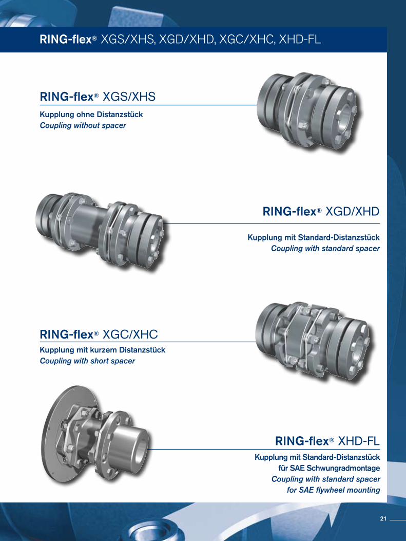
RING-flex® XGS/XHS, XGD/XHD, XGC/XHC, XHDFL
Kupplung mit Standard-Distanzstück für SAE Schwungradmontage
Coupling with standard spacer for SAE flywheel mounting
RING-flex® XHD-FL
Kupplung ohne DistanzstückCoupling without spacer
RING-flex® XGS/XHS
Kupplung mit Standard-DistanzstückCoupling with standard spacer
RING-flex® XGD/XHD
Kupplung mit kurzem Distanzstück Coupling with short spacer
RING-flex® XGC/XHC
21
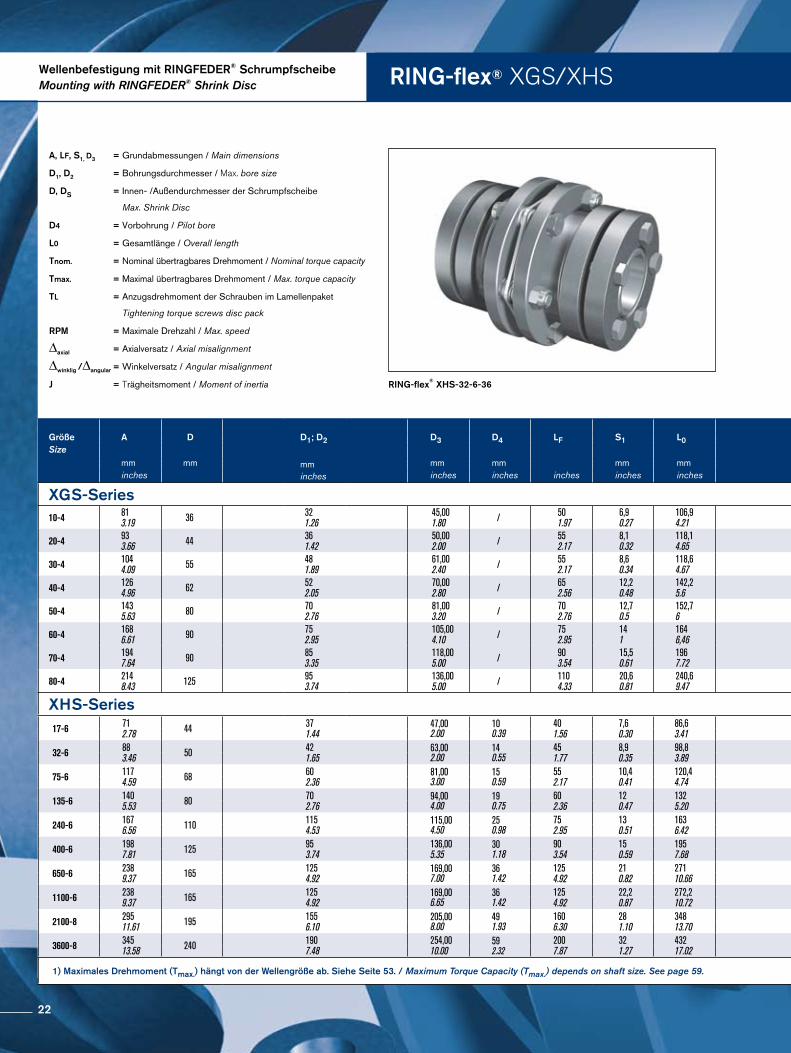
RING-flex® XGS/XHSWellenbefestigung mit RINGFEDER® SchrumpfscheibeMounting with RINGFEDER® Shrink Disc
A, LF, S1, D3 = Grundabmessungen / Main dimensions
D1, D2 = Bohrungsdurchmesser / Max. bore size
D, DS = Innen- /Außendurchmesser der Schrumpfscheibe
Max. Shrink Disc
D4 = Vorbohrung / Pilot bore
L0 = Gesamtlänge / Overall length
Tnom. = Nominal übertragbares Drehmoment / Nominal torque capacity
Tmax. = Maximal übertragbares Drehmoment / Max. torque capacity
TL = Anzugsdrehmoment der Schrauben im Lamellenpaket
Tightening torque screws disc pack
RPM = Maximale Drehzahl / Max. speed
∆axial = Axialversatz / Axial misalignment
∆winklig /∆angular = Winkelversatz / Angular misalignment
J = Trägheitsmoment / Moment of inertia RING-flex® XHS-32-6-36
Größe A D D1; D2
mm inches
D3 D4 LF S1 L0 Größe Tnom. Tmax. TL RPM ∆axial ∆winklig Masse JSize Size (1) ∆angular weight
mm mm mm mm mm mm Nm Nm Nm 1/min ± mm grad kg kg m2
inches inches inches inches inches inches in-lbs in-lbs ft-lbs ± inches degree lbs lb in2
XGS-Series XGS-Series10-4 81
3.19 36 32 1.26
45,00 1.80 / 50
1.97 6,9 0.27
106,9 4.21 10-4 90
797 135 1195
11 8 4500 1,4
0.06 1 1,8 4
0,00139 4.74
20-4 93 3.66 44 36
1.42 50,00 2.00 / 55
2.17 8,1 0.32
118,1 4.65 20-4 180
1.593 270 2390
23 17 4300 1,5
0.06 1 2,8 6.2
0,00260 8.89
30-4 104 4.09 55 48
1.89 61,00 2.40 / 55
2.17 8,6 0.34
118,6 4.67 30-4 250
2.213 375 3319
23 17 4200 1,8
0.07 1 3,9 8.6
0,00574 19.60
40-4 126 4.96 62 52
2.05 70,00 2.80 / 65
2.56 12,2 0.48
142,2 5.6 40-4 570
5.045 855 7567
54 40 4000 2,1
0.08 1 6,1 13.4
0,011112 38.00
50-4 143 5.63 80 70
2.76 81,00 3.20 / 70
2.76 12,7 0.5
152,7 6 50-4 890
7.877 1335 11816
79 58 3800 2,4
0.09 1 10,3 22.7
0,0284 97.20
60-4 168 6.61 90 75
2.95 105,00 4.10 / 75
2.95 14 1
164 6,46 60-4 1.140
10.090 1710 15135
79 58 3600 3,2
0.13 1 14 30.9
0,0502 171.40
70-4 194 7.64 90 85
3.35 118,00 5.00 / 90
3.54 15,5 0.61
196 7.72 70-4 1.800
15.931 2700 23897
156 115 3000 3,5
0.14 1 23 51
0,0768 262.30
80-4 214 8.43 125 95
3.74 136,00 5.00 / 110
4.33 20,6 0.81
240,6 9.47 80-4 2.450
21.684 3675 32526
156 115 3000 4
0.16 1 36 78
0,2219 758.30
XHS-Series XHS-Series17-6 71
2.78 44 371.44
47,002.00
100.39
401.56
7,60.30
86,63.41 17-6 170
15052902567
86 8400 0,5
0.02 1 1,3 2.8
0,00072.46
32-6 883.46 50 42
1.6563,002.00
140.55
451.77
8,90.35
98,83.89 32-6 320
28325604956
1410 6800 0,5
0.02 1 2,4 5.4
0,00155.03
75-6 1174.59 68 60
2.3681,003.00
150.59
552.17
10,40.41
120,44.74 75-6 750
6638131011594
3123 5400 0,8
0.03 1 5,2 11.5
0,01033.9
135-6 1405.53 80 70
2.7694,004.00
190.75
602.36
120.47
1325.20 135-6 1350
11949236020888
6346 4600 1,0
0.04 1 8,2 18.1
0,01446.4
240-6 1676.56 110 115
4.53115,004.50
250.98
752.95
130.51
1636.42 240-6 2400
21242420037173
11081 3800 1,2
0.05 1 15 32
0,035119
400-6 1987.81 125 95
3.74136,005.35
301.18
903.54
150.59
1957.68 400-6 4000
35403700061955
180133 3400 1,4
0.06 1 25 55
0,084286
650-6 2389.37 165 125
4.92169,007.00
361.42
1254.92
210.82
27110.66 650-6 6500
5753011370100633
280207 3000 1,7
0.07 1 49 107
0,228778
1100-6 2389.37 165 125
4.92169,006.65
36 1.42
1254.92
22,20.87
272,210.72 1100-6 11000
9736019250170370
320236 3000 1,2
0.05 0,70 49 107
0,228778
2100-8 29511.61 195 155
6.10205,008.00
491.93
1606.30
281.10
34813.70 2100-8 21000
18586636750325265
570421 2500 1,1
0.04 0,50 93 205
0,7042406
3600-8 34513.58 240 190
7.48254,0010.00
592.32
2007.87
321.27
43217.02 3600-8 36000
31862763000557597
1000739 2100 1,3
0.05 0,50 163 359
1,7555995
1) Maximales Drehmoment (Tmax.) hängt von der Wellengröße ab. Siehe Seite 53. / Maximum Torque Capacity (Tmax.) depends on shaft size. See page 59.
22
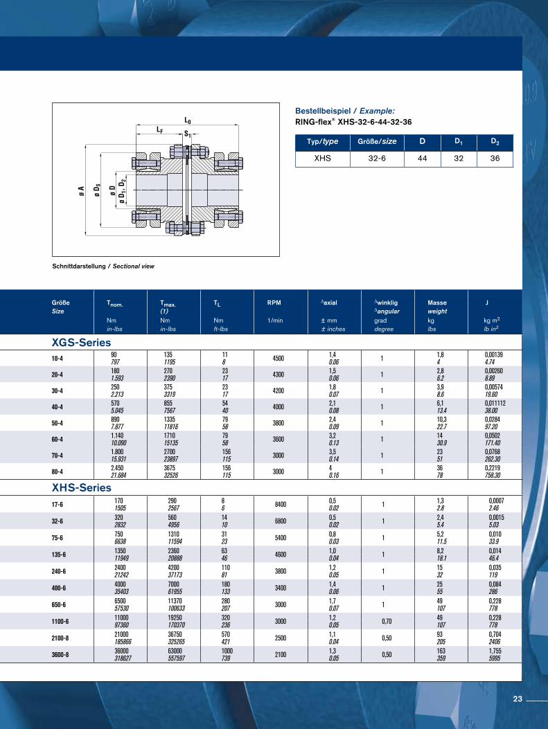
Schnittdarstellung / Sectional view
Bestellbeispiel / Example:RING-flex® XHS-32-6-44-32-36
Typ/type Größe/size D D1 D2
XHS 32-6 44 32 36
Größe A D D1; D2
mm inches
D3 D4 LF S1 L0 Größe Tnom. Tmax. TL RPM ∆axial ∆winklig Masse JSize Size (1) ∆angular weight
mm mm mm mm mm mm Nm Nm Nm 1/min ± mm grad kg kg m2
inches inches inches inches inches inches in-lbs in-lbs ft-lbs ± inches degree lbs lb in2
XGS-Series XGS-Series10-4 81
3.19 36 32 1.26
45,00 1.80 / 50
1.97 6,9 0.27
106,9 4.21 10-4 90
797 135 1195
11 8 4500 1,4
0.06 1 1,8 4
0,00139 4.74
20-4 93 3.66 44 36
1.42 50,00 2.00 / 55
2.17 8,1 0.32
118,1 4.65 20-4 180
1.593 270 2390
23 17 4300 1,5
0.06 1 2,8 6.2
0,00260 8.89
30-4 104 4.09 55 48
1.89 61,00 2.40 / 55
2.17 8,6 0.34
118,6 4.67 30-4 250
2.213 375 3319
23 17 4200 1,8
0.07 1 3,9 8.6
0,00574 19.60
40-4 126 4.96 62 52
2.05 70,00 2.80 / 65
2.56 12,2 0.48
142,2 5.6 40-4 570
5.045 855 7567
54 40 4000 2,1
0.08 1 6,1 13.4
0,011112 38.00
50-4 143 5.63 80 70
2.76 81,00 3.20 / 70
2.76 12,7 0.5
152,7 6 50-4 890
7.877 1335 11816
79 58 3800 2,4
0.09 1 10,3 22.7
0,0284 97.20
60-4 168 6.61 90 75
2.95 105,00 4.10 / 75
2.95 14 1
164 6,46 60-4 1.140
10.090 1710 15135
79 58 3600 3,2
0.13 1 14 30.9
0,0502 171.40
70-4 194 7.64 90 85
3.35 118,00 5.00 / 90
3.54 15,5 0.61
196 7.72 70-4 1.800
15.931 2700 23897
156 115 3000 3,5
0.14 1 23 51
0,0768 262.30
80-4 214 8.43 125 95
3.74 136,00 5.00 / 110
4.33 20,6 0.81
240,6 9.47 80-4 2.450
21.684 3675 32526
156 115 3000 4
0.16 1 36 78
0,2219 758.30
XHS-Series XHS-Series17-6 71
2.78 44 371.44
47,002.00
100.39
401.56
7,60.30
86,63.41 17-6 170
15052902567
86 8400 0,5
0.02 1 1,3 2.8
0,00072.46
32-6 883.46 50 42
1.6563,002.00
140.55
451.77
8,90.35
98,83.89 32-6 320
28325604956
1410 6800 0,5
0.02 1 2,4 5.4
0,00155.03
75-6 1174.59 68 60
2.3681,003.00
150.59
552.17
10,40.41
120,44.74 75-6 750
6638131011594
3123 5400 0,8
0.03 1 5,2 11.5
0,01033.9
135-6 1405.53 80 70
2.7694,004.00
190.75
602.36
120.47
1325.20 135-6 1350
11949236020888
6346 4600 1,0
0.04 1 8,2 18.1
0,01446.4
240-6 1676.56 110 115
4.53115,004.50
250.98
752.95
130.51
1636.42 240-6 2400
21242420037173
11081 3800 1,2
0.05 1 15 32
0,035119
400-6 1987.81 125 95
3.74136,005.35
301.18
903.54
150.59
1957.68 400-6 4000
35403700061955
180133 3400 1,4
0.06 1 25 55
0,084286
650-6 2389.37 165 125
4.92169,007.00
361.42
1254.92
210.82
27110.66 650-6 6500
5753011370100633
280207 3000 1,7
0.07 1 49 107
0,228778
1100-6 2389.37 165 125
4.92169,006.65
36 1.42
1254.92
22,20.87
272,210.72 1100-6 11000
9736019250170370
320236 3000 1,2
0.05 0,70 49 107
0,228778
2100-8 29511.61 195 155
6.10205,008.00
491.93
1606.30
281.10
34813.70 2100-8 21000
18586636750325265
570421 2500 1,1
0.04 0,50 93 205
0,7042406
3600-8 34513.58 240 190
7.48254,0010.00
592.32
2007.87
321.27
43217.02 3600-8 36000
31862763000557597
1000739 2100 1,3
0.05 0,50 163 359
1,7555995
1) Maximales Drehmoment (Tmax.) hängt von der Wellengröße ab. Siehe Seite 53. / Maximum Torque Capacity (Tmax.) depends on shaft size. See page 59.
23
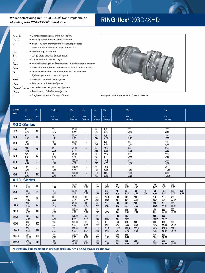
RING-flex® XGD/XHDWellenbefestigung mit RINGFEDER® SchrumpfscheibeMounting with RINGFEDER® Shrink Disc
Beispiel / sample RING-flex® XHD-32-6-36
A, LF, S1 = Grundabmessungen / Main dimensions
D1, D2 = Bohrungsdurchmesser / Bore diameter
D = Innen- /Außendurchmesser der Schrumpfscheibe
Inner and outer diameter of the Shrink Disc
D4 = Vorbohrung / Pilot bore
S2 = Länge Distanzstück / Spacer length
L0 = Gesamtlänge / Overall length
Tnom. = Nominal übertragbares Drehmoment / Nominal torque capacity
Tmax. = Maximal übertragbares Drehmoment / Max. torque capacity
TL = Anzugsdrehmoment der Schrauben im Lamellenpaket
Tightening torque screws disc pack
RPM = Maximale Drehzahl / Max. speed
∆axial = Axialversatz / Axial misalignment
∆winklig /∆angular = Winkelversatz / Angular misalignment
∆radial = Radialversatz / Radial misalignment
J = Trägheitsmoment / Moment of inertia
Größe A D D1; D2 D3 D4 LF S1 S2 L0 Größe Tnom. Tmax. TL RPM. ∆axial ∆winklig ∆radial Masse JSize Size (1) ∆angular Weight
mm mm mm mm mm mm mm mm mm Nm Nm Nm 1/min ± mm grad mm kg kg m2
inches inches inches inches inches inches inches inches in-lbs in-lbs ft-lbs ± inches degree inches lbs lb in2
XGD-Series XGD-Series10-4 81
3.19 36 321.26
45,002.00 / 50
1.976,90.27
572,24
1576,18 10-4 90
7971351195
119 4500 2,7
0.11 2 0,90.0354
2,55.5
0,001866.35
20-4 933.66 44 36
1.4250,001.97 / 55
2.178,10.32
702,76
1807,09 20-4 180
15932702390
2317 4300 3
0.12 2 10.0394
4,19.0
0,0036012.3
30-4 1044.09 55 48
1.8961,002.40 / 55
2.178,60.34
662,60
1766,93 30-4 250
22133753319
2317 4200 3,7
0.15 2 10.0394
5,512.1
0,0073525..1
40-4 1264.96 62 52
2.0570,002.76 / 65
2.5612,20.48
843,31
2148,43 40-4 570
50458557567
5440 4000 4,2
0.17 2 1,20.0472
9,220.3
0,0157753.9
50-4 1435,63 80 70
2,7681,003.19 / 70
2,7612,70,50
923,62
2339,17 50-4 890
7877133511816
7958 3800 4,9
0,19 2 1,20,0472
15,333,7
0,0378129,3
60-4 1686.61 90 75
2.95105,004.13 / 75
2.9514,10.56
973,82
2469,69 60-4 1140
10090171015135
7958 3600 6,4
0.25 2 1,40.0551
19,041.9
0,0684233.6
70-4 1947,64 90 85
3,35118,004.65 / 90
3,5415,50,61
1174,61
29711,69 70-4 1800
15931270023897
156115 3000 6,9
0,27 2 1,70,0669
32,170,8
0,1155394,8
80-4 2148.43 125 95
3.74136,005.35 / 110
4.3320,60.81
1305,12
35013,78 80-4 2450
21684367532526
156115 3000 8
0.31 2 1,80.0709
47,9105.6
0,2863978.3
XHD-Series XHD-Series17-6 71
2.78 44 371.44
47,001.85
10 0.39
40 1.56
7,60.30
602,36
1003.94
1405.51
1395,47
1797.05
2198.62 17-6 170
15052902567
86 8400 1,1
0.04 2 0,80.03
1,50.05
2,20.06
1,53.4
1,73.7
1,83.9
0,00082.60
0,00082.77
0,00092.97
32-6 883.46 50 42
1.6562,002.46
140.55
451.77
8,90.35
702,76
803.15
1003.94
1405.51
1606,30
1706.69
1907.48
2309.06 32-6 320
28325604956
1410 6800 1,2
0.05 2 1,00.03
1,10.04
1,50.05
2,10.07
3,16.8
3,16.9
3,37.2
3,57.7
0,00258.61
0,00268.75
0,00269.05
0,00289.64
75-6 1174.59 68 60
2.3681,003.19
150.59
552.17
10,40.41
1003,94
1405.51
1807.09
2108,27
2509.84
29011.42 75-6 750
6638131011594
3123 5400 1,6
0.06 2 1,40.05
2,10.07
2,80.09
6,514.4
6,815.1
7,115.7
0,00931.7
0,01033.7
0,01035.8
135-6 1405.53 80 70
2.7694,003.70
190.75
602.36
120.47
1003,94
1405.51
1807.09
2208,66
26010.24
30011.81 135-6 1350
11949236020888
6346 4600 2,1
0.08 2 1,50.04
2,10.07
2,80.09
1023
1124
1125
0,02171.5
0,02274.5
0,02377.4
240-6 1676.56 110 115
4.53115,004.53
250.98
752.95
130.51
1003.94
1405,51
1807.09
2509.84
29011,42
33012.99
240-6 2400
21242420037173
11081 3800 2,5
0.10 2 1,40.04
2,10.07
2,80.09
1839
1941
1942
0,052176.8
0,054183.8
0,056190.1
400-6 1987.81 125 95
3.74136,005.35
301.18
903.54
150.59
1405,51
1807.09
32012,60
36014,17 400-6 4000
35403700061955
180133 3400 2,8
0.11 2 2,00.06
2,70.09
3067
3168
0,124424.1
0,127435.2
650-6 2389.37 165 125
4.92169,006.65
361.42
1254.92
210.82
1405.51
1807,09
2509.84
39015.35
43016,93
50019.69
650-6 6500
5753011370100633
280207 3000 3,4
0.13 2 2,00.08
2,60.10
3,80.15
59129
60133
62137
0,3341142
0,3461181
0,3601230
1100-6 2389.37 165 125
4.92169,006.65
36 1,42
1254.92
22,20.87
142,45.61
182,47,18
252,49.94
392,415.45
432,417,02
502,419.78 1100-6 11000
9736019250170370
320236 3000 1,2
0.05 1,4 1,60.06
2,10.08
2,700.11
59129
60133
62137
0,3341142
0,3461181
0,3601230
2100-8 29511.61 195 155
6.10205,008.07
491.93
1606.30
281.10
2007.87
2509,84
52020.47
57022,44 2100-8 21000
18586636750325265
570421 2500 2,2
0.09 1 1,40.06
1,80.07
113249
116256
1,0683648
1,0993754
3600-8 34513.58 240 190
7.48254,0010.00
592.32
2007.87
321.27
2248.82
2509,84
30011.81
62424.57
65025,59
70027.56
3600-8 36000
31862763000557597
1000739 2100 2,5
0.1 1 1,60.06
1,80.07
2,20.09
205453
207457
211465
2,6158935
2,6369006
2,6769142
Alle fettgedruckten Maßangaben sind Standardmaße. / All bold dimensions are standard 1) Maximales Drehmoment (Tmax) kann durch Wellengröße begrenzt werden. Siehe Seite 43. / Maximum Torque Capacity (Tmax) may be limiited shaft size. See page 43.
24
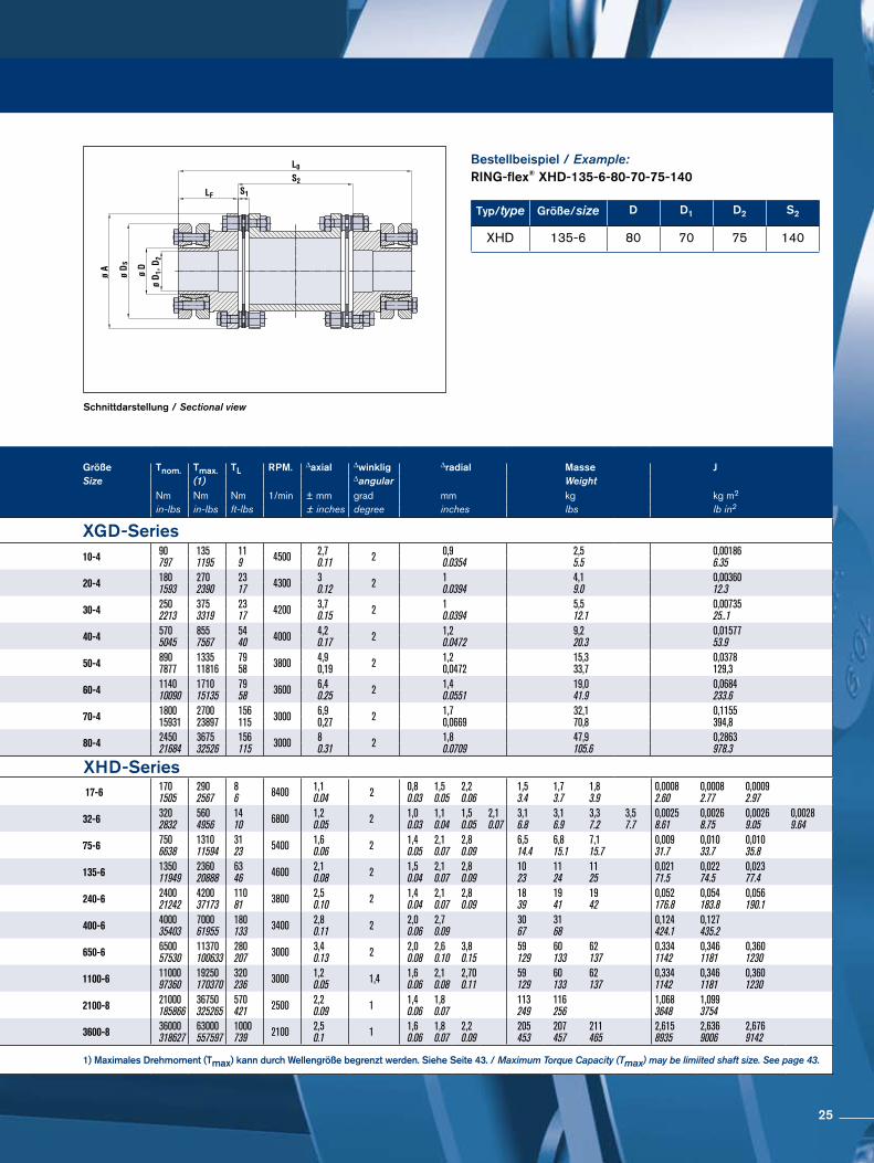
Schnittdarstellung / Sectional view
Bestellbeispiel / Example:RING-flex® XHD-135-6-80-70-75-140
Typ/type Größe/size D D1 D2 S2
XHD 135-6 80 70 75 140
Größe A D D1; D2 D3 D4 LF S1 S2 L0 Größe Tnom. Tmax. TL RPM. ∆axial ∆winklig ∆radial Masse JSize Size (1) ∆angular Weight
mm mm mm mm mm mm mm mm mm Nm Nm Nm 1/min ± mm grad mm kg kg m2
inches inches inches inches inches inches inches inches in-lbs in-lbs ft-lbs ± inches degree inches lbs lb in2
XGD-Series XGD-Series10-4 81
3.19 36 321.26
45,002.00 / 50
1.976,90.27
572,24
1576,18 10-4 90
7971351195
119 4500 2,7
0.11 2 0,90.0354
2,55.5
0,001866.35
20-4 933.66 44 36
1.4250,001.97 / 55
2.178,10.32
702,76
1807,09 20-4 180
15932702390
2317 4300 3
0.12 2 10.0394
4,19.0
0,0036012.3
30-4 1044.09 55 48
1.8961,002.40 / 55
2.178,60.34
662,60
1766,93 30-4 250
22133753319
2317 4200 3,7
0.15 2 10.0394
5,512.1
0,0073525..1
40-4 1264.96 62 52
2.0570,002.76 / 65
2.5612,20.48
843,31
2148,43 40-4 570
50458557567
5440 4000 4,2
0.17 2 1,20.0472
9,220.3
0,0157753.9
50-4 1435,63 80 70
2,7681,003.19 / 70
2,7612,70,50
923,62
2339,17 50-4 890
7877133511816
7958 3800 4,9
0,19 2 1,20,0472
15,333,7
0,0378129,3
60-4 1686.61 90 75
2.95105,004.13 / 75
2.9514,10.56
973,82
2469,69 60-4 1140
10090171015135
7958 3600 6,4
0.25 2 1,40.0551
19,041.9
0,0684233.6
70-4 1947,64 90 85
3,35118,004.65 / 90
3,5415,50,61
1174,61
29711,69 70-4 1800
15931270023897
156115 3000 6,9
0,27 2 1,70,0669
32,170,8
0,1155394,8
80-4 2148.43 125 95
3.74136,005.35 / 110
4.3320,60.81
1305,12
35013,78 80-4 2450
21684367532526
156115 3000 8
0.31 2 1,80.0709
47,9105.6
0,2863978.3
XHD-Series XHD-Series17-6 71
2.78 44 371.44
47,001.85
10 0.39
40 1.56
7,60.30
602,36
1003.94
1405.51
1395,47
1797.05
2198.62 17-6 170
15052902567
86 8400 1,1
0.04 2 0,80.03
1,50.05
2,20.06
1,53.4
1,73.7
1,83.9
0,00082.60
0,00082.77
0,00092.97
32-6 883.46 50 42
1.6562,002.46
140.55
451.77
8,90.35
702,76
803.15
1003.94
1405.51
1606,30
1706.69
1907.48
2309.06 32-6 320
28325604956
1410 6800 1,2
0.05 2 1,00.03
1,10.04
1,50.05
2,10.07
3,16.8
3,16.9
3,37.2
3,57.7
0,00258.61
0,00268.75
0,00269.05
0,00289.64
75-6 1174.59 68 60
2.3681,003.19
150.59
552.17
10,40.41
1003,94
1405.51
1807.09
2108,27
2509.84
29011.42 75-6 750
6638131011594
3123 5400 1,6
0.06 2 1,40.05
2,10.07
2,80.09
6,514.4
6,815.1
7,115.7
0,00931.7
0,01033.7
0,01035.8
135-6 1405.53 80 70
2.7694,003.70
190.75
602.36
120.47
1003,94
1405.51
1807.09
2208,66
26010.24
30011.81 135-6 1350
11949236020888
6346 4600 2,1
0.08 2 1,50.04
2,10.07
2,80.09
1023
1124
1125
0,02171.5
0,02274.5
0,02377.4
240-6 1676.56 110 115
4.53115,004.53
250.98
752.95
130.51
1003.94
1405,51
1807.09
2509.84
29011,42
33012.99
240-6 2400
21242420037173
11081 3800 2,5
0.10 2 1,40.04
2,10.07
2,80.09
1839
1941
1942
0,052176.8
0,054183.8
0,056190.1
400-6 1987.81 125 95
3.74136,005.35
301.18
903.54
150.59
1405,51
1807.09
32012,60
36014,17 400-6 4000
35403700061955
180133 3400 2,8
0.11 2 2,00.06
2,70.09
3067
3168
0,124424.1
0,127435.2
650-6 2389.37 165 125
4.92169,006.65
361.42
1254.92
210.82
1405.51
1807,09
2509.84
39015.35
43016,93
50019.69
650-6 6500
5753011370100633
280207 3000 3,4
0.13 2 2,00.08
2,60.10
3,80.15
59129
60133
62137
0,3341142
0,3461181
0,3601230
1100-6 2389.37 165 125
4.92169,006.65
36 1,42
1254.92
22,20.87
142,45.61
182,47,18
252,49.94
392,415.45
432,417,02
502,419.78 1100-6 11000
9736019250170370
320236 3000 1,2
0.05 1,4 1,60.06
2,10.08
2,700.11
59129
60133
62137
0,3341142
0,3461181
0,3601230
2100-8 29511.61 195 155
6.10205,008.07
491.93
1606.30
281.10
2007.87
2509,84
52020.47
57022,44 2100-8 21000
18586636750325265
570421 2500 2,2
0.09 1 1,40.06
1,80.07
113249
116256
1,0683648
1,0993754
3600-8 34513.58 240 190
7.48254,0010.00
592.32
2007.87
321.27
2248.82
2509,84
30011.81
62424.57
65025,59
70027.56
3600-8 36000
31862763000557597
1000739 2100 2,5
0.1 1 1,60.06
1,80.07
2,20.09
205453
207457
211465
2,6158935
2,6369006
2,6769142
Alle fettgedruckten Maßangaben sind Standardmaße. / All bold dimensions are standard 1) Maximales Drehmoment (Tmax) kann durch Wellengröße begrenzt werden. Siehe Seite 43. / Maximum Torque Capacity (Tmax) may be limiited shaft size. See page 43.
25
RING-flex® XGC/XHCWellenbefestigung mit RINGFEDER® SchrumpfscheibeMounting with RINGFEDER® Shrink Disc
RING-flex® XHC-32-6-36
A, LF, S1 = Grundabmessungen / Main dimensions
D1, D2 = Bohrungsdurchmesser / Bore diameter
D, DS = Innen- /Außendurchmesser der Schrumpfscheibe
Inner and outer diameter of the Shrink Disc
D4 = Vorbohrung / Pilot bore
S2 = Länge Distanzstück / Spacer length
L0 = Gesamtlänge / Overall length
Tnom. = Nominal übertragbares Drehmoment / Nominal torque capacity
Tmax. = Maximal übertragbares Drehmoment / Max. torque capacity
TL = Anzugsdrehmoment der Schrauben im Lamellenpaket
Tightening torque screws disc pack
RPM = Maximale Drehzahl / Max. speed∆
axial = Axialversatz / Axial misalignment∆
winklig /∆angular = Winkelversatz / Angular misalignment∆
radial = Radialversatz / Radial misalignment
J = Trägheitsmoment / Moment of inertia
Größe A D D1; D2 D3 D4 LF S1 S2 L0 Größe Tnom. Tmax. TL RPM. ∆axial ∆winklig ∆radial Masse J
Size Size 1) ∆angular Weightmm mm mm mm mm mm mm mm mm Nm Nm Nm 1/min ± mm grad mm kg kg m2
inches inches inches inches inches inches inches inches in-lbs in-lbs ft-lbs ± inches degree inches lbs lb in2
XGC-Series XGC-Series10-4 81
3.19 36 321.26
45 1.77 / 50
1.976,90.27
371.46
1375.39 10-4 90
7971351195
118 4500 2,7
0.11 2 0,50.020
24.4
0,001495.10
20-4 933.66 44 36
1.42501.97 / 55
2.178,10.32
411.61
1515.94 20-4 180
15932702390
2317 4300 3
0.12 2 0,50.020
3,37.3
0,002879.80
30-4 1044.09 55 48
1.89612.40 / 55
2.178,60.34
401.57
1505.91 30-4 250
22133753319
2317 4200 3,7
0.15 2 0,50.020
4,19
0,0047416.20
40-4 1264.96 62 52
2.05702.76 / 65
2.5612,20.48
552.17
1857.28 40-4 570
50458557567
5440 4000 4,2
0.17 2 0,80.032
7,215.9
0,0123542.20
50-4 1435.63 80 70
2.7681 3.19 / 70
2.7612,70.5
662.6
2068.11 50-4 890
7877133511816
7958 3800 4,9
0.19 2 10.039
9,420.7
0,020068.30
60-4 1686.61 90 75
2.951054.13 / 75
2.9514,10.56
682.68
2178.54 60-4 1140
10090171015135
7958 3600 6,4
0.25 2 10.039
14,732.4
0,0474161.90
70-4 1947.64 90 85
3.351184.65 / 90
3.5415,50.61
853.35
26510.43 70-4 1800
15931270023897
156115 3000 6,9
0.27 2 1,30.051
27,159.7
0,0891304.60
80-4 2148.43 125 95
3.741365.35 / 110
4.3320,60.81
84,83.34
30512.01 80-4 2450
21684367532526
156115 3000 8
0.31 2 1,30.051
4190.4
0,1911652.80
XHC-Series XHC-Series17-6 71
2.78 44 371.44
471.85
10 0.39
401.56
7,60.30
31,21.23
110,24.34 17-6 170
15052902567
86 8400 1,1
0.04 2 0,30.01
1,53.3
0,00072.43
32-6 883.46 50 42
1.65622.46
14 0.55
451.77
8,90.35
37,61.48
127,65.02 32-6 320
28325604956
1410 6800 1,2
0.05 2 0,40.02
2,96.4
0,00227.45
75-6 1174.59 68 60
2.36813.19
15 0.59
552.17
10,40.41
46,31.82
156,36.15 75-6 750
6638131011594
3123 5400 1,6
0.06 2 0,50.02
6,213.7
0,00827.2
135-6 1405.53 80 70
2.76943.70
19 0.75
602.36
120.47
55,12.17
1756.89 135-6 1350
11949236020888
6346 4600 2,1
0.08 2 0,70.03
9,721.4
0,01862.3
240-6 1676.56 110 115
4.531154.53
25 0.98
752.95
130.51
62,52.46
212,68.37 240-6 2400
21242420037173
11081 3800 2,5
0.10 2 0,70.03
1738
0,050171
400-6 1987.81 125 95
3.741365.35
30 1.18
903.54
150.59
71,92.83
251,79.91 400-6 4000
35403700061955
180133 3400 2,8
0.11 2 0,70.03
2964
0,122416
1) Maximales Drehmoment (Tmax.) kann durch Wellengröße begrenzt werden. Siehe Seite 43. Maximum Torque Capacity (Tmax) may be limited by shaft size. See page 43.
26
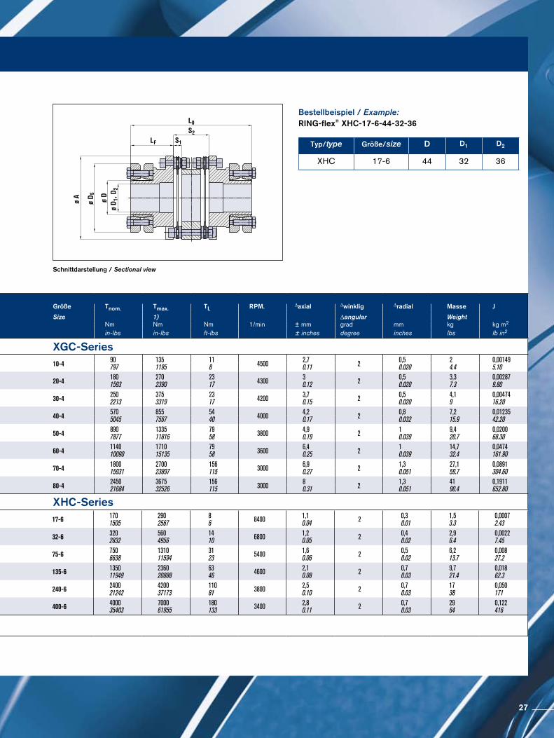
Schnittdarstellung / Sectional view
Bestellbeispiel / Example:RING-flex® XHC-17-6-44-32-36
Typ/type Größe/size D D1 D2
XHC 17-6 44 32 36
Größe A D D1; D2 D3 D4 LF S1 S2 L0 Größe Tnom. Tmax. TL RPM. ∆axial ∆winklig ∆radial Masse J
Size Size 1) ∆angular Weightmm mm mm mm mm mm mm mm mm Nm Nm Nm 1/min ± mm grad mm kg kg m2
inches inches inches inches inches inches inches inches in-lbs in-lbs ft-lbs ± inches degree inches lbs lb in2
XGC-Series XGC-Series10-4 81
3.19 36 321.26
45 1.77 / 50
1.976,90.27
371.46
1375.39 10-4 90
7971351195
118 4500 2,7
0.11 2 0,50.020
24.4
0,001495.10
20-4 933.66 44 36
1.42501.97 / 55
2.178,10.32
411.61
1515.94 20-4 180
15932702390
2317 4300 3
0.12 2 0,50.020
3,37.3
0,002879.80
30-4 1044.09 55 48
1.89612.40 / 55
2.178,60.34
401.57
1505.91 30-4 250
22133753319
2317 4200 3,7
0.15 2 0,50.020
4,19
0,0047416.20
40-4 1264.96 62 52
2.05702.76 / 65
2.5612,20.48
552.17
1857.28 40-4 570
50458557567
5440 4000 4,2
0.17 2 0,80.032
7,215.9
0,0123542.20
50-4 1435.63 80 70
2.7681 3.19 / 70
2.7612,70.5
662.6
2068.11 50-4 890
7877133511816
7958 3800 4,9
0.19 2 10.039
9,420.7
0,020068.30
60-4 1686.61 90 75
2.951054.13 / 75
2.9514,10.56
682.68
2178.54 60-4 1140
10090171015135
7958 3600 6,4
0.25 2 10.039
14,732.4
0,0474161.90
70-4 1947.64 90 85
3.351184.65 / 90
3.5415,50.61
853.35
26510.43 70-4 1800
15931270023897
156115 3000 6,9
0.27 2 1,30.051
27,159.7
0,0891304.60
80-4 2148.43 125 95
3.741365.35 / 110
4.3320,60.81
84,83.34
30512.01 80-4 2450
21684367532526
156115 3000 8
0.31 2 1,30.051
4190.4
0,1911652.80
XHC-Series XHC-Series17-6 71
2.78 44 371.44
471.85
10 0.39
401.56
7,60.30
31,21.23
110,24.34 17-6 170
15052902567
86 8400 1,1
0.04 2 0,30.01
1,53.3
0,00072.43
32-6 883.46 50 42
1.65622.46
14 0.55
451.77
8,90.35
37,61.48
127,65.02 32-6 320
28325604956
1410 6800 1,2
0.05 2 0,40.02
2,96.4
0,00227.45
75-6 1174.59 68 60
2.36813.19
15 0.59
552.17
10,40.41
46,31.82
156,36.15 75-6 750
6638131011594
3123 5400 1,6
0.06 2 0,50.02
6,213.7
0,00827.2
135-6 1405.53 80 70
2.76943.70
19 0.75
602.36
120.47
55,12.17
1756.89 135-6 1350
11949236020888
6346 4600 2,1
0.08 2 0,70.03
9,721.4
0,01862.3
240-6 1676.56 110 115
4.531154.53
25 0.98
752.95
130.51
62,52.46
212,68.37 240-6 2400
21242420037173
11081 3800 2,5
0.10 2 0,70.03
1738
0,050171
400-6 1987.81 125 95
3.741365.35
30 1.18
903.54
150.59
71,92.83
251,79.91 400-6 4000
35403700061955
180133 3400 2,8
0.11 2 0,70.03
2964
0,122416
1) Maximales Drehmoment (Tmax.) kann durch Wellengröße begrenzt werden. Siehe Seite 43. Maximum Torque Capacity (Tmax) may be limited by shaft size. See page 43.
27
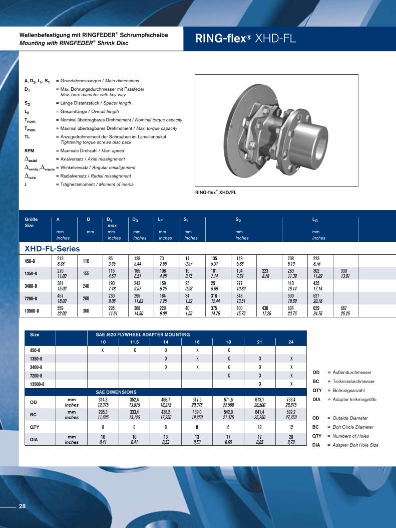
RING-flex® XHDFLWellenbefestigung mit RINGFEDER® SchrumpfscheibeMounting with RINGFEDER® Shrink Disc
RING-flex® XHD/FL
A, D3, LF, S1 = Grundabmessungen / Main dimensions
D1 = Max. Bohrungsdurchmesser mit Passfeder Max. bore diameter with key way
S2 = Länge Distanzstück / Spacer length
L0 = Gesamtlänge / Overall length
Tnom. = Nominal übertragbares Drehmoment / Nominal torque capacity
Tmax. = Maximal übertragbares Drehmoment / Max. torque capacity
TL = Anzugsdrehmoment der Schrauben im Lamellenpaket Tightening torque screws disc pack
RPM = Maximale Drehzahl / Max. speed
∆axial = Axialversatz / Axial misalignment
∆winklig /∆angular = Winkelversatz / Angular misalignment
∆radial = Radialversatz / Radial misalignment
J = Trägheitsmoment / Moment of inertia
Größe A D D1 D3 LF S1 S2 LO Größe Tnom. Tmax. TL RPM ∆axial ∆angular ∆radial Masse JSize max Size (2) 1/min weight (1) (1)
mm mm mm mm mm mm mm mm Nm Nm Nm unsymmetrisch +/- mm grad mm kg kg-m2
inches inches inches inches inches inches inches lb-in lb-in lb-ft unbalanced +/- inches degrees inches lbs lb-in2
XHD-FL-Series XHD-FL-Series450-8 213
8.38 110 853.35
1385.44
732.88
140.57
1355.31
1495.88
2088.19
2238.76 450-8 4500
40000678060000
150110 3400 1,5
0.06 0,33 0,70.03
0,80.03
2146
2147
0,164561
0,166566
1350-8 27911.00 155 115
4.531656.51
1084.25
190.75
1817.14
1947.64
2238.76
28911.39
30211.89
33013.01 1350-8 13500
12000020300180000
490360 2500 2,0
0.08 0,33 0,90.04
1,00.04
1,20.05
58127
58128
60132
0,9433223
0,9473237
0,9563268
3400-8 38115.00 240 190
7.482439.57
1596.25
250.98
2519.89
27710.89
41016.14
43517.14 3400-8 27100
24000040600360000
1140840 1800 2,5
0.10 0,33 1,30.05
1,40.06
118260
121267
2,4178258
2,4528378
7200-8 45718.00 280 230
9.0629511.63
1847.25
341.32
31612.44
34313.51
50019.69
52720.76 7200-8 63200
56000094900840000
21701600 1500 3,0
0.12 0,33 1,60.06
1,80.07
222489
227501
6,53322321
6,61522602
13500-8 55922.00 360 295
11.6136814.50
2299.00
401.56
37514.76
40015.76
43817.26
60423.76
62924.76
66726.26 13500-8 124200
11000001864001650000
36602700 1200 3,6
0.14 0,33 1,90.08
2,10.08
2,30.09
395871
402887
418922
17,24458922
17,43259563
19,20365615
OD = Outside Diameter
BC = Bolt Circle Diameter
QTY = Numbers of Holes
DIA = Adapter Bolt Hole Size
Size SAE J620 FLYWHEEL ADAPTER MOUNTING
10 11.5 14 16 18 21 24
450-8 X X X X X
1350-8 X X X X X
3400-8 X X X X X
7200-8 X X X
13500-8 X X
SAE DIMENSIONS
OD mminches
314,312,375
352,413,875
466,718,375
517,520,375
571,522,500
673,126,500
733,428,875
BC mminches
295,311,625
333,413,125
438,217,250
489,019,250
542,921,375
641,425,250
692,227,250
QTY 8 8 8 8 6 12 12
DIA mminches
100,41
100,41
130,53
130,53
170,65
170,65
200,78
OD = Außendurchmesser
BC = Teilkreisdurchmesser
QTY = Bohrungsanzahl
DIA = Adapter teilkreisgröße
28
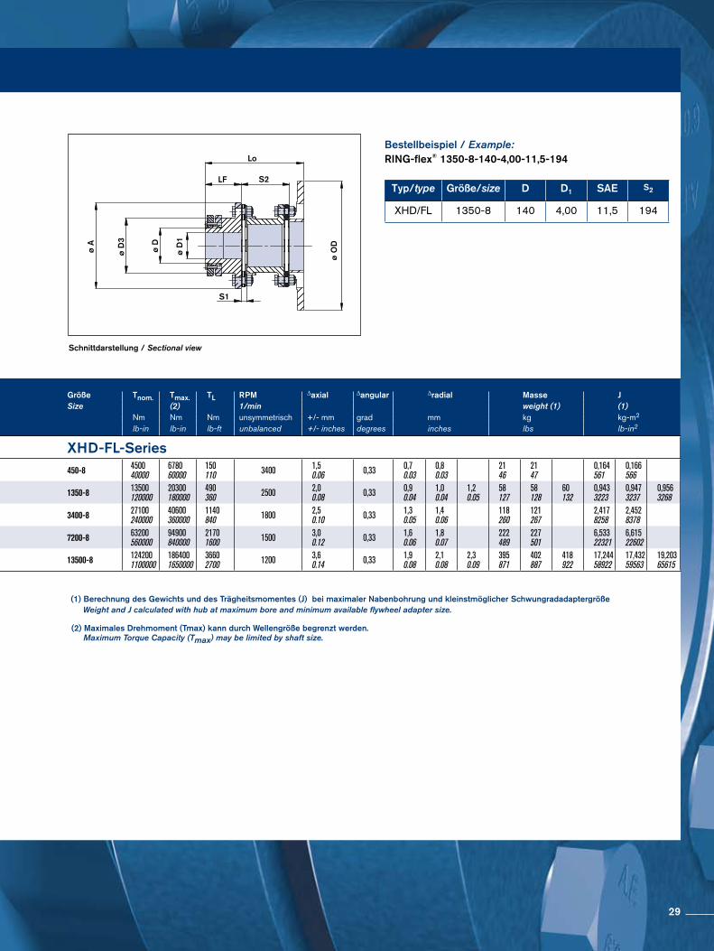
Schnittdarstellung / Sectional view
Bestellbeispiel / Example:RING-flex® 1350-8-140-4,00-11,5-194
ø A
ø D
3
ø D
ø D
1
S1
ø O
D
Lo
LF S2
Größe A D D1 D3 LF S1 S2 LO Größe Tnom. Tmax. TL RPM ∆axial ∆angular ∆radial Masse JSize max Size (2) 1/min weight (1) (1)
mm mm mm mm mm mm mm mm Nm Nm Nm unsymmetrisch +/- mm grad mm kg kg-m2
inches inches inches inches inches inches inches lb-in lb-in lb-ft unbalanced +/- inches degrees inches lbs lb-in2
XHD-FL-Series XHD-FL-Series450-8 213
8.38 110 853.35
1385.44
732.88
140.57
1355.31
1495.88
2088.19
2238.76 450-8 4500
40000678060000
150110 3400 1,5
0.06 0,33 0,70.03
0,80.03
2146
2147
0,164561
0,166566
1350-8 27911.00 155 115
4.531656.51
1084.25
190.75
1817.14
1947.64
2238.76
28911.39
30211.89
33013.01 1350-8 13500
12000020300180000
490360 2500 2,0
0.08 0,33 0,90.04
1,00.04
1,20.05
58127
58128
60132
0,9433223
0,9473237
0,9563268
3400-8 38115.00 240 190
7.482439.57
1596.25
250.98
2519.89
27710.89
41016.14
43517.14 3400-8 27100
24000040600360000
1140840 1800 2,5
0.10 0,33 1,30.05
1,40.06
118260
121267
2,4178258
2,4528378
7200-8 45718.00 280 230
9.0629511.63
1847.25
341.32
31612.44
34313.51
50019.69
52720.76 7200-8 63200
56000094900840000
21701600 1500 3,0
0.12 0,33 1,60.06
1,80.07
222489
227501
6,53322321
6,61522602
13500-8 55922.00 360 295
11.6136814.50
2299.00
401.56
37514.76
40015.76
43817.26
60423.76
62924.76
66726.26 13500-8 124200
11000001864001650000
36602700 1200 3,6
0.14 0,33 1,90.08
2,10.08
2,30.09
395871
402887
418922
17,24458922
17,43259563
19,20365615
OD = Outside Diameter
BC = Bolt Circle Diameter
QTY = Numbers of Holes
DIA = Adapter Bolt Hole Size
(1) Berechnung des Gewichts und des Trägheitsmomentes (J) bei maximaler Nabenbohrung und kleinstmöglicher Schwungradadaptergröße Weight and J calculated with hub at maximum bore and minimum available flywheel adapter size.
Typ/type Größe/size D D1 SAE S2
XHD/FL 1350-8 140 4,00 11,5 194
OD = Außendurchmesser
BC = Teilkreisdurchmesser
QTY = Bohrungsanzahl
DIA = Adapter teilkreisgröße
(2) Maximales Drehmoment (Tmax) kann durch Wellengröße begrenzt werden. Maximum Torque Capacity (Tmax) may be limited by shaft size.
29
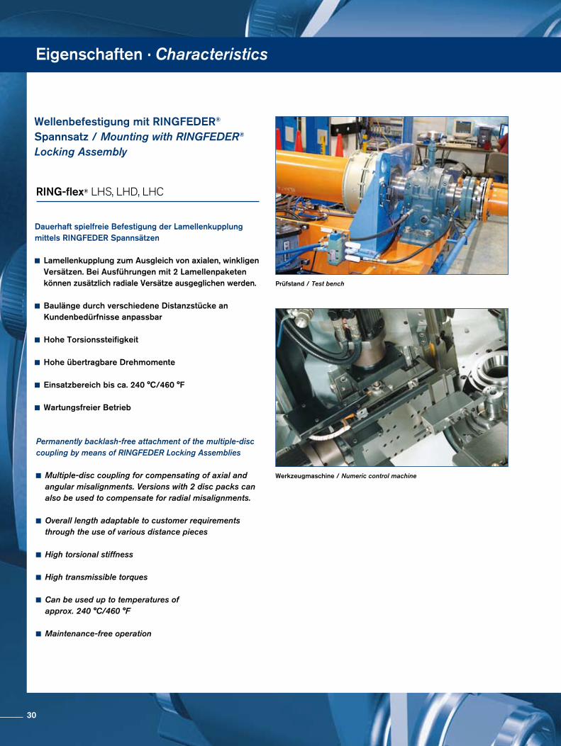
Eigenschaften · Characteristics
Werkzeugmaschine / Numeric control machine
Prüfstand / Test bench
Dauerhaft spielfreie Befestigung der Lamellenkupplung mittels RINGFEDER Spannsätzen
Lamellenkupplung zum Ausgleich von axialen, winkligen Versätzen. Bei Ausführungen mit 2 Lamellen paketen können zusätzlich radiale Versätze ausgeglichen werden.
Baulänge durch verschiedene Distanzstücke an Kundenbedürfnisse anpassbar
Hohe Torsionssteifigkeit
Hohe übertragbare Drehmomente
Einsatzbereich bis ca. 240 °C/460 °F
Wartungsfreier Betrieb
Permanently backlash-free attachment of the multiple-disc coupling by means of RINGFEDER Locking Assemblies
Multiple-disc coupling for compensating of axial and angular misalignments. Versions with 2 disc packs can also be used to compensate for radial misalignments.
Overall length adaptable to customer requirements through the use of various distance pieces
High torsional stiffness
High transmissible torques
Can be used up to temperatures of approx. 240 °C/460 °F
Maintenance-free operation
Wellenbefestigung mit RINGFEDER® Spannsatz / Mounting with RINGFEDER® Locking Assembly
RING-flex® LHS, LHD, LHC
30
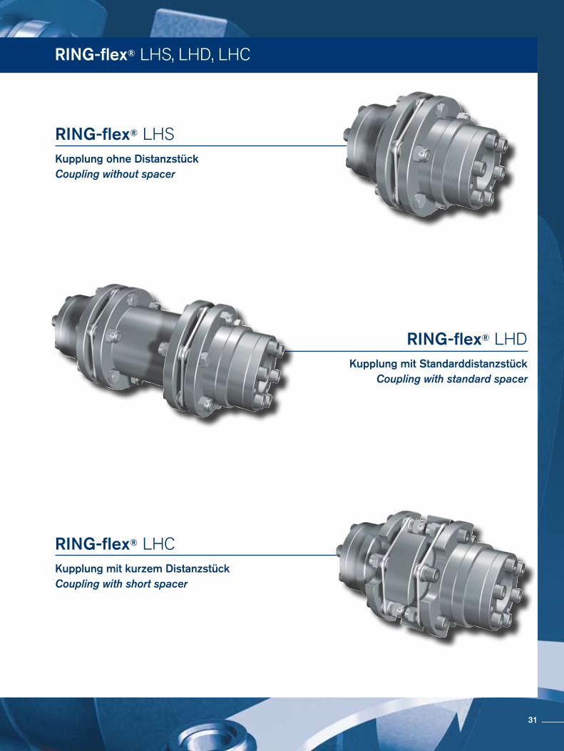
RING-flex® LHS, LHD, LHC
Kupplung ohne DistanzstückCoupling without spacer
Kupplung mit kurzem DistanzstückCoupling with short spacer
Kupplung mit StandarddistanzstückCoupling with standard spacer
RING-flex® LHS
RING-flex® LHD
RING-flex® LHC
31
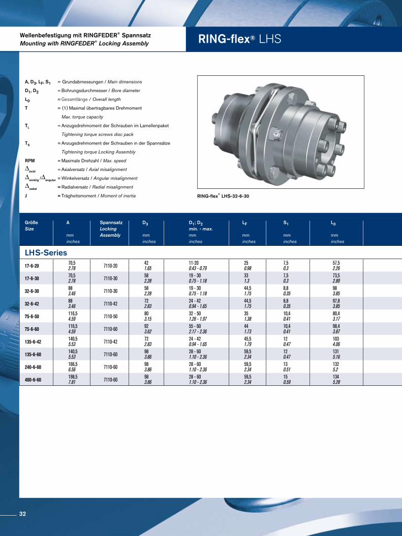
Wellenbefestigung mit RINGFEDER® SpannsatzMounting with RINGFEDER® Locking Assembly RING-flex® LHS
RING-flex® LHS-32-6-30
A, D3, LF, S1 = Grundabmessungen / Main dimensions
D1, D2 = Bohrungsdurchmesser / Bore diameter
L0 = Gesamtlänge / Overall length
T = (1) Maximal übertragbares Drehmoment
Max. torque capacity
TL = Anzugsdrehmoment der Schrauben im Lamellenpaket
Tightening torque screws disc pack
TS = Anzugsdrehmoment der Schrauben in der Spannsätze
Tightening torque Locking Assembly
RPM = Maximale Drehzahl / Max. speed
∆axial = Axialversatz / Axial misalignment
∆winklig /∆angular = Winkelversatz / Angular misalignment
∆radial = Radialversatz / Radial misalignment
J = Trägheitsmoment / Moment of inertia
Größe A Spannsatz D3 D1; D2 LF S1 L0 Größe T TL TS RPM ∆axial ∆winklig Masse JSize Locking min. - max. Size (1) ∆angular Weight
mm Assembly mm mm mm mm mm Nm Nm Nm 1/min ± mm grad kg kg m2
inches inches inches inches inches inches in-lbs ft-lbs ft-lbs ± inches degree lbs lb in2
LHS-Series LHS-Series
17-6-20 70,52.78 7110-20 42
1.6511-200.43 - 0.79
250.98
7,50.3
57,52.26 17-6-20 70
62086
54 8400 0,5
0.02 0,75 1,252.8
0,0001.67
17-6-30 70,52.78 7110-30 58
2.2819 - 300.75 - 1.18
331.3
7,50.3
73,52.89 17-6-30 170
150586
1713 8400 0,5
0.02 0,75 1,252.8
0,0001.67
32-6-30 883.46 7110-30 58
2.2819 - 300.75 - 1.18
44,51.75
8,80.35
983.85 32-6-30 320
28321410
1713 6800 0,6
0.02 0,75 2,455.4
0,0025.6
32-6-42 883.46 7110-42 72
2.8324 - 420.94 - 1.65
44,51.75
8,80.35
97,83.85 32-6-42 320
28321410
1713 6800 0,6
0.02 0,75 2,455.4
0,0025.6
75-6-50 116,54.59 7110-50 80
3.1532 - 501.26 - 1.97
351.38
10,40.41
80,43.17 75-6-50 750
66383123
1713 5400 0,8
0.03 0,75 5,211.5
0,01033.86
75-6-60 116,54.59 7110-60 92
3.6255 - 602.17 - 2.36
441.73
10,40.41
98,43.87 75-6-60 750
66383123
1713 5400 0,8
0.03 0,75 5,211.5
0,01033.86
135-6-42 140,55.53 7110-42 72
2.8324 - 420.94 - 1.65
45,51.79
120.47
1034.06 135-6-42 1350
119496246
1713 4600 1
0.04 0,75 8,218.1
0,01446.44
135-6-60 140,55.53 7110-60 98
3.8628 - 601.10 - 2.36
59,52.34
120.47
1315.16 135-6-60 1350
119496246
4130 4600 1
0.04 0,75 8,218.1
0,01446.44
240-6-60 166,56.56 7110-60 98
3.8628 - 601.10 - 2.36
59,52.34
130.51
1325.2 240-6-60 2400
2124211081
4130 3800 1,2
0.05 0,75 14,732.4
0,035118.74
400-6-60 198,57.81 7110-60 98
3.8628 - 601.10 - 2.36
59,52.34
150.59
1345.28 400-6-60 4000
35403180133
4130 3400 1,4
0.06 0,75 2555.1
0,084285.93
32
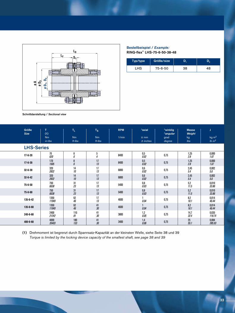
Schnittdarstellung / Sectional view
Bestellbeispiel / Example:RING-flex® LHS-75-6-50-38-48
Typ/type Größe/size D1 D2
LHS 75-6-50 38 48
Größe A Spannsatz D3 D1; D2 LF S1 L0 Größe T TL TS RPM ∆axial ∆winklig Masse JSize Locking min. - max. Size (1) ∆angular Weight
mm Assembly mm mm mm mm mm Nm Nm Nm 1/min ± mm grad kg kg m2
inches inches inches inches inches inches in-lbs ft-lbs ft-lbs ± inches degree lbs lb in2
LHS-Series LHS-Series
17-6-20 70,52.78 7110-20 42
1.6511-200.43 - 0.79
250.98
7,50.3
57,52.26 17-6-20 70
62086
54 8400 0,5
0.02 0,75 1,252.8
0,0001.67
17-6-30 70,52.78 7110-30 58
2.2819 - 300.75 - 1.18
331.3
7,50.3
73,52.89 17-6-30 170
150586
1713 8400 0,5
0.02 0,75 1,252.8
0,0001.67
32-6-30 883.46 7110-30 58
2.2819 - 300.75 - 1.18
44,51.75
8,80.35
983.85 32-6-30 320
28321410
1713 6800 0,6
0.02 0,75 2,455.4
0,0025.6
32-6-42 883.46 7110-42 72
2.8324 - 420.94 - 1.65
44,51.75
8,80.35
97,83.85 32-6-42 320
28321410
1713 6800 0,6
0.02 0,75 2,455.4
0,0025.6
75-6-50 116,54.59 7110-50 80
3.1532 - 501.26 - 1.97
351.38
10,40.41
80,43.17 75-6-50 750
66383123
1713 5400 0,8
0.03 0,75 5,211.5
0,01033.86
75-6-60 116,54.59 7110-60 92
3.6255 - 602.17 - 2.36
441.73
10,40.41
98,43.87 75-6-60 750
66383123
1713 5400 0,8
0.03 0,75 5,211.5
0,01033.86
135-6-42 140,55.53 7110-42 72
2.8324 - 420.94 - 1.65
45,51.79
120.47
1034.06 135-6-42 1350
119496246
1713 4600 1
0.04 0,75 8,218.1
0,01446.44
135-6-60 140,55.53 7110-60 98
3.8628 - 601.10 - 2.36
59,52.34
120.47
1315.16 135-6-60 1350
119496246
4130 4600 1
0.04 0,75 8,218.1
0,01446.44
240-6-60 166,56.56 7110-60 98
3.8628 - 601.10 - 2.36
59,52.34
130.51
1325.2 240-6-60 2400
2124211081
4130 3800 1,2
0.05 0,75 14,732.4
0,035118.74
400-6-60 198,57.81 7110-60 98
3.8628 - 601.10 - 2.36
59,52.34
150.59
1345.28 400-6-60 4000
35403180133
4130 3400 1,4
0.06 0,75 2555.1
0,084285.93
(1) Drehmoment ist begrenzt durch Spannsatz-Kapazität an der kleinsten Welle, siehe Seite 38 und 39 Torque is limited by the locking device capacity of the smallest shaft, see page 38 and 39
33
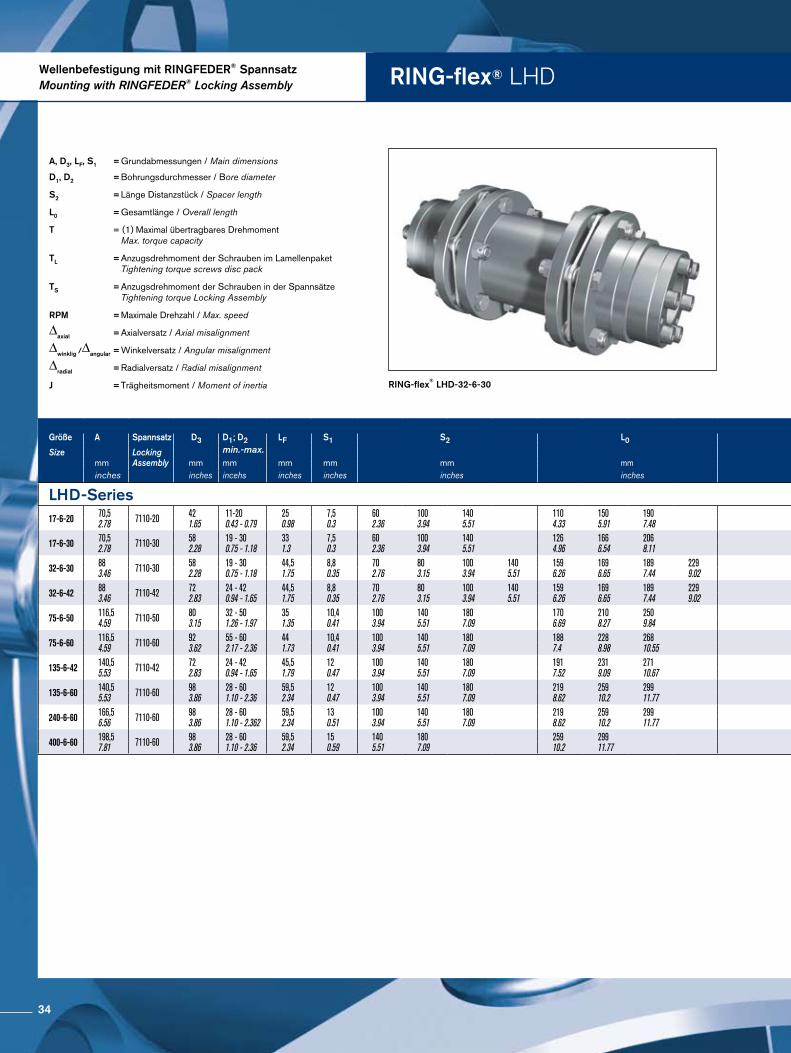
Wellenbefestigung mit RINGFEDER® SpannsatzMounting with RINGFEDER® Locking Assembly RING-flex® LHD
RING-flex® LHD-32-6-30
A, D3, LF, S1 = Grundabmessungen / Main dimensions
D1, D2 = Bohrungsdurchmesser / Bore diameter
S2 = Länge Distanzstück / Spacer length
L0 = Gesamtlänge / Overall length
T = (1) Maximal übertragbares Drehmoment Max. torque capacity
TL = Anzugsdrehmoment der Schrauben im Lamellenpaket Tightening torque screws disc pack
TS = Anzugsdrehmoment der Schrauben in der Spannsätze Tightening torque Locking Assembly
RPM = Maximale Drehzahl / Max. speed
∆axial = Axialversatz / Axial misalignment
∆winklig /∆angular = Winkelversatz / Angular misalignment
∆radial = Radialversatz / Radial misalignment
J = Trägheitsmoment / Moment of inertia
RING-flex® XGD/XHD
Größe A Spannsatz D3 D1; D2 LF S1 S2 L0 Größe T TL TS RPM ∆axial ∆winklig ∆radial Masse J
Size Locking min.-max. Size (1) ∆angularmm Assembly mm mm mm mm mm mm Nm 1/min ±mm grad mm kg kg m2
inches inches incehs inches inches inches inches in-lbs ft-lbs ft-lbs ± nhes degree inches lbs lb in2
LHD-Series LHD-Series17-6-20 70,5
2.78 7110-20 421.65
11-200.43 - 0.79
250.98
7,50.3
602.36
1003.94
1405.51
1104.33
1505.91
1907.48 17-6-20 70
62086
54 8400 1,1
0.04 1,5 0,70.03
1,20.05
1,40.06
1,540.06
1,660.07
1,790.07
0,0012.6
0,0012.77
0,0012.97
17-6-30 70,52.78 7110-30 58
2.2819 - 300.75 - 1.18
331.3
7,50.3
602.36
1003.94
1405.51
1264.96
1666.54
2068.11 17-6-30 170
150586
1713 8400 1,1
0.04 1,5 0,70.03
1,20.05
1,40.06
1,540.06
1,660.07
1,790.07
0,0012.6
0,0012.77
0,0012.97
32-6-30 883.46 7110-30 58
2.2819 - 300.75 - 1.18
44,51.75
8,80.35
702.76
803.15
1003.94
1405.51
1596.26
1696.65
1897.44
2299.02 32-6-30 320
28321410
1713 6800 1,2
0.05 1,5 0,80.03
0,90.04
1,20.05
3,090.12
3,150.12
3,260.13
3,480.14
0,0038.61
0,0038.75
0,0039.05
0,0039.64
32-6-42 883.46 7110-42 72
2.8324 - 420.94 - 1.65
44,51.75
8,80.35
702.76
803.15
1003.94
1405.51
1596.26
1696.65
1897.44
2299.02 32-6-42 320
28321410
1713 6800 1,2
0.05 1,5 0,80.03
0,90.04
1,20.05
3,090.12
3,150.12
3,260.13
3,480.14
0,0038.61
0,0038.75
0,0039.05
0,0039.64
75-6-50 116,54.59 7110-50 80
3.1532 - 501.26 - 1.97
351.35
10,40.41
1003.94
1405.51
1807.09
1706.69
2108.27
2509.84 75-6-50 750
66383123
1713 5400 1,6
0.06 1,5 1,20.05
1,70.07
2,20.09
6,550.26
6,850.27
7,140.28
0,00931.71
0,01033.69
0,01035.77
75-6-60 116,54.59 7110-60 92
3.6255 - 602.17 - 2.36
441.73
10,40.41
1003.94
1405.51
1807.09
1887.4
2288.98
26810.55 75-6-60 750
66383123
1713 5400 1,6
0.06 1,5 1,20.05
1,70.07
2,20.09
6,550.26
6,850.27
7,140.28
0,00931.71
0,01033.69
0,01035.77
135-6-42 140,55.53 7110-42 72
2.8324 - 420.94 - 1.65
45,51.79
120.47
1003.94
1405.51
1807.09
1917.52
2319.09
27110.67 135-6-42 1350
119496246
1713 4600 2,1
0.08 1,5 1,10.04
1,70.07
2,20.09
10,290.41
10,720.42
11,160.44
0,02171.52
0,02274.45
0,02377.36
135-6-60 140,55.53 7110-60 98
3.8628 - 601.10 - 2.36
59,52.34
120.47
1003.94
1405.51
1807.09
2198.62
25910.2
29911.77 135-6-60 1350
119496246
4130 4600 2,1
0.08 1,5 1,10.04
1,70.07
2,20.09
10,290.41
10,720.42
11,160.44
0,02171.52
0,02274.45
0,02377.36
240-6-60 166,56.56 7110-60 98
3.8628 - 601.10 - 2.362
59,52.34
130.51
1003.94
1405.51
1807.09
2198.62
25910.2
29911.77 240-6-60 2400
2124211081
4130 3800 2,5
0.1 1,5 1,10.04
1,70.07
2,20.09
17,810.7
18,50.73
19,190.76
0,052176.82
0,054183.79
0,056190.8
400-6-60 198,57.81 7110-60 98
3.8628 - 601.10 - 2.36
59,52.34
150.59
1405.51
1807.09
25910.2
29911.77 400-6-60 4000
35403180133
4130 3400 2,8
0.11 1,5 1,60.06
2,20.09
30,131.19
30,921.22
0,124424.14
0,127435.18
34
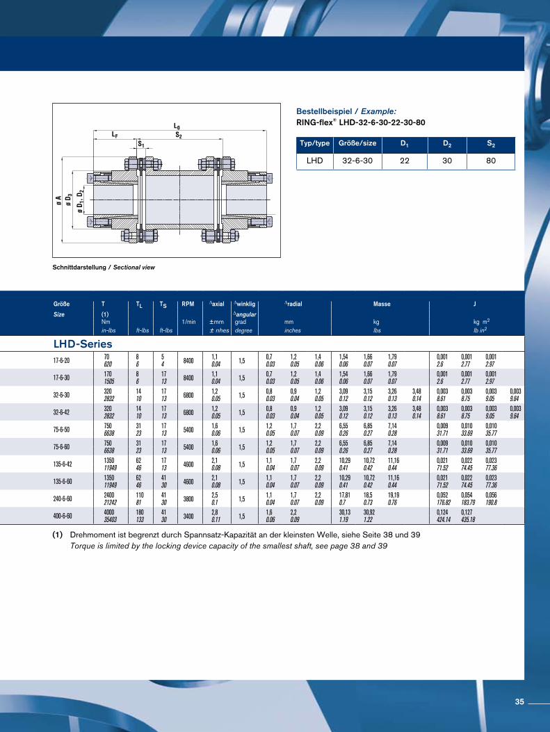
Schnittdarstellung / Sectional view
Bestellbeispiel / Example:RING-flex® LHD-32-6-30-22-30-80
Typ/type Größe/size D1 D2 S2
LHD 32-6-30 22 30 80
(1) Drehmoment ist begrenzt durch Spannsatz-Kapazität an der kleinsten Welle, siehe Seite 38 und 39 Torque is limited by the locking device capacity of the smallest shaft, see page 38 and 39
Größe A Spannsatz D3 D1; D2 LF S1 S2 L0 Größe T TL TS RPM ∆axial ∆winklig ∆radial Masse J
Size Locking min.-max. Size (1) ∆angularmm Assembly mm mm mm mm mm mm Nm 1/min ±mm grad mm kg kg m2
inches inches incehs inches inches inches inches in-lbs ft-lbs ft-lbs ± nhes degree inches lbs lb in2
LHD-Series LHD-Series17-6-20 70,5
2.78 7110-20 421.65
11-200.43 - 0.79
250.98
7,50.3
602.36
1003.94
1405.51
1104.33
1505.91
1907.48 17-6-20 70
62086
54 8400 1,1
0.04 1,5 0,70.03
1,20.05
1,40.06
1,540.06
1,660.07
1,790.07
0,0012.6
0,0012.77
0,0012.97
17-6-30 70,52.78 7110-30 58
2.2819 - 300.75 - 1.18
331.3
7,50.3
602.36
1003.94
1405.51
1264.96
1666.54
2068.11 17-6-30 170
150586
1713 8400 1,1
0.04 1,5 0,70.03
1,20.05
1,40.06
1,540.06
1,660.07
1,790.07
0,0012.6
0,0012.77
0,0012.97
32-6-30 883.46 7110-30 58
2.2819 - 300.75 - 1.18
44,51.75
8,80.35
702.76
803.15
1003.94
1405.51
1596.26
1696.65
1897.44
2299.02 32-6-30 320
28321410
1713 6800 1,2
0.05 1,5 0,80.03
0,90.04
1,20.05
3,090.12
3,150.12
3,260.13
3,480.14
0,0038.61
0,0038.75
0,0039.05
0,0039.64
32-6-42 883.46 7110-42 72
2.8324 - 420.94 - 1.65
44,51.75
8,80.35
702.76
803.15
1003.94
1405.51
1596.26
1696.65
1897.44
2299.02 32-6-42 320
28321410
1713 6800 1,2
0.05 1,5 0,80.03
0,90.04
1,20.05
3,090.12
3,150.12
3,260.13
3,480.14
0,0038.61
0,0038.75
0,0039.05
0,0039.64
75-6-50 116,54.59 7110-50 80
3.1532 - 501.26 - 1.97
351.35
10,40.41
1003.94
1405.51
1807.09
1706.69
2108.27
2509.84 75-6-50 750
66383123
1713 5400 1,6
0.06 1,5 1,20.05
1,70.07
2,20.09
6,550.26
6,850.27
7,140.28
0,00931.71
0,01033.69
0,01035.77
75-6-60 116,54.59 7110-60 92
3.6255 - 602.17 - 2.36
441.73
10,40.41
1003.94
1405.51
1807.09
1887.4
2288.98
26810.55 75-6-60 750
66383123
1713 5400 1,6
0.06 1,5 1,20.05
1,70.07
2,20.09
6,550.26
6,850.27
7,140.28
0,00931.71
0,01033.69
0,01035.77
135-6-42 140,55.53 7110-42 72
2.8324 - 420.94 - 1.65
45,51.79
120.47
1003.94
1405.51
1807.09
1917.52
2319.09
27110.67 135-6-42 1350
119496246
1713 4600 2,1
0.08 1,5 1,10.04
1,70.07
2,20.09
10,290.41
10,720.42
11,160.44
0,02171.52
0,02274.45
0,02377.36
135-6-60 140,55.53 7110-60 98
3.8628 - 601.10 - 2.36
59,52.34
120.47
1003.94
1405.51
1807.09
2198.62
25910.2
29911.77 135-6-60 1350
119496246
4130 4600 2,1
0.08 1,5 1,10.04
1,70.07
2,20.09
10,290.41
10,720.42
11,160.44
0,02171.52
0,02274.45
0,02377.36
240-6-60 166,56.56 7110-60 98
3.8628 - 601.10 - 2.362
59,52.34
130.51
1003.94
1405.51
1807.09
2198.62
25910.2
29911.77 240-6-60 2400
2124211081
4130 3800 2,5
0.1 1,5 1,10.04
1,70.07
2,20.09
17,810.7
18,50.73
19,190.76
0,052176.82
0,054183.79
0,056190.8
400-6-60 198,57.81 7110-60 98
3.8628 - 601.10 - 2.36
59,52.34
150.59
1405.51
1807.09
25910.2
29911.77 400-6-60 4000
35403180133
4130 3400 2,8
0.11 1,5 1,60.06
2,20.09
30,131.19
30,921.22
0,124424.14
0,127435.18
35
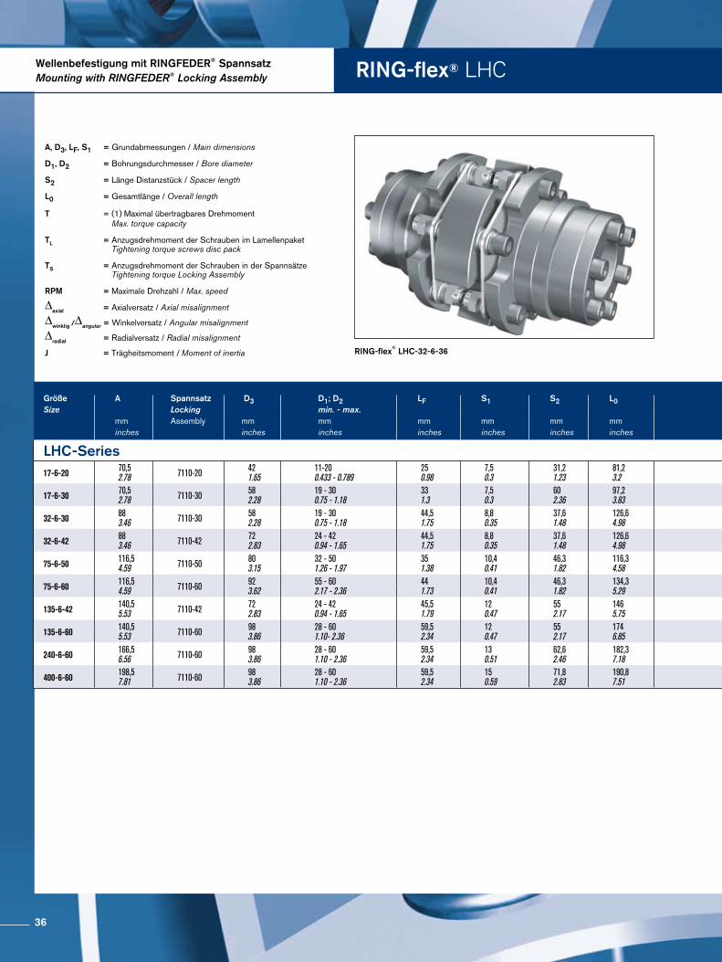
RING-flex® LHC
RING-flex® LHC-32-6-36
A, D3, LF, S1 = Grundabmessungen / Main dimensions
D1, D2 = Bohrungsdurchmesser / Bore diameter
S2 = Länge Distanzstück / Spacer length
L0 = Gesamtlänge / Overall length
T = (1) Maximal übertragbares Drehmoment Max. torque capacity
TL = Anzugsdrehmoment der Schrauben im Lamellenpaket Tightening torque screws disc pack
TS = Anzugsdrehmoment der Schrauben in der Spannsätze Tightening torque Locking Assembly
RPM = Maximale Drehzahl / Max. speed
∆axial = Axialversatz / Axial misalignment
∆winklig /∆angular = Winkelversatz / Angular misalignment
∆radial = Radialversatz / Radial misalignment
J = Trägheitsmoment / Moment of inertia
Wellenbefestigung mit RINGFEDER® SpannsatzMounting with RINGFEDER® Locking Assembly
Größe A Spannsatz D3 D1; D2 LF S1 S2 L0 Größe T TL TS RPM ∆axial ∆winklig ∆radial Masse JSize Locking min. - max. Size (1) Δangular Weight
mm Assembly mm mm mm mm mm mm Nm Nm Nm 1/min ± mm grad mm kg kg m2
inches inches inches inches inches inches inches in-lbs in-lbs ft-lbs ± inches degree inches lbs lb in2
LHC-Series LHC-Series17-6-20 70,5
2.78 7110-20 421.65
11-200.433 - 0.789
250.98
7,50.3
31,21.23
81,23.2 17-6-20 70
62086
54 8400 1,1
0.04 1,5 0,30.01
1,440.06
0,0012.43
17-6-30 70,52.78 7110-30 58
2.2819 - 300.75 - 1.18
331.3
7,50.3
602.36
97,23.83 17-6-30 170
150586
1713 8400 1,1
0.04 1,5 0,30.01
1,440.06
0,0012.43
32-6-30 883.46 7110-30 58
2.2819 - 300.75 - 1.18
44,51.75
8,80.35
37,61.48
126,64.98 32-6-30 320
28321410
1713 6800 1,2
0.05 1,5 0,40.02
2,890.11
0,0027.45
32-6-42 883.46 7110-42 72
2.8324 - 420.94 - 1.65
44,51.75
8,80.35
37,61.48
126,64.98 32-6-42 320
28321410
1713 6800 1,2
0.05 1,5 0,40.02
2,890.11
0,0027.45
75-6-50 116,54.59 7110-50 80
3.1532 - 501.26 - 1.97
351.38
10,40.41
46,31.82
116,34.58 75-6-50 750
66383123
1713 5400 1,6
0.06 1,5 0,50.02
6,160.24
0,00827.2
75-6-60 116,54.59 7110-60 92
3.6255 - 602.17 - 2.36
441.73
10,40.41
46,31.82
134,35.29 75-6-60 750
66383123
1713 5400 1,6
0.06 1,5 0,50.02
6,160.24
0,00827.2
135-6-42 140,55.53 7110-42 72
2.8324 - 420.94 - 1.65
45,51.79
120.47
552.17
1465.75 135-6-42 1350
119496246
1713 4600 2,1
0.08 1,5 0,70.03
10,120.4
0,01862.32
135-6-60 140,55.53 7110-60 98
3.8628 - 601.10- 2.36
59,52.34
120.47
552.17
1746.85 135-6-60 1350
119496246
4130 4600 2,1
0.08 1,5 0,70.03
10,120.4
0,01862.32
240-6-60 166,56.56 7110-60 98
3.8628 - 601.10 - 2.36
59,52.34
130.51
62,62.46
182,37.18 240-6-60 2400
2124211081
4130 3800 2,5
0.1 1,5 0,70.03
17,150.68
0,050170.78
400-6-60 198,57.81 7110-60 98
3.8628 - 601.10 - 2.36
59,52.34
150.59
71,82.83
190,87.51 400-6-60 4000
35403180133
4130 3400 2,8
0.11 1,5 0,70.03
29,591.16
0,122416.28
36
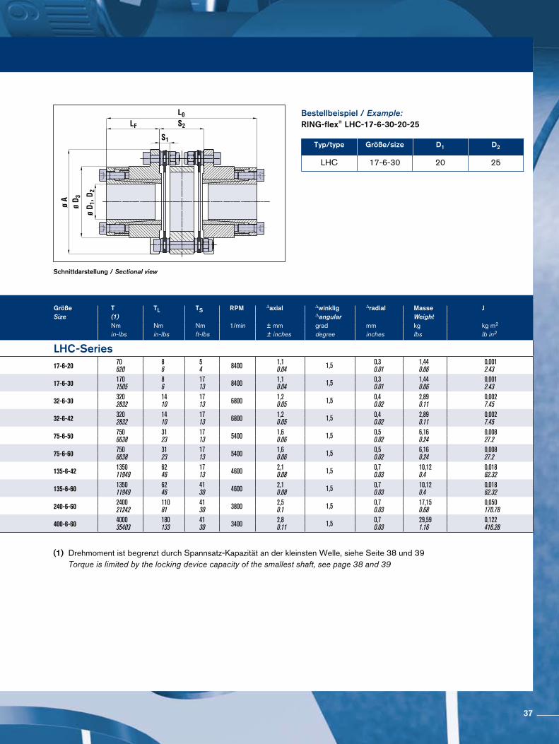
Schnittdarstellung / Sectional view
Bestellbeispiel / Example:RING-flex® LHC-17-6-30-20-25
Typ/type Größe/size D1 D2
LHC 17-6-30 20 25
(1) Drehmoment ist begrenzt durch Spannsatz-Kapazität an der kleinsten Welle, siehe Seite 38 und 39 Torque is limited by the locking device capacity of the smallest shaft, see page 38 and 39
Größe A Spannsatz D3 D1; D2 LF S1 S2 L0 Größe T TL TS RPM ∆axial ∆winklig ∆radial Masse JSize Locking min. - max. Size (1) Δangular Weight
mm Assembly mm mm mm mm mm mm Nm Nm Nm 1/min ± mm grad mm kg kg m2
inches inches inches inches inches inches inches in-lbs in-lbs ft-lbs ± inches degree inches lbs lb in2
LHC-Series LHC-Series17-6-20 70,5
2.78 7110-20 421.65
11-200.433 - 0.789
250.98
7,50.3
31,21.23
81,23.2 17-6-20 70
62086
54 8400 1,1
0.04 1,5 0,30.01
1,440.06
0,0012.43
17-6-30 70,52.78 7110-30 58
2.2819 - 300.75 - 1.18
331.3
7,50.3
602.36
97,23.83 17-6-30 170
150586
1713 8400 1,1
0.04 1,5 0,30.01
1,440.06
0,0012.43
32-6-30 883.46 7110-30 58
2.2819 - 300.75 - 1.18
44,51.75
8,80.35
37,61.48
126,64.98 32-6-30 320
28321410
1713 6800 1,2
0.05 1,5 0,40.02
2,890.11
0,0027.45
32-6-42 883.46 7110-42 72
2.8324 - 420.94 - 1.65
44,51.75
8,80.35
37,61.48
126,64.98 32-6-42 320
28321410
1713 6800 1,2
0.05 1,5 0,40.02
2,890.11
0,0027.45
75-6-50 116,54.59 7110-50 80
3.1532 - 501.26 - 1.97
351.38
10,40.41
46,31.82
116,34.58 75-6-50 750
66383123
1713 5400 1,6
0.06 1,5 0,50.02
6,160.24
0,00827.2
75-6-60 116,54.59 7110-60 92
3.6255 - 602.17 - 2.36
441.73
10,40.41
46,31.82
134,35.29 75-6-60 750
66383123
1713 5400 1,6
0.06 1,5 0,50.02
6,160.24
0,00827.2
135-6-42 140,55.53 7110-42 72
2.8324 - 420.94 - 1.65
45,51.79
120.47
552.17
1465.75 135-6-42 1350
119496246
1713 4600 2,1
0.08 1,5 0,70.03
10,120.4
0,01862.32
135-6-60 140,55.53 7110-60 98
3.8628 - 601.10- 2.36
59,52.34
120.47
552.17
1746.85 135-6-60 1350
119496246
4130 4600 2,1
0.08 1,5 0,70.03
10,120.4
0,01862.32
240-6-60 166,56.56 7110-60 98
3.8628 - 601.10 - 2.36
59,52.34
130.51
62,62.46
182,37.18 240-6-60 2400
2124211081
4130 3800 2,5
0.1 1,5 0,70.03
17,150.68
0,050170.78
400-6-60 198,57.81 7110-60 98
3.8628 - 601.10 - 2.36
59,52.34
150.59
71,82.83
190,87.51 400-6-60 4000
35403180133
4130 3400 2,8
0.11 1,5 0,70.03
29,591.16
0,122416.28
37
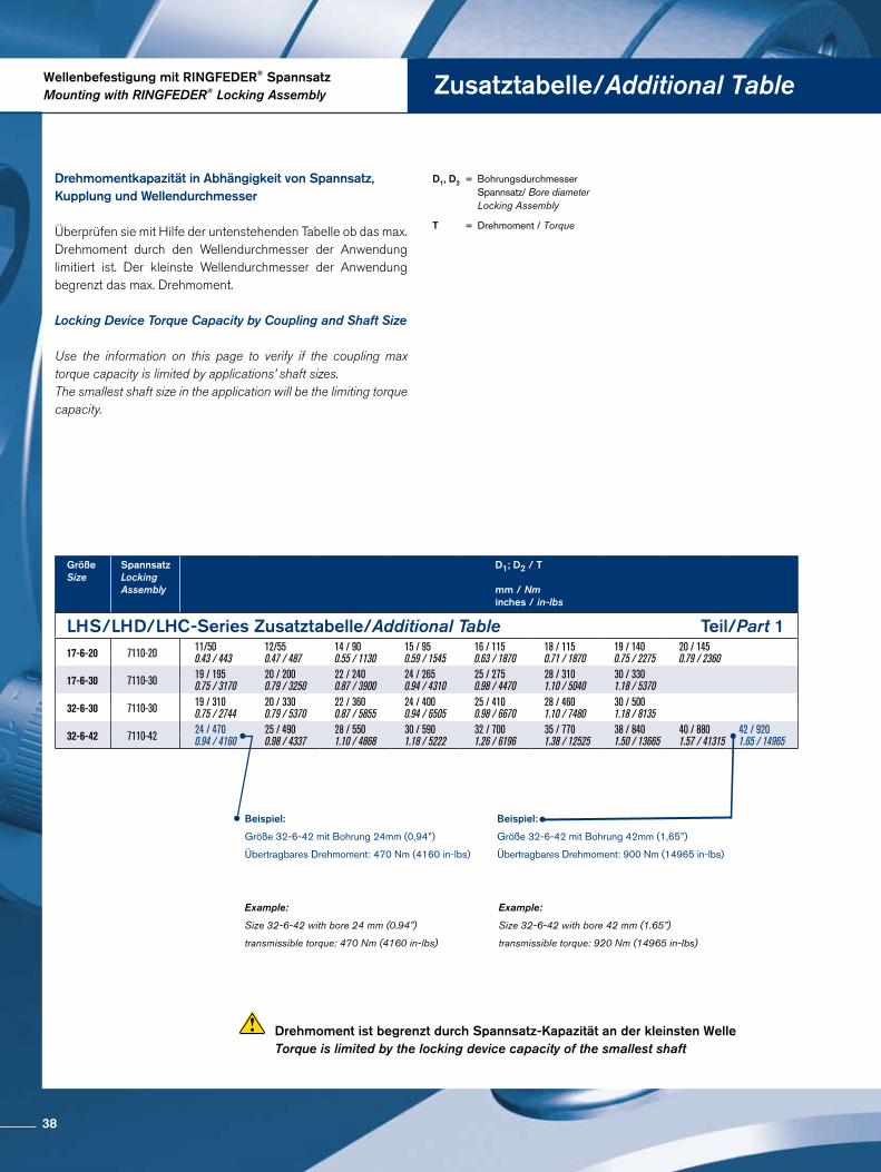
Wellenbefestigung mit RINGFEDER® SpannsatzMounting with RINGFEDER® Locking Assembly Zusatztabelle/Additional Table
Beispiel:
Größe 32-6-42 mit Bohrung 42mm (1,65”)
Übertragbares Drehmoment: 900 Nm (14965 in-lbs)
D1, D2 = Bohrungsdurchmesser Spannsatz/ Bore diameter Locking Assembly
T = Drehmoment / Torque
GrößeSize
Spannsatz LockingAssembly
D1; D2 / T mm / Nminches / in-lbs
LHS/LHD/LHC-Series Zusatztabelle/Additional Table Teil/Part 117-6-20 7110-20 11/50
0.43 / 44312/550.47 / 487
14 / 900.55 / 1130
15 / 950.59 / 1545
16 / 1150.63 / 1870
18 / 1150.71 / 1870
19 / 1400.75 / 2275
20 / 1450.79 / 2360
17-6-30 7110-30 19 / 1950.75 / 3170
20 / 2000.79 / 3250
22 / 2400.87 / 3900
24 / 2650.94 / 4310
25 / 2750.98 / 4470
28 / 3101.10 / 5040
30 / 3301.18 / 5370
32-6-30 7110-30 19 / 3100.75 / 2744
20 / 3300.79 / 5370
22 / 3600.87 / 5855
24 / 4000.94 / 6505
25 / 4100.98 / 6670
28 / 4601.10 / 7480
30 / 5001.18 / 8135
32-6-42 7110-42 24 / 4700.94 / 4160
25 / 4900.98 / 4337
28 / 5501.10 / 4868
30 / 5901.18 / 5222
32 / 7001.26 / 6196
35 / 7701.38 / 12525
38 / 8401.50 / 13665
40 / 8801.57 / 41315
42 / 9201.65 / 14965
Beispiel:
Größe 32-6-42 mit Bohrung 24mm (0,94”)
Übertragbares Drehmoment: 470 Nm (4160 in-lbs)
Example:
Size 32-6-42 with bore 42 mm (1.65”)
transmissible torque: 920 Nm (14965 in-lbs)
Example:
Size 32-6-42 with bore 24 mm (0.94”)
transmissible torque: 470 Nm (4160 in-lbs)
Drehmoment ist begrenzt durch Spannsatz-Kapazität an der kleinsten Welle Torque is limited by the locking device capacity of the smallest shaft
Locking Device Torque Capacity by Coupling and Shaft Size
Use the information on this page to verify if the coupling max torque capacity is limited by applications’ shaft sizes. The smallest shaft size in the application will be the limiting torque capacity.
Drehmomentkapazität in Abhängigkeit von Spannsatz, Kupplung und Wellendurchmesser
Überprüfen sie mit Hilfe der untenstehenden Tabelle ob das max. Drehmoment durch den Wellendurchmesser der Anwendung limitiert ist. Der kleinste Wellendurchmesser der Anwendung begrenzt das max. Drehmoment.
38
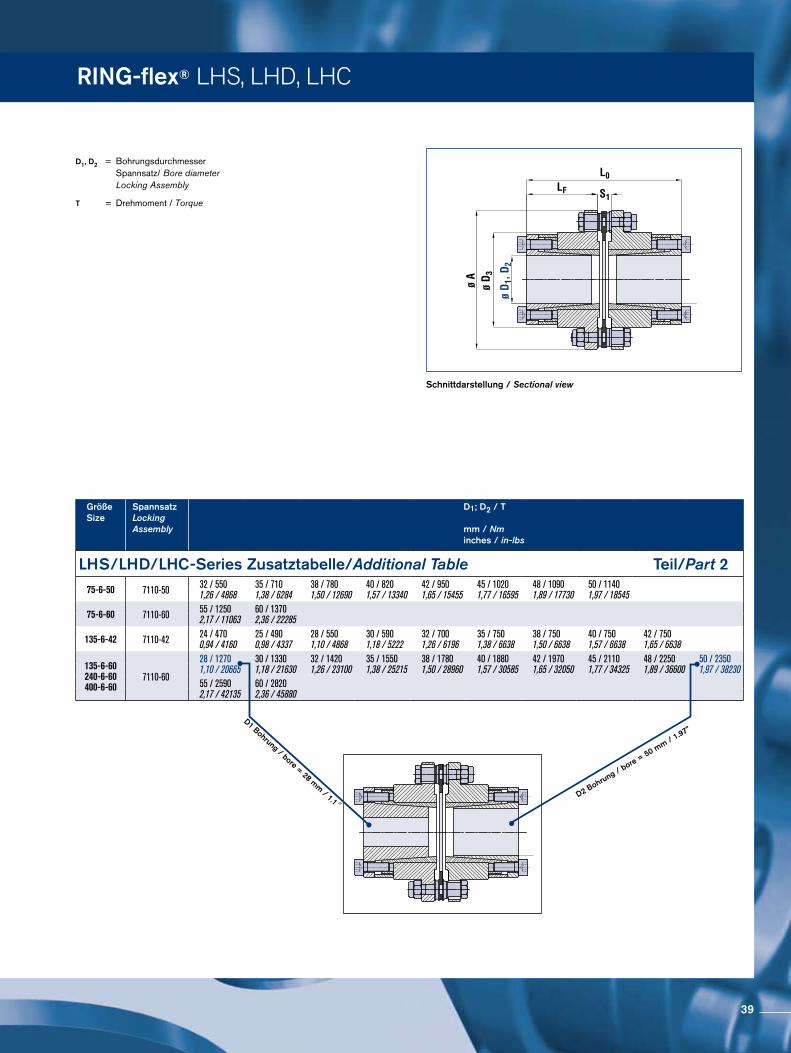
RING-flex® LHS, LHD, LHC
GrößeSize
Spannsatz LockingAssembly
D1; D2 / T mm / Nminches / in-lbs
LHS/LHD/LHC-Series Zusatztabelle/Additional Table Teil/Part 275-6-50 7110-50 32 / 550
1,26 / 486835 / 7101,38 / 6284
38 / 7801,50 / 12690
40 / 8201,57 / 13340
42 / 9501,65 / 15455
45 / 10201,77 / 16595
48 / 10901,89 / 17730
50 / 11401,97 / 18545
75-6-60 7110-60 55 / 12502,17 / 11063
60 / 13702,36 / 22285
135-6-42 7110-42 24 / 4700,94 / 4160
25 / 4900,98 / 4337
28 / 5501,10 / 4868
30 / 5901,18 / 5222
32 / 7001,26 / 6196
35 / 7501,38 / 6638
38 / 7501,50 / 6638
40 / 7501,57 / 6638
42 / 7501,65 / 6638
135-6-60240-6-60400-6-60
28 / 12701,10 / 20665
30 / 13301,18 / 21630
32 / 14201,26 / 23100
35 / 15501,38 / 25215
38 / 17801,50 / 28960
40 / 18801,57 / 30585
42 / 19701,65 / 32050
45 / 21101,77 / 34325
48 / 22501,89 / 36600
50 / 23501,97 / 38230
7110-6055 / 25902,17 / 42135
60 / 28202,36 / 45880
D1 Bohrung / bore = 28 mm / 1.1”D2 Bohrung / b
ore = 50 mm / 1
.97”
D1, D2 = Bohrungsdurchmesser Spannsatz/ Bore diameter Locking Assembly
T = Drehmoment / Torque
Schnittdarstellung / Sectional view
39
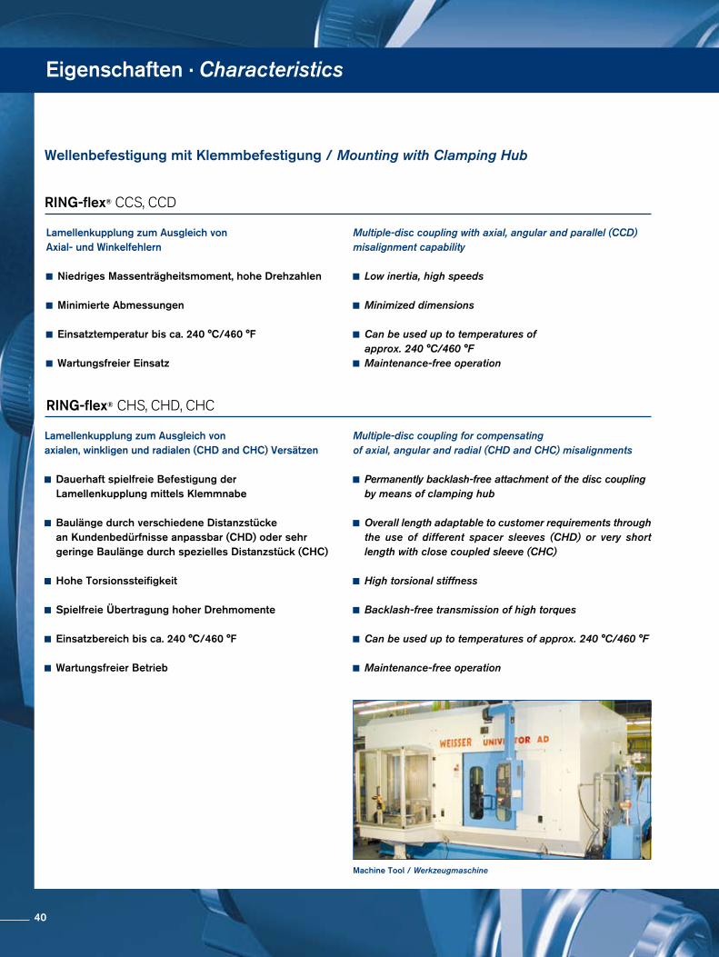
Eigenschaften · Characteristics
Machine Tool / Werkzeugmaschine
Lamellenkupplung zum Ausgleich von Axial- und Winkelfehlern
Niedriges Massenträgheitsmoment, hohe Drehzahlen
Minimierte Abmessungen
Einsatztemperatur bis ca. 240 °C/460 °F
Wartungsfreier Einsatz
Lamellenkupplung zum Ausgleich von axialen, winkligen und radialen (CHD and CHC) Versätzen
Dauerhaft spielfreie Befestigung der Lamellenkupplung mittels Klemmnabe
Baulänge durch verschiedene Distanzstücke an Kundenbedürfnisse anpassbar (CHD) oder sehr geringe Baulänge durch spezielles Distanzstück (CHC)
Hohe Torsionssteifigkeit
Spielfreie Übertragung hoher Drehmomente
Einsatzbereich bis ca. 240 °C/460 °F
Wartungsfreier Betrieb
RING-flex® CCS, CCD
Multiple-disc coupling with axial, angular and parallel (CCD) misalignment capability
Low inertia, high speeds
Minimized dimensions
Can be used up to temperatures of approx. 240 °C/460 °F
Maintenance-free operation
RING-flex® CHS, CHD, CHC
Multiple-disc coupling for compensatingof axial, angular and radial (CHD and CHC) misalignments
Permanently backlash-free attachment of the disc coupling by means of clamping hub
Overall length adaptable to customer requirements through the use of different spacer sleeves (CHD) or very short length with close coupled sleeve (CHC)
High torsional stiffness
Backlash-free transmission of high torques
Can be used up to temperatures of approx. 240 °C/460 °F
Maintenance-free operation
Wellenbefestigung mit Klemmbefestigung / Mounting with Clamping Hub
40
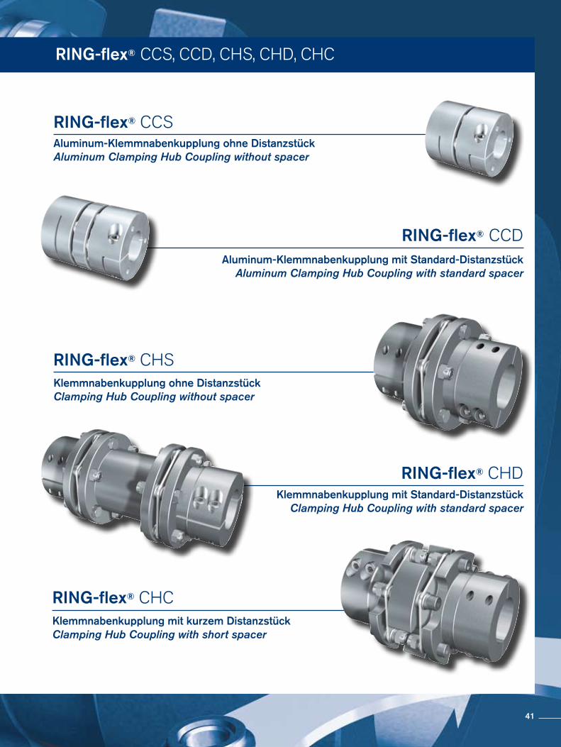
RING-flex® CCS, CCD, CHS, CHD, CHC
Aluminum-Klemmnabenkupplung ohne Distanzstück Aluminum Clamping Hub Coupling without spacer
Klemmnabenkupplung ohne Distanzstück Clamping Hub Coupling without spacer
Aluminum-Klemmnabenkupplung mit Standard-Distanzstück Aluminum Clamping Hub Coupling with standard spacer
RING-flex® CCS
RING-flex® CCD
RING-flex® CHS
Klemmnabenkupplung mit Standard-Distanzstück Clamping Hub Coupling with standard spacer
RING-flex® CHD
Klemmnabenkupplung mit kurzem Distanzstück Clamping Hub Coupling with short spacer
RING-flex® CHC
41
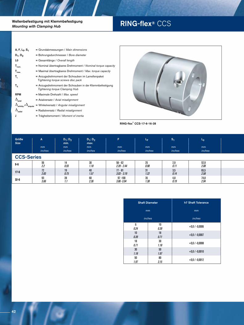
RING-flex® CCSWellenbefestigung mit KlemmbefestigungMounting with Clamping Hub
RING-flex® CCS-17-6-16-28
A, F, LF, S1 = Grundabmessungen / Main dimensions
D1, D2 = Bohrungsdurchmesser / Bore diameter
L0 = Gesamtlänge / Overall length
Tnom. = Nominal übertragbares Drehmoment / Nominal torque capacity
Tmax. = Maximal übertragbares Drehmoment / Max. torque capacity
TL = Anzugsdrehmoment der Schrauben im Lamellenpaket Tightening torque screws disc pack
TS = Anzugsdrehmoment der Schrauben in der Klemmbefestigung Tightening torque Clamping Hub
RPM = Maximale Drehzahl / Max. speed
∆axial = Axialversatz / Axial misalignment
∆winklig /∆angular = Winkelversatz / Angular misalignment
∆radial = Radialversatz / Radial misalignment
J = Trägheitsmoment / Moment of inertia
Größe A D1; D2 D1; D2 F LF S1 L0 Größe Tnom. TL RPM ∆axial ∆winklig Masse JSize min. max. Size (1) ∆angular Weight
mm mm mm mm mm mm mm Nm Nm 1/min ± mm grad kg kg m2
inches inches inches inches inches inches inches in-lbs ft-lbs ± inches degree lbs lb in2
CCS-Series CCS-Series9-6 56
2.2140.55
301.18
58 - 622.28 - 2.44
250.98
2,90.11
52,92.08 9-6 150
132864 10000 0,4
0.016 1 0,30.66
0,00020.54
17-6 722.83
190.75
401.57
77 - 813.03 - 3.19
311.22
3,50.14
65,52.58 17-6 340
300986 8400 0,5
0.02 1 0,61.32
0,00051.6
32-6 933.66
281.1
602.36
97 -1003.86 -3.94
351.38
4,80.19
74,82.94 32-6 550
48681410 6800 0,6
0.024 1 1,072.36
0,00165.48
Shaft Diameter h7 Shaft Tolerance
mm mm
inches inches
6 10+0,0 / -0,0006
0.24 0.3910 18
+0,0 / -0,00070.39 0.7118 30
+0,0 / -0,00080.71 1.1830 50
+0,0 / -0,00101.18 1.9750 80
+0,0 / -0,00121.97 3.15
42
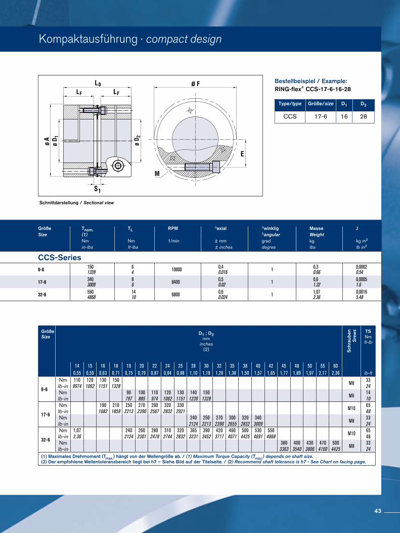
Kompaktausführung · compact design
Schnittdarstellung / Sectional view
Bestellbeispiel / Example:RING-flex® CCS-17-6-16-28
Type/type Größe/size D1 D2
CCS 17-6 16 28
Größe A D1; D2 D1; D2 F LF S1 L0 Größe Tnom. TL RPM ∆axial ∆winklig Masse JSize min. max. Size (1) ∆angular Weight
mm mm mm mm mm mm mm Nm Nm 1/min ± mm grad kg kg m2
inches inches inches inches inches inches inches in-lbs ft-lbs ± inches degree lbs lb in2
CCS-Series CCS-Series9-6 56
2.2140.55
301.18
58 - 622.28 - 2.44
250.98
2,90.11
52,92.08 9-6 150
132864 10000 0,4
0.016 1 0,30.66
0,00020.54
17-6 722.83
190.75
401.57
77 - 813.03 - 3.19
311.22
3,50.14
65,52.58 17-6 340
300986 8400 0,5
0.02 1 0,61.32
0,00051.6
32-6 933.66
281.1
602.36
97 -1003.86 -3.94
351.38
4,80.19
74,82.94 32-6 550
48681410 6800 0,6
0.024 1 1,072.36
0,00165.48
Größe Size
D1 ; D2mm
inches(2) S
chra
uben
S
rew
s TS Nm ft-lb
14 15 16 18 19 20 22 24 25 28 30 32 35 38 40 42 45 48 50 55 600,55 0,59 0,63 0,71 0,75 0,79 0,87 0,94 0,98 1,10 1,18 1,26 1,38 1,50 1,57 1,65 1,77 1,89 1,97 2,17 2,36 lb-ft
9-6
Nm 110 120 130 150 M8 33lb-in 9974 1062 1151 1328 24Nm 90 100 110 120 130 140 150
M614
lb-in 797 885 974 1062 1151 1239 1328 10
17-6
Nm 190 210 250 270 290 320 330 M10 65lb-in 1682 1859 2213 2390 2567 2832 2921 48Nm 240 250 270 300 320 340
M833
lb-in 2124 2213 2390 2655 2832 3009 24
32-6
Nm 1,07 240 260 280 310 320 365 390 420 460 500 530 550 M10 65lb-in 2.36 2124 2301 2478 2744 2832 3231 3452 3717 4071 4425 4691 4868 48Nm 380 400 430 470 500
M833
lb-in 3363 3540 3806 4160 4425 24(1) Maximales Drehmoment (Tmax.) hängt von der Wellengröße ab. / (1) Maximum Torque Capacity (Tmax.) depends on shaft size. (2) Der empfohlene Wellentoleranzbereich liegt bei h7 – Siehe Bild auf der Titelseite. / (2) Recommend shaft tolerance is h7 - See Chart on facing page.
43
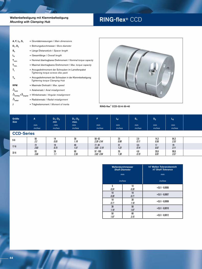
RING-flex® CCDWellenbefestigung mit KlemmbefestigungMounting with Clamping Hub
RING-flex® CCD-32-6-30-40
A, F, LF, S1 = Grundabmessungen / Main dimensions
D1, D2 = Bohrungsdurchmesser / Bore diameter
S2 = Länge Distanzstück / Spacer length
L0 = Gesamtlänge / Overall length
Tnom. = Nominal übertragbares Drehmoment / Nominal torque capacity
Tmax. = Maximal übertragbares Drehmoment / Max. torque capacity
TL = Anzugsdrehmoment der Schrauben im Lamellenpaket Tightening torque screws disc pack
TS = Anzugsdrehmoment der Schrauben in der Klemmbefestigung Tightening torque Clamping Hub
RPM = Maximale Drehzahl / Max. speed
∆axial = Axialversatz / Axial misalignment
∆winklig /∆angular = Winkelversatz / Angular misalignment
∆radial = Radialversatz / Radial misalignment
J = Trägheitsmoment / Moment of inertia
Größe A D1; D2 D1; D2 F LF S1 S2 L0 Größe Tnom. TL RPM ∆axial ∆winklig ∆radial Masse JSize min max. Size ∆angular Weight
mm . mm mm mm mm mm mm mm Nm Nm 1/min ± mm grad mm kg kg m2
inches inches inches inches inches inches inches inches in-lbs ft-lbs ± inches degree inches lbs lb in2
CCD-Series CCD-Series
9-6 562.2
140.55
301.18
58 -622.28 -2.44
250.98
2,90.11
14,30.56
64,32.53 9-6 150
132864 10000 0,8
0.03 1 0,20.008
0,360.8
0,00020.89
17-6 722.83
190.75
401.57
77 -813.03 - 3.19
311.22
3,50.14
170.67
793.11 17-6 340
300986 8400 1
0.04 1 0,20.009
0,731.61
0,00072.48
32-6 933.66
281.1
602.36
97 -1003.82 -3.94
351.38
4,80.19
20,60.81
90,63.57 32-6 550
46861410 6800 1,2
0.05 1 0,30.011
1,32.87
0,00237.94
Wellendurchmesser Shaft Diameter
h7 Wellen Toleranzbereich h7 Shaft Tolerance
mm mm
inches inches
6 10+0,0 / -0,0006
0.24 0.3910 18
+0,0 / -0,00070.39 0.7118 30
+0,0 / -0,00080.71 1.1830 50
+0,0 / -0,00101.18 1.9750 80
+0,0 / -0,00121.97 3.15
44
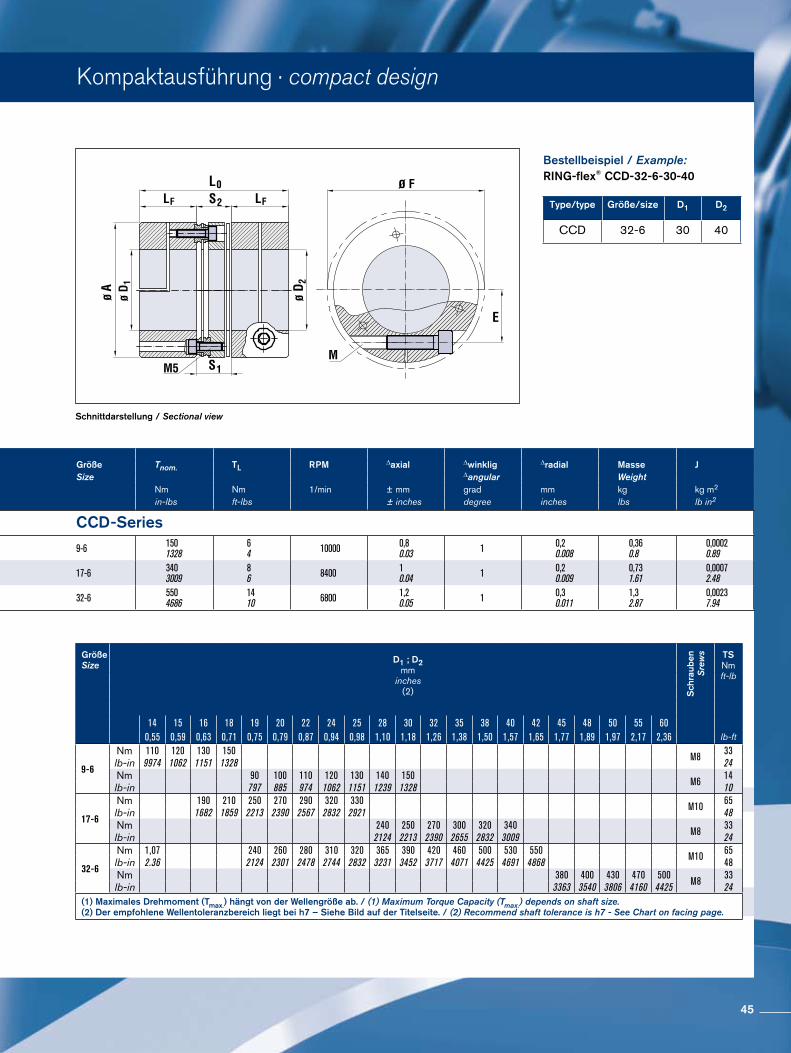
Kompaktausführung · compact design
Schnittdarstellung / Sectional view
Bestellbeispiel / Example:RING-flex® CCD-32-6-30-40
Type/type Größe/size D1 D2
CCD 32-6 30 40
Größe A D1; D2 D1; D2 F LF S1 S2 L0 Größe Tnom. TL RPM ∆axial ∆winklig ∆radial Masse JSize min max. Size ∆angular Weight
mm . mm mm mm mm mm mm mm Nm Nm 1/min ± mm grad mm kg kg m2
inches inches inches inches inches inches inches inches in-lbs ft-lbs ± inches degree inches lbs lb in2
CCD-Series CCD-Series
9-6 562.2
140.55
301.18
58 -622.28 -2.44
250.98
2,90.11
14,30.56
64,32.53 9-6 150
132864 10000 0,8
0.03 1 0,20.008
0,360.8
0,00020.89
17-6 722.83
190.75
401.57
77 -813.03 - 3.19
311.22
3,50.14
170.67
793.11 17-6 340
300986 8400 1
0.04 1 0,20.009
0,731.61
0,00072.48
32-6 933.66
281.1
602.36
97 -1003.82 -3.94
351.38
4,80.19
20,60.81
90,63.57 32-6 550
46861410 6800 1,2
0.05 1 0,30.011
1,32.87
0,00237.94
Größe Size
D1 ; D2mm
inches(2) S
chra
uben
S
rew
s TS Nm ft-lb
14 15 16 18 19 20 22 24 25 28 30 32 35 38 40 42 45 48 50 55 600,55 0,59 0,63 0,71 0,75 0,79 0,87 0,94 0,98 1,10 1,18 1,26 1,38 1,50 1,57 1,65 1,77 1,89 1,97 2,17 2,36 lb-ft
9-6
Nm 110 120 130 150 M8 33lb-in 9974 1062 1151 1328 24Nm 90 100 110 120 130 140 150
M614
lb-in 797 885 974 1062 1151 1239 1328 10
17-6
Nm 190 210 250 270 290 320 330 M10 65lb-in 1682 1859 2213 2390 2567 2832 2921 48Nm 240 250 270 300 320 340
M833
lb-in 2124 2213 2390 2655 2832 3009 24
32-6
Nm 1,07 240 260 280 310 320 365 390 420 460 500 530 550 M10 65lb-in 2.36 2124 2301 2478 2744 2832 3231 3452 3717 4071 4425 4691 4868 48Nm 380 400 430 470 500
M833
lb-in 3363 3540 3806 4160 4425 24(1) Maximales Drehmoment (Tmax.) hängt von der Wellengröße ab. / (1) Maximum Torque Capacity (Tmax.) depends on shaft size. (2) Der empfohlene Wellentoleranzbereich liegt bei h7 – Siehe Bild auf der Titelseite. / (2) Recommend shaft tolerance is h7 - See Chart on facing page.
45
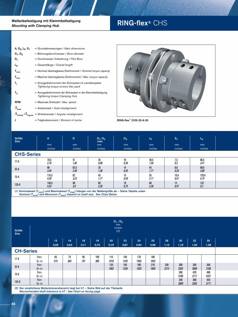
RING-flex® CHSWellenbefestigung mit KlemmbefestigungMounting with Clamping Hub
RING-flex® CHS-32-6-35
A, D3, LF, S1 = Grundabmessungen / Main dimensions
D1, D2 = Bohrungsdurchmesser / Bore diameter
D4 = Durchmesser Vorbohrung / Pilot Bore
L0 = Gesamtlänge / Overall length
Tnom. = Nominal übertragbares Drehmoment / Nominal torque capacity
Tmax. = Maximal übertragbares Drehmoment / Max. torque capacity
TL = Anzugsdrehmoment der Schrauben im Lamellenpaket Tightening torque screws disc pack
TS = Anzugsdrehmoment der Schrauben in der Klemmbefestigung Tightening torque Clamping Hub
RPM = Maximale Drehzahl / Max. speed
∆axial = Axialversatz / Axial misalignment
∆winklig /∆angular = Winkelversatz / Angular misalignment
J = Trägheitsmoment / Moment of inertia
Größe A D D1; D2 D3 LF S1 L0 Größe Tnom. Tmax. TL TS RPM ∆axial ∆winklig Masse JSize max. Size (1) (1) ∆angular Weight
mm mm mm mm mm mm mm Nm Nm Nm Nm 1/min ± mm grad kg kg m2
inches inches inches inches inches inches inches in-lbs in-lbs ft-lbs ft-lbs ± inches degree lbs lb in2
CHS-Series CHS-Series17-6 70,5
2,78471,85
250,98
100,39
39,51,56
7,50,3
86,53,41 17-6 170
15052902567
86
1713 8400 1,1
0,04 2 1,252,8
0,00051,67
32-6 883,46
62,52,46
351,38
140,55
451,77
8,80,35
98,83,89 32-6 320
28325604956
1410
4130 6800 1,2
0,05 2 2,455,4
0,00165,6
75-6 116,54,59
823,23
451,77
150,59
552,17
10,40,41
120,44,74 75-6 750
6638131011594
3123
8361 5400 1,6
0,06 2 5,211,5
0,01033,86
135-6 140,55,53
983,9
602,36
190,75
602,36
120,47
1325,2 135-6 1350
11949236020888
6246
8361 4600 2,1
0,08 2 8,218,1
0,01446,44
(1) Nominalwert (Tnom) und Maximalwert (Tmax) hängen von der Wellengröße ab – Siehe Tabelle unten Nominal (Tnom) and Maximum (Tmax) depend on shaft size, See Chart Below
Größe Size
D1 ; D2mm
inches(2) Größe
Size
Schrauben Größe Screw Size
15 16 18 19 20 22 24 25 28 30 32 35 38 40 42 45 48 50 55 60
0,59 0,63 0,71 0,75 0,79 0,87 0,94 0,98 1,10 1,18 1,26 1,38 1,50 1,57 1,65 1,77 1,89 1,97 2,17 2,36
CH-Series CH-Series
17-6 Nm 65 75 90 100 115 140 170 18017-6 M6
lb-in 575 664 797 885 1018 1239 1505 1593
32-6Nm 120 150 180 210 250 300 350 360
32-6 M8lb-in 1062 1328 1593 1859 2213 2655 3098 3186
75-6Nm 360 420 490
75-6550 650 790 790
M10lb-in 3186 3717 4337 4868 5753 6992 6992
135-6Nm 340 380 420 135-6 470 500 600 650 750 900 1200 1450
M10lb-in 3009 3363 3717 4160 4425 5310 5753 6638 7966 10621 12830(2) Der empfohlene Wellentoleranzbereich liegt bei h7 – Siehe Bild auf der Titelseite Recommended shaft tolerance is h7 - See Chart on facing page
46
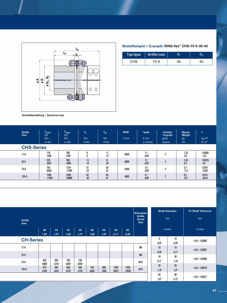
Schnittdarstellung / Sectional view
Bestellbeispiel / Example: RING-flex® CHS-75-6-35-40
Typ/type Größe/size D1 D2
CHS 75-6 35 40
Größe A D D1; D2 D3 LF S1 L0 Größe Tnom. Tmax. TL TS RPM ∆axial ∆winklig Masse JSize max. Size (1) (1) ∆angular Weight
mm mm mm mm mm mm mm Nm Nm Nm Nm 1/min ± mm grad kg kg m2
inches inches inches inches inches inches inches in-lbs in-lbs ft-lbs ft-lbs ± inches degree lbs lb in2
CHS-Series CHS-Series17-6 70,5
2,78471,85
250,98
100,39
39,51,56
7,50,3
86,53,41 17-6 170
15052902567
86
1713 8400 1,1
0,04 2 1,252,8
0,00051,67
32-6 883,46
62,52,46
351,38
140,55
451,77
8,80,35
98,83,89 32-6 320
28325604956
1410
4130 6800 1,2
0,05 2 2,455,4
0,00165,6
75-6 116,54,59
823,23
451,77
150,59
552,17
10,40,41
120,44,74 75-6 750
6638131011594
3123
8361 5400 1,6
0,06 2 5,211,5
0,01033,86
135-6 140,55,53
983,9
602,36
190,75
602,36
120,47
1325,2 135-6 1350
11949236020888
6246
8361 4600 2,1
0,08 2 8,218,1
0,01446,44
(1) Nominalwert (Tnom) und Maximalwert (Tmax) hängen von der Wellengröße ab – Siehe Tabelle unten Nominal (Tnom) and Maximum (Tmax) depend on shaft size, See Chart Below
Größe Size
D1 ; D2mm
inches(2) Größe
Size
Schrauben Größe Screw Size
15 16 18 19 20 22 24 25 28 30 32 35 38 40 42 45 48 50 55 60
0,59 0,63 0,71 0,75 0,79 0,87 0,94 0,98 1,10 1,18 1,26 1,38 1,50 1,57 1,65 1,77 1,89 1,97 2,17 2,36
CH-Series CH-Series
17-6 Nm 65 75 90 100 115 140 170 18017-6 M6
lb-in 575 664 797 885 1018 1239 1505 1593
32-6Nm 120 150 180 210 250 300 350 360
32-6 M8lb-in 1062 1328 1593 1859 2213 2655 3098 3186
75-6Nm 360 420 490
75-6550 650 790 790
M10lb-in 3186 3717 4337 4868 5753 6992 6992
135-6Nm 340 380 420 135-6 470 500 600 650 750 900 1200 1450
M10lb-in 3009 3363 3717 4160 4425 5310 5753 6638 7966 10621 12830(2) Der empfohlene Wellentoleranzbereich liegt bei h7 – Siehe Bild auf der Titelseite Recommended shaft tolerance is h7 - See Chart on facing page
Shaft Diameter h7 Shaft Tolerance
mm mm
inches inches
6 10+0,0 / -0,0006
0,24 0,39
10 18+0,0 / -0,0007
0,39 0,71
18 30+0,0 / -0,0008
0,71 1,18
30 50+0,0 / -0,0010
1,18 1,97
50 80+0,0 / -0,0012
1,97 4,73
47
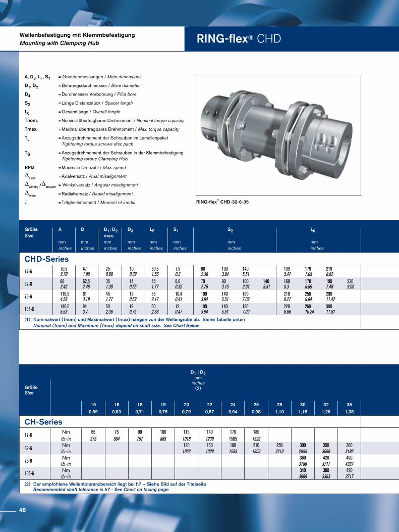
RING-flex® CHDWellenbefestigung mit KlemmbefestigungMounting with Clamping Hub
RING-flex® CHD-32-6-35
A, D3, LF, S1 = Grundabmessungen / Main dimensions
D1, D2 = Bohrungsdurchmesser / Bore diameter
D4 = Durchmesser Vorbohrung / Pilot bore
S2 = Länge Distanzstück / Spacer length
L0 = Gesamtlänge / Overall length
Tnom. = Nominal übertragbares Drehmoment / Nominal torque capacity
Tmax. = Maximal übertragbares Drehmoment / Max. torque capacity
TL = Anzugsdrehmoment der Schrauben im Lamellenpaket Tightening torque screws disc pack
TS = Anzugsdrehmoment der Schrauben in der Klemmbefestigung Tightening torque Clamping Hub
RPM = Maximale Drehzahl / Max. speed
∆axial = Axialversatz / Axial misalignment
∆winklig /∆angular = Winkelversatz / Angular misalignment
∆radial = Radialversatz / Radial misalignment
J = Trägheitsmoment / Moment of inertia
Größe A D D1; D2 D3 LF S1 S2 L0 Größe Tnom. Tmax TL TS RPM ∆axial ∆winklig ∆radial Masse JSize max. Size (1) (1) ∆angular Weight
mm mm mm mm mm mm mm mm Nm Nm Nm Nm Nm ± mm grad mm kg kg m2
inches inches inches inches inches inches inches inches in-lbs in-lbs ft-lbs ft-lbs ft-lbs ± inches degree inches lbs lb in2
CHD-Series CHD-Series17-6 70,5
2.78471.85
250.98
100.39
39,51.56
7,50.3
602.36
1003.94
1405.51
1395.47
1797.05
2198.62 17-6 170
15052902567
86
1713 8400 1,1
0.04 2 0,70.028
1,20.047
1,40.055
1,543.4
1,663.7
1,793.9
0,0012.6
0,0012.77
0,0012.97
32-6 883.46
62,52.46
351.38
140.55
451.77
8,80.35
702.76
803.15
1003.94
1405.51
1606.3
1706.69
1907.48
2309.06 32-6 320
28325604956
1410
4130 6800 1,2
0.05 2 0,80.032
0,90.035
1,20.047
1,70.067
3,096.8
3,156.9
3,267,2
3,487.7
0,0038.61
0,0038.75
0,0039.05
0,0039.64
75-6 116,54.59
813.19
451.77
150.59
552.17
10,40.41
1003.94
1405.51
1807.09
2108.27
2509.84
29011.42 75-6 750
6638131011594
3123
8361 5400 1,6
0.06 2 1,20.047
1,70.067
2,20.087
6,5514.4
6,8515.1
7,1415.7
0,00931.71
0,01033.69
0,01035.77 0
135-6 140,55.53
943.7
602.36
190.75
602.36
120.47
1003.94
1405.51
1807.09
2208.66
26010.24
30011.81 135-6 1350
11949236020888
6246
8361 4600 2,1
0.08 2 1,10.043
1,70.067
2,20.087
10,2922.7
10,7223.6
11,1624.6
0,02171.52
0,02274.45
0,02377.36 0
(1) Nominalwert (Tnom) und Maximalwert (Tmax) hängen von der Wellengröße ab. Siehe Tabelle unten Nominal (Tnom) and Maximum (Tmax) depend on shaft size. See Chart Below
Größe Size
D1 ; D2mm
inches(2)
Größe Size
Schrauben Größe Screw Size
15 16 18 19 20 22 24 25 28 30 32 35 38 40 42 45 48 50 55 60
0,59 0,63 0,71 0,75 0,79 0,87 0,94 0,98 1,10 1,18 1,26 1,38 1,50 1,57 1,65 1,77 1,89 1,97 2,17 2,36
CH-Series CH-Series
17-6 Nm 65 75 90 100 115 140 170 18017-6 M6
lb-in 575 664 797 885 1018 1239 1505 1593
32-6Nm 120 150 180 210 250 300 350 360
32-6 M8lb-in 1062 1328 1593 1859 2213 2655 3098 3186
75-6Nm 360 420 490
75-6550 650 790 790
M10lb-in 3186 3717 4337 4868 5753 6992 6992
135-6Nm 340 380 420 135-6 470 500 600 650 750 900 1200 1450
M10lb-in 3009 3363 3717 4160 4425 5310 5753 6638 7966 10621 12830(2) Der empfohlene Wellentoleranzbereich liegt bei h7 – Siehe Bild auf der Titelseite Recommended shaft tolerance is h7 - See Chart on facing page
48
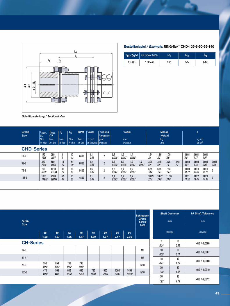
Schnittdarstellung / Sectional view
Bestellbeispiel / Example: RING-flex® CHD-135-6-50-55-140
Typ/type Größe/size D1 D2 S2
CHD 135-6 50 55 140
Größe A D D1; D2 D3 LF S1 S2 L0 Größe Tnom. Tmax TL TS RPM ∆axial ∆winklig ∆radial Masse JSize max. Size (1) (1) ∆angular Weight
mm mm mm mm mm mm mm mm Nm Nm Nm Nm Nm ± mm grad mm kg kg m2
inches inches inches inches inches inches inches inches in-lbs in-lbs ft-lbs ft-lbs ft-lbs ± inches degree inches lbs lb in2
CHD-Series CHD-Series17-6 70,5
2.78471.85
250.98
100.39
39,51.56
7,50.3
602.36
1003.94
1405.51
1395.47
1797.05
2198.62 17-6 170
15052902567
86
1713 8400 1,1
0.04 2 0,70.028
1,20.047
1,40.055
1,543.4
1,663.7
1,793.9
0,0012.6
0,0012.77
0,0012.97
32-6 883.46
62,52.46
351.38
140.55
451.77
8,80.35
702.76
803.15
1003.94
1405.51
1606.3
1706.69
1907.48
2309.06 32-6 320
28325604956
1410
4130 6800 1,2
0.05 2 0,80.032
0,90.035
1,20.047
1,70.067
3,096.8
3,156.9
3,267,2
3,487.7
0,0038.61
0,0038.75
0,0039.05
0,0039.64
75-6 116,54.59
813.19
451.77
150.59
552.17
10,40.41
1003.94
1405.51
1807.09
2108.27
2509.84
29011.42 75-6 750
6638131011594
3123
8361 5400 1,6
0.06 2 1,20.047
1,70.067
2,20.087
6,5514.4
6,8515.1
7,1415.7
0,00931.71
0,01033.69
0,01035.77 0
135-6 140,55.53
943.7
602.36
190.75
602.36
120.47
1003.94
1405.51
1807.09
2208.66
26010.24
30011.81 135-6 1350
11949236020888
6246
8361 4600 2,1
0.08 2 1,10.043
1,70.067
2,20.087
10,2922.7
10,7223.6
11,1624.6
0,02171.52
0,02274.45
0,02377.36 0
(1) Nominalwert (Tnom) und Maximalwert (Tmax) hängen von der Wellengröße ab. Siehe Tabelle unten Nominal (Tnom) and Maximum (Tmax) depend on shaft size. See Chart Below
Größe Size
D1 ; D2mm
inches(2)
Größe Size
Schrauben Größe Screw Size
15 16 18 19 20 22 24 25 28 30 32 35 38 40 42 45 48 50 55 60
0,59 0,63 0,71 0,75 0,79 0,87 0,94 0,98 1,10 1,18 1,26 1,38 1,50 1,57 1,65 1,77 1,89 1,97 2,17 2,36
CH-Series CH-Series
17-6 Nm 65 75 90 100 115 140 170 18017-6 M6
lb-in 575 664 797 885 1018 1239 1505 1593
32-6Nm 120 150 180 210 250 300 350 360
32-6 M8lb-in 1062 1328 1593 1859 2213 2655 3098 3186
75-6Nm 360 420 490
75-6550 650 790 790
M10lb-in 3186 3717 4337 4868 5753 6992 6992
135-6Nm 340 380 420 135-6 470 500 600 650 750 900 1200 1450
M10lb-in 3009 3363 3717 4160 4425 5310 5753 6638 7966 10621 12830(2) Der empfohlene Wellentoleranzbereich liegt bei h7 – Siehe Bild auf der Titelseite Recommended shaft tolerance is h7 - See Chart on facing page
Shaft Diameter h7 Shaft Tolerance
mm mm
inches inches
6 10+0,0 / -0,0006
0.24 0.3910 18
+0,0 / -0,00070.39 0.7118 30
+0,0 / -0,00080.71 1.1830 50
+0,0 / -0,00101.18 1.9750 80
+0,0 / -0,00121.97 4.73
49
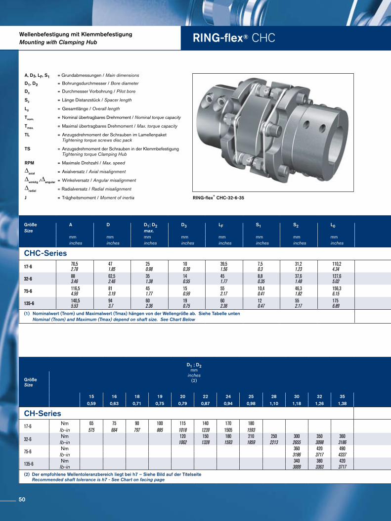
RING-flex® CHCWellenbefestigung mit KlemmbefestigungMounting with Clamping Hub
RING-flex® CHC-32-6-35
A, D3, LF, S1 = Grundabmessungen / Main dimensions
D1, D2 = Bohrungsdurchmesser / Bore diameter
D3 = Durchmesser Vorbohrung / Pilot bore
S2 = Länge Distanzstück / Spacer length
L0 = Gesamtlänge / Overall length
Tnom. = Nominal übertragbares Drehmoment / Nominal torque capacity
Tmax. = Maximal übertragbares Drehmoment / Max. torque capacity
TL = Anzugsdrehmoment der Schrauben im Lamellenpaket Tightening torque screws disc pack
TS = Anzugsdrehmoment der Schrauben in der Klemmbefestigung Tightening torque Clamping Hub
RPM = Maximale Drehzahl / Max. speed
∆axial = Axialversatz / Axial misalignment
∆winklig /∆angular = Winkelversatz / Angular misalignment
∆radial = Radialversatz / Radial misalignment
J = Trägheitsmoment / Moment of inertia
Größe A D D1; D2 D3 LF S1 S2 L0 Größe Tnom. Tmax. TL TS RPM ∆axial ∆winklig ∆radial Masse JSize max. Size (1) (1) ∆angular Weight
mm mm mm mm mm mm mm mm Nm Nm Nm Nm 1/min ± mm grad mm kg kg m2
inches inches inches inches inches inches inches inches in-lbs in-lbs ft-lbs ft-lbs ± inches degree inches lbs lb in2
CHC-Series CHC-Series
17-6 70,52.78
471.85
250.98
100.39
39,51.56
7,50.3
31,21.23
110,24.34 17-6 170
15052902567
86
1713 8400 1,1
0.04 1,5 0,30.012
1,483.3
0,0012.43
32-6 883.46
62,52.46
351.38
140.55
451.77
8,80.35
37,61.48
127,65.02 32-6 320
28325604956
1410
4130 6800 1,2
0.05 1,5 0,40.016
2,96.4
0,0027.45
75-6 116,54.59
813.19
451.77
150.59
552.17
10,40.41
46,31.82
156,36.15 75-6 750
6638131011594
3123
8361 5400 1,6
0.06 1,5 0,50.020
6,213.7
0,00827.2
135-6 140,55.53
943.7
602.36
190.75
602.36
120.47
552.17
1756.89 135-6 1350
11949236020888
6246
8361 4600 2,1
0.08 1,5 0,70.028
9,721.4
0,01862.32
(1) Nominalwert (Tnom) und Maximalwert (Tmax) hängen von der Wellengröße ab. Siehe Tabelle unten Nominal (Tnom) and Maximum (Tmax) depend on shaft size. See Chart Below
Größe Size
D1 ; D2mm
inches(2)
Größe Size
Schrauben Größe Screw Size
15 16 18 19 20 22 24 25 28 30 32 35 38 40 42 45 48 50 55 60
0,59 0,63 0,71 0,75 0,79 0,87 0,94 0,98 1,10 1,18 1,26 1,38 1,50 1,57 1,65 1,77 1,89 1,97 2,17 2,36
CH-Series CH-Series
17-6 Nm 65 75 90 100 115 140 170 18017-6 M6
lb-in 575 664 797 885 1018 1239 1505 1593
32-6Nm 120 150 180 210 250 300 350 360
32-6 M8lb-in 1062 1328 1593 1859 2213 2655 3098 3186
75-6Nm 360 420 490
75-6550 650 790 790
M10lb-in 3186 3717 4337 4868 5753 6992 6992
135-6Nm 340 380 420 135-6 470 500 600 650 750 900 1200 1450
M10lb-in 3009 3363 3717 4160 4425 5310 5753 6638 7966 10621 12830(2) Der empfohlene Wellentoleranzbereich liegt bei h7 – Siehe Bild auf der Titelseite Recommended shaft tolerance is h7 - See Chart on facing page
50
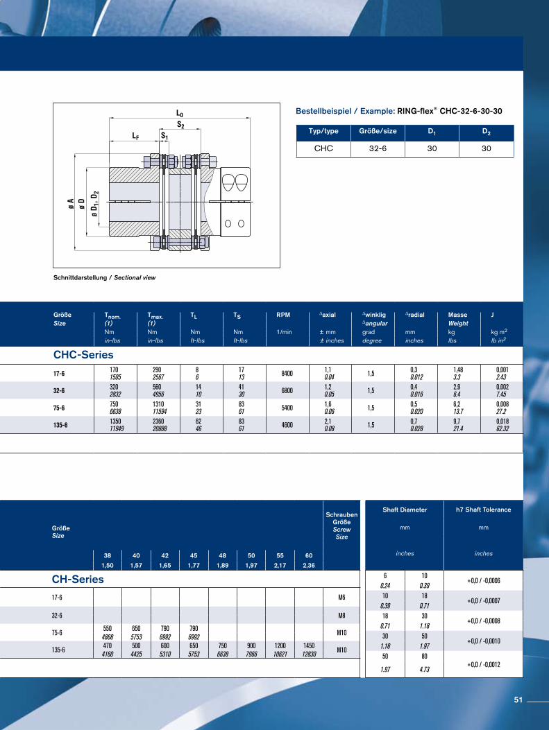
Schnittdarstellung / Sectional view
Bestellbeispiel / Example: RING-flex® CHC-32-6-30-30
Typ/type Größe/size D1 D2
CHC 32-6 30 30
Größe A D D1; D2 D3 LF S1 S2 L0 Größe Tnom. Tmax. TL TS RPM ∆axial ∆winklig ∆radial Masse JSize max. Size (1) (1) ∆angular Weight
mm mm mm mm mm mm mm mm Nm Nm Nm Nm 1/min ± mm grad mm kg kg m2
inches inches inches inches inches inches inches inches in-lbs in-lbs ft-lbs ft-lbs ± inches degree inches lbs lb in2
CHC-Series CHC-Series
17-6 70,52.78
471.85
250.98
100.39
39,51.56
7,50.3
31,21.23
110,24.34 17-6 170
15052902567
86
1713 8400 1,1
0.04 1,5 0,30.012
1,483.3
0,0012.43
32-6 883.46
62,52.46
351.38
140.55
451.77
8,80.35
37,61.48
127,65.02 32-6 320
28325604956
1410
4130 6800 1,2
0.05 1,5 0,40.016
2,96.4
0,0027.45
75-6 116,54.59
813.19
451.77
150.59
552.17
10,40.41
46,31.82
156,36.15 75-6 750
6638131011594
3123
8361 5400 1,6
0.06 1,5 0,50.020
6,213.7
0,00827.2
135-6 140,55.53
943.7
602.36
190.75
602.36
120.47
552.17
1756.89 135-6 1350
11949236020888
6246
8361 4600 2,1
0.08 1,5 0,70.028
9,721.4
0,01862.32
(1) Nominalwert (Tnom) und Maximalwert (Tmax) hängen von der Wellengröße ab. Siehe Tabelle unten Nominal (Tnom) and Maximum (Tmax) depend on shaft size. See Chart Below
Größe Size
D1 ; D2mm
inches(2)
Größe Size
Schrauben Größe Screw Size
15 16 18 19 20 22 24 25 28 30 32 35 38 40 42 45 48 50 55 60
0,59 0,63 0,71 0,75 0,79 0,87 0,94 0,98 1,10 1,18 1,26 1,38 1,50 1,57 1,65 1,77 1,89 1,97 2,17 2,36
CH-Series CH-Series
17-6 Nm 65 75 90 100 115 140 170 18017-6 M6
lb-in 575 664 797 885 1018 1239 1505 1593
32-6Nm 120 150 180 210 250 300 350 360
32-6 M8lb-in 1062 1328 1593 1859 2213 2655 3098 3186
75-6Nm 360 420 490
75-6550 650 790 790
M10lb-in 3186 3717 4337 4868 5753 6992 6992
135-6Nm 340 380 420 135-6 470 500 600 650 750 900 1200 1450
M10lb-in 3009 3363 3717 4160 4425 5310 5753 6638 7966 10621 12830(2) Der empfohlene Wellentoleranzbereich liegt bei h7 – Siehe Bild auf der Titelseite Recommended shaft tolerance is h7 - See Chart on facing page
Shaft Diameter h7 Shaft Tolerance
mm mm
inches inches
6 10+0,0 / -0,0006
0.24 0.3910 18
+0,0 / -0,00070.39 0.7118 30
+0,0 / -0,00080.71 1.1830 50
+0,0 / -0,00101.18 1.9750 80
+0,0 / -0,00121.97 4.73
51
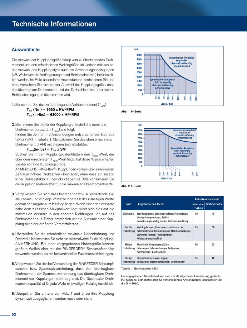
Technische Informationen
Auswahlhilfe
Die Auswahl der Kupplungsgröße hängt vom zu übertragenden Drehmoment und den erforderlichen Wellengrößen ab. Jedoch müssen bei der Auswahl des Kupplungstyps auch die Anwendungsbedingungen (z.B. Wellenversatz, Verlängerungen und Betriebsdrehzahl) berücksichtigt werden. Im Falle besonderer Anwendungen kontaktieren Sie uns bitte. Versichern Sie sich bei der Auswahl der Kupplungsgröße, dass das übertragbare Drehmoment und der Drehzahlbereich unter keinen Betriebsbedingungen überschritten wird.
1. Berechnen Sie das zu übertragende Antriebsmoment (TAN) TAN (Nm) = 9550 x KW/RPM TAN (in-lbs) = 63000 x HP/RPM
2. Bestimmen Sie die für die Kupplung erforderliche nominale Drehmomentkapazität (Tnom) wie folgt: Finden Sie den für Ihre Anwendungen entsprechenden Betriebs faktor (SM) in Tabelle 1. Multiplizieren Sie das oben errechnete Drehmoment (TAN) mit diesem Betriebsfaktor. Tnom(in-lbs) = TAN x SM Suchen Sie in den Kupplungsdatenblättern den TnomWert, der über dem errechneten TnomWert liegt. Auf diese Weise erhalten Sie die korrekte Kupplungsgröße. ANMERKUNG: RINGflex® Kupplungen können über einen kurzen Zeitraum höhere Drehzahlen übertragen, ohne dass ein zusätz licher Betriebsfaktor zu berücksichtigen ist. Bitte konsultieren Sie die Kupplungsdatenblätter für die maximalen Drehmomentwerte.
3. Vergewissern Sie sich, dass bestehende bzw. zu erwartende axi ale, radiale und winklige Versätze innerhalb der zulässigen Werte gemäß der Angaben im Katalog liegen. Wenn einer der Versätze nahe dem zulässigen Maximalwert liegt, wirkt sich dies auf die maximalen Versätze in den anderen Richtungen und auf das Drehmoment aus. Daher empfehlen wir die Auswahl einer Kup plung mit einer größeren Versatztoleranz .
4. Überprüfen Sie die erforderliche maximale Nabenbohrung und Drehzahl. Überschreiten Sie nicht die Maximalwerte für die Kupplung. ANMERKUNG: Bei einer vorgegebenen Nabengröße können größere Wellen eher mit der RINGFEDER® Schrumpfscheibe verwendet werden, als mit konventionellen Passfederverbindungen.
5. Vergewissern Sie sich bei Verwendung der RINGFEDER Schrumpf scheibe bzw. Spannsatzverbindung, dass das übertragbare Drehmoment der Spannsatzverbindung das übertragbare Dreh moment der Kupplungen nicht begrenzt. Die Spannsatz Dreh momentkapazität ist für jede Welle im jeweiligen Katalog ersichtlich.
6. Überprüfen Sie anhand von Abb. 1 and 2, ob ihre Kupplung dynamisch ausgeglichen werden muss oder nicht.
Tabelle 1: Betriebsfaktor (SM)
Die angegebenen Betriebsfaktoren sind nur als allgemeine Orientierung gedacht.Für typische Betriebsfaktoren für verschiedenste Anwendungen, konsultieren Sie die DIN 3990.
Abb. 1: H-Serie
Abb. 2: G-Serie
Antreibendes Gerät
Last Angetriebenes Gerät Motor oder Kolbenmotor Turbine
Gleichmäßig Zentrifugalpumpen; gleichmäßig beladene Förderanlagen; 1.0 1.5 Wechselstromgeneratoren; Gebläse; Generatoren-gleichmäßig beladen; Mischmaschine-flüssig
Leichte Zentrifugalpumpen; Generatoren – pulsierende Last; 1.5 2.0 Erschütterung Schleifmaschinen; Hydraulikpumpen; Maschinenwerkzeuge; Vibrierende Pumpen; Textilmaschinen; Holzbearbeitungsmaschinen
Mittlere Multizylinder-Kompressoren; Kräne; 2.0 2.5 Erschütterung Hebeanlagen; Hebevorrichtungen; Lochpressen; Kolbenpumpen ; Schiffsantriebe
Heftige Einzylinderkompressoren; Bagger; 2.5 3.0 Erschütterung Bohrgestelle; Bergwerksmaschinen; Gummimischer
52
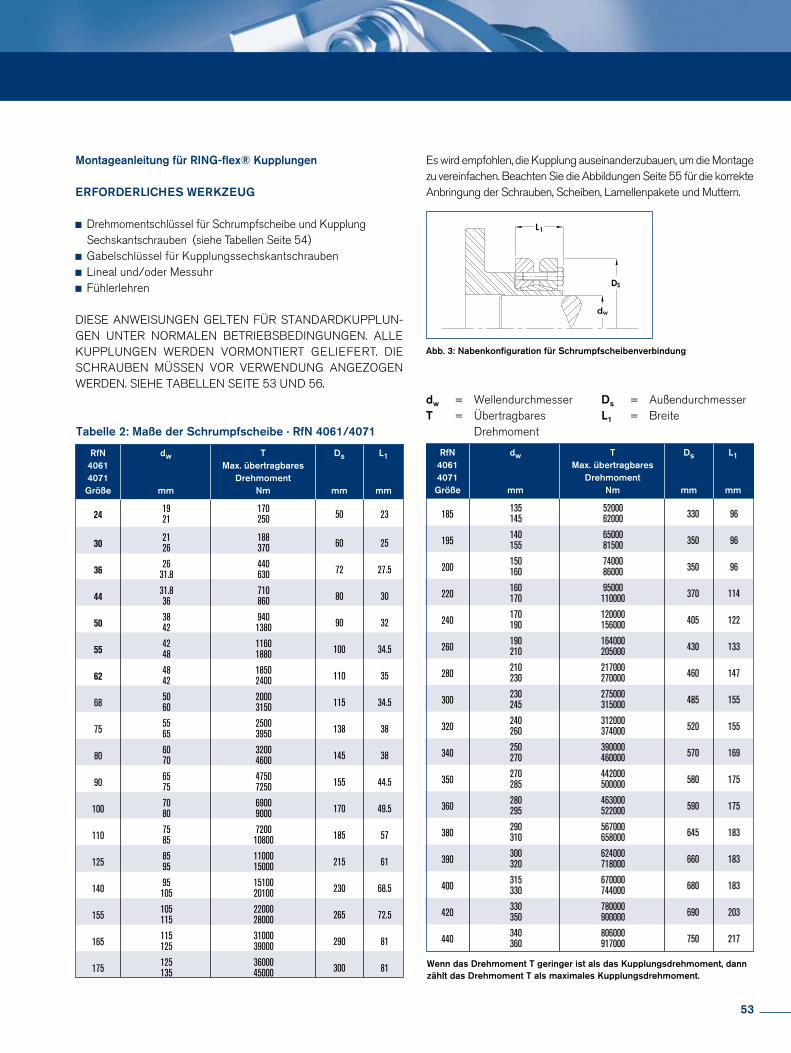
RfN dw T Ds L1 4061 Max. übertragbares 4071 Drehmoment Größe mm Nm mm mm
24
19 170 21 250 50 23
30
21 188 26 370 60 25
36
26 440 31.8 630 72 27.5
44
31.8 710 36 860 80 30
50
38 940 42 1380 90 32
55
42 1160 48 1880 100 34.5
62
48 1850 42 2400 110 35
68 50 2000 60 3150 115 34.5
75 55 2500 65 3950 138 38
80 60 3200 70 4600 145 38
90 65 4750 75 7250 155 44.5
100 70 6900 80 9000 170 49.5
110 75 7200 85 10800 185 57
125 85 11000 95 15000 215 61
140 95 15100 105 20100 230 68.5
155 105 22000 115 28000 265 72.5
165 115 31000 125 39000 290 81
175 125 36000 135 45000 300 81
RfN dw T Ds L1 4061 Max. übertragbares 4071 Drehmoment Größe mm Nm mm mm
185 135 52000 145 62000 330 96
195 140 65000 155 81500 350 96
200 150 74000 160 86000 350 96
220 160 95000 170 110000 370 114
240 170 120000 190 156000 405 122
260 190 164000 210 205000 430 133
280 210 217000 230 270000 460 147
300 230 275000 245 315000 485 155
320 240 312000 260 374000 520 155
340 250 390000 270 460000 570 169
350 270 442000 285 500000 580 175
360 280 463000 295 522000 590 175
380 290 567000 310 658000 645 183
390 300 624000 320 718000 660 183
400 315 670000 330 744000 680 183
420 330 780000 350 900000 690 203
440 340 806000 360 917000 750 217
Wenn das Drehmoment T geringer ist als das Kupplungsdrehmoment, dannzählt das Drehmoment T als maximales Kupplungsdrehmoment.
Tabelle 2: Maße der Schrumpfscheibe · RfN 4061/4071
Abb. 3: Nabenkonfiguration für Schrumpfscheibenverbindung
dw = WellendurchmesserT = Übertragbares Drehmoment
Ds = AußendurchmesserL1 = Breite
Montageanleitung für RING-flex® Kupplungen
ERFORDERLICHES WERKZEUG
Drehmomentschlüssel für Schrumpfscheibe und Kupplung Sechskantschrauben (siehe Tabellen Seite 54) Gabelschlüssel für Kupplungssechskantschrauben Lineal und/oder Messuhr Fühlerlehren
DIESE ANWEISUNGEN GELTEN FÜR STANDARDKUPPLUNGEN UNTER NORMALEN BETRIEBSBEDINGUNGEN. ALLE KUPPLUNGEN WERDEN VORMONTIERT GELIEFERT. DIE SCHRAUBEN MÜSSEN VOR VERWENDUNG ANGEZOGEN WERDEN. SIEHE TABELLEN SEITE 53 UND 56.
Es wird empfohlen, die Kupplung auseinanderzubauen, um die Montage zu vereinfachen. Beachten Sie die Abbildungen Seite 55 für die korrekte Anbringung der Schrauben, Scheiben, Lamellenpakete und Muttern.
53
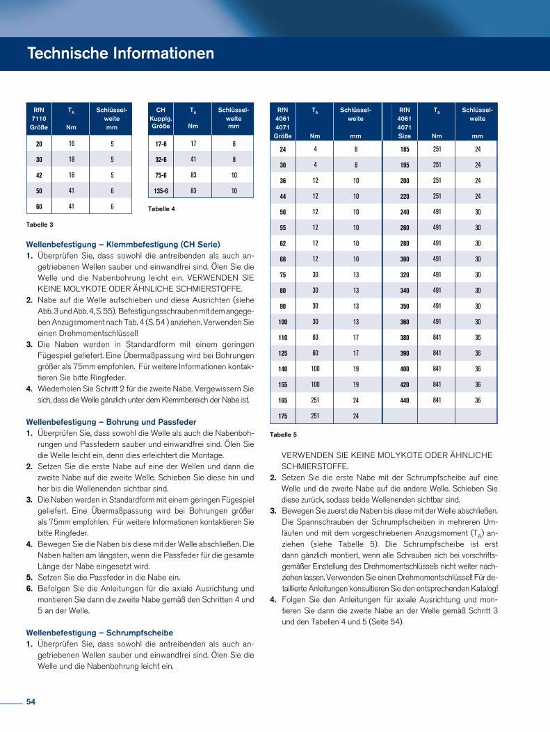
Technische Informationen
RfN TA Schlüssel- 7110 weite Größe Nm mm
20
5 16
30
5 18
42 5 18
50
6 41
60
6 41
CH TA Schlüssel- Kupplg. weite Größe Nm mm
17-6
6 17
32-6
8 41 75-6
10 83 135-6
10 83
Tabelle 3
Tabelle 4
Wellenbefestigung – Klemmbefestigung (CH Serie)1. Überprüfen Sie, dass sowohl die antreibenden als auch an getriebenen Wellen sauber und einwandfrei sind. Ölen Sie die Welle und die Nabenbohrung leicht ein. VERWENDEN SIE KEINE MOLYKOTE ODER ÄHNLICHE SCHMIERSTOFFE.2. Nabe auf die Welle aufschieben und diese Ausrichten (siehe Abb. 3 und Abb. 4, S. 55). Befestigungsschrauben mit dem angege ben Anzugsmoment nach Tab. 4 (S. 54 ) anziehen. Verwenden Sie einen Drehmomentschlüssel!3. Die Naben werden in Standardform mit einem geringen Fügespiel geliefert. Eine Übermaßpassung wird bei Bohrungen größer als 75mm empfohlen. Für weitere Informationen kontak tieren Sie bitte Ringfeder.4. Wiederholen Sie Schritt 2 für die zweite Nabe. Vergewissern Sie sich, dass die Welle gänzlich unter dem Klemmbereich der Nabe ist.
Wellenbefestigung – Bohrung und Passfeder1. Überprüfen Sie, dass sowohl die Welle als auch die Nabenboh rungen und Passfedern sauber und einwandfrei sind. Ölen Sie die Welle leicht ein, denn dies erleichtert die Montage.2. Setzen Sie die erste Nabe auf eine der Wellen und dann die zweite Nabe auf die zweite Welle. Schieben Sie diese hin und her bis die Wellenenden sichtbar sind.3. Die Naben werden in Standardform mit einem geringen Fügespiel geliefert. Eine Übermaßpassung wird bei Bohrungen größer als 75mm empfohlen. Für weitere Informationen kontaktieren Sie bitte Ringfeder.4. Bewegen Sie die Naben bis diese mit der Welle abschließen. Die Naben halten am längsten, wenn die Passfeder für die gesamte Länge der Nabe eingesetzt wird.5. Setzen Sie die Passfeder in die Nabe ein.6. Befolgen Sie die Anleitungen für die axiale Ausrichtung und montieren Sie dann die zweite Nabe gemäß den Schritten 4 und 5 an der Welle.
Wellenbefestigung – Schrumpfscheibe1. Überprüfen Sie, dass sowohl die antreibenden als auch an getriebenen Wellen sauber und einwandfrei sind. Ölen Sie die Welle und die Nabenbohrung leicht ein.
VERWENDEN SIE KEINE MOLYKOTE ODER ÄHNLICHE SCHMIERSTOFFE.2. Setzen Sie die erste Nabe mit der Schrumpfscheibe auf eine Welle und die zweite Nabe auf die andere Welle. Schieben Sie diese zurück, sodass beide Wellenenden sichtbar sind.3. Bewegen Sie zuerst die Naben bis diese mit der Welle abschließen. Die Spannschrauben der Schrumpfscheiben in mehreren Um läufen und mit dem vorgeschriebenen Anzugsmoment (TA) an ziehen (siehe Tabelle 5). Die Schrumpfscheibe ist erst dann gänzlich montiert, wenn alle Schrauben sich bei vorschrifts gemäßer Einstellung des Drehmomentschlüssels nicht weiter nach ziehen lassen. Verwenden Sie einen Drehmomentschlüssel! Für de taillierte Anleitungen konsultieren Sie den entsprechenden Katalog! 4. Folgen Sie den Anleitungen für axiale Ausrichtung und mon tieren Sie dann die zweite Nabe an der Welle gemäß Schritt 3 und den Tabellen 4 und 5 (Seite 54).
RfN TA Schlüssel- 4061 weite 4071 Größe Nm mm
24
8 4
30
8 4
36 10 12
44
10 12
50
10 12
55
10 12
62
10 12
68
10 12
75
13 30
80
13 30
90
13 30
100
13 30
110
17 60
125 17 60
140 19 100
155 19 100
165 24 251
175 24 251
RfN TA Schlüssel- 4061 weite 4071 Size Nm mm
185
24 251
195 24 251
200 24 251
220 24 251
240 30 491
260 30 491
280 30 491
300 30 491
320 30 491
340 30 491
350 30 491
360 30 491
380 36 841
390 36 841
400 36 841
420 36 841
440 36 841
Tabelle 5
54
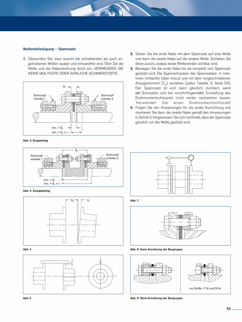
Abb. 3: Eingelenkig
Abb. 7
Abb. 8: Serie Anordnung der Baugruppe
Abb. 9: Serie Anordnung der Baugruppe
Abb. 4: Zweigelenkig
Abb. 5
Abb. 6
nur Größe 17-6 und 32-6
S1 U
Schrumpf-scheibe 2
Schrumpf-scheibe 1
min. = S2
min. = S2 + x
S1
Schrumpf-scheibe 2
Schrumpf-scheibe 1
min. = S2
min. = S2 + x
S2
Wellenbefestigung – Spannsatz
1. Überprüfen Sie, dass sowohl die antreibenden als auch an getriebenen Wellen sauber und einwandfrei sind. Ölen Sie die Welle und die Nabenbohrung leicht ein. VERWENDEN SIE KEINE MOLYKOTE ODER ÄHNLICHE SCHMIERSTOFFE.
2. Setzen Sie die erste Nabe mit dem Spannsatz auf eine Welle und dann die zweite Nabe auf die andere Welle. Schieben Sie diese zurück, sodass beide Wellenenden sichtbar sind.3. Bewegen Sie die erste Nabe bis sie komplett vom Spannsatz gestützt wird. Die Spannschrauben des Spannsatzes in meh reren Umläufen (über kreuz) und mit dem vorgeschriebenen Anzugsmoment (TA) anziehen (siehe Tabelle 3, Seite 54). Der Spannsatz ist erst dann gänzlich montiert, wenn alle Schrauben sich bei vorschriftsgemäßer Einstellung des Drehmomentschlüssels nicht weiter nachziehen lassen. Verwenden Sie einen Drehmomentschlüssel ! 4. Folgen Sie den Anweisungen für die axiale Ausrichtung und montieren Sie dann die zweite Nabe gemäß den Anweisungen in Schritt 3. Vergewissern Sie sich nochmals, dass der Spannsatz gänzlich von der Welle gestützt wird.
55
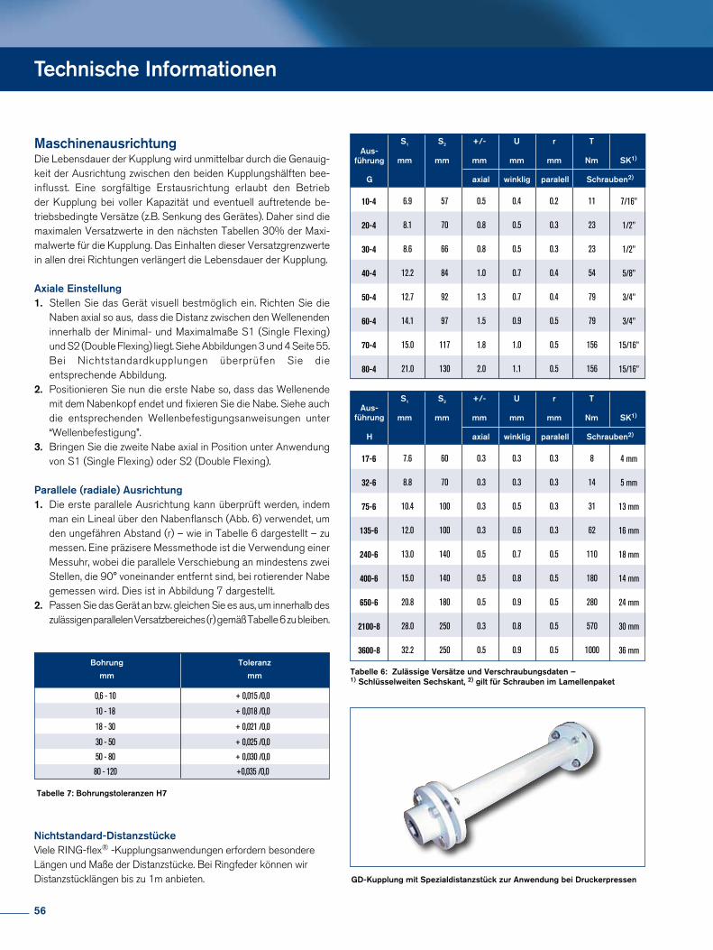
MaschinenausrichtungDie Lebensdauer der Kupplung wird unmittelbar durch die Genauigkeit der Ausrichtung zwischen den beiden Kupplungshälften beeinflusst. Eine sorgfältige Erstausrichtung erlaubt den Betrieb der Kupplung bei voller Kapazität und eventuell auftretende betriebsbedingte Versätze (z.B. Senkung des Gerätes). Daher sind die maximalen Versatzwerte in den nächsten Tabellen 30% der Maximalwerte für die Kupplung. Das Einhalten dieser Versatzgrenzwerte in allen drei Richtungen verlängert die Lebensdauer der Kupplung.
Axiale Einstellung1. Stellen Sie das Gerät visuell bestmöglich ein. Richten Sie die Naben axial so aus, dass die Distanz zwischen den Wellenenden innerhalb der Minimal und Maximalmaße S1 (Single Flexing) und S2 (Double Flexing) liegt. Siehe Abbildungen 3 und 4 Seite 55. Bei Nichtstandardkupplungen überprüfen Sie die entsprechende Abbildung.2. Positionieren Sie nun die erste Nabe so, dass das Wellenende mit dem Nabenkopf endet und fixieren Sie die Nabe. Siehe auch die entsprechenden Wellenbefestigungsanweisungen unter “Wellenbefestigung”.3. Bringen Sie die zweite Nabe axial in Position unter Anwendung von S1 (Single Flexing) oder S2 (Double Flexing).
Parallele (radiale) Ausrichtung1. Die erste parallele Ausrichtung kann überprüft werden, indem man ein Lineal über den Nabenflansch (Abb. 6) verwendet, um den ungefähren Abstand (r) – wie in Tabelle 6 dargestellt – zu messen. Eine präzisere Messmethode ist die Verwendung einer Messuhr, wobei die parallele Verschiebung an mindestens zwei Stellen, die 90° voneinander entfernt sind, bei rotierender Nabe gemessen wird. Dies ist in Abbildung 7 dargestellt.2. Passen Sie das Gerät an bzw. gleichen Sie es aus, um innerhalb des zulässigen parallelen Versatzbereiches (r) gemäß Tabelle 6 zu bleiben.
S1 S2 +/- U r T mm mm mm mm mm Nm SK1)
G axial winklig paralell Schrauben2)
Aus-führung
10-4 7/16” 6.9 57 0.5 0.4 0.2 11
20-4
1/2” 8.1 70 0.8 0.5 0.3 23
30-4
1/2” 8.6 66 0.8 0.5 0.3 23
40-4
5/8” 12.2 84 1.0 0.7 0.4 54
50-4
3/4” 12.7 92 1.3 0.7 0.4 79
60-4
3/4” 14.1 97 1.5 0.9 0.5 79
70-4
15/16” 15.0 117 1.8 1.0 0.5 156
80-4
15/16” 21.0 130 2.0 1.1 0.5 156
S1 S2 +/- U r T mm mm mm mm mm Nm SK1)
H axial winklig paralell Schrauben2)
17-6
4 mm 7.6 60 0.3 0.3 0.3 8
32-6
5 mm 8.8 70 0.3 0.3 0.3 14
75-6
13 mm 10.4 100 0.3 0.5 0.3 31
135-6
16 mm 12.0 100 0.3 0.6 0.3 62
240-6
18 mm 13.0 140 0.5 0.7 0.5 110
400-6
14 mm 15.0 140 0.5 0.8 0.5 180
650-6
24 mm 20.8 180 0.5 0.9 0.5 280
2100-8
30 mm 28.0 250 0.3 0.8 0.5 570
3600-8
36 mm 32.2 250 0.5 0.9 0.5 1000
Tabelle 6: Zulässige Versätze und Verschraubungsdaten –1) Schlüsselweiten Sechskant, 2) gilt für Schrauben im Lamellenpaket
Tabelle 7: Bohrungstoleranzen H7
Bohrung Toleranz
mm mm
0,6 - 10 + 0,015 /0,0
10 - 18 + 0,018 /0,0
18 - 30 + 0,021 /0,0
30 - 50 + 0,025 /0,0
50 - 80 + 0,030 /0,0
80 - 120 +0,035 /0,0
GD-Kupplung mit Spezialdistanzstück zur Anwendung bei Druckerpressen
Technische Informationen
Nichtstandard-Distanzstücke Viele RINGflex® Kupplungsanwendungen erfordern besondere Längen und Maße der Distanzstücke. Bei Ringfeder können wir Distanzstücklängen bis zu 1m anbieten.
Aus-führung
56
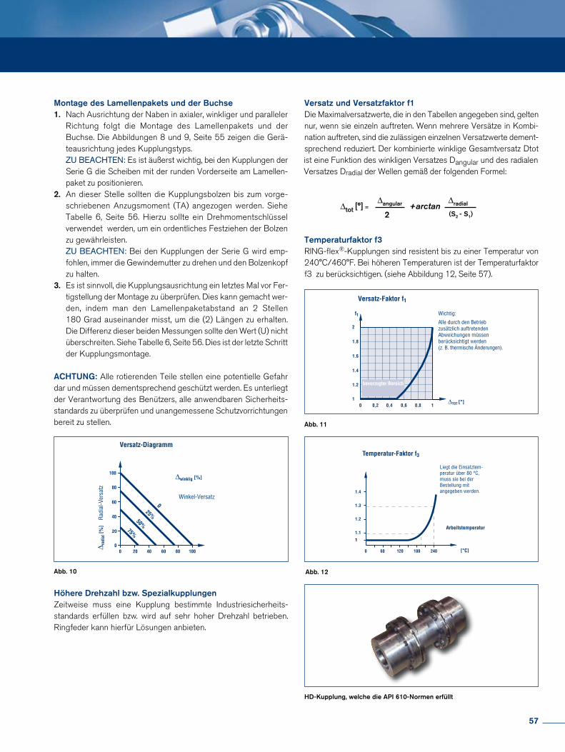
1
1.2
1.4
1.6
1.8
2
f1
Versatz und Versatzfaktor f1Die Maximalversatzwerte, die in den Tabellen angegeben sind, gelten nur, wenn sie einzeln auftreten. Wenn mehrere Versätze in Kombination auftreten, sind die zulässigen einzelnen Versatzwerte dementsprechend reduziert. Der kombinierte winklige Gesamtversatz Dtot
∆tot [°] = +arctan∆angular
2
∆radial
(S2 - S1)
Temperaturfaktor f3RINGflex®Kupplungen sind resistent bis zu einer Temperatur von 240°C/460°F. Bei höheren Temperaturen ist der Temperaturfaktor f3 zu berücksichtigen. (siehe Abbildung 12, Seite 57).
Höhere Drehzahl bzw. SpezialkupplungenZeitweise muss eine Kupplung bestimmte Industriesicherheitsstandards erfüllen bzw. wird auf sehr hoher Drehzahl betrieben. Ringfeder kann hierfür Lösungen anbieten.
ist eine Funktion des winkligen Versatzes Dangular und des radialen Versatzes Dradial der Wellen gemäß der folgenden Formel:
Montage des Lamellenpakets und der Buchse1. Nach Ausrichtung der Naben in axialer, winkliger und paralleler Richtung folgt die Montage des Lamellenpakets und der Buchse. Die Abbildungen 8 und 9, Seite 55 zeigen die Gerä teausrichtung jedes Kupplungstyps. ZU BEACHTEN: Es ist äußerst wichtig, bei den Kupplungen der Serie G die Scheiben mit der runden Vorderseite am Lamellen paket zu positionieren.2. An dieser Stelle sollten die Kupplungsbolzen bis zum vorge schriebenen Anzugsmoment (TA) angezogen werden. Siehe Tabelle 6, Seite 56. Hierzu sollte ein Drehmomentschlüssel verwendet werden, um ein ordentliches Festziehen der Bolzen zu gewährleisten. ZU BEACHTEN: Bei den Kupplungen der Serie G wird emp fohlen, immer die Gewindemutter zu drehen und den Bolzenkopf zu halten.3. Es ist sinnvoll, die Kupplungsausrichtung ein letztes Mal vor Fer tigstellung der Montage zu überprüfen. Dies kann gemacht wer den, indem man den Lamellenpaketabstand an 2 Stellen 180 Grad auseinander misst, um die (2) Längen zu erhalten. Die Differenz dieser beiden Messungen sollte den Wert (U) nicht überschreiten. Siehe Tabelle 6, Seite 56. Dies ist der letzte Schritt der Kupplungsmontage.
ACHTUNG: Alle rotierenden Teile stellen eine potentielle Gefahr dar und müssen dementsprechend geschützt werden. Es unterliegt der Verantwortung des Benützers, alle anwendbaren Sicherheitsstandards zu überprüfen und unangemessene Schutzvorrichtungen bereit zu stellen.
1
1.2
1.4
1.6
1.8
2
f1
Abb. 11
Abb. 12Abb. 10
HD-Kupplung, welche die API 610-Normen erfüllt
57
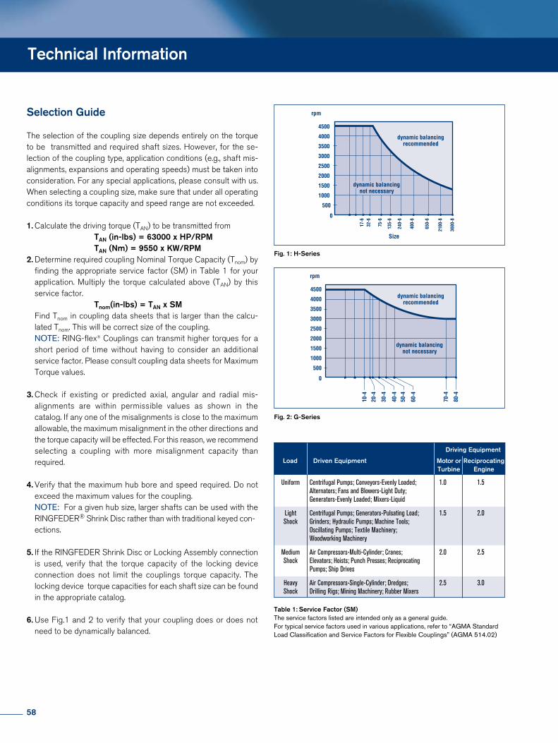
Technical Information
Selection Guide
The selection of the coupling size depends entirely on the torque to be transmitted and required shaft sizes. However, for the selection of the coupling type, application conditions (e.g., shaft misalignments, expansions and operating speeds) must be taken into consideration. For any special applications, please consult with us. When selecting a coupling size, make sure that under all operating conditions its torque capacity and speed range are not exceeded.
1. Calculate the driving torque (TAN) to be transmitted from TAN (in-lbs) = 63000 x HP/RPM TAN (Nm) = 9550 x KW/RPM2. Determine required coupling Nominal Torque Capacity (Tnom) by finding the appropriate service factor (SM) in Table 1 for your application. Multiply the torque calculated above (TAN) by this service factor. Tnom(in-lbs) = TAN x SM Find Tnom in coupling data sheets that is larger than the calcu lated Tnom. This will be correct size of the coupling. NOTE: RINGflex® Couplings can transmit higher torques for a short period of time without having to consider an additional service factor. Please consult coupling data sheets for Maximum Torque values.
3. Check if existing or predicted axial, angular and radial mis alignments are within permissible values as shown in the catalog. If any one of the misalignments is close to the maximum allowable, the maximum misalignment in the other directions and the torque capacity will be effected. For this reason, we recommend selecting a coupling with more misalignment capacity than required.
4. Verify that the maximum hub bore and speed required. Do not exceed the maximum values for the coupling. NOTE: For a given hub size, larger shafts can be used with the RINGFEDER® Shrink Disc rather than with traditional keyed con ections.
5. If the RINGFEDER Shrink Disc or Locking Assembly connection is used, verify that the torque capacity of the locking device connection does not limit the couplings torque capacity. The locking device torque capacities for each shaft size can be found in the appropriate catalog.
6. Use Fig.1 and 2 to verify that your coupling does or does not need to be dynamically balanced.
Table 1: Service Factor (SM)The service factors listed are intended only as a general guide.For typical service factors used in various applications, refer to “AGMA StandardLoad Classification and Service Factors for Flexible Couplings” (AGMA 514.02)
Fig. 1: H-Series
Fig. 2: G-Series
Driving Equipment
Load Driven Equipment Motor or Reciprocating Turbine Engine
Uniform Centrifugal Pumps; Conveyors-Evenly Loaded; 1.0 1.5 Alternators; Fans and Blowers-Light Duty; Generators-Evenly Loaded; Mixers-Liquid
Light Centrifugal Pumps; Generators-Pulsating Load; 1.5 2.0 Shock Grinders; Hydraulic Pumps; Machine Tools; Oscillating Pumps; Textile Machinery; Woodworking Machinery
Medium Air Compressors-Multi-Cylinder; Cranes; 2.0 2.5 Shock Elevators; Hoists; Punch Presses; Reciprocating Pumps; Ship Drives
Heavy Air Compressors-Single-Cylinder; Dredges; 2.5 3.0 Shock Drilling Rigs; Mining Machinery; Rubber Mixers
58
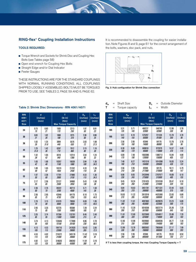
If T is less than coupling torque, the max Coupling Torque Capacity = T
Table 2: Shrink Disc Dimensions · RfN 4061/4071
Fig. 3: Hub configuration for Shrink Disc connection
dw = Shaft SizeT = Torque capacity
Ds = Outside DiameterL1 = Width
RING-flex® Coupling Installation Instructions TOOLS REQUIRED:
Torque Wrench and Sockets for Shrink Disc and Coupling Hex Bolts (see Tables page 58) Open end wrench for Coupling Hex Bolts Straight Edge and/or Dial Indicator Feeler Gauges
THESE INSTRUCTIONS ARE FOR THE STANDARD COUPLINGS WITH NORMAL RUNNING CONDITIONS. ALL COUPLINGS SHIPPED LOOSELY ASSEMBLED. BOLTS MUST BE TORQUED PRIOR TO USE. SEE TABLES 2, PAGE 59 AND 6, PAGE 62.
It is recommended to disassemble the coupling for easier installation. Note Figures 8 and 9, page 61 for the correct arrangement of the bolts, washers, disc pack, and nuts.
RfN d T Ds L1 4061 (inches) (lb-in) (inches) (inches) 4071 (mm) (Nm) (mm) (mm) Size Max Torque Capacity
24
0.75 0.83 1505 2213 1.97 0.91 19 21 170 250 50 23
30
0.83 1.02 1668 3275 2.36 0.98 21 26 188 370 60 25
36
1.02 1.25 3894 5576 2.83 1.08 26 31.8 440 630 72 27.5
44
1.25 1.42 6287 7612 3.15 1.16 31.8 36 710 860 80 30
50
1.42 1.65 8316 12214 3.54 1.24 38 42 940 1380 90 32
55
1.65 1.89 10267 16639 3.94 1.36 42 48 1160 1880 100 34.5
62
1.89 1.65 16374 21242 4.33 1.36 48 42 1850 2400 110 35
68 1.97 2.36 17701 27880 4.53 1.36 50 60 2000 3150 115 34.5
75
2.17 2.56 22127 34960 5.43 1.50 55 65 2500 3950 138 38
80
2.36 2.76 28322 40713 5.71 1.50 60 70 3200 4600 145 38
90
2.56 2.95 42048 64176 6.10 1.75 65 75 4750 7250 155 44.5
100 2.76 3.15 61070 79656 6.69 1.95
70 80 6900 9000 170 49.5
110
2.95 3.35 63725 95588 7.28 2.24 75 85 7200 10800 185 57
125
3.35 3.74 97358 132761 8.46 2.40 85 95 11000 15000 215 61
140 3.74 4.13 133646 177899 9.06 2.70
95 105 15100 20100 230 68.5
155
4.13 4.53 194716 247820 10.43 2.85 105 115 22000 28000 265 72.5
165
4.53 4.92 274372 345178 11.42 3.19 115 125 31000 39000 290 81
175
4.92 5.31 318626 398282 11.81 3.19 125 135 36000 45000 300 81
RfN dw T Ds L 4061 (inches) (lb-in) (inches) (inches) 4071 (mm) (Nm) (mm) (mm) Size Max Torque Capacity
185 5.31 5.71 460237 548745 12.99 3.78 135 145 52000 62000 330 96
195 5.51 6.10 575297 721334 13.78 3.78 140 155 65000 81500 350 96
200 2.56 2.95 42048 64176 13.78 3.78
150 160 74000 86000 350 96
220 6.30 6.69 840818 973579 14.57 4.49 160 170 95000 110000 370 114
240 6.69 7.48 1062086 1380712 15.94 4.80 170 190 120000 156000 405 122
260 7.48 8.27 1451518 1814398 16.93 5.24 190 210 164000 205000 430 133
280 2.56 2.95 42048 64176 18.11 5.79 210 230 217000 270000 460 147
300 9.06 9.65 2433948 2787977 19.09 6.10 230 245 275000 315000 485 155
320 9.45 10.24 2761425 3310169 20.47 6.10 240 260 312000 374000 520 155
340 9.84 10.63 3451781 4071331 22.44 6.65 250 270 390000 460000 570 169
350 10.63 11.22 3912018 4425360 22.83 6.89 270 285 442000 500000 580 175
360 11.02 11.61 4097883 4620076 23.23 6.89 280 295 463000 522000 590 175
380 11.42 12.20 5018358 5823774 25.39 7.20 290 310 567000 658000 645 183
390 11.81 12.60 5522849 6354817 25.98 7.20 300 320 624000 718000 660 183
400 12.40 12.99 5929982 6584936 26.77 7.20 315 330 670000 744000 680 183
420 12.99 13.78 6903562 7965648 27.17 7.99 330 350 780000 900000 690 203
440 2.56 2.95 42048 64176 29.53 8.54 340 360 806000 917000 750 217
59
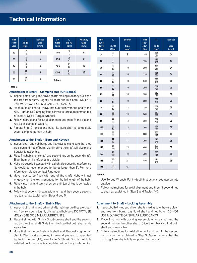
Attachment to Shaft – Clamping Hub (CH Series)1. Inspect both driving and driven shafts making sure they are clean and free from burrs. Lightly oil shaft and hub bore. DO NOT USE MOLYKOTE OR SIMILAR LUBRICANTS.2. Place hubs on shafts. Move first hub flush with the end of the hub. Tighten all Clamping Hub screws to torque recommended in Table 4. Use a Torque Wrench!3. Follow instructions for axial alignment and then fit the second hub as explained in Step 4.4. Repeat Step 2 for second hub. Be sure shaft is completely under clamping portion of hub.
Attachment to the Shaft – Bore and Keyway1. Inspect shaft and hub bores and keyways to make sure that they are clean and free of burrs. Lightly oiling the shaft will also make it easier to assemble.2. Place first hub on one shaft and second hub on the second shaft. Slide them until shaft ends are visible.3. Hubs are supplied standard with a slight clearance fit. Interference fits would be recommended for bores larger than 3”. For more information, please contact Ringfeder.4. Move hubs to be flush with end of the shaft. Hubs will last longest when the key is engaged for the full length of the hub. 5. Fit key into hub and turn set screw until top of key is contacted in the hub. 6. Follow instructions for axial alignment and then secure second hub to shaft as explained in Steps 4 and 5.
Attachment to the Shaft – Shrink Disc1. Inspect both driving and driven shafts making sure they are clean and free from burrs. Lightly oil shaft and hub bore. DO NOT USE MOLYKOTE OR SIMILAR LUBRICANTS.2. Place first hub with Shrink Disc® on one shaft and the second hub on the other shaft. Slide them back so that both shaft ends are visible.3. Move first hub to be flush with shaft end. Gradually tighten all Shrink Disc locking screws, in several passes, to specified tightening torque (TA); see Table 5. Shrink Disc is not fully installed until one pass is completed without any bolts turning.
Use Torque Wrench! For indepth instructions, see appropriate catalog.4. Follow instructions for axial alignment and then fit second hub to shaft as explained in Step 3 and Tables 45.
Attachment to Shaft – Locking Assembly1. Inspect both driving and driven shafts making sure they are clean and free from burrs. Lightly oil shaft and hub bore. DO NOT USE MOLYKOTE OR SIMILAR LUBRICANTS.2. Place first hub with Locking Assembly on one shaft and the second hub on the other shaft. Slide them back so that both shaft ends are visible.3. Follow instructions for axial alignment and then fit the second hub to shaft as explained in Step 3. Again, be sure that the Locking Assembly is fully supported by the shaft.
Technical Information
Table 3
Table 4
RfN TA Socket 7110 (lb-ft) Size Size (Nm) (mm)
20
12 5 16
30
13 5 18
42
13 5 18
50
30 6 41
60
30 6 41
CH TA Hex key Cplg (lb-ft) Size Size (Nm) (mm)
17-6
13 6 17
32-6
30 8 41
75-6
61 10 83
135-6
61 10 83
RfN TA Socket 4061 4071 (lb-ft) Size Size (Nm) (mm)
24
3 8 4
30
3 8 4
36
9 10 12
44
9 10 12
50
9 10 12
55
9 10 12
62
9 10 12
68
9 10 12
75
22 13 30
80
22 13 30
90
22 13 30
100
22 13 30
110
44 17 60
125 44 17 60
140 74 19 100
155 74 19 100
165 185 24 251
175 185 24 251
RfN TA Socket 4061 4071 (lb-ft) Size Size (Nm) (mm)
185
185 24 251
195 185 24 251
200 185 24 251
220 185 24 251
240 362 30 491
260 362 30 491
280 362 30 491
300 362 30 491
320 362 30 491
340 362 30 491
350 362 30 491
360 362 30 491
380 620 36 841
390 620 36 841
400 620 36 841
420 620 36 841
440 620 36 841
Table 5
60
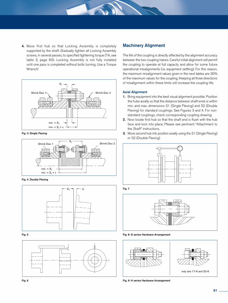
Fig. 3: Single Flexing
Fig. 7
Fig. 8: G series Hardware Arrangement
Fig. 9: H series Hardware Arrangement
Fig. 4: Double Flexing
Fig. 5
Fig. 6
only size 17-6 and 32-6
S1 U
Shrink Disc 2Shrink Disc 1
min. = S2
min. = S2 + x
S1
Shrink Disc 2Shrink Disc 1
min. = S2
min. = S2 + x
S2
4. Move first hub so that Locking Assembly is completely supported by the shaft. Gradually tighten all Locking Assembly screws, in several passes, to specified tightening torque (TA, see table 3, page 60). Locking Assembly is not fully installed until one pass is completed without bolts turning. Use a Torque Wrench!
Machinery Alignment
The life of the coupling is directly affected by the alignment accuracy between the two coupling halves. Careful initial alignment will permit the coupling to operate at full capacity and allow for some future operational misalignments (i.e. equipment settling). For this reason, the maximum misalignment values given in the next tables are 30% of the maximum values for the coupling. Keeping all three directions of misalignment within these limits will increase the coupling life.
Axial Alignment1. Bring equipment into the best visual alignment possible. Position the hubs axially so that the distance between shaft ends is within min. and max. dimensions S1 (Single Flexing) and S2 (Double Flexing) for standard couplings. See Figures 3 and 4. For non standard couplings, check corresponding coupling drawing.2. Now locate first hub so that the shaft end is flush with the hub face and lock into place. Please see pertinent “Attachment to the Shaft” instructions.3. Move second hub into position axially using the S1 (Single Flexing) or S2 (Double Flexing)
61
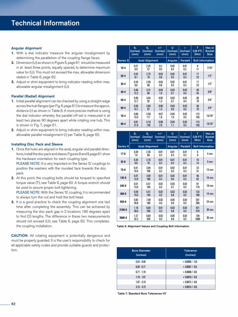
Angular Alignment1. With a dial indicator measure the angular misalignment by determining the parallelism of the coupling flange faces.2. Dimension (U) as shown in Figure 5, page 61 should be measured in at least three points, equally spaced, to determine maximum value for (U). This must not exceed the max. allowable dimension stated in Table 6, page 62.3. Adjust or shim equipment to bring indicator reading within max. allowable angular misalignment (U).
Parallel (Radial) Alignment1. Initial parallel alignment can be checked by using a straightedge across the hub flanges (per Fig. 6, page 61) to measure the approx. distance (r) as shown in Table 6. A more precise method is using the dial indicator whereby the parallel offset is measured in at least two places 90 degrees apart while rotating one hub. This is shown in Fig. 7, page 61. 2. Adjust or shim equipment to bring indicator reading within max. allowable parallel misalignment (r) per Table 6, page 62.
Installing Disc Pack and Sleeve1. Once the hubs are aligned in the axial, angular and parallel direc tions, install the disc pack and sleeve. Figures 8 and 9, page 61 show the hardware orientation for each coupling type. PLEASE NOTE: It is very important on the Series ‘G’ couplings to position the washers with the rounded face towards the disc pack.2. At this point, the coupling bolts should be torqued to specified torque value (T); see Table 6, page 62. A torque wrench should be used to assure proper bolt tightening. PLEASE NOTE: With the Series ‘G’ coupling, it is recommended to always turn the nut and hold the bolt head.3. It is a good practice to check the coupling alignment one last time after completing the assembly. This can be achieved by measuring the disc pack gap in 2 locations 180 degrees apart to find (2) lengths. The difference in these two measurements should not exceed (U); see Table 6, page 62. This completes the coupling installation.
CAUTION: All rotating equipment is potentially dangerous and must be properly guarded. It is the user’s responsibility to check for all applicable safety codes and provide suitable guards and protection.
Table 6: Alignment Values and Coupling Bolt Information
Table 7: Standard Bore Tolerances H7
Technical Information
S1 S2 +/- U r T Hex or (inches) (inches) (inches) (inches) (inches) (LB-FT) Socket (mm) (mm) (mm) (mm) (mm) (Nm) Size
Series G Axial Alignment Angular Paralell Bolt Information
10-4 0.27 2.25 0.2 0.02 0.01 8 7/16” 6.9 57 0.5 0.4 0.2 11
20-4
0.32 2.75 0.03 0.02 0.01 17 1/2” 8.1 70 0.8 0.5 0.3 23
30-4
0.34 2.59 0.03 0.02 0.01 17 1/2” 8.6 66 0.8 0.5 0.3 23
40-4
0.48 3.31 0.04 0.03 0.02 40 5/8” 12.2 84 1.0 0.7 0.4 54
50-4
0.50 3.64 0.05 0.03 0.02 58 3/4” 12.7 92 1.3 0.7 0.4 79
60-4
0.56 3.83 0.06 0.03 0.02 58 3/4” 14.1 97 1.5 0.9 0.5 79
70-4
0.60 4.59 0.07 0.04 0.02 115 15/16” 15.0 117 1.8 1.0 0.5 156
80-4
0.81 5.10 0.08 0.04 0.02 115 15/16” 21.0 130 2.0 1.1 0.5 156
S1 S2 +/- U r T Hex or (inches) (inches) (inches) (inches) (inches) (LB-FT) Socket (mm) (mm) (mm) (mm) (mm) (Nm) Size
Series H Axial Alignment Angular Paralell Bolt Information
17-6
0.30 2.36 0.01 0.01 0.01 6 4 mm 7.6 60 0.3 0.3 0.3 8
32-6
0.35 2.76 0.01 0.01 0.01 10 5 mm 8.8 70 0.3 0.3 0.3 14
75-6
0.41 3.94 0.01 0.02 0.01 23 13 mm 10.4 100 0.3 0.5 0.3 31
135-6
0.47 3.94 0.01 0.02 0.01 46 16 mm 12.0 100 0.3 0.6 0.3 62
240-6
0.51 5.51 0.02 0.03 0.02 81 18 mm 13.0 140 0.5 0.7 0.5 110
400-6
0.59 5.51 0.02 0.03 0.02 133 14 mm 15.0 140 0.5 0.8 0.5 180
650-6
0.82 7.09 0.02 0.04 0.02 207 24 mm 20.8 180 0.5 0.9 0.5 280
2100-8
1.10 9.84 0.01 0.03 0.02 421 30 mm 28.0 250 0.3 0.8 0.5 570
3600-8
1.27 9.83 0.02 0.04 0.02 739 36 mm 32.2 250 0.5 0.9 0.5 1000
Bore Diameter Tolerance
(inches) (inches)
0.24 - 0.40 + 0.0006 / - 0.0
0.40 - 0.71 + 0.0007 / -0.0
0.71 - 1,19 + 0.0008 / -0.0
1.19 - 1.97 + 0.0010 / -0.0
1.97 - 3.15 + 0.0012 / -0.0
3.15 - 4.73 + 0.0014 / -0.0
62
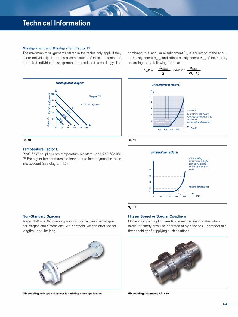
GD coupling with special spacer for printing press application HD coupling that meets API 610
Technical Information
1
1.2
1.4
1.6
1.8
2
f1
1
1.2
1.4
1.6
1.8
2
f1
Misalignment and Misalignment Factor f1The maximum misalignments stated in the tables only apply if they occur individually. If there is a combination of misalignments, the permitted individual misalignments are reduced accordingly. The
∆tot [°] = +arctan∆angular
2
∆radial
(S2 - S1)
Temperature Factor f3
RINGflex® couplings are temperatureresistant up to 240 °C/460 °F. For higher temperatures the temperature factor f3 must be taken into account (see diagram 12).
combined total angular misalignment Dtot is a function of the angular misalignment ∆angular and offset misalignment ∆radial of the shafts, according to the following formula:
Non-Standard Spacers Many RINGflex(R) coupling applications require special spacer lengths and dimensions. At Ringfeder, we can offer spacer lengths up to 1m long.
Higher Speed or Special Couplings Occasionally a coupling needs to meet certain industrial standards for safety or will be operated at high speeds. Ringfeder has the capability of supplying such solutions.
Fig. 10 Fig. 11
Fig. 12
63
Notizen · Notes
64

Notizen · Notes
65
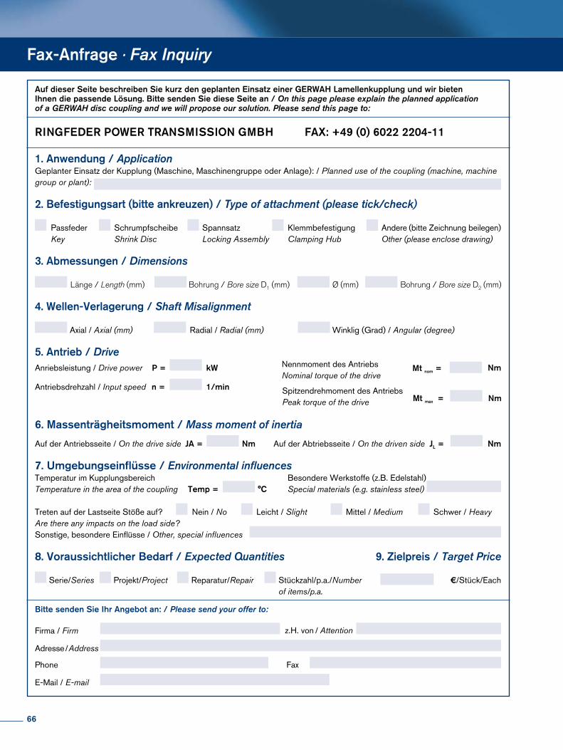
Auf dieser Seite beschreiben Sie kurz den geplanten Einsatz einer GERWAH Lamellenkupplung und wir bieten Ihnen die passende Lösung. Bitte senden Sie diese Seite an / On this page please explain the planned application of a GERWAH disc coupling and we will propose our solution. Please send this page to:
3. Abmessungen / Dimensions
Länge / Length (mm) Bohrung / Bore size D1 (mm) Bohrung / Bore size D2 (mm)Ø (mm)
4. Wellen-Verlagerung / Shaft Misalignment
Axial / Axial (mm) Radial / Radial (mm) Winklig (Grad) / Angular (degree)
2. Befestigungsart (bitte ankreuzen) / Type of attachment (please tick/check)
Passfeder Key
Klemmbefestigung Clamping Hub
Spannsatz Locking Assembly
Andere (bitte Zeichnung beilegen) Other (please enclose drawing)
Schrumpfscheibe Shrink Disc
Bitte senden Sie Ihr Angebot an: / Please send your offer to:
8. Voraussichtlicher Bedarf / Expected Quantities
Serie/Series Projekt/Project Reparatur/Repair Stückzahl/p.a./Number of items/p.a.
Nein / No Leicht / Slight Mittel / Medium Schwer / HeavyTreten auf der Lastseite Stöße auf? Are there any impacts on the load side?
Firma / Firm
Adresse / Address
Phone
E-Mail / E-mail
Fax
z.H. von / Attention
7. Umgebungseinflüsse / Environmental influencesTemperatur im Kupplungsbereich Temperature in the area of the coupling
Besondere Werkstoffe (z.B. Edelstahl) Special materials (e.g. stainless steel)Temp = °C
9. Zielpreis / Target Price
€/Stück/Each
6. Massenträgheitsmoment / Mass moment of inertia
Auf der Antriebsseite / On the drive side Auf der Abtriebsseite / On the driven side JA =
Fax-Anfrage · Fax Inquiry
Nm JL = Nm
1. Anwendung / ApplicationGeplanter Einsatz der Kupplung (Maschine, Maschinengruppe oder Anlage): / Planned use of the coupling (machine, machine group or plant):
Anriebsleistung / Drive power P = kW
Antriebsdrehzahl / Input speed n = 1/min
Nennmoment des AntriebsNominal torque of the drive
Mt nom = Nm
Mt maxx =Spitzendrehmoment des AntriebsPeak torque of the drive Nm
5. Antrieb / Drive
Sonstige, besondere Einflüsse / Other, special influences
RINGFEDER POWER TRANSMISSION GMBH FAX: +49 (0) 6022 2204-11
66
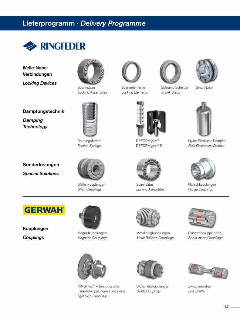
Lieferprogramm · Delivery Programme
Welle-Nabe- Verbindungen
Locking DevicesSpannsätzeLocking Assemblies
SpannelementeLocking Elements
SchrumpfscheibenShrink Discs
Dämpfungstechnik
Damping Technology
ReibungsfedernFriction Springs
DEFORM plus®
DEFORM plus® RHydro Elastische DämpferFluid Elastomeric Damper
Sonderlösungen
Special Solutions
Kupplungen
CouplingsMagnetkupplungenMagnetic Couplings
ElastomerkupplungenServo-Insert Couplings
SicherheitskupplungenSafety Couplings
RING-flex® – torsionssteife Lamellenkupplungen / torsionallyrigid Disc Couplings
SpannsätzeLocking Assemblies
FlanschkupplungenFlange Couplings
ZwischenwellenLine Shafts
Smart-Lock
WellenkupplungenShaft Couplings
MetallbalgkupplungenMetal Bellows Couplings
67
RINGFEDER POWER TRANSMISSION GMBH• Oberschlesienstr.15,D-47807Krefeld,Germany·Phone:+49(0)2151835-232·Fax:+49(0)2151835-19232 E-mail:[email protected]• LützeltalerStr.5a,D-63868Großwallstadt,Germany·Phone:+49(0)60222204-0·Fax:+49(0)60222204-11 E-mail:[email protected]
RINGFEDER POWER TRANSMISSION INDIA PRIVATE LIMITEDPlotNo.4,DoorNo.220,Mount-PoonamalleeRoad,Kattupakkam,Chennai–600056,IndiaPhone:+91(0)44-2649-6411·Fax:+91(0)44-2649-6422·E-mail:[email protected]·E-mail:[email protected]
RINGFEDER POWER TRANSMISSION USA CORPORATION165CarverAvenue,P.O.Box691Westwood,NJ07675,USA·TollFree:+1888746-4333·Phone:+12016663320Fax:+12016646053·E-mail:[email protected]·E-mail:[email protected]
www.gerwah.comRINGFEDER POWER TRANSMISSION68


![Exergie als thermodynamische Bewertungsgröße · no effect other than the transfer of heat from a lower-temperature body to a higher-temperature body” [CEN02] zeigt, dass für](https://img.pdfslide.org/doc/110x75/5d51807088c99328468bc438/exergie-als-thermodynamische-bewertungsgroesse-no-effect-other-than-the-transfer.jpg)