Embed Size (px)
Citation preview
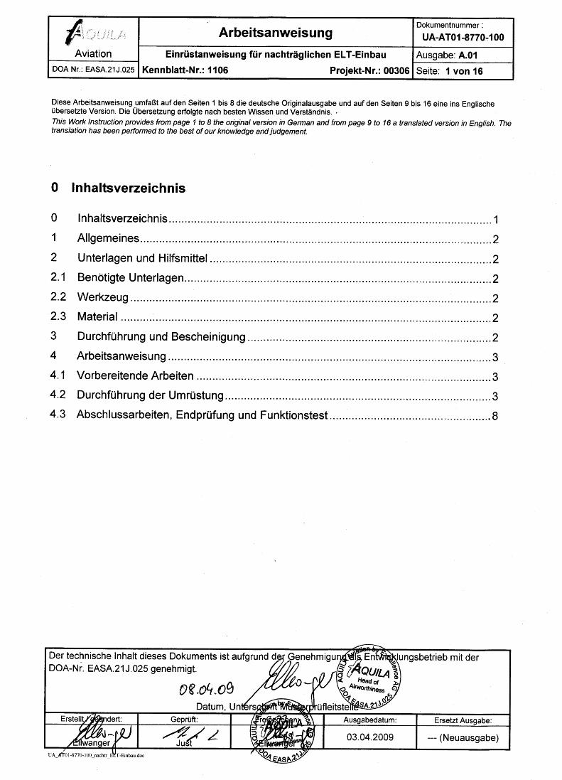
ArbeitsanweisungDokumentnummer :
UA-AT01-8770-100
Aviation Einrüstanweisung für nachträglichen ELT-Einbau Ausgabe: A.01
DOA Nr.: EASA.21J.025 Kennblatt-Nr.: 1106 Projekt-Nr.: 00306 Seite: 2 von 16
UA_AT01-8770-100_A01.doc
1 AllgemeinesDiese Arbeitanweisung beschreibt den Einbauort für ein ELT, dessen Fernbedienung und einerentsprechenden Antenne gemäß der „Liste der freigegebenen Ausrüstung“ (Dok.-Nr: MZ-AT01-0150-001, amMuster AT01 im Zusammenhang mit der Technischen Mitteilung SB-AT01-014.)
2 Unterlagen und Hilfsmittel2.1 Benötigte Unterlagen
Für die Umrüstung/den Einbau der TM-SB-AT01-14 werden die folgenden Unterlagen benötigt:
Pos. Dokumentennummer Unterlagenart und Titel
1 SB-AT01-014 Service Bulletin
2 MZ-AT01-0150-001 Liste der freigegebenen Ausrüstung
2.2 Werkzeug
Die folgenden Werkzeuge werden für die Durchführung der Umrüst-/Einbauarbeiten benötigt:
Pos. Bezeichnung Pos. Bezeichnung
1 Erdungsseil
2 Standard Mechaniker Werkzeugsatz
3 Standard Elektriker Werkzeugsatz
2.3 Material
Entsprechend dem gewählten ELT.
3 Durchführung und BescheinigungDie Arbeiten sind von einem genehmigten Wartungsbetrieb durchzuführen und in Übereinstimmung mitEU-Verordnung 2042/2003 durch einen Prüfer zu bescheinigen.
4 Arbeitsanweisung4.1 Vorbereitende Arbeiten
Herstellung der Leitung für die Fernbedienung (wenn gewünscht).
ArbeitsanweisungDokumentnummer :
UA-AT01-8770-100
Aviation Einrüstanweisung für nachträglichen ELT-Einbau Ausgabe: A.01
DOA Nr.: EASA.21J.025 Kennblatt-Nr.: 1106 Projekt-Nr.: 00306 Seite: 3 von 16
UA_AT01-8770-100_A01.doc
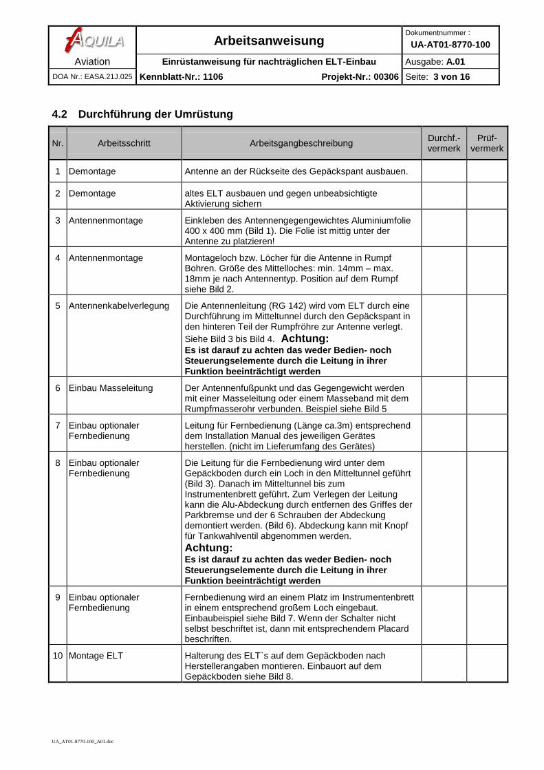
4.2 Durchführung der Umrüstung
Nr. Arbeitsschritt Arbeitsgangbeschreibung Durchf.-vermerk
Prüf-vermerk
1 Demontage Antenne an der Rückseite des Gepäckspant ausbauen.
2 Demontage altes ELT ausbauen und gegen unbeabsichtigteAktivierung sichern
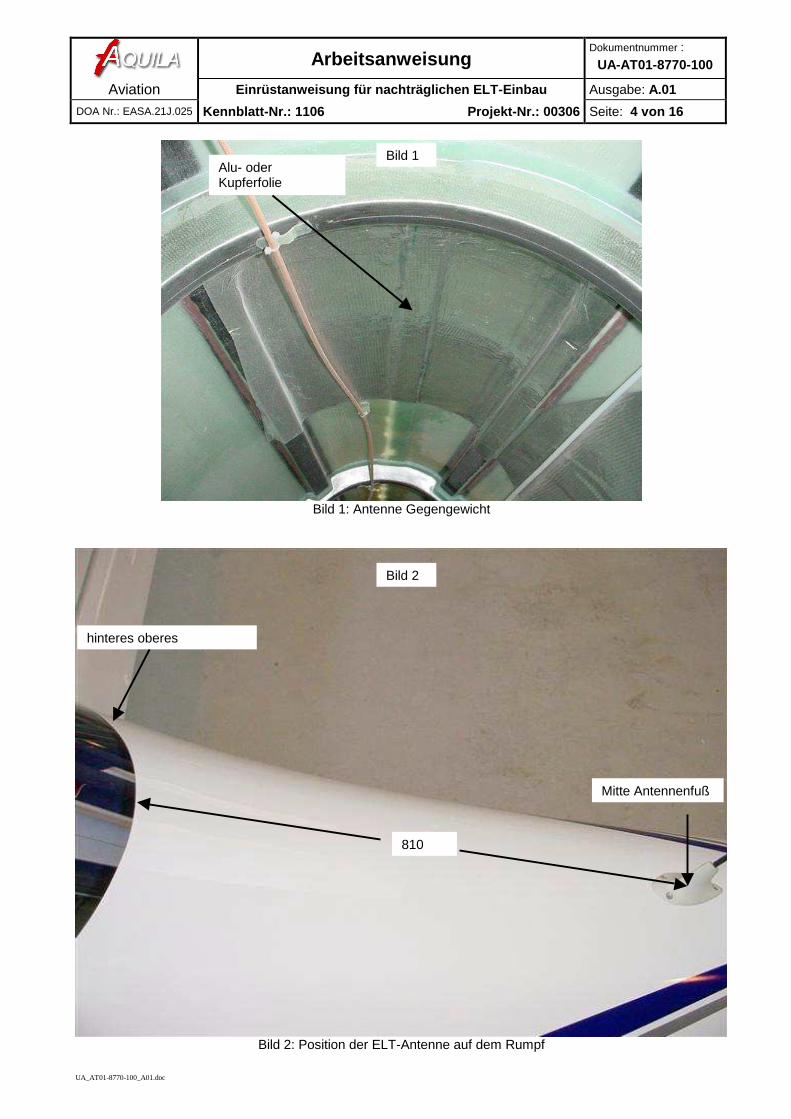
3 Antennenmontage Einkleben des Antennengegengewichtes Aluminiumfolie400 x 400 mm (Bild 1). Die Folie ist mittig unter derAntenne zu platzieren!
4 Antennenmontage Montageloch bzw. Löcher für die Antenne in RumpfBohren. Größe des Mittelloches: min. 14mm – max.18mm je nach Antennentyp. Position auf dem Rumpfsiehe Bild 2.
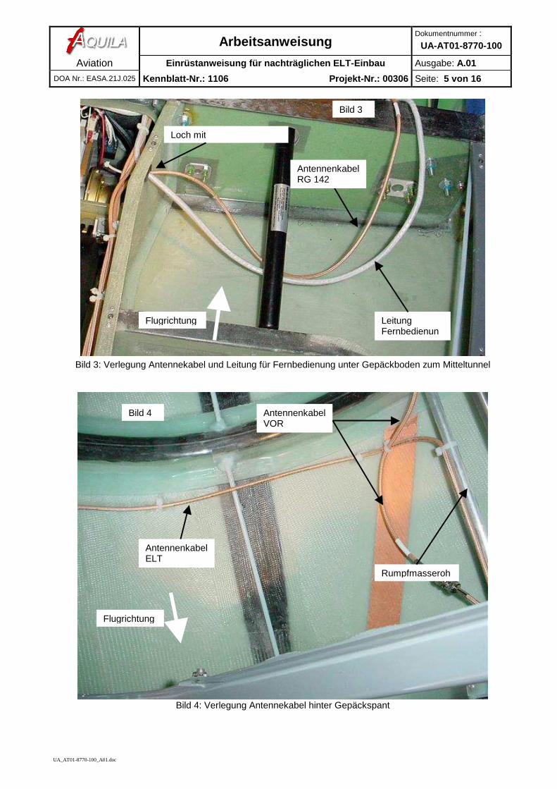
5 Antennenkabelverlegung Die Antennenleitung (RG 142) wird vom ELT durch eineDurchführung im Mitteltunnel durch den Gepäckspant inden hinteren Teil der Rumpfröhre zur Antenne verlegt.Siehe Bild 3 bis Bild 4. Achtung:Es ist darauf zu achten das weder Bedien- nochSteuerungselemente durch die Leitung in ihrerFunktion beeinträchtigt werden
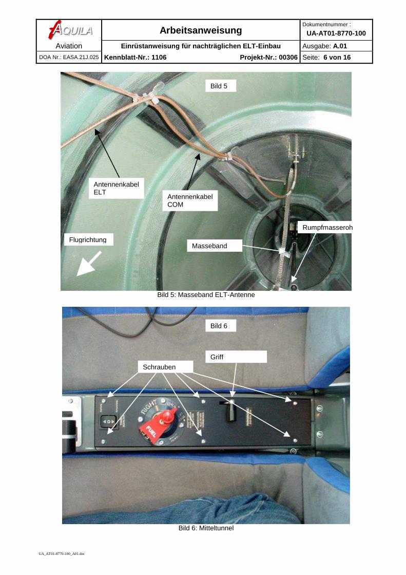
6 Einbau Masseleitung Der Antennenfußpunkt und das Gegengewicht werdenmit einer Masseleitung oder einem Masseband mit demRumpfmasserohr verbunden. Beispiel siehe Bild 5
7 Einbau optionalerFernbedienung
Leitung für Fernbedienung (Länge ca.3m) entsprechenddem Installation Manual des jeweiligen Gerätesherstellen. (nicht im Lieferumfang des Gerätes)
8 Einbau optionalerFernbedienung
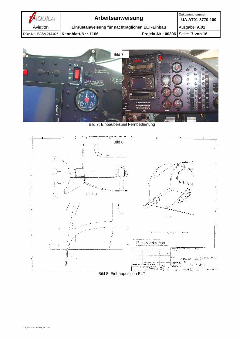
Die Leitung für die Fernbedienung wird unter demGepäckboden durch ein Loch in den Mitteltunnel geführt(Bild 3). Danach im Mitteltunnel bis zumInstrumentenbrett geführt. Zum Verlegen der Leitungkann die Alu-Abdeckung durch entfernen des Griffes derParkbremse und der 6 Schrauben der Abdeckungdemontiert werden. (Bild 6). Abdeckung kann mit Knopffür Tankwahlventil abgenommen werden.Achtung:Es ist darauf zu achten das weder Bedien- nochSteuerungselemente durch die Leitung in ihrerFunktion beeinträchtigt werden
9 Einbau optionalerFernbedienung
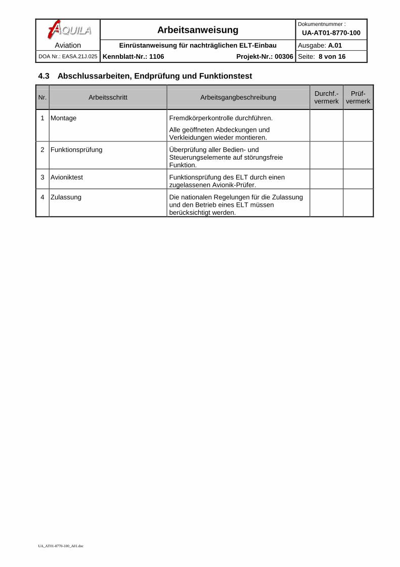
Fernbedienung wird an einem Platz im Instrumentenbrettin einem entsprechend großem Loch eingebaut.Einbaubeispiel siehe Bild 7. Wenn der Schalter nichtselbst beschriftet ist, dann mit entsprechendem Placardbeschriften.
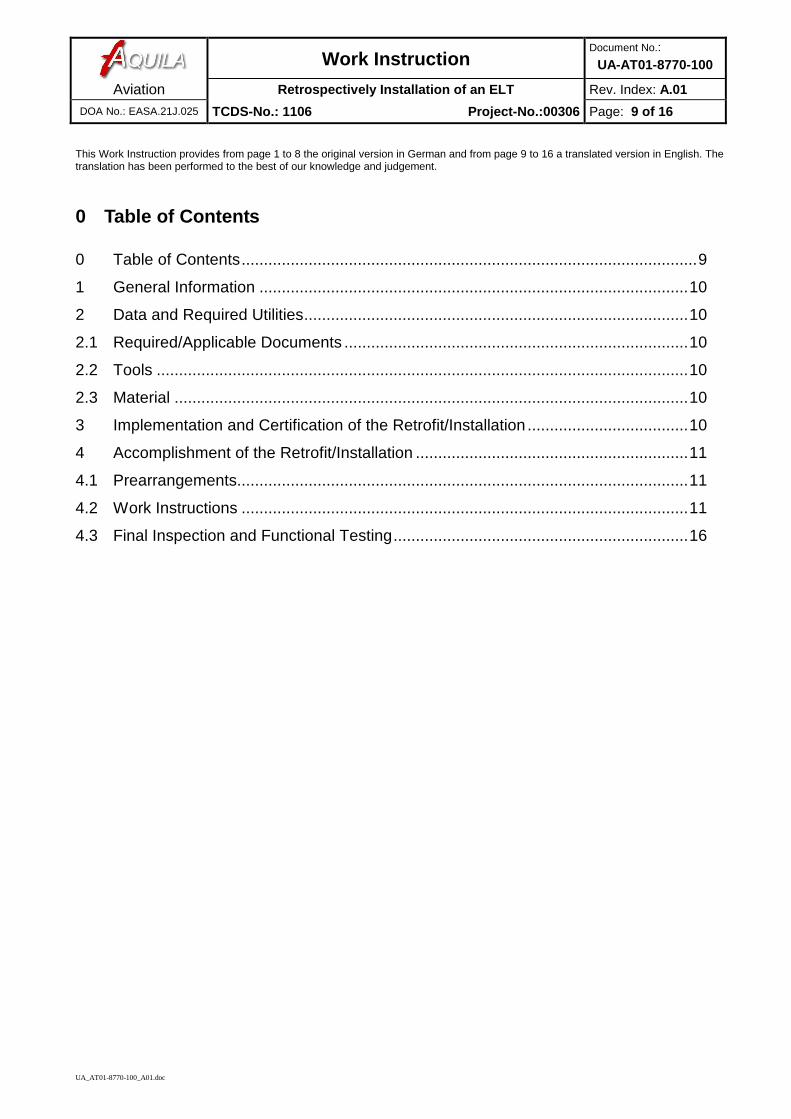
10 Montage ELT Halterung des ELT`s auf dem Gepäckboden nachHerstellerangaben montieren. Einbauort auf demGepäckboden siehe Bild 8.
ArbeitsanweisungDokumentnummer :
UA-AT01-8770-100
Aviation Einrüstanweisung für nachträglichen ELT-Einbau Ausgabe: A.01
DOA Nr.: EASA.21J.025 Kennblatt-Nr.: 1106 Projekt-Nr.: 00306 Seite: 4 von 16
UA_AT01-8770-100_A01.doc
Bild 1: Antenne Gegengewicht
Bild 2: Position der ELT-Antenne auf dem Rumpf
Bild 2
810
Bild 1
Mitte Antennenfuß
Alu- oderKupferfolie
hinteres oberes
ArbeitsanweisungDokumentnummer :
UA-AT01-8770-100
Aviation Einrüstanweisung für nachträglichen ELT-Einbau Ausgabe: A.01
DOA Nr.: EASA.21J.025 Kennblatt-Nr.: 1106 Projekt-Nr.: 00306 Seite: 5 von 16
UA_AT01-8770-100_A01.doc
Bild 3: Verlegung Antennekabel und Leitung für Fernbedienung unter Gepäckboden zum Mitteltunnel
Bild 4: Verlegung Antennekabel hinter Gepäckspant
Loch mit
Bild 4
Bild 3
AntennenkabelELT
LeitungFernbedienung
AntennenkabelVOR
AntennenkabelRG 142
Rumpfmasseroh
Flugrichtung
Flugrichtung
ArbeitsanweisungDokumentnummer :
UA-AT01-8770-100
Aviation Einrüstanweisung für nachträglichen ELT-Einbau Ausgabe: A.01
DOA Nr.: EASA.21J.025 Kennblatt-Nr.: 1106 Projekt-Nr.: 00306 Seite: 6 von 16
UA_AT01-8770-100_A01.doc
Bild 5: Masseband ELT-Antenne
Bild 6: Mitteltunnel
Bild 5
AntennenkabelELT
AntennenkabelCOM
Masseband
Rumpfmasseroh
Griff
Bild 6
Schrauben
Flugrichtung
ArbeitsanweisungDokumentnummer :
UA-AT01-8770-100
Aviation Einrüstanweisung für nachträglichen ELT-Einbau Ausgabe: A.01
DOA Nr.: EASA.21J.025 Kennblatt-Nr.: 1106 Projekt-Nr.: 00306 Seite: 7 von 16
UA_AT01-8770-100_A01.doc
Bild 7: Einbaubeispiel Fernbedienung
Bild 8: Einbauposition ELT
Bild 7
Bild 8
ArbeitsanweisungDokumentnummer :
UA-AT01-8770-100
Aviation Einrüstanweisung für nachträglichen ELT-Einbau Ausgabe: A.01
DOA Nr.: EASA.21J.025 Kennblatt-Nr.: 1106 Projekt-Nr.: 00306 Seite: 8 von 16
UA_AT01-8770-100_A01.doc
4.3 Abschlussarbeiten, Endprüfung und Funktionstest
Nr. Arbeitsschritt Arbeitsgangbeschreibung Durchf.-vermerk
Prüf-vermerk
1 Montage Fremdkörperkontrolle durchführen.
Alle geöffneten Abdeckungen undVerkleidungen wieder montieren.
2 Funktionsprüfung Überprüfung aller Bedien- undSteuerungselemente auf störungsfreieFunktion.
3 Avioniktest Funktionsprüfung des ELT durch einenzugelassenen Avionik-Prüfer.
4 Zulassung Die nationalen Regelungen für die Zulassungund den Betrieb eines ELT müssenberücksichtigt werden.
Work InstructionDocument No.:
UA-AT01-8770-100
Aviation Retrospectively Installation of an ELT Rev. Index: A.01
DOA No.: EASA.21J.025 TCDS-No.: 1106 Project-No.:00306 Page: 9 of 16
UA_AT01-8770-100_A01.doc
This Work Instruction provides from page 1 to 8 the original version in German and from page 9 to 16 a translated version in English. Thetranslation has been performed to the best of our knowledge and judgement.
0 Table of Contents
0 Table of Contents......................................................................................................9
1 General Information ................................................................................................10
2 Data and Required Utilities......................................................................................10
2.1 Required/Applicable Documents .............................................................................10
2.2 Tools .......................................................................................................................10
2.3 Material ...................................................................................................................10
3 Implementation and Certification of the Retrofit/Installation ....................................10
4 Accomplishment of the Retrofit/Installation .............................................................11
4.1 Prearrangements.....................................................................................................11
4.2 Work Instructions ....................................................................................................11
4.3 Final Inspection and Functional Testing..................................................................16
Work InstructionDocument No.:
UA-AT01-8770-100
Aviation Retrospectively Installation of an ELT Rev. Index: A.01
DOA No.: EASA.21J.025 TCDS-No.: 1106 Project-No.:00306 Page: 10 of 16
UA_AT01-8770-100_A01.doc
1 General InformationThis work instruction associated with the Service Bulletin SB-AT01-014 describes the retrospectivelyinstallation of an Emergency Location Transmitter (ELT), the remote control and the antenna in accordancewith the "list of approved equipment" (Doc.-No.: MZ-AT01-0150-001) on the model AQUILA AT01.
2 Data and Required Utilities2.1 Required/Applicable Documents
The following documents are required for the retrofit/ installation:
Pos. Document Number Type of Document and Title
1 SB-AT01-014 Service Bulletin
2 MZ-AT01-0150-001 “List of Approved Equipment” in the latest approved version
2.2 Tools
The following tools are required for the retrofit/ installation:
Pos. Description
1 aircraft ground cable
2 standard mechanic metric tool set
3 standard electrical tool set
2.3 Material
May be vary by type of ELT.
3 Implementation and Certification of the Retrofit/ InstallationThe repair has to be conducted by an approved Maintenance Organisation and has to be certified inaccordance with EU-Regulation 2042/2003.
4 Accomplishment of the Retrofit/Installation4.1 Prearrangements
If a remote control will be installed, a wiring for the remote control (length: ca 3m) must be prepared accordingto the installation manual of the device.
Work InstructionDocument No.:
UA-AT01-8770-100
Aviation Retrospectively Installation of an ELT Rev. Index: A.01
DOA No.: EASA.21J.025 TCDS-No.: 1106 Project-No.:00306 Page: 11 of 16
UA_AT01-8770-100_A01.doc
4.2 Work Instructions
No. Work Step Description SignatureMech.
Sign.Inspect.
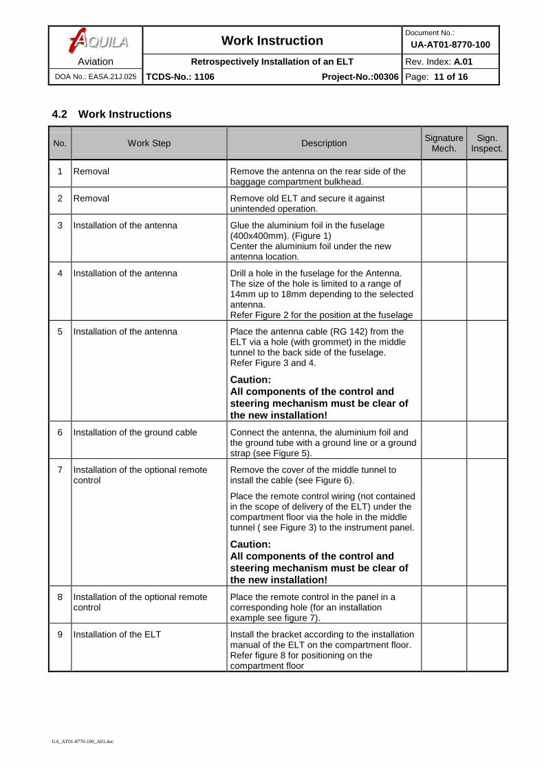
1 Removal Remove the antenna on the rear side of thebaggage compartment bulkhead.
2 Removal Remove old ELT and secure it againstunintended operation.
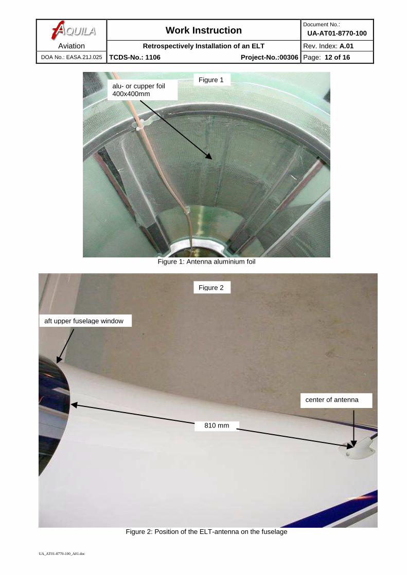
3 Installation of the antenna Glue the aluminium foil in the fuselage(400x400mm). (Figure 1)Center the aluminium foil under the newantenna location.
4 Installation of the antenna Drill a hole in the fuselage for the Antenna.The size of the hole is limited to a range of14mm up to 18mm depending to the selectedantenna.Refer Figure 2 for the position at the fuselage
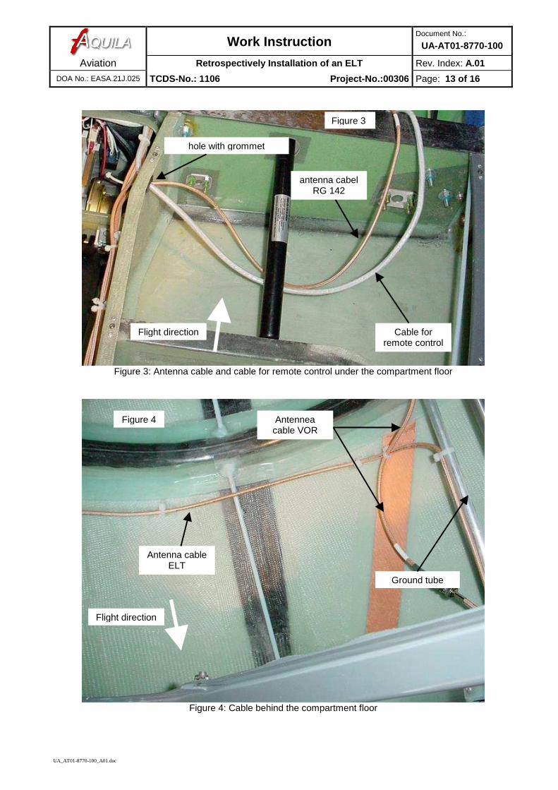
5 Installation of the antenna Place the antenna cable (RG 142) from theELT via a hole (with grommet) in the middletunnel to the back side of the fuselage.Refer Figure 3 and 4.
Caution:All components of the control andsteering mechanism must be clear ofthe new installation!
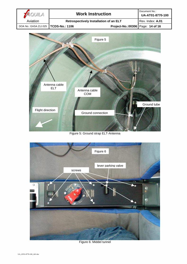
6 Installation of the ground cable Connect the antenna, the aluminium foil andthe ground tube with a ground line or a groundstrap (see Figure 5).
7 Installation of the optional remotecontrol
Remove the cover of the middle tunnel toinstall the cable (see Figure 6).
Place the remote control wiring (not containedin the scope of delivery of the ELT) under thecompartment floor via the hole in the middletunnel ( see Figure 3) to the instrument panel.
Caution:All components of the control andsteering mechanism must be clear ofthe new installation!
8 Installation of the optional remotecontrol
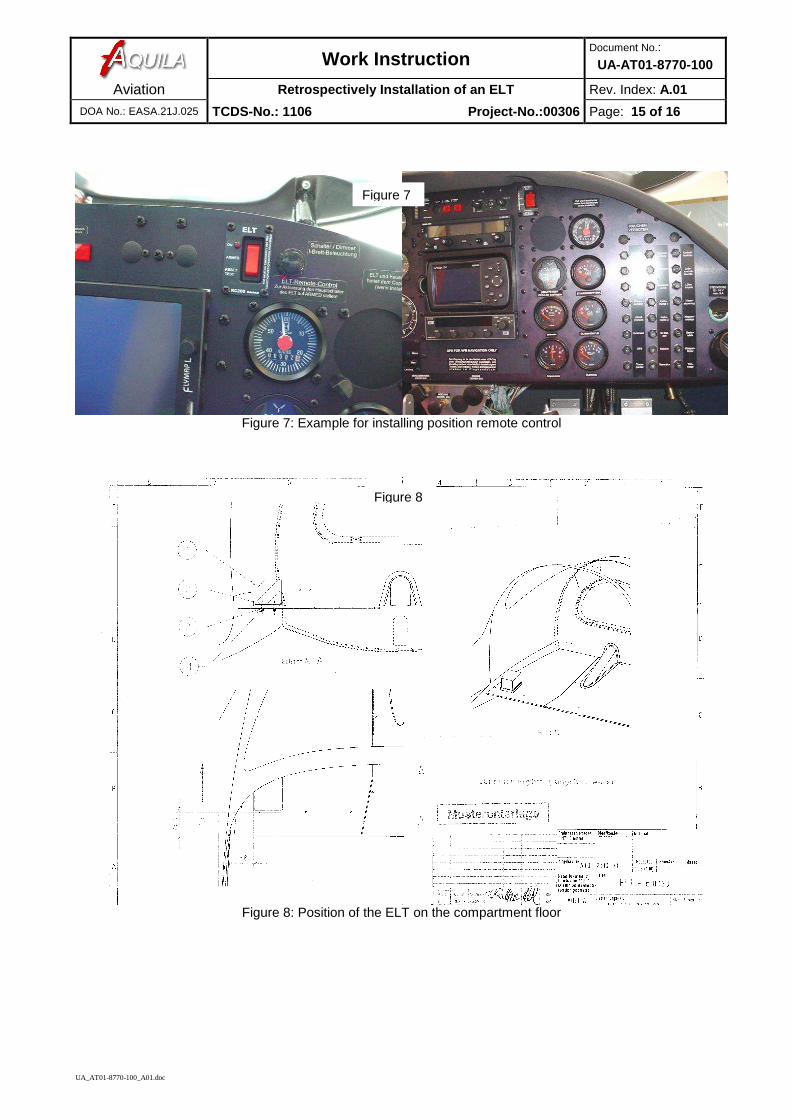
Place the remote control in the panel in acorresponding hole (for an installationexample see figure 7).
9 Installation of the ELT Install the bracket according to the installationmanual of the ELT on the compartment floor.Refer figure 8 for positioning on thecompartment floor
Work InstructionDocument No.:
UA-AT01-8770-100
Aviation Retrospectively Installation of an ELT Rev. Index: A.01
DOA No.: EASA.21J.025 TCDS-No.: 1106 Project-No.:00306 Page: 12 of 16
UA_AT01-8770-100_A01.doc
Figure 1: Antenna aluminium foil
Figure 2: Position of the ELT-antenna on the fuselage
Figure 1alu- or cupper foil400x400mm
Figure 2
810 mm
center of antenna
aft upper fuselage window
Work InstructionDocument No.:
UA-AT01-8770-100
Aviation Retrospectively Installation of an ELT Rev. Index: A.01
DOA No.: EASA.21J.025 TCDS-No.: 1106 Project-No.:00306 Page: 13 of 16
UA_AT01-8770-100_A01.doc
Figure 3: Antenna cable and cable for remote control under the compartment floor
Figure 4: Cable behind the compartment floor
hole with grommet
Figure 4
Figure 3
Antenna cableELT
Cable forremote control
Antenneacable VOR
antenna cabelRG 142
Ground tube
Flight direction
Flight direction
Work InstructionDocument No.:
UA-AT01-8770-100
Aviation Retrospectively Installation of an ELT Rev. Index: A.01
DOA No.: EASA.21J.025 TCDS-No.: 1106 Project-No.:00306 Page: 14 of 16
UA_AT01-8770-100_A01.doc
Figure 5: Ground strap ELT-Antenna
Figure 6: Middel tunnel
Figure 5
Antenna cableELT
Antenna cableCOM
Ground connection
Ground tube
lever parking valve
Figure 6
screws
Flight direction
Work InstructionDocument No.:
UA-AT01-8770-100
Aviation Retrospectively Installation of an ELT Rev. Index: A.01
DOA No.: EASA.21J.025 TCDS-No.: 1106 Project-No.:00306 Page: 15 of 16
UA_AT01-8770-100_A01.doc
Figure 7: Example for installing position remote control
Figure 8: Position of the ELT on the compartment floor
Figure 7
Figure 8
Work InstructionDocument No.:
UA-AT01-8770-100
Aviation Retrospectively Installation of an ELT Rev. Index: A.01
DOA No.: EASA.21J.025 TCDS-No.: 1106 Project-No.:00306 Page: 16 of 16
UA_AT01-8770-100_A01.doc
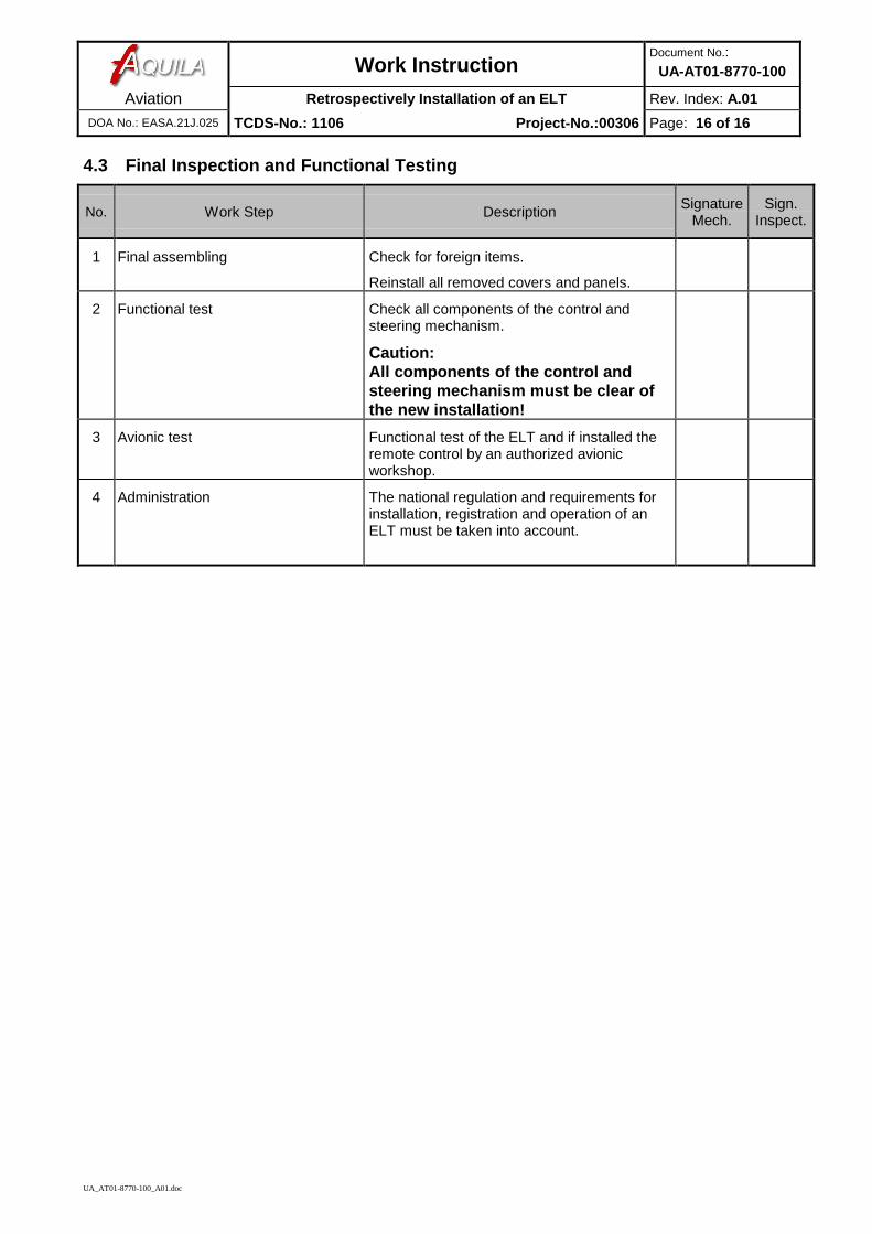
4.3 Final Inspection and Functional Testing
No. Work Step Description SignatureMech.
Sign.Inspect.
1 Final assembling Check for foreign items.
Reinstall all removed covers and panels.
2 Functional test Check all components of the control andsteering mechanism.
Caution:All components of the control andsteering mechanism must be clear ofthe new installation!
3 Avionic test Functional test of the ELT and if installed theremote control by an authorized avionicworkshop.
4 Administration The national regulation and requirements forinstallation, registration and operation of anELT must be taken into account.