Embed Size (px)
Citation preview
Identifier: Revision: Effective Date: Review Date:
SOP-001
2
07/12/2006
03/26/2007
Geology Dept. Document No.: EXACt! - 001
Author: Miguel A. Santiago Rivera
UUnniivveerrssiittyy ooff PPuueerrttoo RRiiccoo MMaayyaaggüüeezz CCaammppuuss
DDeeppaarrttmmeenntt ooff GGeeoollooggyy
UUPPRR--NNSSFF EEaarrtthh XX--rraayy AAnnaallyyssiiss CCeenntteerr ((EEXXAACCtt!!)) Standard Operating Procedure for:
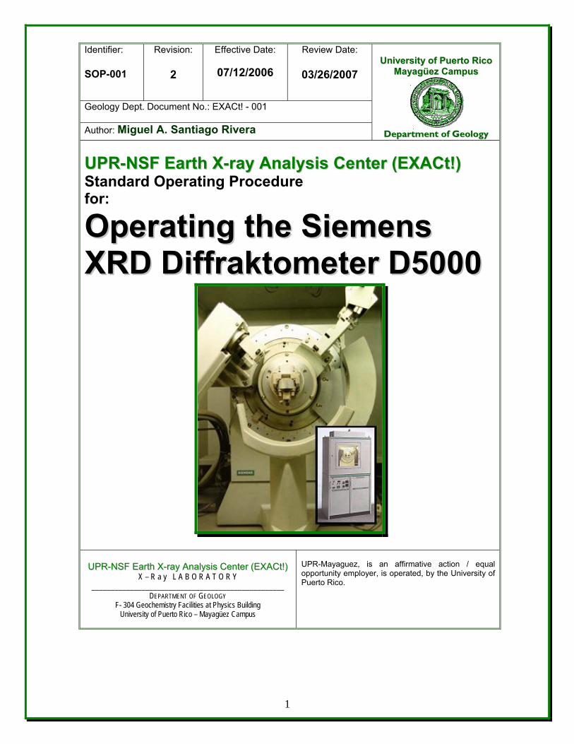
OOppeerraattiinngg tthhee SSiieemmeennss XXRRDD DDiiffffrraakkttoommeetteerr DD55000000
UPR-Mayaguez, is an affirmative action / equal opportunity employer, is operated, by the University of Puerto Rico.
UUPPRR--NNSSFF EEaarrtthh XX--rraayy AAnnaallyyssiiss CCeenntteerr ((EEXXAACCtt!!)) X – R a y L A B O R A T O R Y
__________________________________________________ DEPARTMENT OF GEOLOGY
F- 304 Geochemistry Facilities at Physics Building University of Puerto Rico – Mayagüez Campus
1
Revision Log
Revision No.
Effective Date
Prepared By Description Affected of Changes Pages
R-0 July 12, 2006 Miguel Santiago All New Procedure All
R-1 September 20, 2006
Miguel Santiago Warning in the Procedure
One Page -16
8.6-6
R-2 March 26, 2007 Miguel Santiago X-rays Warning for Pregnant and Cancer patient
One Page -11
8.0 - Procedure \
2
Operating the Siemens Diffraktometer D5000
Table of Contents 1.0 PURPOSE . . . . . . . . 4
2.0 SCOPE . . . . . . . . 4
3.0 TRAINING . . . . . . . . 4
4.0 DEFINITIONS . . . . . . . 4
5.0 RESPONSIBLE PERSONNEL . . . . . 6
6.0 THEORETICAL BACKGROUND . . . . . 6
7.0 EQUIPMENT . . . . . . . . 10
8.0 PROCEDURE . . . . . . . 11
9.0 RECORDS . . . . . . . . 34
10.0 REFERENCES . . . . . . . 34
3
Operating the Siemens Diffraktometer D5000
1.0 PURPOSE This procedure provides instructions for the operation of the Siemens Instruments, incorporated, Model Diffraktometer D5000, x-ray diffraction system. The D5000 model measures atomic spacings in crystals using diffraction of approximately monochromatic x-radiation. It can be used to characterize solid samples ranging in size. This SOP states the responsibilities and describes the methods, procedures and documentation used to obtain X-ray powder diffraction data from Siemens D5000 X-ray Powder Diffractometer at the UPR-NSF Earth X-ray Analysis Center (EXACt), Geochemistry Facilities, Department of Geology, UPR-Mayagüez Campus. 2.0 SCOPE This SOP is a mandatory document and shall be implemented by all Researcher, Faculty member, Technician and/or students participants when using the XRD Diffraktometer D 5000 for the collection of XRD data. This SOP covers elementary physical operation of the instrument and radiation safety compliance requirements. Data interpretation is beyond the scope of this manual.
3.0 TRAINING
3.1 All users of this SOP will be trained by reading the procedure, and the training is documented in accordance with the GLP’s.
3.2 The Geology Task Leader will monitor the proper implementation of
this procedure and ensure that relevant team members have completed all applicable training assignments in accordance with GLP’s.
4.0 DEFINITIONS
4.1 Alignment: The orientation of sample, beam and detector axes. Ideally all three coincide with the eucentric point.
4.2 Circle: Any of the separate mechanisms which rotate the sample or detector under the x-ray beam.
Circle-1 rotates the sample about a vertical axis. Circle-2 turns the detector, also about a vertical axis. Circle-3 tilts the sample about a horizontal axis and
designated chi. Circle-4 rotates the sample about an axis normal to the
sample surface through the center of the holder and called phi (φ).
4
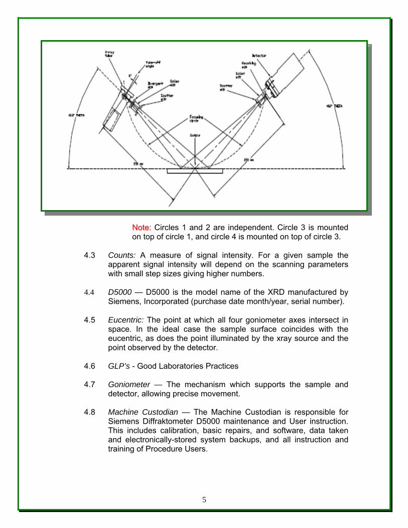
NNoottee:: Circles 1 and 2 are independent. Circle 3 is mounted on top of circle 1, and circle 4 is mounted on top of circle 3.
4.3 Counts: A measure of signal intensity. For a given sample the apparent signal intensity will depend on the scanning parameters with small step sizes giving higher numbers.
4.4 D5000 — D5000 is the model name of the XRD manufactured by Siemens, Incorporated (purchase date month/year, serial number).
4.5 Eucentric: The point at which all four goniometer axes intersect in space. In the ideal case the sample surface coincides with the eucentric, as does the point illuminated by the xray source and the point observed by the detector.
4.6 GLP’s - Good Laboratories Practices 4.7 Goniometer — The mechanism which supports the sample and
detector, allowing precise movement. 4.8 Machine Custodian — The Machine Custodian is responsible for
Siemens Diffraktometer D5000 maintenance and User instruction. This includes calibration, basic repairs, and software, data taken and electronically-stored system backups, and all instruction and training of Procedure Users.
5
4.9 Monochrometer: A device, which selects x-rays of a specific energy, traveling along a specific axis. Two channel cut germanium crystals are mounted as periscopes in opposition. The radiation diffracts from the first surface to the second, where it diffracts again with direction unchanged but position displaced by the projected width of the channel. The second crystal reverses the displacement, so the beam direction and position are identical to the original beam. The crystal lattice spacing in the monochrometer is effectively the "metric standard" to which the sample is compared.
4.10 Powder Diffraction - X-ray powder diffraction finds frequent use in materials science because sample preparation is relatively easy, and the test itself is often rapid and non-destructive. The vast majorities of engineering materials is crystalline, and even those that are not yielding some useful information in diffraction experiments. The pattern of powder diffraction peaks can be used to quickly identify materials and changes in peak width or position can be used to determine crystal size, purity, and texture.
4.11 Reflection: Sometimes used as a synonym for diffraction. There is a big difference, however: in optical reflection, the _direction_ of the reflected beam depends on reflector orientation. In diffraction, the intensity of the diffracted beam depends on orientation but the direction is fixed in the coordinate system of the incident beam.
4.11 SOP - Standard Operational Procedure
4.12 X-ray - Electromagnetic radiation of very short wavelength (0.01 to 100 nm) produced when an electron hits a piece of metal in an evacuated tube.
4.13 XRD: X ray diffraction - The atomic planes of a crystal cause an incident beam of X-rays (if wavelength is approximately the magnitude of the interatomic distance) to interfere with one another as they leave the crystal.
4.14 XRD, Siemens Diffraktometer D5000 system — The system includes a chiller to control the temperature, Driffac Plus software and PC to collect the data.
6
5.0 RESPONSIBLE PERSONNEL The following personnel are responsible for activities identified in this procedure. 5.1 Scientific Instrumentation Specialist 5.2 Faculty Member 5.3 Researcher 5.4 Student Participant
6.0 THEORETICAL BACKGROUND
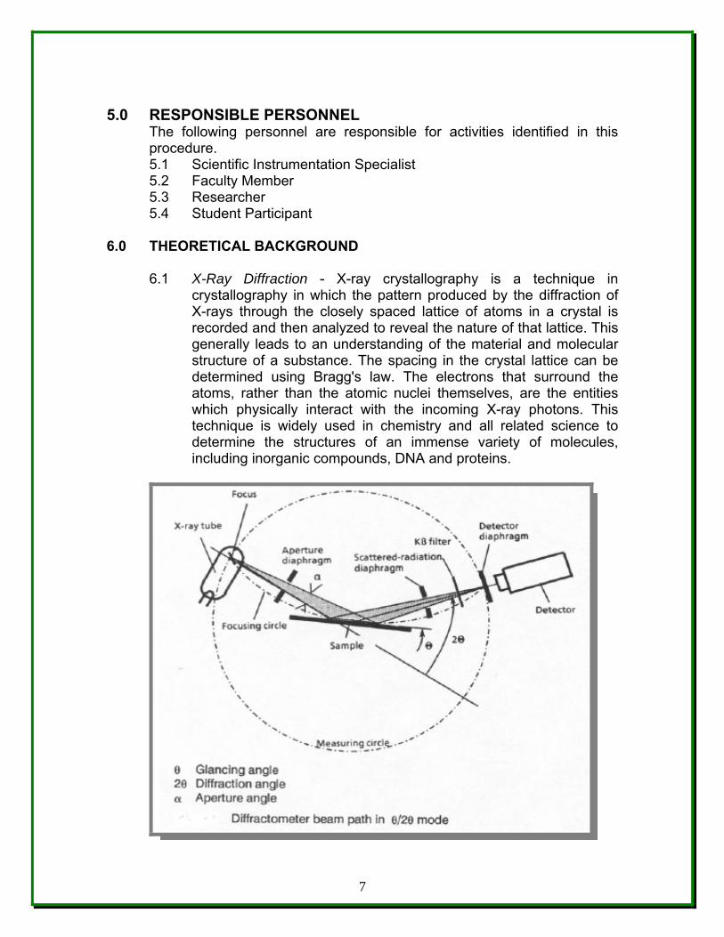
6.1 X-Ray Diffraction - X-ray crystallography is a technique in crystallography in which the pattern produced by the diffraction of X-rays through the closely spaced lattice of atoms in a crystal is recorded and then analyzed to reveal the nature of that lattice. This generally leads to an understanding of the material and molecular structure of a substance. The spacing in the crystal lattice can be determined using Bragg's law. The electrons that surround the atoms, rather than the atomic nuclei themselves, are the entities which physically interact with the incoming X-ray photons. This technique is widely used in chemistry and all related science to determine the structures of an immense variety of molecules, including inorganic compounds, DNA and proteins.
7
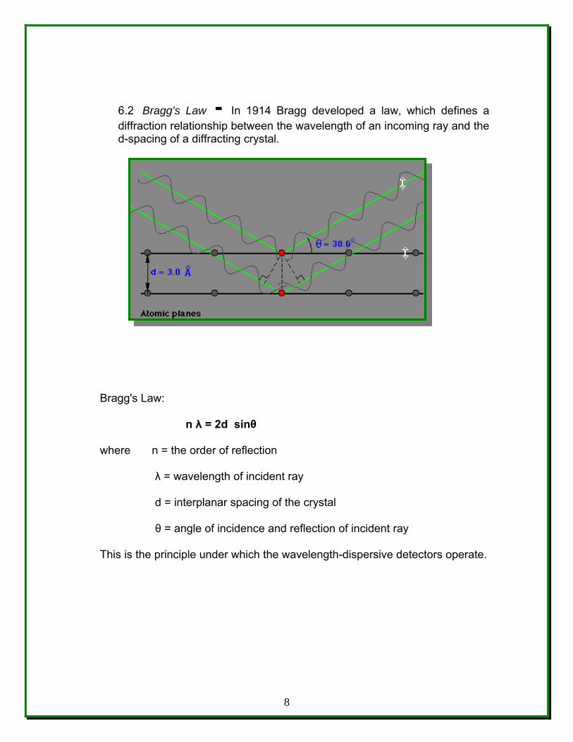
6.2 Bragg's Law - In 1914 Bragg developed a law, which defines a diffraction relationship between the wavelength of an incoming ray and the d-spacing of a diffracting crystal.
Bragg's Law:
n λ = 2d sinθ
where n = the order of reflection
λ = wavelength of incident ray
d = interplanar spacing of the crystal
θ = angle of incidence and reflection of incident ray
This is the principle under which the wavelength-dispersive detectors operate.
8
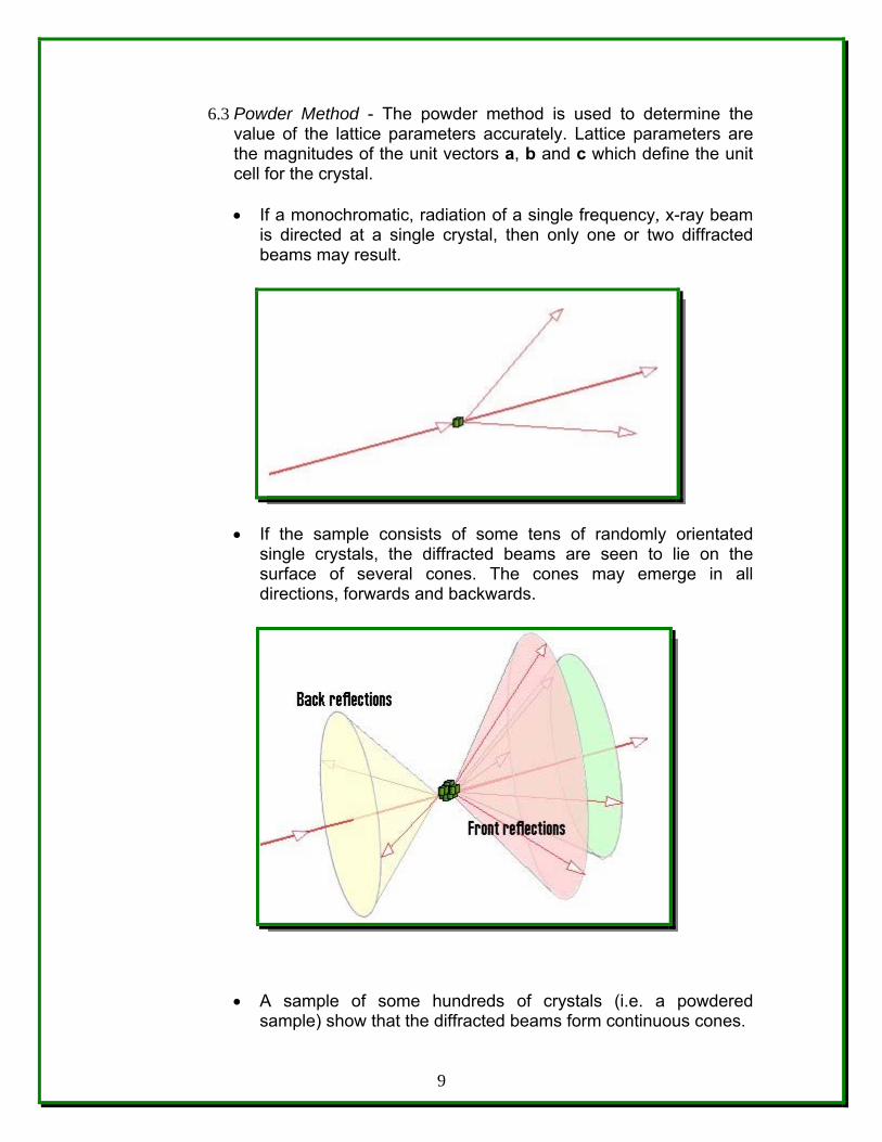
6.3 Powder Method - The powder method is used to determine the value of the lattice parameters accurately. Lattice parameters are the magnitudes of the unit vectors a b c, and which define the unit cell for the crystal.
• If a monochromatic, radiation of a single frequency, x-ray beam is directed at a single crystal, then only one or two diffracted beams may result.
• If the sample consists of some tens of randomly orientated single crystals, the diffracted beams are seen to lie on the surface of several cones. The cones may emerge in all directions, forwards and backwards.
• A sample of some hundreds of crystals (i.e. a powdered sample) show that the diffracted beams form continuous cones.
9
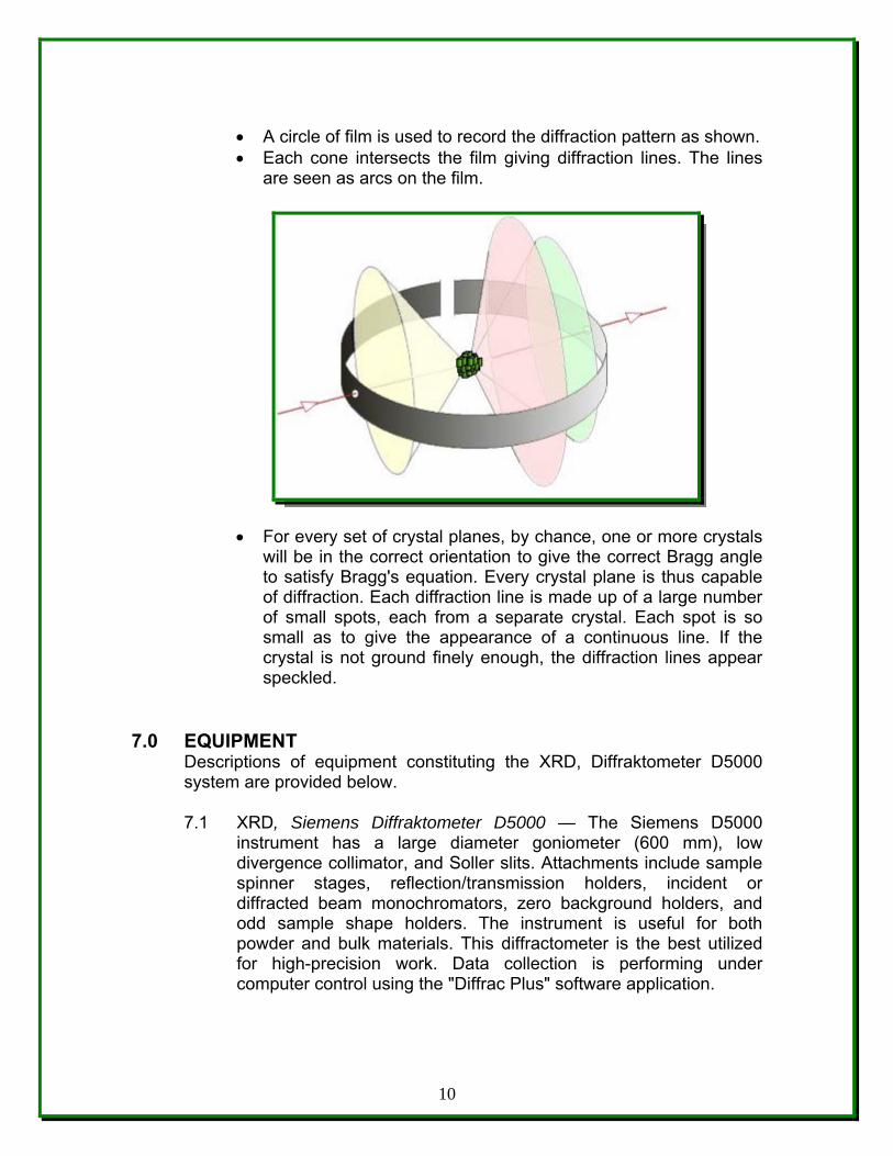
• A circle of film is used to record the diffraction pattern as shown. • Each cone intersects the film giving diffraction lines. The lines
are seen as arcs on the film.
• For every set of crystal planes, by chance, one or more crystals will be in the correct orientation to give the correct Bragg angle to satisfy Bragg's equation. Every crystal plane is thus capable of diffraction. Each diffraction line is made up of a large number of small spots, each from a separate crystal. Each spot is so small as to give the appearance of a continuous line. If the crystal is not ground finely enough, the diffraction lines appear speckled.
7.0 EQUIPMENT
Descriptions of equipment constituting the XRD, Diffraktometer D5000 system are provided below.
7.1 XRD, Siemens Diffraktometer D5000 — The Siemens D5000 instrument has a large diameter goniometer (600 mm), low divergence collimator, and Soller slits. Attachments include sample spinner stages, reflection/transmission holders, incident or diffracted beam monochromators, zero background holders, and odd sample shape holders. The instrument is useful for both powder and bulk materials. This diffractometer is the best utilized for high-precision work. Data collection is performing under computer control using the "Diffrac Plus" software application.
10
8.0 PROCEDURE NNoottee:: All personnel performing work, under the UUPPRR--NNSSFF EEaarrtthh XX--rraayy AAnnaallyyssiiss CCeenntteerr ((EEXXAACCtt)) quality program may follow this standard operating procedure (SOP) for XRD analysis. May use their own procedure(s) as long as the substitute, only if, meets the minimum requirements prescribed by the UUPPRR--NNSSFF EEaarrtthh XX--rraayy AAnnaallyyssiiss CCeenntteerr ((EEXXAACCtt)) Plan or are better in the performing, and have been approved by the Director of the Department of Geology, UPR-Mayagüez Campus, before the commencement of the activitie(s). NNoottee:: UUPPRR--NNSSFF EEaarrtthh XX--rraayy AAnnaallyyssiiss CCeenntteerr ((EEXXAACCtt!!)) personnel may produce paper copies of this procedure printed from the controlled-document electronic file. However, it is their responsibility to ensure that they are trained to and utilizing the current version of this procedure. The author may be contacted if text is unclear. Deviations from SOPs are made in accordance with Department Director approval and documented in accordance with the GLP’s. WWAARRNNIINNGG: X-rays equipments may produce radiation out of the equipment. Pregnant may risk in injury to the unborn child and/or may interfere with the treatment for cancer patient. If you are pregnant or cancer patient, consult your physician before to use and/or be exposed to x-rays equipments.
8.1 Introduction — The XRD, Siemens Diffraktometer D5000 (Purchase Date: month/year, Siemens Service Serial Number: 001333 and UPRM-Property Number: 059933) allows the determination of crystalline structures and the identification of inorganic crystalline solids based on these properties for mineral composition of the samples. The construction of the analytical chamber allows samples of various sizes to be analyzed. The D-5000 is completely computer-controlled for data acquisition. Phase identification may also, be automated by search/match software and a CD-ROM archive of the JCPD tables.
8.2 Sample Preparation - samples to be examined with the XRD machine,
must be in a form or size that can be inserted into or attached to and XRD – D 5000 stage mount and very well compacted. Quantitative microanalysis routines assume that all samples for analysis will be relatively flat and that analysis sites will be normal to the beam incidence.
Sample requirements for powder XRD vary with the nature of the material. A typical sample holder is a 2-mm thick plate with a 20-mm square hole in the center. For materials that diffract strongly (many inorganic materials), Scotch double tape is placed over the hole with the sticky side up. About 10-20 mg of the material of interest is then spread on the tape and smoothed flat. The tape is primarily amorphous and so does not generally interfere with the pattern being collected.
11
For materials that diffract less strongly such as organic molecular crystals, more sample (100-200 mg) must be used. One way of doing this is to tape or glue a microscope slide to the back side of the sample holder. The depression in the holder is then filled with sample and smoothed flat.
NNoottee:: XRD samples should be well-ground in a mortar and/or pestles. This creates a uniform particle size and ensures that all possible crystallite orientations are present in the sample. A special problem that can arise in sample preparation is called preferred orientation which usually occurs with rod or plate-like crystals. For example, plate-like crystals tend to lie flat on the sample holder; very few will have a perpendicular orientation. As there is no longer a random orientation of crystallites some of the x-ray reflections that would be expected are unusually weak or missing altogether.
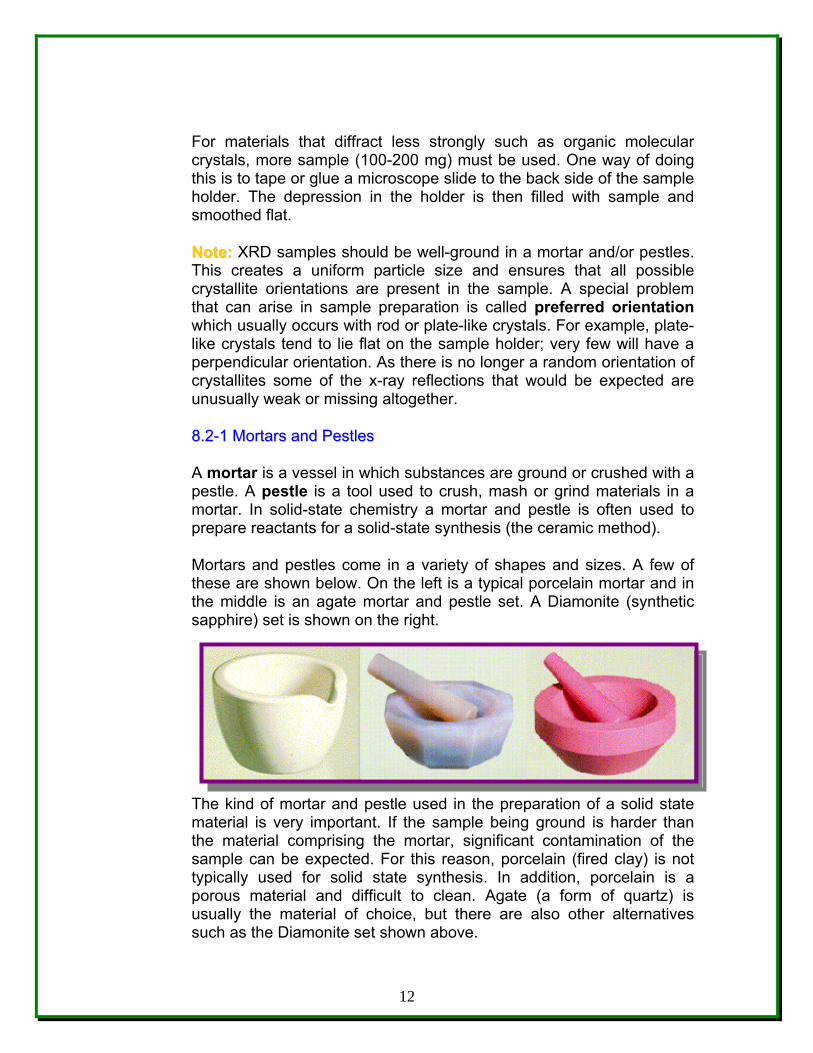
88..22--11 MMoorrttaarrss aanndd PPeessttlleess
A mortar is a vessel in which substances are ground or crushed with a pestle. A pestle is a tool used to crush, mash or grind materials in a mortar. In solid-state chemistry a mortar and pestle is often used to prepare reactants for a solid-state synthesis (the ceramic method).
Mortars and pestles come in a variety of shapes and sizes. A few of these are shown below. On the left is a typical porcelain mortar and in the middle is an agate mortar and pestle set. A Diamonite (synthetic sapphire) set is shown on the right.
The kind of mortar and pestle used in the preparation of a solid state material is very important. If the sample being ground is harder than the material comprising the mortar, significant contamination of the sample can be expected. For this reason, porcelain (fired clay) is not typically used for solid state synthesis. In addition, porcelain is a porous material and difficult to clean. Agate (a form of quartz) is usually the material of choice, but there are also other alternatives such as the Diamonite set shown above.
12
In a typical solid state synthesis, the reactants are placed in a mortar and ground by hand with the pestle. Acetone or an alcohol is sometimes added to ease grinding. Grinding is continued until the mixture is homogeneous, the particles are no longer getting smaller, and the solvent has evaporated. With good technique, powders with an average diameter of 10 microns (10-3 cm) can be prepared.
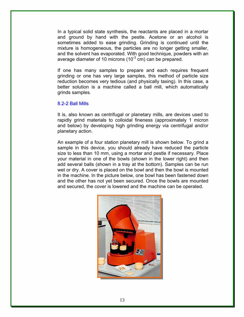
If one has many samples to prepare and each requires frequent grinding or one has very large samples, this method of particle size reduction becomes very tedious (and physically taxing). In this case, a better solution is a machine called a ball mill, which automatically grinds samples. 88..22--22 BBaallll MMiillllss It is, also known as centrifugal or planetary mills, are devices used to rapidly grind materials to colloidal fineness (approximately 1 micron and below) by developing high grinding energy via centrifugal and/or planetary action.
An example of a four station planetary mill is shown below. To grind a sample in this device, you should already have reduced the particle size to less than 10 mm, using a mortar and pestle if necessary. Place your material in one of the bowls (shown in the lower right) and then add several balls (shown in a tray at the bottom). Samples can be run wet or dry. A cover is placed on the bowl and then the bowl is mounted in the machine. In the picture below, one bowl has been fastened down and the other has not yet been secured. Once the bowls are mounted and secured, the cover is lowered and the machine can be operated.
13
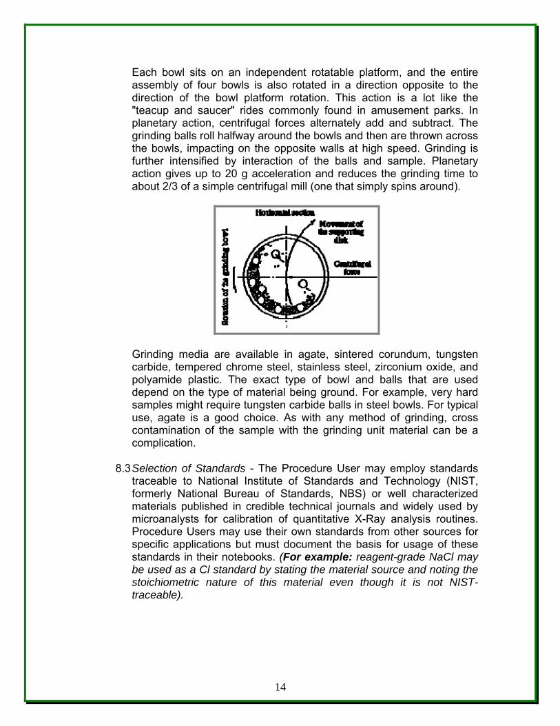
Each bowl sits on an independent rotatable platform, and the entire assembly of four bowls is also rotated in a direction opposite to the direction of the bowl platform rotation. This action is a lot like the "teacup and saucer" rides commonly found in amusement parks. In planetary action, centrifugal forces alternately add and subtract. The grinding balls roll halfway around the bowls and then are thrown across the bowls, impacting on the opposite walls at high speed. Grinding is further intensified by interaction of the balls and sample. Planetary action gives up to 20 g acceleration and reduces the grinding time to about 2/3 of a simple centrifugal mill (one that simply spins around).
Grinding media are available in agate, sintered corundum, tungsten carbide, tempered chrome steel, stainless steel, zirconium oxide, and polyamide plastic. The exact type of bowl and balls that are used depend on the type of material being ground. For example, very hard samples might require tungsten carbide balls in steel bowls. For typical use, agate is a good choice. As with any method of grinding, cross contamination of the sample with the grinding unit material can be a complication.
8.3 Selection of Standards - The Procedure User may employ standards traceable to National Institute of Standards and Technology (NIST, formerly National Bureau of Standards, NBS) or well characterized materials published in credible technical journals and widely used by microanalysts for calibration of quantitative X-Ray analysis routines. Procedure Users may use their own standards from other sources for specific applications but must document the basis for usage of these standards in their notebooks. (For example: reagent-grade NaCl may be used as a Cl standard by stating the material source and noting the stoichiometric nature of this material even though it is not NIST-traceable).
14
8.4 Sample Insertion and XRD-D5000 Operation - Detailed operating instructions for the XRD-D5000 system are given in the XRD-D5000 and DIFFRACplus Manuals stored in the laboratory -NSF Earth X-ray Analysis Center (EXACt) in the vertical file. After training, the Procedure User should refer to the manuals when questions arise or consult with the Machine Custodian to solve specific problems.
8.5 Sample Control – Sample identification will be based on the unique
identifier labeled on the sample. This will typically be an etched identification on the plate holder for analysis.
8.6 Performing the Standard Operation Procedure for XRD Siemens
Diffraktometer D5000 – Qualitative Scanning.
8.6.1 Environmental Considerations – Maintain the room temperature between 17ºC (62ºF) and 26ºC (78ºF), at a gradient less than 0.5ºC/hr and a fluctuation of no greater than 2ºC. Relative humidity should not exceed 80% and should be no less than 20%. Ensure that the heat produced from the generator, spectrometer, computer and vacuum pump is adequately dissipated by ventilation or air conditioning and located so that the air flow is not directed at the instrument. A clean, dust-free environment is also necessary. Avoid the direct sunlight to XRD machine.
8.6.2 Chiller - must be turn on 5 to 10 minutes before of the
operating the XRD machine at pressure of 60 – 80 psi and a temperature of 65 F.
8.6.3 On the panel, of the left side in front of the XRD machine;
• Turn on the ggrreeeenn switch of ON and OFF. • Turn the key. • Press the yyeellllooww button.
8.6.4 Now on the panel of the right side of the XRD machine, pull
out the drawer and then; • Press, “Shift” button. • Press, “X-ray” button. • Press, “#1” button. • Press, “Enter” button.
8.6.5 Back on the left side of the panel, in front of the XRD
machine; • Press the ggrreeeenn button, then an “X-ray indicator” will turn on.
15
8.6.6 Aspects of X-ray tube design and operation - A new tube is about $3,000 and should last several thousand hours. 8.6.6.1 Increase the current (mA) and the voltage (kV), 10
units by 10 units, waiting 1 minute between each rising to get the optimum values of 40-mA to 50-mA for the current and 45-kV to 55-kV and for the voltage to increase the intensity of the peaks.
8.6.6.2 An important rule of thumb: • When turning a tube up, increase the kV first, and
then increase the mA. • When turning a tube down, decrease the mA first,
and then decrease the kV
8.6.7 Now, open the XRD clear door to access the goniometer. 8.6.8 Remove the knob to access the goniometer, and place the
sample(s) in order from 1 to 40 positions.
8.6.9 Choose between 1-mm and 2-mm slit. NNoottee:: Usually for geological samples use 2-mm and for thin films 1-mm.
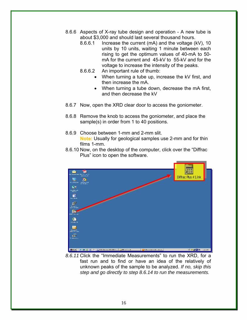
8.6.10 Now, on the desktop of the computer, click over the “Diffrac Plus” icon to open the software.
8.6.11 Click the “Immediate Measurements” to run the XRD, for a fast run and to find or have an idea of the relatively of unknown peaks of the sample to be analyzed. If no, skip this step and go directly to step 8.6.14 to run the measurements.
16
Diffrac Plus #1.lnk
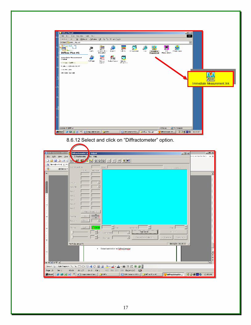
8.6.12 Select and click on “Diffractometer” option.
17
Immediate Measurement.lnk
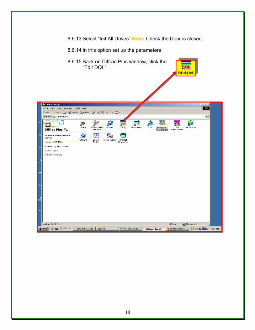
8.6.13 Select “Init All Drives” NNoottee:: Check the Door is closed.
8.6.14 In this option set up the parameters
8.6.15 Back on Diffrac Plus window, click the
“Edit DQL”.
18
Editdql.lnk
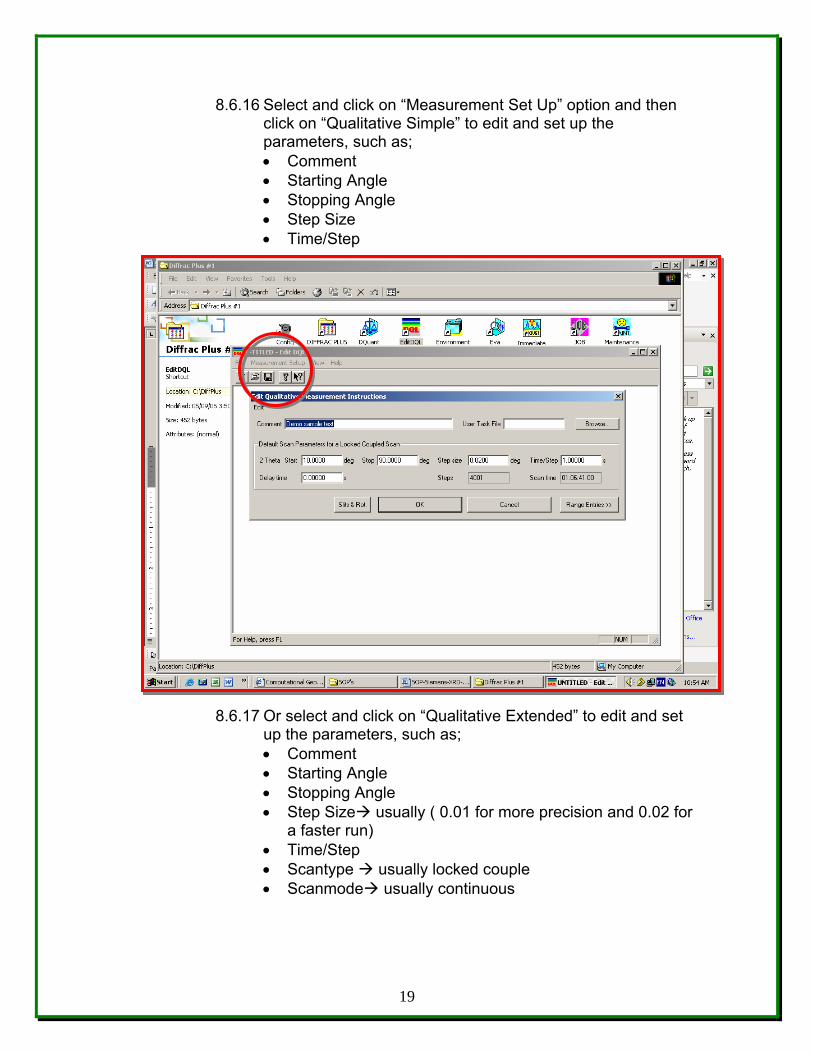
8.6.16 Select and click on “Measurement Set Up” option and then click on “Qualitative Simple” to edit and set up the parameters, such as; • Comment • Starting Angle • Stopping Angle • Step Size • Time/Step
8.6.17 Or select and click on “Qualitative Extended” to edit and set up the parameters, such as; • Comment • Starting Angle • Stopping Angle • Step Size usually ( 0.01 for more precision and 0.02 for
a faster run) • Time/Step • Scantype usually locked couple • Scanmode usually continuous
19
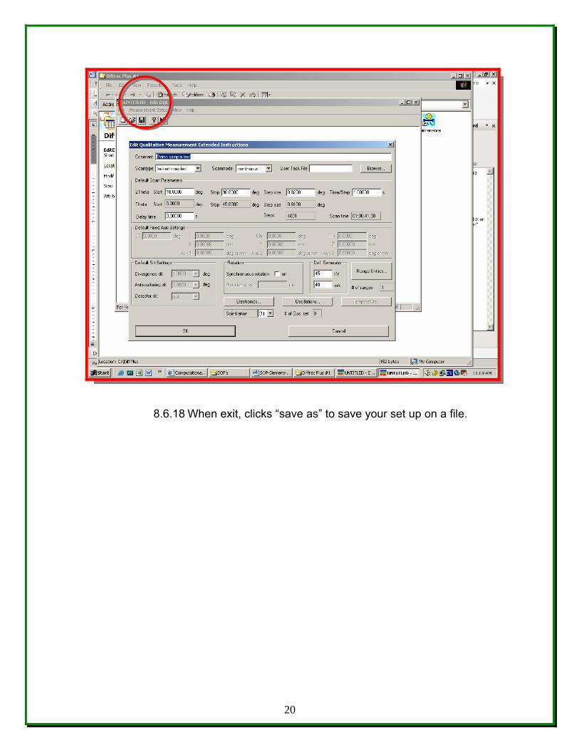
8.6.18 When exit, clicks “save as” to save your set up on a file.
20
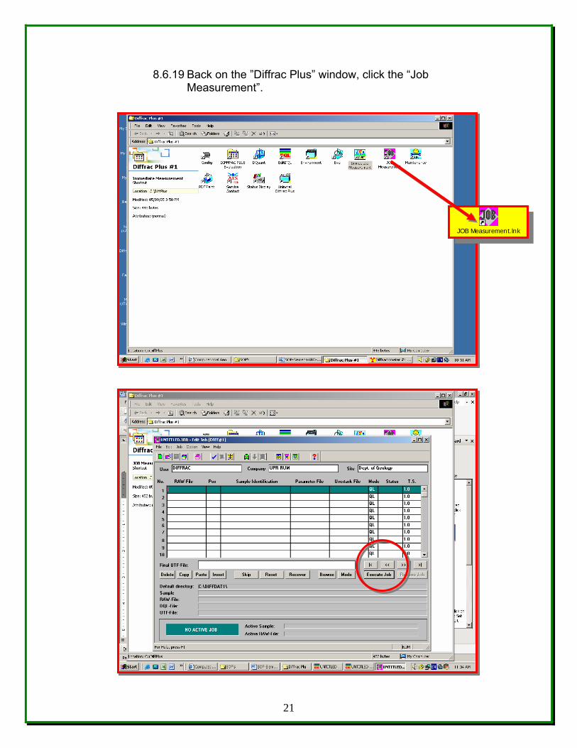
8.6.19 Back on the ”Diffrac Plus” window, click the “Job Measurement”.
21
JOB Measurement.lnk
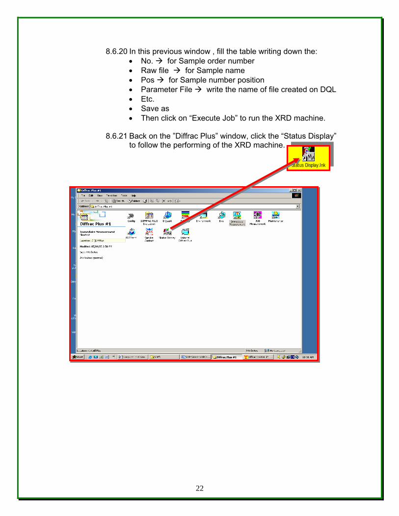
8.6.20 In this previous window , fill the table writing down the: • No. for Sample order number • Raw file for Sample name • Pos for Sample number position • Parameter File write the name of file created on DQL • Etc. • Save as • Then click on “Execute Job” to run the XRD machine.
8.6.21 Back on the ”Diffrac Plus” window, click the “Status Display”
to follow the performing of the XRD machine.
22
Status Display.lnk
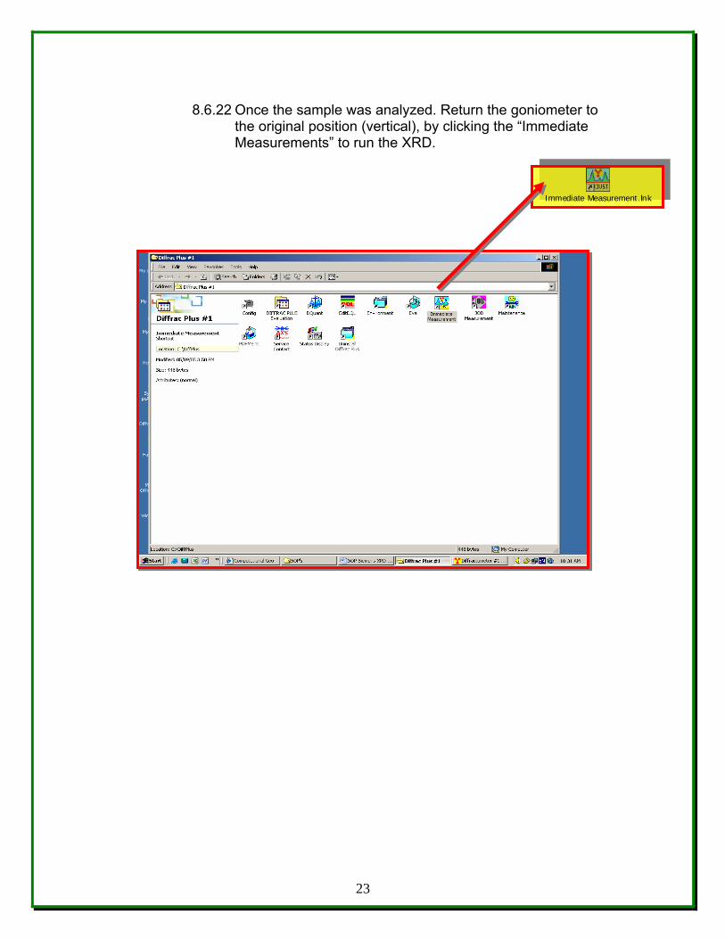
8.6.22 Once the sample was analyzed. Return the goniometer to
the original position (vertical), by clicking the “Immediate Measurements” to run the XRD.
23
Immediate Measurement.lnk
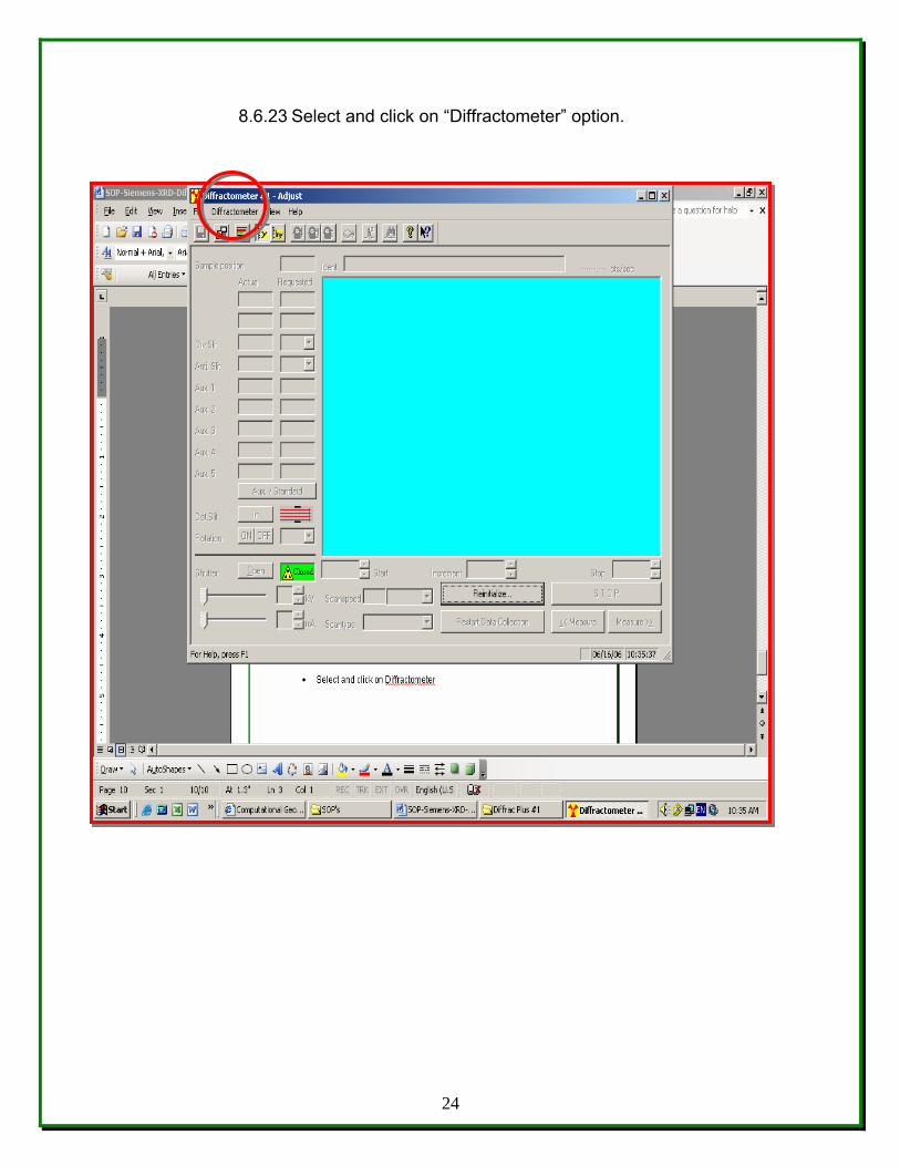
8.6.23 Select and click on “Diffractometer” option.
24
8.6.24 Select “Init All Drives”. The goniometer will reach the vertical
position.
8.6.25 Back on the left side of the panel, in front of the XRD machine; • Decrease the current (mA) and the voltage (kV), 10 units
by 10 units, waiting 1 minute between each time to get the minimum values of 5-mA and 20-kV.
• Press the yyeellllooww button, • Press the rreedd button, • Then an “X-ray indicator” will turn off. • Turn the key. • Turn on the ggrreeeenn switch of ON and OFF.
8.6.26 The Chiller – must turn off 30 minutes after operating the
XRD machine (at pressure of 60 – 80 psi and a temperature of 65 F.)
8.7 Data Acquisition and Reduction - Data may consist of image
information and/or elemental information. Image and elemental information may be processed following instructions in the XRD D5000 and “Diffrac Plus” Software Manuals. Image and elemental information may be photographed and/or printed on paper following instructions in the reference Manual if an electronic copy or a hard copy is desired. The software package “Diffrac Plus” comprises software used for acquisition and reduction of quantitative elemental data.
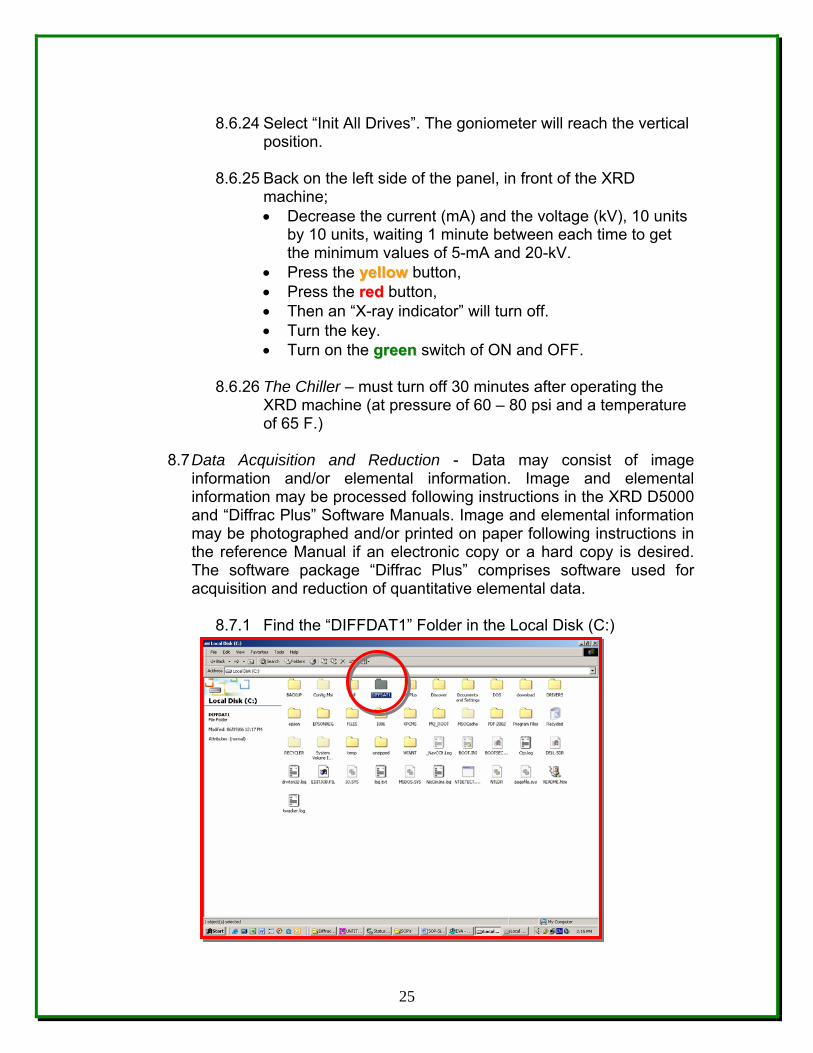
8.7.1 Find the “DIFFDAT1” Folder in the Local Disk (C:)
25
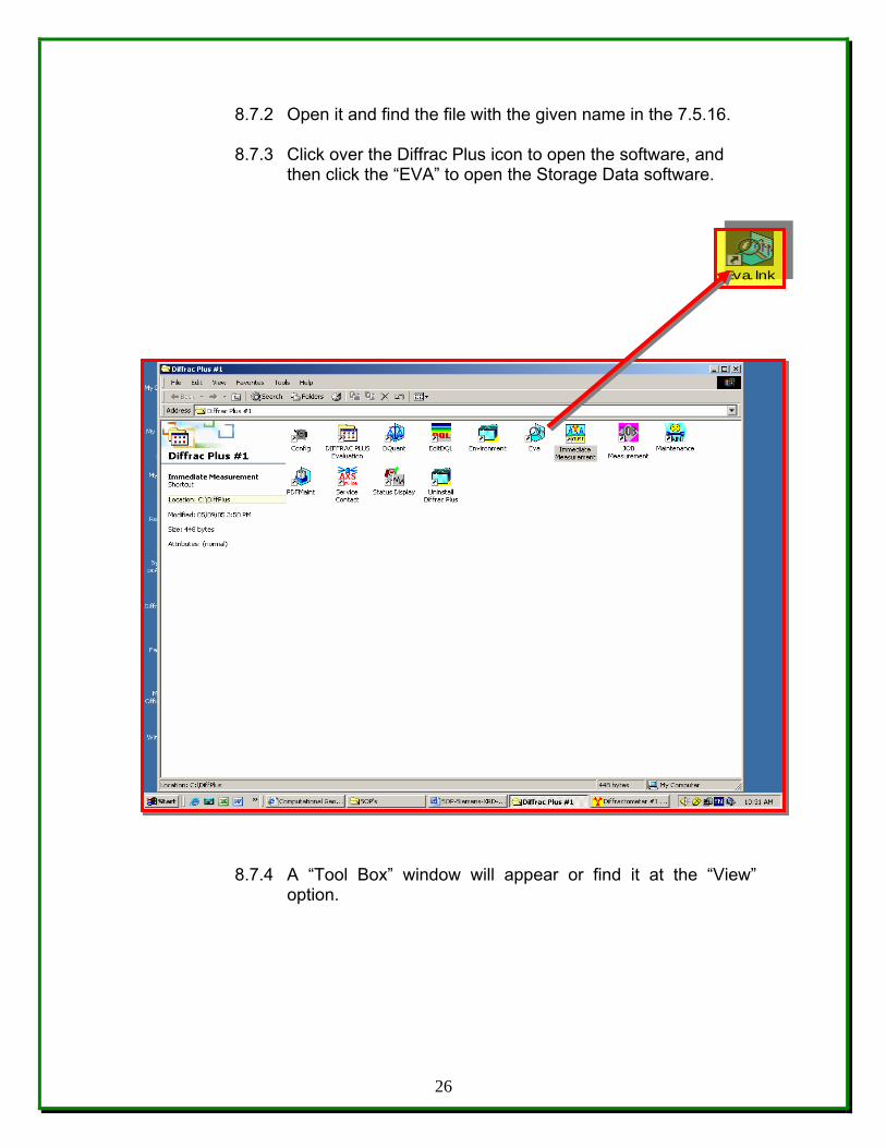
8.7.2 Open it and find the file with the given name in the 7.5.16. 8.7.3 Click over the Diffrac Plus icon to open the software, and
then click the “EVA” to open the Storage Data software.
8.7.4 A “Tool Box” window will appear or find it at the “View” option.
26
Eva.lnk
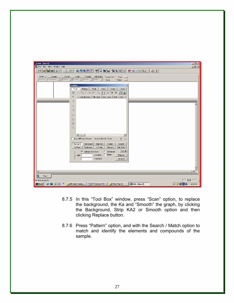
8.7.5 In this “Tool Box” window, press “Scan” option, to replace the background, the Ka and “Smooth” the graph, by clicking the Background, Strip KA2 or Smooth option and then clicking Replace button.
8.7.6 Press “Pattern” option, and with the Search / Match option to
match and identify the elements and compounds of the sample.
27
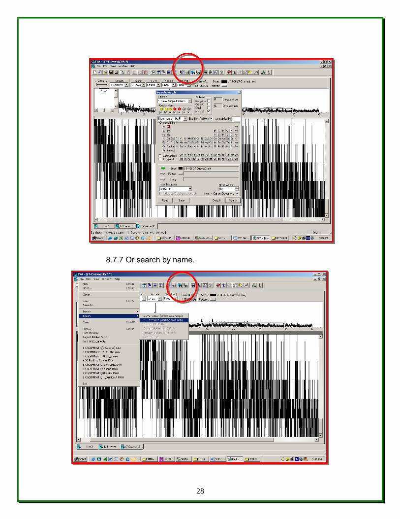
8.7.7 Or search by name.
28
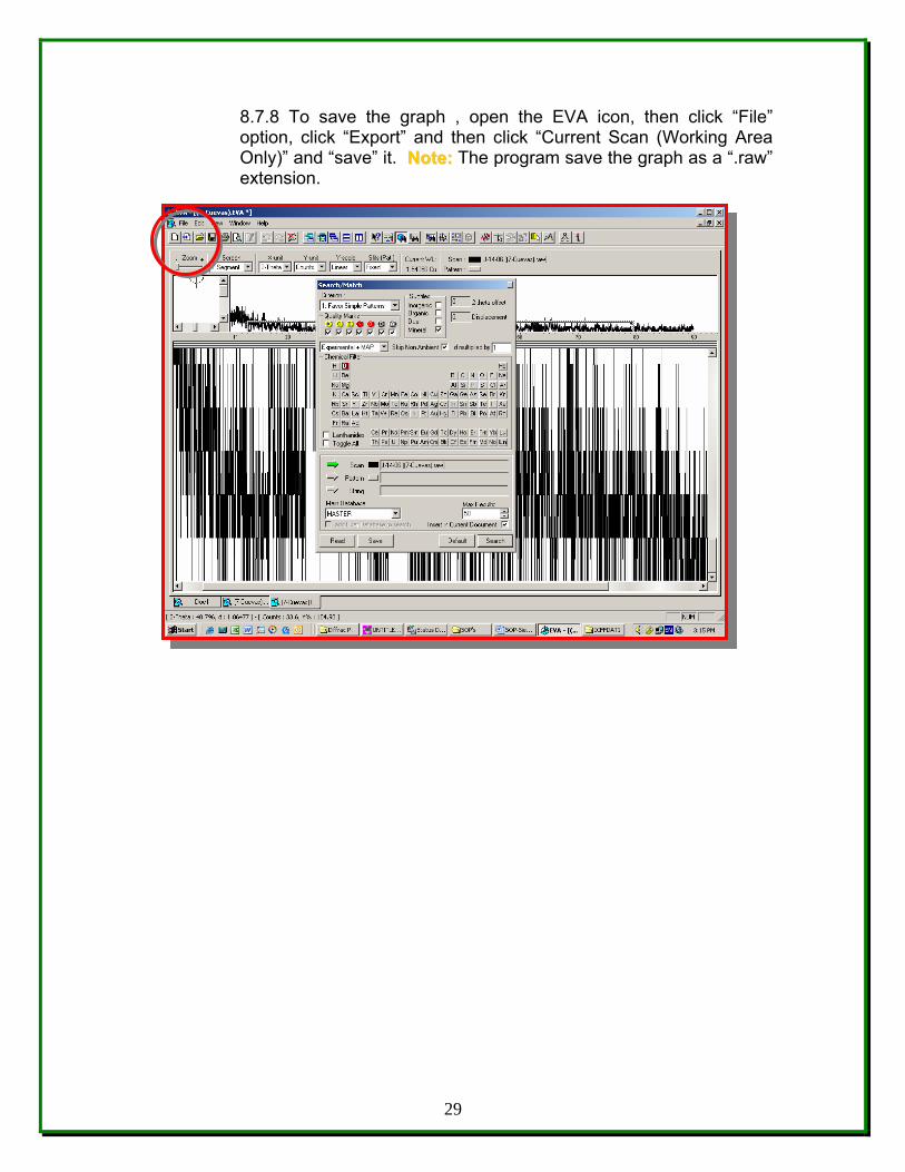
8.7.8 To save the graph , open the EVA icon, then click “File” option, click “Export” and then click “Current Scan (Working Area Only)” and “save” it. NNoottee:: The program save the graph as a “.raw” extension.
29
8.7.9 Go to the “Diffrac Plus Evaluation” to save on an open extension; such as “. xls “ extension.
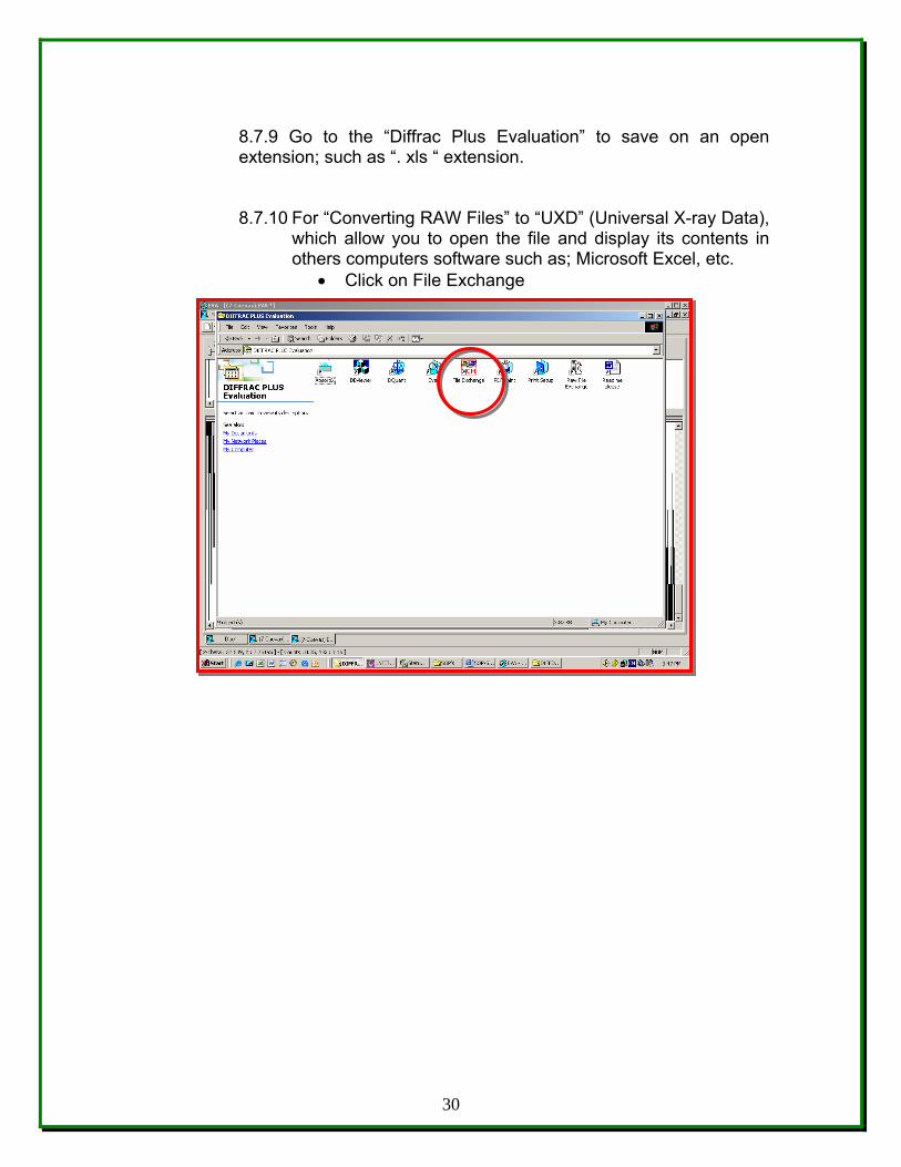
8.7.10 For “Converting RAW Files” to “UXD” (Universal X-ray Data), which allow you to open the file and display its contents in others computers software such as; Microsoft Excel, etc.
• Click on File Exchange
30
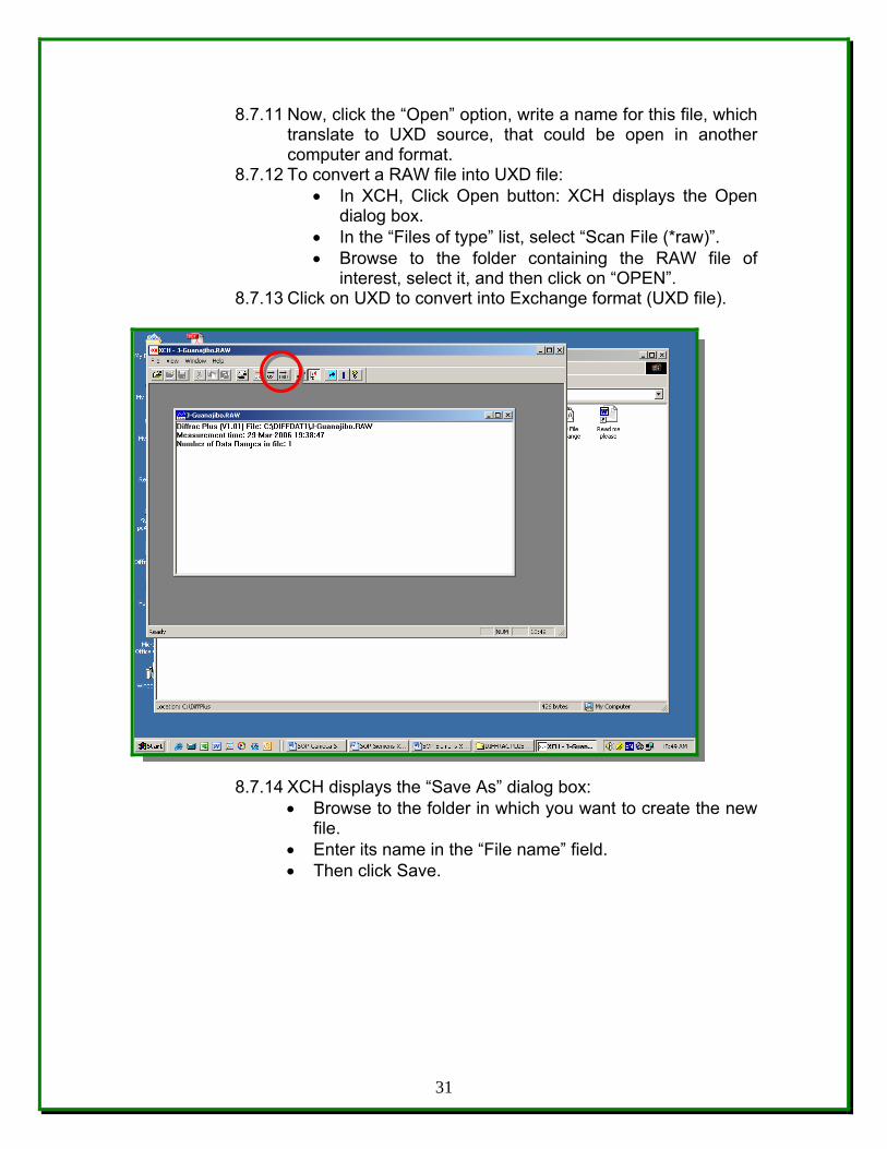
8.7.11 Now, click the “Open” option, write a name for this file, which translate to UXD source, that could be open in another computer and format.
8.7.12 To convert a RAW file into UXD file: • In XCH, Click Open button: XCH displays the Open
dialog box. • In the “Files of type” list, select “Scan File (*raw)”. • Browse to the folder containing the RAW file of
interest, select it, and then click on “OPEN”. 8.7.13 Click on UXD to convert into Exchange format (UXD file).
8.7.14 XCH displays the “Save As” dialog box: • Browse to the folder in which you want to create the new
file. • Enter its name in the “File name” field. • Then click Save.
31
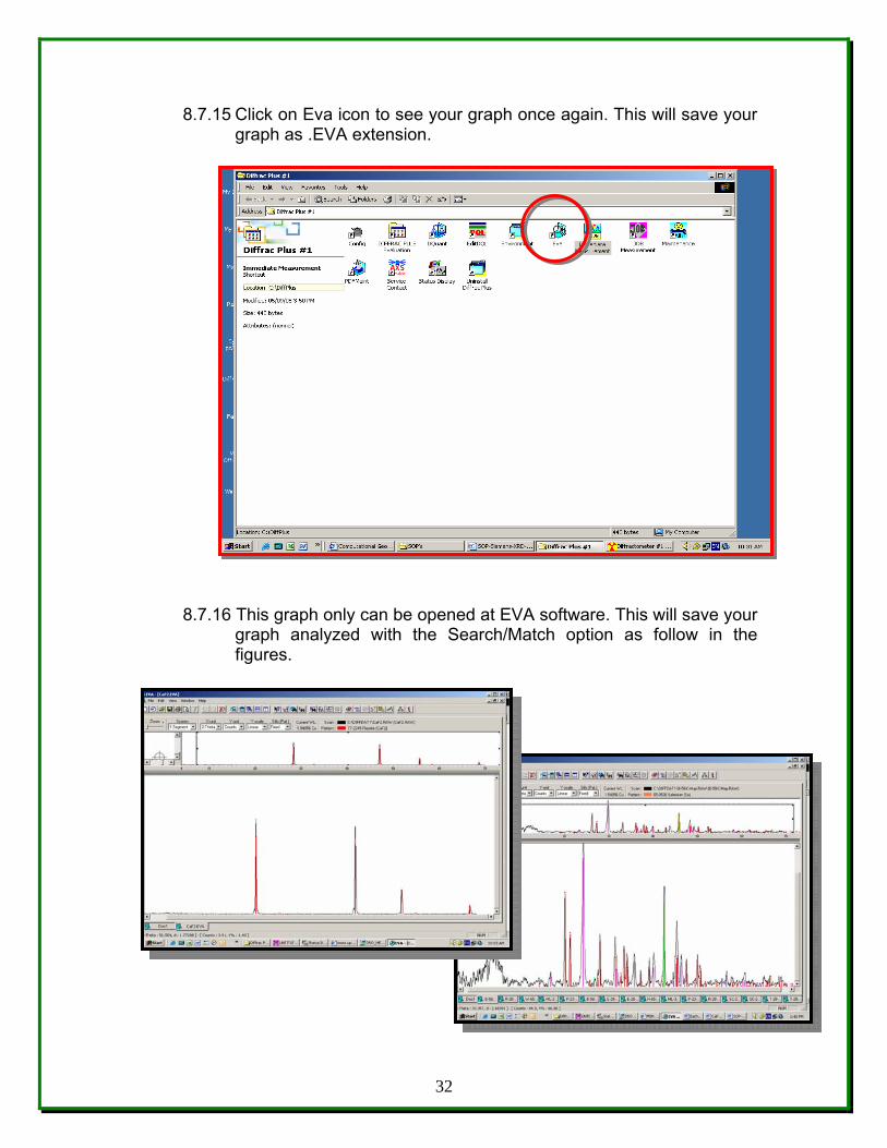
8.7.15 Click on Eva icon to see your graph once again. This will save your graph as .EVA extension.
8.7.16 This graph only can be opened at EVA software. This will save your
graph analyzed with the Search/Match option as follow in the figures.
32
8.8 Potential Sources of Error and Uncertainty – Criteria for recognizing
and evaluating potential sources of error and uncertainty will be indicated by the Procedure User’s inability to obtain a quality image or to generate a semiquantitative or quantitative analysis within tolerance limits. Acceptance criteria for quantitative analysis of Samples are based on acceptable analyses of appropriate standards. Procedure Users may use as a general guide a value of two sigma. That is, if standard analyses are within two sigma (based solely on counting statistics) of the list or published values, then the analysis is acceptable. Procedure Users may define different acceptance criteria.
8.9 Equipment Malfunctions - Malfunction of the Diffraktometer D5000
System is readily detectable by the Machine Custodian during operation of the instrument. If a trained Procedure User has doubts concerning his/her ability to detect equipment malfunction during operation of this equipment, he/she should consult with the Machine Custodian.
8.10 Safety Considerations - Normal operating conditions as performed
by trained Procedure Users present no safety hazards.
8.11 Environmental Conditions - Normal interior building temperature and humidity are acceptable for the operation of the XRD-D5000 System. Cooling water for the XRD-D5000 diffusion pump and electronics chassis is supplied by the building chilled-water system maintained in the range of 55 to 65 degrees Fahrenheit. Ambient air temperature for the XRD-D5000 System should range between 60 and 80 degrees Fahrenheit.. NNoottee:: If environmental conditions move out of range during operating the XRD-D5000 system in WDS mode, Procedure Users should take extra precaution to ensure system stability by checking standards often.
8.12 Calibration of Magnification - The Machine Custodian (or delegated
individual) will check the accuracy of the computer-generated micrometer marker annually against NIST Standard Reference Material Catalog, SEM magnification Standard. Tolerance is + 10%. If out of tolerance, it will be the Machine Custodian’s responsibility to arrange for repair of the instrument so that it will be within tolerance.
33
9.0 RECORDS The Procedure User is responsible for submitting the following records to the Machine Custodian/Lab. Instrumentation specialist to be storage at the UPR-NSF Earth X-ray Analysis Center (EXACt), F-304-C.
9.1 Log-Book or Notebook records of the sample handling and results of analysis relevant to Production of XRD data.
9.2 Data submittals will be storage in the electronic database.
9.3 It is obligation of the user to backup the data obtained.
9.4 Data will be held by the laboratory for thirty (30) days, after which it
may be eliminated from departmental files. 10.0 REFERENCES The following documents have been cited within this procedure by:
• Siemens D5000 X-ray Diffractometer Manual, Siemens Analytical X-Ray Instruments, Inc. 6300 Enterprise Lane, Madison WI, 53719
• Siemens D5000 X-ray Diffractometer Operation and Maintenance – Training Course, Siemens Analytical X-Ray Instruments, Inc. 6300 Enterprise Lane, Madison WI, 53719
• Bruker Advanced X-Ray Solutions; DIFFFRACplus User’s Manual • http://www.bruker-axs.de • http://erproject.lanl.gov/docs/Quality/SOP/SOP-09.02R1T.pdf • http://geology.uprm.edu/facilities/exact.html • http://geology.uprm.edu/facilities/labrules/exact.doc • http://www.ilpi.com/inorganic/glassware/xrd.html • http://www.ilpi.com/inorganic/glassware/mortarpestle.html • http://www.ilpi.com/inorganic/glassware/ballmill.html
34