Embed Size (px)
Citation preview
Vertiguide: Geländerseile Balustrade Cables
NEWS 2002 4544
VS3 VS4 VS5 VS6 VS7 VS8 VS9 VS10 VS11 VS12VS1 VS2
53 5657
58 59 6061
62 63 64 65 6667
47 504849
5152
E E
F F
G G
H H
K KS S
E
F
G
G
G
H
K
K
S
S
S
S
S
K
VERTIGUIDE® VS1–VS12
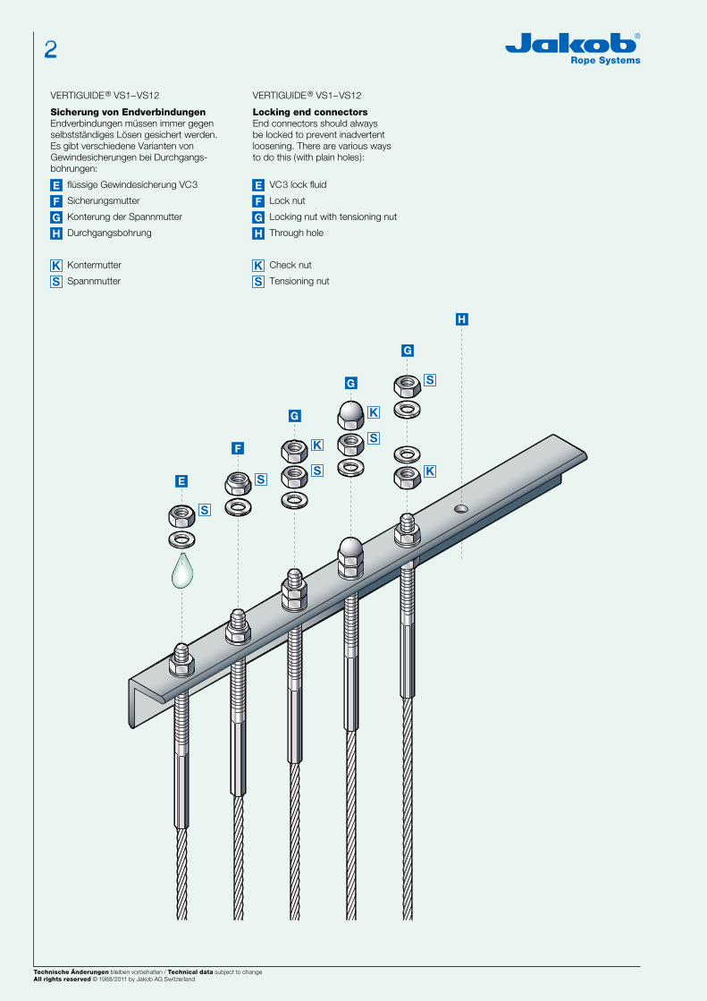
Sicherung von EndverbindungenEndverbindungen müssen immer gegenselbstständiges Lösen gesichert werden.Es gibt verschiedene Varianten von Gewindesicherungen bei Durchgangs-bohrungen:
flüssige Gewindesicherung VC3
Sicherungsmutter
Konterung der Spannmutter
Durchgangsbohrung
Kontermutter
Spannmutter
VERTIGUIDE® VS1–VS12
Locking end connectorsEnd connectors should always be locked to prevent inadvertent loosening. There are various ways to do this (with plain holes):
VC3 lock fluid
Lock nut
Locking nut with tensioning nut
Through hole
Check nut
Tensioning nut
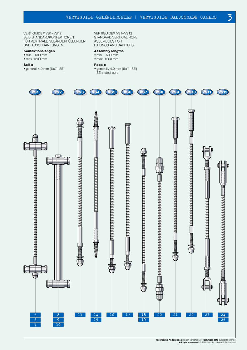
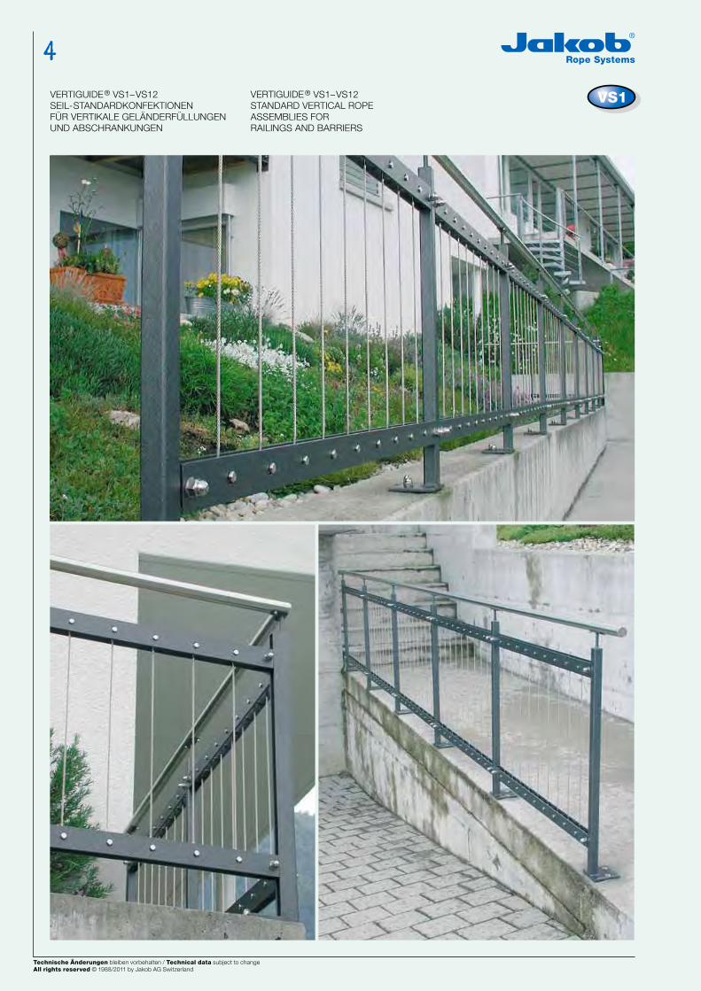
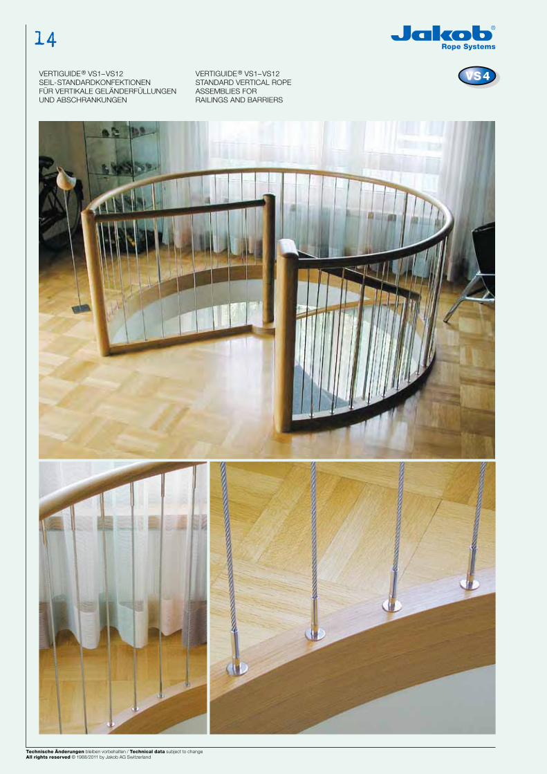
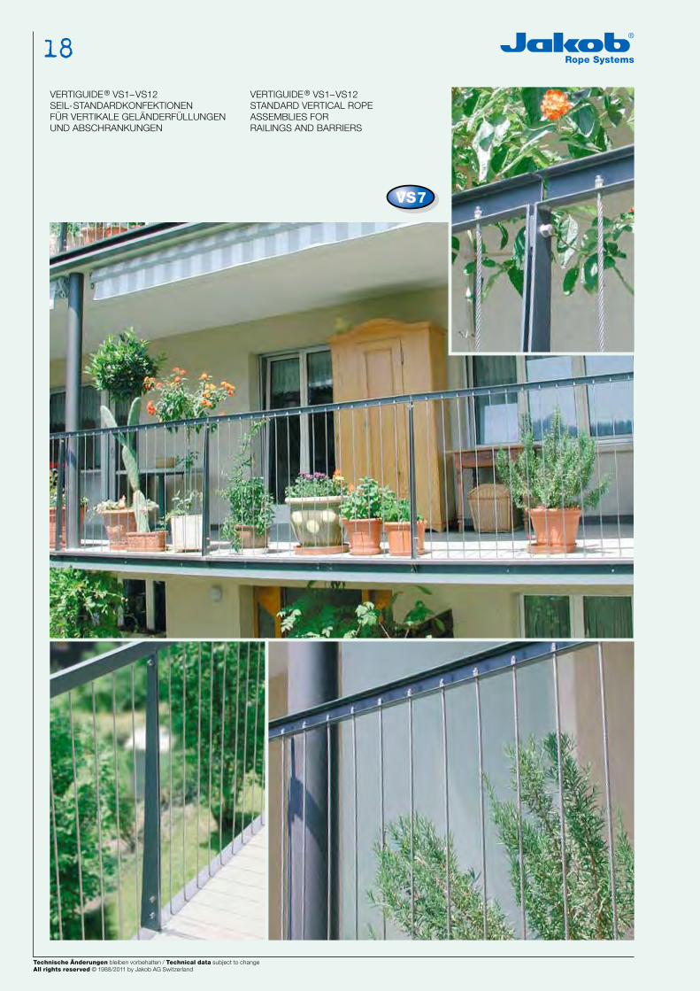
VERTIGUIDE® VS1–VS12SEIL-STANDARDKONFEKTIONEN FÜR VERTIKALE GELÄNDERFÜLLUNGEN UND ABSCHRANKUNGEN
Konfektionslängen • min. 500 mm• max. 1200 mm
Seil-ø • generell 4,0 mm (6x7+ SE)
VERTIGUIDE® VS1–VS12STANDARD VERTICAL ROPE ASSEMBLIES FORRAILINGS AND BARRIERS
Assembly lengths• min. 500 mm• max. 1200 mm
Rope ø• generally 4.0 mm (6x7+ SE )
SE = steel core
Technische Änderungen bleiben vorbehalten / Technical data subject to changeAll rights reserved © 1988/2002 by Jakob AG Switzerland
Technische Änderungen bleiben vorbehalten / Technical data subject to changeAll rights reserved © 1988/2002 by Jakob AG Switzerland Technische Änderungen bleiben vorbehalten / Technical data subject to changeAll rights reserved © 1988/2011 by Jakob AG Switzerland
2
Technische Änderungen bleiben vorbehalten / Technical data subject to changeAll rights reserved © 1988/2011 by Jakob AG Switzerland
NEWS 2002 4544
VS3 VS4 VS5 VS6 VS7 VS8 VS9 VS10 VS11 VS12VS1 VS2
53 5657
58 59 6061
62 63 64 65 6667
47 504849
5152
E E
F F
G G
H H
K KS S
E
F
G
G
G
H
K
K
S
S
S
S
S
K
VERTIGUIDE® VS1–VS12
Sicherung von EndverbindungenEndverbindungen müssen immer gegenselbstständiges Lösen gesichert werden.Es gibt verschiedene Varianten von Gewindesicherungen bei Durchgangs-bohrungen:
flüssige Gewindesicherung VC3
Sicherungsmutter
Konterung der Spannmutter
Durchgangsbohrung
Kontermutter
Spannmutter
VERTIGUIDE® VS1–VS12
Locking end connectorsEnd connectors should always be locked to prevent inadvertent loosening. There are various ways to do this (with plain holes):
VC3 lock fluid
Lock nut
Locking nut with tensioning nut
Through hole
Check nut
Tensioning nut
VERTIGUIDE® VS1–VS12SEIL-STANDARDKONFEKTIONEN FÜR VERTIKALE GELÄNDERFÜLLUNGEN UND ABSCHRANKUNGEN
Konfektionslängen • min. 500 mm• max. 1200 mm
Seil-ø • generell 4,0 mm (6x7+ SE)
VERTIGUIDE® VS1–VS12STANDARD VERTICAL ROPE ASSEMBLIES FORRAILINGS AND BARRIERS
Assembly lengths• min. 500 mm• max. 1200 mm
Rope ø• generally 4.0 mm (6x7+ SE )
SE = steel core
Technische Änderungen bleiben vorbehalten / Technical data subject to changeAll rights reserved © 1988/2002 by Jakob AG Switzerland
Technische Änderungen bleiben vorbehalten / Technical data subject to changeAll rights reserved © 1988/2002 by Jakob AG Switzerland
5 8 11 14 16 17 18 20 21 22 23 246 9 15 19 257 10
Technische Änderungen bleiben vorbehalten / Technical data subject to changeAll rights reserved © 1988/2011 by Jakob AG Switzerland
3 VERTIGUIDE GELÄNDERSEILE | VERTIGUIDE BALUSTRADE CABLES
Technische Änderungen bleiben vorbehalten / Technical data subject to changeAll rights reserved © 1988/2011 by Jakob AG Switzerland
NEWS 2002 4746
b1
c1
c2b6
a
b
ø d1
sw
k
ø d4
ø d2 ø d3
b2
ø d5
b4b3 b5
Rno.
VS1
VS1
NEUNEU
VS1
ø mm
4,0 / 6x7+ SE
20820–
0001
VERTIGUIDE®
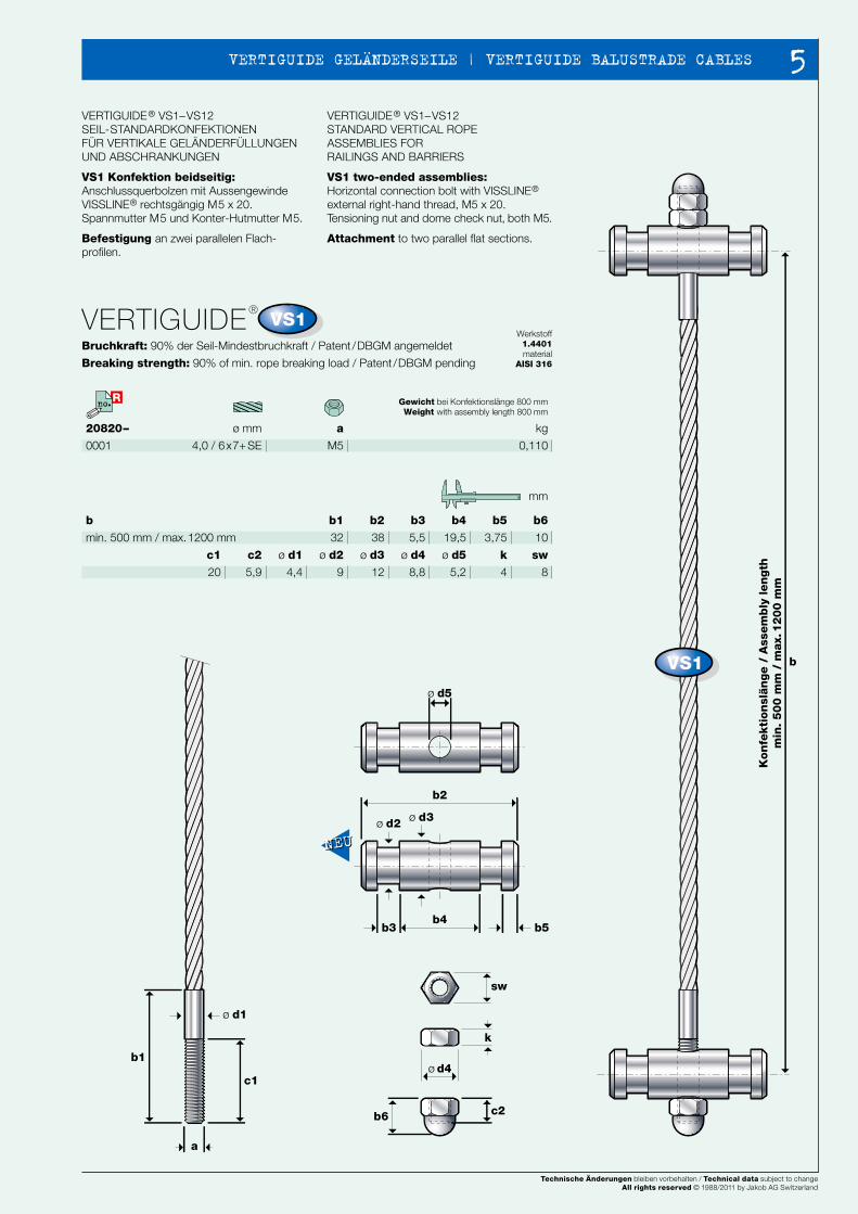
Bruchkraft: 90% der Seil-Mindestbruchkraft / Patent /DBGM angemeldet
Breaking strength: 90% of min. rope breaking load / Patent /DBGM pending
Werkstoff1.4401material
AISI 316
a
M5
VERTIGUIDE® VS1–VS12SEIL-STANDARDKONFEKTIONEN FÜR VERTIKALE GELÄNDERFÜLLUNGEN UND ABSCHRANKUNGEN
VS1 Konfektion beidseitig: Anschlussquerbolzen mit Aussengewinde VISSLINE® rechtsgängig M5 x 20. Spannmutter M5 und Konter-Hutmutter M5.
Befestigung an zwei parallelen Flach-profilen.
VERTIGUIDE® VS1–VS12STANDARD VERTICAL ROPE ASSEMBLIES FORRAILINGS AND BARRIERS
VS1 two-ended assemblies:Horizontal connection bolt with VISSLINE® external right-hand thread, M5 x 20.Tensioning nut and dome check nut, both M5.
Attachment to two parallel flat sections.
b2
38
b3
5,5
b4
19,5
b5
3,75
b6
10
b1
32
b
min. 500 mm / max. 1200 mm
k
4
ø d4
8,8
ø d5
5,2
ø d3
12
ø d2
9
ø d1
4,4
c2
5,9
c1
20
sw
8
mm
Gewicht bei Konfektionslänge 800 mmWeight with assembly length 800 mm
kg
0,110
VERTIGUIDE® VS1–VS12SEIL-STANDARDKONFEKTIONEN FÜR VERTIKALE GELÄNDERFÜLLUNGEN UND ABSCHRANKUNGEN
VERTIGUIDE® VS1–VS12STANDARD VERTICAL ROPE ASSEMBLIES FORRAILINGS AND BARRIERS
Kon
fekti
on
slän
ge /
Ass
em
bly
len
gth
min
. 5
00
mm
/ m
ax.
12
00
mm
Technische Änderungen bleiben vorbehalten / Technical data subject to changeAll rights reserved © 1988/2002 by Jakob AG Switzerland
Technische Änderungen bleiben vorbehalten / Technical data subject to changeAll rights reserved © 1988/2002 by Jakob AG Switzerland Technische Änderungen bleiben vorbehalten / Technical data subject to changeAll rights reserved © 1988/2011 by Jakob AG Switzerland
4
NEWS 2002 4746
b1
c1
c2b6
a
b
ø d1
sw
k
ø d4
ø d2 ø d3
b2
ø d5
b4b3 b5
Rno.
VS1
VS1
NEUNEU
VS1
ø mm
4,0 / 6x7+ SE
20820–
0001
VERTIGUIDE®
Bruchkraft: 90% der Seil-Mindestbruchkraft / Patent /DBGM angemeldet
Breaking strength: 90% of min. rope breaking load / Patent /DBGM pending
Werkstoff1.4401material
AISI 316
a
M5
VERTIGUIDE® VS1–VS12SEIL-STANDARDKONFEKTIONEN FÜR VERTIKALE GELÄNDERFÜLLUNGEN UND ABSCHRANKUNGEN
VS1 Konfektion beidseitig: Anschlussquerbolzen mit Aussengewinde VISSLINE® rechtsgängig M5 x 20. Spannmutter M5 und Konter-Hutmutter M5.
Befestigung an zwei parallelen Flach-profilen.
VERTIGUIDE® VS1–VS12STANDARD VERTICAL ROPE ASSEMBLIES FORRAILINGS AND BARRIERS
VS1 two-ended assemblies:Horizontal connection bolt with VISSLINE® external right-hand thread, M5 x 20.Tensioning nut and dome check nut, both M5.
Attachment to two parallel flat sections.
b2
38
b3
5,5
b4
19,5
b5
3,75
b6
10
b1
32
b
min. 500 mm / max. 1200 mm
k
4
ø d4
8,8
ø d5
5,2
ø d3
12
ø d2
9
ø d1
4,4
c2
5,9
c1
20
sw
8
mm
Gewicht bei Konfektionslänge 800 mmWeight with assembly length 800 mm
kg
0,110
VERTIGUIDE® VS1–VS12SEIL-STANDARDKONFEKTIONEN FÜR VERTIKALE GELÄNDERFÜLLUNGEN UND ABSCHRANKUNGEN
VERTIGUIDE® VS1–VS12STANDARD VERTICAL ROPE ASSEMBLIES FORRAILINGS AND BARRIERS
Kon
fekti
on
slän
ge /
Ass
em
bly
len
gth
min
. 5
00
mm
/ m
ax.
12
00
mm
Technische Änderungen bleiben vorbehalten / Technical data subject to changeAll rights reserved © 1988/2002 by Jakob AG Switzerland
Technische Änderungen bleiben vorbehalten / Technical data subject to changeAll rights reserved © 1988/2002 by Jakob AG Switzerland
Technische Änderungen bleiben vorbehalten / Technical data subject to changeAll rights reserved © 1988/2011 by Jakob AG Switzerland
5 VERTIGUIDE GELÄNDERSEILE | VERTIGUIDE BALUSTRADE CABLES
NEWS 2002 4948
R R
B
A
xx
K
ø 13,5
H
A
α
2,25
xx
2,25
KL800 mm
f = 11 mm
HF = 30 N (3 kg) Fq
A
A
VS1 VS1
VERTIGUIDE® VS1–VS12SEIL-STANDARDKONFEKTIONEN FÜR VERTIKALE GELÄNDERFÜLLUNGEN UND ABSCHRANKUNGEN
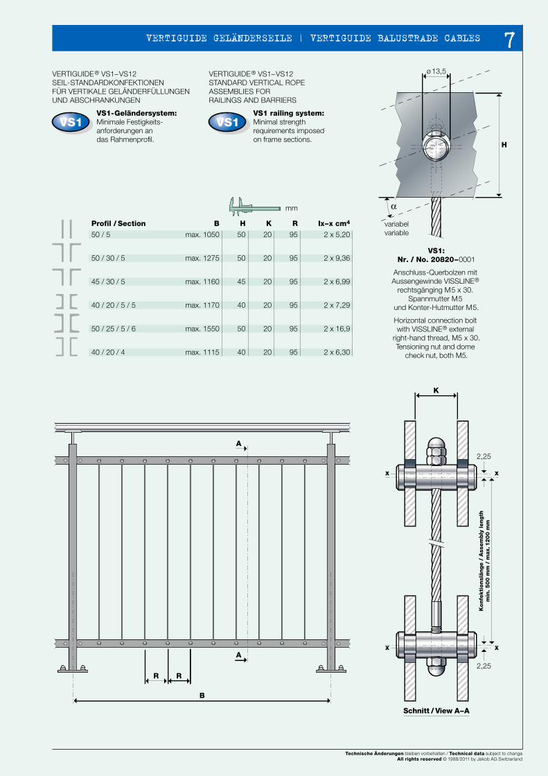
VS1-Geländersystem: Minimale Festigkeits-anforderungen andas Rahmenprofil.
H
50
50
45
40
50
40
K
20
20
20
20
20
20
R
95
95
95
95
95
95
Ix–x cm4
2 x 5,20
2 x 9,36
2 x 6,99
2 x 7,29
2 x 16,9
2 x 6,30
B
max. 1050
max. 1275
max. 1160
max. 1170
max. 1550
max. 1115
Profil / Section
50 / 5
50 / 30 / 5
45 / 30 / 5
40 / 20 / 5 / 5
50 / 25 / 5 / 6
40 / 20 / 4
mm
VERTIGUIDE® VS1–VS12STANDARD VERTICAL ROPE ASSEMBLIES FORRAILINGS AND BARRIERS
VS1 railing system:Minimal strength requirements imposed on frame sections.
VS1:Nr. / No. 20820–0001
Anschluss-Querbolzen mit Aussengewinde VISSLINE®
rechtsgänging M5 x 30. Spannmutter M5
und Konter-Hutmutter M5.
Horizontal connection bolt with VISSLINE® external
right-hand thread, M5 x 30.Tensioning nut and dome
check nut, both M5.
VERTIGUIDE® VS1–VS12SEIL-STANDARDKONFEKTIONEN FÜR VERTIKALE GELÄNDERFÜLLUNGEN UND ABSCHRANKUNGEN
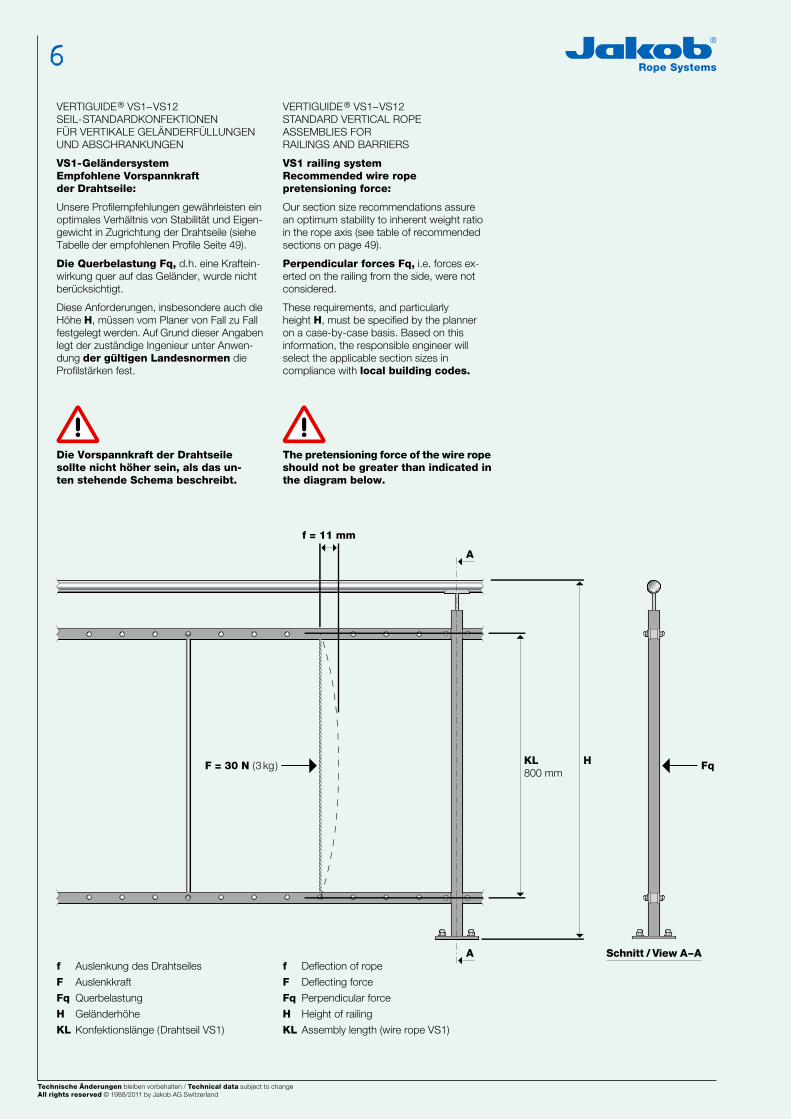
VS1-GeländersystemEmpfohlene Vorspannkraft der Drahtseile:
Unsere Profilempfehlungen gewährleisten ein optimales Verhältnis von Stabilität und Eigen-gewicht in Zugrichtung der Drahtseile (siehe Tabelle der empfohlenen Profile Seite 49).
Die Querbelastung Fq, d.h. eine Kraftein-wirkung quer auf das Geländer, wurde nicht berücksichtigt.
Diese Anforderungen, insbesondere auch die Höhe H, müssen vom Planer von Fall zu Fall festgelegt werden. Auf Grund dieser Angaben legt der zuständige Ingenieur unter Anwen-dung der gültigen Landesnormen die Profilstärken fest.
VERTIGUIDE® VS1–VS12STANDARD VERTICAL ROPE ASSEMBLIES FORRAILINGS AND BARRIERS
VS1 railing systemRecommended wire rope pretensioning force:
Our section size recommendations assure an optimum stability to inherent weight ratio in the rope axis (see table of recommended sections on page 49).
Perpendicular forces Fq, i.e. forces ex-erted on the railing from the side, were not considered.
These requirements, and particularly height H, must be specified by the planner on a case-by-case basis. Based on this information, the responsible engineer will select the applicable section sizes in compliance with local building codes.
f Auslenkung des Drahtseiles
F Auslenkkraft
Fq Querbelastung
H Geländerhöhe
KL Konfektionslänge (Drahtseil VS1)
f Deflection of rope
F Deflecting force
Fq Perpendicular force
H Height of railing
KL Assembly length (wire rope VS1)
Die Vorspannkraft der Drahtseile sollte nicht höher sein, als das un-ten stehende Schema beschreibt.
The pretensioning force of the wire rope should not be greater than indicated in the diagram below.
Konfe
kti
onsl
änge /
Ass
em
bly
length
min
. 500 m
m /
max.
12
00 m
m
variabelvariable
Schnitt / View A–A
Schnitt / View A–A
Technische Änderungen bleiben vorbehalten / Technical data subject to changeAll rights reserved © 1988/2003 by Jakob AG Switzerland. Rev.1
Technische Änderungen bleiben vorbehalten / Technical data subject to changeAll rights reserved © 1988/2002 by Jakob AG Switzerland Technische Änderungen bleiben vorbehalten / Technical data subject to changeAll rights reserved © 1988/2011 by Jakob AG Switzerland
6
NEWS 2002 4948
R R
B
A
xx
K
ø 13,5
H
A
α
2,25
xx
2,25
KL800 mm
f = 11 mm
HF = 30 N (3 kg) Fq
A
A
VS1 VS1
VERTIGUIDE® VS1–VS12SEIL-STANDARDKONFEKTIONEN FÜR VERTIKALE GELÄNDERFÜLLUNGEN UND ABSCHRANKUNGEN
VS1-Geländersystem: Minimale Festigkeits-anforderungen andas Rahmenprofil.
H
50
50
45
40
50
40
K
20
20
20
20
20
20
R
95
95
95
95
95
95
Ix–x cm4
2 x 5,20
2 x 9,36
2 x 6,99
2 x 7,29
2 x 16,9
2 x 6,30
B
max. 1050
max. 1275
max. 1160
max. 1170
max. 1550
max. 1115
Profil / Section
50 / 5
50 / 30 / 5
45 / 30 / 5
40 / 20 / 5 / 5
50 / 25 / 5 / 6
40 / 20 / 4
mm
VERTIGUIDE® VS1–VS12STANDARD VERTICAL ROPE ASSEMBLIES FORRAILINGS AND BARRIERS
VS1 railing system:Minimal strength requirements imposed on frame sections.
VS1:Nr. / No. 20820–0001
Anschluss-Querbolzen mit Aussengewinde VISSLINE®
rechtsgänging M5 x 30. Spannmutter M5
und Konter-Hutmutter M5.
Horizontal connection bolt with VISSLINE® external
right-hand thread, M5 x 30.Tensioning nut and dome
check nut, both M5.
VERTIGUIDE® VS1–VS12SEIL-STANDARDKONFEKTIONEN FÜR VERTIKALE GELÄNDERFÜLLUNGEN UND ABSCHRANKUNGEN
VS1-GeländersystemEmpfohlene Vorspannkraft der Drahtseile:
Unsere Profilempfehlungen gewährleisten ein optimales Verhältnis von Stabilität und Eigen-gewicht in Zugrichtung der Drahtseile (siehe Tabelle der empfohlenen Profile Seite 49).
Die Querbelastung Fq, d.h. eine Kraftein-wirkung quer auf das Geländer, wurde nicht berücksichtigt.
Diese Anforderungen, insbesondere auch die Höhe H, müssen vom Planer von Fall zu Fall festgelegt werden. Auf Grund dieser Angaben legt der zuständige Ingenieur unter Anwen-dung der gültigen Landesnormen die Profilstärken fest.
VERTIGUIDE® VS1–VS12STANDARD VERTICAL ROPE ASSEMBLIES FORRAILINGS AND BARRIERS
VS1 railing systemRecommended wire rope pretensioning force:
Our section size recommendations assure an optimum stability to inherent weight ratio in the rope axis (see table of recommended sections on page 49).
Perpendicular forces Fq, i.e. forces ex-erted on the railing from the side, were not considered.
These requirements, and particularly height H, must be specified by the planner on a case-by-case basis. Based on this information, the responsible engineer will select the applicable section sizes in compliance with local building codes.
f Auslenkung des Drahtseiles
F Auslenkkraft
Fq Querbelastung
H Geländerhöhe
KL Konfektionslänge (Drahtseil VS1)
f Deflection of rope
F Deflecting force
Fq Perpendicular force
H Height of railing
KL Assembly length (wire rope VS1)
Die Vorspannkraft der Drahtseile sollte nicht höher sein, als das un-ten stehende Schema beschreibt.
The pretensioning force of the wire rope should not be greater than indicated in the diagram below.
Konfe
kti
onsl
änge /
Ass
em
bly
length
min
. 500 m
m /
max.
12
00 m
m
variabelvariable
Schnitt / View A–A
Schnitt / View A–A
Technische Änderungen bleiben vorbehalten / Technical data subject to changeAll rights reserved © 1988/2003 by Jakob AG Switzerland. Rev.1
Technische Änderungen bleiben vorbehalten / Technical data subject to changeAll rights reserved © 1988/2002 by Jakob AG Switzerland
Technische Änderungen bleiben vorbehalten / Technical data subject to changeAll rights reserved © 1988/2011 by Jakob AG Switzerland
7 VERTIGUIDE GELÄNDERSEILE | VERTIGUIDE BALUSTRADE CABLES
NEWS 2002 5150
b
ø d2 ø d3
b1
b3b2 b4
ø d1
c1
ø d3
a
k
ø d4
b5
a
c2
Rno.
VS2
VS12VS2
NEU NEUNEU NEU
VS1
VS2
20820–
0002
VERTIGUIDE®
Patent /DBGM angemeldet / Patent /DBGM pending Werkstoff / material
1.4404 / AISI 316
a
M5
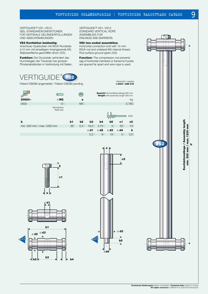
VERTIGUIDE® VS1–VS12SEIL-STANDARDKONFEKTIONEN FÜR VERTIKALE GELÄNDERFÜLLUNGEN UND ABSCHRANKUNGEN
VS2 Konfektion beidseitig: Anschluss-Querbolzen mit INOX-Rundstab ø12 mm mit einseitigem Innengewinde M5.Staboberfläche geschliffen (Korn 220).
Funktion: Der Druckstab verhindert das Durchbiegen der Traversen bei grossen Pfostenabständen in Verbindung mit Seilen.
VERTIGUIDE® VS1–VS12STANDARD VERTICAL ROPE ASSEMBLIES FORRAILINGS AND BARRIERS
VS2 two-ended assemblies:Horizontal connection bolt with 12-mm INOX rod and unilateral M5 internal thread.Rod surface ground (grain 220).
Function: The compression rod prevents sag of horizontal members or transoms if posts are spaced far apart and wire rope is used.
b1
38
b2
5,5
b3
19,5
b4
3,75
b5
5
c1
20
c2
10
b
min. 500 mm / max. 1200 mm
k
3,5
ø d1
5,2
ø d3
12
ø d4
5
ø d2
9
mm
Gewicht bei Konfektionslänge 800 mmWeight with assembly length 800 mm
kg
0,780
VERTIGUIDE® VS1–VS12SEIL-STANDARDKONFEKTIONEN FÜR VERTIKALE GELÄNDERFÜLLUNGEN UND ABSCHRANKUNGEN
VERTIGUIDE® VS1–VS12STANDARD VERTICAL ROPE ASSEMBLIES FORRAILINGS AND BARRIERS
ø NG
12Nenngrösse
Ratet size
Kon
fekti
on
slän
ge /
Ass
em
bly
len
gth
min
. 5
00
mm
/ m
ax.
12
00
mm
Technische Änderungen bleiben vorbehalten / Technical data subject to changeAll rights reserved © 1988/2002 by Jakob AG Switzerland
Technische Änderungen bleiben vorbehalten / Technical data subject to changeAll rights reserved © 1988/2002 by Jakob AG Switzerland Technische Änderungen bleiben vorbehalten / Technical data subject to changeAll rights reserved © 1988/2011 by Jakob AG Switzerland
8
NEWS 2002 5150
b
ø d2 ø d3
b1
b3b2 b4
ø d1
c1
ø d3
a
k
ø d4
b5
a
c2
Rno.
VS2
VS12VS2
NEU NEUNEU NEU
VS1
VS2
20820–
0002
VERTIGUIDE®
Patent /DBGM angemeldet / Patent /DBGM pending Werkstoff / material
1.4404 / AISI 316
a
M5
VERTIGUIDE® VS1–VS12SEIL-STANDARDKONFEKTIONEN FÜR VERTIKALE GELÄNDERFÜLLUNGEN UND ABSCHRANKUNGEN
VS2 Konfektion beidseitig: Anschluss-Querbolzen mit INOX-Rundstab ø12 mm mit einseitigem Innengewinde M5.Staboberfläche geschliffen (Korn 220).
Funktion: Der Druckstab verhindert das Durchbiegen der Traversen bei grossen Pfostenabständen in Verbindung mit Seilen.
VERTIGUIDE® VS1–VS12STANDARD VERTICAL ROPE ASSEMBLIES FORRAILINGS AND BARRIERS
VS2 two-ended assemblies:Horizontal connection bolt with 12-mm INOX rod and unilateral M5 internal thread.Rod surface ground (grain 220).
Function: The compression rod prevents sag of horizontal members or transoms if posts are spaced far apart and wire rope is used.
b1
38
b2
5,5
b3
19,5
b4
3,75
b5
5
c1
20
c2
10
b
min. 500 mm / max. 1200 mm
k
3,5
ø d1
5,2
ø d3
12
ø d4
5
ø d2
9
mm
Gewicht bei Konfektionslänge 800 mmWeight with assembly length 800 mm
kg
0,780
VERTIGUIDE® VS1–VS12SEIL-STANDARDKONFEKTIONEN FÜR VERTIKALE GELÄNDERFÜLLUNGEN UND ABSCHRANKUNGEN
VERTIGUIDE® VS1–VS12STANDARD VERTICAL ROPE ASSEMBLIES FORRAILINGS AND BARRIERS
ø NG
12Nenngrösse
Ratet size
Kon
fekti
on
slän
ge /
Ass
em
bly
len
gth
min
. 5
00
mm
/ m
ax.
12
00
mm
Technische Änderungen bleiben vorbehalten / Technical data subject to changeAll rights reserved © 1988/2002 by Jakob AG Switzerland
Technische Änderungen bleiben vorbehalten / Technical data subject to changeAll rights reserved © 1988/2002 by Jakob AG Switzerland
Technische Änderungen bleiben vorbehalten / Technical data subject to changeAll rights reserved © 1988/2011 by Jakob AG Switzerland
9 VERTIGUIDE GELÄNDERSEILE | VERTIGUIDE BALUSTRADE CABLES
NEWS 2002 5352
R R VS2
B B
A
K
xx
K
2,25
xx
2,25
b1
c1
c2b2
ø d1
a
sw
ø d2
k
ø d3
3lx
ø13
b1
b1
b
R
R
H
α
ø 13,5
A
Rno.
VS2 VS2
VS3
VS3
R
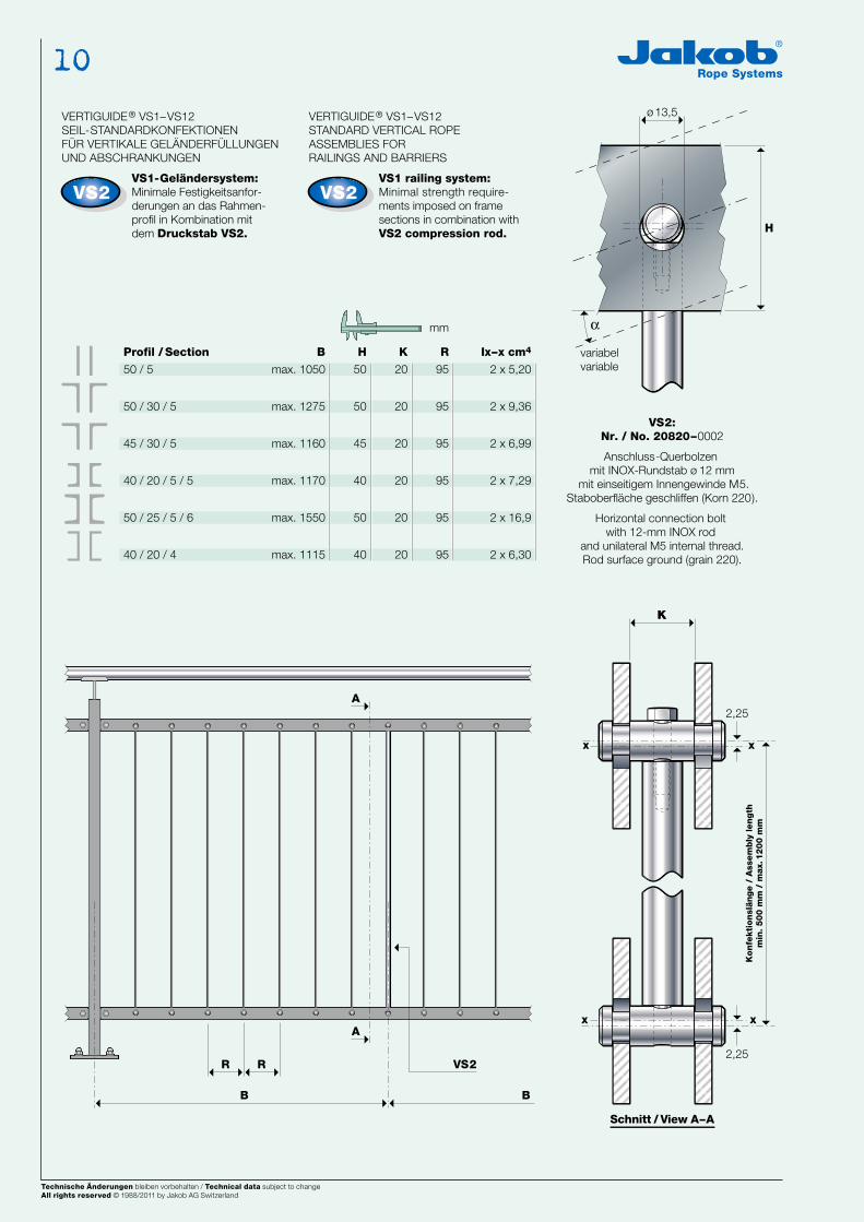
VERTIGUIDE® VS1–VS12SEIL-STANDARDKONFEKTIONEN FÜR VERTIKALE GELÄNDERFÜLLUNGEN UND ABSCHRANKUNGEN
VS1-Geländersystem: Minimale Festigkeitsanfor-derungen an das Rahmen- profil in Kombination mitdem Druckstab VS2.
VERTIGUIDE® VS1–VS12STANDARD VERTICAL ROPE ASSEMBLIES FORRAILINGS AND BARRIERS
VS1 railing system:Minimal strength require-ments imposed on frame sections in combination with VS2 compression rod.
VS2:Nr. / No. 20820–0002
Anschluss-Querbolzen mit INOX-Rundstab ø 12 mm
mit einseitigem Innengewinde M5.Staboberfläche geschliffen (Korn 220).
Horizontal connection bolt with 12-mm INOX rod
and unilateral M5 internal thread.Rod surface ground (grain 220).
H
50
50
45
40
50
40
K
20
20
20
20
20
20
R
95
95
95
95
95
95
Ix–x cm4
2 x 5,20
2 x 9,36
2 x 6,99
2 x 7,29
2 x 16,9
2 x 6,30
B
max. 1050
max. 1275
max. 1160
max. 1170
max. 1550
max. 1115
Profil / Section
50 / 5
50 / 30 / 5
45 / 30 / 5
40 / 20 / 5 / 5
50 / 25 / 5 / 6
40 / 20 / 4
mm
Gewicht bei Konfektionslänge 800 mmWeight with assembly length 800 mm
kg
0,078
0,090
ø mm
4,0 / 6x7+ SE
20820–
0003
0003–01 (mit zwei Formanschlüssen / with two post fittings)
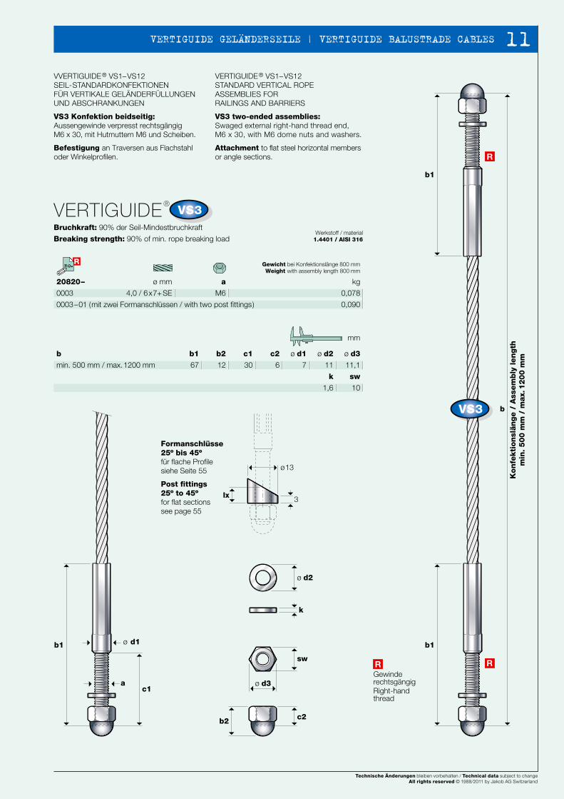
VERTIGUIDE®
Bruchkraft: 90% der Seil-Mindestbruchkraft
Breaking strength: 90% of min. rope breaking loadWerkstoff / material
1.4401 / AISI 316
a
M6
VVERTIGUIDE® VS1–VS12SEIL-STANDARDKONFEKTIONEN FÜR VERTIKALE GELÄNDERFÜLLUNGEN UND ABSCHRANKUNGEN
VS3 Konfektion beidseitig: Aussengewinde verpresst rechtsgängigM6 x 30, mit Hutmuttern M6 und Scheiben.
Befestigung an Traversen aus Flachstahl oder Winkelprofilen.
VERTIGUIDE® VS1–VS12STANDARD VERTICAL ROPE ASSEMBLIES FORRAILINGS AND BARRIERS
VS3 two-ended assemblies:Swaged external right-hand thread end,M6 x 30, with M6 dome nuts and washers.
Attachment to flat steel horizontal members or angle sections.
ø d1
7
ø d2
11
ø d3
11,1
c2
6
b2
12
c1
30
b1
67
b
min. 500 mm / max. 1200 mm
k
1,6
sw
10
mm
Formanschlüsse25º bis 45º für flache Profilesiehe Seite 55
Post fittings25º to 45ºfor flat sections see page 55
Gewinde rechtsgängig Right-hand thread
Konfe
kti
onsl
änge /
Ass
em
bly
length
min
. 500 m
m /
max.
1200 m
m
Kon
fekti
on
slän
ge /
Ass
em
bly
len
gth
min
. 5
00
mm
/ m
ax.
12
00
mm
Schnitt / View A–A
variabelvariable
Technische Änderungen bleiben vorbehalten / Technical data subject to changeAll rights reserved © 1988/2002 by Jakob AG Switzerland
Technische Änderungen bleiben vorbehalten / Technical data subject to changeAll rights reserved © 1988/2002 by Jakob AG Switzerland Technische Änderungen bleiben vorbehalten / Technical data subject to changeAll rights reserved © 1988/2011 by Jakob AG Switzerland
10
NEWS 2002 5352
R R VS2
B B
A
K
xx
K
2,25
xx
2,25
b1
c1
c2b2
ø d1
a
sw
ø d2
k
ø d3
3lx
ø13
b1
b1
b
R
R
H
α
ø 13,5
A
Rno.
VS2 VS2
VS3
VS3
R
VERTIGUIDE® VS1–VS12SEIL-STANDARDKONFEKTIONEN FÜR VERTIKALE GELÄNDERFÜLLUNGEN UND ABSCHRANKUNGEN
VS1-Geländersystem: Minimale Festigkeitsanfor-derungen an das Rahmen- profil in Kombination mitdem Druckstab VS2.
VERTIGUIDE® VS1–VS12STANDARD VERTICAL ROPE ASSEMBLIES FORRAILINGS AND BARRIERS
VS1 railing system:Minimal strength require-ments imposed on frame sections in combination with VS2 compression rod.
VS2:Nr. / No. 20820–0002
Anschluss-Querbolzen mit INOX-Rundstab ø 12 mm
mit einseitigem Innengewinde M5.Staboberfläche geschliffen (Korn 220).
Horizontal connection bolt with 12-mm INOX rod
and unilateral M5 internal thread.Rod surface ground (grain 220).
H
50
50
45
40
50
40
K
20
20
20
20
20
20
R
95
95
95
95
95
95
Ix–x cm4
2 x 5,20
2 x 9,36
2 x 6,99
2 x 7,29
2 x 16,9
2 x 6,30
B
max. 1050
max. 1275
max. 1160
max. 1170
max. 1550
max. 1115
Profil / Section
50 / 5
50 / 30 / 5
45 / 30 / 5
40 / 20 / 5 / 5
50 / 25 / 5 / 6
40 / 20 / 4
mm
Gewicht bei Konfektionslänge 800 mmWeight with assembly length 800 mm
kg
0,078
0,090
ø mm
4,0 / 6x7+ SE
20820–
0003
0003–01 (mit zwei Formanschlüssen / with two post fittings)
VERTIGUIDE®
Bruchkraft: 90% der Seil-Mindestbruchkraft
Breaking strength: 90% of min. rope breaking loadWerkstoff / material
1.4401 / AISI 316
a
M6
VVERTIGUIDE® VS1–VS12SEIL-STANDARDKONFEKTIONEN FÜR VERTIKALE GELÄNDERFÜLLUNGEN UND ABSCHRANKUNGEN
VS3 Konfektion beidseitig: Aussengewinde verpresst rechtsgängigM6 x 30, mit Hutmuttern M6 und Scheiben.
Befestigung an Traversen aus Flachstahl oder Winkelprofilen.
VERTIGUIDE® VS1–VS12STANDARD VERTICAL ROPE ASSEMBLIES FORRAILINGS AND BARRIERS
VS3 two-ended assemblies:Swaged external right-hand thread end,M6 x 30, with M6 dome nuts and washers.
Attachment to flat steel horizontal members or angle sections.
ø d1
7
ø d2
11
ø d3
11,1
c2
6
b2
12
c1
30
b1
67
b
min. 500 mm / max. 1200 mm
k
1,6
sw
10
mm
Formanschlüsse25º bis 45º für flache Profilesiehe Seite 55
Post fittings25º to 45ºfor flat sections see page 55
Gewinde rechtsgängig Right-hand thread
Konfe
kti
onsl
änge /
Ass
em
bly
length
min
. 500 m
m /
max.
1200 m
m
Kon
fekti
on
slän
ge /
Ass
em
bly
len
gth
min
. 5
00
mm
/ m
ax.
12
00
mm
Schnitt / View A–A
variabelvariable
Technische Änderungen bleiben vorbehalten / Technical data subject to changeAll rights reserved © 1988/2002 by Jakob AG Switzerland
Technische Änderungen bleiben vorbehalten / Technical data subject to changeAll rights reserved © 1988/2002 by Jakob AG Switzerland
Technische Änderungen bleiben vorbehalten / Technical data subject to changeAll rights reserved © 1988/2011 by Jakob AG Switzerland
11 VERTIGUIDE GELÄNDERSEILE | VERTIGUIDE BALUSTRADE CABLES
NEWS 2002 5554
ø d2
ø d1
lx
l1
α
α 30º
b2
lx
b1
c
α 30º
b2 b1
lx
c
lx
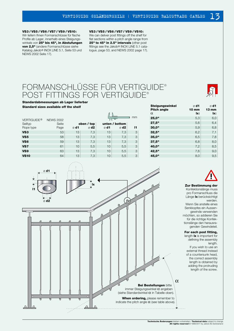
cVS3 / VS5 / VS6 / VS7 / VS9 / VS10: Wir liefern Ihnen Formanschlüsse für flache Profile ab Lager, innerhalb eines Steigungs-winkels von 25º bis 45º, in Abstufungen von 2,5º (andere Formanschlüsse siehe Katalog Jakob® INOX LINE 5.1, Seite 53 und NEWS 2002 Seite 17).
VS3 / VS5 / VS6 / VS7 / VS9 / VS10: We can deliver post fittings off the shelf for flat sections within a pitch angle range from 25º to 45º in 2.5º intervals (other post fittings see the Jakob® INOX LINE 5.1 cata-logue, page 53, and NEWS 2002 page 17).
VERTIGUIDE®
SeiltypRope type
VS3
VS5
VS6
VS7
VS9
VS10
NEWS 2002SeitePage
53
58
59
61
63
64
ø d1
13
13
13
10
13
13
oben / topø d2
7,3
7,3
7,3
5,5
7,3
7,3
unten / bottomø d2
7,3
7,3
7,3
5,5
5,5
5,5
l1
3
3
3
3
3
3
ø d1
13
13
13
10
10
10
SteigungswinkelPitch angleα25,0º
27,5º
30,0º
32,5º
35,0º
37,5º
40,0º
42,5º
45,0º
ø d110 mm
lx:
5,3
5,6
5,9
6,2
6,5
6,8
7,2
7,6
8,0
ø d113 mm
lx:
6,0
6,4
6,8
7,1
7,8
8,0
8,5
9,0
9,5
mm
FORMANSCHLÜSSE FÜR VERTIGUIDE®
POST FITTINGS FOR VERTIGUIDE®
Standardabmessungen ab Lager lieferbar
Standard sizes available off the shelf
Zur Bestimmung derKonfektionslänge muss pro Formanschluss die
Länge lx berücksichtigt werden.
Wenn Sie anstelle einesSenkkopfes ein Aussen-
gewinde verwenden möchten, so addieren Sie
für die richtige Konfek-tionslänge den herausra-
genden Gewindeteil.
For each post fitting, length lx is important for
defining the assembly length.
If you wish to use an external thread instead of a countersunk head,
the correct assembly length is obtained by
adding the protruding length of the screw.
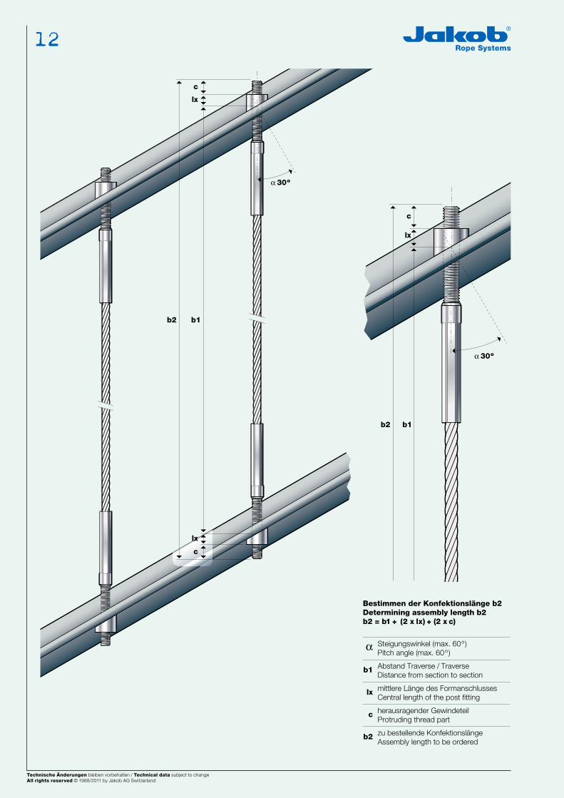
Bestimmen der Konfektionslänge b2Determining assembly length b2b2 = b1 + (2 x lx) + (2 x c)
α Steigungswinkel (max. 60º )Pitch angle (max. 60º )
b1 Abstand Traverse / TraverseDistance from section to section
lx mittlere Länge des FormanschlussesCentral length of the post fitting
c herausragender GewindeteilProtruding thread part
b2 zu bestellende KonfektionslängeAssembly length to be ordered
Bei Bestellungen bitte immer Steigungswinkel α angeben
(siehe Standardwinkel α in Tabelle oben).
When ordering, please remember to indicate the pitch angle α (see table above).
Technische Änderungen bleiben vorbehalten / Technical data subject to changeAll rights reserved © 1988/2002 by Jakob AG Switzerland
Technische Änderungen bleiben vorbehalten / Technical data subject to changeAll rights reserved © 1988/2002 by Jakob AG Switzerland Technische Änderungen bleiben vorbehalten / Technical data subject to changeAll rights reserved © 1988/2011 by Jakob AG Switzerland
12
NEWS 2002 5554
ø d2
ø d1
lx
l1
α
α 30º
b2
lx
b1
c
α 30º
b2 b1
lx
c
lx
cVS3 / VS5 / VS6 / VS7 / VS9 / VS10: Wir liefern Ihnen Formanschlüsse für flache Profile ab Lager, innerhalb eines Steigungs-winkels von 25º bis 45º, in Abstufungen von 2,5º (andere Formanschlüsse siehe Katalog Jakob® INOX LINE 5.1, Seite 53 und NEWS 2002 Seite 17).
VS3 / VS5 / VS6 / VS7 / VS9 / VS10: We can deliver post fittings off the shelf for flat sections within a pitch angle range from 25º to 45º in 2.5º intervals (other post fittings see the Jakob® INOX LINE 5.1 cata-logue, page 53, and NEWS 2002 page 17).
VERTIGUIDE®
SeiltypRope type
VS3
VS5
VS6
VS7
VS9
VS10
NEWS 2002SeitePage
53
58
59
61
63
64
ø d1
13
13
13
10
13
13
oben / topø d2
7,3
7,3
7,3
5,5
7,3
7,3
unten / bottomø d2
7,3
7,3
7,3
5,5
5,5
5,5
l1
3
3
3
3
3
3
ø d1
13
13
13
10
10
10
SteigungswinkelPitch angleα25,0º
27,5º
30,0º
32,5º
35,0º
37,5º
40,0º
42,5º
45,0º
ø d110 mm
lx:
5,3
5,6
5,9
6,2
6,5
6,8
7,2
7,6
8,0
ø d113 mm
lx:
6,0
6,4
6,8
7,1
7,8
8,0
8,5
9,0
9,5
mm
FORMANSCHLÜSSE FÜR VERTIGUIDE®
POST FITTINGS FOR VERTIGUIDE®
Standardabmessungen ab Lager lieferbar
Standard sizes available off the shelf
Zur Bestimmung derKonfektionslänge muss pro Formanschluss die
Länge lx berücksichtigt werden.
Wenn Sie anstelle einesSenkkopfes ein Aussen-
gewinde verwenden möchten, so addieren Sie
für die richtige Konfek-tionslänge den herausra-
genden Gewindeteil.
For each post fitting, length lx is important for
defining the assembly length.
If you wish to use an external thread instead of a countersunk head,
the correct assembly length is obtained by
adding the protruding length of the screw.
Bestimmen der Konfektionslänge b2Determining assembly length b2b2 = b1 + (2 x lx) + (2 x c)
α Steigungswinkel (max. 60º )Pitch angle (max. 60º )
b1 Abstand Traverse / TraverseDistance from section to section
lx mittlere Länge des FormanschlussesCentral length of the post fitting
c herausragender GewindeteilProtruding thread part
b2 zu bestellende KonfektionslängeAssembly length to be ordered
Bei Bestellungen bitte immer Steigungswinkel α angeben
(siehe Standardwinkel α in Tabelle oben).
When ordering, please remember to indicate the pitch angle α (see table above).
Technische Änderungen bleiben vorbehalten / Technical data subject to changeAll rights reserved © 1988/2002 by Jakob AG Switzerland
Technische Änderungen bleiben vorbehalten / Technical data subject to changeAll rights reserved © 1988/2002 by Jakob AG Switzerland
Technische Änderungen bleiben vorbehalten / Technical data subject to changeAll rights reserved © 1988/2011 by Jakob AG Switzerland
13 VERTIGUIDE GELÄNDERSEILE | VERTIGUIDE BALUSTRADE CABLES
NEWS 2002 5756
b1
b1
b1
b2
c1
k
a
ø d2
c2
c3
5
b
a
ø d1
R
L
Rno.
NEUNEU
VS4
VS4
L
R
VS4
ø mm
4,0 / 6x7+ SE
20820–
0004
VERTIGUIDE®
Bruchkraft: 90% der Seil-Mindestbruchkraft
Breaking strength: 90% of min. rope breaking loadWerkstoff / material
1.4401 / AISI 316
a
M6
VERTIGUIDE® VS1–VS12SEIL-STANDARDKONFEKTIONEN FÜR VERTIKALE GELÄNDERFÜLLUNGEN UND ABSCHRANKUNGEN
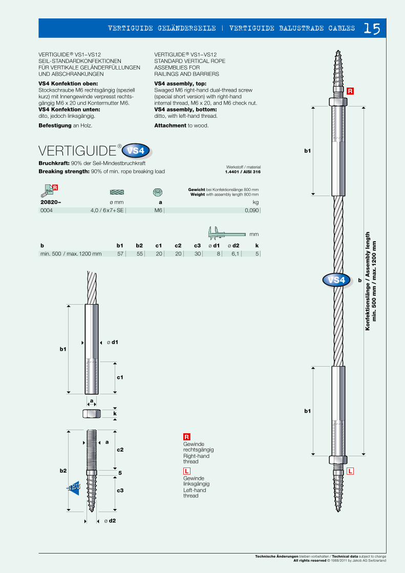
VS4 Konfektion oben: Stockschraube M6 rechtsgängig (speziell kurz) mit Innengewinde verpresst rechts-gängig M6 x 20 und Kontermutter M6.VS4 Konfektion unten: dito, jedoch linksgängig.
Befestigung an Holz.
VERTIGUIDE® VS1–VS12STANDARD VERTICAL ROPE ASSEMBLIES FORRAILINGS AND BARRIERS
VS4 assembly, top:Swaged M6 right-hand dual-thread screw (special short version) with right-hand internal thread, M6 x 20, and M6 check nut.VS4 assembly, bottom:ditto, with left-hand thread.
Attachment to wood.
ø d2
6,1
k
5
ø d1
8
b2
55
c1
20
c2
20
c3
30
b1
57
b
min. 500 / max. 1200 mm
mm
Gewinde linksgängig Left-hand thread
Gewinde rechtsgängig Right-hand thread
Gewicht bei Konfektionslänge 800 mmWeight with assembly length 800 mm
kg
0,090
VERTIGUIDE® VS1–VS12SEIL-STANDARDKONFEKTIONEN FÜR VERTIKALE GELÄNDERFÜLLUNGEN UND ABSCHRANKUNGEN
VERTIGUIDE® VS1–VS12STANDARD VERTICAL ROPE ASSEMBLIES FORRAILINGS AND BARRIERS
Kon
fekti
on
slän
ge /
Ass
em
bly
len
gth
min
. 5
00
mm
/ m
ax.
12
00
mm
Technische Änderungen bleiben vorbehalten / Technical data subject to changeAll rights reserved © 1988/2002 by Jakob AG Switzerland
Technische Änderungen bleiben vorbehalten / Technical data subject to changeAll rights reserved © 1988/2002 by Jakob AG Switzerland Technische Änderungen bleiben vorbehalten / Technical data subject to changeAll rights reserved © 1988/2011 by Jakob AG Switzerland
14
NEWS 2002 5756
b1
b1
b1
b2
c1
k
a
ø d2
c2
c3
5
b
a
ø d1
R
L
Rno.
NEUNEU
VS4
VS4
L
R
VS4
ø mm
4,0 / 6x7+ SE
20820–
0004
VERTIGUIDE®
Bruchkraft: 90% der Seil-Mindestbruchkraft
Breaking strength: 90% of min. rope breaking loadWerkstoff / material
1.4401 / AISI 316
a
M6
VERTIGUIDE® VS1–VS12SEIL-STANDARDKONFEKTIONEN FÜR VERTIKALE GELÄNDERFÜLLUNGEN UND ABSCHRANKUNGEN
VS4 Konfektion oben: Stockschraube M6 rechtsgängig (speziell kurz) mit Innengewinde verpresst rechts-gängig M6 x 20 und Kontermutter M6.VS4 Konfektion unten: dito, jedoch linksgängig.
Befestigung an Holz.
VERTIGUIDE® VS1–VS12STANDARD VERTICAL ROPE ASSEMBLIES FORRAILINGS AND BARRIERS
VS4 assembly, top:Swaged M6 right-hand dual-thread screw (special short version) with right-hand internal thread, M6 x 20, and M6 check nut.VS4 assembly, bottom:ditto, with left-hand thread.
Attachment to wood.
ø d2
6,1
k
5
ø d1
8
b2
55
c1
20
c2
20
c3
30
b1
57
b
min. 500 / max. 1200 mm
mm
Gewinde linksgängig Left-hand thread
Gewinde rechtsgängig Right-hand thread
Gewicht bei Konfektionslänge 800 mmWeight with assembly length 800 mm
kg
0,090
VERTIGUIDE® VS1–VS12SEIL-STANDARDKONFEKTIONEN FÜR VERTIKALE GELÄNDERFÜLLUNGEN UND ABSCHRANKUNGEN
VERTIGUIDE® VS1–VS12STANDARD VERTICAL ROPE ASSEMBLIES FORRAILINGS AND BARRIERS
Kon
fekti
on
slän
ge /
Ass
em
bly
len
gth
min
. 5
00
mm
/ m
ax.
12
00
mm
Technische Änderungen bleiben vorbehalten / Technical data subject to changeAll rights reserved © 1988/2002 by Jakob AG Switzerland
Technische Änderungen bleiben vorbehalten / Technical data subject to changeAll rights reserved © 1988/2002 by Jakob AG Switzerland
Technische Änderungen bleiben vorbehalten / Technical data subject to changeAll rights reserved © 1988/2011 by Jakob AG Switzerland
15 VERTIGUIDE GELÄNDERSEILE | VERTIGUIDE BALUSTRADE CABLES
NEWS 2002 5958
b1
b3b3
c1
c2b4
a
b
ø d3
sw
ø d4
k2
ø d2
b2b1
ø d1
r
k1
R
ø d5
3lx
ø13
b1
b3b3
c1
c2b4
b
ø d2
ø d3
b2b1
ø d190°
k1k2
sw
ø d4
k3
ø d5R
3lx
ø13
a
R Rno.no.
VS5
VS5
R
VS6
VS6
R
ø mm
4,0 / 6x7+ SE
20820–
0005
0005–01 (mit zwei Formanschlüssen / with two post fittings)
VERTIGUIDE®
Bruchkraft: 90% der Seil-Mindestbruchkraft
Breaking strength: 90% of min. rope breaking loadWerkstoff / material
1.4401 / AISI 316
a
M6
VERTIGUIDE® VS1–VS12SEIL-STANDARDKONFEKTIONEN FÜR VERTIKALE GELÄNDERFÜLLUNGEN UND ABSCHRANKUNGEN
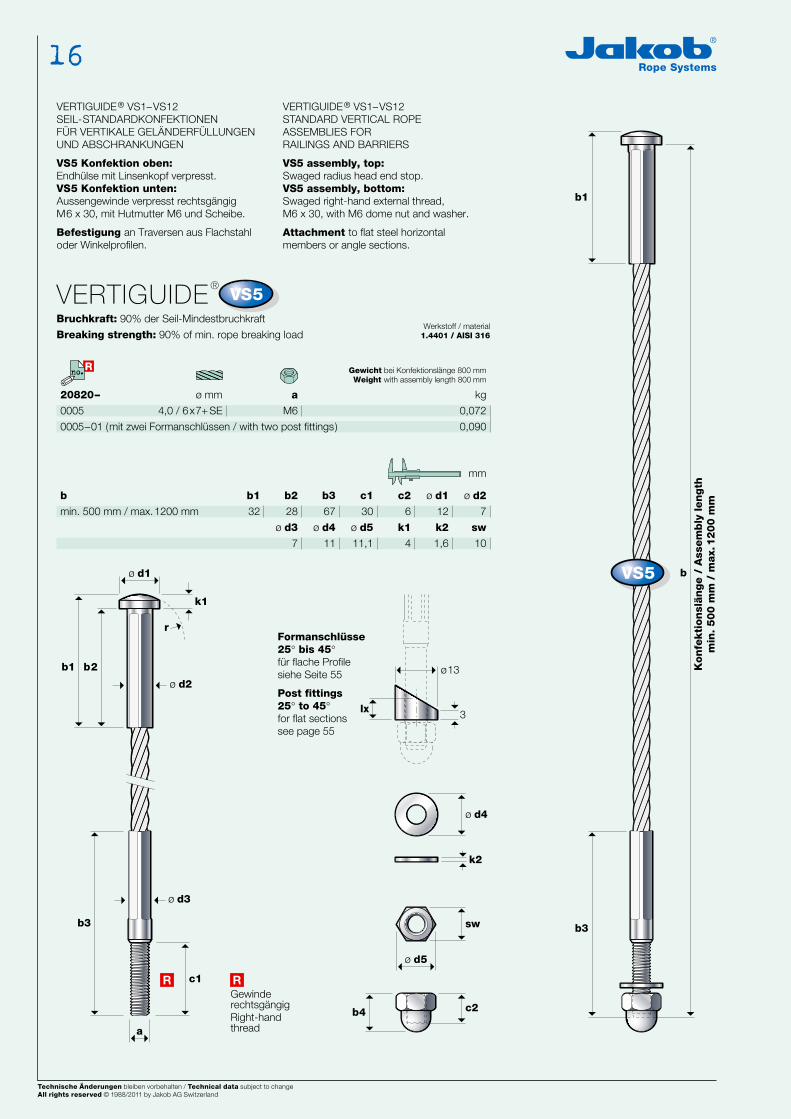
VS5 Konfektion oben:Endhülse mit Linsenkopf verpresst.VS5 Konfektion unten:Aussengewinde verpresst rechtsgängigM6 x 30, mit Hutmutter M6 und Scheibe.
Befestigung an Traversen aus Flachstahl oder Winkelprofilen.
VERTIGUIDE® VS1–VS12STANDARD VERTICAL ROPE ASSEMBLIES FORRAILINGS AND BARRIERS
VS5 assembly, top:Swaged radius head end stop.VS5 assembly, bottom:Swaged right-hand external thread, M6 x 30, with M6 dome nut and washer.
Attachment to flat steel horizontal members or angle sections.
ø d1
12
ø d2
7
c2
6
b2
28
b3
67
c1
30
b1
32
b
min. 500 mm / max. 1200 mm
k2
1,6
k1
4
ø d4
11
ø d5
11,1
ø d3
7
sw
10
mm
GewinderechtsgängigRight-handthread
Gewicht bei Konfektionslänge 800 mmWeight with assembly length 800 mm
kg
0,072
0,090
Formanschlüsse25° bis 45°für flache Profilesiehe Seite 55
Post fittings25° to 45°for flat sections see page 55
ø mm
4,0 / 6x7+ SE
20820–
0006
0006–01 (mit zwei Formanschlüssen / with two post fittings)
VERTIGUIDE®
Bruchkraft: 90% der Seil-Mindestbruchkraft
Breaking strength: 90% of min. rope breaking loadWerkstoff / material
1.4401 / AISI 316
a
M6
VERTIGUIDE® VS1–VS12SEIL-STANDARDKONFEKTIONEN FÜR VERTIKALE GELÄNDERFÜLLUNGEN UND ABSCHRANKUNGEN
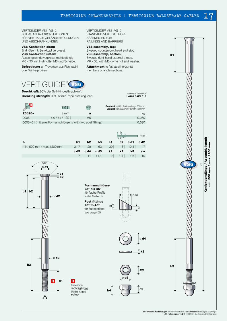
VS6 Konfektion oben:Endhülse mit Senkkopf verpresst.VS6 Konfektion unten:Aussengewinde verpresst rechtsgängigM6 x 30, mit Hutmutter M6 und Scheibe.
Befestigung an Traversen aus Flachstahl oder Winkelprofilen.
VERTIGUIDE® VS1–VS12STANDARD VERTICAL ROPE ASSEMBLIES FORRAILINGS AND BARRIERS
VS6 assembly, top:Swaged countersunk head end stop.VS6 assembly, bottom:Swaged right-hand external thread, M6 x 30, with M6 dome nut and washer.
Attachment to flat steel horizontal members or angle sections.
ø d1
10,4
ø d2
7
c2
6
b2
28
b3
63
c1
30
b1
31,7
b
min. 500 mm / max. 1200 mm
k3
1,6
k2
1,7
k1
2
ø d4
11
ø d5
11,1
ø d3
7
sw
10
mm
GewinderechtsgängigRight-handthread
Gewicht bei Konfektionslänge 800 mmWeight with assembly length 800 mm
kg
0,070
0,080
Formanschlüsse25° bis 45°für flache Profilesiehe Seite 55
Post fittings25° to 45°for flat sections see page 55
Kon
fekti
on
slän
ge
/ A
ssem
bly
len
gth
min
. 5
00
mm
/ m
ax.
12
00
mm
Kon
fekti
on
slän
ge
/ A
ssem
bly
len
gth
min
. 5
00
mm
/ m
ax.
12
00
mm
Technische Änderungen bleiben vorbehalten / Technical data subject to changeAll rights reserved © 1988/2005 by Jakob AG Switzerland. Rev. 2
Technische Änderungen bleiben vorbehalten / Technical data subject to changeAll rights reserved © 1988/2003 by Jakob AG Switzerland. Ref.1Technische Änderungen bleiben vorbehalten / Technical data subject to changeAll rights reserved © 1988/2011 by Jakob AG Switzerland
16
NEWS 2002 5958
b1
b3b3
c1
c2b4
a
b
ø d3
sw
ø d4
k2
ø d2
b2b1
ø d1
r
k1
R
ø d5
3lx
ø13
b1
b3b3
c1
c2b4
b
ø d2
ø d3
b2b1
ø d190°
k1k2
sw
ø d4
k3
ø d5R
3lx
ø13
a
R Rno.no.
VS5
VS5
R
VS6
VS6
R
ø mm
4,0 / 6x7+ SE
20820–
0005
0005–01 (mit zwei Formanschlüssen / with two post fittings)
VERTIGUIDE®
Bruchkraft: 90% der Seil-Mindestbruchkraft
Breaking strength: 90% of min. rope breaking loadWerkstoff / material
1.4401 / AISI 316
a
M6
VERTIGUIDE® VS1–VS12SEIL-STANDARDKONFEKTIONEN FÜR VERTIKALE GELÄNDERFÜLLUNGEN UND ABSCHRANKUNGEN
VS5 Konfektion oben:Endhülse mit Linsenkopf verpresst.VS5 Konfektion unten:Aussengewinde verpresst rechtsgängigM6 x 30, mit Hutmutter M6 und Scheibe.
Befestigung an Traversen aus Flachstahl oder Winkelprofilen.
VERTIGUIDE® VS1–VS12STANDARD VERTICAL ROPE ASSEMBLIES FORRAILINGS AND BARRIERS
VS5 assembly, top:Swaged radius head end stop.VS5 assembly, bottom:Swaged right-hand external thread, M6 x 30, with M6 dome nut and washer.
Attachment to flat steel horizontal members or angle sections.
ø d1
12
ø d2
7
c2
6
b2
28
b3
67
c1
30
b1
32
b
min. 500 mm / max. 1200 mm
k2
1,6
k1
4
ø d4
11
ø d5
11,1
ø d3
7
sw
10
mm
GewinderechtsgängigRight-handthread
Gewicht bei Konfektionslänge 800 mmWeight with assembly length 800 mm
kg
0,072
0,090
Formanschlüsse25° bis 45°für flache Profilesiehe Seite 55
Post fittings25° to 45°for flat sections see page 55
ø mm
4,0 / 6x7+ SE
20820–
0006
0006–01 (mit zwei Formanschlüssen / with two post fittings)
VERTIGUIDE®
Bruchkraft: 90% der Seil-Mindestbruchkraft
Breaking strength: 90% of min. rope breaking loadWerkstoff / material
1.4401 / AISI 316
a
M6
VERTIGUIDE® VS1–VS12SEIL-STANDARDKONFEKTIONEN FÜR VERTIKALE GELÄNDERFÜLLUNGEN UND ABSCHRANKUNGEN
VS6 Konfektion oben:Endhülse mit Senkkopf verpresst.VS6 Konfektion unten:Aussengewinde verpresst rechtsgängigM6 x 30, mit Hutmutter M6 und Scheibe.
Befestigung an Traversen aus Flachstahl oder Winkelprofilen.
VERTIGUIDE® VS1–VS12STANDARD VERTICAL ROPE ASSEMBLIES FORRAILINGS AND BARRIERS
VS6 assembly, top:Swaged countersunk head end stop.VS6 assembly, bottom:Swaged right-hand external thread, M6 x 30, with M6 dome nut and washer.
Attachment to flat steel horizontal members or angle sections.
ø d1
10,4
ø d2
7
c2
6
b2
28
b3
63
c1
30
b1
31,7
b
min. 500 mm / max. 1200 mm
k3
1,6
k2
1,7
k1
2
ø d4
11
ø d5
11,1
ø d3
7
sw
10
mm
GewinderechtsgängigRight-handthread
Gewicht bei Konfektionslänge 800 mmWeight with assembly length 800 mm
kg
0,070
0,080
Formanschlüsse25° bis 45°für flache Profilesiehe Seite 55
Post fittings25° to 45°for flat sections see page 55
Kon
fekti
on
slän
ge
/ A
ssem
bly
len
gth
min
. 5
00
mm
/ m
ax.
12
00
mm
Kon
fekti
on
slän
ge
/ A
ssem
bly
len
gth
min
. 5
00
mm
/ m
ax.
12
00
mm
Technische Änderungen bleiben vorbehalten / Technical data subject to changeAll rights reserved © 1988/2005 by Jakob AG Switzerland. Rev. 2
Technische Änderungen bleiben vorbehalten / Technical data subject to changeAll rights reserved © 1988/2003 by Jakob AG Switzerland. Ref.1
Technische Änderungen bleiben vorbehalten / Technical data subject to changeAll rights reserved © 1988/2011 by Jakob AG Switzerland
17 VERTIGUIDE GELÄNDERSEILE | VERTIGUIDE BALUSTRADE CABLES
NEWS 2002 6160
b1
b1
b
ø d2
k
b1
c1
c2b2
a
ø d1
sw
ø d3
3lx
ø10
Rno.
VS7
VS7
R R
VS7
ø mm
4,0 / 6x7+ SE
20820–
0007
0007–01 (mit zwei Formanschlüssen / with two post fittings)
VERTIGUIDE®
Bruchkraft: 90% der Seil-Mindestbruchkraft
Breaking strength: 90% of min. rope breaking loadWerkstoff / material
1.4401 / AISI 316
a
M5
VERTIGUIDE® VS1–VS12SEIL-STANDARDKONFEKTIONEN FÜR VERTIKALE GELÄNDERFÜLLUNGEN UND ABSCHRANKUNGEN
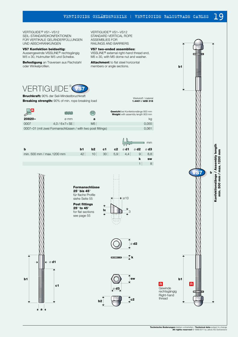
VS7 Konfektion beidseitig: Aussengewinde VISSLINE® rechtsgängig M5 x 30, Hutmutter M5 und Scheibe.
Befestigung an Traversen aus Flachstahl oder Winkelprofilen.
VERTIGUIDE® VS1–VS12STANDARD VERTICAL ROPE ASSEMBLIES FORRAILINGS AND BARRIERS
VS7 two-ended assemblies:VISSLINE® external right-hand thread end,M5 x 30, with M5 dome nut and washer.
Attachment to flat steel horizontal members or angle sections.
ø d2
9
ø d3
8,8
ø d1
4,4
b2
10
c1
30
c2
5,9
b1
42
b
min. 500 mm / max. 1200 mm
k
1
sw
8
mm
Gewinde rechtsgängig Right-hand thread
Gewicht bei Konfektionslänge 800 mmWeight with assembly length 800 mm
kg
0,055
0,061
Formanschlüsse25° bis 45° für flache Profilesiehe Seite 55
Post fittings25° to 45°for flat sections see page 55
VERTIGUIDE® VS1–VS12SEIL-STANDARDKONFEKTIONEN FÜR VERTIKALE GELÄNDERFÜLLUNGEN UND ABSCHRANKUNGEN
VERTIGUIDE® VS1–VS12STANDARD VERTICAL ROPE ASSEMBLIES FORRAILINGS AND BARRIERS
Kon
fekti
on
slän
ge /
Ass
em
bly
len
gth
min
. 5
00
mm
/ m
ax.
12
00
mm
Technische Änderungen bleiben vorbehalten / Technical data subject to changeAll rights reserved © 1988/2002 by Jakob AG Switzerland
Technische Änderungen bleiben vorbehalten / Technical data subject to changeAll rights reserved © 1988/2002 by Jakob AG Switzerland Technische Änderungen bleiben vorbehalten / Technical data subject to changeAll rights reserved © 1988/2011 by Jakob AG Switzerland
18
NEWS 2002 6160
b1
b1
b
ø d2
k
b1
c1
c2b2
a
ø d1
sw
ø d3
3lx
ø10
Rno.
VS7
VS7
R R
VS7
ø mm
4,0 / 6x7+ SE
20820–
0007
0007–01 (mit zwei Formanschlüssen / with two post fittings)
VERTIGUIDE®
Bruchkraft: 90% der Seil-Mindestbruchkraft
Breaking strength: 90% of min. rope breaking loadWerkstoff / material
1.4401 / AISI 316
a
M5
VERTIGUIDE® VS1–VS12SEIL-STANDARDKONFEKTIONEN FÜR VERTIKALE GELÄNDERFÜLLUNGEN UND ABSCHRANKUNGEN
VS7 Konfektion beidseitig: Aussengewinde VISSLINE® rechtsgängig M5 x 30, Hutmutter M5 und Scheibe.
Befestigung an Traversen aus Flachstahl oder Winkelprofilen.
VERTIGUIDE® VS1–VS12STANDARD VERTICAL ROPE ASSEMBLIES FORRAILINGS AND BARRIERS
VS7 two-ended assemblies:VISSLINE® external right-hand thread end,M5 x 30, with M5 dome nut and washer.
Attachment to flat steel horizontal members or angle sections.
ø d2
9
ø d3
8,8
ø d1
4,4
b2
10
c1
30
c2
5,9
b1
42
b
min. 500 mm / max. 1200 mm
k
1
sw
8
mm
Gewinde rechtsgängig Right-hand thread
Gewicht bei Konfektionslänge 800 mmWeight with assembly length 800 mm
kg
0,055
0,061
Formanschlüsse25° bis 45° für flache Profilesiehe Seite 55
Post fittings25° to 45°for flat sections see page 55
VERTIGUIDE® VS1–VS12SEIL-STANDARDKONFEKTIONEN FÜR VERTIKALE GELÄNDERFÜLLUNGEN UND ABSCHRANKUNGEN
VERTIGUIDE® VS1–VS12STANDARD VERTICAL ROPE ASSEMBLIES FORRAILINGS AND BARRIERS
Kon
fekti
on
slän
ge /
Ass
em
bly
len
gth
min
. 5
00
mm
/ m
ax.
12
00
mm
Technische Änderungen bleiben vorbehalten / Technical data subject to changeAll rights reserved © 1988/2002 by Jakob AG Switzerland
Technische Änderungen bleiben vorbehalten / Technical data subject to changeAll rights reserved © 1988/2002 by Jakob AG Switzerland
Technische Änderungen bleiben vorbehalten / Technical data subject to changeAll rights reserved © 1988/2011 by Jakob AG Switzerland
19 VERTIGUIDE GELÄNDERSEILE | VERTIGUIDE BALUSTRADE CABLES
NEWS 2002 6362
b1
b1
b1
c1
a
b
a
ø d1
ø d2
ø d3
ø d4
sw1
sw2
k1
b2bx~
k2
c2
A
B
A
A
B
B
b3
R
R
b4
b1
b
b1
c1
a
ø d1
ø d2
k1
c2b2
sw1
ø d3
R
R
k2
ø d4
b4b3
c3
a
sw2
ø d5
3lx
ø 10
R Rno.no.
VS8
VS8
NEUNEU
R
VS9
VS9
R
NEUNEU
ø mm
4,0 / 6x7+ SE
20820–
0008
VERTIGUIDE®
Zulässige Belastung: siehe Seite 13
Admissible load: see page 13Werkstoff / material
1.4401 / AISI 316
a
M5
VERTIGUIDE® VS1–VS12SEIL-STANDARDKONFEKTIONEN FÜR VERTIKALE GELÄNDERFÜLLUNGEN UND ABSCHRANKUNGEN
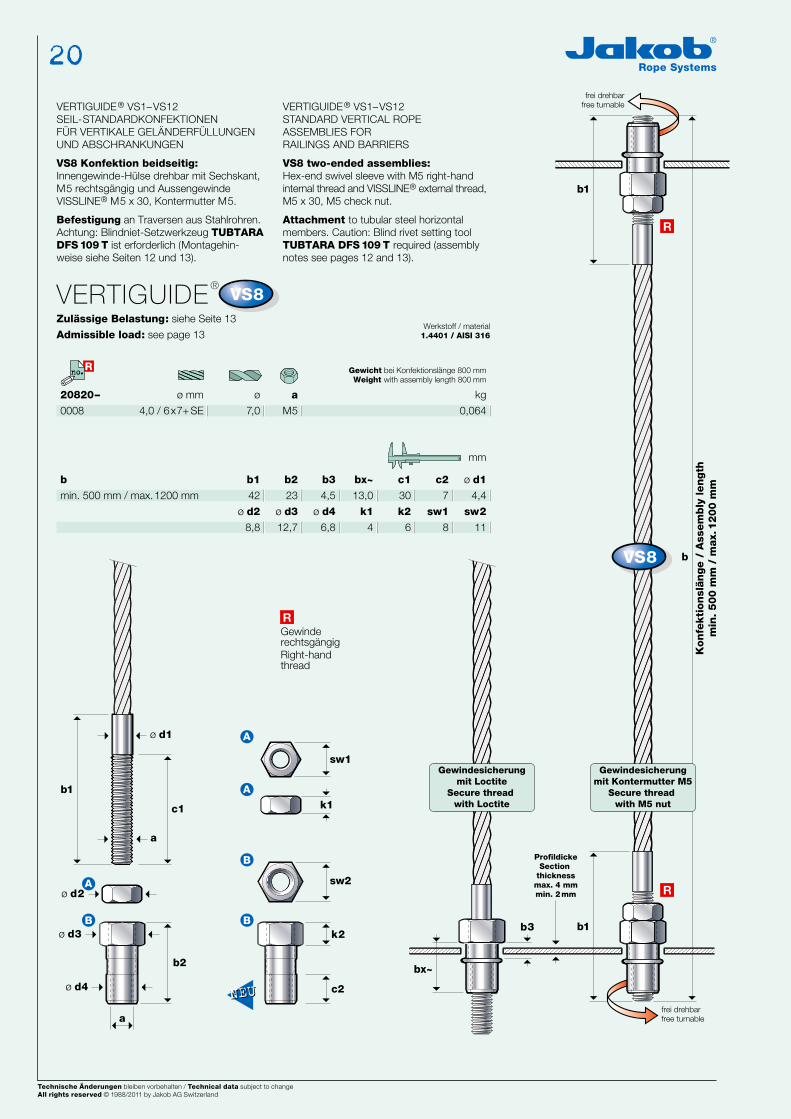
VS8 Konfektion beidseitig: Innengewinde-Hülse drehbar mit Sechskant, M5 rechtsgängig und Aussengewinde VISSLINE® M5 x 30, Kontermutter M5.
Befestigung an Traversen aus Stahlrohren. Achtung: Blindniet-Setzwerkzeug TUBTARA DFS 109 T ist erforderlich (Montagehin-weise siehe Seiten 12 und 13).
VERTIGUIDE® VS1–VS12STANDARD VERTICAL ROPE ASSEMBLIES FORRAILINGS AND BARRIERS
VS8 two-ended assemblies:Hex-end swivel sleeve with M5 right-hand internal thread and VISSLINE® external thread, M5 x 30, M5 check nut.
Attachment to tubular steel horizontal members. Caution: Blind rivet setting tool TUBTARA DFS 109 T required (assembly notes see pages 12 and 13).
ø d1
4,4
c2
7
b2
23
b3
4,5
bx~
13,0
c1
30
b1
42
b
min. 500 mm / max. 1200 mm
sw1
8
k2
6
k1
4
ø d4
6,8
ø d3
12,7
ø d2
8,8
sw2
11
mm
ø
7,0
Gewinde rechtsgängig Right-hand thread
Gewicht bei Konfektionslänge 800 mmWeight with assembly length 800 mm
kg
0,064
ø mm
4,0 / 6x7+ SE
20820–
0009
0009–01 (mit zwei Formanschlüssen / with two post fittings)
VERTIGUIDE®
Bruchkraft: 90% der Seil-Mindestbruchkraft
Breaking strength: 90% of min. rope breaking loadWerkstoff / material
1.4401 / AISI 316
a
M5
VERTIGUIDE® VS1–VS12SEIL-STANDARDKONFEKTIONEN FÜR VERTIKALE GELÄNDERFÜLLUNGEN UND ABSCHRANKUNGEN
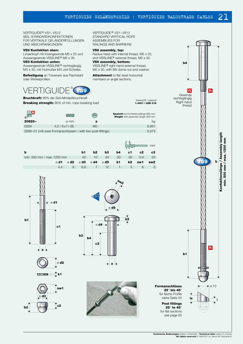
VS9 Konfektion oben: Linsenkopf mit Innengewinde M5 x 20 und Aussengewinde VISSLINE® M5 x 30.VS9 Konfektion unten: Aussengewinde VISSLINE® rechtsgängig M5 x 30, mit Hutmutter M5 und Scheibe.
Befestigung an Traversen aus Flachstahl oder Winkelprofilen.
VERTIGUIDE® VS1–VS12STANDARD VERTICAL ROPE ASSEMBLIES FORRAILINGS AND BARRIERS
VS9 assembly, top:Radius head with internal thread, M5 x 20, and VISSLINE® external thread, M5 x 30.VS9 assembly, bottom:VISSLINE® right-hand external thread, M5 x 30, with M5 dome nut and washer.
Attachment to flat steel horizontal members or angle sections.
b2
10
b3
34
b4
30
c1
30
c2
5.9
c3
20
b1
42
b
min. 500 mm / max. 1200 mm
k1
1
k2
3
ø d5
12
ø d4
7
ø d3
8,8
ø d2
9
ø d1
4,4
sw2
3
sw1
8
mm
Gewinderechtsgängig
Right-handthread
Gewicht bei Konfektionslänge 800 mmWeight with assembly length 800 mm
kg
0,061
0,073
Formanschlüsse25° bis 45°
für flache Profilesiehe Seite 55
Post fittings25° to 45°
for flat sectionssee page 55
Kon
fekti
on
slän
ge /
Ass
em
bly
len
gth
min
. 5
00
mm
/ m
ax.
12
00
mm
Gewindesicherungmit Kontermutter M5
Secure thread with M5 nut
Gewindesicherungmit Loctite
Secure thread with Loctite
ProfildickeSection
thicknessmax. 4 mmmin. 2 mm
Kon
fekti
on
slän
ge /
Ass
em
bly
len
gth
min
. 5
00
mm
/ m
ax.
12
00
mm
frei drehbarfree turnable
frei drehbarfree turnable
Technische Änderungen bleiben vorbehalten / Technical data subject to changeAll rights reserved © 1988/2002 by Jakob AG Switzerland
Technische Änderungen bleiben vorbehalten / Technical data subject to changeAll rights reserved © 1988/2002 by Jakob AG Switzerland Technische Änderungen bleiben vorbehalten / Technical data subject to changeAll rights reserved © 1988/2011 by Jakob AG Switzerland
20
NEWS 2002 6362
b1
b1
b1
c1
a
b
a
ø d1
ø d2
ø d3
ø d4
sw1
sw2
k1
b2bx~
k2
c2
A
B
A
A
B
B
b3
R
R
b4
b1
b
b1
c1
a
ø d1
ø d2
k1
c2b2
sw1
ø d3
R
R
k2
ø d4
b4b3
c3
a
sw2
ø d5
3lx
ø 10
R Rno.no.
VS8
VS8
NEUNEU
R
VS9
VS9
R
NEUNEU
ø mm
4,0 / 6x7+ SE
20820–
0008
VERTIGUIDE®
Zulässige Belastung: siehe Seite 13
Admissible load: see page 13Werkstoff / material
1.4401 / AISI 316
a
M5
VERTIGUIDE® VS1–VS12SEIL-STANDARDKONFEKTIONEN FÜR VERTIKALE GELÄNDERFÜLLUNGEN UND ABSCHRANKUNGEN
VS8 Konfektion beidseitig: Innengewinde-Hülse drehbar mit Sechskant, M5 rechtsgängig und Aussengewinde VISSLINE® M5 x 30, Kontermutter M5.
Befestigung an Traversen aus Stahlrohren. Achtung: Blindniet-Setzwerkzeug TUBTARA DFS 109 T ist erforderlich (Montagehin-weise siehe Seiten 12 und 13).
VERTIGUIDE® VS1–VS12STANDARD VERTICAL ROPE ASSEMBLIES FORRAILINGS AND BARRIERS
VS8 two-ended assemblies:Hex-end swivel sleeve with M5 right-hand internal thread and VISSLINE® external thread, M5 x 30, M5 check nut.
Attachment to tubular steel horizontal members. Caution: Blind rivet setting tool TUBTARA DFS 109 T required (assembly notes see pages 12 and 13).
ø d1
4,4
c2
7
b2
23
b3
4,5
bx~
13,0
c1
30
b1
42
b
min. 500 mm / max. 1200 mm
sw1
8
k2
6
k1
4
ø d4
6,8
ø d3
12,7
ø d2
8,8
sw2
11
mm
ø
7,0
Gewinde rechtsgängig Right-hand thread
Gewicht bei Konfektionslänge 800 mmWeight with assembly length 800 mm
kg
0,064
ø mm
4,0 / 6x7+ SE
20820–
0009
0009–01 (mit zwei Formanschlüssen / with two post fittings)
VERTIGUIDE®
Bruchkraft: 90% der Seil-Mindestbruchkraft
Breaking strength: 90% of min. rope breaking loadWerkstoff / material
1.4401 / AISI 316
a
M5
VERTIGUIDE® VS1–VS12SEIL-STANDARDKONFEKTIONEN FÜR VERTIKALE GELÄNDERFÜLLUNGEN UND ABSCHRANKUNGEN
VS9 Konfektion oben: Linsenkopf mit Innengewinde M5 x 20 und Aussengewinde VISSLINE® M5 x 30.VS9 Konfektion unten: Aussengewinde VISSLINE® rechtsgängig M5 x 30, mit Hutmutter M5 und Scheibe.
Befestigung an Traversen aus Flachstahl oder Winkelprofilen.
VERTIGUIDE® VS1–VS12STANDARD VERTICAL ROPE ASSEMBLIES FORRAILINGS AND BARRIERS
VS9 assembly, top:Radius head with internal thread, M5 x 20, and VISSLINE® external thread, M5 x 30.VS9 assembly, bottom:VISSLINE® right-hand external thread, M5 x 30, with M5 dome nut and washer.
Attachment to flat steel horizontal members or angle sections.
b2
10
b3
34
b4
30
c1
30
c2
5.9
c3
20
b1
42
b
min. 500 mm / max. 1200 mm
k1
1
k2
3
ø d5
12
ø d4
7
ø d3
8,8
ø d2
9
ø d1
4,4
sw2
3
sw1
8
mm
Gewinderechtsgängig
Right-handthread
Gewicht bei Konfektionslänge 800 mmWeight with assembly length 800 mm
kg
0,061
0,073
Formanschlüsse25° bis 45°
für flache Profilesiehe Seite 55
Post fittings25° to 45°
for flat sectionssee page 55
Kon
fekti
on
slän
ge /
Ass
em
bly
len
gth
min
. 5
00
mm
/ m
ax.
12
00
mm
Gewindesicherungmit Kontermutter M5
Secure thread with M5 nut
Gewindesicherungmit Loctite
Secure thread with Loctite
ProfildickeSection
thicknessmax. 4 mmmin. 2 mm
Kon
fekti
on
slän
ge /
Ass
em
bly
len
gth
min
. 5
00
mm
/ m
ax.
12
00
mm
frei drehbarfree turnable
frei drehbarfree turnable
Technische Änderungen bleiben vorbehalten / Technical data subject to changeAll rights reserved © 1988/2002 by Jakob AG Switzerland
Technische Änderungen bleiben vorbehalten / Technical data subject to changeAll rights reserved © 1988/2002 by Jakob AG Switzerland
Technische Änderungen bleiben vorbehalten / Technical data subject to changeAll rights reserved © 1988/2011 by Jakob AG Switzerland
21 VERTIGUIDE GELÄNDERSEILE | VERTIGUIDE BALUSTRADE CABLES
NEWS 2002 6564
b4
b1
b
b1
c1
a
ø d1
ø d2
k1
c2b2
sw1
ø d3
R
R
k3
k2ø d4
b4b3
c3
a
sw2
ø d5
3lx
ø10
f
f
b1
c1
g
k
a
b
ø d1
R
L
f
e
ø d2h
b2
c2
a
R Rno.no.
VS10
VS10
R
NEUNEU
VS11
VS11
L
R
ø mm
4,0 / 6x7+ SE
20820–
0010
0010–01 (mit zwei Formanschlüssen / with two post fittings)
VERTIGUIDE®
Bruchkraft: 90% der Seil-Mindestbruchkraft
Breaking strength: 90% of min. rope breaking loadWerkstoff / material
1.4401 / AISI 316
a
M5
VERTIGUIDE® VS1–VS12SEIL-STANDARDKONFEKTIONEN FÜR VERTIKALE GELÄNDERFÜLLUNGEN UND ABSCHRANKUNGEN
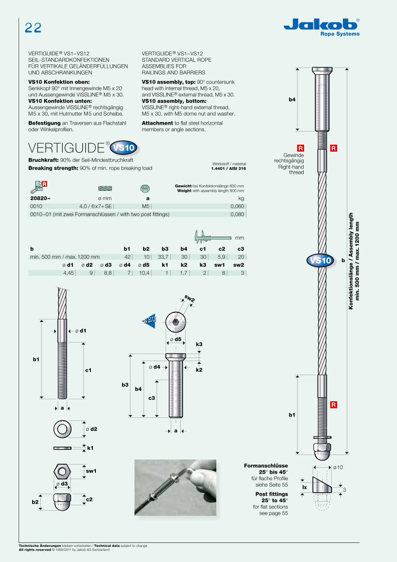
VS10 Konfektion oben: Senkkopf 90° mit Innengewinde M5 x 20 und Aussengewinde VISSLINE® M5 x 30.VS10 Konfektion unten: Aussengewinde VISSLINE® rechtsgängig M5 x 30, mit Hutmutter M5 und Scheibe.
Befestigung an Traversen aus Flachstahl oder Winkelprofilen.
VERTIGUIDE® VS1–VS12STANDARD VERTICAL ROPE ASSEMBLIES FORRAILINGS AND BARRIERS
VS10 assembly, top: 90° countersunk head with internal thread, M5 x 20, and VISSLINE® external thread, M5 x 30.VS10 assembly, bottom:VISSLINE® right-hand external thread, M5 x 30, with M5 dome nut and washer.
Attachment to flat steel horizontal members or angle sections.
b2
10
b3
33,7
b4
30
c1
30
c2
5,9
c3
20
b1
42
b
min. 500 mm / max. 1200 mm
k1
1
k2
1,7
k3
2
ø d5
10,4
ø d4
7
ø d3
8,8
ø d2
9
ø d1
4,45
sw2
3
sw1
8
mm
Gewinderechtsgängig
Right-handthread
Gewicht bei Konfektionslänge 800 mmWeight with assembly length 800 mm
kg
0,060
0,080
Formanschlüsse25° bis 45°
für flache Profilesiehe Seite 55
Post fittings25° to 45°
for flat sectionssee page 55
ø mm
4,0 / 6x7+ SE
20820–
0011
VERTIGUIDE®
Bruchkraft: 90% der Seil-Mindestbruchkraft
Breaking strength: 90% of min. rope breaking loadWerkstoff / material
1.4401 / AISI 316
a
M6
VERTIGUIDE® VS1–VS12SEIL-STANDARDKONFEKTIONEN FÜR VERTIKALE GELÄNDERFÜLLUNGEN UND ABSCHRANKUNGEN
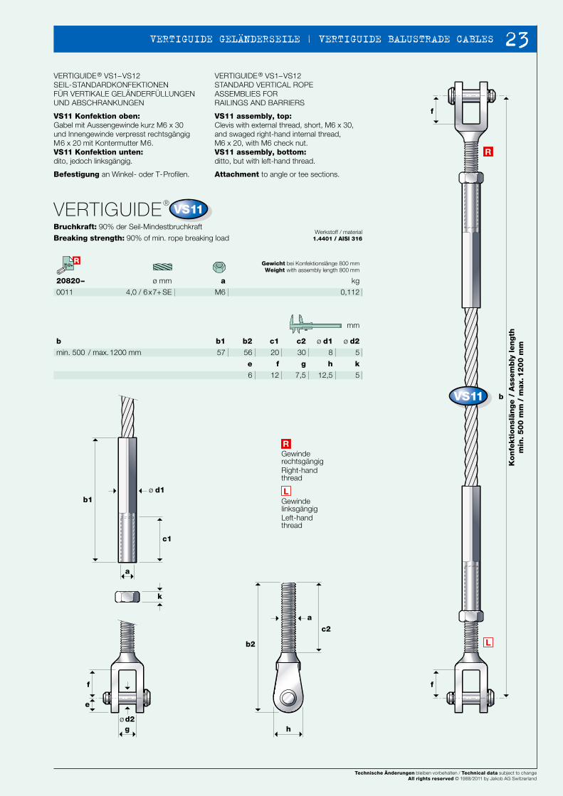
VS11 Konfektion oben: Gabel mit Aussengewinde kurz M6 x 30 und Innengewinde verpresst rechtsgängig M6 x 20 mit Kontermutter M6.VS11 Konfektion unten: dito, jedoch linksgängig.
Befestigung an Winkel- oder T-Profilen.
VERTIGUIDE® VS1–VS12STANDARD VERTICAL ROPE ASSEMBLIES FORRAILINGS AND BARRIERS
VS11 assembly, top:Clevis with external thread, short, M6 x 30, and swaged right-hand internal thread, M6 x 20, with M6 check nut.VS11 assembly, bottom:ditto, but with left-hand thread.
Attachment to angle or tee sections.
ø d2
5
ø d1
8
b2
56
c1
20
c2
30
b1
57
b
min. 500 / max. 1200 mm
mm
Gewinde linksgängig Left-hand thread
Gewinde rechtsgängig Right-hand thread
g
7,5
f
12
e
6
h
12,5
k
5
Gewicht bei Konfektionslänge 800 mmWeight with assembly length 800 mm
kg
0,112
Kon
fekti
on
slän
ge /
Ass
em
bly
len
gth
min
. 5
00
mm
/ m
ax.
12
00
mm
Kon
fekti
on
slän
ge /
Ass
em
bly
len
gth
min
. 5
00
mm
/ m
ax.
12
00
mm
Technische Änderungen bleiben vorbehalten / Technical data subject to changeAll rights reserved © 1988/2002 by Jakob AG Switzerland
Technische Änderungen bleiben vorbehalten / Technical data subject to changeAll rights reserved © 1988/2002 by Jakob AG Switzerland Technische Änderungen bleiben vorbehalten / Technical data subject to changeAll rights reserved © 1988/2011 by Jakob AG Switzerland
22
NEWS 2002 6564
b4
b1
b
b1
c1
a
ø d1
ø d2
k1
c2b2
sw1
ø d3
R
R
k3
k2ø d4
b4b3
c3
a
sw2
ø d5
3lx
ø10
f
f
b1
c1
g
k
a
b
ø d1
R
L
f
e
ø d2h
b2
c2
a
R Rno.no.
VS10
VS10
R
NEUNEU
VS11
VS11
L
R
ø mm
4,0 / 6x7+ SE
20820–
0010
0010–01 (mit zwei Formanschlüssen / with two post fittings)
VERTIGUIDE®
Bruchkraft: 90% der Seil-Mindestbruchkraft
Breaking strength: 90% of min. rope breaking loadWerkstoff / material
1.4401 / AISI 316
a
M5
VERTIGUIDE® VS1–VS12SEIL-STANDARDKONFEKTIONEN FÜR VERTIKALE GELÄNDERFÜLLUNGEN UND ABSCHRANKUNGEN
VS10 Konfektion oben: Senkkopf 90° mit Innengewinde M5 x 20 und Aussengewinde VISSLINE® M5 x 30.VS10 Konfektion unten: Aussengewinde VISSLINE® rechtsgängig M5 x 30, mit Hutmutter M5 und Scheibe.
Befestigung an Traversen aus Flachstahl oder Winkelprofilen.
VERTIGUIDE® VS1–VS12STANDARD VERTICAL ROPE ASSEMBLIES FORRAILINGS AND BARRIERS
VS10 assembly, top: 90° countersunk head with internal thread, M5 x 20, and VISSLINE® external thread, M5 x 30.VS10 assembly, bottom:VISSLINE® right-hand external thread, M5 x 30, with M5 dome nut and washer.
Attachment to flat steel horizontal members or angle sections.
b2
10
b3
33,7
b4
30
c1
30
c2
5,9
c3
20
b1
42
b
min. 500 mm / max. 1200 mm
k1
1
k2
1,7
k3
2
ø d5
10,4
ø d4
7
ø d3
8,8
ø d2
9
ø d1
4,45
sw2
3
sw1
8
mm
Gewinderechtsgängig
Right-handthread
Gewicht bei Konfektionslänge 800 mmWeight with assembly length 800 mm
kg
0,060
0,080
Formanschlüsse25° bis 45°
für flache Profilesiehe Seite 55
Post fittings25° to 45°
for flat sectionssee page 55
ø mm
4,0 / 6x7+ SE
20820–
0011
VERTIGUIDE®
Bruchkraft: 90% der Seil-Mindestbruchkraft
Breaking strength: 90% of min. rope breaking loadWerkstoff / material
1.4401 / AISI 316
a
M6
VERTIGUIDE® VS1–VS12SEIL-STANDARDKONFEKTIONEN FÜR VERTIKALE GELÄNDERFÜLLUNGEN UND ABSCHRANKUNGEN
VS11 Konfektion oben: Gabel mit Aussengewinde kurz M6 x 30 und Innengewinde verpresst rechtsgängig M6 x 20 mit Kontermutter M6.VS11 Konfektion unten: dito, jedoch linksgängig.
Befestigung an Winkel- oder T-Profilen.
VERTIGUIDE® VS1–VS12STANDARD VERTICAL ROPE ASSEMBLIES FORRAILINGS AND BARRIERS
VS11 assembly, top:Clevis with external thread, short, M6 x 30, and swaged right-hand internal thread, M6 x 20, with M6 check nut.VS11 assembly, bottom:ditto, but with left-hand thread.
Attachment to angle or tee sections.
ø d2
5
ø d1
8
b2
56
c1
20
c2
30
b1
57
b
min. 500 / max. 1200 mm
mm
Gewinde linksgängig Left-hand thread
Gewinde rechtsgängig Right-hand thread
g
7,5
f
12
e
6
h
12,5
k
5
Gewicht bei Konfektionslänge 800 mmWeight with assembly length 800 mm
kg
0,112
Kon
fekti
on
slän
ge /
Ass
em
bly
len
gth
min
. 5
00
mm
/ m
ax.
12
00
mm
Kon
fekti
on
slän
ge /
Ass
em
bly
len
gth
min
. 5
00
mm
/ m
ax.
12
00
mm
Technische Änderungen bleiben vorbehalten / Technical data subject to changeAll rights reserved © 1988/2002 by Jakob AG Switzerland
Technische Änderungen bleiben vorbehalten / Technical data subject to changeAll rights reserved © 1988/2002 by Jakob AG Switzerland
Technische Änderungen bleiben vorbehalten / Technical data subject to changeAll rights reserved © 1988/2011 by Jakob AG Switzerland
23 VERTIGUIDE GELÄNDERSEILE | VERTIGUIDE BALUSTRADE CABLES
NEWS 2002 6766
L
f
e
b2
c2
f
f
b
b1
c1
R
ø d1
a
a
k
ø d2g
ø d3
Rno.
VS12
VS12
L
R
VS12
ø mm
4,0 / 6x7+ SE
20820–
0012
VERTIGUIDE®
Bruchkraft: 90% der Seil-Mindestbruchkraft
Breaking strength: 90% of min. rope breaking loadWerkstoff / material
1.4401 / AISI 316
a
M5
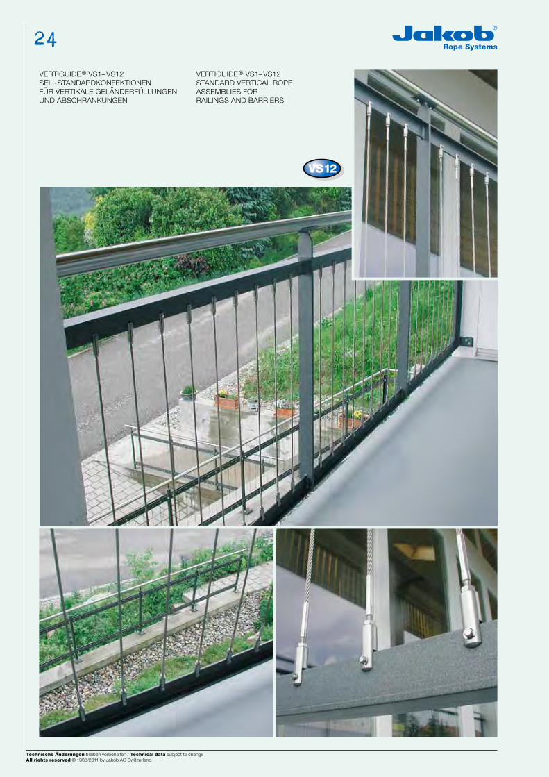
VERTIGUIDE® VS1–VS12SEIL-STANDARDKONFEKTIONEN FÜR VERTIKALE GELÄNDERFÜLLUNGEN UND ABSCHRANKUNGEN
VS12 Konfektion oben: Gabel mit Innengewinde M5 x 15 und Aussengewinde VISSLINE® rechtsgängig M5 x 20 mit Kontermutter M5.VS12 Konfektion unten: dito, jedoch linksgängig.
Befestigung an Winkel- und T-Profilen oder Flachprofilen.
VERTIGUIDE® VS1–VS12STANDARD VERTICAL ROPE ASSEMBLIES FORRAILINGS AND BARRIERS
VS12 assembly, top:Clevis with internal thread, M5 x 15, and VISSLINE® right-hand external thread, M5 x 20, with M5 check nut.VS12 assembly, bottom:ditto, but with left-hand thread.
Attachment to angle and tee sections or flat sections.
ø d2
5
ø d3
12
ø d1
4,4
b2
36
c1
20
c2
15
b1
32
b
min. 500 / max. 1200 mm
mm
Gewinde linksgängig Left-hand thread
Gewinde rechtsgängig Right-hand thread
g
5
f
9
e
8
k
4
Gewicht bei Konfektionslänge 800 mmWeight with assembly length 800 mm
kg
0,093
VERTIGUIDE® VS1–VS12SEIL-STANDARDKONFEKTIONEN FÜR VERTIKALE GELÄNDERFÜLLUNGEN UND ABSCHRANKUNGEN
VERTIGUIDE® VS1–VS12STANDARD VERTICAL ROPE ASSEMBLIES FORRAILINGS AND BARRIERS
Kon
fekti
on
slän
ge /
Ass
em
bly
len
gth
min
. 5
00
mm
/ m
ax.
12
00
mm
Technische Änderungen bleiben vorbehalten / Technical data subject to changeAll rights reserved © 1988/2002 by Jakob AG Switzerland
Technische Änderungen bleiben vorbehalten / Technical data subject to changeAll rights reserved © 1988/2002 by Jakob AG Switzerland Technische Änderungen bleiben vorbehalten / Technical data subject to changeAll rights reserved © 1988/2011 by Jakob AG Switzerland
24
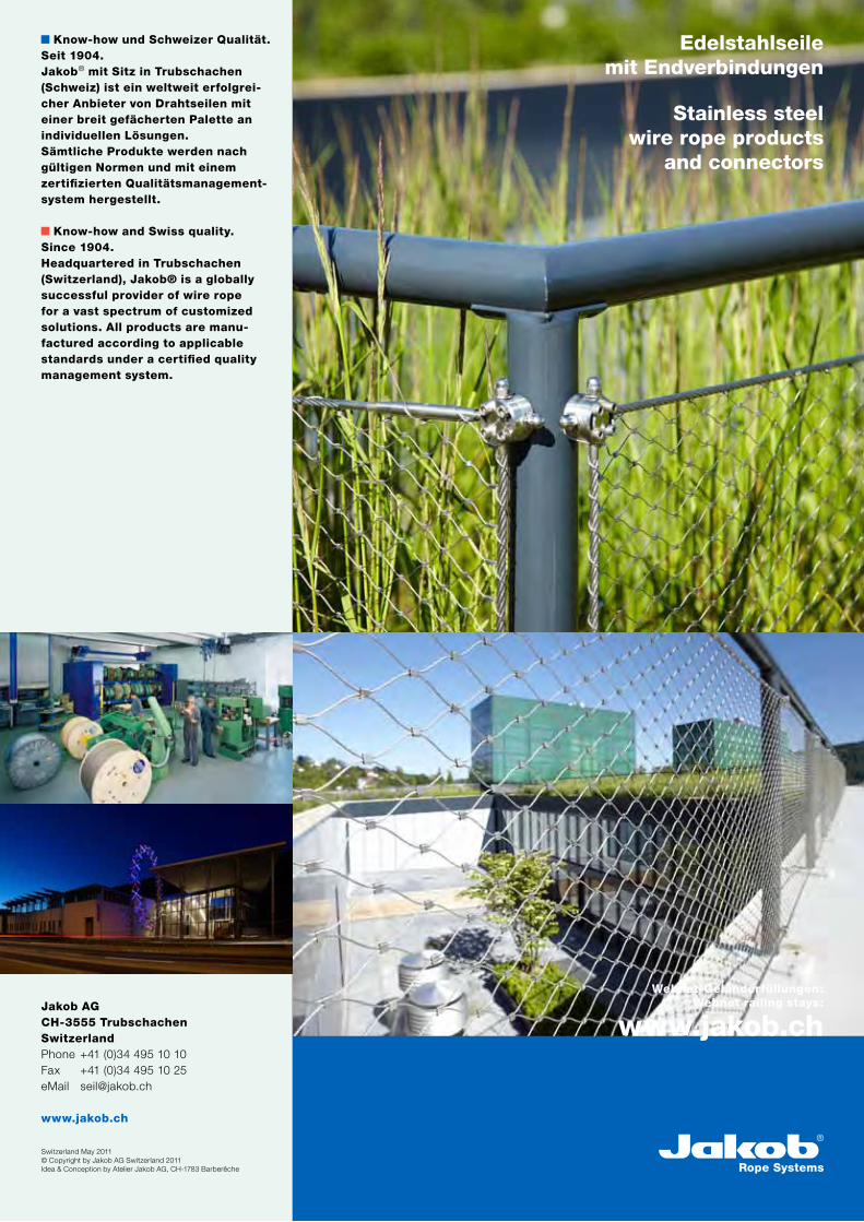
Know-how und Schweizer Qualität. Seit 1904.Jakob® mit Sitz in Trubschachen (Schweiz) ist ein weltweit erfolgrei-cher Anbieter von Drahtseilen mit einer breit gefächerten Palette an individuellen Lösungen. Sämtliche Produkte werden nach gültigen Normen und mit einem zertifizierten Qualitätsmanagement-system hergestellt.
Know-how and Swiss quality.Since 1904.Headquartered in Trubschachen (Switzerland), Jakob® is a globally successful provider of wire rope for a vast spectrum of customized solutions. All products are manu-factured according to applicable standards under a certified quality management system.
Jakob AGCH-3555 TrubschachenSwitzerlandPhone +41 (0)34 495 10 10Fax +41 (0)34 495 10 25eMail [email protected]
www.jakob.ch
Switzerland May 2011 © Copyright by Jakob AG Switzerland 2011Idea & Conception by Atelier Jakob AG, CH-1783 Barberêche
Stainless steel wire rope products
and connectors
Edelstahlseile mit Endverbindungen
Webnet-Geländerfüllungen:Webnet railing stays:
www.jakob.ch