Embed Size (px)
Citation preview
Artikel Nr. 771074115 Rev. 02 01/2010
de VOGEL-Mehrstufenpumpen Baureihe MPB, MPV
Einbau-, Betriebs- und Wartungsanleitung
Originalbetriebsanleitung
fr VOGEL-Pompes multicellulaires Série MPB, MPV
Instructions de montage, de service et de maintenance
Traduction de la notice d’exploitation originale
en VOGEL-Multistage Pumps Model MPB, MPV
Installation, Operation and Maintenance Instructions
Translation of the Original Operation Manual
de Für künftige Verwendung aufbewahren ! Diese Betriebsanleitung vor dem Transport, dem Einbau, der Inbetriebnahme usw. genau beachten!
fr Conserver soigneusement ces instructions pour consultations ultérieures ! Lire attentivement ces instructions de service avant le transport, le montage, la mise en service etc. !
en Keep for further use ! Pay attention to this operating instruction before the delivery, installation, start-up a.s.o.!
EC Declaration of Conformity (valid only for Xylem Water Solutions Austria GmbH aggregate supplied in its entirety) (according to EC Directive on Machinery 2006/42/EC, Annex II A)
The manufacturer, Xylem Water Solutions Austria GmbH Ernst Vogel-Strasse 2 2000 Stockerau
Austria of the pumps from the standard product line hereby declares:
MPB40.2, MPB40.3, MPB65.1, MPB65.2, MPB100.1, MPB100.2, MPV40.2, MPV40.3, MPV65.1, MPV65.2, MPV100.1, MPV100.2, MPV125.1, MPV125.2
� The supplied aggregates meet the relevant regulations of the EC Directive on Machinery, 2006/42/EC � The three-phase electric motor supplied at the same time meets the relevant regulations of Directive
2004/108/EC. � Special technical documentation has been prepared, in accordance with Annex VII A. � If necessary, we can submit the above-listed special technical documentation, in electronic form on a data
storage medium, to the relevant authorities. � The above-listed special documentation can be requested at the following address:
Dipl. Ing. Gerhard Fasching Abtlg. Research & Development Xylem Water Solutions Austria GmbH
Ernst Vogel-Strasse 2 2000 Stockerau Austria
� Among others, the following harmonised standards have been applied:
EN 809 :1998+A1:2009+AC:2010(D) EN 953 :1997+A1:2009(D) EN ISO 12100 :2010(D) EN 60204-1 :2006/A1:2009 D
� A change to an aggregate which was not approved by us invalidates this declaration. This also applies in
the case that the aggregate is installed in equipment that does not have the declaration of conformity in accordance with the Directive on Machinery, 2006/42/EC.
Stockerau, 09.01.2012 ................................................................................................
Dir. Peter Steinbach Production manager
Installation, Operating and Maintenance Instruction Model MPB, MPV
MPB 100-english page 69 Revision 02 Article No 771074115 Issue 01/2010
TABLE of CONTENTS
Pump Name Plate ................................................... 70
1. General................................................................. 71
1.1 Guarantee ....................................................... 71
2. Safety Regulations ............................................. 71
2.1 Marking of References in the Operating Instructions ............................................................ 71 2.2 Dangers of non-observance of the Safety Instructions ............................................................ 72 2.3 Safety Instructions for the Operator / Worker . 72 2.4 Safety Instructions for Maintenance, Inspections and Mounting Work ............................................... 72 2.5 Unauthorized Alteration and Spare Parts Production ............................................................. 72 2.6 Undue Operation ............................................. 72 2.7 Explosion Protection........................................ 72 2.8 Use acc. to Regulations .................................. 74
3. Description .......................................................... 75
3.1 Models ............................................................. 75 3.2 Shaft Sealing ................................................... 75 3.3 Bearings .......................................................... 75 3.4 Approximate Value for Sound Pressure Level 75 3.5 Permitted Nozzle Loads and Torques at the Pump Nozzles ... ................................................... 75 3.6 Permitted Pressures and Temperatures ......... 77
4. Transport, Handling, Storage ............................ 77
4.1 Transport, Handling ......................................... 77 4.2 Storage / Preservation..................................... 78
5. Mounting / Installation ....................................... 78
5.1 Mounting the unit / Foundation ........................ 78 5.2 Connection of Pipings to the Pump ................. 78 5.3 Coupling .......................................................... 79 5.4 Drive ................................................................ 79 5.5 Electric Connection ......................................... 79 5.6 Final Control .................................................... 80
6. Start-up, Operation, Shut down ........................ 80
6.1 Initial start-up ................................................... 80 6.2 Switch on drive ................................................ 80
6.3 Restarting ........................................................ 80 6.4 Limits of Operation .......................................... 81 6.5 Lubrication of Bearings .................................... 81 6.6 Monitoring ........................................................ 81 6.7 Shutting down .................................................. 81 6.8 Storage / longer periods of non-operation ....... 82
7. Servicing, Maintenance ...................................... 82
7.1 General remarks .............................................. 82 7.2 Mechanical seals ............................................. 82 7.3 Stuffing boxes .................................................. 82 7.4 Lubrication and Change of Lubricant ............... 83 7.5 Coupling ........................................................... 83 7.6 Cleaning of pump ............................................ 83
8. Dismantling and repair of pump ........................ 83
8.1 General remarks .............................................. 83 8.2 General ............................................................ 84 8.3 Tools and Equipment ....................................... 84 8.4 Dismantling the Pump ..................................... 84 8.5 Replacing Roller Bearings ............................... 84 8.6 Replacing the Slide Bearing ............................ 85 8.7 Replacement of the shaft sleeve with a packing gland / Replacement of the mechanical seal ......... 85 8.8 Dismantling ...................................................... 89 8.9 Repairs ............................................................ 89
9. Reassembly ......................................................... 91
9.1 Preparation ...................................................... 91 9.2 Model MPB ...................................................... 92 9.3 Model MPV ...................................................... 92
10. Spare Parts, Spare Pumps ............................... 93
10.1 Spare Parts .................................................... 93 10.2 Stand-by pumps ............................................. 93
11. Faults - Causes and Solutions ......................... 93
Weights of the MPB Design................................... 95 Weights of the MPV Design................................... 96 Tightening Torques ................................................ 96
12. Motor Operating Instructions .......................... 97
Installation, Operating and Maintenance Instruction Model MPB, MPV
MPB 100-english page 70 Revision 02 Article No 771074115 Issue 01/2010
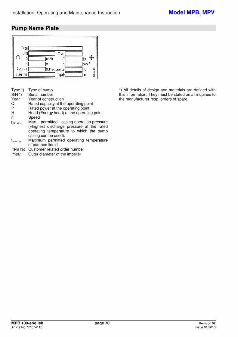
Pump Name Plate
Type *) Type of pump S/N *) Serial number Year Year of construction Q Rated capacity at the operating point P Rated power at the operating point H Head (Energy head) at the operating point n Speed pall w C Max. permitted casing-operation-pressure
(=highest discharge pressure at the rated operating temperature to which the pump casing can be used).
tmax op Maximum permitted operating temperature of pumped liquid
Item No Customer related order number Imp∅ Outer diameter of the impeller
*) All details of design and materials are defined with this information. They must be stated on all inquiries to the manufacturer resp. orders of spare.
Installation, Operating and Maintenance Instruction Model MPB, MPV
MPB 100-english page 71 Revision 02 Article No 771074115 Issue 01/2010
1. General This product corresponds with the requirements of the Machine directive 2006/42/EG.
The staff employed on installation, operation, inspection and maintenance must be able to prove that they know about the relevant accident prevention regulations and that they are suitably qualified for this work. If the staff does not have the relevant knowledge, they should be provided with suitable instruction.
The operation safety of the delivered pump resp. unit (= pump with motor) can only be guaranteed on designated use according to the attached data sheet and / or order confirmation resp. chapter 6 "Start-up, Operation, Shut down". The operator is responsible for following the instructions and complying with the safety requirements given in these Operating Instructions. Smooth operation of the pump or pump unit can only be achieved if installation and maintenance are carried out carefully in accordance with the rules generally applied in the field of engineering and electrical engineering. If not all the information can be found in these Operating Instructions, please contact us. The manufacturer takes no responsibility for the pump or pump unit if the Operating Instructions are not followed. These Operating Instructions should be kept in a safe place for future use. If this pump or pump unit is handed on to any third party, it is essential that these Operating Instructions and the operating conditions and working limits given in the Confirmation of Order are also passed on in full. These Operating Instructions do not take into account all design details and variants nor all the possible
chance occurrences and events which might happen during installation, operation and maintenance. We retain all copyright in these Operating Instructions; they are intended only for personal use by the owner of the pump or the pump unit. The Operating Instructions contain technical instructions and drawings which may not, as a whole or in part, be reproduced, distributed or used in any unauthorised way for competitive purposes or passed on to others.
1.1 Guarantee The guarantee is given in accordance with our Conditions of Delivery and/or the confirmation of order. Repair work during the guarantee period may only be carried out by us, or subject to our written approval. Otherwise the guarantee ceases to apply. Longer-term guarantees basically only cover correct handling and use of the specified material. The guarantee shall not cover natural wear and tear and all parts subject to wear, such as impellers, shaft sealings, shafts, shaft sleeves, bearings, wear rings etc. or damage caused by transport or improper handling. In order for the guarantee to apply, it is essential that the pump or pump unit is used in accordance with the operating conditions given on the name plate, confirmation of order and in the data sheet. This applies particularly for the endurance of the materials and smooth running of the pump and shaft sealing. If one or more aspects of the actual operating conditions are different, we should be asked to confirm in writing that the pump is suitable.
2. Safety Regulations These Operating Instructions contain important instructions which must be followed when the pump is assembled and commissioned and during operating and maintenance. For this reason, these Operating Instructions must be read by the skilled staff responsible and/or by the operator of the plant before it is installed and commissioned, and they must be left permanently available at the place where the pump or pump unit is in use. These Operating Instructions do not refer to the General Regulations on Accident Prevention or local safety and/or operating regulations. The operator is responsible for complying with these (if necessary by calling in additional installation staff). Equally, instructions and safety devices regarding handling and disposal of the pumped media and/or auxiliary media for flushing, lubrication a.s.o., especially if they are explosive, toxical, hot a.s.o., are not part of this operating instruction.
For the competent and prescribed handling only the operator is responsible.
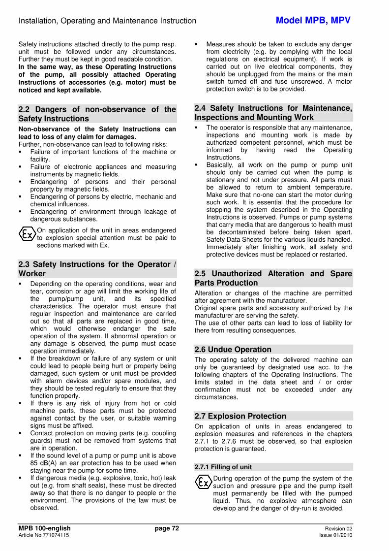
2.1 Marking of References in the Operating Instructions The safety regulations contained in these Operating Instructions are specially marked with safety signs acc. to nach DIN 4844:
Safety reference! Non-observance can impair the pump and its function.
EC-Ex Marking Products intended for use in explosive atmospheres must be marked.
General Symbol for Danger! Persons can be endangered.
Warning of electric voltage!
Installation, Operating and Maintenance Instruction Model MPB, MPV
MPB 100-english page 72 Revision 02 Article No 771074115 Issue 01/2010
Safety instructions attached directly to the pump resp. unit must be followed under any circumstances. Further they must be kept in good readable condition. In the same way, as these Operating Instructions of the pump, all possibly attached Operating Instructions of accessories (e.g. motor) must be noticed and kept available.
2.2 Dangers of non-observance of the Safety Instructions Non-observance of the Safety Instructions can lead to loss of any claim for damages. Further, non-observance can lead to following risks: � Failure of important functions of the machine or
facility. � Failure of electronic appliances and measuring
instruments by magnetic fields. � Endangering of persons and their personal
property by magnetic fields. � Endangering of persons by electric, mechanic and
chemical influences. � Endangering of environment through leakage of
dangerous substances.
On application of the unit in areas endangered to explosion special attention must be paid to sections marked with Ex.
2.3 Safety Instructions for the Operator / Worker � Depending on the operating conditions, wear and
tear, corrosion or age will limit the working life of the pump/pump unit, and its specified characteristics. The operator must ensure that regular inspection and maintenance are carried out so that all parts are replaced in good time, which would otherwise endanger the safe operation of the system. If abnormal operation or any damage is observed, the pump must cease operation immediately.
� If the breakdown or failure of any system or unit could lead to people being hurt or property being damaged, such system or unit must be provided with alarm devices and/or spare modules, and they should be tested regularly to ensure that they function properly.
� If there is any risk of injury from hot or cold machine parts, these parts must be protected against contact by the user, or suitable warning signs must be affixed.
� Contact protection on moving parts (e.g. coupling guards) must not be removed from systems that are in operation.
� If the sound level of a pump or pump unit is above 85 dB(A) an ear protection has to be used when staying near the pump for some time.
� If dangerous media (e.g. explosive, toxic, hot) leak out (e.g. from shaft seals), these must be directed away so that there is no danger to people or the environment. The provisions of the law must be observed.
� Measures should be taken to exclude any danger from electricity (e.g. by complying with the local regulations on electrical equipment). If work is carried out on live electrical components, they should be unplugged from the mains or the main switch turned off and fuse unscrewed. A motor protection switch is to be provided.
2.4 Safety Instructions for Maintenance, Inspections and Mounting Work � The operator is responsible that any maintenance,
inspections and mounting work is made by authorized competent personnel, which must be informed by having read the Operating Instructions.
� Basically, all work on the pump or pump unit should only be carried out when the pump is stationary and not under pressure. All parts must be allowed to return to ambient temperature. Make sure that no-one can start the motor during such work. It is essential that the procedure for stopping the system described in the Operating Instructions is observed. Pumps or pump systems that carry media that are dangerous to health must be decontaminated before being taken apart. Safety Data Sheets for the various liquids handled. Immediately after finishing work, all safety and protective devices must be replaced or restarted.
2.5 Unauthorized Alteration and Spare Parts Production Alteration or changes of the machine are permitted after agreement with the manufacturer. Original spare parts and accessory authorized by the manufacturer are serving the safety. The use of other parts can lead to loss of liability for there from resulting consequences.
2.6 Undue Operation The operating safety of the delivered machine can only be guaranteed by designated use acc. to the following chapters of the Operating Instructions. The limits stated in the data sheet and / or order confirmation must not be exceeded under any circumstances.
2.7 Explosion Protection On application of units in areas endangered to explosion measures and references in the chapters 2.7.1 to 2.7.6 must be observed, so that explosion protection is guaranteed.
2.7.1 Filling of unit
During operation of the pump the system of the suction and pressure pipe and the pump itself must permanently be filled with the pumped liquid. Thus, no explosive atmosphere can develop and the danger of dry-run is avoided.
Installation, Operating and Maintenance Instruction Model MPB, MPV
MPB 100-english page 73 Revision 02 Article No 771074115 Issue 01/2010
Equally all seal casings, auxiliary systems of the shaft sealing, as well as heating and cooling systems must be filled carefully.
If the operator can´t guarantee that, according monitoring measures must be provided.
2.7.2 Marking
The marking of the pump refers to the pump itself. For coupling and motor resp. further additions a separate Declaration of Conformity, as well as a corresponding marking must be available.
Example of of marking at pump:
CE Ex II 2 G c T... .
The marking shows the theoretically applicable range of temperature classes. The different temperatures, permitted acc. to pump design, result as shown in chapter 2.7.5. The same is valid for the drive. For a whole unit (pump, coupling, motor) with different temperature classes the lowest is valid.
2.7.3 Rotation Control
Carry out rotation control with separated coupling halves only! Refer to chapter 5.5 and 6.1 as well.
If danger of explosion is also existing during installation, the rotation control must not be carried out by short start-up of the empty pump, to avoid undue temperature increase in case of contact of rotating and stationary parts.
2.7.4 Operation of pump The pump must only be started up with fully opened suction side and slightly opened pressure side valve. The start-up against closed non-return valve, however, is possible. Immediately after the start-up the discharge side valve must be adjusted to the operating point. Refer to chapter 6.2, as well. Operation with closed valve in suction and / or discharge pipe is not permitted!
There´s a danger, that high surface temperatures are developing at the pump casing after relatively short time, through fast heating of the liquid inside the pump.
Fast pressure increase inside the pump can lead to overload and, thus, the pump can burst.
In chapter 6.4.1 the minimum flow is stated. Longer operating phases with these flows and the named liquids don´t cause additional increase of surface temperature at the pump. Furthermore the references in chapter 6 of these operating Instructions must be taken into consideration.
On pumps with mech. seals the permitted temperature limits can be exceeded due to dry-run. Dry run not only can occur on insufficiently filled seal casing, but also because of too much gas in the medium. Operation of the pump out of the permitted operating range can lead to dry-run, as well.
2.7.5 Temperature Limits
Under normal operating conditions the highest temperatures must be expected at the surface of the pump casing and in the area of the bearings.
The surface temperature occurring at pump casing corresponds with the temperature of the pumped liquid.
If the pump is heated (e. g. heating jacket), care must be taken, that the temperature classes, prescribed for the plant are observed.
In the area of the bearing bracket free contact from surface to surrounding must be given.
During operation of the pump it must be secured that an overabundant sedimentation of dust is avoided (regular cleaning), to prevent heating of pump surface over the permitted temperature.
The operator of the plant must secure that the defined operating temperature is observed. The max. allowed temperature of the pumped liquid at suction depends on the particular temperature class. The following table shows the theoretical temperature limits of the pumped liquid in consideration of the temperature classes acc. to EN 13463-1.
Temperature class acc. EN 13463-1
Temperature limit of pumped liquid
T4 (135°C) 135°C T3 (200°C) 140°C T2 (300°C) 140°C T1 (450°C) 140°C
The particular allowed operating temperature of the pump is shown in the data sheet and / or the order confirmation resp. the type plate at the pump.
In the area of the bearings the temperature class T4 is guaranteed, provided that the ambient temperature is 40°C and the appliance is duly operated and maintained.
2.7.6 Maintenance
For a secure and reliable operation it must be secured by regular inspections, that the unit is maintained competently and is kept in good technical condition.
Example: Function of bearings. Operation and application conditions are essentially responsible for their achievable life cycle.

Installation, Operating and Maintenance Instruction Model MPB, MPV
MPB 100-english page 74 Revision 02 Article No 771074115 Issue 01/2010
By regular control of the lubricant and the running sound the danger of occurring over temperatures by bearings running hot or defect bearing seals is avoided. Refer to chapter 6.6 and 7.4. The function of the shaft sealing must be secured by regular control. If auxiliary systems (e.g. external flushing, cooling, heating) are installiert, it must be checked, if monitoring devices are necessary to secure the function.
2.7.7 Electric switches and control device, Instrumentation and accessories
Electric switches and control devices, instrumentation and accessories like e.g. flush tanks, a.s.o., must correspond with the valid safety requirements and regulations for explosion protection.
2.8 Use acc. to Regulations
2.8.1 Speed, Pressure, Temperature
Suitable safety measures must be taken at the plant to ensure that the speed, pressure and temperature of the pump and the shaft sealing do not exceed the limit values given in the data sheet and / or order confirmation. The given admission pressures (system pressures) must also be sufficiently high.
Further, pressure shocks, as can occur on too fast shut down of the facility, must be kept away from the pump (e.g. by non-return valve at pressure side, fly wheel, air tanks). Quick temperature changes must be avoided. They could cause a temperature shock and lead to damage or impair the function of single components.
2.8.2 Permitted Nozzle Loads and Torques
Basically the suction and discharge piping must be designed in such way, that as little forces as possible are effective to the pump. If that is not possible, the values shown in chapter 3.5 must not be exceeded under any circumstances. This is valid for the operation as well as for the standstill of the pump and therefore for all possible pressures and temperatures of the unit.
2.8.3 NPSH
The pumped liquid must have a min. pressure NPSH at the impeller inlet, so that cavitation free work is secured resp. a "break off" of the pump flow is prevented. This condition is fulfilled, when NPSH-value of the system (NPSHA) lies above NPSH-value of the pump (NPSHR) under all operating conditions.
Attentention must especially be paid to the NPSH-value on pumping liquids near the vapour pressure. If the NPSH-value of the pump remains under, this can
lead from damage of the material due to cavitation to destruction by overheating. The NPSH-value of the pump (NPSHR) is shown in the curves of every pump type.
2.8.4 Sealing, Flushing, Cooling Suitable provisions for the regulation and monitoring of sealing, flushing or cooling are to be provided. When handling dangerous liquids or if temperatures are high, care should be taken to ensure that the pump ceases operating if the sealing, flushing or cooling system fails. Sealing, flushing and cooling systems must always be operational before the pump is started up. They should not be taken out of operation until the pump has stopped, provided that the nature of the operation allows this at all.
2.8.5 Minimum flows If the pump is started against a closed pressure line valve, it should be noted that the power taken up by the pump is transmitted to the liquid handled in the form of heat. This can cause the liquid to heat up excessively within a relatively short time, which will then cause damage to the pump's internal fittings. After the pump has reached operating speed, the discharge valve should therefore be opened as quickly as possible. If operating conditions mean that Q = 0 is unavoidable, or if hot water is circulating, a free flow non-return valve, or, on smaller systems, a by-pass pipe, should be provided. We should be pleased to advise on determining the minimum flow or designing the by-pass line.
2.8.6 Protection against running dry The pumps may under no circumstances be operated without containing a pumped medium because the heating can lead to a destruction of pump parts (e.g. the mechanical seal).
2.8.7 Back Flow In systems where pumps are operating in closed circuits under pressure (gas cushions, steam pressure), the pressure of the gas cushion must not be reduced via the pump, since the back flow speed may be much higher than the operating speed, which would destroy the unit.
Installation, Operating and Maintenance Instruction Model MPB, MPV
MPB 100-english page 75 Revision 02 Article No 771074115 Issue 01/2010
3. Description
3.1 Models MPB Design: Multi-stage block pump with vertical shaft, drive-side grease-lubricated rolling bearing (=motor bearing), radial medium-lubricated slide bearing in the intake casing of the pump. MPV Design: Vertical multi-stage pump with its own axial bearing with grease lubrication and relubrication mechanism; standard motors as per IEC, design V1, output from 55 (11) kW to 355 kW; power transfer via elastic coupling; radial medium-lubricated slide bearing in the intake casing of the pump; bearing and shaft seal replaceable without disassembly of the pump body. Installation position: Shaft vertical. Installation positions deviating therefrom must be approved by the manufacturer.
The pumps are designed as modular systems and can, therefore, be delivered in many variants (e.g. different materials, shaft sealings, different kinds of lubrication, cooling / heating, a.s.o.). The permitted application conditions and design details of the delivered pump are shown in the attached data sheet and / or order confirmation.
3.2 Shaft Sealing Basically there are two kinds of shaft sealing: the packing and the mechanical seal, whereas, there again are many variants of both kinds. At the data sheet and / or the order confirmation the shaft sealing type of your pump is shown. Instructions for packing a gland can be found in Section 7.3 and instructions for installation and operation of mechanical seals in Section 8 "Disassembly of the Pump and Repair".
Further details about packing and mech. seals, as well as the therewith connected accidental dangers, you can find in chapter 6.6 and in chapters 7.2 and 7.3.
In areas endangered to explosion the use of pumps with packing is forbidden!
3.3 Bearings MPB Design: Drive-side in the rolling bearings of the motor. The bearings have lifetime grease lubrication so that no maintenance is required.
MPV Design: Drive-side: Pressure-side angular ball bearing (fixed bearing) with relubrication mechanism (lubrication nipple)
Bearing types
Pump Size Grease Lubrication Drive-side Bearing Type
MPV 100.1 2x 7308 (X arrangement) MPV 100.2 2x 7308 (X arrangement) MPV 125.1 2x 7310 (X arrangement) MPV 125.2 2x 7310 (X arrangement)
MPB and MPV designs: Intake-side: Medium-lubricated slide bearing in the intake casing of the pump. The pump-side slide bearing is lubricated by the pumped medium.
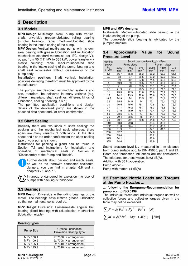
3.4 Approximate Value for Sound Pressure Level Nominal power
PN in kW
Sound pressure level LpA in dB(A) Pump alone Pump + Motor
2950 min-1
1450 min-1
975 min-1
2950 min-1
1450 min-1
975 min-1
1,5 66,7 65,8 65,3 68,2 66,0 65,5 2,2 68 67 66,5 69,2 67,2 66,7 3 69 68,1 67,6 71,5 68,3 68,5 4 69,9 69 68,5 72,1 69,2 69,2
5,5 71 70 69,5 73,1 70,4 70,1 7,5 71,9 71 70,5 73,7 71,3 71,8 11 73,3 72,3 71,8 75,0 73,2 72,8 15 74,2 73,3 72,8 75,6 74,0 74,0
18,5 74,9 74 73,5 76,1 74,6 76,3 22 75,5 74,5 74 77,1 75,1 76,5 30 76,5 75,6 75,1 77,8 76,1 75,7 37 77,1 76,2 75,7 78,3 76,8 76,4 45 77,9 76,9 76,4 79,4 77,4 76,8 55 78,5 77,5 77 80,1 78,0 77,3 75 79,4 78,5 78 81,4 78,9 78,4 90 80,1 79,1 78,6 81,8 79,4 79,0 110 80,8 79,8 83,4 80,2 132 81,3 80,4 83,7 80,8 160 81,9 81 84,1 81,3 200 82,7 84,6 250 83,4 86,2 315 84,1 86,6 355 84,6 86,9
Sound pressure level LpA measured in 1 m distance from pump surface acc. to DIN 45635, part 1 and 24. Room and foundation influences are not considered. The tolerance for these values is ±3 dB(A). Addition with 60 Hz-operation: Pump alone: − Pump with motor: +4 dB(A)
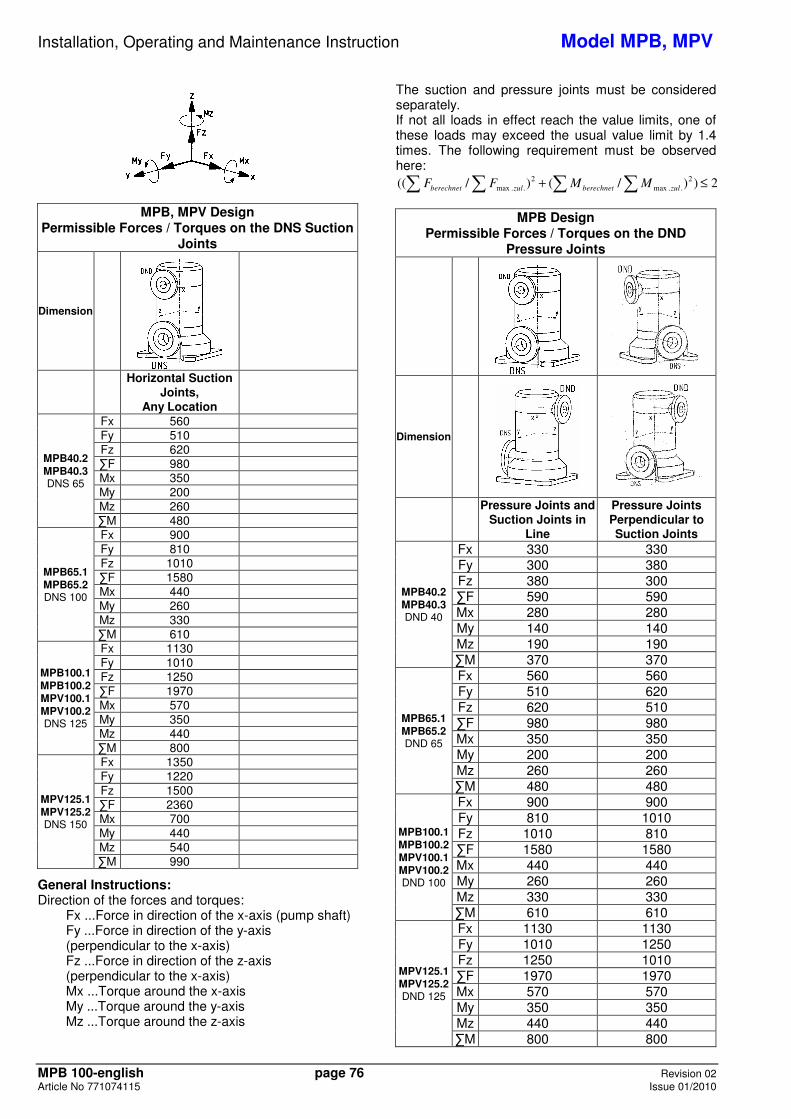
3.5 Permitted Nozzle Loads and Torques at the Pump Nozzles ... ... following the Europump-Recommendation for pump acc. to ISO 5199. The individual forces and individual torques as well as collective forces and collective torques given in the table may not be exceeded.
� ++= ][)(222
NFzFyFxF
� ++= ][)(222
NmMzMyMxM
Installation, Operating and Maintenance Instruction Model MPB, MPV
MPB 100-english page 76 Revision 02 Article No 771074115 Issue 01/2010
MPB, MPV Design Permissible Forces / Torques on the DNS Suction
Joints
Dimension
Horizontal Suction
Joints, Any Location
MPB40.2 MPB40.3 DNS 65
Fx 560 Fy 510 Fz 620 �F 980 Mx 350 My 200 Mz 260 �M 480
MPB65.1 MPB65.2 DNS 100
Fx 900 Fy 810 Fz 1010 �F 1580 Mx 440 My 260 Mz 330 �M 610
MPB100.1 MPB100.2 MPV100.1 MPV100.2 DNS 125
Fx 1130 Fy 1010 Fz 1250 �F 1970 Mx 570 My 350 Mz 440 �M 800
MPV125.1 MPV125.2 DNS 150
Fx 1350 Fy 1220 Fz 1500 �F 2360 Mx 700 My 440 Mz 540 �M 990
General Instructions: Direction of the forces and torques: Fx ...Force in direction of the x-axis (pump shaft) Fy ...Force in direction of the y-axis
(perpendicular to the x-axis) Fz ...Force in direction of the z-axis
(perpendicular to the x-axis) Mx ...Torque around the x-axis
My ...Torque around the y-axis
Mz ...Torque around the z-axis
The suction and pressure joints must be considered separately. If not all loads in effect reach the value limits, one of these loads may exceed the usual value limit by 1.4 times. The following requirement must be observed here:
� � � � ≤+ 2))/()/((2
..max
2
..max zulberechnetzulberechnet MMFF
MPB Design
Permissible Forces / Torques on the DND Pressure Joints
Dimension
Pressure Joints and
Suction Joints in Line
Pressure Joints Perpendicular to Suction Joints
MPB40.2 MPB40.3 DND 40
Fx 330 330 Fy 300 380 Fz 380 300 �F 590 590 Mx 280 280 My 140 140 Mz 190 190 �M 370 370
MPB65.1 MPB65.2 DND 65
Fx 560 560 Fy 510 620 Fz 620 510 �F 980 980 Mx 350 350 My 200 200 Mz 260 260 �M 480 480
MPB100.1 MPB100.2 MPV100.1 MPV100.2 DND 100
Fx 900 900 Fy 810 1010 Fz 1010 810 �F 1580 1580 Mx 440 440 My 260 260 Mz 330 330 �M 610 610
MPV125.1 MPV125.2 DND 125
Fx 1130 1130 Fy 1010 1250 Fz 1250 1010 �F 1970 1970 Mx 570 570 My 350 350 Mz 440 440 �M 800 800
Installation, Operating and Maintenance Instruction Model MPB, MPV
MPB 100-english page 77 Revision 02 Article No 771074115 Issue 01/2010
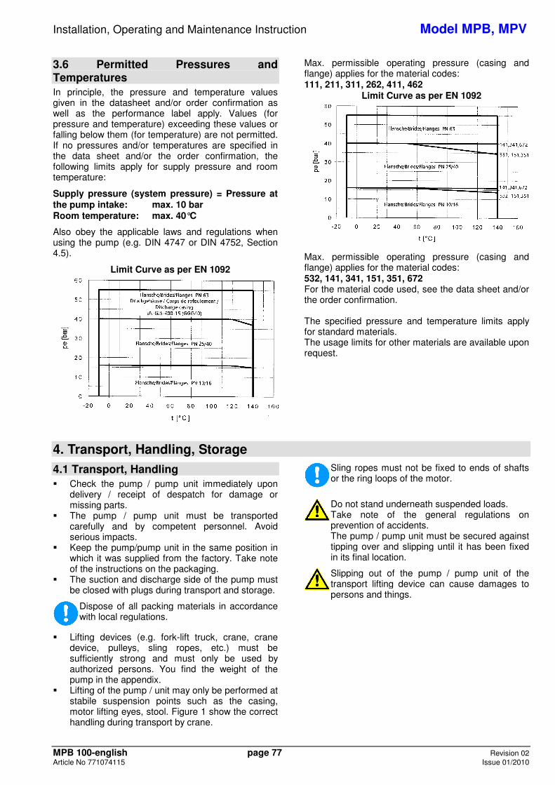
3.6 Permitted Pressures and Temperatures In principle, the pressure and temperature values given in the datasheet and/or order confirmation as well as the performance label apply. Values (for pressure and temperature) exceeding these values or falling below them (for temperature) are not permitted. If no pressures and/or temperatures are specified in the data sheet and/or the order confirmation, the following limits apply for supply pressure and room temperature:
Supply pressure (system pressure) = Pressure at the pump intake: max. 10 bar Room temperature: max. 40°C
Also obey the applicable laws and regulations when using the pump (e.g. DIN 4747 or DIN 4752, Section 4.5).
Limit Curve as per EN 1092
Max. permissible operating pressure (casing and flange) applies for the material codes: 111, 211, 311, 262, 411, 462
Limit Curve as per EN 1092
Max. permissible operating pressure (casing and flange) applies for the material codes: 532, 141, 341, 151, 351, 672 For the material code used, see the data sheet and/or the order confirmation. The specified pressure and temperature limits apply for standard materials. The usage limits for other materials are available upon request.
4. Transport, Handling, Storage
4.1 Transport, Handling � Check the pump / pump unit immediately upon
delivery / receipt of despatch for damage or missing parts.
� The pump / pump unit must be transported carefully and by competent personnel. Avoid serious impacts.
� Keep the pump/pump unit in the same position in which it was supplied from the factory. Take note of the instructions on the packaging.
� The suction and discharge side of the pump must be closed with plugs during transport and storage.
Dispose of all packing materials in accordance with local regulations.
� Lifting devices (e.g. fork-lift truck, crane, crane device, pulleys, sling ropes, etc.) must be sufficiently strong and must only be used by authorized persons. You find the weight of the pump in the appendix.
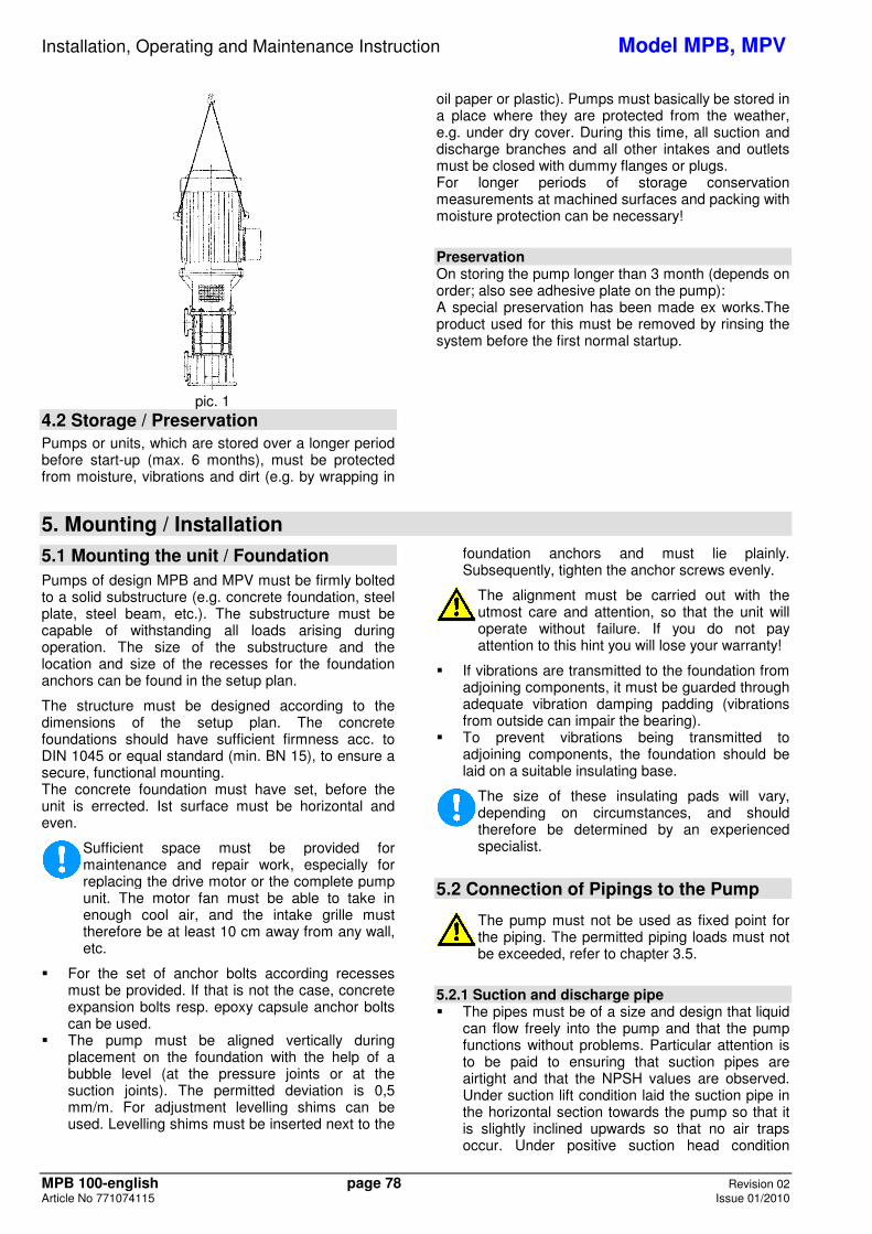
� Lifting of the pump / unit may only be performed at stabile suspension points such as the casing, motor lifting eyes, stool. Figure 1 show the correct handling during transport by crane.
Sling ropes must not be fixed to ends of shafts or the ring loops of the motor.
Do not stand underneath suspended loads. Take note of the general regulations onprevention of accidents. The pump / pump unit must be secured against tipping over and slipping until it has been fixed in its final location.
Slipping out of the pump / pump unit of the transport lifting device can cause damages to persons and things.
Installation, Operating and Maintenance Instruction Model MPB, MPV
MPB 100-english page 78 Revision 02 Article No 771074115 Issue 01/2010
pic. 1
4.2 Storage / Preservation Pumps or units, which are stored over a longer period before start-up (max. 6 months), must be protected from moisture, vibrations and dirt (e.g. by wrapping in
oil paper or plastic). Pumps must basically be stored in a place where they are protected from the weather, e.g. under dry cover. During this time, all suction and discharge branches and all other intakes and outlets must be closed with dummy flanges or plugs. For longer periods of storage conservation measurements at machined surfaces and packing with moisture protection can be necessary!
Preservation On storing the pump longer than 3 month (depends on order; also see adhesive plate on the pump): A special preservation has been made ex works.The product used for this must be removed by rinsing the system before the first normal startup.
5. Mounting / Installation
5.1 Mounting the unit / Foundation
Pumps of design MPB and MPV must be firmly bolted to a solid substructure (e.g. concrete foundation, steel plate, steel beam, etc.). The substructure must be capable of withstanding all loads arising during operation. The size of the substructure and the location and size of the recesses for the foundation anchors can be found in the setup plan.
The structure must be designed according to the dimensions of the setup plan. The concrete foundations should have sufficient firmness acc. to DIN 1045 or equal standard (min. BN 15), to ensure a secure, functional mounting. The concrete foundation must have set, before the unit is errected. Ist surface must be horizontal and even.
Sufficient space must be provided for maintenance and repair work, especially for replacing the drive motor or the complete pump unit. The motor fan must be able to take in enough cool air, and the intake grille must therefore be at least 10 cm away from any wall, etc.
� For the set of anchor bolts according recesses must be provided. If that is not the case, concrete expansion bolts resp. epoxy capsule anchor bolts can be used.
� The pump must be aligned vertically during placement on the foundation with the help of a bubble level (at the pressure joints or at the suction joints). The permitted deviation is 0,5 mm/m. For adjustment levelling shims can be used. Levelling shims must be inserted next to the
foundation anchors and must lie plainly. Subsequently, tighten the anchor screws evenly.
The alignment must be carried out with the utmost care and attention, so that the unit will operate without failure. If you do not pay attention to this hint you will lose your warranty!
� If vibrations are transmitted to the foundation from adjoining components, it must be guarded through adequate vibration damping padding (vibrations from outside can impair the bearing).
� To prevent vibrations being transmitted to adjoining components, the foundation should be laid on a suitable insulating base.
The size of these insulating pads will vary, depending on circumstances, and should therefore be determined by an experienced specialist.
5.2 Connection of Pipings to the Pump
The pump must not be used as fixed point for the piping. The permitted piping loads must not be exceeded, refer to chapter 3.5.
5.2.1 Suction and discharge pipe � The pipes must be of a size and design that liquid
can flow freely into the pump and that the pump functions without problems. Particular attention is to be paid to ensuring that suction pipes are airtight and that the NPSH values are observed. Under suction lift condition laid the suction pipe in the horizontal section towards the pump so that it is slightly inclined upwards so that no air traps occur. Under positive suction head condition
Installation, Operating and Maintenance Instruction Model MPB, MPV
MPB 100-english page 79 Revision 02 Article No 771074115 Issue 01/2010
install the suction pipe work slightly declined towards the pump. Do not install fittings or elbows right before the suction nozzle.
� When laying the pipes, make sure that the pump is accessible for maintenance, installation and disassembly.
� Notice "Permitted Forces on Flanges" (chapter 3.5).
� If expansion joints are used in the pipes, they have to be supported in such a way that the pump is not loaded unduly high because of the pressure in the pipes.
� Before connecting up to pump: remove protective coverings from suction and discharge branches.
� Before starting up, the pipe system, fittings and equipment must be cleaned to remove weld spatter, scale etc. Any pollutants are to be completely removed from pump units that are directly or indirectly connected to drinking water systems before being installed and taken into use.
� To protect the shaft sealing (especially mechanical seals) against foreign impurities, it is recommended that a sieve, 800 micron, is installed in the suction/intake pipe when the motor is being started up.
� If the pipe system is tested with the pump installed, do not exceed the maximum permitted casing pressure of the pump and/or shaft sealing (see data sheet).
� When emptying the pipe after the pressure test, make sure that the pump is treated properly (danger of rust and problems when starting up).
� In the case of pumps with stuffing boxes, replace packing after pressure test (packing may be over-compressed and thus no longer suitable for use).
5.2.2 Additional connections Any required sealing, flushing or cooling pipe connections must be installed. Please consult the data sheet to see which pipes, pressures and amounts are necessary. See the drawings in the enclosures for the location and size of the connections to the pump.
These connections are essential for the function!
It is recommended that a pipeline is installed to take off any leakage from the shaft seal. For connection, see appendix, "Connections".
5.3 Coupling
Make sure that nobody can start the motor during work on the coupling. According to Accident Prevention Regulations, the pump unit may only be operated when the coupling guard is mounted.
With pump units (i.e. pump with motor) supplied complete, no work is required on the coupling before use.
5.3.1 Coupling – MPB Design The pump and motor are rigidly connected together, meaning that no adjustment work is required if the motor is replaced properly.
5.3.2 Coupling – MPV Design If the pump unit is not completely assembled until it reaches its place of use and no separate operating instructions have been supplied by the manufacturer, you should proceed according to the following points: � Before starting installation, carefully clean shaft
ends and coupling components. � Pull coupling onto shaft end, do not hit. The
coupling may be heated beforehand in an oil bath to approx. 100°C (pulling on is then easier). Remove rubber packs from coupling section first.
� Keep the axial distance from both of the coupling halfs.
� The coupling sections must be flush with the shaft end surfaces.
� Mount coupling guard.
On operation in zone 1 and 2 a coupling with valid Atex-certification must be used.
The Operating Instructions of the manufacturer must be followed. Aligning of the coupling is not necessary.
5.3.3 Coupling Guard
Acc. to accident prevention regulations the pump must only be operated with coupling guard.
Care has to be taken, that the used coupling guard consists of non-sparking material.
5.4 Drive On selecting the motor size care has to be taken, that the requirements acc. to ISO 5199 are fulfilled. The Operating Instructions of the manufacturer must be followed.
On application in zone 1 and 2 a motor with valid Atex-certification must be used.
5.5 Electric Connection
Electrical connection work may only be carried out by an authorised professional. The rules and regulations valid for electrical technology, especially those concerned with safety measures, must be observed. The regulations of the national power supply companies operating in that area must also be observed.
Before starting work, check that the information on the motor name plate is the same as the local mains network. The power supply cable of the coupled drive motor must be connected up in accordance with the wiring diagram produced by the motor manufacturer. A protective motor switch must be provided.
Installation, Operating and Maintenance Instruction Model MPB, MPV
MPB 100-english page 80 Revision 02 Article No 771074115 Issue 01/2010
In areas endangered to explosion IEC 60079-14 must additionally be noticed for the electric installation.
The direction of rotation must only be checked when the pump is full. Dry running will cause damage to the pump.
5.6 Final Control Check alignment of coupling acc. to chapter 5.3.1 again. It must be possible to turn the unit easily by hand at the coupling.
6. Start-up, Operation, Shut down
The plant may only be started up by people who are familiar with the local safety regulations and with these Operating Instructions (especially with the safety regulations and safety instructions given here).
Hints for the use as boiler feed pump Limits for cast iron when used in boiler feed or condensate applications: pH-value ≥ 9,0 (optimum ≥ 9,3), short term: pH-value ≥ 8,5. The above stated values must be guarantied at the suction side of the pump in any case. The water treatment must be in acc. with the specifications for water treatment of boiler feed water in steam plants up to 64 bar. Air traps in the system must be avoided in any case.
6.1 Initial start-up Before starting up the pump, check, if the following points were controlled and carried out: � With pumps of designs MPB and MPV, no
additional lubrication measures are required before the first startup.
� Pump and suction pipe must be filled completely with liquid when starting up. Open the screwed plug "PM2" for filling. Close them when water is flowing out.
� Turn pump unit once again by hand and check that it moves smoothly and evenly.
� Check that coupling guard is installed and that all safety devices are operational.
� Switch on any sealing, flushing or cooling devices that are provided. See Data Sheet for quantity and pressure.
� Open valve in suction /intake pipe. � Set the pressure-side slider to approx. 25% of the
pump rate for which the system was designed. For pumps with a drive output lower than 30 kW, the slider may also remain closed briefly upon startup.
� Secure, that unit is electrically connected acc. to all regulations and with all safety devices.
� Check direction of rotation by switching on and off briefly. It must be the same as the directional arrow on the bearing frame.
6.2 Switch on drive � Immediately (max. 10 seconds on 50 Hz resp.
max. 7 seconds on 60 Hz currency feed) after reaching normal operating speed open discharge valve adjust the required operating point. The pumping data shown at the type plate resp. in the
data sheet and / or the order confirmation must be met. Every change is only permitted after talking with the manufacturer!
Operation with closed valve in the suction and / or discharge piping is not permitted.
On starting-up without back-pressure, the back-pressure must be produced through throttling at the discharge side. After reaching full back-pressure open valve
In order that the shaft sealing can be monitored and maintained unhindered, no protection cover is provided in this area. Therefore special attention is required when pump is working (no long hair, loose clothes, a.s.o.).
� Packing: Packing need leakage for trouble free function (drop wise outlet of pumped medium). Adjust ample leakage in the beginning. Reduce that slowly during the first operating hours by continuously fastening of gland (see position "69" and "M3" in sectional drawing) when pump is running. Assume 60-100 drops / minute as approx. value. The leakage must flow out liquid in any case (not vaporous).
Packing that run dry will harden and then destroy the shaft sleeve and/or the shaft.
� Mechanical seals: Mech. seals don't need to be maintained and are almost free of leakage.
If pump does not reach attended head or if atypical sounds or vibrations do occur: Switch off pump (see chapter 6.7) and seek for causes (see chapter 10).
6.3 Restarting Basically, the same procedure should be followed as for starting up for the first time. However, there is no need to check the direction of rotation and the accessibility of the pump unit. The pump should only be automatically restarted if it has been made sure that the pump has remained filled whilst stand by.
Installation, Operating and Maintenance Instruction Model MPB, MPV
MPB 100-english page 81 Revision 02 Article No 771074115 Issue 01/2010
Be particularly careful not to touch hot machine parts and when working in the unprotected shaft seal area. Remember that automatically controlled systems may switch themselves on suddenly at any time. Suitable warning signs should be affixed.
6.4 Limits of Operation
The operating limits of the pump / unit regarding pressure, temperature, performance and speed are shown in the data sheet and / or order confirmation and must be observed under any circumstances!
� Do not exceed the output given on the motor name plate.
� Avoid sudden changes in temperature (temperature shocks).
� The pump and motor should run evenly and without vibrations; check at least once a week.
6.4.1 Flow min. / max. If no other data are given in the curves or data sheets, the following is valid:
Qmin = 0,1 x QBEP for for short time operation Qmin = 0,3 x QBEP for continuous operation Qmax = 1,2 x QBEP for continuous operation *)
QBEP = Flow in efficiency optimum *) on condition that NPSHfacility > (NPSHpump + 0,5 m)
6.4.2 Abrasive Media
On pumping liquids with abrasive components an increased wear at hydraulic and shaft sealing must be expected. The intervals of inspection should be reduced compared to the usual times.
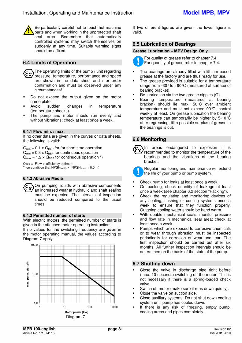
6.4.3 Permitted number of starts With electric motors, the permitted number of starts is given in the attached motor operating instructions. If no values for the switching frequency are given in the motor operating manual, the values according to Diagram 7 apply. 3
1,0
10,0
100,0
1 10 100 1000
Motor power [kW]
max
. per
m. s
tart
s/h
Diagram 7
If two different figures are given, the lower figure is valid.
6.5 Lubrication of Bearings
Grease Lubrication – MPV Design Only
For quality of grease refer to chapter 7.4. For quantity of grease refer to chapter 7.4.
� The bearings are already filled with lithium based grease at the factory and are thus ready for use.
� The grease provided is suitable for a temperature range from -30° to +90°C (measured at surface of bearing bracket).
� Re-lubrication via the two grease nipples (G). � Bearing temperature (measured at bearing
bracket) should lie max. 50°C over ambient temperature and must not exceed 90°C, control weekly at least. On grease lubrication the bearing temperature can temporarily be higher by 5-10°C after regreasing, till a possible surplus of grease in the bearings is cut.
6.6 Monitoring
In areas endangered to explosion it is recommended to monitor the temperature of the bearings and the vibrations of the bearing bracket.
Regular monitoring and maintenance will extend the life of your pump or pump system.
� Check pump for leaks at least once a week. � On packing, check quantity of leakage at least
once a week (see chapter 6.2 section "Packing"). � Check the regulating and monitoring devices of
any sealing, flushing or cooling systems once a week to ensure that they function properly. Outgoing cooling water should be hand warm.
� With double mechanical seals, monitor pressure and flow rate in mechanical seal area; check at least once a week.
� Pumps which are exposed to corrosive chemicals or to wear through abrasion must be inspected periodically for corrosion or wear and tear. The first inspection should be carried out after six months. All further inspection intervals should be determined on the basis of the state of the pump.
6.7 Shutting down � Close the valve in discharge pipe right before
(max. 10 seconds) switching off the motor. This is not necessary if there is a spring-loaded check valve.
� Switch off motor (make sure it runs down quietly). � Close the valve on suction side. � Close auxiliary systems. Do not shut down cooling
system until pump has cooled down. � If there is any risk of freezing, empty pump,
cooling areas and pipes completely.
Installation, Operating and Maintenance Instruction Model MPB, MPV
MPB 100-english page 82 Revision 02 Article No 771074115 Issue 01/2010
� If the pump also remains under operating conditions (pressure and temperature) when stationary, leave all sealing, flushing and cooling systems switched on.
� The shaft sealing must remain sealed if there is a risk of air being sucked in (in the event of supply from vacuum systems or parallel operation with shared suction pipe).
6.8 Storage / longer periods of non-operation
6.8.1 Storage of new pumps If the putting into operation shall happen a longer period after the delivery, we recommend the following measures for the storage of the pump: � Store pump at a dry place. � Rotate pump by hand at least once a month.
6.8.2 Measures for longer putting out of operation Pump remains installed and in ready for operation: � Test runs of 5 min. duration must be made in
regular intervals. The span between the test runs is depending on the plant. However, it should be made once a week, at least.
6.8.3 Longer periods of non-operation
After long stationary periods, packing may have hardened; these must be replaced before start-up. When starting up, follow the instructions for starting up for the first time (see chapter 6)!
a) Filled pumps � Switch stand-by pumps on and immediately off
again once a week. Possibly use as main pump. � If the stand-by pump is at operating pressure and
temperature, leave all sealing, flushing and cooling systems switched on.
� MPV Design: Replace the grease in the bearings after 2 years.
� Stopfbuchspackung nicht bis zur Leckagefreiheit festziehen.
b) Drained pumps � Turn shaft at least 1x week (do not switch on
because of dry running). � MPV Design: Replace the grease in the bearings
after 2 years.
7. Servicing, Maintenance
7.1 General remarks
Maintenance and servicing work must only be carried out by trained, experienced staff who are familiar with the contents of these Operating Instructions, or by the Manufacturer's own service staff.
Work should only be carried out on the pump or pump unit when it is not in operation. You must observe chapter 2.
7.2 Mechanical seals
Before opening the pump, it is essential that you note chapter 2 and chapter 8.
If the liquid being handled leaks out at the mechanical seal, it is damaged and must be replaced. Replace the mechanical seal according to Section 8.6 "Replacing the Shaft Seal". Mech. seals do not need to be maintained and are completely free of leakage. Pumps with mech. seals must only be operated when completely filled and vented. The mechanical seal chamber must always remain filled with liquid during operation of the pump. If the liquid being handled drips out at the mechanical seal, it is damaged and must be replaced. When installing the mechanical seal make sure that the seal casing is absolutely clean, particular care has to be paid to the surface of the seal rings. To facilitate the slip-on of the rotating components of the seal onto the shaft lubricate all moving components and sliding areas by means of water, soapy water or soft soap. Use mineral oils only in case all elastomers are oil
resistant. Do not lubricate the surface of the seal rings. Do not force elastomeric elements over sharp edges, if necessary use assembling aiding sleeves.
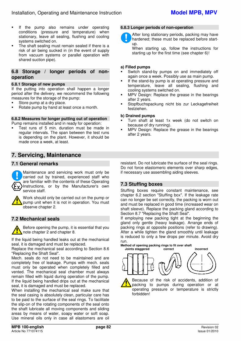
7.3 Stuffing boxes Stuffing boxes require constant maintenance, see chapter 6.2 section "Stuffing box". If the leakage rate can no longer be set correctly, the packing is worn out and must be replaced in good time (increased wear on shaft sleeve). Replace the packing gland according to Section 8.7 "Replacing the Shaft Seal". If employing new packing tight at the beginning the gland only gentle (heavy leakage). Arrange ends of packing rings at opposite positions (refer to drawing). After a while tighten the gland smoothly until leakage is reduced to only a few drops per minute. Avoid dry run. Method of opening packing rings to fit over shaft Joints staggered correct incorrect
Because of the risk of accidents, addition of packing to pumps during operation or at operating pressure or temperature is strictly forbidden!
Installation, Operating and Maintenance Instruction Model MPB, MPV
MPB 100-english page 83 Revision 02 Article No 771074115 Issue 01/2010
7.4 Lubrication and Change of Lubricant
7.4.1 Grease Lubrication – MPV Design Only Re-greasing � Grease lubricated bearings with the possibility of
re-greasing must be re-lubricated all 4000 operating hours, but at least 1x year. Clean lubricating nipples (G) first.
Lubricating grease quality ... ... K2K-20, KP2K-20, etc. as per DIN 51825:
- Lithium soap grease - NLGI GRADE 2 - Temperature range -20 to 120 °C - Dripping point > 175 °C - Base oil viscosity 70 to 150 mm²/s at 40 °C
When changing the grease type, ensure compatibility with the residual grease.
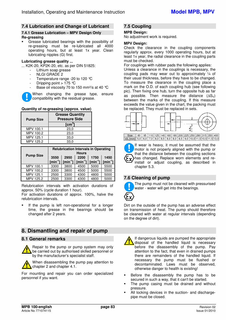
Quantity of re-greasing (approx. value)
Pump Size Grease Quantity Pressure Side
[cm3] MPV 100.1 23,0 MPV 100.2 23,0 MPV 125.1 33,0 MPV 125.2 33,0
Pump Size
Relubrication Intervals in Operating Hours
3550 2950 2200 1750 1450 [min-1] [min-1] [min-1] [min-1] [min-1]
MPV 100.1 3300 3800 4500 5000 5500 MPV 100.2 3300 3800 4500 5000 5500 MPV 125.1 2500 3300 4300 4800 5000 MPV 125.2 2500 3300 4300 4800 5000
Relubrication intervals with activation durations of approx. 50% (cycle duration 1 hour). For activation durations of approx. 100%, halve the relubrication intervals.
� If the pump is left non-operational for a longer time, the grease in the bearings should be changed after 2 years.
7.5 Coupling MPB Design: No adjustment work is required.
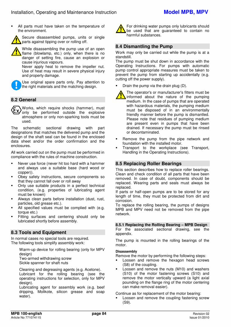
MPV Design: Check the clearance in the coupling components regularly approx. every 1000 operating hours, but at least 1x year, the radial clearance in the coupling parts must be checked. For couplings with rubber pads the following applies: Unless a clearance in the couplings is necessary, the coupling pads may wear out to approximately ¼ of their usual thickness, before they have to be changed. To measure the clearance in the coupling place a mark on the O.D. of each coupling hub (see following pic). Then fixing one hub, turn the opposite hub as far as possible. Then measure the distance (∆SV) between the marks of the coupling. If this measure exceeds the value given in the chart, the packing must be replaced. They must be replaced in sets.
Size 80 95 110 125 140 160 180 200 225 250 280 315 350 400 ∆Sv [mm] 5,0 6,0 7,0 8,0 8,5 8,0 8,0 8,5 9,0 10,0 11,5 10,5 11,5 13,0
If wear is heavy, it must be assumed that the motor is not properly aligned with the pump or that the distance between the coupling sections has changed. Replace worn elements and re-install or adjust coupling, as described in chapter 5.3.
7.6 Cleaning of pump
The pump must not be cleaned with pressurised water - water will get into the bearings.
Dirt on the outside of the pump has an adverse effect on transmission of heat. The pump should therefore be cleaned with water at regular intervals (depending on the degree of dirt).
8. Dismantling and repair of pump
8.1 General remarks
Repair to the pump or pump system may only be carried out by authorised skilled personnel or by the manufacturer’s specialist staff.
When disassembling the pump pay attention tochapter 2 and chapter 4.1.
For mounting and repair you can order specialized personnel if you want.
If dangerous liquids are pumped the appropriate disposal of the handled liquid is necessary before the disassembly of the pump. Pay attention to the fact, that even in drained pumps there are remainders of the handled liquid. If necessary the pump must be flushed or decontaminated. Laws must be observed, otherwise danger to health is existing!
� Before the disassembly the pump has to be secured in such a way, that it can't be started.
� The pump casing must be drained and without pressure.
� All locking devices in the suction- and discharge-pipe must be closed.
Installation, Operating and Maintenance Instruction Model MPB, MPV
MPB 100-english page 84 Revision 02 Article No 771074115 Issue 01/2010
� All parts must have taken on the temperature of the environment.
Secure disassembled pumps, units or single parts against tipping over or rolling off.
While disassembling the pump use of an open flame (blowlamp, etc.) only, when there is no danger of setting fire, cause an explosion or cause injurious vapours. Never apply heat to remove the impeller nut. Use of heat may result in severe physical injury and property damage.
Use original spare parts only. Pay attention to the right materials and the matching design.
8.2 General
Works, which require shocks (hammer), must only be performed outside the explosive atmosphere or only non-sparking tools must be used.
The schematic sectional drawing with part designations that matches the delivered pump and the design of the shaft seal can be found in the enclosed data sheet and/or the order confirmation and the enclosures.
All work carried out on the pump must be performed in compliance with the rules of machine construction.
� Never use force (never hit too hard with a hammer and always use a suitable base (hard wood or copper)).
� Obey safety instructions, secure components so that they cannot fall over or roll away
� Only use suitable products in a perfect technical condition, (e.g. properties of lubricating agent must be known)
� Always clean parts before installation (dust, rust, particles, old grease etc.).
� All specified values must be complied with (e.g. torque etc.)
� Fitting surfaces and centering should only be lubricated shortly before assembly.
8.3 Tools and Equipment In normal cases no special tools are required.
The following tools simplify assembly work:
Warm-up device for rolling bearing (only for MPV design) Two-armed withdrawing screw Sickle spanner for shaft nuts
Cleaning and degreasing agents (e.g. Acetone). Lubricant for the rolling bearing (see the operating instructions for selection, only for MPV design). Lubricating agent for assembly work (e.g. beef dripping, Molikote, silicon grease and soap water).
For drinking water pumps only lubricants should be used that are guaranteed to contain no harmful substances.
8.4 Dismantling the Pump Work may only be carried out while the pump is at a standstill. The pump must be shut down in accordance with the Operating Instructions. For pumps with automatic pump control appropriate measures must be taken to prevent the pump from starting up accidentally (e.g. cutting off the power supply).
� Drain the pump via the drain plug (D).
The operator's or manufacturer's fitters must be informed about the nature of the pumping medium. In the case of pumps that are operated with hazardous materials, the pumping medium must be disposed of in an environmentally friendly manner before the pump is dismantled. Please note that residues of pumping medium are present even in pumps that have been drained. If necessary the pump must be rinsed or decontaminated.
� Remove the pump from the pipe network and foundation with the installed motor.
� Transport to the workplace (see Transport, Handling in the Operating Instructions).
8.5 Replacing Roller Bearings This section describes how to replace roller bearings. Clean and check condition of all parts that have been removed. In case of doubt, components should be replaced. Wearing parts and seals must always be replaced. If parts or half-open pumps are to be stored for any length of time, they must be protected from dirt and corrosion. To replace the rolling bearing, the pumps of designs MPB and MPV need not be removed from the pipe network.
8.5.1 Replacing the Rolling Bearing – MPB Design For the associated sectional drawing, see the appendix.
The pump is mounted in the rolling bearings of the motor.
Disassembly Remove the motor by performing the following steps: � Loosen and remove the hexagon head screws
(S8) of the coupling. � Loosen and remove the nuts (M10) and washers
(S10) of the motor fastening screws (S10) and remove the motor vertically upward (a light axial pounding on the flange ring of the motor centering can make removal easier).
Continue as for replacement of the motor bearing: � Loosen and remove the coupling fastening screw
(S9).
Installation, Operating and Maintenance Instruction Model MPB, MPV
MPB 100-english page 85 Revision 02 Article No 771074115 Issue 01/2010
� Pull the coupling half (7/M) off the motor shaft with a withdrawing screw.
� Replace the motor bearing according to the repair manual of the motor.
Assembly � Mount the coupling half (7/M) onto the motor shaft
as described in Section 5.3.2 "Coupling – MPV Design) and tighten the coupling fastening screw (S9).
� Then reassemble the motor in reverse of the disassembly order and reconnect the coupling halves with the hexagon head screws (S8).
8.5.2 Replacing the Rolling Bearing – MPV Design For the associated sectional drawing, see the appendix.
Disassembly � Remove the motor. � Remove the thrower (73M) and put the thrower
(73P) back in place. � Screw off nuts (M1) and nuts (M5), loosen the
bearing cover (12) from the bearing pedestal (8) and slide downward.
� Lift away the bearing pedestal (8) upward (a slight axial pounding on the bearing pedestal (8) will make it easier to pull off)
After removing the bearing pedestal (8), the shaft will move freely in the axial direction (approx. 3 – 4 mm). Standard shaft seals can take up this play without impairing their function. For special shaft seals (e.g. cartridge seals), please follow the seal operating instructions.
� Unscrew shaft nuts (50) (sickle spanner). The shaft nut has a securing device to prevent it coming loose.
� If this securing device is no longer adequate, the nut must be replaced.
� Remove roller bearings (K) with the withdrawing screw.
� Check the surface of the shaft for damage, grind away any furrows.
Assembly � Clean the fitting surfaces between the bearing
pedestal (8) and pressure casing (4) and coat them with lubricant.
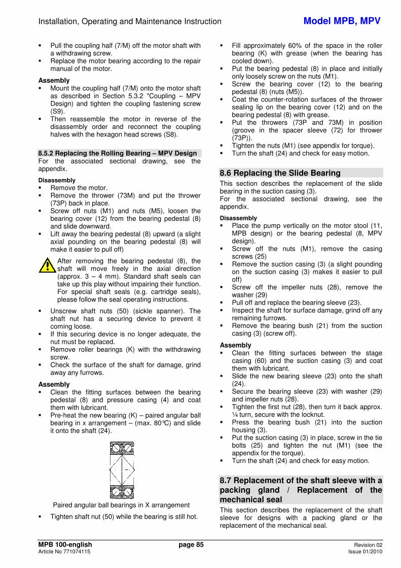
� Pre-heat the new bearing (K) – paired angular ball bearing in x arrangement – (max. 80°C) and slide it onto the shaft (24).
Paired angular ball bearings in X arrangement
� Tighten shaft nut (50) while the bearing is still hot.
� Fill approximately 60% of the space in the roller bearing (K) with grease (when the bearing has cooled down).
� Put the bearing pedestal (8) in place and initially only loosely screw on the nuts (M1).
� Screw the bearing cover (12) to the bearing pedestal (8) (nuts (M5)).
� Coat the counter-rotation surfaces of the thrower sealing lip on the bearing cover (12) and on the bearing pedestal (8) with grease.
� Put the throwers (73P and 73M) in position (groove in the spacer sleeve (72) for thrower (73P)).
� Tighten the nuts (M1) (see appendix for torque). � Turn the shaft (24) and check for easy motion.
8.6 Replacing the Slide Bearing This section describes the replacement of the slide bearing in the suction casing (3). For the associated sectional drawing, see the appendix.
Disassembly � Place the pump vertically on the motor stool (11,
MPB design) or the bearing pedestal (8, MPV design).
� Screw off the nuts (M1), remove the casing screws (25)
� Remove the suction casing (3) (a slight pounding on the suction casing (3) makes it easier to pull off)
� Screw off the impeller nuts (28), remove the washer (29)
� Pull off and replace the bearing sleeve (23). � Inspect the shaft for surface damage, grind off any
remaining furrows. � Remove the bearing bush (21) from the suction
casing (3) (screw off).
Assembly � Clean the fitting surfaces between the stage
casing (60) and the suction casing (3) and coat them with lubricant.
� Slide the new bearing sleeve (23) onto the shaft (24).
� Secure the bearing sleeve (23) with washer (29) and impeller nuts (28).
� Tighten the first nut (28), then turn it back approx. ¼ turn, secure with the locknut.
� Press the bearing bush (21) into the suction housing (3).
� Put the suction casing (3) in place, screw in the tie bolts (25) and tighten the nut (M1) (see the appendix for the torque).
� Turn the shaft (24) and check for easy motion.
8.7 Replacement of the shaft sleeve with a packing gland / Replacement of the mechanical seal This section describes the replacement of the shaft sleeve for designs with a packing gland or the replacement of the mechanical seal.
Installation, Operating and Maintenance Instruction Model MPB, MPV
MPB 100-english page 86 Revision 02 Article No 771074115 Issue 01/2010
Clean and check condition of all parts that have been removed. In case of doubt, components should be replaced. Wearing parts (roller bearings) and seals must always be replaced. If parts or half-open pumps are to be stored for any length of time, they must be protected from dirt and corrosion.
8.7.1 Model with Packing Gland (Code "P") – MPB Design For the associated sectional drawing, see the appendix.
Disassembly � Remove the motor as described in Section 8.5.1
"Replacing the Rolling Bearing – MPB Design" Disassembly.
� Screw off the shaft nut (50) (sickle wrench), the shaft nut has a lock to prevent loosening.
� If this lock is no longer sufficient, the nut must be replaced.
� Pull off the coupling half (7/P) with the withdrawing screw.
� Remove the key (PF4). � Screw off the nuts (M3) and remove the gland
(69). � Pull out the worn packing ring (P). � Pull off the shaft wearing sleeve (44), pull out the
O-ring (OR4). � Depending on the wear of the running surface
(less than 0.5 mm on the diameter), the shaft wearing sleeve (44) can be evened out (fine lathing and polishing or grinding). In the case of severe wear, the shaft wearing sleeve (44) must be replaced.
� Remove the remains of the packing ring (P) from the gland chamber and clean all other parts. Degrease the shaft (24) and do not yet coat with lubricant.
Assembly � Slide on the O-ring (OR4) and coat with lubricant
(e.g. silicone grease) using a small brush. � Coat the shaft wearing sleeve (44) with lubricant in
the hole so that the O-ring grove remains clean (begin approx. 10-15 mm inside it). The standard O-rings of EP caoutchouc are not resistant to oil-containing lubricants and may not come into contact with such substances. If resistance is ensured (e.g. beef dripping as lubricant or oil-resistant O-rings), the entire shaft (24) can be coated.
� Slide on the shaft wearing sleeve (44), insert new packing rings (P) (see operating manual) and affix lightly with the gland (69) (nuts (M3)). When sliding on the shaft wearing sleeve (44), make certain that the O-ring can slip lightly into the groove.
� Insert the key (PF4). � Mount the coupling half (7/M) onto the pump shaft
as described in Section 5.3.2 "Coupling – MPV Design") and tighten the bearing nut screw (50).
� Then assemble the motor according to Section 8.5.1 "Replacing the Rolling Bearing – MPB Design".
8.7.2 Model with Packing Gland (Code "P") – MPV Design For the associated sectional drawing, see the appendix.
Disassembly � Disassemble the pump as described in Section
8.5.2 "Replacing the Rolling Bearing – MPV Design".
� Remove the bearing cover (12), spacer sleeve (72) and thrower (73P).
� Remove the key (PF3). � Screw off the nuts (M3) and remove the gland
(69). � Pull out the worn packing ring (P). � Pull off the shaft wearing sleeve (44), pull out the
O-ring (OR4). � Depending on the wear of the running surface
(less than 0.5 mm on the diameter), the shaft wearing sleeve (44) can be evened out (fine lathing and polishing or grinding). In the case of severe wear, the shaft wearing sleeve (44) must be replaced.
� Remove the remains of the packing ring (P) from the gland chamber and clean all other parts. Degrease the shaft (24) and do not yet coat with lubricant.
Assembly � Slide on the O-ring (OR4) and coat with lubricant
(e.g. silicone grease) using a small brush. � Lubricate the shaft protective sleeve (44) in the
borehole) so that the O-ring groove remains clean (start approx. 10-15mm inside). Standard O-rings made of EP rubber are not resistant to oil emulsive lubricants and must not come into contact with them. Once resistance has been ensured (e.g. beef dripping as lubricating agent or oil resistant O-rings) the entire shaft (24) may be lubricated.
� Slide on the shaft wearing sleeve (44), insert new packing rings (P) (see operating manual) and affix lightly with the gland (69) (nuts (M3)). When sliding on the shaft wearing sleeve (44), make certain that the O-ring can slip lightly into the groove.
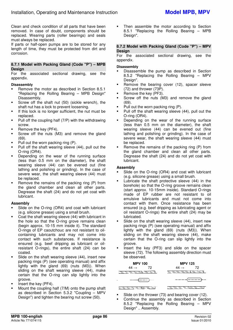
� Insert the key (PF3) and slide on the spacer sleeve (72). The following assembly direction must be observed.
MPV 100 MPV 125 44 � 72 44 � 72
� Slide on the thrower (73) and bearing cover (12). � Continue the assembly as described in Section
8.5.2 "Replacing the Rolling Bearing – MPV Design" .. Assembly.
Installation, Operating and Maintenance Instruction Model MPB, MPV
MPB 100-english page 87 Revision 02 Article No 771074115 Issue 01/2010
8.7.3 Model with Standard Rotating Mechanical Seal (Code "SA, SB, SC, SD, SE and SF") – MPB Design For the associated sectional drawing, see the appendix.
Disassembly � Remove the motor as described in Section 8.5.1
"Replacing the Rolling Bearing – MPB Design" Disassembly.
� Screw off the shaft nut (50) (sickle wrench), the shaft nut has a lock to prevent loosening.
� If this lock is no longer sufficient, the nut must be replaced.
� Pull off the coupling half (7/P) with the withdrawing screw.
� Remove the key (PF4). � Screw off the nuts (M1) and remove the motor
stool (11). � Remove the seal cover (18). Pre-treat the fitting
surface between the seal cover and the casing with a brand name rust remover.
� Pull off the shaft wearing sleeve (44U or 44B), pull out the O-ring (OR4).
� Evenly press the counter-ring of the mechanical seal (GLRD..) out of the seal cover (18).
In the event of a break, very sharp edges can be formed � injury risk
� Slide the rotating unit of the mechanical seal off the shaft wearing sleeve (44..). For mechanical seals with locking screws, loosen these first.
� Clean all parts well and check for wear. In principle, mechanical seals must be replaced. Repair of the mechanical seal is only recommended if performed by an expert.
Assembly � Always use a lubricant when assembling the
mechanical seal. We recommend lubricating the O-ring or rubber gaiter with soapy water just before assembly. Please do not use mineral grease or oil if the O-ring is not resistant to such materials.
� Insert the counter-ring of the mechanical seal (GLRD..) into the seal cover (18). Slide the rotating unit of the mechanical seal (GLRD..) onto the shaft wearing sleeve (44..) and affix it (if possible).
� For mechanical seals with rubber gaiter, the following steps must now be performed quickly. This is the only way to guarantee that the rotating mechanical seal unit can still be moved during installation and will take the correct position.
� Slide on the O-ring (OR4) and coat with lubricant (e.g. silicone grease) using a small brush.
� (e.g. silicone grease) using a small brush. � Lubricate the shaft protective sleeve (44) in the
borehole) so that the O-ring groove remains clean (start approx. 10-15mm inside). Standard O-rings made of EP rubber are not resistant to oil emulsive lubricants and must not come into contact with them. Once resistance has been ensured (e.g. beef dripping as lubricating agent or
oil resistant O-rings) the entire shaft (24) may be lubricated.
� Slide on the shaft wearing sleeve (44), making certain that the O-ring can slip lightly into the groove.
� Insert the O-ring (OR3) into the casing and affix with silicone grease. The O-ring should rest against the outer diameter if possible (the O-ring can be enlarged slightly by pulling on it).
� Position the seal cover (18) carefully, observing the direction of the pin (S4) (groove in the bearing support)
� Put the motor stool (11) in place and tighten the nuts (M1) (see the appendix for the torque).
� Insert the key (PF4). � Mount the coupling half (7/M) onto the pump shaft
as described in Section 5.3.2 "Coupling – MPV Design" and tighten the bearing nut screw (50).
� Then assemble the motor according to Section 8.5.1 "Replacing the Rolling Bearing – MPB Design" .. Assembly.
8.7.4 Model with Standard Rotating Mechanical Seal (Code "SA, SB, SC, SD, SE and SF") – MPV Design For the associated sectional drawing, see the appendix.
Disassembly � Disassemble the pump as described in Section
8.5.2 "Replacing the Rolling Bearing – MPV Design" Disassembly.
� Remove the bearing cover (12), spacer sleeve (72) and thrower (73P).
� Remove the key (PF3). � Screw off the nuts (M1) and remove the bearing
pedestal (8). � Remove the seal cover (18). Pre-treat the fitting
surface between the seal cover and the casing with a brand name rust remover.
� Pull off the shaft wearing sleeve (44U or 44B), pull out the O-ring (OR4).
� Evenly press the counter-ring of the mechanical seal (GLRD..) out of the seal cover (18).
In the event of a break, very sharp edges can be formed � injury risk
� Slide the rotating unit of the mechanical seal off the shaft wearing sleeve (44..). For mechanical seals with locking screws, loosen these first.
� Clean all parts well and check for wear. In principle, mechanical seals must be replaced. Repair of the mechanical seal is only recommended if performed by an expert.
Assembly � Always use a lubricant when assembling the
mechanical seal. We recommend lubricating the O-ring or rubber gaiter with soapy water just before assembly. Please do not use mineral grease or oil if the O-ring is not resistant to such materials.
� Insert the counter-ring of the mechanical seal (GLRD..) into the seal cover (18). Slide the
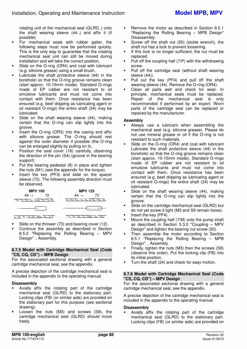
Installation, Operating and Maintenance Instruction Model MPB, MPV
MPB 100-english page 88 Revision 02 Article No 771074115 Issue 01/2010
rotating unit of the mechanical seal (GLRD..) onto the shaft wearing sleeve (44..) and affix it (if possible).
� For mechanical seals with rubber gaiter, the following steps must now be performed quickly. This is the only way to guarantee that the rotating mechanical seal unit can still be moved during installation and will take the correct position.
� Slide on the O-ring (OR4) and coat with lubricant (e.g. silicone grease) using a small brush.
� Lubricate the shaft protective sleeve (44) in the borehole) so that the O-ring groove remains clean (start approx. 10-15mm inside). Standard O-rings made of EP rubber are not resistant to oil emulsive lubricants and must not come into contact with them. Once resistance has been ensured (e.g. beef dripping as lubricating agent or oil resistant O-rings) the entire shaft (24) may be lubricated.
� Slide on the shaft wearing sleeve (44), making certain that the O-ring can slip lightly into the groove.
� Insert the O-ring (OR3) into the casing and affix with silicone grease. The O-ring should rest against the outer diameter if possible (the O-ring can be enlarged slightly by pulling on it).
� Position the seal cover (18) carefully, observing the direction of the pin (S4) (groove in the bearing support)
� Put the bearing pedestal (8) in place and tighten the nuts (M1) (see the appendix for the torque).
� Insert the key (PF3) and slide on the spacer sleeve (72). The following assembly direction must be observed.
MPV 100 MPV 125 44 � 72 44 � 72
� Slide on the thrower (73) and bearing cover (12). � Continue the assembly as described in Section
8.5.2 "Replacing the Rolling Bearing – MPV Design" .. Assembly.
8.7.5 Model with Cartridge Mechanical Seal (Code "CS, CQ, CD") – MPB Design For the associated sectional drawing with a general cartridge mechanical seal, see the appendix.
A precise depiction of the cartridge mechanical seal is included in the appendix to the operating manual.
Disassembly � Axially affix the rotating part of the cartridge
mechanical seal (GLRD) to the stationary part. Locking clips (FB) (or similar aids) are provided on the stationary part for this purpose (see sectional drawing).
� Loosen the nuts (M3) and screws (S9), the cartridge mechanical seal (GLRD) should move freely.
� Remove the motor as described in Section 8.5.1 "Replacing the Rolling Bearing – MPB Design" Disassembly.
� Screw off the shaft nut (50) (sickle wrench), the shaft nut has a lock to prevent loosening.
� If this lock is no longer sufficient, the nut must be replaced.
� Pull off the coupling half (7/P) with the withdrawing screw.
� Pull off the cartridge seal (without shaft wearing sleeve (44)).
� Pull out the key (PF4) and pull off the shaft wearing sleeve (44). Remove the O-ring (OR4).
� Clean all parts well and check for wear. In principle, mechanical seals must be replaced. Repair of the mechanical seal is only recommended if performed by an expert. Worn parts of the cartridge seal can be replaced or repaired by the manufacturer.
Assembly � Always use a lubricant when assembling the
mechanical seal (e.g. silicone grease). Please do not use mineral grease or oil if the O-ring is not resistant to such materials.
� Slide on the O-ring (OR4) and coat with lubricant Lubricate the shaft protective sleeve (44) in the borehole) so that the O-ring groove remains clean (start approx. 10-15mm inside). Standard O-rings made of EP rubber are not resistant to oil emulsive lubricants and must not come into contact with them. Once resistance has been ensured (e.g. beef dripping as lubricating agent or oil resistant O-rings) the entire shaft (24) may be lubricated.
� Slide on the shaft wearing sleeve (44), making certain that the O-ring can slip lightly into the groove.
� Slide on the cartridge mechanical seal (GLRD) but do not yet screw it tight (M3 and S9 remain loose).
� Insert the key (PF4). � Mount the coupling half (7/M) onto the pump shaft
as described in Section 5.3.2 "Coupling – MPV Design" and tighten the bearing nut screw (50).
� Then assemble the motor according to Section 8.5.1 "Replacing the Rolling Bearing – MPB Design" .. Assembly.
� Finally, tighten the nuts (M3) then the screws (S9) (observe this order). Put the locking clip (FB) into its initial position.
� Turn the shaft (24) and check for easy motion.
8.7.6 Model with Cartridge Mechanical Seal (Code "CS, CQ, CD") – MPV Design For the associated sectional drawing with a general cartridge mechanical seal, see the appendix.
A precise depiction of the cartridge mechanical seal is included in the appendix to the operating manual.
Disassembly � Axially affix the rotating part of the cartridge
mechanical seal (GLRD) to the stationary part. Locking clips (FB) (or similar aids) are provided on
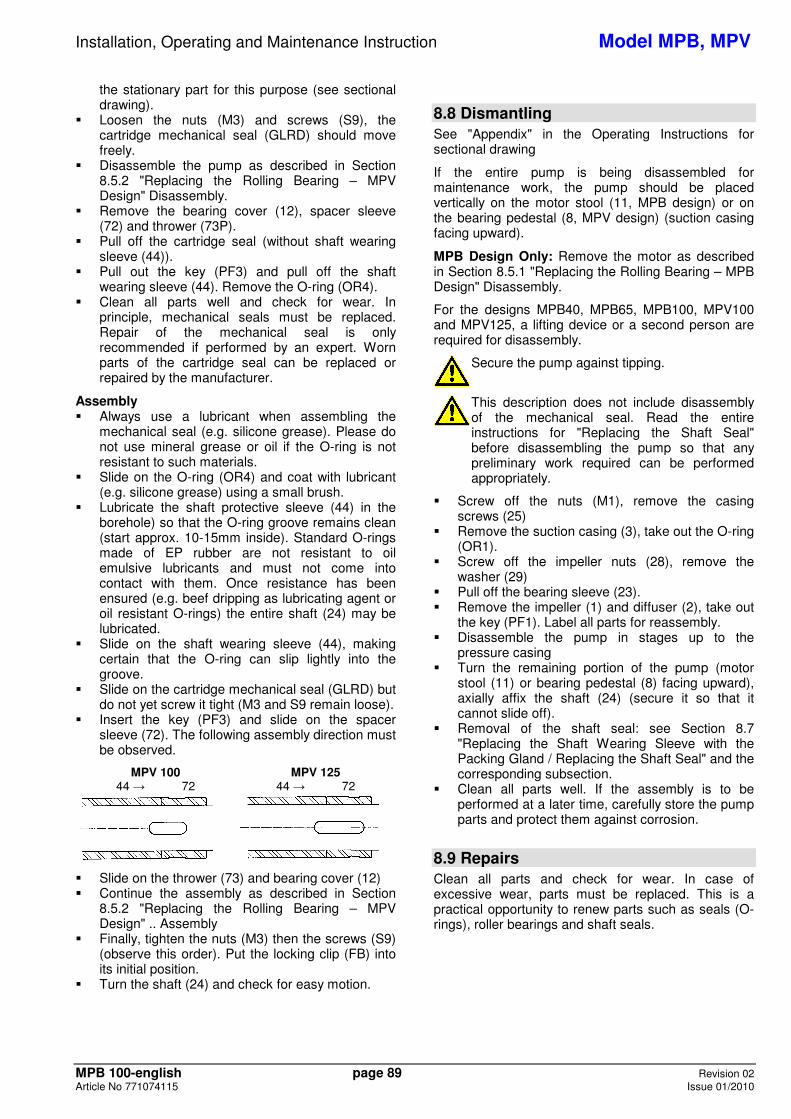
Installation, Operating and Maintenance Instruction Model MPB, MPV
MPB 100-english page 89 Revision 02 Article No 771074115 Issue 01/2010
the stationary part for this purpose (see sectional drawing).
� Loosen the nuts (M3) and screws (S9), the cartridge mechanical seal (GLRD) should move freely.
� Disassemble the pump as described in Section 8.5.2 "Replacing the Rolling Bearing – MPV Design" Disassembly.
� Remove the bearing cover (12), spacer sleeve (72) and thrower (73P).
� Pull off the cartridge seal (without shaft wearing sleeve (44)).
� Pull out the key (PF3) and pull off the shaft wearing sleeve (44). Remove the O-ring (OR4).
� Clean all parts well and check for wear. In principle, mechanical seals must be replaced. Repair of the mechanical seal is only recommended if performed by an expert. Worn parts of the cartridge seal can be replaced or repaired by the manufacturer.
Assembly � Always use a lubricant when assembling the
mechanical seal (e.g. silicone grease). Please do not use mineral grease or oil if the O-ring is not resistant to such materials.
� Slide on the O-ring (OR4) and coat with lubricant (e.g. silicone grease) using a small brush.
� Lubricate the shaft protective sleeve (44) in the borehole) so that the O-ring groove remains clean (start approx. 10-15mm inside). Standard O-rings made of EP rubber are not resistant to oil emulsive lubricants and must not come into contact with them. Once resistance has been ensured (e.g. beef dripping as lubricating agent or oil resistant O-rings) the entire shaft (24) may be lubricated.
� Slide on the shaft wearing sleeve (44), making certain that the O-ring can slip lightly into the groove.
� Slide on the cartridge mechanical seal (GLRD) but do not yet screw it tight (M3 and S9 remain loose).
� Insert the key (PF3) and slide on the spacer sleeve (72). The following assembly direction must be observed.
MPV 100 MPV 125 44 � 72 44 � 72
� Slide on the thrower (73) and bearing cover (12) � Continue the assembly as described in Section
8.5.2 "Replacing the Rolling Bearing – MPV Design" .. Assembly
� Finally, tighten the nuts (M3) then the screws (S9) (observe this order). Put the locking clip (FB) into its initial position.
� Turn the shaft (24) and check for easy motion.
8.8 Dismantling See "Appendix" in the Operating Instructions for sectional drawing
If the entire pump is being disassembled for maintenance work, the pump should be placed vertically on the motor stool (11, MPB design) or on the bearing pedestal (8, MPV design) (suction casing facing upward).
MPB Design Only: Remove the motor as described in Section 8.5.1 "Replacing the Rolling Bearing – MPB Design" Disassembly.
For the designs MPB40, MPB65, MPB100, MPV100 and MPV125, a lifting device or a second person are required for disassembly.
Secure the pump against tipping.
This description does not include disassembly of the mechanical seal. Read the entire instructions for "Replacing the Shaft Seal" before disassembling the pump so that any preliminary work required can be performed appropriately.
� Screw off the nuts (M1), remove the casing screws (25)
� Remove the suction casing (3), take out the O-ring (OR1).
� Screw off the impeller nuts (28), remove the washer (29)
� Pull off the bearing sleeve (23). � Remove the impeller (1) and diffuser (2), take out
the key (PF1). Label all parts for reassembly. � Disassemble the pump in stages up to the
pressure casing � Turn the remaining portion of the pump (motor
stool (11) or bearing pedestal (8) facing upward), axially affix the shaft (24) (secure it so that it cannot slide off).
� Removal of the shaft seal: see Section 8.7 "Replacing the Shaft Wearing Sleeve with the Packing Gland / Replacing the Shaft Seal" and the corresponding subsection.
� Clean all parts well. If the assembly is to be performed at a later time, carefully store the pump parts and protect them against corrosion.
8.9 Repairs Clean all parts and check for wear. In case of excessive wear, parts must be replaced. This is a practical opportunity to renew parts such as seals (O-rings), roller bearings and shaft seals.
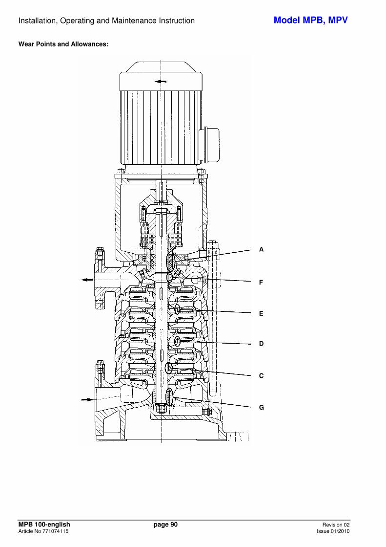
Installation, Operating and Maintenance Instruction Model MPB, MPV
MPB 100-english page 90 Revision 02 Article No 771074115 Issue 01/2010
Wear Points and Allowances:
A
F
E
D
C
G
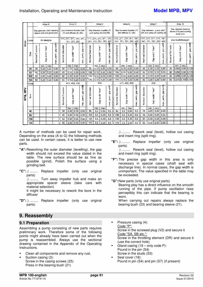
Installation, Operating and Maintenance Instruction Model MPB, MPV
MPB 100-english page 91 Revision 02 Article No 771074115 Issue 01/2010
A number of methods can be used for repair work. Depending on the area (A to G) the following methods can be used. In certain cases, it is better to use new parts.
"A": Reworking the outer diameter (levelling), the gap width should not exceed the value stated in the table. The new surface should be as fine as possible (grind). Polish the surface using a grinding belt.
"C": .) ......... Replace impeller (only use original parts) .) ......... Turn away impeller hub and make an appropriate spacer sleeve (take care with material selection) It might be necessary to rework the bore in the diffuser
"D": .) ......... Replace impeller (only use original parts)
.) ......... Rework seal (level), hollow out casing and insert ring (split ring).
"E": .) ......... Replace impeller (only use original parts) .) ......... Rework seal (level), hollow out casing and insert ring (split ring).
"F": The precise gap width in this area is only necessary in special cases (shaft seal with discharge line). In normal cases, the gap width is unimportant. The value specified in the table may be exceeded.
"G": New parts (only use original parts) Bearing play has a direct influence on the smooth running of the pipe. If pump oscillation rises perceptibly this can indicate that the bearing is worn. When carrying out repairs always replace the bearing bush (23) and bearing sleeve (21).
9. Reassembly
9.1 Preparation Assembling a pump consisting of new parts requires preliminary work. Therefore some of the following points might already have been carried out when the pump is reassembled. Always use the sectional drawing contained in the Appendix of the Operating Instructions.
� Clean all components and remove any rust. � Suction casing (3):
Screw in the casing screws (25) Press in the bearing bush (21)
� Pressure casing (4): Code "P": Screw in the screwed plug (V2) and secure it Code "SA, SB etc.": Screw in the throttling element (DR) and secure it (use the correct hole)
� Gland casing (19 – only code P): Pound in the pin (S4) Screw in the studs (S3)
� Seal cover (18): Pound in pin (S4) and pin (S7) (if present)
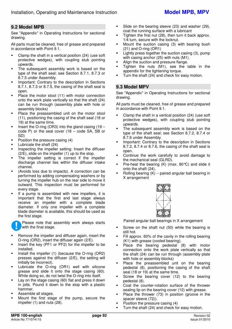
Installation, Operating and Maintenance Instruction Model MPB, MPV
MPB 100-english page 92 Revision 02 Article No 771074115 Issue 01/2010
9.2 Model MPB See "Appendix" in Operating Instructions for sectional drawing.
All parts must be cleaned, free of grease and prepared in accordance with Point 9.1.
� Clamp the shaft in a vertical position (24) (use soft protective wedges), with coupling stub pointing upwards.
� The subsequent assembly work is based on the type of the shaft seal; see Section 8.7.1, 8.7.3 or 8.7.5 under Assembly.
� Important: Contrary to the description in Sections 8.7.1, 8.7.3 or 8.7.5, the casing of the shaft seal is open.
� Place the motor stool (11) with motor connection onto the work plate vertically so that the shaft (24) can be run through (assembly plate with hole or assembly blocks)
� Place the preassembled unit on the motor stool (11), positioning the casing of the shaft seal (18 or 19) at the same time.
� Insert the O-ring (OR3) into the gland casing (19 – code P) or the seal cover (18 – code SA, SB or SD)
� Position the pressure casing (4) � Lubricate the shaft (24) � Inspecting the impeller setting: Insert the diffuser
(2/E), slide on the impeller (1) up to the stop. � The impeller setting is correct if the impeller
discharge channel lies within the diffuser intake channel.
� (Avoids loss due to impacts). A correction can be performed by adding compensating washers or by turning the impeller hub on the rear side to move it outward. This inspection must be performed for every stage.
� If a pump is assembled with new impellers, it is important that the first and last stage always receive an impeller with a complete blade diameter. If only one impeller with a complete blade diameter is available, this should be used as the first stage.
Please note that assembly work always starts with the final stage.
� Remove the impeller and diffuser again, insert the O-ring (OR2), insert the diffuser again (2/E).
� Insert the key (PF1 or PF2) for the impeller to be installed.
� Install the impeller (1) (because the O-ring (OR2) presses against the diffuser (2/E), the setting will initially be incorrect).
� Lubricate the O-ring (OR1) well with silicone grease and slide it onto the stage casing (60). While doing so, do not twist the O-ring into itself.
� Lay on the stage casing (60) flat and press it down in jolts. Pound it down to the stop with a plastic hammer.
� Assemble all stages. � Mount the first stage of the pump, secure the
impeller (1) and nuts (28).
� Slide on the bearing sleeve (23) and washer (29), coat the running surface with a lubricant
� Tighten the first nut (28), then turn it back approx. 1/4 turn, secure with the locknut.
� Mount the suction casing (3) with bearing bush (21) and O-ring (OR1)
� Lightly press together the suction casing (3), pump with casing anchor (25) with nuts (M1).
� Align the suction and pressure flange. � Tighten the nuts (M1), see the table in the
appendix for the tightening torque. � Turn the shaft (24) and check for easy motion.
9.3 Model MPV See "Appendix" in Operating Instructions for sectional drawing.
All parts must be cleaned, free of grease and prepared in accordance with Point 9.1.
� Clamp the shaft in a vertical position (24) (use soft protective wedges), with coupling stub pointing upwards.
� The subsequent assembly work is based on the type of the shaft seal; see Section 8.7.2, 8.7.4 or 8.7.6 under Assembly.
� Important: Contrary to the description in Sections 8.7.2, 8.7.4 or 8.7.6, the casing of the shaft seal is open.
� Continue the work carefully to avoid damage to the mechanical seal (GLRD).
� Pre-heat the bearing (K) (max. 80°C) and slide it onto the shaft (24).
� Rolling bearing (K) – paired angular ball bearing in X arrangement
Paired angular ball bearings in X arrangement
� Screw on the shaft nut (50) while the bearing is still hot.
� Fill approx. 60% of the cavity in the rolling bearing (K1) with grease (cooled bearing).
� Place the bearing pedestal (8) with motor connection onto the work plate vertically so that the shaft (24) can be run through (assembly plate with hole or assembly blocks)
� Place the preassembled unit on the bearing pedestal (8), positioning the casing of the shaft seal (18 or 19) at the same time.
� Screw the bearing cover (12) to the bearing pedestal (8).
� Coat the counter-rotation surface of the thrower sealing lip on the bearing cover (12) with grease.
� Place the thrower (73) in position (groove in the spacer sleeve (72)).
� Position the pressure casing (4) � Turn the shaft (24) and check for easy motion.
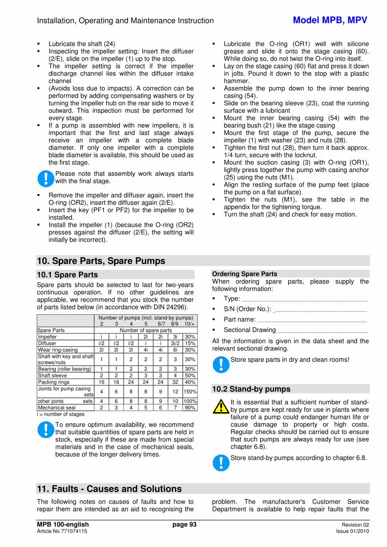
Installation, Operating and Maintenance Instruction Model MPB, MPV
MPB 100-english page 93 Revision 02 Article No 771074115 Issue 01/2010
� Lubricate the shaft (24) � Inspecting the impeller setting: Insert the diffuser
(2/E), slide on the impeller (1) up to the stop. � The impeller setting is correct if the impeller
discharge channel lies within the diffuser intake channel
� (Avoids loss due to impacts). A correction can be performed by adding compensating washers or by turning the impeller hub on the rear side to move it outward. This inspection must be performed for every stage.
� If a pump is assembled with new impellers, it is important that the first and last stage always receive an impeller with a complete blade diameter. If only one impeller with a complete blade diameter is available, this should be used as the first stage.
Please note that assembly work always starts with the final stage.
� Remove the impeller and diffuser again, insert the O-ring (OR2), insert the diffuser again (2/E).
� Insert the key (PF1 or PF2) for the impeller to be installed.
� Install the impeller (1) (because the O-ring (OR2) presses against the diffuser (2/E), the setting will initially be incorrect).
� Lubricate the O-ring (OR1) well with silicone grease and slide it onto the stage casing (60). While doing so, do not twist the O-ring into itself.
� Lay on the stage casing (60) flat and press it down in jolts. Pound it down to the stop with a plastic hammer.
� Assemble the pump down to the inner bearing casing (54).
� Slide on the bearing sleeve (23), coat the running surface with a lubricant
� Mount the inner bearing casing (54) with the bearing bush (21) like the stage casing
� Mount the first stage of the pump, secure the impeller (1) with washer (23) and nuts (28).
� Tighten the first nut (28), then turn it back approx. 1/4 turn, secure with the locknut.
� Mount the suction casing (3) with O-ring (OR1), lightly press together the pump with casing anchor (25) using the nuts (M1).
� Align the resting surface of the pump feet (place the pump on a flat surface).
� Tighten the nuts (M1), see the table in the appendix for the tightening torque.
� Turn the shaft (24) and check for easy motion.
10. Spare Parts, Spare Pumps
10.1 Spare Parts Spare parts should be selected to last for two-years continuous operation. If no other guidelines are applicable, we recommend that you stock the number of parts listed below (in accordance with DIN 24296).
Number of pumps (incl. stand-by pumps) 2 3 4 5 6/7 8/9 10/+
Spare Parts Number of spare parts Impeller i i i 2i 2i 3i 30% Diffuser i/2 i/2 i/2 i i 3i/2 15% Wear ring-casing 2i 2i 2i 4i 4i 6i 30% Shaft with key and shaft screws/nuts
1 1 2 2 2 3 30%
Bearing (roller bearing) 1 1 2 2 2 3 30% Shaft sleeve 2 2 2 3 3 4 50% Packing rings 16 16 24 24 24 32 40% Joints for pump casing sets
4 6 8 8 9 12 150%
other joints sets 4 6 8 8 9 10 100% Mechanical seal 2 3 4 5 6 7 90% i = number of stages
To ensure optimum availability, we recommend that suitable quantities of spare parts are held in stock, especially if these are made from special materials and in the case of mechanical seals, because of the longer delivery times.
Ordering Spare Parts When ordering spare parts, please supply the following information:
� Type: ______________________________________________________________________
� S/N (Order No.): ____________________________________________________
� Part name: _____________________________________________________________
� Sectional Drawing __________________________________________________
All the information is given in the data sheet and the relevant sectional drawing.
Store spare parts in dry and clean rooms!
10.2 Stand-by pumps
It is essential that a sufficient number of stand-by pumps are kept ready for use in plants where failure of a pump could endanger human life or cause damage to property or high costs. Regular checks should be carried out to ensure that such pumps are always ready for use (see chapter 6.8).
Store stand-by pumps according to chapter 6.8.
11. Faults - Causes and Solutions The following notes on causes of faults and how to repair them are intended as an aid to recognising the
problem. The manufacturer's Customer Service Department is available to help repair faults that the
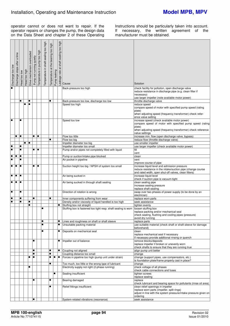
Installation, Operating and Maintenance Instruction Model MPB, MPV
MPB 100-english page 94 Revision 02 Article No 771074115 Issue 01/2010
operator cannot or does not want to repair. If the operator repairs or changes the pump, the design data on the Data Sheet and chapter 2 of these Operating
Instructions should be particularly taken into account. If necessary, the written agreement of the manufacturer must be obtained.
Dis
char
ge to
o lo
w
Dis
char
ge s
tops
afte
r a
time
Hea
d to
o lo
w
Hea
d to
o hi
gh
Driv
e m
echa
nism
ove
rload
ed
Pum
p no
t run
ning
qui
etly
Tem
pera
ture
in p
ump
too
high
Tem
pera
ture
in s
haft
seal
ing
too
high
Tem
pera
ture
at t
he b
earin
g to
o hi
gh
Pum
p le
akin
g
Leak
age
rate
at s
haft
seal
ing
too
high
Cause
Solution
� Back-pressure too high
check facility for pollution, open discharge valve reduce resistance in discharge pipe (e.g. clean filter if necessary) use larger impeller (note available motor power)
� � � Back-pressure too low, discharge too low throttle discharge valve � � Speed too high reduce speed
compare speed of motor with specified pump speed (rating plate) when adjusting speed (frequency transformer) check refer- ence value setting
� � Speed too low increase speed (check available motor power) compare speed of motor with specified pump speed (rating plate) when adjusting speed (frequency transformer) check reference value settings
� � � � Flow too little increase min. flow (open discharge valve, bypass) � Flow too big reduce flow (throttle discharge valve) � � Impeller diameter too big use smaller impeller � � Impeller diameter too small use larger impeller (check available motor power) � � � � Pump and/or pipes not completely filled with liquid fill
vent � � � Pump or suction/intake pipe blocked clean � � Air pocket in pipeline vent
improve course of pipe � � � � � Suction height too big / NPSH of system too small
increase liquid level and admission pressure reduce resistance in the intake/suction pipe (change course and rated width, open shut-off valves, clean filters)
� � � Air being sucked in increase liquid level check if suction pipe is vacuum-tight
� � � Air being sucked in through shaft sealing clean sealing pipe increase sealing pressure replace shaft sealing
� � Direction of rotation is wrong swap over two phases of power supply (to be done by an electrician)
� � � � Inner components suffering from wear replace worn parts � � � Density and/or viscosity of liquid handled is too high seek assistance � � Stuffing box not straight tighten evenly � Stuffing box is fastened too tight resp. shaft sealing is worn loosen stuffing box
replace packing and/or mechanical seal check sealing, flushing and cooling pipes (pressure) avoid dry running
� � Lines and roughness on shaft or shaft sleeve replace parts � � Unsuitable packing material use suitable material (check shaft or shaft sleeve for damage
beforehand) � � Deposits on mechanical seal
clean replace mechanical seal if necessary if necessary provide additional rinsing or quench
� � Impeller out of balance
remove blocks/deposits replace impeller if broken or unevenly worn check shafts to ensure that they are running true
� � � Coupling not aligned align pump unit better � � Coupling distance too small change � � � � � Forces in pipeline too high (pump unit under strain) change (support pipes, use compensators, etc.)
is foundation plate/frame properly cast in place? � Too much, too little or the wrong type of lubricant change � Electricity supply not right (2-phase running) check voltage of all phases
check cable connections and fuses � Sealing insufficient tighten screws
replace sealing � � Bearing damaged replace
check lubricant and bearing space for pollutants (rinse oil area) � Relief fittings insufficient
clean relief openings in impeller replace worn parts (impeller, split rings) adjust in line with the system pressure/intake pressure given on ordering
� System-related vibrations (resonance) seek assistance
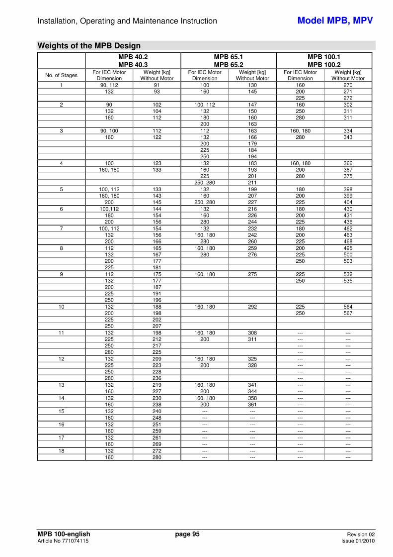
Installation, Operating and Maintenance Instruction Model MPB, MPV
MPB 100-english page 95 Revision 02 Article No 771074115 Issue 01/2010
Weights of the MPB Design
MPB 40.2 MPB 40.3
MPB 65.1 MPB 65.2
MPB 100.1 MPB 100.2
No. of Stages For IEC Motor Dimension
Weight [kg] Without Motor
For IEC Motor Dimension
Weight [kg] Without Motor
For IEC Motor Dimension
Weight [kg] Without Motor
1 90, 112 91 100 130 160 270 132 93 160 145 200 271 225 272 2 90 102 100, 112 147 160 302 132 104 132 150 250 311 160 112 180 160 280 311 200 163 3 90, 100 112 112 163 160, 180 334 160 122 132 166 280 343 200 179 225 184 250 194 4 100 123 132 183 160, 180 366 160, 180 133 160 193 200 367 225 201 280 375 250, 280 211 5 100, 112 133 132 199 180 398 160, 180 143 160 207 200 399 200 145 250, 280 227 225 404 6 100,112 144 132 216 180 430 180 154 160 226 200 431 200 156 280 244 225 436 7 100, 112 154 132 232 180 462 132 156 160, 180 242 200 463 200 166 280 260 225 468 8 112 165 160, 180 259 200 495 132 167 280 276 225 500 200 177 250 503 225 181 9 112 175 160, 180 275 225 532 132 177 250 535 200 187 225 191 250 196
10 132 188 160, 180 292 225 564 200 198 250 567 225 202 250 207
11 132 198 160, 180 308 --- --- 225 212 200 311 --- --- 250 217 --- --- 280 225 --- ---
12 132 209 160, 180 325 --- --- 225 223 200 328 --- --- 250 228 --- --- 280 236 --- ---
13 132 219 160, 180 341 --- --- 160 227 200 344 --- ---
14 132 230 160, 180 358 --- --- 160 238 200 361 --- ---
15 132 240 --- --- --- --- 160 248 --- --- --- ---
16 132 251 --- --- --- --- 160 259 --- --- --- ---
17 132 261 --- --- --- --- 160 269 --- --- --- ---
18 132 272 --- --- --- --- 160 280 --- --- --- ---
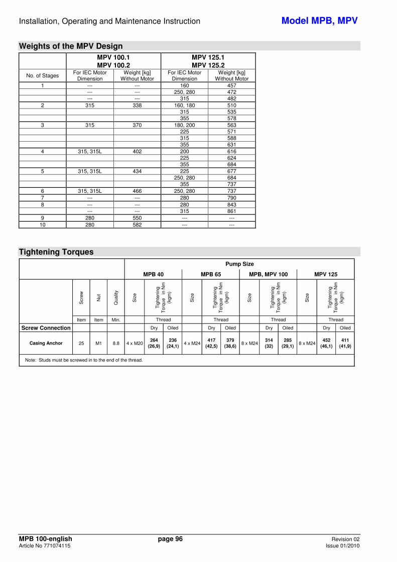
Installation, Operating and Maintenance Instruction Model MPB, MPV
MPB 100-english page 96 Revision 02 Article No 771074115 Issue 01/2010
Weights of the MPV Design
MPV 100.1 MPV 100.2
MPV 125.1 MPV 125.2
No. of Stages For IEC Motor Dimension
Weight [kg] Without Motor
For IEC Motor Dimension
Weight [kg] Without Motor
1 --- --- 160 457 --- --- 250, 280 472 --- --- 315 482 2 315 338 160, 180 510 315 535 355 578 3 315 370 180, 200 563 225 571 315 588 355 631 4 315, 315L 402 200 616 225 624 355 684 5 315, 315L 434 225 677 250, 280 684 355 737 6 315, 315L 466 250, 280 737 7 --- --- 280 790 8 --- --- 280 843 --- --- 315 861 9 280 550 --- ---
10 280 582 --- ---
Tightening Torques
Scr
ew
Nu
t
Qua
lity
Siz
e
Siz
e
Siz
e
Siz
e
Item Item Min.
Screw Connection Dry Oiled Dry Oiled Dry Oiled Dry Oiled
Casing Anchor 25 M1 8.8 4 x M20264
(26,9)236
(24,1)4 x M24
417 (42,5)
379 (38,6)
8 x M24314 (32)
285 (29,1)
8 x M24452
(46,1)411
(41,9)
Pump Size
Thread
MPV 125
Tig
hten
ing
To
rqu
e i
n N
m
(kgm
)
Thread
Tig
hten
ing
To
rqu
e i
n N
m
(kgm
)
Note: Studs must be screwed in to the end of the thread.
MPB, MPV 100T
ight
enin
g T
orq
ue
in
Nm
(k
gm)
Thread
MPB 40 MPB 65
Tig
hten
ing
To
rqu
e i
n N
m
(kgm
)
Thread
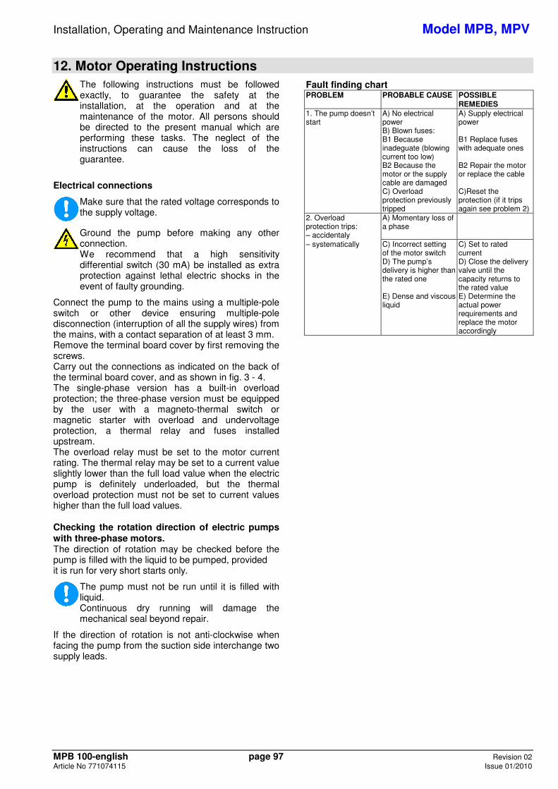
Installation, Operating and Maintenance Instruction Model MPB, MPV
MPB 100-english page 97 Revision 02 Article No 771074115 Issue 01/2010
12. Motor Operating Instructions
The following instructions must be followed exactly, to guarantee the safety at the installation, at the operation and at the maintenance of the motor. All persons should be directed to the present manual which are performing these tasks. The neglect of the instructions can cause the loss of the guarantee.
Electrical connections
Make sure that the rated voltage corresponds to the supply voltage.
Ground the pump before making any other connection. We recommend that a high sensitivity differential switch (30 mA) be installed as extra protection against lethal electric shocks in the event of faulty grounding.
Connect the pump to the mains using a multiple-pole switch or other device ensuring multiple-pole disconnection (interruption of all the supply wires) from the mains, with a contact separation of at least 3 mm. Remove the terminal board cover by first removing the screws. Carry out the connections as indicated on the back of the terminal board cover, and as shown in fig. 3 - 4. The single-phase version has a built-in overload protection; the three-phase version must be equipped by the user with a magneto-thermal switch or magnetic starter with overload and undervoltage protection, a thermal relay and fuses installed upstream. The overload relay must be set to the motor current rating. The thermal relay may be set to a current value slightly lower than the full load value when the electric pump is definitely underloaded, but the thermal overload protection must not be set to current values higher than the full load values. Checking the rotation direction of electric pumps with three-phase motors. The direction of rotation may be checked before the pump is filled with the liquid to be pumped, provided it is run for very short starts only.
The pump must not be run until it is filled with liquid. Continuous dry running will damage the mechanical seal beyond repair.
If the direction of rotation is not anti-clockwise when facing the pump from the suction side interchange two supply leads.
Fault finding chart PROBLEM PROBABLE CAUSE POSSIBLE
REMEDIES 1. The pump doesn’t start
A) No electrical power B) Blown fuses: B1 Because inadeguate (blowing current too low) B2 Because the motor or the supply cable are damaged C) Overload protection previously tripped
A) Supply electrical power B1 Replace fuses with adequate ones B2 Repair the motor or replace the cable C)Reset the protection (if it trips again see problem 2)
2. Overload protection trips: – accidentaly
A) Momentary loss of a phase
– systematically C) Incorrect setting of the motor switch D) The pump’s delivery is higher than the rated one E) Dense and viscous liquid
C) Set to rated current D) Close the delivery valve until the capacity returns to the rated value E) Determine the actual power requirements and replace the motor accordingly
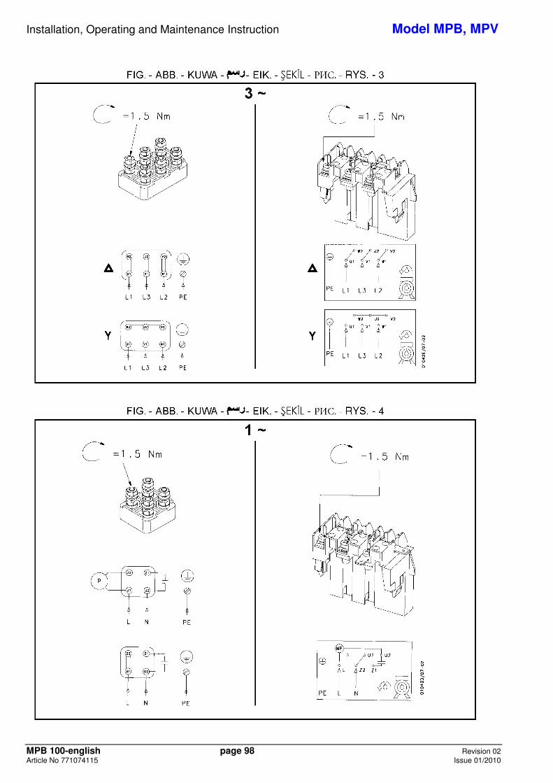
Installation, Operating and Maintenance Instruction Model MPB, MPV
MPB 100-english page 98 Revision 02 Article No 771074115 Issue 01/2010
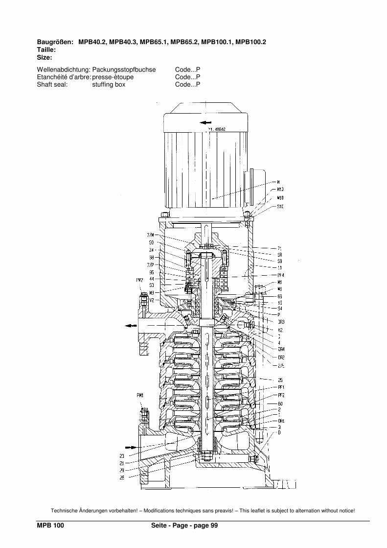
MPB 100 Seite - Page - page 99
Baugrößen: MPB40.2, MPB40.3, MPB65.1, MPB65.2, MPB100.1, MPB100.2 Taille: Size:
Wellenabdichtung: Packungsstopfbuchse Code...P Etanchéité d’arbre: presse-ètoupe Code...P Shaft seal: stuffing box Code...P
Technische Änderungen vorbehalten! – Modifications techniques sans preavis! – This leaflet is subject to alternation without notice!
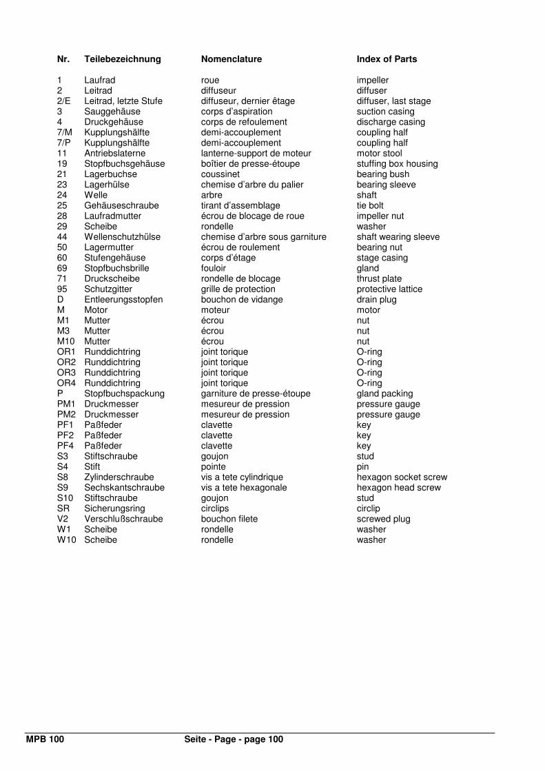
MPB 100 Seite - Page - page 100
Nr. Teilebezeichnung Nomenclature Index of Parts
1 Laufrad roue impeller 2 Leitrad diffuseur diffuser 2/E Leitrad, letzte Stufe diffuseur, dernier êtage diffuser, last stage 3 Sauggehäuse corps d’aspiration suction casing 4 Druckgehäuse corps de refoulement discharge casing 7/M Kupplungshälfte demi-accouplement coupling half 7/P Kupplungshälfte demi-accouplement coupling half 11 Antriebslaterne lanterne-support de moteur motor stool 19 Stopfbuchsgehäuse boîtier de presse-étoupe stuffing box housing 21 Lagerbuchse coussinet bearing bush 23 Lagerhülse chemise d’arbre du palier bearing sleeve 24 Welle arbre shaft 25 Gehäuseschraube tirant d’assemblage tie bolt 28 Laufradmutter écrou de blocage de roue impeller nut 29 Scheibe rondelle washer 44 Wellenschutzhülse chemise d’arbre sous garniture shaft wearing sleeve 50 Lagermutter écrou de roulement bearing nut 60 Stufengehäuse corps d’étage stage casing 69 Stopfbuchsbrille fouloir gland 71 Druckscheibe rondelle de blocage thrust plate 95 Schutzgitter grille de protection protective lattice D Entleerungsstopfen bouchon de vidange drain plug M Motor moteur motor M1 Mutter écrou nut M3 Mutter écrou nut M10 Mutter écrou nut OR1 Runddichtring joint torique O-ring OR2 Runddichtring joint torique O-ring OR3 Runddichtring joint torique O-ring OR4 Runddichtring joint torique O-ring P Stopfbuchspackung garniture de presse-étoupe gland packing PM1 Druckmesser mesureur de pression pressure gauge PM2 Druckmesser mesureur de pression pressure gauge PF1 Paßfeder clavette key PF2 Paßfeder clavette key PF4 Paßfeder clavette key S3 Stiftschraube goujon stud S4 Stift pointe pin S8 Zylinderschraube vis a tete cylindrique hexagon socket screw S9 Sechskantschraube vis a tete hexagonale hexagon head screw S10 Stiftschraube goujon stud SR Sicherungsring circlips circlip V2 Verschlußschraube bouchon filete screwed plug W1 Scheibe rondelle washer W10 Scheibe rondelle washer

MPB 100 Seite - Page - page 101
Baugrößen: MPB40.2, MPB40.3, MPB65.1, MPB65.2, MPB100.1, MPB100.2 Taille: Size:
Wellenabdichtung: Gleitringdichtung Code...SA Etanchéité d’arbre: garniture mécanique Code...SA Shaft seal: mechanical seal Code...SA
Technische Änderungen vorbehalten! – Modifications techniques sans preavis! – This leaflet is subject to alternation without notice!
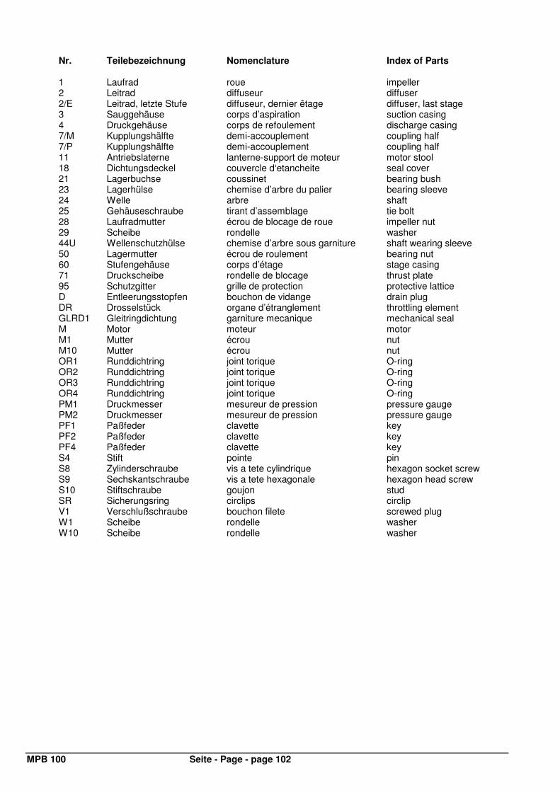
MPB 100 Seite - Page - page 102
Nr. Teilebezeichnung Nomenclature Index of Parts
1 Laufrad roue impeller 2 Leitrad diffuseur diffuser 2/E Leitrad, letzte Stufe diffuseur, dernier êtage diffuser, last stage 3 Sauggehäuse corps d’aspiration suction casing 4 Druckgehäuse corps de refoulement discharge casing 7/M Kupplungshälfte demi-accouplement coupling half 7/P Kupplungshälfte demi-accouplement coupling half 11 Antriebslaterne lanterne-support de moteur motor stool 18 Dichtungsdeckel couvercle d‘etancheite seal cover 21 Lagerbuchse coussinet bearing bush 23 Lagerhülse chemise d’arbre du palier bearing sleeve 24 Welle arbre shaft 25 Gehäuseschraube tirant d’assemblage tie bolt 28 Laufradmutter écrou de blocage de roue impeller nut 29 Scheibe rondelle washer 44U Wellenschutzhülse chemise d’arbre sous garniture shaft wearing sleeve 50 Lagermutter écrou de roulement bearing nut 60 Stufengehäuse corps d’étage stage casing 71 Druckscheibe rondelle de blocage thrust plate 95 Schutzgitter grille de protection protective lattice D Entleerungsstopfen bouchon de vidange drain plug DR Drosselstück organe d’étranglement throttling element GLRD1 Gleitringdichtung garniture mecanique mechanical seal M Motor moteur motor M1 Mutter écrou nut M10 Mutter écrou nut OR1 Runddichtring joint torique O-ring OR2 Runddichtring joint torique O-ring OR3 Runddichtring joint torique O-ring OR4 Runddichtring joint torique O-ring PM1 Druckmesser mesureur de pression pressure gauge PM2 Druckmesser mesureur de pression pressure gauge PF1 Paßfeder clavette key PF2 Paßfeder clavette key PF4 Paßfeder clavette key S4 Stift pointe pin S8 Zylinderschraube vis a tete cylindrique hexagon socket screw S9 Sechskantschraube vis a tete hexagonale hexagon head screw S10 Stiftschraube goujon stud SR Sicherungsring circlips circlip V1 Verschlußschraube bouchon filete screwed plug W1 Scheibe rondelle washer W10 Scheibe rondelle washer
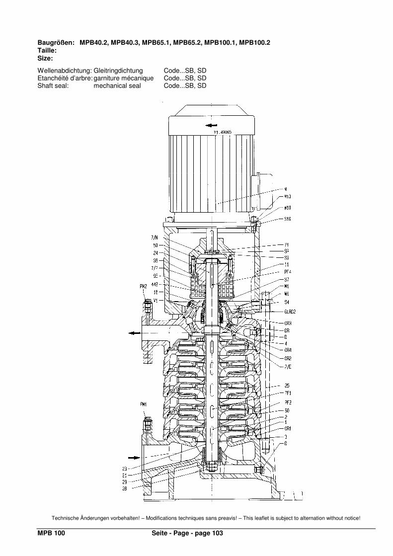
MPB 100 Seite - Page - page 103
Baugrößen: MPB40.2, MPB40.3, MPB65.1, MPB65.2, MPB100.1, MPB100.2 Taille: Size:
Wellenabdichtung: Gleitringdichtung Code...SB, SD Etanchéité d’arbre: garniture mécanique Code...SB, SD Shaft seal: mechanical seal Code...SB, SD
Technische Änderungen vorbehalten! – Modifications techniques sans preavis! – This leaflet is subject to alternation without notice!

MPB 100 Seite - Page - page 104
Nr. Teilebezeichnung Nomenclature Index of Parts
1 Laufrad roue impeller 2 Leitrad diffuseur diffuser 2/E Leitrad, letzte Stufe diffuseur, dernier êtage diffuser, last stage 3 Sauggehäuse corps d’aspiration suction casing 4 Druckgehäuse corps de refoulement discharge casing 7/M Kupplungshälfte demi-accouplement coupling half 7/P Kupplungshälfte demi-accouplement coupling half 11 Antriebslaterne lanterne-support de moteur motor stool 18 Dichtungsdeckel couvercle d‘etancheite seal cover 21 Lagerbuchse coussinet bearing bush 23 Lagerhülse chemise d’arbre du palier bearing sleeve 24 Welle arbre shaft 25 Gehäuseschraube tirant d’assemblage tie bolt 28 Laufradmutter écrou de blocage de roue impeller nut 29 Scheibe rondelle washer 44B Wellenschutzhülse chemise d’arbre sous garniture shaft wearing sleeve 50 Lagermutter écrou de roulement bearing nut 60 Stufengehäuse corps d’étage stage casing 71 Druckscheibe rondelle de blocage thrust plate 95 Schutzgitter grille de protection protective lattice D Entleerungsstopfen bouchon de vidange drain plug DR Drosselstück organe d’étranglement throttling element GLRD2 Gleitringdichtung garniture mecanique mechanical seal M Motor moteur motor M1 Mutter écrou nut M10 Mutter écrou nut OR1 Runddichtring joint torique O-ring OR2 Runddichtring joint torique O-ring OR3 Runddichtring joint torique O-ring OR4 Runddichtring joint torique O-ring PM1 Druckmesser mesureur de pression pressure gauge PM2 Druckmesser mesureur de pression pressure gauge PF1 Paßfeder clavette key PF2 Paßfeder clavette key PF4 Paßfeder clavette key S4 Stift pointe pin S7 Stift pointe pin S8 Zylinderschraube vis a tete cylindrique hexagon socket screw S9 Sechskantschraube vis a tete hexagonale hexagon head screw S10 Stiftschraube goujon stud SR Sicherungsring circlips circlip V1 Verschlußschraube bouchon filete screwed plug W1 Scheibe rondelle washer W10 Scheibe rondelle washer
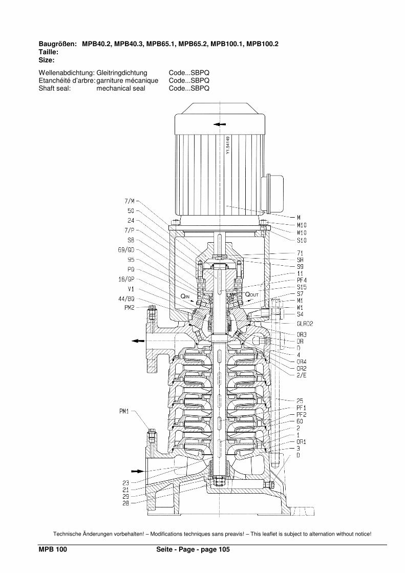
MPB 100 Seite - Page - page 105
Baugrößen: MPB40.2, MPB40.3, MPB65.1, MPB65.2, MPB100.1, MPB100.2 Taille: Size:
Wellenabdichtung: Gleitringdichtung Code...SBPQ Etanchéité d’arbre: garniture mécanique Code...SBPQ Shaft seal: mechanical seal Code...SBPQ
Technische Änderungen vorbehalten! – Modifications techniques sans preavis! – This leaflet is subject to alternation without notice!
QIN QOUT
Y1.
5414
9
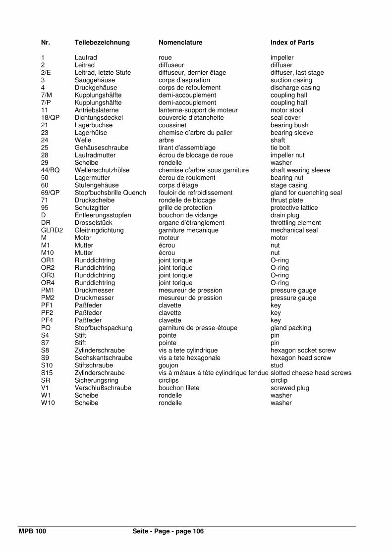
MPB 100 Seite - Page - page 106
Nr. Teilebezeichnung Nomenclature Index of Parts
1 Laufrad roue impeller 2 Leitrad diffuseur diffuser 2/E Leitrad, letzte Stufe diffuseur, dernier êtage diffuser, last stage 3 Sauggehäuse corps d’aspiration suction casing 4 Druckgehäuse corps de refoulement discharge casing 7/M Kupplungshälfte demi-accouplement coupling half 7/P Kupplungshälfte demi-accouplement coupling half 11 Antriebslaterne lanterne-support de moteur motor stool 18/QP Dichtungsdeckel couvercle d‘etancheite seal cover 21 Lagerbuchse coussinet bearing bush 23 Lagerhülse chemise d’arbre du palier bearing sleeve 24 Welle arbre shaft 25 Gehäuseschraube tirant d’assemblage tie bolt 28 Laufradmutter écrou de blocage de roue impeller nut 29 Scheibe rondelle washer 44/BQ Wellenschutzhülse chemise d’arbre sous garniture shaft wearing sleeve 50 Lagermutter écrou de roulement bearing nut 60 Stufengehäuse corps d’étage stage casing 69/QP Stopfbuchsbrille Quench fouloir de refroidissement gland for quenching seal 71 Druckscheibe rondelle de blocage thrust plate 95 Schutzgitter grille de protection protective lattice D Entleerungsstopfen bouchon de vidange drain plug DR Drosselstück organe d’étranglement throttling element GLRD2 Gleitringdichtung garniture mecanique mechanical seal M Motor moteur motor M1 Mutter écrou nut M10 Mutter écrou nut OR1 Runddichtring joint torique O-ring OR2 Runddichtring joint torique O-ring OR3 Runddichtring joint torique O-ring OR4 Runddichtring joint torique O-ring PM1 Druckmesser mesureur de pression pressure gauge PM2 Druckmesser mesureur de pression pressure gauge PF1 Paßfeder clavette key PF2 Paßfeder clavette key PF4 Paßfeder clavette key PQ Stopfbuchspackung garniture de presse-étoupe gland packing S4 Stift pointe pin S7 Stift pointe pin S8 Zylinderschraube vis a tete cylindrique hexagon socket screw S9 Sechskantschraube vis a tete hexagonale hexagon head screw S10 Stiftschraube goujon stud S15 Zylinderschraube vis à métaux à tête cylindrique fendue slotted cheese head screws SR Sicherungsring circlips circlip V1 Verschlußschraube bouchon filete screwed plug W1 Scheibe rondelle washer W10 Scheibe rondelle washer
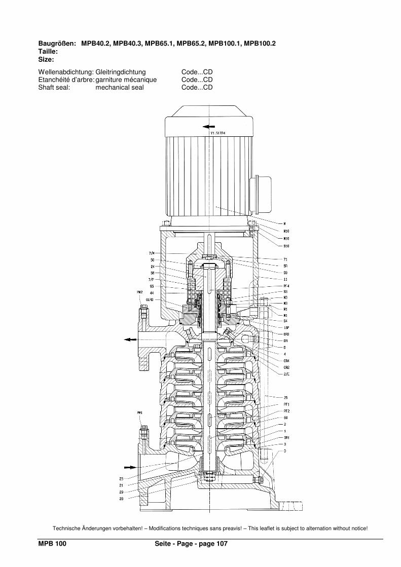
MPB 100 Seite - Page - page 107
Baugrößen: MPB40.2, MPB40.3, MPB65.1, MPB65.2, MPB100.1, MPB100.2 Taille: Size:
Wellenabdichtung: Gleitringdichtung Code...CD Etanchéité d’arbre: garniture mécanique Code...CD Shaft seal: mechanical seal Code...CD
Technische Änderungen vorbehalten! – Modifications techniques sans preavis! – This leaflet is subject to alternation without notice!
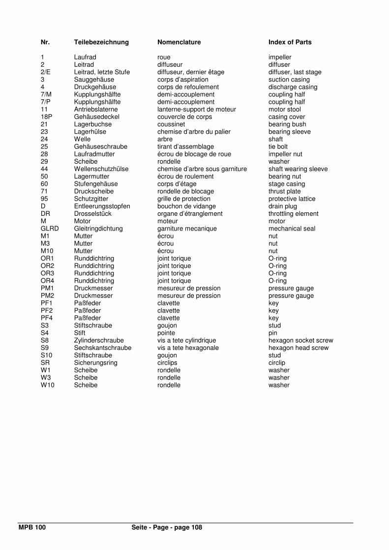
MPB 100 Seite - Page - page 108
Nr. Teilebezeichnung Nomenclature Index of Parts
1 Laufrad roue impeller 2 Leitrad diffuseur diffuser 2/E Leitrad, letzte Stufe diffuseur, dernier êtage diffuser, last stage 3 Sauggehäuse corps d’aspiration suction casing 4 Druckgehäuse corps de refoulement discharge casing 7/M Kupplungshälfte demi-accouplement coupling half 7/P Kupplungshälfte demi-accouplement coupling half 11 Antriebslaterne lanterne-support de moteur motor stool 18P Gehäusedeckel couvercle de corps casing cover 21 Lagerbuchse coussinet bearing bush 23 Lagerhülse chemise d’arbre du palier bearing sleeve 24 Welle arbre shaft 25 Gehäuseschraube tirant d’assemblage tie bolt 28 Laufradmutter écrou de blocage de roue impeller nut 29 Scheibe rondelle washer 44 Wellenschutzhülse chemise d’arbre sous garniture shaft wearing sleeve 50 Lagermutter écrou de roulement bearing nut 60 Stufengehäuse corps d’étage stage casing 71 Druckscheibe rondelle de blocage thrust plate 95 Schutzgitter grille de protection protective lattice D Entleerungsstopfen bouchon de vidange drain plug DR Drosselstück organe d’étranglement throttling element M Motor moteur motor GLRD Gleitringdichtung garniture mecanique mechanical seal M1 Mutter écrou nut M3 Mutter écrou nut M10 Mutter écrou nut OR1 Runddichtring joint torique O-ring OR2 Runddichtring joint torique O-ring OR3 Runddichtring joint torique O-ring OR4 Runddichtring joint torique O-ring PM1 Druckmesser mesureur de pression pressure gauge PM2 Druckmesser mesureur de pression pressure gauge PF1 Paßfeder clavette key PF2 Paßfeder clavette key PF4 Paßfeder clavette key S3 Stiftschraube goujon stud S4 Stift pointe pin S8 Zylinderschraube vis a tete cylindrique hexagon socket screw S9 Sechskantschraube vis a tete hexagonale hexagon head screw S10 Stiftschraube goujon stud SR Sicherungsring circlips circlip W1 Scheibe rondelle washer W3 Scheibe rondelle washer W10 Scheibe rondelle washer
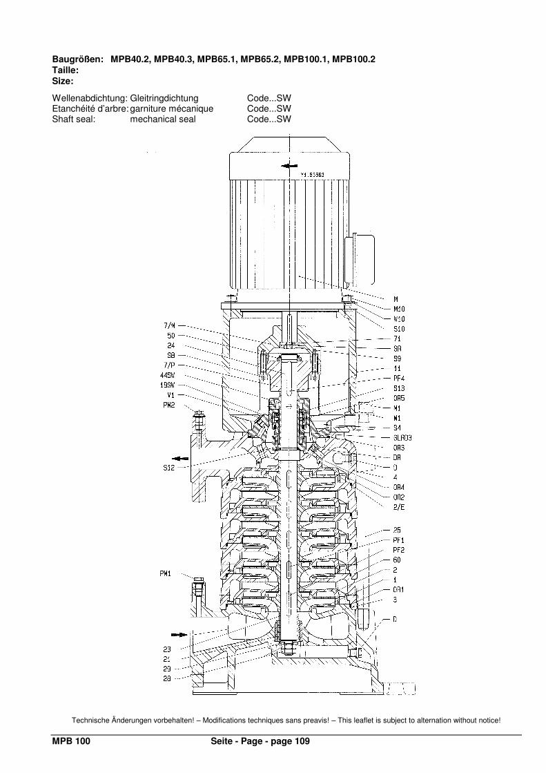
MPB 100 Seite - Page - page 109
Baugrößen: MPB40.2, MPB40.3, MPB65.1, MPB65.2, MPB100.1, MPB100.2 Taille: Size:
Wellenabdichtung: Gleitringdichtung Code...SW Etanchéité d’arbre: garniture mécanique Code...SW Shaft seal: mechanical seal Code...SW
Technische Änderungen vorbehalten! – Modifications techniques sans preavis! – This leaflet is subject to alternation without notice!
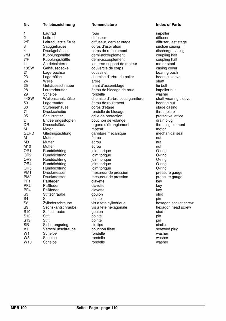
MPB 100 Seite - Page - page 110
Nr. Teilebezeichnung Nomenclature Index of Parts
1 Laufrad roue impeller 2 Leitrad diffuseur diffuser 2/E Leitrad, letzte Stufe diffuseur, dernier êtage diffuser, last stage 3 Sauggehäuse corps d’aspiration suction casing 4 Druckgehäuse corps de refoulement discharge casing 7/M Kupplungshälfte demi-accouplement coupling half 7/P Kupplungshälfte demi-accouplement coupling half 11 Antriebslaterne lanterne-support de moteur motor stool 18SW Gehäusedeckel couvercle de corps casing cover 21 Lagerbuchse coussinet bearing bush 23 Lagerhülse chemise d’arbre du palier bearing sleeve 24 Welle arbre shaft 25 Gehäuseschraube tirant d’assemblage tie bolt 28 Laufradmutter écrou de blocage de roue impeller nut 29 Scheibe rondelle washer 44SW Wellenschutzhülse chemise d’arbre sous garniture shaft wearing sleeve 50 Lagermutter écrou de roulement bearing nut 60 Stufengehäuse corps d’étage stage casing 71 Druckscheibe rondelle de blocage thrust plate 95 Schutzgitter grille de protection protective lattice D Entleerungsstopfen bouchon de vidange drain plug DR Drosselstück organe d’étranglement throttling element M Motor moteur motor GLRD Gleitringdichtung garniture mecanique mechanical seal M1 Mutter écrou nut M3 Mutter écrou nut M10 Mutter écrou nut OR1 Runddichtring joint torique O-ring OR2 Runddichtring joint torique O-ring OR3 Runddichtring joint torique O-ring OR4 Runddichtring joint torique O-ring OR5 Runddichtring joint torique O-ring PM1 Druckmesser mesureur de pression pressure gauge PM2 Druckmesser mesureur de pression pressure gauge PF1 Paßfeder clavette key PF2 Paßfeder clavette key PF4 Paßfeder clavette key S3 Stiftschraube goujon stud S4 Stift pointe pin S8 Zylinderschraube vis a tete cylindrique hexagon socket screw S9 Sechskantschraube vis a tete hexagonale hexagon head screw S10 Stiftschraube goujon stud S12 Stift pointe pin S13 Stift pointe pin SR Sicherungsring circlips circlip V1 Verschlußschraube bouchon filete screwed plug W1 Scheibe rondelle washer W3 Scheibe rondelle washer W10 Scheibe rondelle washer
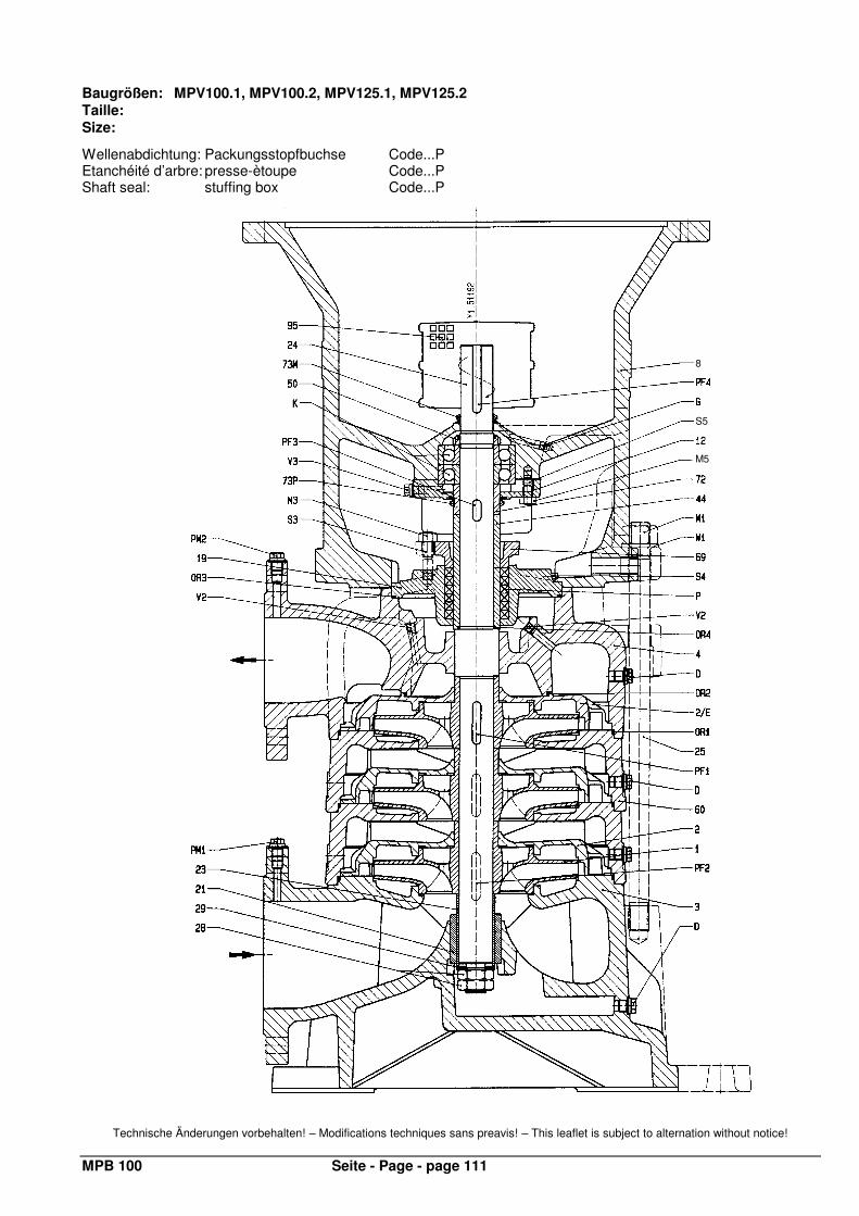
MPB 100 Seite - Page - page 111
Baugrößen: MPV100.1, MPV100.2, MPV125.1, MPV125.2 Taille: Size:
Wellenabdichtung: Packungsstopfbuchse Code...P Etanchéité d’arbre: presse-ètoupe Code...P Shaft seal: stuffing box Code...P
Technische Änderungen vorbehalten! – Modifications techniques sans preavis! – This leaflet is subject to alternation without notice!
8
S5
M5
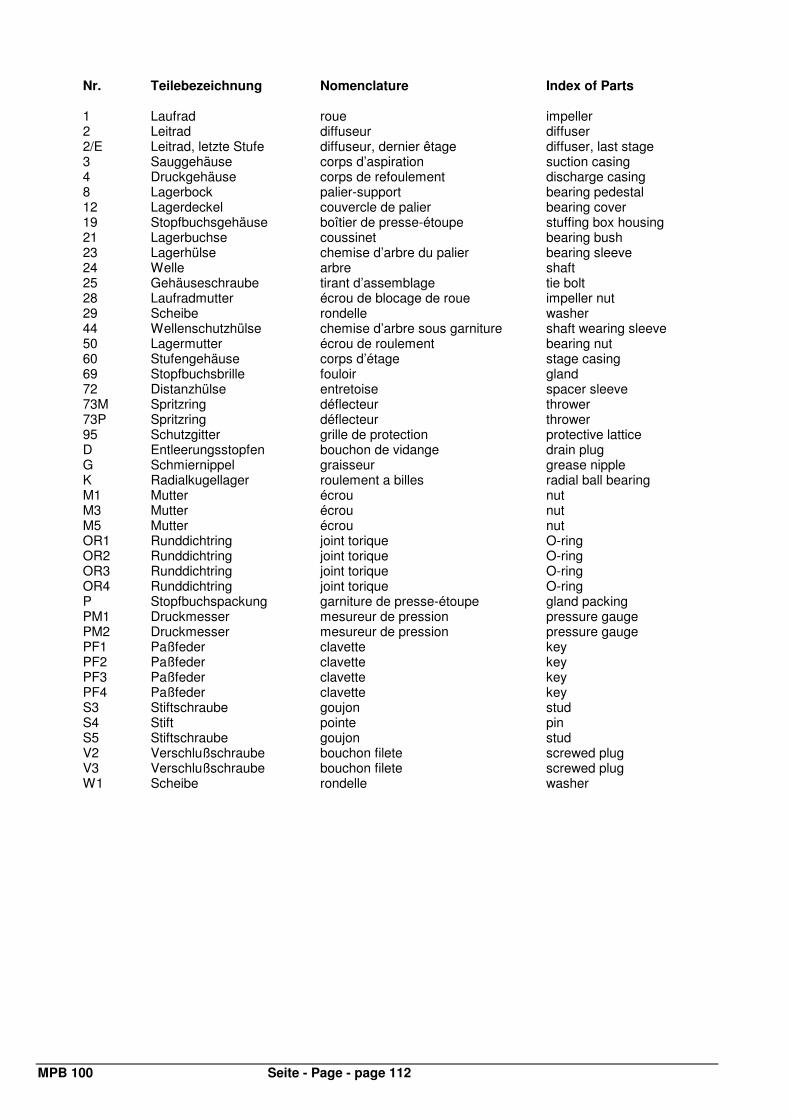
MPB 100 Seite - Page - page 112
Nr. Teilebezeichnung Nomenclature Index of Parts
1 Laufrad roue impeller 2 Leitrad diffuseur diffuser 2/E Leitrad, letzte Stufe diffuseur, dernier êtage diffuser, last stage 3 Sauggehäuse corps d’aspiration suction casing 4 Druckgehäuse corps de refoulement discharge casing 8 Lagerbock palier-support bearing pedestal 12 Lagerdeckel couvercle de palier bearing cover 19 Stopfbuchsgehäuse boîtier de presse-étoupe stuffing box housing 21 Lagerbuchse coussinet bearing bush 23 Lagerhülse chemise d’arbre du palier bearing sleeve 24 Welle arbre shaft 25 Gehäuseschraube tirant d’assemblage tie bolt 28 Laufradmutter écrou de blocage de roue impeller nut 29 Scheibe rondelle washer 44 Wellenschutzhülse chemise d’arbre sous garniture shaft wearing sleeve 50 Lagermutter écrou de roulement bearing nut 60 Stufengehäuse corps d’étage stage casing 69 Stopfbuchsbrille fouloir gland 72 Distanzhülse entretoise spacer sleeve 73M Spritzring déflecteur thrower 73P Spritzring déflecteur thrower 95 Schutzgitter grille de protection protective lattice D Entleerungsstopfen bouchon de vidange drain plug G Schmiernippel graisseur grease nipple K Radialkugellager roulement a billes radial ball bearing M1 Mutter écrou nut M3 Mutter écrou nut M5 Mutter écrou nut OR1 Runddichtring joint torique O-ring OR2 Runddichtring joint torique O-ring OR3 Runddichtring joint torique O-ring OR4 Runddichtring joint torique O-ring P Stopfbuchspackung garniture de presse-étoupe gland packing PM1 Druckmesser mesureur de pression pressure gauge PM2 Druckmesser mesureur de pression pressure gauge PF1 Paßfeder clavette key PF2 Paßfeder clavette key PF3 Paßfeder clavette key PF4 Paßfeder clavette key S3 Stiftschraube goujon stud S4 Stift pointe pin S5 Stiftschraube goujon stud V2 Verschlußschraube bouchon filete screwed plug V3 Verschlußschraube bouchon filete screwed plug W1 Scheibe rondelle washer
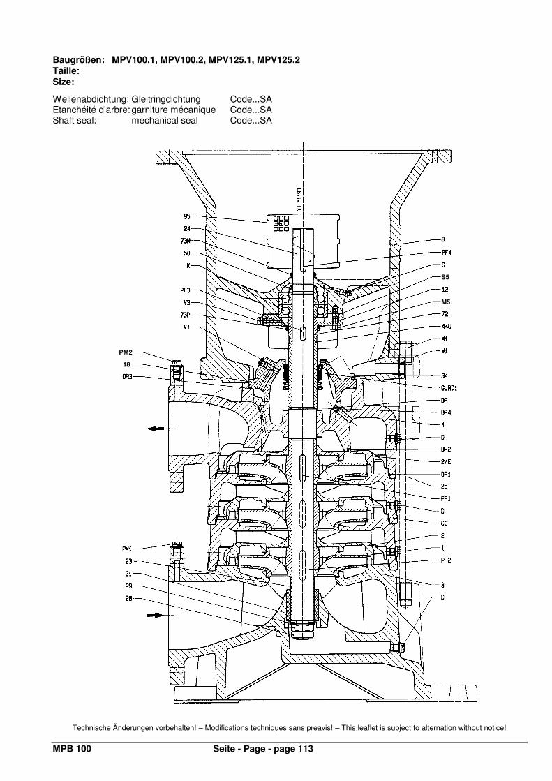
MPB 100 Seite - Page - page 113
Baugrößen: MPV100.1, MPV100.2, MPV125.1, MPV125.2 Taille: Size:
Wellenabdichtung: Gleitringdichtung Code...SA Etanchéité d’arbre: garniture mécanique Code...SA Shaft seal: mechanical seal Code...SA
Technische Änderungen vorbehalten! – Modifications techniques sans preavis! – This leaflet is subject to alternation without notice!
8
M5
PM2
S5
18
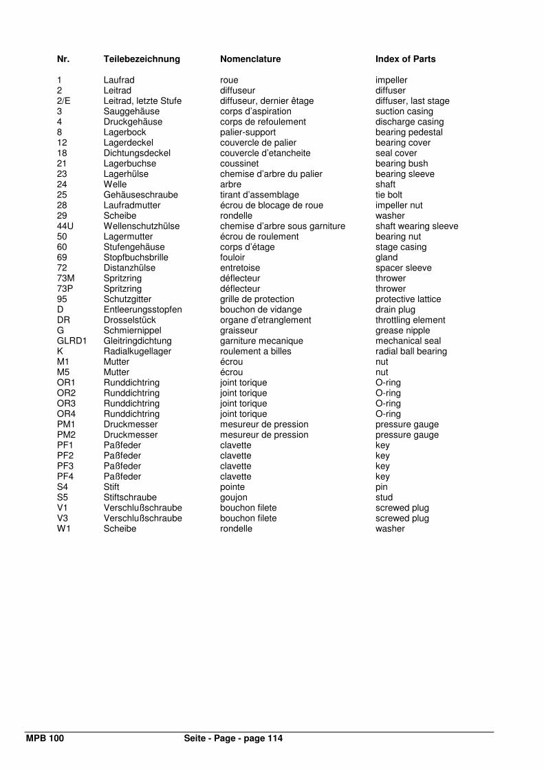
MPB 100 Seite - Page - page 114
Nr. Teilebezeichnung Nomenclature Index of Parts
1 Laufrad roue impeller 2 Leitrad diffuseur diffuser 2/E Leitrad, letzte Stufe diffuseur, dernier êtage diffuser, last stage 3 Sauggehäuse corps d’aspiration suction casing 4 Druckgehäuse corps de refoulement discharge casing 8 Lagerbock palier-support bearing pedestal 12 Lagerdeckel couvercle de palier bearing cover 18 Dichtungsdeckel couvercle d’etancheite seal cover 21 Lagerbuchse coussinet bearing bush 23 Lagerhülse chemise d’arbre du palier bearing sleeve 24 Welle arbre shaft 25 Gehäuseschraube tirant d’assemblage tie bolt 28 Laufradmutter écrou de blocage de roue impeller nut 29 Scheibe rondelle washer 44U Wellenschutzhülse chemise d’arbre sous garniture shaft wearing sleeve 50 Lagermutter écrou de roulement bearing nut 60 Stufengehäuse corps d’étage stage casing 69 Stopfbuchsbrille fouloir gland 72 Distanzhülse entretoise spacer sleeve 73M Spritzring déflecteur thrower 73P Spritzring déflecteur thrower 95 Schutzgitter grille de protection protective lattice D Entleerungsstopfen bouchon de vidange drain plug DR Drosselstück organe d’etranglement throttling element G Schmiernippel graisseur grease nipple GLRD1 Gleitringdichtung garniture mecanique mechanical seal K Radialkugellager roulement a billes radial ball bearing M1 Mutter écrou nut M5 Mutter écrou nut OR1 Runddichtring joint torique O-ring OR2 Runddichtring joint torique O-ring OR3 Runddichtring joint torique O-ring OR4 Runddichtring joint torique O-ring PM1 Druckmesser mesureur de pression pressure gauge PM2 Druckmesser mesureur de pression pressure gauge PF1 Paßfeder clavette key PF2 Paßfeder clavette key PF3 Paßfeder clavette key PF4 Paßfeder clavette key S4 Stift pointe pin S5 Stiftschraube goujon stud V1 Verschlußschraube bouchon filete screwed plug V3 Verschlußschraube bouchon filete screwed plug W1 Scheibe rondelle washer
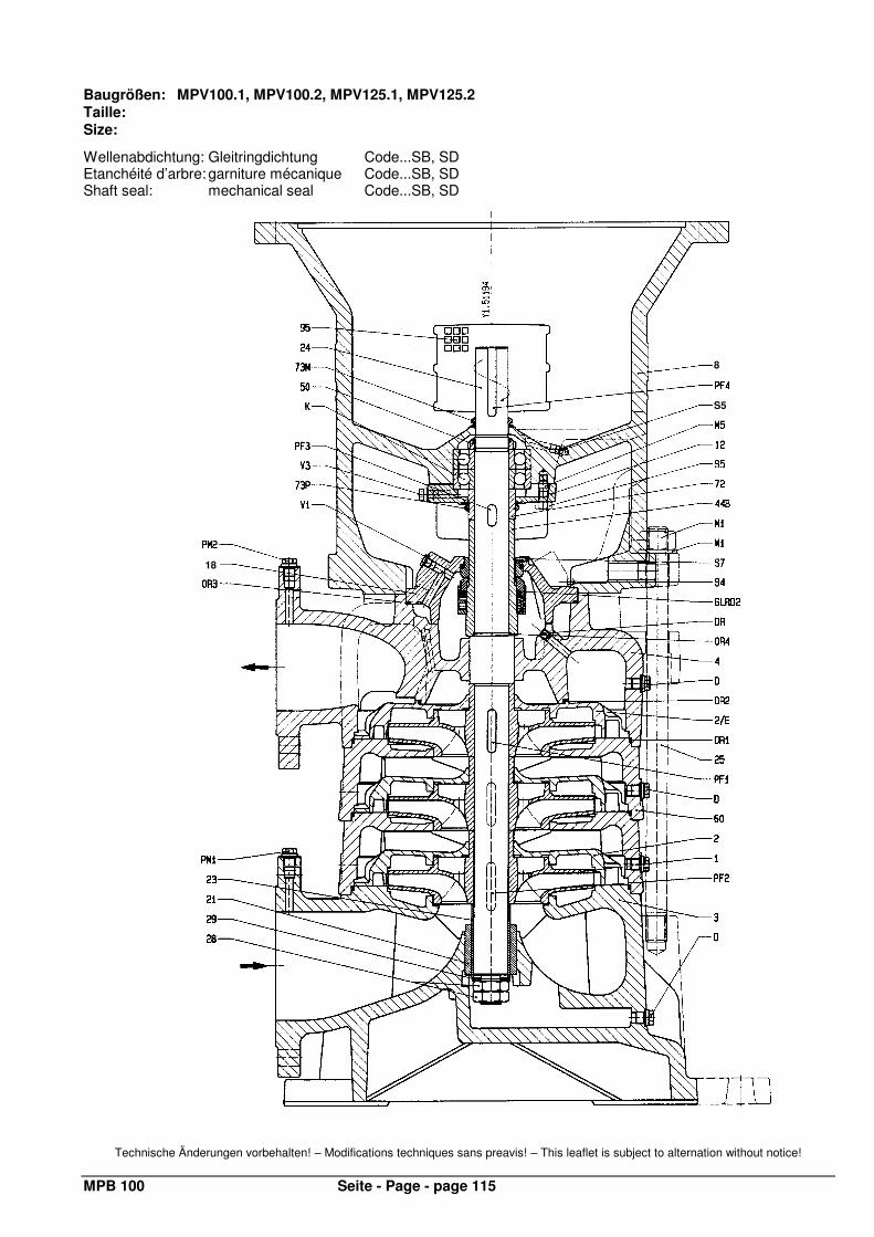
MPB 100 Seite - Page - page 115
Baugrößen: MPV100.1, MPV100.2, MPV125.1, MPV125.2 Taille: Size:
Wellenabdichtung: Gleitringdichtung Code...SB, SD Etanchéité d’arbre: garniture mécanique Code...SB, SD Shaft seal: mechanical seal Code...SB, SD
Technische Änderungen vorbehalten! – Modifications techniques sans preavis! – This leaflet is subject to alternation without notice!
18
8
S5
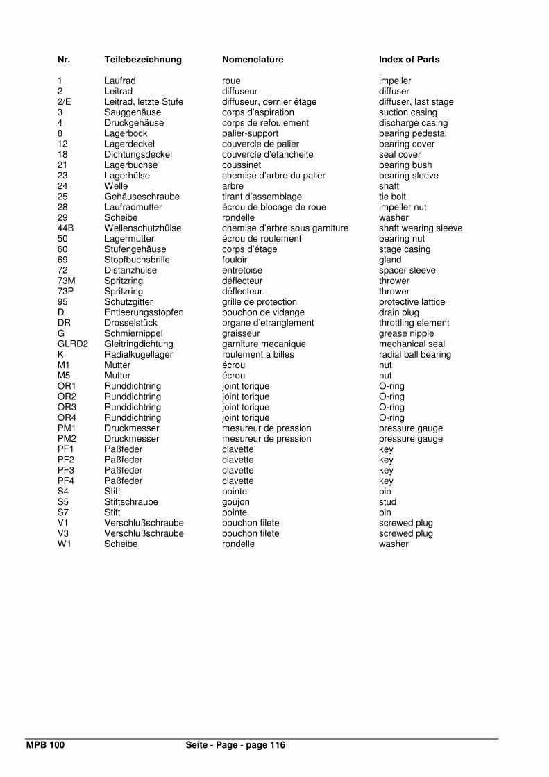
MPB 100 Seite - Page - page 116
Nr. Teilebezeichnung Nomenclature Index of Parts
1 Laufrad roue impeller 2 Leitrad diffuseur diffuser 2/E Leitrad, letzte Stufe diffuseur, dernier êtage diffuser, last stage 3 Sauggehäuse corps d’aspiration suction casing 4 Druckgehäuse corps de refoulement discharge casing 8 Lagerbock palier-support bearing pedestal 12 Lagerdeckel couvercle de palier bearing cover 18 Dichtungsdeckel couvercle d’etancheite seal cover 21 Lagerbuchse coussinet bearing bush 23 Lagerhülse chemise d’arbre du palier bearing sleeve 24 Welle arbre shaft 25 Gehäuseschraube tirant d’assemblage tie bolt 28 Laufradmutter écrou de blocage de roue impeller nut 29 Scheibe rondelle washer 44B Wellenschutzhülse chemise d’arbre sous garniture shaft wearing sleeve 50 Lagermutter écrou de roulement bearing nut 60 Stufengehäuse corps d’étage stage casing 69 Stopfbuchsbrille fouloir gland 72 Distanzhülse entretoise spacer sleeve 73M Spritzring déflecteur thrower 73P Spritzring déflecteur thrower 95 Schutzgitter grille de protection protective lattice D Entleerungsstopfen bouchon de vidange drain plug DR Drosselstück organe d’etranglement throttling element G Schmiernippel graisseur grease nipple GLRD2 Gleitringdichtung garniture mecanique mechanical seal K Radialkugellager roulement a billes radial ball bearing M1 Mutter écrou nut M5 Mutter écrou nut OR1 Runddichtring joint torique O-ring OR2 Runddichtring joint torique O-ring OR3 Runddichtring joint torique O-ring OR4 Runddichtring joint torique O-ring PM1 Druckmesser mesureur de pression pressure gauge PM2 Druckmesser mesureur de pression pressure gauge PF1 Paßfeder clavette key PF2 Paßfeder clavette key PF3 Paßfeder clavette key PF4 Paßfeder clavette key S4 Stift pointe pin S5 Stiftschraube goujon stud S7 Stift pointe pin V1 Verschlußschraube bouchon filete screwed plug V3 Verschlußschraube bouchon filete screwed plug W1 Scheibe rondelle washer
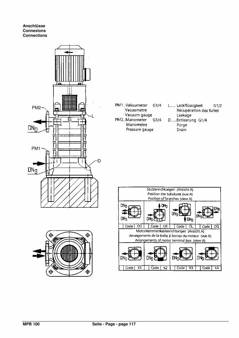
MPB 100 Seite - Page - page 117
Anschlüsse Connexions Connections
PM1
PM2
D
L

ITT Austria GmbH Ernst Vogel-Straße 2 A-2000 Stockerau Telefon: (+43) 2266/604 Telefax: (+43) 2266/65311 E-Mail: [email protected] Internet: www.ittaustria.com


![Servo-Getriebe - scope-online.de · Getriebetyp MPR MPG MPV SK SKH SKPR SKPG ML MH MKS MKSH Zeichen Einheit Getriebekennzahlen Übersetzungen i [-] 3 bis 100 3 bis 10 12 bis 100 3](https://img.pdfslide.org/doc/110x75/5e1e1fc2b2ea8d50fb7d88e5/servo-getriebe-scope-getriebetyp-mpr-mpg-mpv-sk-skh-skpr-skpg-ml-mh-mks-mksh.jpg)