Embed Size (px)
Citation preview
Adhesive Application Solutions | ISO 9001 certified
DYNAFLEX Hoses Technical Documentation, No. 30-07, Rev.8.16
ITW Dynatec
An Illinois Tool Works Company www.itwdynatec.com
ITW Dynatec Information about this manual
Page 2 Dynaflex Hose, Manual #30-07, Rev.8.16
Information about this manual
Read all instructions before operating this equipment! It is the customer’s responsibility to have all operators and service personnel read and understand this information. Contact your ITW Dynatec customer service representative for additional copies.
ITW Dynatec Service Parts and Technical Service:
AMERICAS
EUROPE, MIDDLE EAST & AFRICA
ASIA PACIFIC
ITW Dynatec 31 Volunteer Drive Hendersonville, TN 37075 USA Tel. +1.615.824.3634 [email protected] [email protected]
ITW Dynatec Industriestrasse 28 40822 Mettmann Germany Tel. +49.2104.915.0 [email protected] [email protected]
ITW Dynatec Unit2, B1 Building No.9 Weixin Road SIP, Suzhou, 215122 China Tel. +86.512.6289.0620 [email protected] [email protected]
ITW Dynatec Tsukimura Building 5th Floor 26-11, Nishikamata 7-chome Ota-ku, Tokyo 144-0051, Japan Tel. +81.3.5703.5501 [email protected] [email protected]
NOTICE: Please be sure to include the serial number of your application system each time you order replacement parts and/or supplies. This will enable us to send you the correct items that you need.
Index ITW Dynatec
Dynaflex Hose, Manual #30-07, Rev.8.16 Page 3
Index Information about this manual ................................................ 2
Index .......................................................................................... 3
Chapter 1 Safety Instructions ................................................. 5
General Considerations ............................................................................................................ 5 Safety Symbols in this Manual .................................................................................................. 5 Safe Installation and Operation ................................................................................................. 6 Explosion/ Fire Hazard .............................................................................................................. 6 Use of PUR (Polyurethane) Adhesives ..................................................................................... 6 Eye Protection & Protective Clothing ........................................................................................ 7 Electrical .................................................................................................................................... 7 Lockout/ Tagout ........................................................................................................................ 7 High Temperatures ................................................................................................................... 8 High Pressure ........................................................................................................................... 8 Servicing, maintenance ............................................................................................................. 8 Secure transport ........................................................................................................................ 9 Treatment for Burns from Hot Melt Adhesives .......................................................................... 9 Measures in case of fire .......................................................................................................... 10 Keep attention to environmental protection standards ........................................................... 10
Chapter 2 Description and Technical Specs ....................... 11
2.1 Applicable Safety Regulations ...................................................................... 11 Intended Use ........................................................................................................................... 11 Unintended Use, Examples..................................................................................................... 11 Residual Risks ........................................................................................................................ 11 Technical changes .................................................................................................................. 12 Using foreign components ...................................................................................................... 12 Setting-up operation ................................................................................................................ 12
2.2 Description Dynaflex Hoses .......................................................................... 13 Description .............................................................................................................................. 13 Specifications .......................................................................................................................... 14
2.3 Installation Instructions ................................................................................. 15 Typical Installation ................................................................................................................... 15 Hose Installation and Handling Guidelines ............................................................................. 17
2.4 To Disconnect Hose from ASU or Applicator ................................................ 18
Chapter 3 Troubleshooting ................................................... 19
Hose Troubleshooting Tip ....................................................................................................... 19 Troubleshooting Heaters and RTD Sensors in Dynaflex Hoses ............................................. 19 Circular plug ............................................................................................................................ 22 Resistance Table Temperature Sensor PT100 RTD IEC 751 / DIN EN 60751 ...................... 22 Rectangular plug ..................................................................................................................... 23 Resistance Table Temperature Sensor Ni120 RTD ............................................................... 23
Chapter 4 Available Options & Accessories ........................ 25
Typical Dynaflex DynaControl Hoses ..................................................................................... 25 Abrasion Resistant DynaControl Hoses, #6 (0.313” ID / DN8) ............................................... 28 Washdown DCL Hoses, #6 (0.313” ID / DN8) ........................................................................ 28 Challenger Hoses (0.313” ID / DN8), Sensor Ni 120 .............................................................. 29 Spray (Swirl) Air Regulator Kit ................................................................................................ 29

ITW Dynatec Index
Page 4 Dynaflex Hose, Manual #30-07, Rev.8.16
Hanger Strap Kit PN 113342................................................................................................... 30 Accessories ............................................................................................................................. 30
Chapter 5 Schematics ............................................................ 31
Pin Connectors for Dynaflex Hose .......................................................................................... 31 Schematics 101082-G: DynaControl Hoses ........................................................................... 32 Schematic 112633, Rev.A: DynaControl 2-Heater Hoses ...................................................... 33 Schematic 100951, Rev. B: Hose Nordson ............................................................................ 34
Chapter 1 Safety Instructions
ITW Dynatec
Dynaflex Hose, Manual #30-07, Rev.8.16 Page 5
Chapter 1 Safety Instructions
General Considerations
All operators and service personnel must read and understand this manual before operating or servicing equipment.
All maintenance and service on this equipment must be performed by trained technicians.
Read and adhere to the manual!
1. Read and follow these instructions. Failure to do this could result in severe personal injury or death.
2. Keep the binding rules for accident prevention valid for your country and the place of installation. Also keep the approved qualified technical rules for safety-conscious and professional work.
3. Additional safety instructions and/ or symbols are located throughout this manual.
They serve to warn maintenance personnel and operators about potentially hazardous situations.
4. Subject to technical modifications without notice!
5. To ensure proper operation of the equipment, use specified electrical supply sources.
6. Do not attempt to alter the design of the equipment unless written approval is received from ITW Dynatec.
7. Keep all manuals readily accessible at all times and refer to it often for the best performance from your equipment.
Safety Symbols in this Manual
1. WARNINGS and CAUTIONS are found throughout this manual. WARNINGS mean that failure to observe the specific instructions may cause injury to personnel.
2. CAUTIONS mean that failure to observe the specific instructions may damage the
equipment.
ITW Dynatec Chapter 1 Safety Instructions
Page 6 Dynaflex Hose, Manual #30-07, Rev.8.16
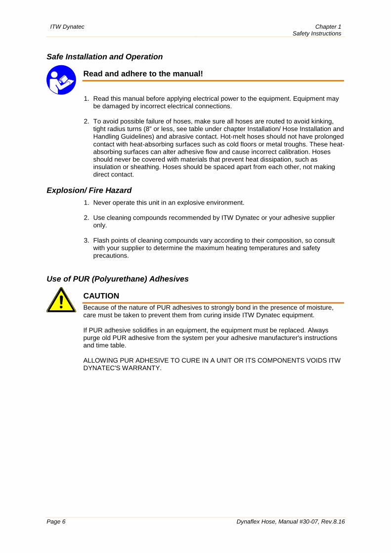
Safe Installation and Operation
Read and adhere to the manual!
1. Read this manual before applying electrical power to the equipment. Equipment may be damaged by incorrect electrical connections.
2. To avoid possible failure of hoses, make sure all hoses are routed to avoid kinking,
tight radius turns (8” or less, see table under chapter Installation/ Hose Installation and Handling Guidelines) and abrasive contact. Hot‐melt hoses should not have prolonged contact with heat‐absorbing surfaces such as cold floors or metal troughs. These heat‐absorbing surfaces can alter adhesive flow and cause incorrect calibration. Hoses should never be covered with materials that prevent heat dissipation, such as insulation or sheathing. Hoses should be spaced apart from each other, not making direct contact.
Explosion/ Fire Hazard
1. Never operate this unit in an explosive environment. 2. Use cleaning compounds recommended by ITW Dynatec or your adhesive supplier
only.
3. Flash points of cleaning compounds vary according to their composition, so consult with your supplier to determine the maximum heating temperatures and safety precautions.
Use of PUR (Polyurethane) Adhesives
CAUTION
Because of the nature of PUR adhesives to strongly bond in the presence of moisture, care must be taken to prevent them from curing inside ITW Dynatec equipment. If PUR adhesive solidifies in an equipment, the equipment must be replaced. Always purge old PUR adhesive from the system per your adhesive manufacturer's instructions and time table. ALLOWING PUR ADHESIVE TO CURE IN A UNIT OR ITS COMPONENTS VOIDS ITW DYNATEC'S WARRANTY.
Chapter 1 Safety Instructions
ITW Dynatec
Dynaflex Hose, Manual #30-07, Rev.8.16 Page 7
Eye Protection & Protective Clothing
WARNING EYE PROTECTION & PROTECTIVE CLOTHING REQUIRED 1. It is very important that you PROTECT YOUR EYES when working around
hot melt adhesive equipment! 2. Wear a face shield conforming to ANSI Z87.1 or safety glasses with side
shields which conform to ANSI Z87.1 or EN166.
3. Failure to wear a face shield or safety glasses could result in severe eye injury.
4. It is important to protect yourself from potential burns when working around hot melt
adhesive equipment.
5. Wear heat-resistant protective gloves and long‐sleeved, protective clothing to prevent burns that could result from contact with hot material or hot components.
6. Always wear steel‐reinforced safety shoes. Electrical
DANGER HIGH VOLTAGE 1. Dangerous voltages exist at several points in this equipment. To avoid personal injury,
do not touch exposed connections and components while input power is on. 2. A secure connection to a reliable earth ground is essential for safe operation. 3. An electrical disconnect switch with lockout capability must be provided in the line
ahead of the equipment. Wiring used to supply electrical power should be installed by a qualified electrician.
4. Notify the maintenance personnel immediately, if cables are damaged. Provide for
exchanging the defective components immediately. Lockout/ Tagout
Switch the unit voltage-free before working! Main switch OFF! 1. Follow OSHA 1910.147 (Lockout/ Tagout Regulation) for equipment's lockout
procedures and other important lockout/tagout guidelines. 2. Be familiar with all lockout sources on the equipment. 3. Even after the equipment has been locked out, there may be stored energy in the
application system, particularly in the capacitors within the panel box. To ensure that all stored energy is relieved, wait at least one minute after removing power before servicing electrical capacitors.
ITW Dynatec Chapter 1 Safety Instructions
Page 8 Dynaflex Hose, Manual #30-07, Rev.8.16
High Temperatures
WARNING HOT SURFACE
1. Severe burns can occur if unprotected skin comes in contact with molten adhesive or
hot application system parts. 2. Face shields (preferred) or safety glasses (for minimum protection), heat-resistant
protective gloves and long-sleeved clothing must be worn whenever working with or around adhesive application systems.
High Pressure
WARNING HIGH PRESSURE PRESENT
1. To prevent serious injury from molten adhesive under pressure when servicing the
equipment, disengage the pumps and relieve the adhesive system's hydraulic pressure (i.e. trigger the heads, hand‐held applicators, and/or other application devices into a waste container) before opening any hydraulic fittings or connections.
2. IMPORTANT NOTE: Even when a system's pressure gauge reads “0” psi, residual
pressure and trapped air can remain within it causing hot adhesive and pressure to escape without warning when a filter cap or a hose or hydraulic connection is loosened or removed. For this reason, always wear eye protection and protective clothing.
3. Either of the two High Pressure symbols shown may be used on ITW Dynatec
equipment. 4. Keep the given operating pressure. 5. Notify the maintenance personnel immediately, if hoses or components are damaged.
Provide for exchanging the defective components immediately. Servicing, maintenance
1. Only trained and qualified personnel are to operate and service this equipment. 2. Before any service work disconnect the external power supply and the pressure air
supply! 3. Any defects in the equipment that impact safe operation have to be repaired
immediately. 4. Check screws that have been loosened during the repair or maintenance, if they are
tight again. 5. Adhere to the current safety data sheet of the manufacturer when using hazardous
materials (cleaning agents, etc.)!
Chapter 1 Safety Instructions
ITW Dynatec
Dynaflex Hose, Manual #30-07, Rev.8.16 Page 9
Secure transport
1. Examine the equipment immediately after receipt, if it has been delivered in perfect condition.
2. Let damages in transit certify by the carrier and announce them immediately to the
ITW Dynatec. 3. The equipment has to cool down to room temperature before packaged and
transported. Treatment for Burns from Hot Melt Adhesives
Measures after being burned:
1. Burns caused by hot melt adhesive must be treated at a burn center. Provide the burn center's staff a copy of the adhesive's M.S.D.S. to expedite treatment.
2. Cool burnt parts immediately! 3. Do not remove adhesive forcibly from the skin! 4. Care should be used when working with hot melt adhesives in the molten state.
Because they rapidly solidify, they present a unique hazard. Even when first solidified, they are still hot and can cause severe burns.
5. When working near a hot melt application system, always wear safety shoes, heat-
resistant protective gloves, safety goggles and protective clothes that cover all vulnerable parts of the body.
6. Always have first-aid information and supplies available. 7. Call a physician and/or an emergency medical technician immediately. Let the burns
medicate by a medic immediately.
ITW Dynatec Chapter 1 Safety Instructions
Page 10 Dynaflex Hose, Manual #30-07, Rev.8.16
Measures in case of fire
1. Please heed that hot melt equipment may cause heavy burns. Risk of burns! 2. Work very carefully with molten hot melt. Keep in mind, that already jelled hot melt can
be very hot, too. 3. When working near a hot melt application system, always wear safety shoes, heat-
resistant protective gloves, safety goggles and protective clothes that cover all vulnerable parts of the body!
Measures in case of fire: Wear safety shoes, heat-resistant protective gloves, safety goggles and protective clothes that cover all vulnerable parts of the body. Firefighting - burning hot melt: Please keep attention to the safety data sheet given by the adhesive manufacturer.
EXTINGUISH FIRE Appropriate extinguishing agents: Foam extinguisher, Dry powder, Spray, Carbon dioxide (CO2), Dry sand. For safety reasons not appropriate extinguishing agents: None.
Firefighting - burning electrical equipment: Appropriate extinguishing agents: Carbon dioxide (CO2), Dry powder.
Keep attention to environmental protection standards
1. When working on or with the equipment, the legal obligations for waste avoidance and the duly recycling / disposals have to be fulfilled.
2. Keep attention, that during installations, repairs or maintenance matters hazardous to water, like adhesive / adhesive scrap, lubricating grease or oil, hydraulic oil, coolant and cleaner containing solvent not pollute the ground or get into the canalization!
3. These matters have to be caught, kept, transported and disposed in appropriate reservoirs!
4. Dispose these matters according to the international, national and regional
regulations.
Chapter 2 Description and Technical Specs
ITW Dynatec
Dynaflex Hose, Manual #30-07, Rev.8.16 Page 11
Chapter 2 Description and Technical Specs
2.1 Applicable Safety Regulations Intended Use
The Dynaflex hose may be used only to supply suitable materials, e.g. adhesives, from an Adhesive Supply Unit to an Applicator. When in doubt, seek permission from ITW Dynatec.
If the hose is not used in accordance with this regulation, a safe operation cannot be guaranteed. The operator - and not ITW Dynatec - is liable for all personal injury or property damages resulting from unintended use!
Intended use includes, that you • read this documentation, • heed all given warnings and safety instructions.
Any other use is considered to be unintended.
Unintended Use, Examples
The Dynaflex hose may not be used under the following conditions: • In defective condition. • In a potentially explosive atmosphere. • With unsuitable operating/processing materials. • When the values stated under Specifications are not complied with.
The Dynaflex hose may not be used to process the following materials: • Toxic, explosive and easily flammable materials. • Erosive and corrosive materials. • Food products.
Residual Risks
In the design of the Dynaflex hose, every measure was taken to protect personnel from potential danger. However, some residual risks cannot be avoided. Personnel should be aware of the following:
• Risk of burns from hot material and hose. • Risk of burns when attaching and removing heated hoses. • Material fumes can be hazardous. Avoid inhalation. If necessary, exhaust material
vapors and/or provide sufficient ventilation of the location of the system.
ITW Dynatec Chapter 2 Description and Technical Specs
Page 12 Dynaflex Hose, Manual #30-07, Rev.8.16
Technical changes
Any kind of technical changes having impact to the security or the operational liability of the system should only be done by written agreement of ITW Dynatec. Suchlike changes made without given a corresponding written agreement will lead to immediate exclusion of liability granted by ITW Dynatec for all direct and indirect subsequent damages.
Using foreign components
ITW Dynatec takes no responsibility for consequential damages caused by using foreign components or controllers that have not been provided or installed by ITW Dynatec. ITW Dynatec does not guarantee that foreign components or controllers used by the operating company are compatible to the ITW Dynatec-system.
Setting-up operation
We recommend asking for an ITW Dynatec-service technician for the setting-up operation, to ensure a functioning system. Let yourself and the people working with or working on the system be introduced to the system on this occasion. ITW Dynatec takes no responsibility for damages or faults caused by any untrained personal.
Chapter 2 Description and Technical Specs
ITW Dynatec
Dynaflex Hose, Manual #30-07, Rev.8.16 Page 13
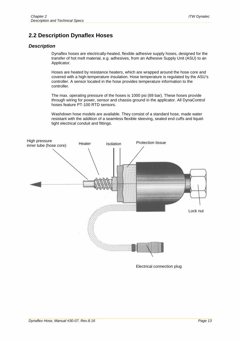
2.2 Description Dynaflex Hoses Description
Dynaflex hoses are electrically-heated, flexible adhesive supply hoses, designed for the transfer of hot melt material, e.g. adhesives, from an Adhesive Supply Unit (ASU) to an Applicator. Hoses are heated by resistance heaters, which are wrapped around the hose core and covered with a high-temperature insulation. Hose temperature is regulated by the ASU’s controller. A sensor located in the hose provides temperature information to the controller. The max. operating pressure of the hoses is 1000 psi (69 bar). These hoses provide through wiring for power, sensor and chassis ground in the applicator. All DynaControl hoses feature PT-100 RTD sensors. Washdown hose models are available. They consist of a standard hose, made water resistant with the addition of a seamless flexible sleeving, sealed end cuffs and liquid-tight electrical conduit and fittings.
High pressure inner tube (hose core)
Heater
Isolation
Protection tissue
Lock nut
Electrical connection plug
ITW Dynatec Chapter 2 Description and Technical Specs
Page 14 Dynaflex Hose, Manual #30-07, Rev.8.16
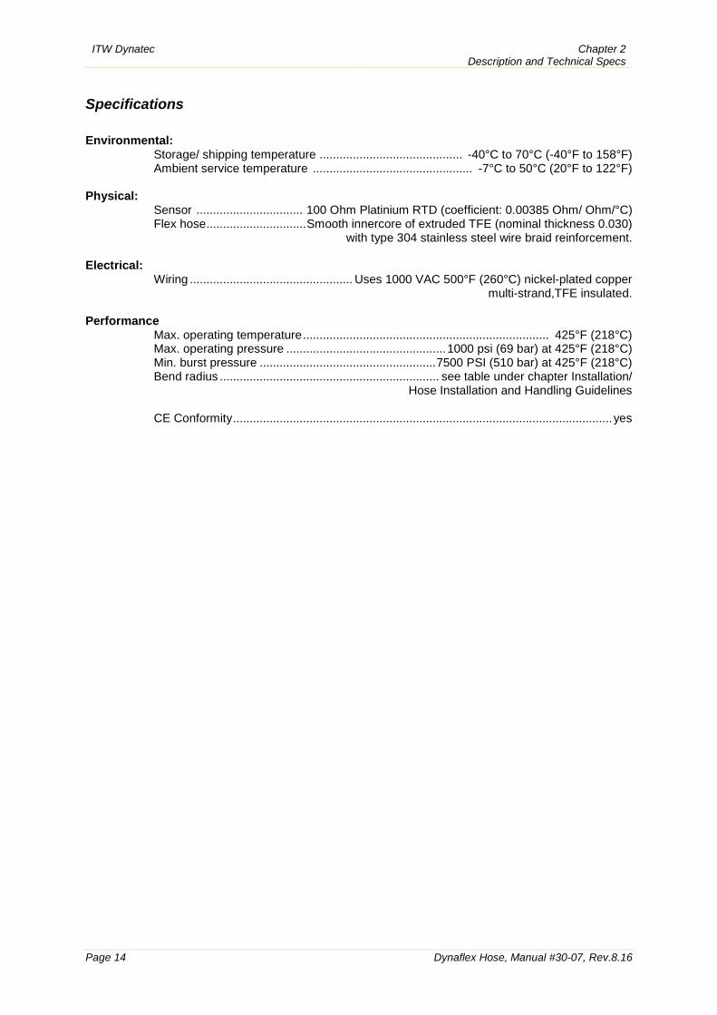
Specifications Environmental:
Storage/ shipping temperature ........................................... -40°C to 70°C (-40°F to 158°F) Ambient service temperature ................................................ -7°C to 50°C (20°F to 122°F)
Physical:
Sensor ................................ 100 Ohm Platinium RTD (coefficient: 0.00385 Ohm/ Ohm/°C) Flex hose .............................. Smooth innercore of extruded TFE (nominal thickness 0.030)
with type 304 stainless steel wire braid reinforcement. Electrical:
Wiring ................................................. Uses 1000 VAC 500°F (260°C) nickel-plated copper multi-strand,TFE insulated.
Performance
Max. operating temperature .......................................................................... 425°F (218°C) Max. operating pressure ................................................ 1000 psi (69 bar) at 425°F (218°C) Min. burst pressure ..................................................... 7500 PSI (510 bar) at 425°F (218°C) Bend radius .................................................................. see table under chapter Installation/
Hose Installation and Handling Guidelines CE Conformity .................................................................................................................. yes
Chapter 2 Description and Technical Specs
ITW Dynatec
Dynaflex Hose, Manual #30-07, Rev.8.16 Page 15
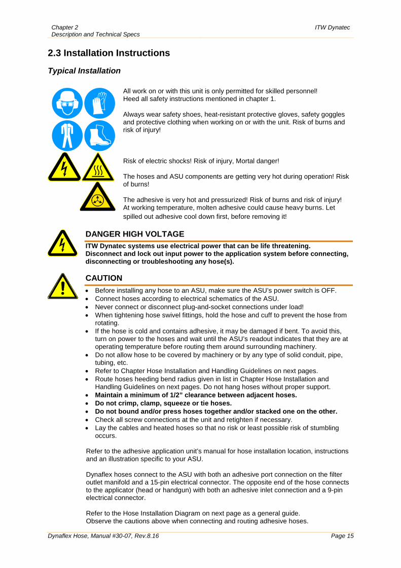
2.3 Installation Instructions Typical Installation
All work on or with this unit is only permitted for skilled personnel! Heed all safety instructions mentioned in chapter 1. Always wear safety shoes, heat-resistant protective gloves, safety goggles and protective clothing when working on or with the unit. Risk of burns and risk of injury! Risk of electric shocks! Risk of injury, Mortal danger! The hoses and ASU components are getting very hot during operation! Risk of burns! The adhesive is very hot and pressurized! Risk of burns and risk of injury! At working temperature, molten adhesive could cause heavy burns. Let spilled out adhesive cool down first, before removing it!
DANGER HIGH VOLTAGE
ITW Dynatec systems use electrical power that can be life threatening. Disconnect and lock out input power to the application system before connecting, disconnecting or troubleshooting any hose(s).
CAUTION
• Before installing any hose to an ASU, make sure the ASU’s power switch is OFF. • Connect hoses according to electrical schematics of the ASU. • Never connect or disconnect plug-and-socket connections under load! • When tightening hose swivel fittings, hold the hose and cuff to prevent the hose from
rotating. • If the hose is cold and contains adhesive, it may be damaged if bent. To avoid this,
turn on power to the hoses and wait until the ASU’s readout indicates that they are at operating temperature before routing them around surrounding machinery.
• Do not allow hose to be covered by machinery or by any type of solid conduit, pipe, tubing, etc.
• Refer to Chapter Hose Installation and Handling Guidelines on next pages. • Route hoses heeding bend radius given in list in Chapter Hose Installation and
Handling Guidelines on next pages. Do not hang hoses without proper support. • Maintain a minimum of 1/2” clearance between adjacent hoses. • Do not crimp, clamp, squeeze or tie hoses. • Do not bound and/or press hoses together and/or stacked one on the other. • Check all screw connections at the unit and retighten if necessary. • Lay the cables and heated hoses so that no risk or least possible risk of stumbling
occurs.
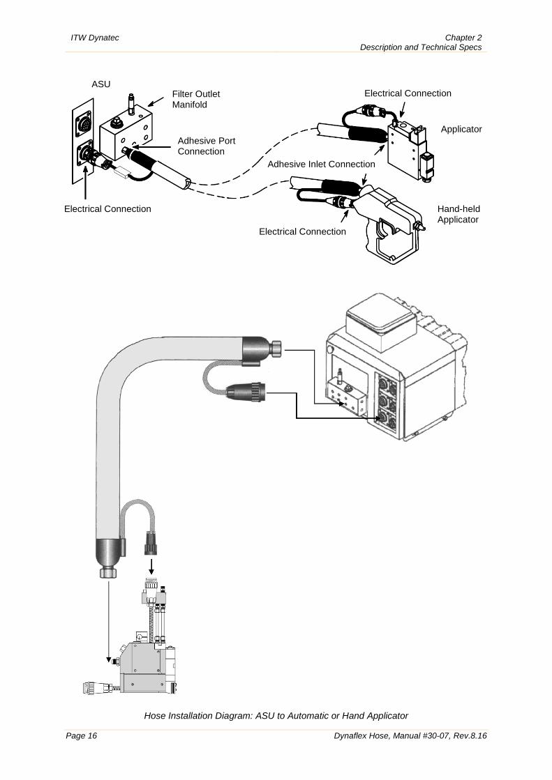
Refer to the adhesive application unit’s manual for hose installation location, instructions and an illustration specific to your ASU. Dynaflex hoses connect to the ASU with both an adhesive port connection on the filter outlet manifold and a 15-pin electrical connector. The opposite end of the hose connects to the applicator (head or handgun) with both an adhesive inlet connection and a 9-pin electrical connector. Refer to the Hose Installation Diagram on next page as a general guide. Observe the cautions above when connecting and routing adhesive hoses.
ITW Dynatec Chapter 2 Description and Technical Specs
Page 16 Dynaflex Hose, Manual #30-07, Rev.8.16
Hose Installation Diagram: ASU to Automatic or Hand Applicator
Electrical Connection
Electrical Connection
Electrical Connection ASU
Filter Outlet Manifold
Adhesive Port Connection
Adhesive Inlet Connection
Applicator
Hand-held Applicator
Chapter 2 Description and Technical Specs
ITW Dynatec
Dynaflex Hose, Manual #30-07, Rev.8.16 Page 17
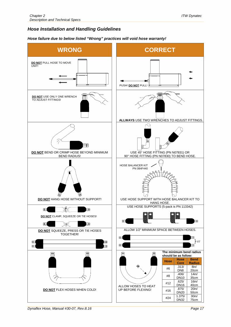
Hose Installation and Handling Guidelines
Hose failure due to below listed “Wrong” practices will void hose warranty!
WRONG CORRECT
ALLWAYS USE TWO WRENCHES TO ADJUST FITTINGS.
DO NOT BEND OR CRIMP HOSE BEYOND MINIMUM
BEND RADIUS!
USE 45° HOSE FITTING (PN N07831) OR
90° HOSE FITTING (PN N07830) TO BEND HOSE.
DO NOT HANG HOSE WITHOUT SUPPORT!
USE HOSE SUPPORT WITH HOSE BALANCER KIT TO
HANG HOSE.
USE HOSE SUPPORTS (5-pack is PN 113342)
DO NOT SQUEEZE, PRESS OR TIE HOSES TOGETHER!
ALLOW 1/2” MINIMUM SPACE BETWEEN HOSES.
DO NOT FLEX HOSES WHEN COLD!
ALLOW HOSES TO HEAT UP BEFORE FLEXING!
The minimum bend radius should be as follow:
Hose Hose Core
Bend Radius
#6 .313/ DN8
8in/ 20cm
#8 .406/ DN10
14in/ 35cm
#12 .625/ DN16
16in/ 40cm
#16 .875/ DN20
20in/ 50cm
#24 1.375/ DN32
30in/ 75cm
DO NOT PULL HOSE TO MOVE UNIT!
PUSH! DO NOT PULL!
HOSE BALANCER KIT PN 084F440
DO NOT CLAMP, SQUEEZE OR TIE HOSES!
DO NOT USE ONLY ONE WRENCH TO ADJUST FITTINGS!
1/2‘
ITW Dynatec Chapter 2 Description and Technical Specs
Page 18 Dynaflex Hose, Manual #30-07, Rev.8.16
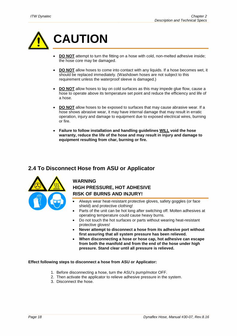
CAUTION • DO NOT attempt to turn the fitting on a hose with cold, non-melted adhesive inside;
the hose core may be damaged.
• DO NOT allow hoses to come into contact with any liquids. If a hose becomes wet, it should be replaced immediately. (Washdown hoses are not subject to this requirement unless the waterproof sleeve is damaged.)
• DO NOT allow hoses to lay on cold surfaces as this may impede glue flow, cause a hose to operate above its temperature set point and reduce the efficiency and life of a hose.
• DO NOT allow hoses to be exposed to surfaces that may cause abrasive wear. If a hose shows abrasive wear, it may have internal damage that may result in erratic operation, injury and damage to equipment due to exposed electrical wires, burning or fire.
• Failure to follow installation and handling guidelines WILL void the hose warranty, reduce the life of the hose and may result in injury and damage to equipment resulting from char, burning or fire.
2.4 To Disconnect Hose from ASU or Applicator
WARNING HIGH PRESSURE, HOT ADHESIVE RISK OF BURNS AND INJURY! • Always wear heat-resistant protective gloves, safety goggles (or face
shield) and protective clothing! • Parts of the unit can be hot long after switching off. Molten adhesives at
operating temperature could cause heavy burns. • Do not touch the hot surfaces or parts without wearing heat-resistant
protective gloves! • Never attempt to disconnect a hose from its adhesive port without
first assuring that all system pressure has been relieved. • When disconnecting a hose or hose cap, hot adhesive can escape
from both the manifold and from the end of the hose under high pressure. Stand clear until all pressure is relieved.
Effect following steps to disconnect a hose from ASU or Applicator:
1. Before disconnecting a hose, turn the ASU’s pump/motor OFF. 2. Then activate the applicator to relieve adhesive pressure in the system. 3. Disconnect the hose.
Chapter 3 Troubleshooting
ITW Dynatec
Dynaflex Hose, Manual #30-07, Rev.8.16 Page 19
Chapter 3 Troubleshooting
Hose Troubleshooting Tip
Hose problems can be isolated by electrically connecting the hose to an alternate socket on the ASU. If the malfunction goes with the hose, the problem will usually be in the hose that was moved. If the malfunction does not move with the hose, the problem is probably in the ASU.
Troubleshooting Heaters and RTD Sensors in Dynaflex Hoses
DANGER HIGH VOLTAGE Disconnect and lock out input power to the application system before proceeding with these instructions. The Hoses and Adhesive Supply Unit use electrical power that can be life threatening and hot‐melt adhesives that can cause serious burns. All troubleshooting procedures must be performed by qualified, trained technicians. Please re-read all security advices given in Chapter 1 before performing any troubleshooting procedures.
WARNING! HIGH PRESSURE, HOT ADHESIVE! Some of the procedures in the following Troubleshooting Guide require working near hot adhesive. Severe burns can occur if unprotected skin comes in contact with molten adhesive or hot application system parts. When disconnecting a hose or hose cap, hot adhesive can escape from both the manifold and from the end of the hose under high pressure. Stand clear until all pressure is relieved. Face shields (preferred) or safety glasses (for minimum protection), heat-resistant protective gloves and long-sleeved clothing must be worn whenever working with or around adhesive application systems.
ITW Dynatec Chapter 3 Troubleshooting
Page 20 Dynaflex Hose, Manual #30-07, Rev.8.16
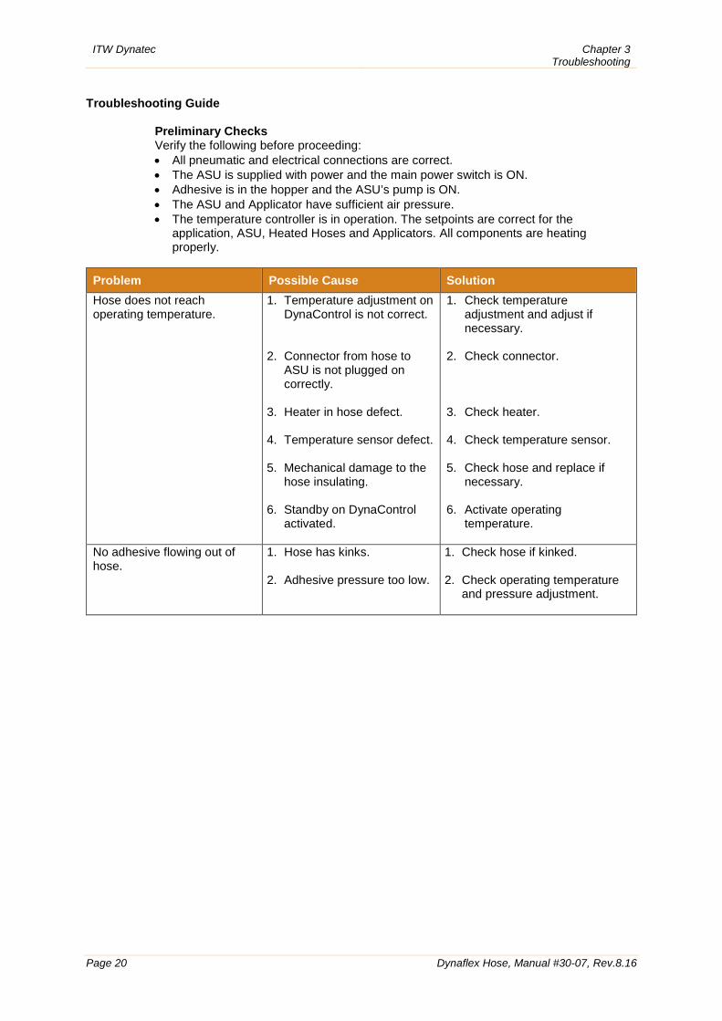
Troubleshooting Guide
Preliminary Checks Verify the following before proceeding: • All pneumatic and electrical connections are correct. • The ASU is supplied with power and the main power switch is ON. • Adhesive is in the hopper and the ASU’s pump is ON. • The ASU and Applicator have sufficient air pressure. • The temperature controller is in operation. The setpoints are correct for the
application, ASU, Heated Hoses and Applicators. All components are heating properly.
Problem Possible Cause Solution Hose does not reach operating temperature.
1. Temperature adjustment on DynaControl is not correct.
2. Connector from hose to ASU is not plugged on correctly.
3. Heater in hose defect.
4. Temperature sensor defect.
5. Mechanical damage to the hose insulating.
6. Standby on DynaControl activated.
1. Check temperature adjustment and adjust if necessary.
2. Check connector.
3. Check heater.
4. Check temperature sensor.
5. Check hose and replace if
necessary.
6. Activate operating temperature.
No adhesive flowing out of hose.
1. Hose has kinks.
2. Adhesive pressure too low.
1. Check hose if kinked.
2. Check operating temperature and pressure adjustment.
Chapter 3 Troubleshooting
ITW Dynatec
Dynaflex Hose, Manual #30-07, Rev.8.16 Page 21
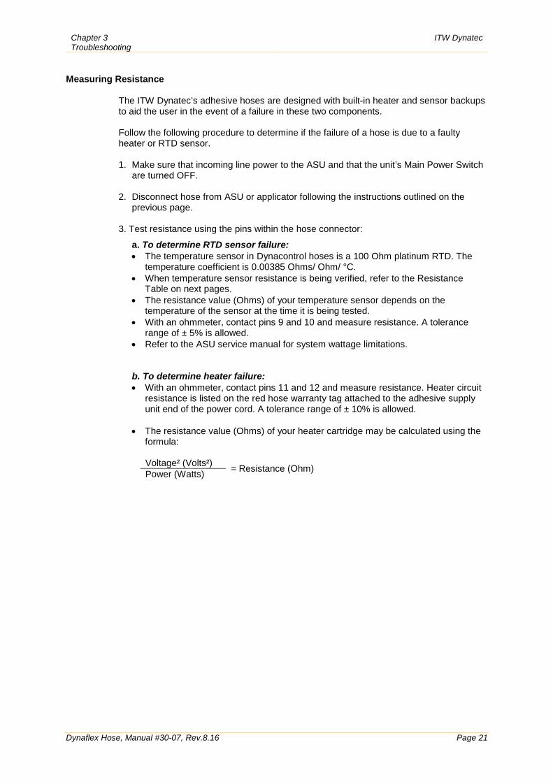
Measuring Resistance
The ITW Dynatec’s adhesive hoses are designed with built-in heater and sensor backups to aid the user in the event of a failure in these two components. Follow the following procedure to determine if the failure of a hose is due to a faulty heater or RTD sensor. 1. Make sure that incoming line power to the ASU and that the unit’s Main Power Switch
are turned OFF.
2. Disconnect hose from ASU or applicator following the instructions outlined on the previous page.
3. Test resistance using the pins within the hose connector:
a. To determine RTD sensor failure: • The temperature sensor in Dynacontrol hoses is a 100 Ohm platinum RTD. The
temperature coefficient is 0.00385 Ohms/ Ohm/ °C. • When temperature sensor resistance is being verified, refer to the Resistance
Table on next pages. • The resistance value (Ohms) of your temperature sensor depends on the
temperature of the sensor at the time it is being tested. • With an ohmmeter, contact pins 9 and 10 and measure resistance. A tolerance
range of ± 5% is allowed. • Refer to the ASU service manual for system wattage limitations. b. To determine heater failure: • With an ohmmeter, contact pins 11 and 12 and measure resistance. Heater circuit
resistance is listed on the red hose warranty tag attached to the adhesive supply unit end of the power cord. A tolerance range of ± 10% is allowed.
• The resistance value (Ohms) of your heater cartridge may be calculated using the
formula:
Voltage² (Volts²) = Resistance (Ohm) Power (Watts)
ITW Dynatec Chapter 3 Troubleshooting
Page 22 Dynaflex Hose, Manual #30-07, Rev.8.16
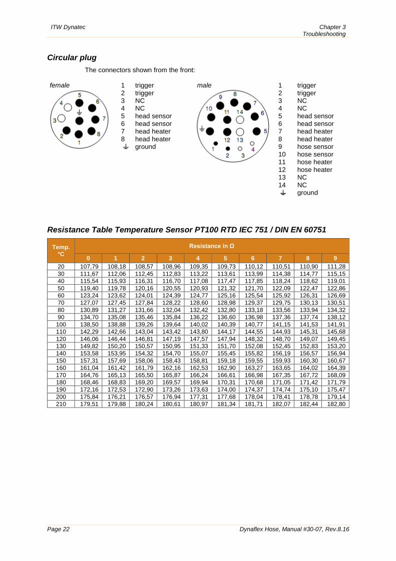
Circular plug
The connectors shown from the front: female
1 trigger 2 trigger 3 NC 4 NC 5 head sensor 6 head sensor 7 head heater 8 head heater
ground
male
1 trigger 2 trigger 3 NC 4 NC 5 head sensor 6 head sensor 7 head heater 8 head heater 9 hose sensor 10 hose sensor 11 hose heater 12 hose heater 13 NC 14 NC
ground
Resistance Table Temperature Sensor PT100 RTD IEC 751 / DIN EN 60751
Temp. °C
Resistance in Ω
0 1 2 3 4 5 6 7 8 9 20 107,79 108,18 108,57 108,96 109,35 109,73 110,12 110,51 110,90 111,28 30 111,67 112,06 112,45 112,83 113,22 113,61 113,99 114,38 114,77 115,15 40 115,54 115,93 116,31 116,70 117,08 117,47 117,85 118,24 118,62 119,01 50 119,40 119,78 120,16 120,55 120,93 121,32 121,70 122,09 122,47 122,86 60 123,24 123,62 124,01 124,39 124,77 125,16 125,54 125,92 126,31 126,69 70 127,07 127,45 127,84 128,22 128,60 128,98 129,37 129,75 130,13 130,51 80 130,89 131,27 131,66 132,04 132,42 132,80 133,18 133,56 133,94 134,32 90 134,70 135,08 135,46 135,84 136,22 136,60 136,98 137,36 137,74 138,12
100 138,50 138,88 139,26 139,64 140,02 140,39 140,77 141,15 141,53 141,91 110 142,29 142,66 143,04 143,42 143,80 144,17 144,55 144,93 145,31 145,68 120 146,06 146,44 146,81 147,19 147,57 147,94 148,32 148,70 149,07 149,45 130 149,82 150,20 150,57 150,95 151,33 151,70 152,08 152,45 152,83 153,20 140 153,58 153,95 154,32 154,70 155,07 155,45 155,82 156,19 156,57 156,94 150 157,31 157,69 158,06 158,43 158,81 159,18 159,55 159,93 160,30 160,67 160 161,04 161,42 161,79 162,16 162,53 162,90 163,27 163,65 164,02 164,39 170 164,76 165,13 165,50 165,87 166,24 166,61 166,98 167,35 167,72 168,09 180 168,46 168,83 169,20 169,57 169,94 170,31 170,68 171,05 171,42 171,79 190 172,16 172,53 172,90 173,26 173,63 174,00 174,37 174,74 175,10 175,47 200 175,84 176,21 176,57 176,94 177,31 177,68 178,04 178,41 178,78 179,14 210 179,51 179,88 180,24 180,61 180,97 181,34 181,71 182,07 182,44 182,80
Chapter 3 Troubleshooting
ITW Dynatec
Dynaflex Hose, Manual #30-07, Rev.8.16 Page 23
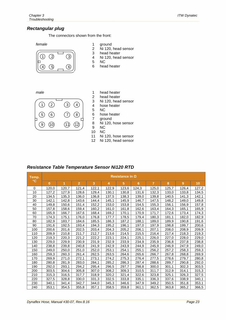
Rectangular plug The connectors shown from the front:
female
male
1 ground 2 Ni 120, head sensor 3 head heater 4 Ni 120, head sensor 5 NC 6 head heater
1 head heater 2 head heater 3 Ni 120, head sensor 4 hose heater 5 NC 6 hose heater 7 ground 8 Ni 120, hose sensor 9 NC 10 NC 11 Ni 120, hose sensor 12 Ni 120, head sensor
Resistance Table Temperature Sensor Ni120 RTD
Temp. °C
Resistance in Ω
0 1 2 3 4 5 6 7 8 9 10 0 120,0 120,7 121,4 122,1 122,9 123,6 124,3 125,0 125,7 126,4 127,2
10 127,2 127,9 128,6 129,4 130,1 130,8 131,6 132,3 133,0 133,8 134,5 20 134,5 135,3 136,0 136,8 137,5 138,3 139,0 139,8 140,5 141,3 142,1 30 142,1 142,8 143,6 144,4 145,1 145,9 146,7 147,5 148,2 149,0 149,8 40 149,8 150,6 151,4 152,2 153,0 153,8 154,5 155,3 156,1 156,9 157,8 50 157,8 158,6 159,4 160,2 161,0 161,8 162,6 163,4 164,3 165,1 165,9 60 165,9 166,7 167,6 168,4 169,2 170,1 170,9 171,7 172,6 173,4 174,3 70 174,3 175,1 176,0 176,8 177,7 178,5 179,4 180,3 181,1 182,0 182,9 80 182,9 183,7 184,6 185,5 186,3 187,2 188,1 189,0 189,9 190,8 191,6 90 191,6 192,5 193,4 194,3 195,2 196,1 197,0 197,9 198,8 199,7 200,6
100 200,6 201,6 202,5 203,4 204,3 205,2 206,1 207,1 208,0 208,9 209,9 110 209,9 210,8 211,7 212,7 213,6 214,5 215,5 216,4 217,4 218,3 219,3 120 219,3 220,3 221,2 222,2 223,1 224,1 225,1 226,0 227,0 228,0 229,0 130 229,0 229,9 230,9 231,9 232,9 233,9 234,9 235,9 236,8 237,8 238,8 140 238,8 239,8 240,8 241,9 242,9 243,9 244,9 245,9 246,9 247,9 249,0 150 249,0 250,0 251,0 252,0 253,1 254,1 255,1 256,2 257,2 258,3 259,3 160 259,3 260,3 261,4 262,5 263,5 264,6 265,6 266,7 267,8 268,8 269,9 170 269,9 271,0 272,1 273,1 274,2 275,3 276,4 277,5 278,6 279,7 280,8 180 280,8 281,9 283,0 284,1 285,2 286,3 287,4 288,6 289,7 290,8 292,0 190 292,0 293,1 294,2 295,4 296,5 297,7 298,8 300,0 301,1 302,3 303,5 200 303,5 304,6 305,8 307,0 308,2 309,3 310,5 311,7 312,9 314,1 315,3 210 315,3 316,5 317,7 318,9 320,2 321,4 322,6 323,8 325,1 326,3 327,5 220 327,5 328,8 330,0 331,3 332,5 333,8 335,1 336,3 337,6 338,9 340,1 230 340,1 341,4 342,7 344,0 345,3 346,6 347,9 349,2 350,5 351,8 353,1 240 353,1 354,5 355,8 357,1 358,5 359,8 361,1 362,5 363,8 365,2 366,5
1 2 3 4
5 6 7 8
9 10 11 12
1 2 3
4 5 6

ITW Dynatec Chapter 3 Troubleshooting
Page 24 Dynaflex Hose, Manual #30-07, Rev.8.16
This page intentionally left blank.
Chapter 4 Available Options & Accessories
ITW Dynatec
Dynaflex Hose, Manual #30-07, Rev.8.16 Page 25
Chapter 4 Available Options & Accessories
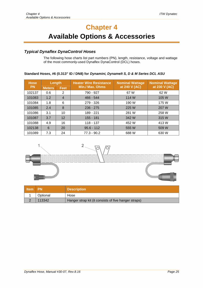
Typical Dynaflex DynaControl Hoses
The following hose charts list part numbers (PN), length, resistance, voltage and wattage of the most commonly-used Dynaflex DynaControl (DCL) hoses.
Standard Hoses, #6 (0.313” ID / DN8) for Dynamini, Dynamelt S, D & M Series DCL ASU
Hose PN
Length Heater Wire Resistance Min./ Max. Ohms
Nominal Wattage at 240 V (AC)
Nominal Wattage at 230 V (AC) Meters Feet
102137 0.6 2 790 - 927 67 W 62 W 101083 1.2 4 466 - 544 114 W 105 W 101084 1.8 6 279 - 326 190 W 175 W 101085 2.4 8 236 - 275 225 W 207 W 101086 3.1 10 189 - 221 281 W 258 W 101087 3.7 12 155 - 181 342 W 315 W 101088 4.9 16 118 - 137 452 W 413 W 102138 6 20 95.6 - 112 555 W 509 W 101089 7.3 24 77.3 - 90.2 688 W 630 W
Item PN Description
1 Optional Hose 2 113342 Hanger strap kit (it consists of five hanger straps)
ITW Dynatec Chapter 4 Available Options & Accessories
Page 26 Dynaflex Hose, Manual #30-07, Rev.8.16
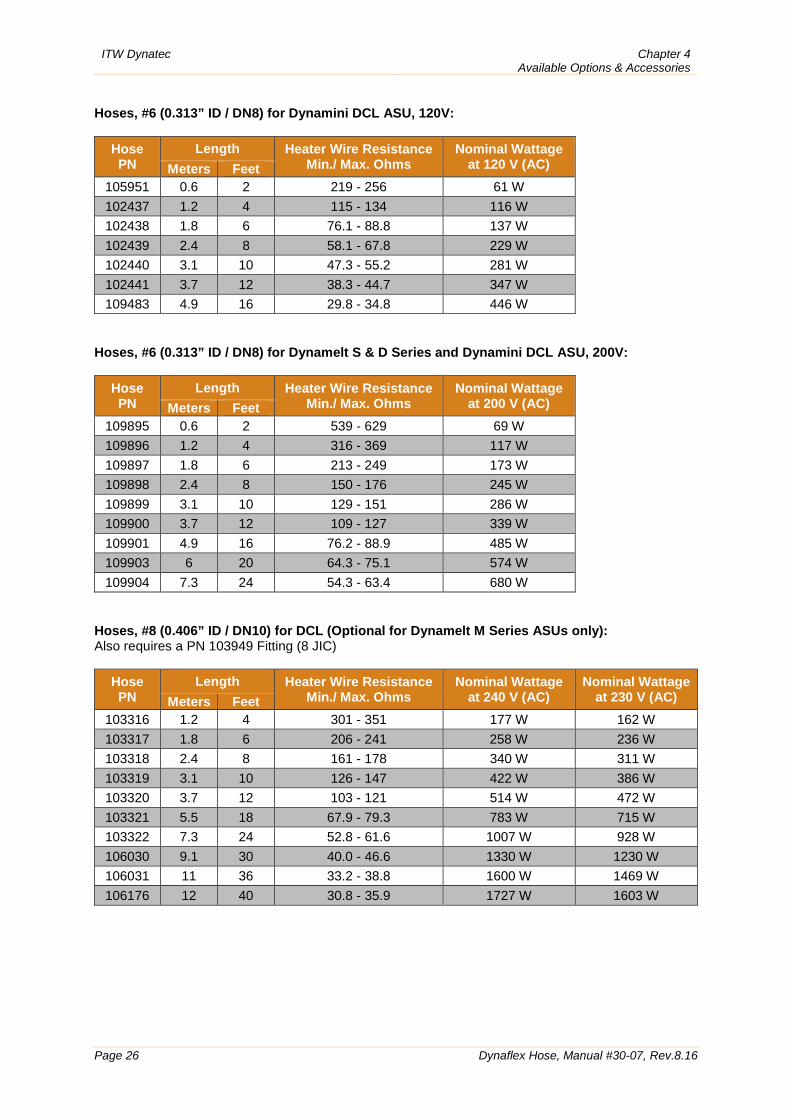
Hoses, #6 (0.313” ID / DN8) for Dynamini DCL ASU, 120V:
Hose PN
Length Heater Wire Resistance Min./ Max. Ohms
Nominal Wattage at 120 V (AC) Meters Feet
105951 0.6 2 219 - 256 61 W 102437 1.2 4 115 - 134 116 W 102438 1.8 6 76.1 - 88.8 137 W 102439 2.4 8 58.1 - 67.8 229 W 102440 3.1 10 47.3 - 55.2 281 W 102441 3.7 12 38.3 - 44.7 347 W 109483 4.9 16 29.8 - 34.8 446 W
Hoses, #6 (0.313” ID / DN8) for Dynamelt S & D Series and Dynamini DCL ASU, 200V:
Hose PN
Length Heater Wire Resistance Min./ Max. Ohms
Nominal Wattage at 200 V (AC) Meters Feet
109895 0.6 2 539 - 629 69 W 109896 1.2 4 316 - 369 117 W 109897 1.8 6 213 - 249 173 W 109898 2.4 8 150 - 176 245 W 109899 3.1 10 129 - 151 286 W 109900 3.7 12 109 - 127 339 W 109901 4.9 16 76.2 - 88.9 485 W 109903 6 20 64.3 - 75.1 574 W 109904 7.3 24 54.3 - 63.4 680 W
Hoses, #8 (0.406” ID / DN10) for DCL (Optional for Dynamelt M Series ASUs only): Also requires a PN 103949 Fitting (8 JIC)
Hose PN
Length Heater Wire Resistance Min./ Max. Ohms
Nominal Wattage at 240 V (AC)
Nominal Wattage at 230 V (AC) Meters Feet
103316 1.2 4 301 - 351 177 W 162 W 103317 1.8 6 206 - 241 258 W 236 W 103318 2.4 8 161 - 178 340 W 311 W 103319 3.1 10 126 - 147 422 W 386 W 103320 3.7 12 103 - 121 514 W 472 W 103321 5.5 18 67.9 - 79.3 783 W 715 W 103322 7.3 24 52.8 - 61.6 1007 W 928 W 106030 9.1 30 40.0 - 46.6 1330 W 1230 W 106031 11 36 33.2 - 38.8 1600 W 1469 W 106176 12 40 30.8 - 35.9 1727 W 1603 W
Chapter 4 Available Options & Accessories
ITW Dynatec
Dynaflex Hose, Manual #30-07, Rev.8.16 Page 27
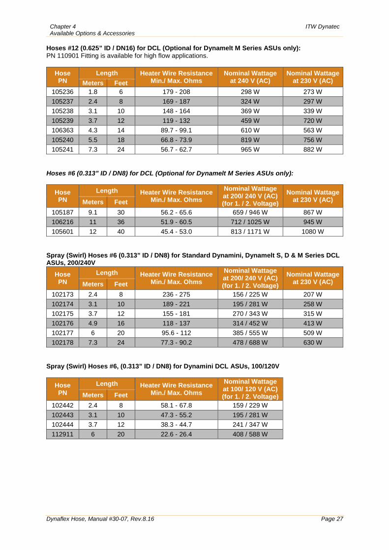
Hoses #12 (0.625” ID / DN16) for DCL (Optional for Dynamelt M Series ASUs only): PN 110901 Fitting is available for high flow applications.
Hose PN
Length Heater Wire Resistance Min./ Max. Ohms
Nominal Wattage at 240 V (AC)
Nominal Wattage at 230 V (AC) Meters Feet
105236 1.8 6 179 - 208 298 W 273 W 105237 2.4 8 169 - 187 324 W 297 W 105238 3.1 10 148 - 164 369 W 339 W 105239 3.7 12 119 - 132 459 W 720 W 106363 4.3 14 89.7 - 99.1 610 W 563 W 105240 5.5 18 66.8 - 73.9 819 W 756 W 105241 7.3 24 56.7 - 62.7 965 W 882 W
Hoses #6 (0.313” ID / DN8) for DCL (Optional for Dynamelt M Series ASUs only):
Hose PN
Length Heater Wire Resistance Min./ Max. Ohms
Nominal Wattage at 200/ 240 V (AC) (for 1. / 2. Voltage)
Nominal Wattage at 230 V (AC) Meters Feet
105187 9.1 30 56.2 - 65.6 659 / 946 W 867 W 106216 11 36 51.9 - 60.5 712 / 1025 W 945 W 105601 12 40 45.4 - 53.0 813 / 1171 W 1080 W
Spray (Swirl) Hoses #6 (0.313” ID / DN8) for Standard Dynamini, Dynamelt S, D & M Series DCL ASUs, 200/240V
Hose PN
Length Heater Wire Resistance Min./ Max. Ohms
Nominal Wattage at 200/ 240 V (AC) (for 1. / 2. Voltage)
Nominal Wattage at 230 V (AC) Meters Feet
102173 2.4 8 236 - 275 156 / 225 W 207 W 102174 3.1 10 189 - 221 195 / 281 W 258 W 102175 3.7 12 155 - 181 270 / 343 W 315 W 102176 4.9 16 118 - 137 314 / 452 W 413 W 102177 6 20 95.6 - 112 385 / 555 W 509 W 102178 7.3 24 77.3 - 90.2 478 / 688 W 630 W
Spray (Swirl) Hoses #6, (0.313” ID / DN8) for Dynamini DCL ASUs, 100/120V
Hose PN
Length Heater Wire Resistance Min./ Max. Ohms
Nominal Wattage at 100/ 120 V (AC) (for 1. / 2. Voltage) Meters Feet
102442 2.4 8 58.1 - 67.8 159 / 229 W 102443 3.1 10 47.3 - 55.2 195 / 281 W 102444 3.7 12 38.3 - 44.7 241 / 347 W 112911 6 20 22.6 - 26.4 408 / 588 W
ITW Dynatec Chapter 4 Available Options & Accessories
Page 28 Dynaflex Hose, Manual #30-07, Rev.8.16
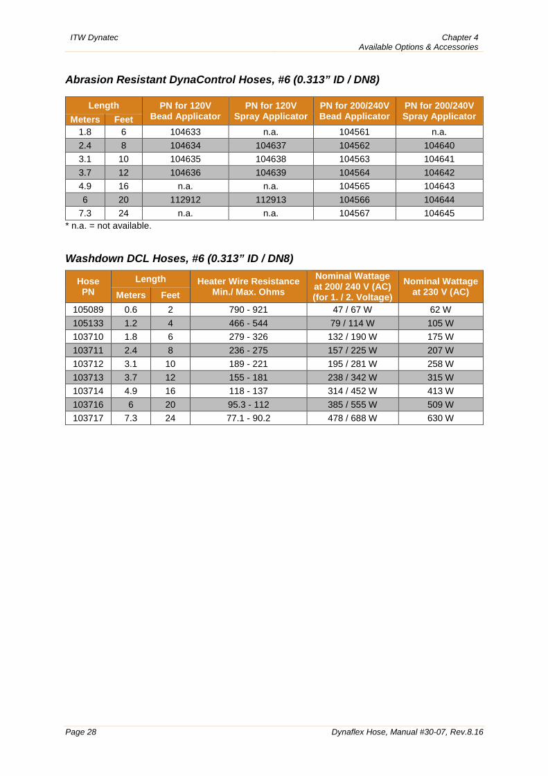
Abrasion Resistant DynaControl Hoses, #6 (0.313” ID / DN8)
Length PN for 120V Bead Applicator
PN for 120V Spray Applicator
PN for 200/240V Bead Applicator
PN for 200/240V Spray Applicator Meters Feet
1.8 6 104633 n.a. 104561 n.a. 2.4 8 104634 104637 104562 104640 3.1 10 104635 104638 104563 104641 3.7 12 104636 104639 104564 104642 4.9 16 n.a. n.a. 104565 104643 6 20 112912 112913 104566 104644
7.3 24 n.a. n.a. 104567 104645 * n.a. = not available. Washdown DCL Hoses, #6 (0.313” ID / DN8)
Hose PN
Length Heater Wire Resistance Min./ Max. Ohms
Nominal Wattage at 200/ 240 V (AC) (for 1. / 2. Voltage)
Nominal Wattage at 230 V (AC) Meters Feet
105089 0.6 2 790 - 921 47 / 67 W 62 W 105133 1.2 4 466 - 544 79 / 114 W 105 W 103710 1.8 6 279 - 326 132 / 190 W 175 W 103711 2.4 8 236 - 275 157 / 225 W 207 W 103712 3.1 10 189 - 221 195 / 281 W 258 W 103713 3.7 12 155 - 181 238 / 342 W 315 W 103714 4.9 16 118 - 137 314 / 452 W 413 W 103716 6 20 95.3 - 112 385 / 555 W 509 W 103717 7.3 24 77.1 - 90.2 478 / 688 W 630 W
Chapter 4 Available Options & Accessories
ITW Dynatec
Dynaflex Hose, Manual #30-07, Rev.8.16 Page 29
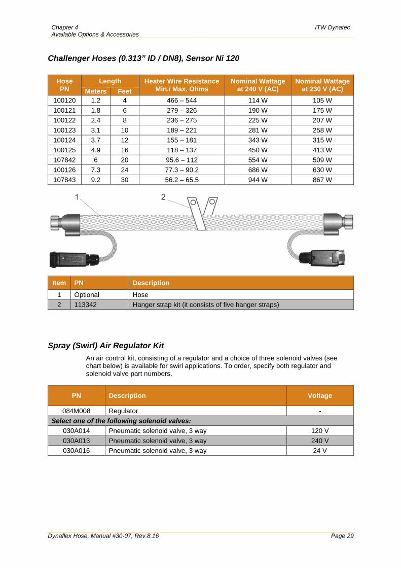
Challenger Hoses (0.313” ID / DN8), Sensor Ni 120
Hose PN
Length Heater Wire Resistance Min./ Max. Ohms
Nominal Wattage at 240 V (AC)
Nominal Wattage at 230 V (AC) Meters Feet
100120 1.2 4 466 – 544 114 W 105 W 100121 1.8 6 279 – 326 190 W 175 W 100122 2.4 8 236 – 275 225 W 207 W 100123 3.1 10 189 – 221 281 W 258 W 100124 3.7 12 155 – 181 343 W 315 W 100125 4.9 16 118 – 137 450 W 413 W 107842 6 20 95.6 – 112 554 W 509 W 100126 7.3 24 77.3 – 90.2 686 W 630 W 107843 9.2 30 56.2 – 65.5 944 W 867 W
Item PN Description
1 Optional Hose 2 113342 Hanger strap kit (it consists of five hanger straps)
Spray (Swirl) Air Regulator Kit
An air control kit, consisting of a regulator and a choice of three solenoid valves (see chart below) is available for swirl applications. To order, specify both regulator and solenoid valve part numbers.
PN Description Voltage
084M008 Regulator - Select one of the following solenoid valves:
030A014 Pneumatic solenoid valve, 3 way 120 V 030A013 Pneumatic solenoid valve, 3 way 240 V 030A016 Pneumatic solenoid valve, 3 way 24 V
ITW Dynatec Chapter 4 Available Options & Accessories
Page 30 Dynaflex Hose, Manual #30-07, Rev.8.16
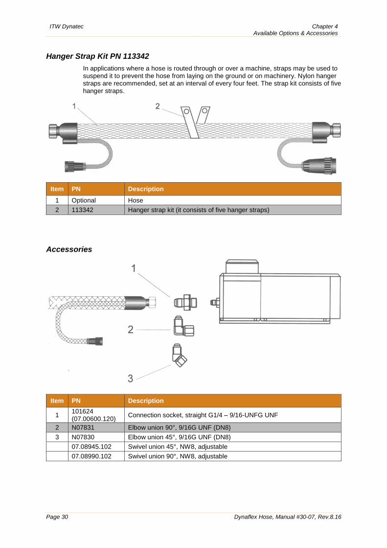
Hanger Strap Kit PN 113342
In applications where a hose is routed through or over a machine, straps may be used to suspend it to prevent the hose from laying on the ground or on machinery. Nylon hanger straps are recommended, set at an interval of every four feet. The strap kit consists of five hanger straps.
Item PN Description
1 Optional Hose 2 113342 Hanger strap kit (it consists of five hanger straps)
Accessories
Item PN Description
1 101624 (07.00600.120) Connection socket, straight G1/4 – 9/16-UNFG UNF
2 N07831 Elbow union 90°, 9/16G UNF (DN8) 3 N07830 Elbow union 45°, 9/16G UNF (DN8) 07.08945.102 Swivel union 45°, NW8, adjustable 07.08990.102 Swivel union 90°, NW8, adjustable
Chapter 5 Schematics
ITW Dynatec
Dynaflex Hose, Manual #30-07, Rev.8.16 Page 31
Chapter 5 Schematics
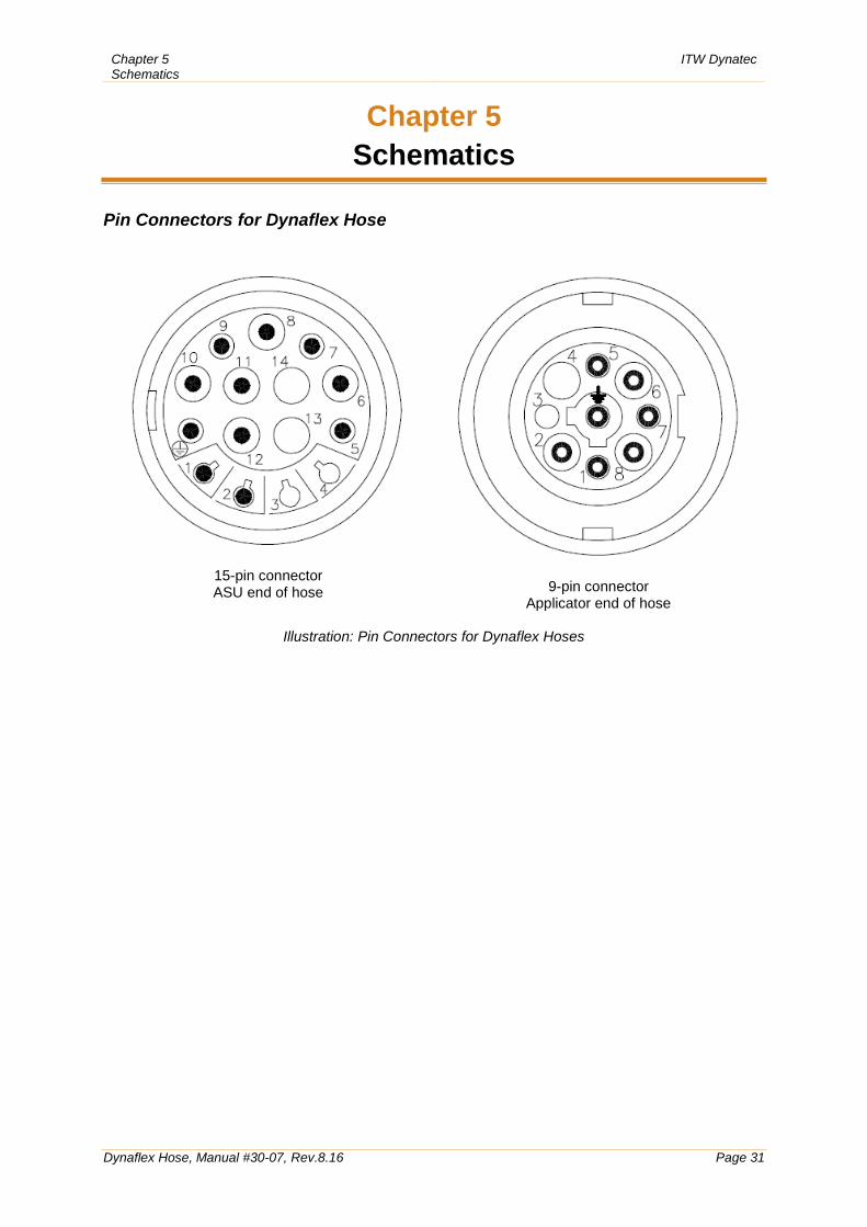
Pin Connectors for Dynaflex Hose
15-pin connector ASU end of hose
9-pin connector Applicator end of hose
Illustration: Pin Connectors for Dynaflex Hoses
ITW Dynatec Chapter 5 Schematics
Page 32 Dynaflex Hose, Manual #30-07, Rev.8.16
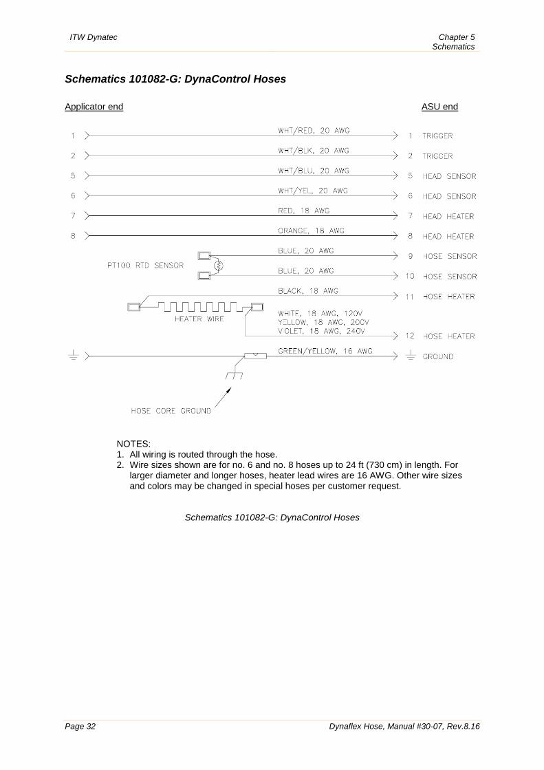
Schematics 101082-G: DynaControl Hoses Applicator end ASU end
NOTES: 1. All wiring is routed through the hose. 2. Wire sizes shown are for no. 6 and no. 8 hoses up to 24 ft (730 cm) in length. For
larger diameter and longer hoses, heater lead wires are 16 AWG. Other wire sizes and colors may be changed in special hoses per customer request.
Schematics 101082-G: DynaControl Hoses
Chapter 5 Schematics
ITW Dynatec
Dynaflex Hose, Manual #30-07, Rev.8.16 Page 33
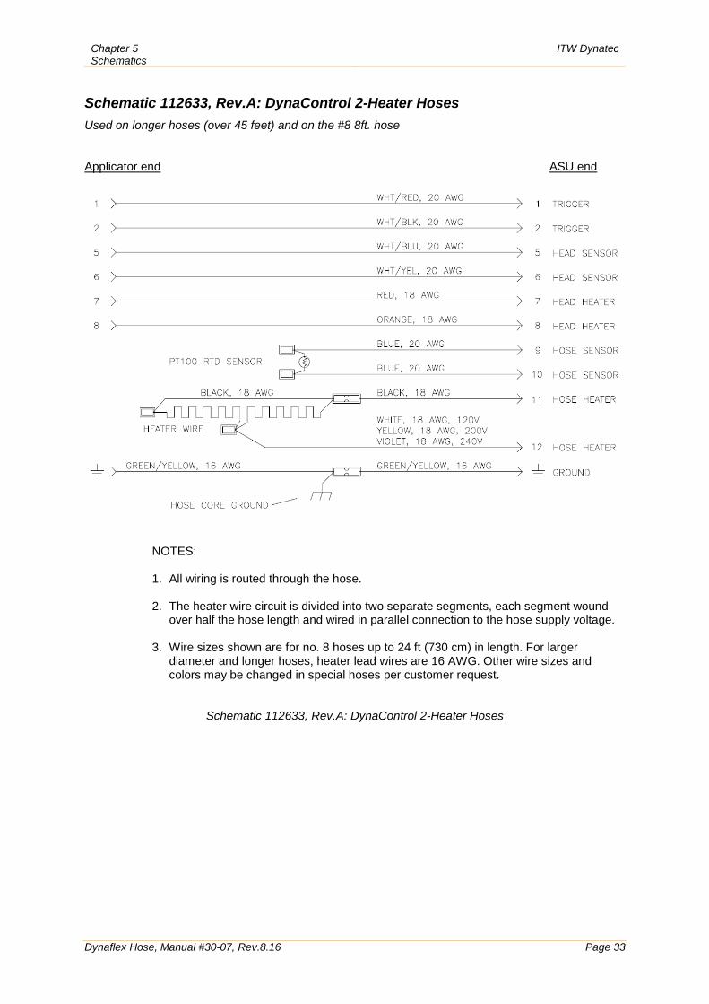
Schematic 112633, Rev.A: DynaControl 2-Heater Hoses Used on longer hoses (over 45 feet) and on the #8 8ft. hose Applicator end ASU end
NOTES: 1. All wiring is routed through the hose.
2. The heater wire circuit is divided into two separate segments, each segment wound
over half the hose length and wired in parallel connection to the hose supply voltage.
3. Wire sizes shown are for no. 8 hoses up to 24 ft (730 cm) in length. For larger diameter and longer hoses, heater lead wires are 16 AWG. Other wire sizes and colors may be changed in special hoses per customer request.
Schematic 112633, Rev.A: DynaControl 2-Heater Hoses
ITW Dynatec Chapter 5 Schematics
Page 34 Dynaflex Hose, Manual #30-07, Rev.8.16
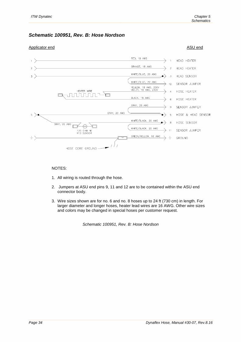
Schematic 100951, Rev. B: Hose Nordson Applicator end ASU end
NOTES: 1. All wiring is routed through the hose.
2. Jumpers at ASU end pins 9, 11 and 12 are to be contained within the ASU end
connector body.
3. Wire sizes shown are for no. 6 and no. 8 hoses up to 24 ft (730 cm) in length. For larger diameter and longer hoses, heater lead wires are 16 AWG. Other wire sizes and colors may be changed in special hoses per customer request.
Schematic 100951, Rev. B: Hose Nordson

Chapter 5 Schematics
ITW Dynatec
Dynaflex Hose, Manual #30-07, Rev.8.16 Page 35
This page intentionally left blank.
ITW Dynatec Chapter 5 Schematics
Page 36 Dynaflex Hose, Manual #30-07, Rev.8.16
ITW Dynatec Service Parts and Technical Service:
AMERICAS
EUROPE, MIDDLE EAST & AFRICA
ASIA PACIFIC
ITW Dynatec 31 Volunteer Drive Hendersonville, TN 37075 USA Tel. +1.615.824.3634 [email protected] [email protected]
ITW Dynatec Industriestrasse 28 40822 Mettmann Germany Tel. +49.2104.915.0 [email protected] [email protected]
ITW Dynatec Unit2, B1 Building No.9 Weixin Road SIP, Suzhou, 215122 China Tel. +86.512.6289.0620 [email protected] [email protected]
ITW Dynatec Tsukimura Building 5th Floor 26-11, Nishikamata 7-chome Ota-ku, Tokyo 144-0051, Japan Tel. +81.3.5703.5501 [email protected] [email protected]


![Floor FloorPlus Loft - Pandomo · 2017-09-12 · 3! panDOMO Floor/FloorPlus Loft pandomo® FLOOR [engl.]: Boden, Etage, Stockwerk PLUS [lat.] mehr, viel PLUS [lat.] more, comp. to](https://img.pdfslide.org/doc/110x75/5fa6ea1c954bf83db806da32/floor-floorplus-loft-pandomo-2017-09-12-3-pandomo-floorfloorplus-loft-pandomo.jpg)