Embed Size (px)
Citation preview
2088
193-
Ed.0
3/20
11-1
0-D
DD
Wilo TOP-S, TOP-Z
Installation and operating instructions
Notice de montage et de mise en service
Instrucciones de instalación y funcionamiento
Umschlag_Einzelseiten_Layout 1 15.12.11 08:49 Seite 2
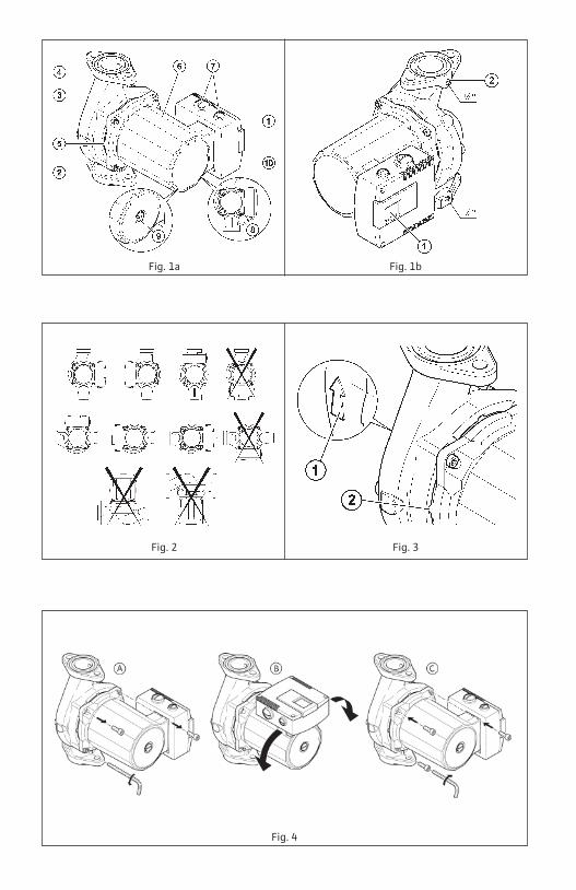
Fig. 1a
Fig. 2
Fig. 1b
Fig. 3
Fig. 4
Umschlag_Einzelseiten_Layout 1 05.12.11 11:14 Seite 3
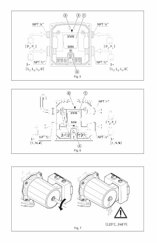
Fig. 5
Fig. 6
Fig. 7
threat of electrocution!
Umschlag_Einzelseiten_Layout 1 05.12.11 11:14 Seite 5
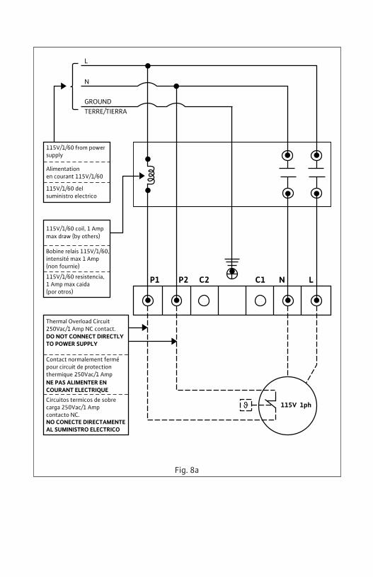
115V 1ph
P1 P2 C2 C1 N L
115V/1/60 from power
Alimentationen courant 115V/1/60
115V/1/60 delsuministro electrico
supply
Thermal Overload Circuit250Vac/1 Amp NC contact.
Contact normalement fermépour circuit de protection thermique 250Vac/1 Amp
Circuitos termicos de sobrecarga 250Vac/1 Ampcontacto NC.
DO NOT CONNECT DIRECTLY
NO CONECTE DIRECTAMENTEAL SUMINISTRO ELECTRICO
NE PAS ALIMENTER ENCOURANT ELECTRIQUE
TO POWER SUPPLY
GROUNDTERRE/TIERRA
L
N
115V/1/60 coil, 1 Amp
115V/1/60 resistencia,1 Amp max caida(por otros)
max draw (by others)
Bobine relais 115V/1/60,intensité max 1 Amp(non fournie)
Fig. 8a
Umschlag_Einzelseiten_Layout 1 05.12.11 11:14 Seite 4
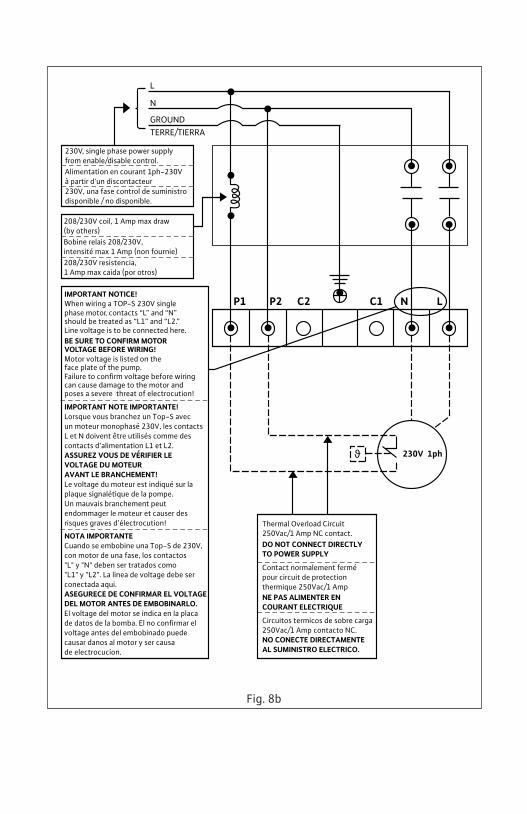
230V 1ph
P1 P2 C2 C1 N L
GROUNDTERRE/TIERRA
L
N
230V, single phase power supplyfrom enable/disable control. Alimentation en courant 1ph-230Và partir d'un discontacteur230V, una fase control de suministrodisponible / no disponible.
208/230V coil, 1 Amp max draw(by others) Bobine relais 208/230V, intensité max 1 Amp (non fournie) 208/230V resistencia,1 Amp max caida (por otros)
IMPORTANT NOTICE!
IMPORTANT NOTE IMPORTANTE!Lorsque vous branchez un Top-S avec un moteur monophasé 230V, les contactsL et N doivent être utilisés comme des contacts d’alimentation L1 et L2. ASSUREZ VOUS DE VÉRIFIER LE VOLTAGE DU MOTEUR AVANT LE BRANCHEMENT!Le voltage du moteur est indiqué sur la plaque signalétique de la pompe. Un mauvais branchement peut endommager le moteur et causer des risques graves d’électrocution!
NOTA IMPORTANTECuando se embobine una Top-S de 230V,con motor de una fase, los contactos"L" y "N" deben ser tratados como "L1" y "L2". La linea de voltage debe serconectada aqui.ASEGURECE DE CONFIRMAR EL VOLTAGEDEL MOTOR ANTES DE EMBOBINARLO.El voltage del motor se indica en la placade datos de la bomba. El no confirmar elvoltage antes del embobinado puedecausar danos al motor y ser causade electrocucion.
phase motor, contacts “L” and “N” When wiring a TOP-S 230V single
should be treated as “L1” and “L2.” Line voltage is to be connected here. BE SURE TO CONFIRM MOTOR VOLTAGE BEFORE WIRING! Motor voltage is listed on the face plate of the pump.Failure to confirm voltage before wiring can cause damage to the motor and poses a severe threat of electrocution!
Thermal Overload Circuit
Circuitos termicos de sobre carga250Vac/1 Amp contacto NC.NO CONECTE DIRECTAMENTEAL SUMINISTRO ELECTRICO.
Contact normalement fermépour circuit de protection thermique 250Vac/1 Amp
250Vac/1 Amp NC contact.DO NOT CONNECT DIRECTLY
NE PAS ALIMENTER ENCOURANT ELECTRIQUE
TO POWER SUPPLY
Fig. 8b
Umschlag_Einzelseiten_Layout 1 05.12.11 11:14 Seite 6
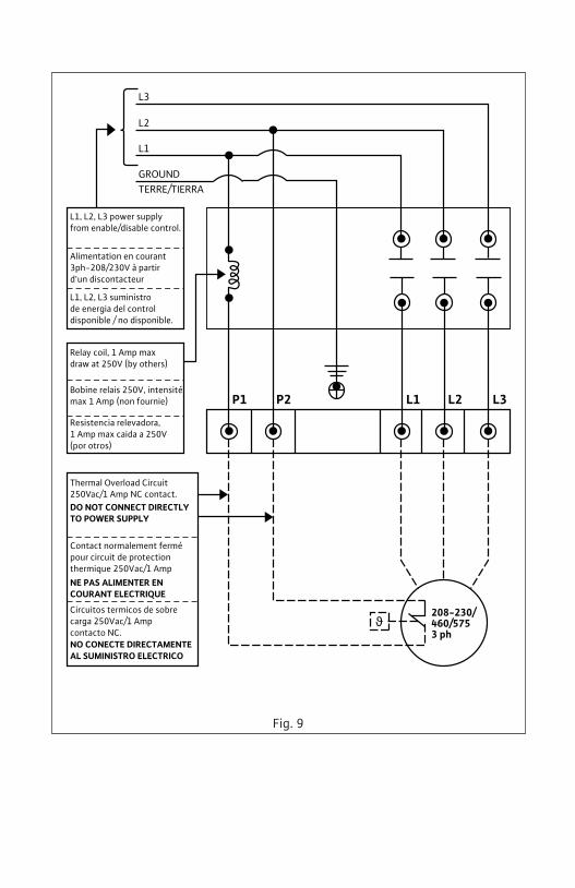
208-230/460/5753 ph
P1 P2 L1 L2 L3
GROUNDTERRE/TIERRA
L3
L2
L1
L1, L2, L3 power supply
L1, L2, L3 suministrode energia del controldisponible / no disponible.
Alimentation en courant3ph-208/230V à partird'un discontacteur
from enable/disable control.
Relay coil, 1 Amp max draw at 250V (by others)
Bobine relais 250V, intensitémax 1 Amp (non fournie)
Resistencia relevadora,1 Amp max caida a 250V(por otros)
Thermal Overload Circuit
Circuitos termicos de sobrecarga 250Vac/1 Ampcontacto NC.
NE PAS ALIMENTER ENCOURANT ELECTRIQUE
Contact normalement fermépour circuit de protection thermique 250Vac/1 Amp
250Vac/1 Amp NC contact.DO NOT CONNECT DIRECTLY TO POWER SUPPLY
NO CONECTE DIRECTAMENTEAL SUMINISTRO ELECTRICO
Fig. 9
Umschlag_Einzelseiten_Layout 1 05.12.11 11:14 Seite 7
Table of contents page1 General . . . . . . . . . . . . . . . . . . . . . . . . . . . . . . . . . . . . . . . . . . . . . . . . . . . . . . . . . . . . . . . . . . . . . . . . . . 32 Safety . . . . . . . . . . . . . . . . . . . . . . . . . . . . . . . . . . . . . . . . . . . . . . . . . . . . . . . . . . . . . . . . . . . . . . . . . . . 33 Transport and interim storage . . . . . . . . . . . . . . . . . . . . . . . . . . . . . . . . . . . . . . . . . . . . . . . . . . . . . 44 Intended use (Application) . . . . . . . . . . . . . . . . . . . . . . . . . . . . . . . . . . . . . . . . . . . . . . . . . . . . . . . . 45 Technical data . . . . . . . . . . . . . . . . . . . . . . . . . . . . . . . . . . . . . . . . . . . . . . . . . . . . . . . . . . . . . . . . . . . . 56 Description and function . . . . . . . . . . . . . . . . . . . . . . . . . . . . . . . . . . . . . . . . . . . . . . . . . . . . . . . . . . 67 Installation and electrical connection . . . . . . . . . . . . . . . . . . . . . . . . . . . . . . . . . . . . . . . . . . . . . . . 68 Start up . . . . . . . . . . . . . . . . . . . . . . . . . . . . . . . . . . . . . . . . . . . . . . . . . . . . . . . . . . . . . . . . . . . . . . . . . 89 Maintenance / Service . . . . . . . . . . . . . . . . . . . . . . . . . . . . . . . . . . . . . . . . . . . . . . . . . . . . . . . . . . . . . 9
10 Faults, causes and remedies . . . . . . . . . . . . . . . . . . . . . . . . . . . . . . . . . . . . . . . . . . . . . . . . . . . . . . .1011 Spare parts . . . . . . . . . . . . . . . . . . . . . . . . . . . . . . . . . . . . . . . . . . . . . . . . . . . . . . . . . . . . . . . . . . . . . .12
Table des matières page1 Généralités . . . . . . . . . . . . . . . . . . . . . . . . . . . . . . . . . . . . . . . . . . . . . . . . . . . . . . . . . . . . . . . . . . . . . .132 Sécurité . . . . . . . . . . . . . . . . . . . . . . . . . . . . . . . . . . . . . . . . . . . . . . . . . . . . . . . . . . . . . . . . . . . . . . . . .133 Transport et stockage avant utilisation . . . . . . . . . . . . . . . . . . . . . . . . . . . . . . . . . . . . . . . . . . . . .144 Utilisation prévue (application) . . . . . . . . . . . . . . . . . . . . . . . . . . . . . . . . . . . . . . . . . . . . . . . . . . . .145 Données techniques . . . . . . . . . . . . . . . . . . . . . . . . . . . . . . . . . . . . . . . . . . . . . . . . . . . . . . . . . . . . . .156 Description et fonctionnement . . . . . . . . . . . . . . . . . . . . . . . . . . . . . . . . . . . . . . . . . . . . . . . . . . . .167 Installation et raccordement électrique . . . . . . . . . . . . . . . . . . . . . . . . . . . . . . . . . . . . . . . . . . . . .168 Démarrage . . . . . . . . . . . . . . . . . . . . . . . . . . . . . . . . . . . . . . . . . . . . . . . . . . . . . . . . . . . . . . . . . . . . . . .199 Entretien / Service . . . . . . . . . . . . . . . . . . . . . . . . . . . . . . . . . . . . . . . . . . . . . . . . . . . . . . . . . . . . . . . .20
10 Défauts, causes et remèdes . . . . . . . . . . . . . . . . . . . . . . . . . . . . . . . . . . . . . . . . . . . . . . . . . . . . . . .2011 Pièces de rechange . . . . . . . . . . . . . . . . . . . . . . . . . . . . . . . . . . . . . . . . . . . . . . . . . . . . . . . . . . . . . . .23
Contenido página1 Generalidades . . . . . . . . . . . . . . . . . . . . . . . . . . . . . . . . . . . . . . . . . . . . . . . . . . . . . . . . . . . . . . . . . . . .242 Seguridad . . . . . . . . . . . . . . . . . . . . . . . . . . . . . . . . . . . . . . . . . . . . . . . . . . . . . . . . . . . . . . . . . . . . . . . .243 Transporte y almacenaje . . . . . . . . . . . . . . . . . . . . . . . . . . . . . . . . . . . . . . . . . . . . . . . . . . . . . . . . . .254 Uso previsto (aplicación) . . . . . . . . . . . . . . . . . . . . . . . . . . . . . . . . . . . . . . . . . . . . . . . . . . . . . . . . . .255 Datos técnicos . . . . . . . . . . . . . . . . . . . . . . . . . . . . . . . . . . . . . . . . . . . . . . . . . . . . . . . . . . . . . . . . . . .266 Descripción y funcionamiento . . . . . . . . . . . . . . . . . . . . . . . . . . . . . . . . . . . . . . . . . . . . . . . . . . . . .277 Instalación y conexión eléctrica . . . . . . . . . . . . . . . . . . . . . . . . . . . . . . . . . . . . . . . . . . . . . . . . . . . .278 Puesta en marcha . . . . . . . . . . . . . . . . . . . . . . . . . . . . . . . . . . . . . . . . . . . . . . . . . . . . . . . . . . . . . . . .309 Mantenimiento / Reparación . . . . . . . . . . . . . . . . . . . . . . . . . . . . . . . . . . . . . . . . . . . . . . . . . . . . . . .31
10 Averías, causas y soluciones . . . . . . . . . . . . . . . . . . . . . . . . . . . . . . . . . . . . . . . . . . . . . . . . . . . . . . .3111 Repuestos . . . . . . . . . . . . . . . . . . . . . . . . . . . . . . . . . . . . . . . . . . . . . . . . . . . . . . . . . . . . . . . . . . . . . . .34
01-12_2058935_NAMEX_USA_1b12.qxd 05.12.11 11:25 Seite 1

01-12_2058935_NAMEX_USA_1b12.qxd 15.12.11 12:27 Seite 2
1 General1.1 About this documentThese Installation and Operating Instructions form an integral part of the product. They must bekept close to the product and in readiness whenever required. Precise observance of these in-structions is a pre-condition for use of the product for the intended purpose and for its correctoperation.These Installation and Operating Instructions conform to the relevant version of the equipmentand the underlying safety standards valid at the time of going to press.
2 SafetyThese instructions contain important information which must be followed when installing andoperating the pump. It is therefore imperative that they are read by both the installer and theoperator before the circulator is installed or started up.Both the general safety instructions in the ‘Safety precautions’ section and those in subsequentsections indicated by danger symbols should be carefully observed.
2.1 Symbols and signal words used in these operating instructionsSymbols:
General Safety symbol
Hazards from electrical causes
Signal words:
A notice with useful information for the user in relation to the product. It attends theuser to possible problems.
2.2 Qualified PersonnelThe personnel installing the pump must have the appropriate qualifications for this work.
2.3 Risks incurred by failure to comply with the safety precautionsFailure to comply with the safety precautions could result in personal injury or damage to thepump or installation. Failure to comply with the safety precautions could invalidate warrantyand/or damage claims.In particular, failure to comply with these safety precautions could increase the possibility of thefollowing risks:x the failure of important parts of the pump or installation,x personal injury due to electrical and mechanical causes,x material damage.
NOTE!
ENGLISH
3
DANGER! Imminently hazardous situation.Will result in death or serious injury if not avoided.
WARNING! The user can be exposed to (severe) injury. 'Warning' refers to the risk ofharm to the user when the user is neglecting the procedure.
CAUTION! The product is at risk of damage. 'Caution' refers to the product when theuser is neglecting the procedures.
01-12_2058935_NAMEX_USA_1b12.qxd 05.12.11 11:25 Seite 3
2.4 Safety precautions for the operatorExisting regulations for the prevention of accidents must be observed.National Electrical Codes, local codes and regulations must be followed.
2.5 Safety precautions for inspection and installationThe operator must ensure that all inspection and installation work is carried out by authorizedand qualified specialists who have carefully reviewed these instructions. Work on the pump/unit must be carried out only with the pump disconnected from the powersupply and at complete standstill.
2.6 Unauthorized alterations and manufacture of spare partsAlterations to the pump or installation may only be carried out with the manufacturer's consent.The use of original spare parts and accessories authorized by the manufacturer will ensure sa-fety. The use of any other parts may invalidate claims relieving the liability of the manufacturerfor any consequences.
2.7 Improper useThe operational safety of the pump or installation supplied can only be guaranteed if it is usedin accordance with paragraph 4 of the operating instructions. The limits given in the catalogueor data sheet must under no circumstances be exceeded.
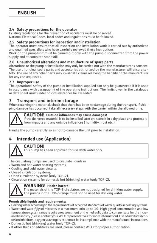
3 Transport and interim storageWhen receiving the material, check that there has been no damage during the transport. If ship-ping damage has occurred, take all necessary steps with the carrier within the allowed time.
Handle the pump carefully so as not to damage the unit prior to installation.
4 Intended use (Application)
The circulating pumps are used to circulate liquids inx Warm and hot water heating systems,x Cooling and cold water circuits,x Closed circulation systems,x Open circulation systems (only TOP-Z),x Circulation systems for domestic hot (drinking) water (only TOP-Z).
Permissible liquids and requirements:x Heating water according to the requirements of accepted standards of water quality in heating systems.x Water and water/glycol mixtures in a maximum ratio up to 1:1. High glycol concentration and lowtemperature systems may require a reassessment of the hydraulic data to compensate for the incre-ased viscosity (please contact your WILO representatives for more information). Use of additives (cor-rosion inhibitors, oxygen scavengers etc.) must be in compliance with the manufacturer instructions.
x Domestic hot (drinking) water (only TOP-Z).x If other fluids or additives are used, please contact WILO for proper authorization.
ENGLISH
4
CAUTION! Outside influences may cause damages!If the delivered material is to be installed later on, store it in a dry place and protect itfrom impacts and any outside influences ( humidity, frost etc.).
WARNING! Health hazard!The materials of the TOP-S circulators are not designed for drinking water supply.The pumps in the TOP-S range must not be used for drinking water.
CAUTION!This pump has been approved for use with water only.
01-12_2058935_NAMEX_USA_1b12.qxd 05.12.11 11:25 Seite 4
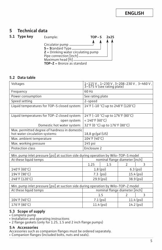
5 Technical data5.1 Type key
5.2 Data table
5.3 Scope of supply x Complete pumpx Installation and operating instructionsx 2 flange gaskets (only for 1.25, 1.5 and 2 inch flange pumps)
5.4 Accessories Accessories such as companion flanges must be ordered separately.x Companion flanges (included bolts, nuts and seals).
ENGLISH
5
Voltages 1~115 V , 1~230 V , 3~208-230 V , 3~460 V ,3~575 V (see rating plate)Frequency 60 HzPower consumption See rating plateSpeed setting 2-speed Liquid temperatures for TOP-S closed system: 14°F (-10 °C) up to 248°F (120°C)
Liquid temperatures for TOP-Z closed system: 14°F (-10 °C) up to 176°F (80°C)open system: < 140°F (60°C)
Domestic hot water system: 32°F (0 °C) up to 176°F (80°C)Max. permitted degree of hardness in domestichot water circulation systems: 18,8 gr/gal (US)Max. ambient temperature 104°F (40°C)Max. working pressure 145 psi Protection class Enclosure 2
Min. pump inlet pressure [psi] at suction side during operation by Wilo-TOP-S modelAt these liquid temps nominal flange diameter [inch]
1.25 1.5 2 3140°F (60°C) 1.8 (psi) 6.3 (psi)194°F (90°C) 7.3 (psi) 15.4 (psi)248°F (120°C) 29.9 (psi) 38.9 (psi)
Min. pump inlet pressure [psi] at suction side during operation by Wilo-TOP-Z modelAt these liquid temps nominal flange diameter [inch]
1.5 2 3104°F (40°C) 7.1 (psi) 11.4 (psi)176°F (80°C) 11.4 (psi) 14.2 (psi)
Example: TOP- S 2x25
Circulator pumpS= Standard TypeZ = Drinking water circulating pumpPipe connection [inch]Maximum head [ft]TOP-Z = Bronze as standard
01-12_2058935_NAMEX_USA_1b12.qxd 05.12.11 11:25 Seite 5
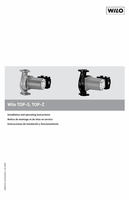
6 Description and function6.1 Product description (see Fig. 1a)1 Terminal box 6 Motor housing2 Suction side 7 Cable entry3 Pump housing 8 Capacitor (only for single phase pumps)4 Discharge side 9 Venting plug (only on some types)5 Condensate outlet 10 Rating plate
6.2 Design of pump and motorThis wet rotor pump is designed to have all rotating parts surrounded by the liquid being pumped andis suitable for single or three phase operation (see pump rating plate). A shaft seal, which would be sub-ject to wear and maintenance is not required. Depending on the design of the pump, the system fluidlubricates the sleeve bearings and cools both bearings and motor. The pump is maintenance-free andrequires no further maintenance after the air bleeding procedure during the initial start-up (no afterstart-up maintenance). The Wilo model TOP-Z is specially designed for use in conjunction with drinking water circulation sy-stems. Thanks to its design and materials used in its construction the pump is resistant to corrosionfrom elements in domestic hot water ( drinking water). All materials coming in contact with the deli-very medium are NSF/ANSI 61 certified.
6.3 Functions Speed setting of TOP-S.../TOP-Z... pumps (Fig. 5 and Fig.6)The required speed of the pump can be adjusted manually in 2 positions (Max. and Min.) by mo-ving the switch connector to the relevant socket. Procedure see Chapter “8.2 speed setting”.Ensure power is turned off prior to changing speeds!
7 Installation and electrical connectionInstallation and electrical work in compliance with any local codes and by quali-fied personnel only!
7.1 Installationx The pump must be installed in a dry, well ventilated and frost-free place.
x The pump must be installed in an easily accessible position to facilitate inspection or replacement.x The pump should never be located at the lowest point of the piping system, where dirt and se-diment collect. Nor should it be located at the highest point of the piping system, where air ac-cumulates. Please ensure at least a minimum of three pipe diameters of straight on the suc-tion side of the pump.
ENGLISH
6
WARNING! Bodily injury!Existing regulations for the prevention of accidents must be observed.
WARNING! Electrical shock hazard!Dangers caused by electrical energy must be excluded. National Electrical Codes, local codes and regulations must be followed.
CAUTION! Possible damage of the pump!Foreign materials such as dirt and solder can effect the pump operation.x It is recommended that any welding and soldering work be done before installingthe pump.
x Thoroughly flush the system prior to installing and operating the pump.x Foreign material in the system resulting from construction may damage the pumpand is not warrantable.
01-12_2058935_NAMEX_USA_1b12.qxd 05.12.11 11:25 Seite 6
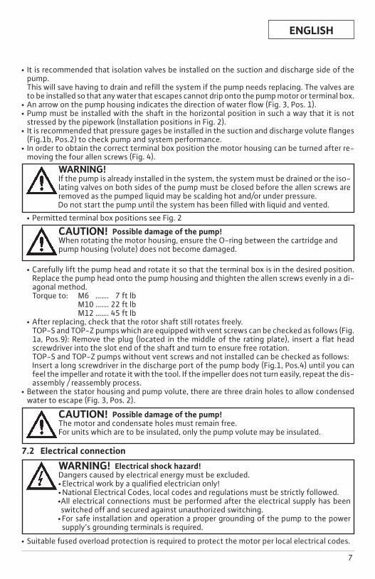
x It is recommended that isolation valves be installed on the suction and discharge side of thepump. This will save having to drain and refill the system if the pump needs replacing. The valves areto be installed so that any water that escapes cannot drip onto the pump motor or terminal box.
x An arrow on the pump housing indicates the direction of water flow (Fig. 3, Pos. 1). x Pump must be installed with the shaft in the horizontal position in such a way that it is notstressed by the pipework (Installation positions in Fig. 2).
x It is recommended that pressure gages be installed in the suction and discharge volute flanges(Fig.1b, Pos.2) to check pump and system performance.
x In order to obtain the correct terminal box position the motor housing can be turned after re-moving the four allen screws (Fig. 4).
x Permitted terminal box positions see Fig. 2
x Carefully lift the pump head and rotate it so that the terminal box is in the desired position.Replace the pump head onto the pump housing and thighten the allen screws evenly in a di-agonal method.Torque to: M6 ……. 17 ft lb
M10 ……. 22 ft lbM12 ……. 45 ft lb
x After replacing, check that the rotor shaft still rotates freely.TOP-S and TOP-Z pumps which are equipped with vent screws can be checked as follows (Fig.1a, Pos.9): Remove the plug (located in the middle of the rating plate), insert a flat headscrewdriver into the slot end of the shaft and turn to ensure free rotation.TOP-S and TOP-Z pumps without vent screws and not installed can be checked as follows:Insert a long screwdriver in the discharge port of the pump body (Fig.1, Pos.4) until you canfeel the impeller and rotate it with the tool. If the impeller does not turn easily, repeat the dis -assembly / reassembly process.
x Between the stator housing and pump volute, there are three drain holes to allow condensedwater to escape (Fig. 3, Pos. 2).
7.2 Electrical connection
x Suitable fused overload protection is required to protect the motor per local electrical codes.
ENGLISH
7
WARNING!If the pump is already installed in the system, the system must be drained or the iso-lating valves on both sides of the pump must be closed before the allen screws areremoved as the pumped liquid may be scalding hot and/or under pressure. Do not start the pump until the system has been filled with liquid and vented.
CAUTION! Possible damage of the pump!When rotating the motor housing, ensure the O-ring between the cartridge andpump housing (volute) does not become damaged.
CAUTION! Possible damage of the pump!The motor and condensate holes must remain free.For units which are to be insulated, only the pump volute may be insulated.
WARNING! Electrical shock hazard!Dangers caused by electrical energy must be excluded. x Electrical work by a qualified electrician only!x National Electrical Codes, local codes and regulations must be strictly followed.x All electrical connections must be performed after the electrical supply has beenswitched off and secured against unauthorized switching.
x For safe installation and operation a proper grounding of the pump to the powersupply’s grounding terminals is required.
01-12_2058935_NAMEX_USA_1b12.qxd 05.12.11 11:25 Seite 7
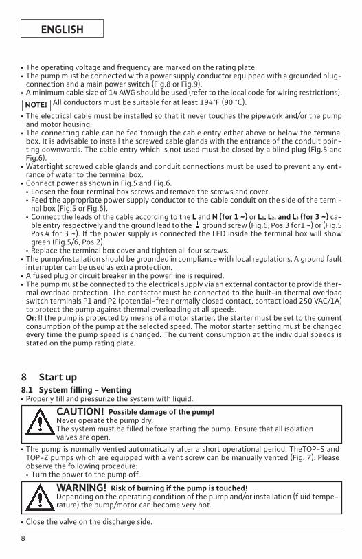
x The operating voltage and frequency are marked on the rating plate.x The pump must be connected with a power supply conductor equipped with a grounded plug-connection and a main power switch (Fig.8 or Fig.9).
x A minimum cable size of 14 AWG should be used (refer to the local code for wiring restrictions).All conductors must be suitable for at least 194°F (90 °C).
x The electrical cable must be installed so that it never touches the pipework and/or the pumpand motor housing.
x The connecting cable can be fed through the cable entry either above or below the terminalbox. It is advisable to install the screwed cable glands with the entrance of the conduit poin-ting downwards. The cable entry which is not used must be closed by a blind plug (Fig.5 andFig.6).
x Watertight screwed cable glands and conduit connections must be used to prevent any ent-rance of water to the terminal box.
x Connect power as shown in Fig.5 and Fig.6.x Loosen the four terminal box screws and remove the screws and cover.x Feed the appropriate power supply conductor to the cable conduit on the side of the termi-nal box (Fig.5 or Fig.6).
x Connect the leads of the cable according to the L and N (for 1 ~) or L1, L2, and L3 (for 3 ~) ca-ble entry respectively and the ground lead to the ground screw (Fig.6, Pos.3 for1 ~) or (Fig.5Pos.4 for 3 ~). If the power supply is connected the LED inside the terminal box will showgreen (Fig.5/6, Pos.2).
x Replace the terminal box cover and tighten all four screws.x The pump/installation should be grounded in compliance with local regulations. A ground faultinterrupter can be used as extra protection.
x A fused plug or circuit breaker in the power line is required.x The pump must be connected to the electrical supply via an external contactor to provide ther-mal overload protection. The contactor must be connected to the built-in thermal overloadswitch terminals P1 and P2 (potential-free normally closed contact, contact load 250 VAC/1A)to protect the pump against thermal overloading at all speeds.Or: If the pump is protected by means of a motor starter, the starter must be set to the currentconsumption of the pump at the selected speed. The motor starter setting must be changedevery time the pump speed is changed. The current consumption at the individual speeds isstated on the pump rating plate.
8 Start up8.1 System filling - Ventingx Properly fill and pressurize the system with liquid.
x The pump is normally vented automatically after a short operational period. TheTOP-S andTOP-Z pumps which are equipped with a vent screw can be manually vented (Fig. 7). Pleaseobserve the following procedure:x Turn the power to the pump off.
x Close the valve on the discharge side.
NOTE!
ENGLISH
8
CAUTION! Possible damage of the pump!Never operate the pump dry.The system must be filled before starting the pump. Ensure that all isolation valves are open.
WARNING! Risk of burning if the pump is touched!Depending on the operating condition of the pump and/or installation (fluid tempe-rature) the pump/motor can become very hot.
01-12_2058935_NAMEX_USA_1b12.qxd 15.12.11 08:51 Seite 8
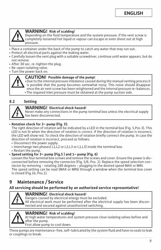
x Place a container under the back of the pump to catch any water that may run out.x Protect all electrical parts against the leaking water.x Carefully loosen the vent plug with a suitable screwdriver, continue until water appears, but donot remove.
x After 30 sec. re-tighten the plug.x Re-open isolating valve.x Turn the power back on.
8.2 Setting
x Rotation check for 3~ pump (Fig. 5): The right direction of rotation will be indicated by a LED in the terminal box (Fig. 5,Pos 3). ThisLED is not lit when the direction of rotation is correct. If the direction of rotation is incorrect,the LED will show red. To check the direction of rotation briefly connect the pump. In case thedirection of rotation is incorrect, proceed as follows:x Disconnect the power supply. x Interchange two phases( L1,L2 or L2,L3 or L1,L3) inside the terminal box.x Restart the pump.
x Speed setting for 3~ pump (Fig.5 ) and 1~ pump (Fig. 6)Loosen the four terminal box screws and remove the screws and cover. Ensure the power is dis -connected before removing the connector (Fig. 5/6, Pos. 1). Replace the speed selection con-nector by removing - rotating 180 degrees - plugging to the desired speed MAX or MIN. The speed setting can be read (MAX or MIN) through a window when the terminal box cover is closed (Fig.1b, Pos.1).
9 Maintenance / ServiceAll servicing should be performed by an authorized service representative!
These pumps are maintenance-free, self-lubricated by the system fluid and have no seals to leakor couplings to break.
ENGLISH
9
WARNING! Risk of scalding!At high water temperatures and system pressure close isolating valves before andafter the pump. First allow pump to cool down.
WARNING! Electrical shock hazard!Never make any connections in the pump terminal box unless the electrical supplyhas been disconnected.
WARNING! Electrical shock hazard!Dangers caused by electrical energy must be excluded. All electrical work must be performed after the electrical supply has been discon-nected and secured against unauthorized switching.
WARNING! Risk of scalding!Depending on the fluid temperature and the system pressure, if the vent screw iscompletely loosened hot liquid or vapour can escape or even shoot out at highpressure.
CAUTION! Possible damage of the pump!x Due to the internal pressure imbalance caused during the manual venting process itis possible that the pump becomes somewhat noisy. This noise should disappearonce the air vent screw has been retightened and the internal pressure re-balances.
x The required inlet pressure must be obtained at the pump suction side.
01-12_2058935_NAMEX_USA_1b12.qxd 05.12.11 11:25 Seite 9
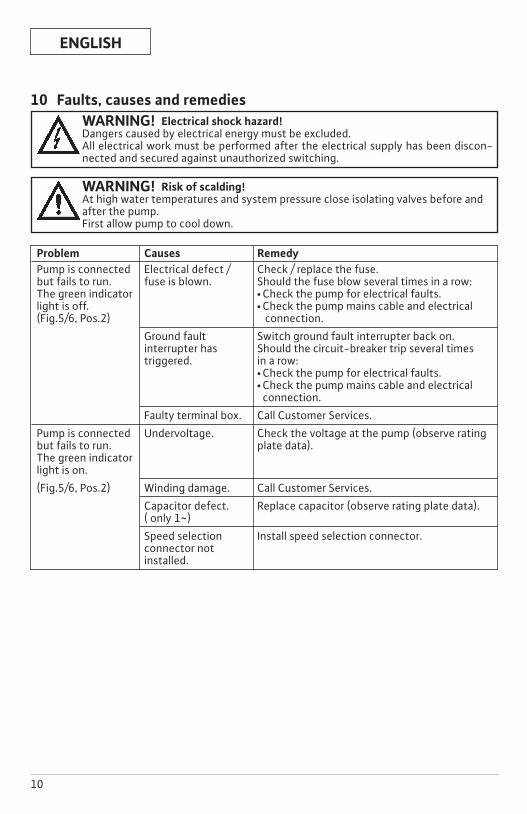
10 Faults, causes and remedies
ENGLISH
10
WARNING! Electrical shock hazard!Dangers caused by electrical energy must be excluded. All electrical work must be performed after the electrical supply has been discon-nected and secured against unauthorized switching.
WARNING! Risk of scalding! At high water temperatures and system pressure close isolating valves before andafter the pump. First allow pump to cool down.
Problem Causes RemedyPump is connected Electrical defect / Check / replace the fuse.but fails to run. fuse is blown. Should the fuse blow several times in a row:The green indicator x Check the pump for electrical faults.light is off. x Check the pump mains cable and electrical (Fig.5/6, Pos.2) connection.
Ground fault Switch ground fault interrupter back on. interrupter has Should the circuit-breaker trip several times triggered. in a row:
x Check the pump for electrical faults.x Check the pump mains cable and electricalconnection.
Faulty terminal box. Call Customer Services.
Pump is connected Undervoltage. Check the voltage at the pump (observe rating but fails to run. plate data).The green indicator light is on.
(Fig.5/6, Pos.2) Winding damage. Call Customer Services.
Capacitor defect. Replace capacitor (observe rating plate data).( only 1~)
Speed selection Install speed selection connector.connector not installed.
01-12_2058935_NAMEX_USA_1b12.qxd 05.12.11 11:25 Seite 10
ENGLISH
11
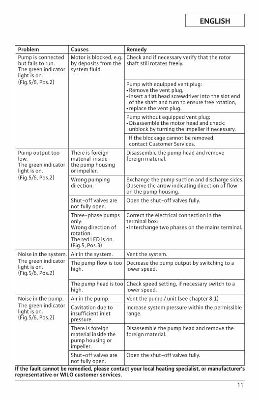
Problem Causes RemedyPump is connected Motor is blocked, e.g. Check and if necessary verify that the rotor but fails to run. by deposits from the shaft still rotates freely. The green indicator system fluid.light is on.(Fig.5/6, Pos.2) Pump with equipped vent plug:
x Remove the vent plug,x insert a flat head screwdriver into the slot endof the shaft and turn to ensure free rotation,
x replace the vent plug.
Pump without equipped vent plug:x Disassemble the motor head and check; unblock by turning the impeller if necessary.
If the blockage cannot be removed, contact Customer Services.
Pump output too There is foreign Disassemble the pump head and remove low. material inside foreign material.The green indicator the pump housinglight is on. or impeller.(Fig.5/6, Pos.2) Wrong pumping Exchange the pump suction and discharge sides.
direction. Observe the arrow indicating direction of flowon the pump housing.
Shut-off valves are Open the shut-off valves fully. not fully open.
Three-phase pumps Correct the electrical connection in the only: terminal box:Wrong direction of x Interchange two phases on the mains terminal.rotation.The red LED is on.(Fig.5, Pos.3)
Noise in the system. Air in the system. Vent the system.The green indicator The pump flow is too Decrease the pump output by switching to alight is on. high. lower speed.(Fig.5/6, Pos.2)
The pump head is too Check speed setting, if necessary switch to a high. lower speed.
Noise in the pump. Air in the pump. Vent the pump / unit (see chapter 8.1)The green indicator Cavitation due to Increase system pressure within the permissible light is on. insufficient inlet range.(Fig.5/6, Pos.2) pressure.
There is foreign Disassemble the pump head and remove the material inside the foreign material.pump housing or impeller.
Shut-off valves are Open the shut-off valves fully. not fully open.
If the fault cannot be remedied, please contact your local heating specialist, or manufacturer'srepresentative or WILO customer services.
01-12_2058935_NAMEX_USA_1b12.qxd 05.12.11 15:18 Seite 11

ENGLISH
12
11 Spare partsAll spare parts must be ordered through your local specialist and/or Wilo Customer Services.In order to avoid returns and incorrect orders, please specify the rating plate data for all orders.
01-12_2058935_NAMEX_USA_1b12.qxd 05.12.11 11:25 Seite 12


![[Marianna Pascal] Say It Better in English Useful(BookZa.org)](https://img.pdfslide.org/doc/110x75/55cf976e550346d03391939a/marianna-pascal-say-it-better-in-english-usefulbookzaorg.jpg)