ABU
S C
ompo
nent
s / A
ABU
S K
ompo
nent
en /
A
Sicherheits-Schleifleitung KBH Safety conductor KBH
Universal-Bauteile Universal components
Schleppleitung Festoon cable system
Elektro-InstallationsmaterialElectric installation material
2 3
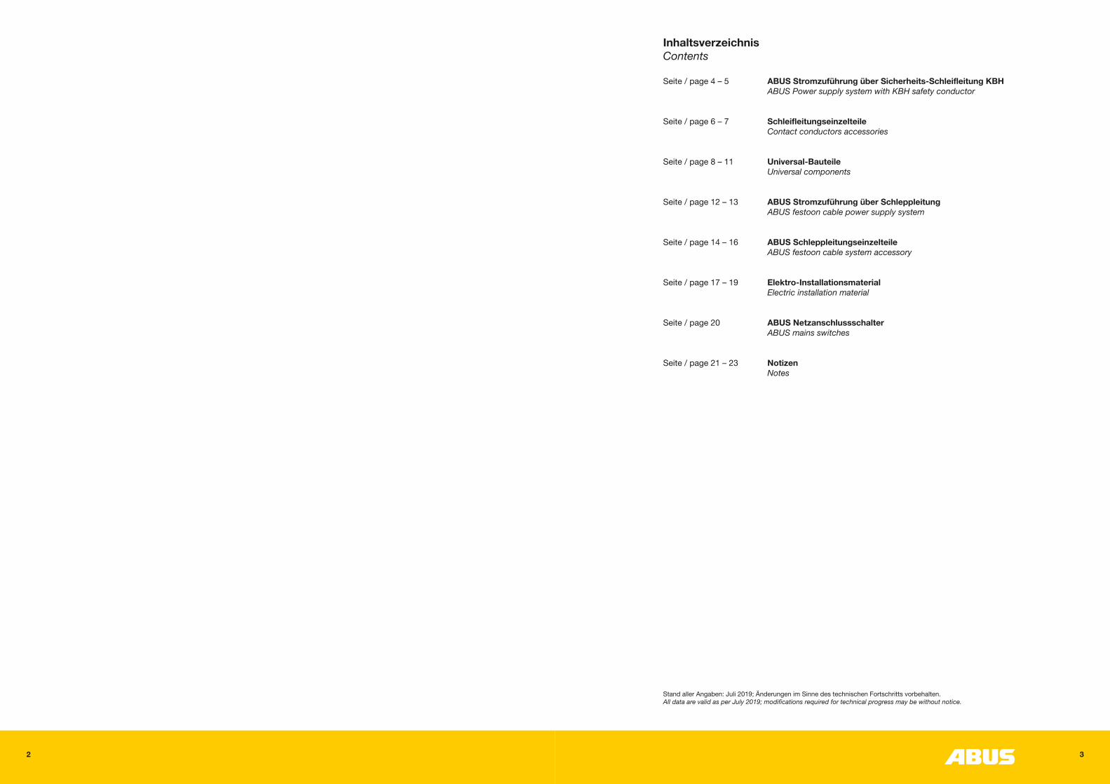
InhaltsverzeichnisContents
Seite / page 4 – 5 ABUS Stromzuführung über Sicherheits-Schleifleitung KBH ABUS Power supply system with KBH safety conductor
Seite / page 6 – 7 Schleifleitungseinzelteile Contact conductors accessories
Seite / page 8 – 11 Universal-Bauteile Universal components
Seite / page 12 – 13 ABUS Stromzuführung über Schleppleitung ABUS festoon cable power supply system
Seite / page 14 – 16 ABUS Schleppleitungseinzelteile ABUS festoon cable system accessory
Seite / page 17 – 19 Elektro-Installationsmaterial Electric installation material
Seite / page 20 ABUS Netzanschlussschalter ABUS mains switches
Seite / page 21 – 23 Notizen Notes
Stand aller Angaben: Juli 2019; Änderungen im Sinne des technischen Fortschritts vorbehalten.All data are valid as per July 2019; modifications required for technical progress may be without notice.
4 5
5
6
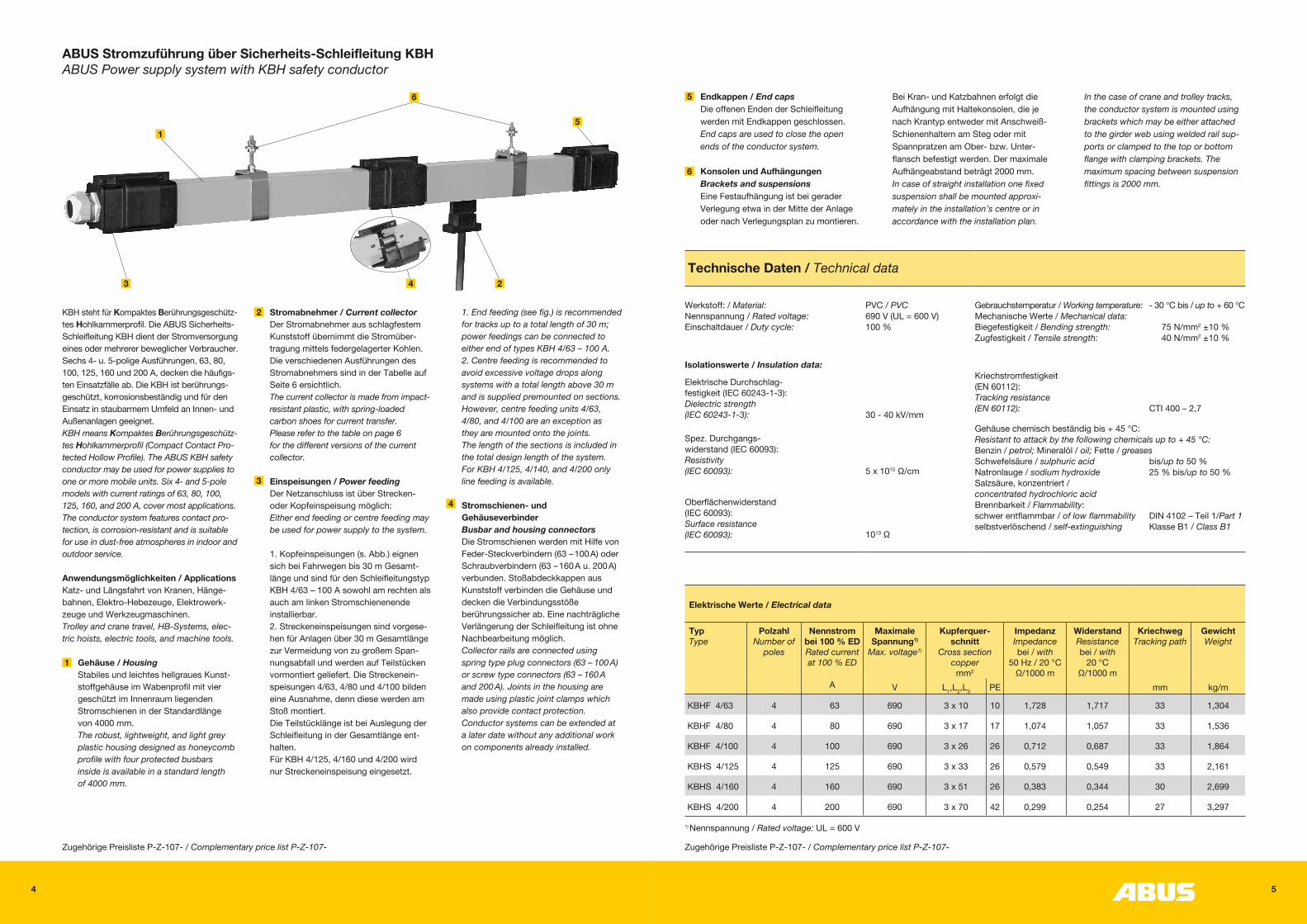
Endkappen / End capsDie offenen Enden der Schleifleitung werden mit Endkappen geschlossen.End caps are used to close the open ends of the conductor system.
Konsolen und AufhängungenBrackets and suspensionsEine Festaufhängung ist bei gerader Verlegung etwa in der Mitte der Anlage oder nach Verlegungsplan zu montieren.
ABUS Stromzuführung über Sicherheits-Schleifleitung KBHABUS Power supply system with KBH safety conductor
KBH steht für Kompaktes Berührungsgeschütz- tes Hohlkammerprofil. Die ABUS Sicherheits- Schleifleitung KBH dient der Stromversorgung eines oder mehrerer beweglicher Verbraucher. Sechs 4- u. 5-polige Ausführungen, 63, 80, 100, 125, 160 und 200 A, decken die häufigs- ten Einsatzfälle ab. Die KBH ist berührungs- geschützt, korrosionsbeständig und für den Einsatz in staubarmem Umfeld an Innen- und Außenanlagen geeignet.KBH means Kompaktes Berührungsgeschütz-tes Hohlkammerprofil (Compact Contact Pro-tected Hollow Profile). The ABUS KBH safety conductor may be used for power supplies to one or more mobile units. Six 4- and 5-pole models with current ratings of 63, 80, 100, 125, 160, and 200 A, cover most applications. The conductor system features contact pro- tection, is corrosion-resistant and is suitable for use in dust-free atmospheres in indoor and outdoor service.
Anwendungsmöglichkeiten / ApplicationsKatz- und Längsfahrt von Kranen, Hänge- bahnen, Elektro-Hebezeuge, Elektrowerk- zeuge und Werkzeugmaschinen.Trolley and crane travel, HB-Systems, elec- tric hoists, electric tools, and machine tools.
Gehäuse / Housing Stabiles und leichtes hellgraues Kunst- stoffgehäuse im Wabenprofil mit vier geschützt im Innenraum liegenden Stromschienen in der Standardlänge von 4000 mm. The robust, lightweight, and light grey plastic housing designed as honeycomb profile with four protected busbars inside is available in a standard length of 4000 mm.
Technische Daten / Technical data
Werkstoff: / Material: Nennspannung / Rated voltage: Einschaltdauer / Duty cycle:
PVC / PVC 690 V (UL = 600 V) 100 %
Gebrauchstemperatur / Working temperature: - 30 °C bis / up to + 60 °CMechanische Werte / Mechanical data:Biegefestigkeit / Bending strength: 75 N/mm2 ±10 %Zugfestigkeit / Tensile strength: 40 N/mm2 ±10 %
Isolationswerte / Insulation data:
Elektrische Durchschlag- festigkeit (IEC 60243-1-3): Dielectric strength (IEC 60243-1-3):
30 - 40 kV/mm
Kriechstromfestigkeit (EN 60112): Tracking resistance (EN 60112): CTI 400 – 2,7
Gehäuse chemisch beständig bis + 45 °C: Resistant to attack by the following chemicals up to + 45 °C: Benzin / petrol; Mineralöl / oil; Fette / greases Schwefelsäure / sulphuric acid bis/up to 50 % Natronlauge / sodium hydroxide 25 % bis/up to 50 % Salzsäure, konzentriert / concentrated hydrochloric acid Brennbarkeit / Flammability: schwer entflammbar / of low flammability DIN 4102 – Teil 1/Part 1 selbstverlöschend / self-extinguishing Klasse B1 / Class B1
Spez. Durchgangs- widerstand (IEC 60093): Resistivity (IEC 60093):
5 x 10¹⁵ Ω/cm
Oberflächenwiderstand (IEC 60093): Surface resistance (IEC 60093):
1013 Ω
Elektrische Werte / Electrical data
TypType
PolzahlNumber of
poles
Nennstrombei 100 % ED Rated currentat 100 % ED
Maximale Spannung1)
Max. voltage1)
Kupferquer-schnitt
Cross sectioncopper
mm2
Impedanz Impedancebei / with
50 Hz / 20 °CΩ/1000 m
Widerstand Resistancebei / with
20 °C Ω/1000 m
Kriechweg Tracking path
GewichtWeight
A V L1,L2,L3 PE mm kg/m
KBHF 4/63 4 63 690 3 x 10 10 1,728 1,717 33 1,304
KBHF 4/80 4 80 690 3 x 17 17 1,074 1,057 33 1,536
KBHF 4/100 4 100 690 3 x 26 26 0,712 0,687 33 1,864
KBHS 4/125 4 125 690 3 x 33 26 0,579 0,549 33 2,161
KBHS 4/160 4 160 690 3 x 51 26 0,383 0,344 30 2,699
KBHS 4/200 4 200 690 3 x 70 42 0,299 0,254 27 3,297
Zugehörige Preisliste P-Z-107- / Complementary price list P-Z-107- Zugehörige Preisliste P-Z-107- / Complementary price list P-Z-107-
1) Nennspannung / Rated voltage: UL = 600 V
Stromabnehmer / Current collector Der Stromabnehmer aus schlagfestem Kunststoff übernimmt die Stromüber- tragung mittels federgelagerter Kohlen. Die verschiedenen Ausführungen des Stromabnehmers sind in der Tabelle auf Seite 6 ersichtlich. The current collector is made from impact- resistant plastic, with spring-loaded carbon shoes for current transfer. Please refer to the table on page 6 for the different versions of the current collector.
Einspeisungen / Power feeding Der Netzanschluss ist über Strecken- oder Kopfeinspeisung möglich: Either end feeding or centre feeding may be used for power supply to the system.
1. Kopfeinspeisungen (s. Abb.) eignen sich bei Fahrwegen bis 30 m Gesamt- länge und sind für den Schleifleitungstyp KBH 4/63 – 100 A sowohl am rechten als auch am linken Stromschienenende installierbar. 2. Streckeneinspeisungen sind vorgese- hen für Anlagen über 30 m Gesamtlänge zur Vermeidung von zu großem Span- nungsabfall und werden auf Teilstücken vormontiert geliefert. Die Streckenein- speisungen 4/63, 4/80 und 4/100 bilden eine Ausnahme, denn diese werden am Stoß montiert. Die Teilstücklänge ist bei Auslegung der Schleifleitung in der Gesamtlänge ent- halten. Für KBH 4/125, 4/160 und 4/200 wird nur Streckeneinspeisung eingesetzt.
3
1
2 1. End feeding (see fig.) is recommended for tracks up to a total length of 30 m; power feedings can be connected to either end of types KBH 4/63 – 100 A. 2. Centre feeding is recommended to avoid excessive voltage drops along systems with a total length above 30 m and is supplied premounted on sections. However, centre feeding units 4/63, 4/80, and 4/100 are an exception as they are mounted onto the joints. The length of the sections is included in the total design length of the system. For KBH 4/125, 4/140, and 4/200 only line feeding is available.
Stromschienen- und Gehäuseverbinder Busbar and housing connectors Die Stromschienen werden mit Hilfe von Feder-Steckverbindern (63 – 100 A) oder Schraubverbindern (63 – 160 A u. 200 A) verbunden. Stoßabdeckkappen aus Kunststoff verbinden die Gehäuse und decken die Verbindungsstöße berührungssicher ab. Eine nachträgliche Verlängerung der Schleifleitung ist ohne Nachbearbeitung möglich. Collector rails are connected using spring type plug connectors (63 – 100 A) or screw type connectors (63 – 160 A and 200 A). Joints in the housing are made using plastic joint clamps which also provide contact protection. Conductor systems can be extended at a later date without any additional work on components already installed.
Bei Kran- und Katzbahnen erfolgt die Aufhängung mit Haltekonsolen, die je nach Krantyp entweder mit Anschweiß- Schienenhaltern am Steg oder mit Spannpratzen am Ober- bzw. Unter- flansch befestigt werden. Der maximale Aufhängeabstand beträgt 2000 mm.In case of straight installation one fixed suspension shall be mounted approxi- mately in the installation’s centre or in accordance with the installation plan.
In the case of crane and trolley tracks, the conductor system is mounted using brackets which may be either attached to the girder web using welded rail sup-ports or clamped to the top or bottom flange with clamping brackets. The maximum spacing between suspension fittings is 2000 mm.
1
3
6
5
4 2
4
6 7
85
177
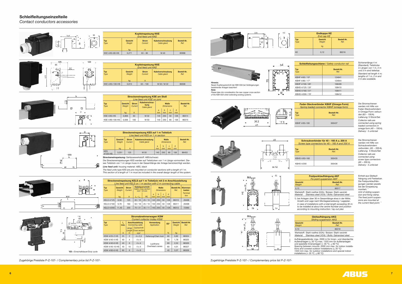
Streckeneinspeisung: Gehäusewerkstoff: ABS/schwarzDie Streckeneinspeisungen KES werden auf Teilstücken von 1 m Länge vormontiert. Die-ses Teilstück von 1 m Länge muss in der Gesamtlänge der Anlage berücksichtigt werden.Line feed unit: housing material: ABS, blackThe feed units type KES are pre-mounted on conductor sections with a length of 1 m. This section of a length of 1 m must be included in the overall design length of the system.
SchleifleitungseinzelteileContact conductors accessories
Kopfeinspeisung KKEEnd feed unit KKE
Typ Type
Gewicht Weight
Strom Current
Kabelverschraubung Cable gland
Bestell-Nr. Ref.
kg
A
KKE 4/63–80-HS 0,271 63 – 80 M 40 85998
Streckeneinspeisung KSE am StoßLine feed unit KSE on joint
Typ Type
Gewicht Weight
Strom Current
Kabelverschrau-bung
Cable glandMaße
DimensionsBestell-Nr.
Ref.
kg
A
a mm
b mm
c mm
d mm
KSE 4/63-HS 0,806 63 M 32 140 250 50 128 86314
KSE 4/80-100-HS 0,936 100 M 50 140 250 80 158 86315
Stromabnehmerwagen KSWCurrent collector trolley KSW
Typ Type
In max.
Anschlussleitung Connecting cable
Verwendung Application ED1) Gewicht
WeightBestell-Nr.
Ref. A
Länge Length
m
Querschnitt Cross section
mm2
%
kg
KSW 4/25-2 HS 25 2 4 x 2,5 Kettenzug/Chain hoist 60 0,82 86324KSW 4/40-4 HS 40 4 4 x 4
Laufkrane Overhead cranes
60 1,78 86325KSW 4/40-6 HS 40 6 4 x 4 60 2,52 86326KSW 4/40-10 HS 40 10 4 x 4 60 4,01 86327
KSW 4/60-6 HS 60 6 4 x 6 40 3,37 86328
Streckeneinspeisung KELS auf 1 m Teilstück mit 2 m AnschlussleitungLine feed unit KELS on 1 m section with 2 m connecting cable
Typ Type
Gewicht Weight
Strom Current
Kabelquerschnitt Cable cross section
mm2 / Ø mmMaße
DimensionsBestell-Nr.
Ref.Klemmen-
kastenTerminal
box kg
A
L1 – L3
PE
a mm
b mm
c mm
d mm
KELS 4/125 8,56 125 35 / 16 25 / 10 140 250 50 128 86310 26498
KELS 4/160 9,78 160 50 / 18 25 / 10 140 250 50 128 86311 26498
KELS 4/200 11,40 200 70 / 21 35 / 11 140 250 50 128 86312 72360
Streckeneinspeisung KES auf 1 m TeilstückLine feed unit KES on 1 m section
Typ Type
Gewicht Weight
Strom Current
Kabelverschraubung Cable gland
Maße Dimensions
Bestell-Nr. Ref.
kg
A
a mm
b mm
c mm
d mm
KES 4/125-HS 3,251 125 M 50 140 250 80 158 86453
Zugehörige Preisliste P-Z-107- / Complementary price list P-Z-107-
1)ED = Einschaltdauer/ Duty cycle
Kopfeinspeisung KKEEnd feed unit KKE
Typ Type
Gewicht Weight
Strom Current
Kabelverschraubung Cable gland
Bestell-Nr. Ref.
kg
A
KKE 4/63–100-HS 0,613 63 – 100 M 50 / M 32 86308
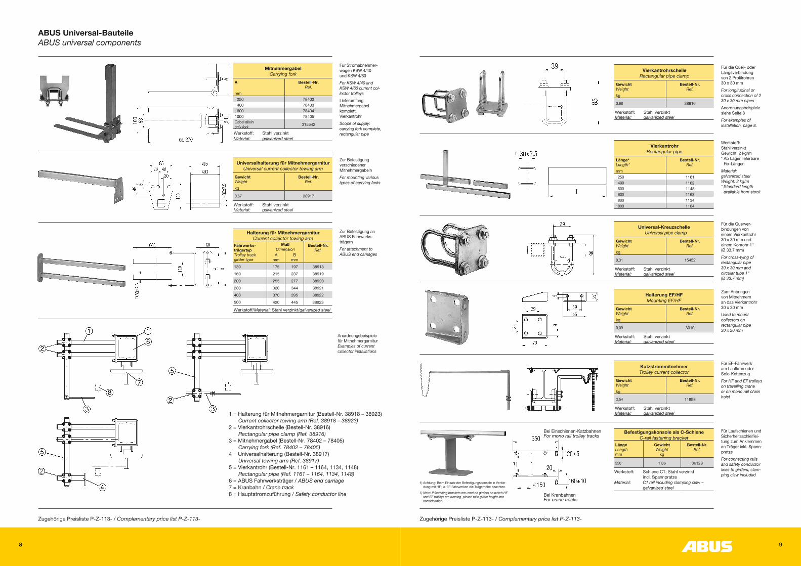
Schienenlänge 4 m (Standard); Teilstücke in Längen von 1 m, 2 m und 3 m sind lieferbar. Standard rail length 4 m; lengths of 1 m, 2 m and 3 m also available.
Einheit aus Gleitauf- hängung und Festsetzer. Die Festpunktaufhän- gungen werden jeweils bei der Einspeisung montiert. 1)
Unit of sliding suspen- sion and fixing clamp.The fixed point suspen- sions are mounted at the current feed point. 1)
Aufhängeabstände: max. 2000 m für Innen- und überdachte Außenanlagen (< 35 ºC) max. 1333 mm für Außenanlagen und spezielle Innenanlagen (> 35 ºC, < 60 ºC)Spacing between mounts: 2000 mm max. for indoor installa-tions and covered outdoor installations (< 35 ºC)1333 mm max. for outdoor installations and special indoor installations (> 35 ºC, < 60 ºC)
Die Stromschienen werden mit Hilfe von Feder-Steckverbindern in Omega-Form verbun- den (63 – 100 A). Lieferung: 5 Stück/SetCollector rails are connected using spring loaded connectors in omega form (40 – 100 A). Delivery: 5 units/set
Die Stromschienen werden mit Hilfe von Schraubverbindern verbunden. (40 – 200 A). Lieferung: 5 Stück/SetCollector rails are connected using screw type connectors (40 – 200 A). Delivery: 5 units/set
Schraubverbinder für 40 – 160 A u. 200 A Screw type connectors for 40 – 160 A and 200 A
Typ Type
Bestell-Nr. Ref.
KBHS 4/63–160 300435
KBHS 4/200 300436
Feder-Steckverbinder KBHF (Omega-Form) Spring loaded connector KBHF (omega form)
Typ Type
Bestell-Nr. Ref.
KBHF 4/63–100 300437
Festpunktaufhängung AKFFix point suspension AKF
Gewicht Weight
Bestell-Nr. Ref.
0,13 86317
Werkstoff: Stahl rostfrei (V2A) / Bolzen: Stahl verzinktMaterial: Stainless steel (V2A) / Bolts: Galvanized steel
Gleitaufhängung AKGSliding suspension AKG
Gewicht Weight
Bestell-Nr. Ref.
0,10 86318
Werkstoff: Stahl rostfrei (V2A) / Bolzen: Stahl verzinktMaterial: Stainless steel (V2A) / Bolts: Galvanized steel
Schleifleitungsschiene / Safety conductor rail
Typ Type
Bestell-Nr. Ref.
KBHF 4/63 / 102 124641KBHF 4/80 / 172 124644KBHF 4/100 / 262 108409KBHS 4/125 / 332 108410KBHS 4/160 / 512 108411KBHS 4/200 / 702 108412
1) bei Anlagen über 30 m Gesamtlänge etwa in der Mitte; Anzahl und Lage nach Montageanweisung / Lageplan. in case of installations with a total length exceeding 30 m: to be installed at about the centre Number and position according to mounting instruction / lay-out plan
Endkappe KEEnd cap KE
Typ Type
Gewicht Weight
Bestell-Nr. Ref.
kg
KE 0,12 86316
Zugehörige Preisliste P-Z-107- / Complementary price list P-Z-107-
Hinweis:Neuen Kupferquerschnitt der KBH 63A bei Verlängerungen bestehender Anlagen beachten!Note:Please take into consideration the new copper cross-section of the KBH 63A when extending existing systems.
8 9
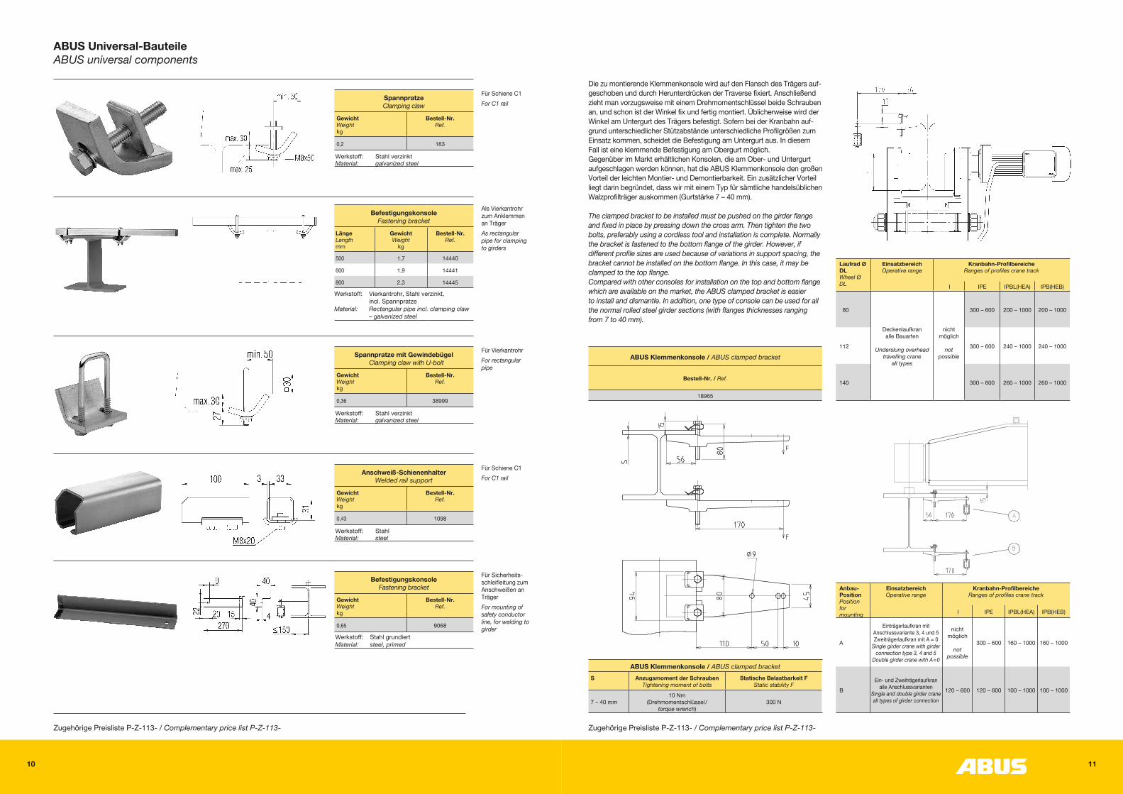
ABUS Universal-BauteileABUS universal components
Für Stromabnehmer-wagen KSW 4/40 und KSW 4/60For KSW 4/40 and KSW 4/60 current col-lector trolleysLieferumfang: Mitnehmergabel komplett, VierkantrohrScope of supply: carrying fork complete, rectangular pipe
Zur Befestigung verschiedener MitnehmergabelnFor mounting various types of carrying forks
Zur Befestigung an ABUS Fahrwerks-trägernFor attachment to ABUS end carriages
MitnehmergabelCarrying fork
A Bestell-Nr. Ref.
mm 250 78402 400 78403 600 784041000 78405Gabel allein only fork 315542
Werkstoff: Stahl verzinktMaterial: galvanized steel
Universalhalterung für MitnehmergarniturUniversal current collector towing arm
Gewicht Weight
Bestell-Nr. Ref.
kg
0,67 38917
Werkstoff: Stahl verzinktMaterial: galvanized steel
Halterung für MitnehmergarniturCurrent collector towing arm
Fahrwerks- trägertyp Trolley track girder type
Maß Dimension
Bestell-Nr. Ref.
A mm
B mm
130 175 197 38918160 215 237 38919200 255 277 38920280 320 344 38921400 370 395 38922500 420 445 38923
Werkstoff/Material: Stahl verzinkt/galvanized steel
Zugehörige Preisliste P-Z-113- / Complementary price list P-Z-113-
1 = Halterung für Mitnehmergarnitur (Bestell-Nr. 38918 – 38923) Current collector towing arm (Ref. 38918 – 38923)
2 = Vierkantrohrschelle (Bestell-Nr. 38916) Rectangular pipe clamp (Ref. 38916)
3 = Mitnehmergabel (Bestell-Nr. 78402 – 78405) Carrying fork (Ref. 78402 – 78405)
4 = Universalhalterung (Bestell-Nr. 38917) Universal towing arm (Ref. 38917)
5 = Vierkantrohr (Bestell-Nr. 1161 – 1164, 1134, 1148) Rectangular pipe (Ref. 1161 – 1164, 1134, 1148)
6 = ABUS Fahrwerksträger / ABUS end carriage7 = Kranbahn / Crane track8 = Hauptstromzuführung / Safety conductor line
Anordnungsbeispiele für Mitnehmergarnitur Examples of current collector installations
Werkstoff: Stahl verzinkt Gewicht: 2 kg/m * Ab Lager lieferbare
Fix-LängenMaterial: galvanized steel Weight: 2 kg/m * Standard length
available from stock
Für die Quer- oder Längsverbindung von 2 Profilrohren 30 x 30 mmFor longitudinal or cross connection of 2 30 x 30 mm pipesAnordnungsbeispiele siehe Seite 8For examples of installation, page 8.
Für die Querver- bindungen von einem Vierkantrohr 30 x 30 mm und einem Konrohr 1“ (Ø 33,7 mm)For cross-tying of rectangular pipe 30 x 30 mm and circular tube 1“ (Ø 33.7 mm)
Für Laufschienen und Sicherheitsschleiflei-tung zum Anklemmen an Träger inkl. Spann-pratzeFor connecting rails and safety conductor lines to girders, clam-ping claw included
1) Achtung: Beim Einsatz der Befestigungskonsole in Verbin-dung mit HF- u. EF-Fahrwerken die Trägerhöhe beachten.
1) Note: If fastening brackets are used on girders on which HF and EF trolleys are running, please take girder height into consideration.
Bei Einschienen-KatzbahnenFor mono rail trolley tracks
Bei KranbahnenFor crane tracks
Zum Anbringen von Mitnehmern an das Vierkantrohr 30 x 30 mmUsed to mount collectors on rectangular pipe 30 x 30 mm
Für EF-Fahrwerk am Laufkran oder Solo-KettenzugFor HF and EF trolleys on travelling crane or on mono rail chain hoist
VierkantrohrschelleRectangular pipe clamp
Gewicht Weight
Bestell-Nr. Ref.
kg
0,68 38916
Werkstoff: Stahl verzinktMaterial: galvanized steel
Universal-KreuzschelleUniversal pipe clamp
Gewicht Weight
Bestell-Nr. Ref.
kg
0,31 15452
Werkstoff: Stahl verzinktMaterial: galvanized steel
Halterung EF/HFMounting EF/HF
Gewicht Weight
Bestell-Nr. Ref.
kg
0,09 3010
Werkstoff: Stahl verzinktMaterial: galvanized steel
Katzstrommitnehmer Trolley current collector
Gewicht Weight
Bestell-Nr. Ref.
kg
3,54 11898
Werkstoff: Stahl verzinktMaterial: galvanized steel
VierkantrohrRectangular pipe
Länge* Length*
Bestell-Nr. Ref.
mm 250 1161 400 1162 500 1148 600 1163 800 11341000 1164
Befestigungskonsole als C-SchieneC-rail fastening bracket
Länge Length mm
Gewicht Weight
kg
Bestell-Nr. Ref.
550 1,06 36128
Werkstoff: Schiene C1; Stahl verzinkt incl. SpannpratzeMaterial: C1 rail including clamping claw – galvanized steel
Zugehörige Preisliste P-Z-113- / Complementary price list P-Z-113-
10 11
Für Sicherheits- schleifleitung zum Anschweißen an TrägerFor mounting of safety conductor line, for welding to girder
BefestigungskonsoleFastening bracket
Gewicht Weight kg
Bestell-Nr. Ref.
0,65 9068
Werkstoff: Stahl grundiertMaterial: steel, primed
Zugehörige Preisliste P-Z-113- / Complementary price list P-Z-113-
Für Schiene C1For C1 rail
Anschweiß-Schienenhalter Welded rail support
Gewicht Weight kg
Bestell-Nr. Ref.
0,43 1098
Werkstoff: StahlMaterial: steel
Für VierkantrohrFor rectangular pipe
Spannpratze mit GewindebügelClamping claw with U-bolt
Gewicht Weight kg
Bestell-Nr. Ref.
0,36 38999
Werkstoff: Stahl verzinktMaterial: galvanized steel
Als Vierkantrohr zum Anklemmen an TrägerAs rectangular pipe for clamping to girders
BefestigungskonsoleFastening bracket
Länge Length mm
Gewicht Weight
kg
Bestell-Nr. Ref.
500 1,7 14440
600 1,9 14441
800 2,3 14445
Werkstoff: Vierkantrohr, Stahl verzinkt, incl. SpannpratzeMaterial: Rectangular pipe incl. clamping claw
– galvanized steel
Für Schiene C1For C1 rail
SpannpratzeClamping claw
Gewicht Weight kg
Bestell-Nr. Ref.
0,2 163
Werkstoff: Stahl verzinktMaterial: galvanized steel
ABUS Universal-BauteileABUS universal components
Die zu montierende Klemmenkonsole wird auf den Flansch des Trägers auf- geschoben und durch Herunterdrücken der Traverse fixiert. Anschließend zieht man vorzugsweise mit einem Drehmomentschlüssel beide Schrauben an, und schon ist der Winkel fix und fertig montiert. Üblicherweise wird der Winkel am Untergurt des Trägers befestigt. Sofern bei der Kranbahn auf- grund unterschiedlicher Stützabstände unterschiedliche Profilgrößen zum Einsatz kommen, scheidet die Befestigung am Untergurt aus. In diesem Fall ist eine klemmende Befestigung am Obergurt möglich.Gegenüber im Markt erhältlichen Konsolen, die am Ober- und Untergurt aufgeschlagen werden können, hat die ABUS Klemmenkonsole den großen Vorteil der leichten Montier- und Demontierbarkeit. Ein zusätzlicher Vorteil liegt darin begründet, dass wir mit einem Typ für sämtliche handelsüblichen Walzprofilträger auskommen (Gurtstärke 7 – 40 mm).
The clamped bracket to be installed must be pushed on the girder flange and fixed in place by pressing down the cross arm. Then tighten the two bolts, preferably using a cordless tool and installation is complete. Normally the bracket is fastened to the bottom flange of the girder. However, if different profile sizes are used because of variations in support spacing, the bracket cannot be installed on the bottom flange. In this case, it may be clamped to the top flange.Compared with other consoles for installation on the top and bottom flange which are available on the market, the ABUS clamped bracket is easier to install and dismantle. In addition, one type of console can be used for all the normal rolled steel girder sections (with flanges thicknesses ranging from 7 to 40 mm).
ABUS Klemmenkonsole / ABUS clamped bracket
Bestell-Nr. / Ref.
18965
Laufrad Ø DL Wheel Ø DL
Einsatzbereich Operative range
Kranbahn-Profilbereiche Ranges of profiles crane track
I IPE IPBL(HEA) IPB(HEB)
80
Deckenlaufkran alle Bauarten
Underslung overhead travelling crane
all types
nicht möglich
not
possible
300 – 600 200 – 1000 200 – 1000
112 300 – 600 240 – 1000 240 – 1000
140 300 – 600 260 – 1000 260 – 1000
ABUS Klemmenkonsole / ABUS clamped bracketS Anzugsmoment der Schrauben
Tightening moment of boltsStatische Belastbarkeit F
Static stability F
7 – 40 mm10 Nm
(Drehmomentschlüssel / torque wrench)
300 N
Anbau- Position Position for mounting
Einsatzbereich Operative range
Kranbahn-Profilbereiche Ranges of profiles crane track
I IPE IPBL(HEA) IPB(HEB)
A
Einträgerlaufkran mit Anschlussvariante 3, 4 und 5 Zweiträgerlaufkran mit A = 0
Single girder crane with girder connection type 3, 4 and 5
Double girder crane with A=0
nicht möglich
not
possible
300 – 600 160 – 1000 160 – 1000
B
Ein- und Zweiträgerlaufkran alle Anschlussvarianten
Single and double girder crane all types of girder connection
120 – 600 120 – 600 100 – 1000 100 – 1000
Zugehörige Preisliste P-Z-113- / Complementary price list P-Z-113-
12 13
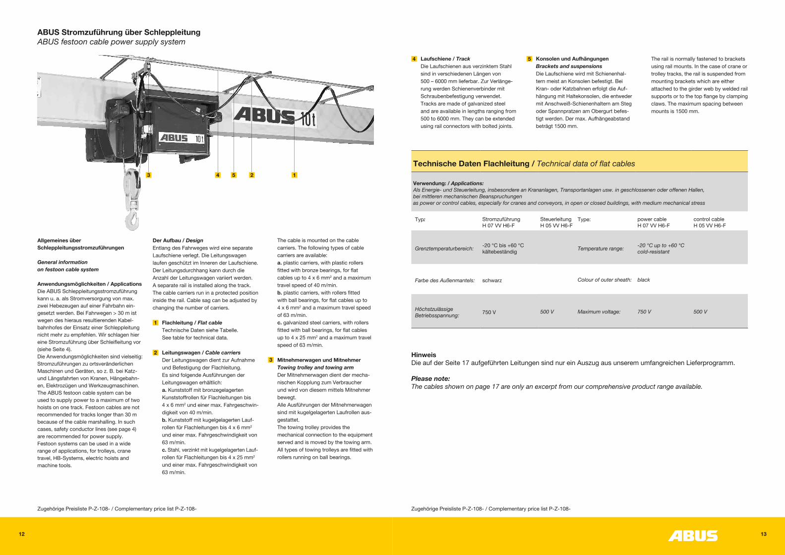
ABUS Stromzuführung über SchleppleitungABUS festoon cable power supply system
Allgemeines überSchleppleitungsstromzuführungen
General informationon festoon cable system
Anwendungsmöglichkeiten / ApplicationsDie ABUS Schleppleitungsstromzuführungkann u. a. als Stromversorgung von max.zwei Hebezeugen auf einer Fahrbahn ein- gesetzt werden. Bei Fahrwegen > 30 m istwegen des hieraus resultierenden Kabel- bahnhofes der Einsatz einer Schleppleitungnicht mehr zu empfehlen. Wir schlagen hiereine Stromzuführung über Schleifleitung vor(siehe Seite 4).Die Anwendungsmöglichkeiten sind vielseitig:Stromzuführungen zu ortsveränderlichenMaschinen und Geräten, so z. B. bei Katz- und Längsfahrten von Kranen, Hängebahn- en, Elektrozügen und Werkzeugmaschinen.The ABUS festoon cable system can be used to supply power to a maximum of two hoists on one track. Festoon cables are notrecommended for tracks longer than 30 mbecause of the cable marshalling. In suchcases, safety conductor lines (see page 4)are recommended for power supply.Festoon systems can be used in a widerange of applications, for trolleys, cranetravel, HB-Systems, electric hoists andmachine tools.
Der Aufbau / DesignEntlang des Fahrweges wird eine separateLaufschiene verlegt. Die Leitungswagenlaufen geschützt im Inneren der Laufschiene.Der Leitungsdurchhang kann durch dieAnzahl der Leitungswagen variiert werden.A separate rail is installed along the track.The cable carriers run in a protected positioninside the rail. Cable sag can be adjusted bychanging the number of carriers.
Flachleitung / Flat cable Technische Daten siehe Tabelle. See table for technical data.
Leitungswagen / Cable carriers Der Leitungswagen dient zur Aufnahme und Befestigung der Flachleitung. Es sind folgende Ausführungen der Leitungswagen erhältlich: a. Kunststoff mit bronzegelagerten Kunststoffrollen für Flachleitungen bis 4 x 6 mm2 und einer max. Fahrgeschwin- digkeit von 40 m/min. b. Kunststoff mit kugelgelagerten Lauf- rollen für Flachleitungen bis 4 x 6 mm2
und einer max. Fahrgeschwindigkeit von 63 m/min. c. Stahl, verzinkt mit kugelgelagerten Lauf- rollen für Flachleitungen bis 4 x 25 mm2 und einer max. Fahrgeschwindigkeit von 63 m/min.
The cable is mounted on the cable carriers. The following types of cable carriers are available: a. plastic carriers, with plastic rollers fitted with bronze bearings, for flat cables up to 4 x 6 mm2 and a maximum travel speed of 40 m/min. b. plastic carriers, with rollers fitted with ball bearings, for flat cables up to 4 x 6 mm2 and a maximum travel speed of 63 m/min. c. galvanized steel carriers, with rollers fitted with ball bearings, for flat cables up to 4 x 25 mm2 and a maximum travel speed of 63 m/min.
Mitnehmerwagen und Mitnehmer Towing trolley and towing arm Der Mitnehmerwagen dient der mecha- nischen Kopplung zum Verbraucher und wird von diesem mittels Mitnehmer bewegt. Alle Ausführungen der Mitnehmerwagen sind mit kugelgelagerten Laufrollen aus- gestattet. The towing trolley provides the mechanical connection to the equipment served and is moved by the towing arm. All types of towing trolleys are fitted with rollers running on ball bearings.
4 5Laufschiene / TrackDie Laufschienen aus verzinktem Stahlsind in verschiedenen Längen von500 – 6000 mm lieferbar. Zur Verlänge- rung werden Schienenverbinder mitSchraubenbefestigung verwendet.Tracks are made of galvanized steeland are available in lengths ranging from500 to 6000 mm. They can be extendedusing rail connectors with bolted joints.
Konsolen und AufhängungenBrackets and suspensions Die Laufschiene wird mit Schienenhal- tern meist an Konsolen befestigt. BeiKran- oder Katzbahnen erfolgt die Auf- hängung mit Haltekonsolen, die entwedermit Anschweiß-Schienenhaltern am Stegoder Spannpratzen am Obergurt befes- tigt werden. Der max. Aufhängeabstandbeträgt 1500 mm.
The rail is normally fastened to bracketsusing rail mounts. In the case of crane ortrolley tracks, the rail is suspended frommounting brackets which are eitherattached to the girder web by welded railsupports or to the top flange by clampingclaws. The maximum spacing betweenmounts is 1500 mm.
Technische Daten Flachleitung / Technical data of flat cables
Verwendung: / Applications:Als Energie- und Steuerleitung, insbesondere an Krananlagen, Transportanlagen usw. in geschlossenen oder offenen Hallen,bei mittleren mechanischen Beanspruchungenas power or control cables, especially for cranes and conveyors, in open or closed buildings, with medium mechanical stress
Typ: Stromzuführung H 07 VV H6-F
Steuerleitung H 05 VV H6-F
Type: power cable H 07 VV H6-F
control cable H 05 VV H6-F
Grenztemperaturbereich: -20 °C bis +60 °C kältebeständig Temperature range: -20 °C up to +60 °C
cold-resistant
Farbe des Außenmantels: schwarz Colour of outer sheath: black
Höchstzulässige Betriebsspannung: 750 V 500 V Maximum voltage: 750 V 500 V
Zugehörige Preisliste P-Z-108- / Complementary price list P-Z-108-Zugehörige Preisliste P-Z-108- / Complementary price list P-Z-108-
HinweisDie auf der Seite 17 aufgeführten Leitungen sind nur ein Auszug aus unserem umfangreichen Lieferprogramm.
Please note:The cables shown on page 17 are only an excerpt from our comprehensive product range available.
3 4 5 2 1
1
23
14 15
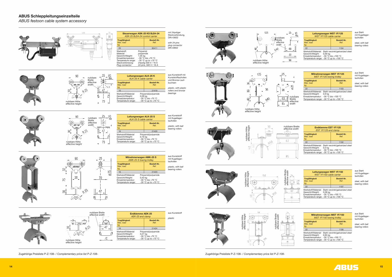
ABUS SchleppleitungseinzelteileABUS festoon cable system accessory
aus Kunststoff
plastic
nutzbare Breiteeffective width
nutzbare Höheeffective height
Endklemme AEK-25AEK-25 end clamp
Tragfähigkeit Max. load kg
Bestell-Nr. Ref.
16 21424Werkstoff/Material: Polyamid/polyamide Gewicht/Weight: 0,27 kgEinsatztemperatur: -30 °C bis +70 °CTemperature range: -30 °C up to +70 °C
mit 24poliger Steckverbindung, DIN 43652
with 24 pins plug connector DIN 43652
aus Kunststoff mit Kunststofflaufrollen und Bronze-Lauf-buchsen
plastic, with plastic rollers and bronze bearings
aus Kunststoff mit Kugellager-laufrollen
plastic, with ball bearing rollers
nutzbare Breiteeffective width
nutzbare Höheeffective height
nutzbare Breiteeffective width
nutzbare Höheeffective height
aus Kunststoff mit Kugellager-laufrollen
plastic, with ball bearing rollers
Steuerwagen ASK-25 KS BJ24-24ASK-25 BJ24-24 control carrier
Tragfähigkeit Max. load kg
Bestell-Nr. Ref.
20 85411Werkstoff: PolyamidMaterial: polyamideGewicht/Weight: 1,05 kgEinsatztemperatur: -30 °C bis +70 °CTemperature range: -30 °C up to +70 °CSteckverbindung: 24polig 500 V / 16 APlug connector: 24 pins, 500 V / 16 A
Leitungswagen ALK-25 KALK-25 K cable carrier
Tragfähigkeit Max. load kg
Bestell-Nr. Ref.
10 21419Werkstoff/Material: Polyamid/polyamide Gewicht/Weight: 0,09 kgEinsatztemperatur: -30 °C bis +70 °CTemperature range: -30 °C up to +70 °C
Leitungswagen ALK-25 SALK-25 S cable carrier
Tragfähigkeit Max. load kg
Bestell-Nr. Ref.
16 21420Werkstoff/Material: Polyamid/polyamide Gewicht/Weight: 0,16 kgEinsatztemperatur: -30 °C bis +70 °CTemperature range: -30 °C up to +70 °C
Mitnehmerwagen AMK-25 SAMK-25 S towing trolley
Tragfähigkeit Max. load kg
Bestell-Nr. Ref.
16 21423Werkstoff/Material: Polyamid/polyamide Gewicht/Weight: 0,43 kgEinsatztemperatur: -30 °C bis +70 °CTemperature range: -30 °C up to +70 °C
Zugehörige Preisliste P-Z-108- / Complementary price list P-Z-108-
aus Stahl mit Kugellager-laufrollen
steel, with ball bearing rollers
width
nutzbare Breiteeffective
nutzbare Höheeffective height
aus Stahl mit Kugellager-laufrollen
steel, with ball bearing rollers
nutzbare Breiteeffective width
nutzbare Höheeffective height
nutz
bare
Höh
eef
fect
ive h
eigh
t
Leitungswagen WST 1F/125WST 1F/125 cable carrier
Tragfähigkeit Max. load kg
Bestell-Nr. Ref.
22 1104Werkstoff/Material: Stahl verzinkt/galvanized steel Gewicht/Weight: 0,56 kgEinsatztemperatur: -30 °C bis +100 °CTemperature range: -30 °C up to +100 °C
Mitnehmerwagen MST 1F/125MST 1F/125 towing trolley
Tragfähigkeit Max. load kg
Bestell-Nr. Ref.
22 1103Werkstoff/Material: Stahl verzinkt/galvanized steel Gewicht/Weight: 0,9 kgEinsatztemperatur: -30 °C bis +100 °CTemperature range: -30 °C up to +100 °C
Endklemme EST 1F/125EST 1F/125 end clamp
Tragfähigkeit Max. load kg
Bestell-Nr. Ref.
22 1102Werkstoff/Material: Stahl verzinkt/galvanized steel Gewicht/Weight: 0,5 kgEinsatztemperatur: -30 °C bis +100 °CTemperature range: -30 °C up to +100 °C
Zugehörige Preisliste P-Z-108- / Complementary price list P-Z-108-
aus Stahl mit Kugellager-laufrollen
steel, with ball bearing rollers
nutz
bare
Höh
eef
fect
ive h
eigh
t Leitungswagen WST 1F/150WST 1F/150 cable carrier
Tragfähigkeit Max. load kg
Bestell-Nr. Ref.
22 1107Werkstoff/Material: Stahl verzinkt/galvanized steel Gewicht/Weight: 0,58 kgEinsatztemperatur: -30 °C bis +100 °CTemperature range: -30 °C up to +100 °C
aus Stahl mit Kugellager-laufrollen
steel, with ball bearing rollers
Mitnehmerwagen MST 1F/150MST 1F/150 towing trolley
Tragfähigkeit Max. load kg
Bestell-Nr. Ref.
22 1106Werkstoff/Material: Stahl verzinkt/galvanized steel Gewicht/Weight: 0,95 kgEinsatztemperatur: -30 °C bis +100 °CTemperature range: -30 °C up to +100 °C
nutz
bare
Bre
iteef
fect
ive w
idth
nutzbare Breiteeffective width
nutz
bare
Höh
eef
fect
ive h
eigh
t
nutz
bare
Bre
iteef
fect
ive w
idth
16 17
ABUS Elektro-InstallationsmaterialABUS electrical installation material
PVC-FlachleitungenAls Energie- und Steuerleitung für Leitungs-wagen (teilweise Energieketten), an Kran- anlagen. Geeignet für die Verwendung in trockenen, feuchten und nassen Räumen.Betriebstemperatur PVC: -20 °C bis +60 °CBetriebstemperatur PE: -20 °C bis +80 °C
PVC flat cablesTo be used as electrical power and control line for cable carriers (partly energy chain), on crane installations. Suited to use in dry, humid and damp rooms.Working temperature PVC: -20 °C up to +60 °CWorking temperature PE: -20 °C up to +80 °C
RundleitungenAls Energie- und Steuerleitung in elektrischen Anlagen. Geeignet für die Verwendung in trockenen, feuchten und nassen Räumen. Nicht im Freien ohne UV-Schutz verwenden. Betriebstemperatur fest: -30 °C bis +80 °C Betriebstemperatur bewegt: -5 °C bis +70 °C
Round cablesTo be used as electrical power and control line in electrical installations. Suited to use in dry, humid and damp rooms. Do not use outdoor without UV protection. Working temperature, non-movable cable: -30 °C up to +80 °C Working temperature, movable cable: -5 °C up to +70 °C
SteuerleitungenAls Energie- und Steuerleitung, besonders für Hängetaster an Hebezeugen. Mit zentralem Stahl-Tragorgan.Geeignet für die Verwendung in trockenen, feuchten und nassen Räumen, sowie im Freien.Betriebstemperatur bewegt: -30 °C bis +55 °C
Control cablesTo be used as electrical power and control line, especially for push button pendants on hoists. With inner steel supporting cable. Suited to use in dry, humid and damp rooms, as well as outdoor.Working temperature, movable cable: -30 °C up to +55 °C
Zugehörige Preisliste P-Z-109- / Complementary price list P-Z-109-
Mantel- Leitungstyp Anzahl Adern, Nennspannung U Aderkennung Außenmaß Verschraubung Bestell- Werkstoff Querschnitt in mm2 Adernummern Höhe x Breite metrisch Nr. Material of Type Number of conductors Rated voltage U Conductor marking Outside Cable gland Ref. cable sheathing of cable Cross section in mm2 Numbering height x width metric V of conductors mm PVC H05VVH6-F 4 X 1,0 500 sw, Ziffern 1 – 4 4,6 x 13,7 25 2136 PVC H05VVH6-F 5 G 1,0 500 gn/ge, bl, br, sw, gr 4,6 x 16,3 25 3703 PVC H05VVH6-F 8 G 1,0 500 gn/ge, sw Ziffern 1 – 7 4,6 x 24,8 40 766 PVC H05VVH6-F 8 X 1,0 500 sw, Ziffern 1 – 8 4,6 x 24,8 40 767 PE LIFY2YKFFL-JZ 12 G 1,0 500 gn/ge, sw Ziffern 1 – 11 2,6 x 25,5 40 304084 PE LIFY2YKFFL-OZ 12 X 1,0 500 sw Ziffern 1 – 12 2,6 x 25,5 40 304083 PVC H07VVH6-F 4 X 1,5 750 sw, Ziffern 1 – 4 5,2 x 15,1 25 760 PVC H07VVH6-F 4 G 1,5 750 gn/ge, br, sw, gr 5,2 x 15,1 25 759 PVC H07VVH6-F 8 X 1,5 750 sw, Ziffern 1 – 8 5,0 x 27,8 40 782 PVC H07VVH6-F 8 G 1,5 750 gn/ge, sw Ziffern 1 – 7 5,0 x 27,8 40 75121 PVC H07VVH6-F 4 G x 2,5 750 gn/ge, br, sw, gr 5,8 x 17,9 32 761 PVC H07VVH6-F 4 G x 4,0 750 gn/ge, br, sw, gr 6,7 x 19,8 32 762 PVC H07VVH6-F 4 G x 6,0 750 gn/ge, br, sw, gr 7,2 x 22,3 40 763 PVC A07VVH6-F 4 G x 10,0 750 gn/ge, br, sw, gr 8,8 x 29,0 40 303371 PVC A07VVH6-F 4 G x 16,0 750 gn/ge, br, sw, gr 10,0 x 33,6 50 303372 PVC A07VVH6-F 4 G x 25,0 750 gn/ge, br, sw, gr 12,0 x 40,3 63 303349 PVC A07VVH6-F 4 G x 35,0 750 gn/ge, br, sw, gr 13,6 x 45,5 63 303373
Mantel- Leitungstyp Anzahl Adern, Nennspannung U Aderkennung Leitungs- Verschraubung Bestell- Werkstoff Querschnitt in mm2 Adernummer durchmesser metrisch Nr. Material of Type Number of conductors Rated voltage U Conductor marking Cable Cable gland Ref. cable sheathing of cable Cross section in mm2 Numbering diameter metric V of conductors mm PVC ÖPVC-JZ 5 G 1,0 500 gn/ge, sw Ziffern 1 – 4 7,3 16 774 PVC ÖPVC-OZ 8 X 1,0 500 sw Ziffern 1 – 8 9,5 16/20 577 PVC ÖPVC-JZ 25 G 1,0 500 gn/ge, sw Ziffern 1 – 24 14,9 25 14432 PVC ÖPVC-JZ 4 G 1,5 500 gn/ge, sw Ziffern 1 – 3 7,4 16 4892 PVC ÖPVC-JZ 7 G 1,5 500 gn/ge, sw Ziffern 1 – 6 9,1 16/20 6753 PVC ÖPVC-JZ 12 G 1,5 500 gn/ge, sw Ziffern 1 – 11 11,7 20/25 6203 PVC ÖPVC-JZ 18 G 1,5 500 gn/ge, sw Ziffern 1 – 17 14,7 25 4112 PVC ÖPVC-JZ 4 G 2,5 500 gn/ge, sw Ziffern 1 – 3 9,1 16/20 771 PVC ÖPVC-JZ 7 G 2,5 500 gn/ge, sw Ziffern 1 – 6 11,3 20/25 10000 PVC ÖPVC-JZ 12 G 2,5 500 gn/ge, sw Ziffern 1 – 11 14,7 25 6902 PVC ÖPVC-JZ 4 G 4,0 500 gn/ge, sw Ziffern 1 – 3 11,0 20/25 3979 PVC ÖPVC-JZ 4 G 6,0 500 gn/ge, sw Ziffern 1 – 3 12,7 20/25 773 PVC ÖPVC-JZ 4 G 10,0 500 gn/ge, sw Ziffern 1 – 3 16,4 25/32 775 PVC ÖPVC-JZ 4 G 16,0 500 gn/ge, sw Ziffern 1 – 3 20,1 32/40 776 PVC ÖPVC-JZ 4 G 25,0 500 gn/ge, sw Ziffern 1 – 3 22,9 40 19503 PVC ÖPVC-JZ 4 G 35,0 500 gn/ge, sw Ziffern 1 – 3 28,9 50 19158 PVC ÖPVC-JZ 4 G 50,0 500 gn/ge, sw Ziffern 1 – 3 34,7 63 34315
Mantel- Leitungstyp Anzahl Adern, Nennspannung U Aderkennung Leitungs- Verschraubung Bestell- Werkstoff Querschnitt in mm2 Adernummer durchmesser metrisch Nr. Material of Type Number of conductors Rated voltage U Conductor marking Cable Cable gland Ref. cable sheathing of cable Cross section in mm2 Numbering diameter metric V of conductors mm PVC YMHYKST-OZ 6 x 1,0 500 sw, Ziffern 1 – 6 12,2 20/25 12172 PVC YMHYKST-OZ 18 x 1,0 500 sw, Ziffern 1 – 18 14,9 25,0 12173 PVC YMHYKST-OZ 24 x 1,0 500 sw, Ziffern 1 – 24 17,8 32,0 12174
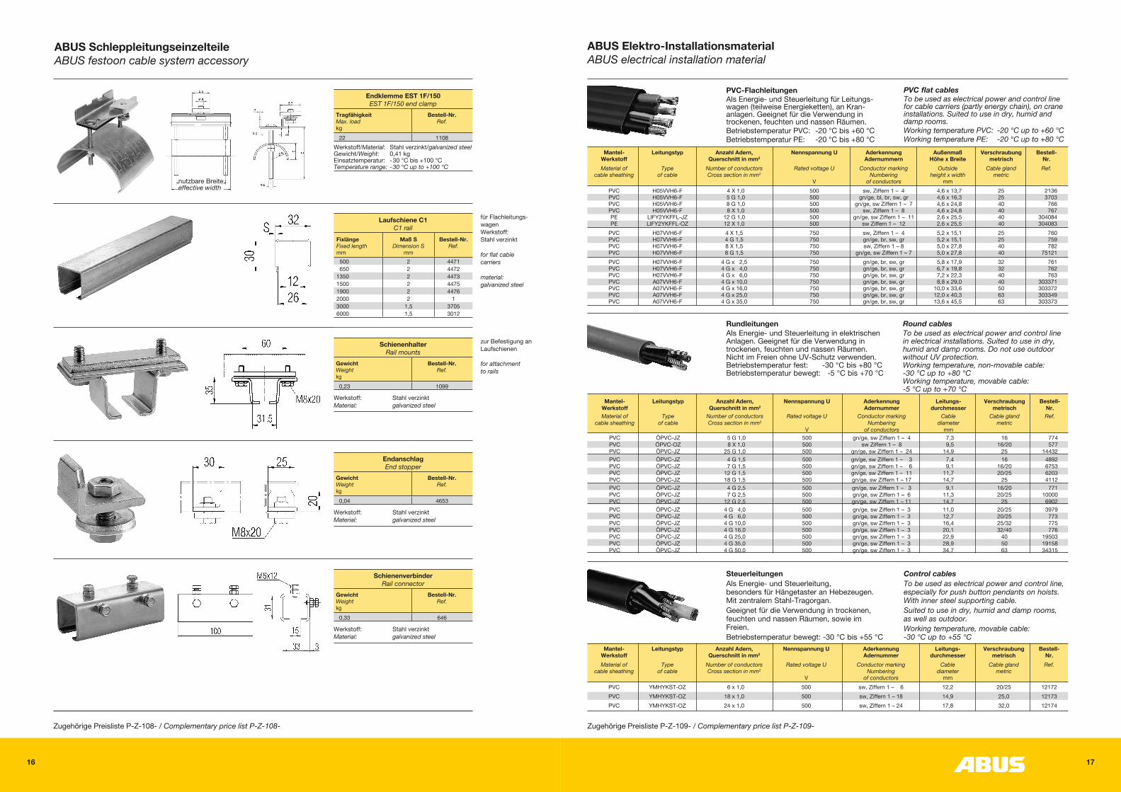
ABUS SchleppleitungseinzelteileABUS festoon cable system accessory
EndanschlagEnd stopper
Gewicht Weight kg
Bestell-Nr. Ref.
0,04 4653
Werkstoff: Stahl verzinktMaterial: galvanized steel
SchienenverbinderRail connector
Gewicht Weight kg
Bestell-Nr. Ref.
0,33 646
Werkstoff: Stahl verzinktMaterial: galvanized steel
Zugehörige Preisliste P-Z-108- / Complementary price list P-Z-108-
für Flachleitungs-wagen Werkstoff: Stahl verzinkt
for flat cable carriers
material: galvanized steel
Laufschiene C1C1 rail
Fixlänge Fixed length mm
Maß S Dimension S
mm
Bestell-Nr. Ref.
500 2 4471 650 2 44721350 2 44731500 2 44751900 2 44762000 2 13000 1,5 37056000 1,5 3012
zur Befestigung an Laufschienen
for attachment to rails
SchienenhalterRail mounts
Gewicht Weight kg
Bestell-Nr. Ref.
0,23 1099
Werkstoff: Stahl verzinktMaterial: galvanized steel
nutzbare Breiteeffective width
Endklemme EST 1F/150EST 1F/150 end clamp
Tragfähigkeit Max. load kg
Bestell-Nr. Ref.
22 1108Werkstoff/Material: Stahl verzinkt/galvanized steel Gewicht/Weight: 0,41 kgEinsatztemperatur: -30 °C bis +100 °CTemperature range: -30 °C up to +100 °C
18 19
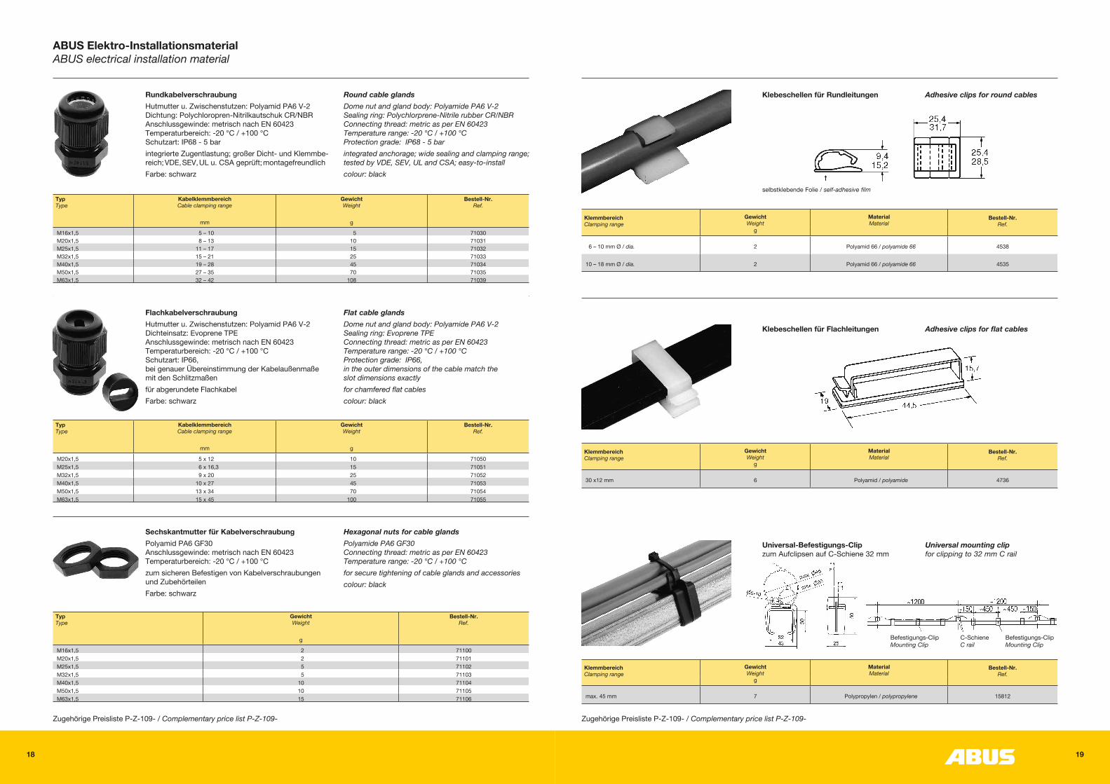
RundkabelverschraubungHutmutter u. Zwischenstutzen: Polyamid PA6 V-2 Dichtung: Polychloropren-Nitrilkautschuk CR/NBR Anschlussgewinde: metrisch nach EN 60423 Temperaturbereich: -20 °C / +100 °C Schutzart: IP68 - 5 barintegrierte Zugentlastung; großer Dicht- und Klemmbe- reich; VDE, SEV, UL u. CSA geprüft; montagefreundlichFarbe: schwarz
Round cable glandsDome nut and gland body: Polyamide PA6 V-2 Sealing ring: Polychlorprene-Nitrile rubber CR/NBR Connecting thread: metric as per EN 60423 Temperature range: -20 °C / +100 °C Protection grade: IP68 - 5 barintegrated anchorage; wide sealing and clamping range; tested by VDE, SEV, UL and CSA; easy-to-installcolour: black
Typ Type
Kabelklemmbereich Cable clamping range
mm
Gewicht Weight
g
Bestell-Nr. Ref.
M16x1,5 5 – 10 5 71030M20x1,5 8 – 13 10 71031M25x1,5 11 – 17 15 71032M32x1,5 15 – 21 25 71033M40x1,5 19 – 28 45 71034M50x1,5 27 – 35 70 71035M63x1,5 32 – 42 108 71039
Typ Type
Kabelklemmbereich Cable clamping range
mm
Gewicht Weight
g
Bestell-Nr. Ref.
M20x1,5 5 x 12 10 71050M25x1,5 6 x 16,3 15 71051M32x1,5 9 x 20 25 71052M40x1,5 10 x 27 45 71053M50x1,5 13 x 34 70 71054M63x1,5 15 x 45 100 71055
Typ Type
Gewicht Weight
g
Bestell-Nr. Ref.
M16x1,5 2 71100M20x1,5 2 71101M25x1,5 5 71102M32x1,5 5 71103M40x1,5 10 71104M50x1,5 10 71105M63x1,5 15 71106
FlachkabelverschraubungHutmutter u. Zwischenstutzen: Polyamid PA6 V-2 Dichteinsatz: Evoprene TPE Anschlussgewinde: metrisch nach EN 60423 Temperaturbereich: -20 °C / +100 °C Schutzart: IP66, bei genauer Übereinstimmung der Kabelaußenmaße mit den Schlitzmaßenfür abgerundete FlachkabelFarbe: schwarz
Flat cable glandsDome nut and gland body: Polyamide PA6 V-2 Sealing ring: Evoprene TPE Connecting thread: metric as per EN 60423 Temperature range: -20 °C / +100 °C Protection grade: IP66, in the outer dimensions of the cable match the slot dimensions exactlyfor chamfered flat cablescolour: black
Sechskantmutter für KabelverschraubungPolyamid PA6 GF30 Anschlussgewinde: metrisch nach EN 60423 Temperaturbereich: -20 °C / +100 °Czum sicheren Befestigen von Kabelverschraubungen und ZubehörteilenFarbe: schwarz
Hexagonal nuts for cable glandsPolyamide PA6 GF30 Connecting thread: metric as per EN 60423 Temperature range: -20 °C / +100 °Cfor secure tightening of cable glands and accessoriescolour: black
ABUS Elektro-InstallationsmaterialABUS electrical installation material
Zugehörige Preisliste P-Z-109- / Complementary price list P-Z-109-
Klebeschellen für Rundleitungen Adhesive clips for round cables
selbstklebende Folie / self-adhesive film
Klemmbereich Clamping range
Gewicht Weight
Material Material
Bestell-Nr. Ref.
g
6 – 10 mm Ø / dia. 2 Polyamid 66 / polyamide 66 4538
10 – 18 mm Ø / dia. 2 Polyamid 66 / polyamide 66 4535
Klebeschellen für Flachleitungen Adhesive clips for flat cables
Klemmbereich Clamping range
Gewicht Weight
Material Material
Bestell-Nr. Ref.
g
30 x12 mm 6 Polyamid / polyamide 4736
Befestigungs-Clip C-Schiene Befestigungs-Clip Mounting Clip C rail Mounting Clip
Universal-Befestigungs-Clip zum Aufclipsen auf C-Schiene 32 mm
Universal mounting clip for clipping to 32 mm C rail
Zugehörige Preisliste P-Z-109- / Complementary price list P-Z-109-
Klemmbereich Clamping range
Gewicht Weight
Material Material
Bestell-Nr. Ref.
g
max. 45 mm 7 Polypropylen / polypropylene 15812
20 21
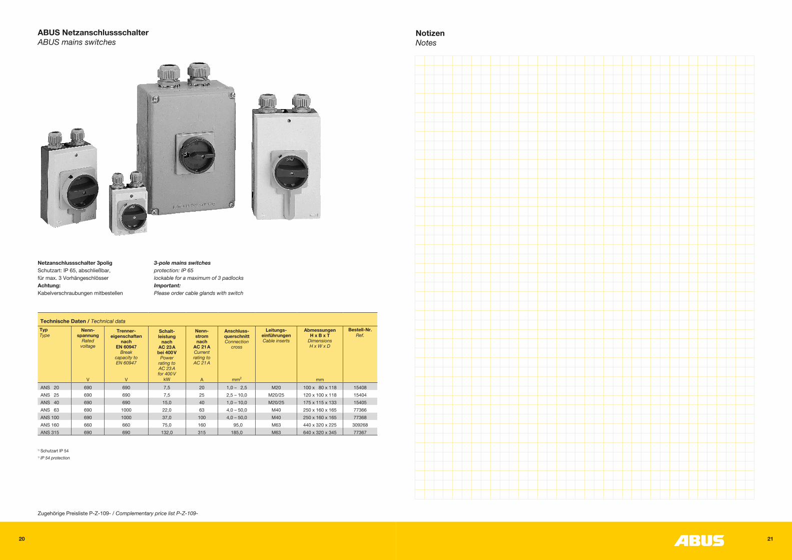
ABUS NetzanschlussschalterABUS mains switches
Netzanschlussschalter 3poligSchutzart: IP 65, abschließbar, für max. 3 VorhängeschlösserAchtung:Kabelverschraubungen mitbestellen
3-pole mains switchesprotection: IP 65lockable for a maximum of 3 padlocksImportant:Please order cable glands with switch
1) Schutzart IP 541) IP 54 protection
Technische Daten / Technical dataTyp Type
Nenn- spannung
Rated voltage
V
Trenner- eigenschaften
nach EN 60947
Break capacity to EN 60947
V
Schalt- leistung
nach AC 23 A bei 400 V
Power rating to AC 23 A for 400 V
kW
Nenn- strom nach
AC 21 A Current rating to AC 21 A
A
Anschluss- querschnitt Connection
cross
mm2
Leitungs- einführungen Cable inserts
Abmessungen H x B x T
Dimensions H x W x D
mm
Bestell-Nr. Ref.
ANS 20 690 690 7,5 20 1,0 – 2,5 M20 100 x 80 x 118 15408ANS 25 690 690 7,5 25 2,5 – 10,0 M20/25 120 x 100 x 118 15404ANS 40 690 690 15,0 40 1,0 – 10,0 M20/25 175 x 115 x 133 15405ANS 63 690 1000 22,0 63 4,0 – 50,0 M40 250 x 160 x 165 77366ANS 100 690 1000 37,0 100 4,0 – 50,0 M40 250 x 160 x 165 77368ANS 160 660 660 75,0 160 95,0 M63 440 x 320 x 225 309268ANS 315 690 690 132,0 315 185,0 M63 640 x 320 x 345 77367
Zugehörige Preisliste P-Z-109- / Complementary price list P-Z-109-
NotizenNotes
22 23
NotizenNotes

AN 3
0150
6 7.
19
ABUS Kransysteme GmbH · Postfach 100162 · 51601 Gummersbach Telefon 02261 37-0 · Telefax 02261 37-247E-Mail: [email protected] · www.abus-kransysteme.de
Recommended