Embed Size (px)
Citation preview
erstellt am: 03.05.04 E4-WM4-Y544A00_1 Seite 1 von 20 geändert am: 14.03.05
Inhalt:
- Teile- Gutachten für: ( herausnehmbar)
- Smart Fortwo Coupe ab 03.01
- Smart Fortwo Cabrio ab 03.01
- Smart Roadster
- Smart Coupe
- Einbauanleitungen
- englischer Anhang
Contents:
- certificate ( removable) for:
Smart Fortwo Coupe ab 03.01 -
Smart Fortwo Cabrio ab 03.01 -
Smart Roadster -
Smart Coupe -
- mounting instruction
- english enclosure
erstellt am: 03.05.04 E4-WM4-Y544A00_1 Seite 2 von 20 geändert am: 14.03.05
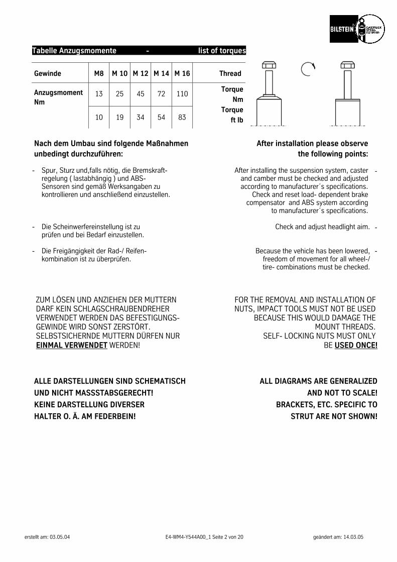
Tabelle Anzugsmomente - list of torques
Gewinde M8 M 10 M 12 M 14 M 16 Thread
Anzugsmoment Nm
13 25 45 72 110
10 19 34 54 83
Torque
Nm
Torque
ft lb
Nach dem Umbau sind folgende Maßnahmen unbedingt durchzuführen:
After installation please observe the following points:
- Spur, Sturz und,falls nötig, die Bremskraft-
regelung ( lastabhängig ) und ABS- Sensoren sind gemäß Werksangaben zu kontrollieren und anschließend einzustellen.
After installing the suspension system, caster and camber must be checked and adjusted according to manufacturer´s specifications.
Check and reset load- dependent brake compensator and ABS system according
to manufacturer´s specifications.
-
- Die Scheinwerfereinstellung ist zu
prüfen und bei Bedarf einzustellen. Check and adjust headlight aim. -
- Die Freigängigkeit der Rad-/ Reifen-
kombination ist zu überprüfen. Because the vehicle has been lowered,
freedom of movement for all wheel-/ tire- combinations must be checked.
-
ZUM LÖSEN UND ANZIEHEN DER MUTTERN DARF KEIN SCHLAGSCHRAUBENDREHER VERWENDET WERDEN DAS BEFESTIGUNGS- GEWINDE WIRD SONST ZERSTÖRT. SELBSTSICHERNDE MUTTERN DÜRFEN NUR EINMAL VERWENDET WERDEN!
FOR THE REMOVAL AND INSTALLATION OF NUTS, IMPACT TOOLS MUST NOT BE USED
BECAUSE THIS WOULD DAMAGE THE MOUNT THREADS.
SELF- LOCKING NUTS MUST ONLY BE USED ONCE!
ALLE DARSTELLUNGEN SIND SCHEMATISCH
UND NICHT MASSSTABSGERECHT!
KEINE DARSTELLUNG DIVERSER
HALTER O. Ä. AM FEDERBEIN!
ALL DIAGRAMS ARE GENERALIZED
AND NOT TO SCALE!
BRACKETS, ETC. SPECIFIC TO
STRUT ARE NOT SHOWN!
erstellt am: 03.05.04 E4-WM4-Y544A00_1 Seite 3 von 20 geändert am: 14.03.05
Einbauanleitung für Vorderachse - mounting instruction for front axle VN8-A764
Ausbau Das Fahrzeug auf eine radfreie Hebebühne stellen, anheben und Räder demontieren. Bei Fahrzeugen mit Xenon- Licht ist vor dem Ausbau der Federbeine, der Sensor für die Leuchtweitenregulierung auszubauen.
Die Schräglenker sind beim Ausbau stets mit geeignetem Hilfswerkzeug abzustützen!
Die untere Befestigung lösen und entfernen. Die obere Befestigungsmutter am Stützlager entfernen. Nicht die Kolbenstangen- Mutter lösen! Das Federbein komplett ausbauen und in einem geeigneten Spannbock spannen. Die Feder mit einem Spanngerät so weit vorspannen, bis das Stützlager frei ist. Mutter, Original- Anbauteile und Original- Feder demontieren. Hierbei ist zu prüfen, welche Original- Anbauteile durch Bilstein- Anbauteile ( Lieferumfang ) ersetzt werden.
Einbau BILSTEIN und/ oder Original- Anbauteile, sowie die neue BILSTEIN- Feder in umgekehrter Reihenfolge, ana-log zum Ausbau, auf BILSTEIN- Federbein montieren.
Der im Gutachten angegebene Verstell- bereich der Federteller darf nicht unter- oder überschritten werden!
Die Einbaulage der Federn ist an der Bedruckung ablesbar. Die Federbezeichnung muß in Einbaulage lesbar sein. Das komplettierte BILSTEIN- Federbein in umgekehrter Reihenfolge analog zum Ausbau wieder montieren. Federbeine/ Dämpfer die in Gummiaufhängungen gelagert sind, dürfen erst angezogen werden, wenn das Fahrzeug wieder auf dem Boden steht. Andere Befestigungen (z. B. Schellen) müssen vor dem Herablassen des Fahrzeugs angezogen werden. Achten Sie dabei auf eine korrekte Befestigung der Gummipuffer sowie des Schutzrohres.
Removal
Place vehicle on a chassis hoist, lift it and remove wheels.
Vehicles equipped with xenon
headlight the sensor for the headlamp levelling controller must removed bevor.
The lower control arm must be supported by suitable means!
Remove bottom mount.
Remove top fixing nut from support bearing. Do not remove center nut at this time!
Remove complete strut and
clamp it in an appropriate strut vise.
Using a suitable spring compressor,compress suspen-sion spring until tension on support bearing is released.
Release center nut and remove original
mounting parts and coil spring. Please refer to diagram to identify which parts will be re-
placed with BILSTEIN- supplied components.
Install
Assemble BILSTEIN and/ or original mounting parts, as well as the new BILSTEIN spring on the
BILSTEIN strut in reverse sequence of removal.
IMPORTANT! Spring plates must not be adjusted outside the
ranges specified below!
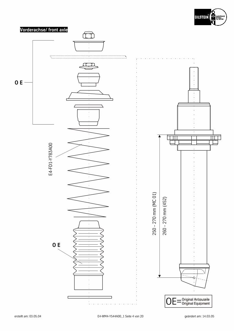
The correct mounting position of the suspension springs can be determined by the printing on
the springs; install them with the print upright.
Fit assembled BILSTEIN strut to the vehicle in reverse sequence to removal.
All rubber- mounted strut/ damper attachments must not
be fully tightened until AFTER the suspension system is loaded (wheels on the ground). Other
mounting fasteners (for example brackets) must be securely tightened BEFORE load is placed on the
suspension system. Make sure that the bump stop and dust cover are correctly and properly fastened.
erstellt am: 03.05.04 E4-WM4-Y544A00_1 Seite 4 von 20 geändert am: 14.03.05
Vorderachse/ front axle
O E
O E
E4-F
D1-
Y783
A00
250
- 27
0 m
m (M
C 0
1)
260
- 27
0 m
m (4
52)
OE=
erstellt am: 03.05.04 E4-WM4-Y544A00_1 Seite 5 von 20 geändert am: 14.03.05
erstellt am: 03.05.04 E4-WM4-Y544A00_1 Seite 6 von 20 geändert am: 14.03.05
erstellt am: 03.05.04 E4-WM4-Y544A00_1 Seite 7 von 20 geändert am: 14.03.05
erstellt am: 03.05.04 E4-WM4-Y544A00_1 Seite 8 von 20 geändert am: 14.03.05
erstellt am: 03.05.04 E4-WM4-Y544A00_1 Seite 9 von 20 geändert am: 14.03.05
erstellt am: 03.05.04 E4-WM4-Y544A00_1 Seite 10 von 20 geändert am: 14.03.05
erstellt am: 03.05.04 E4-WM4-Y544A00_1 Seite 11 von 20 geändert am: 14.03.05
erstellt am: 03.05.04 E4-WM4-Y544A00_1 Seite 12 von 20 geändert am: 14.03.05
erstellt am: 03.05.04 E4-WM4-Y544A00_1 Seite 13 von 20 geändert am: 14.03.05
erstellt am: 03.05.04 E4-WM4-Y544A00_1 Seite 14 von 20 geändert am: 14.03.05
erstellt am: 03.05.04 E4-WM4-Y544A00_1 Seite 15 von 20 geändert am: 14.03.05
erstellt am: 03.05.04 E4-WM4-Y544A00_1 Seite 16 von 20 geändert am: 14.03.05
ThyssenKrupp Bilstein Suspension GmbH August-Bilstein-Str. 4, 58256 Ennepetal
Postfach 11 51, 58240 Ennepetal Telefon: (0 23 33) 791-0, Telefax: (0 23 33) 7 91- 4900
Hotline: 01805- 600- 860; Internet: www.bilstein.de
erstellt am: 03.05.04 E4-WM4-Y544A00_1 Seite 17 von 20 geändert am: 14.03.05
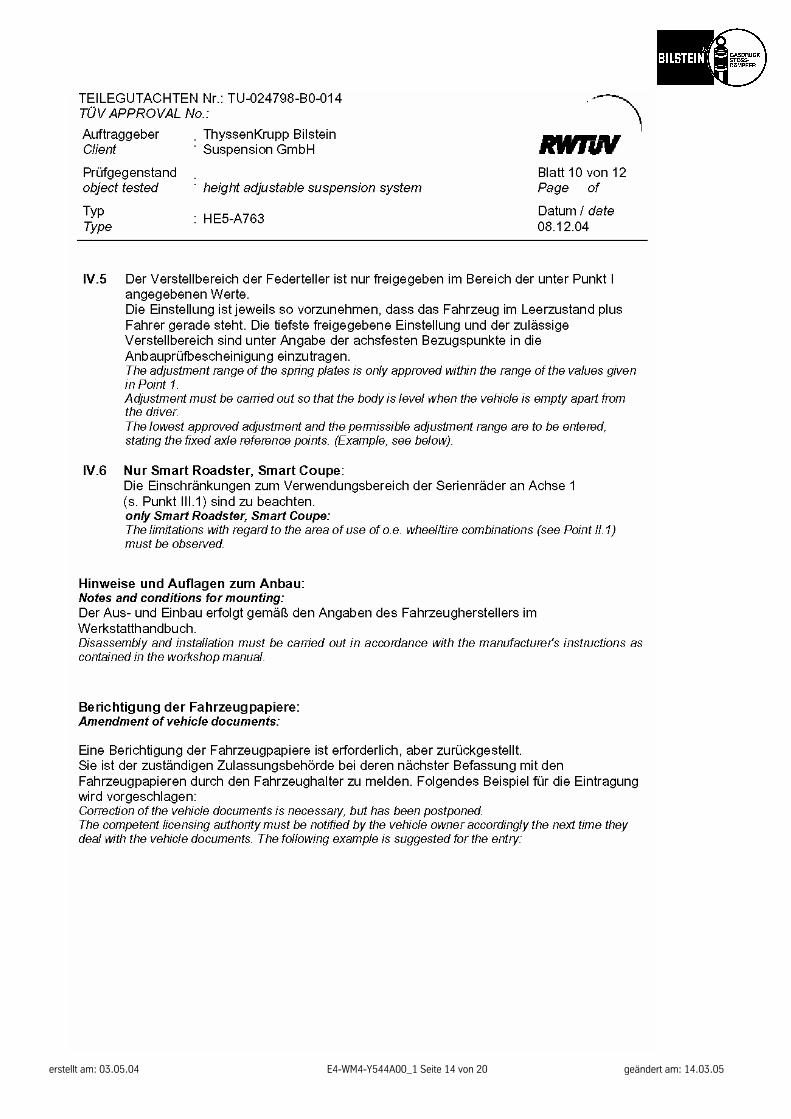
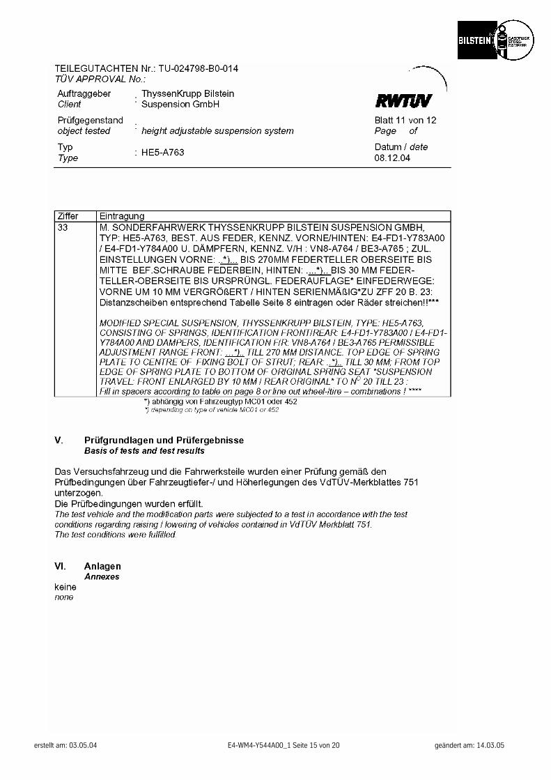
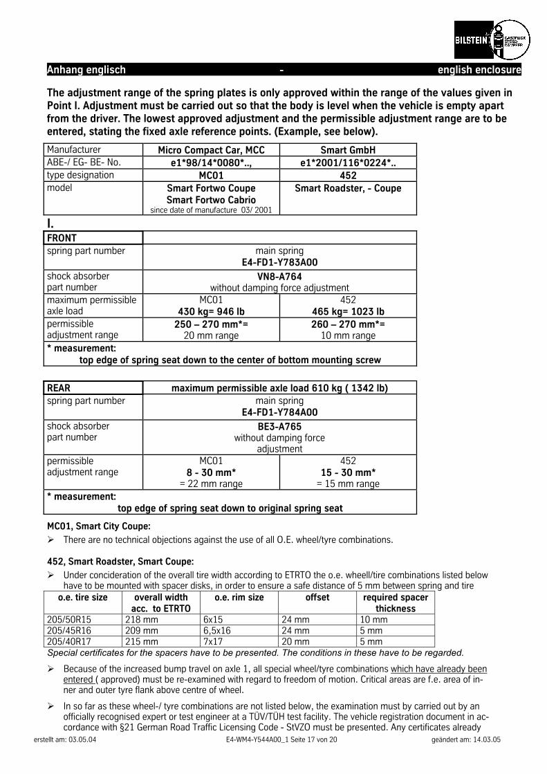
Anhang englisch - english enclosure The adjustment range of the spring plates is only approved within the range of the values given in Point I. Adjustment must be carried out so that the body is level when the vehicle is empty apart from the driver. The lowest approved adjustment and the permissible adjustment range are to be entered, stating the fixed axle reference points. (Example, see below).
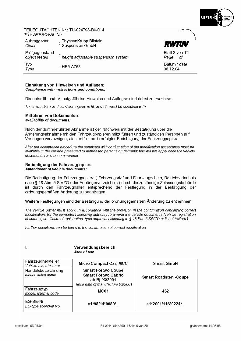
Manufacturer Micro Compact Car, MCC Smart GmbH ABE-/ EG- BE- No. e1*98/14*0080*.., e1*2001/116*0224*.. type designation MC01 452 model Smart Fortwo Coupe
Smart Fortwo Cabrio since date of manufacture 03/ 2001
Smart Roadster, - Coupe
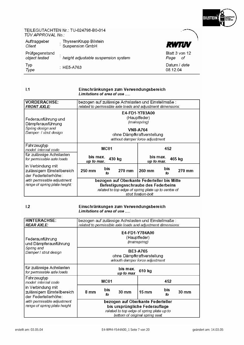
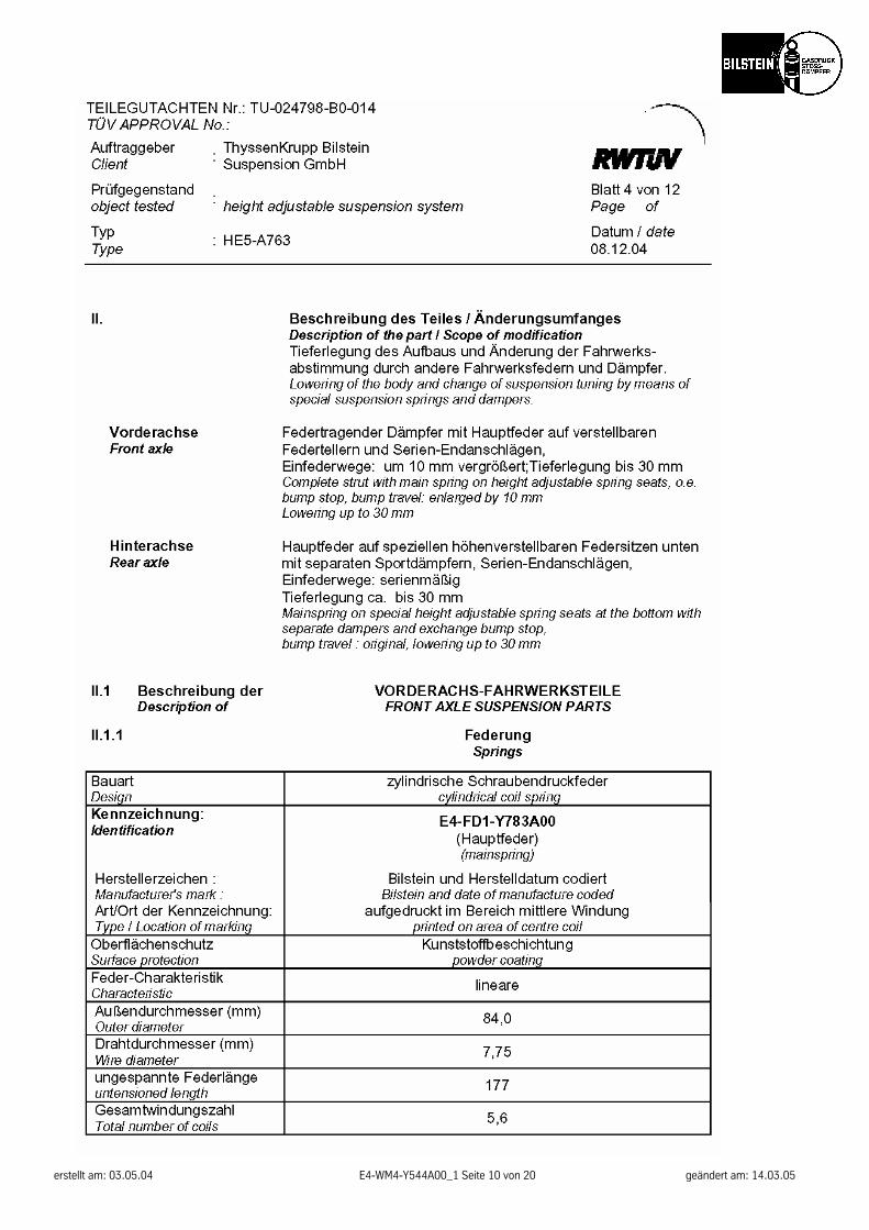
I. FRONT spring part number main spring
E4-FD1-Y783A00 shock absorber part number
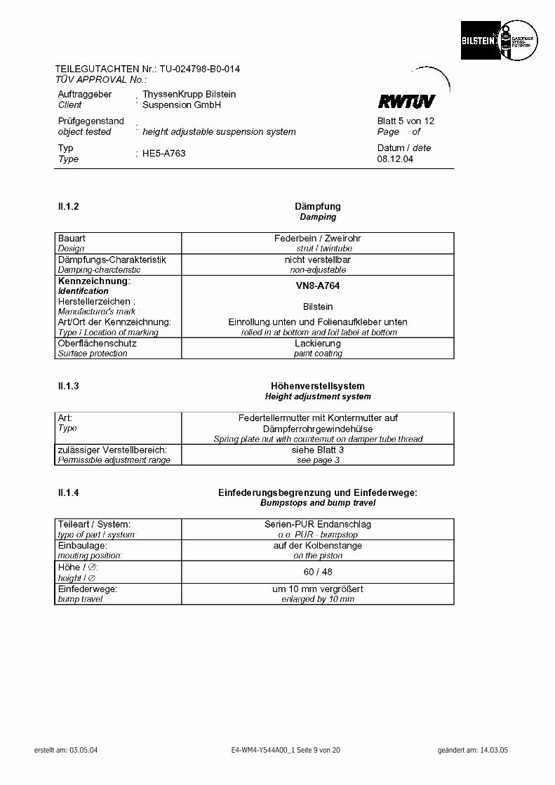
VN8-A764 without damping force adjustment
maximum permissible axle load
MC01 430 kg= 946 lb
452 465 kg= 1023 lb
permissible adjustment range
250 – 270 mm*= 20 mm range
260 – 270 mm*= 10 mm range
* measurement: top edge of spring seat down to the center of bottom mounting screw
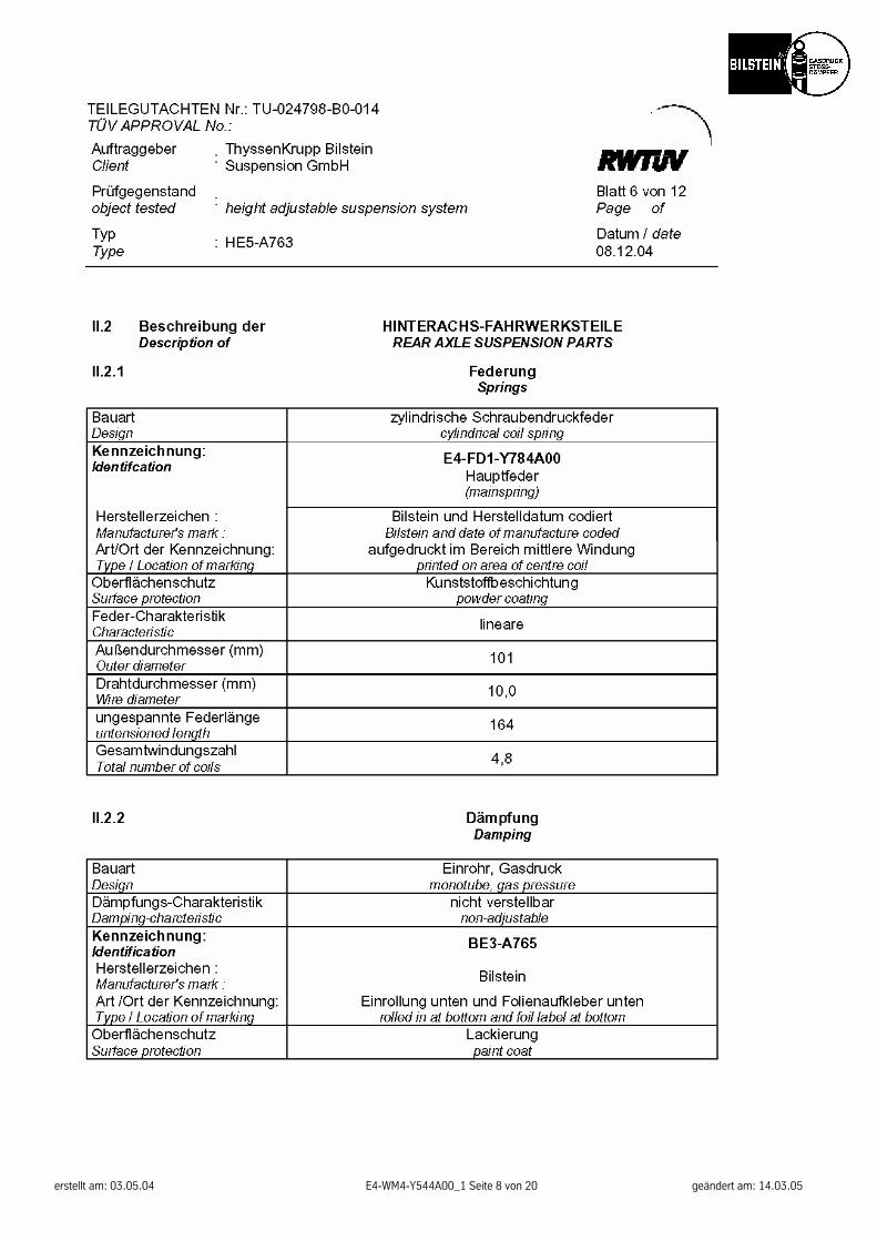
REAR maximum permissible axle load 610 kg ( 1342 lb) spring part number main spring
E4-FD1-Y784A00 shock absorber part number
BE3-A765 without damping force
adjustment permissible adjustment range
MC01 8 - 30 mm*
= 22 mm range
452 15 - 30 mm*
= 15 mm range * measurement:
top edge of spring seat down to original spring seat
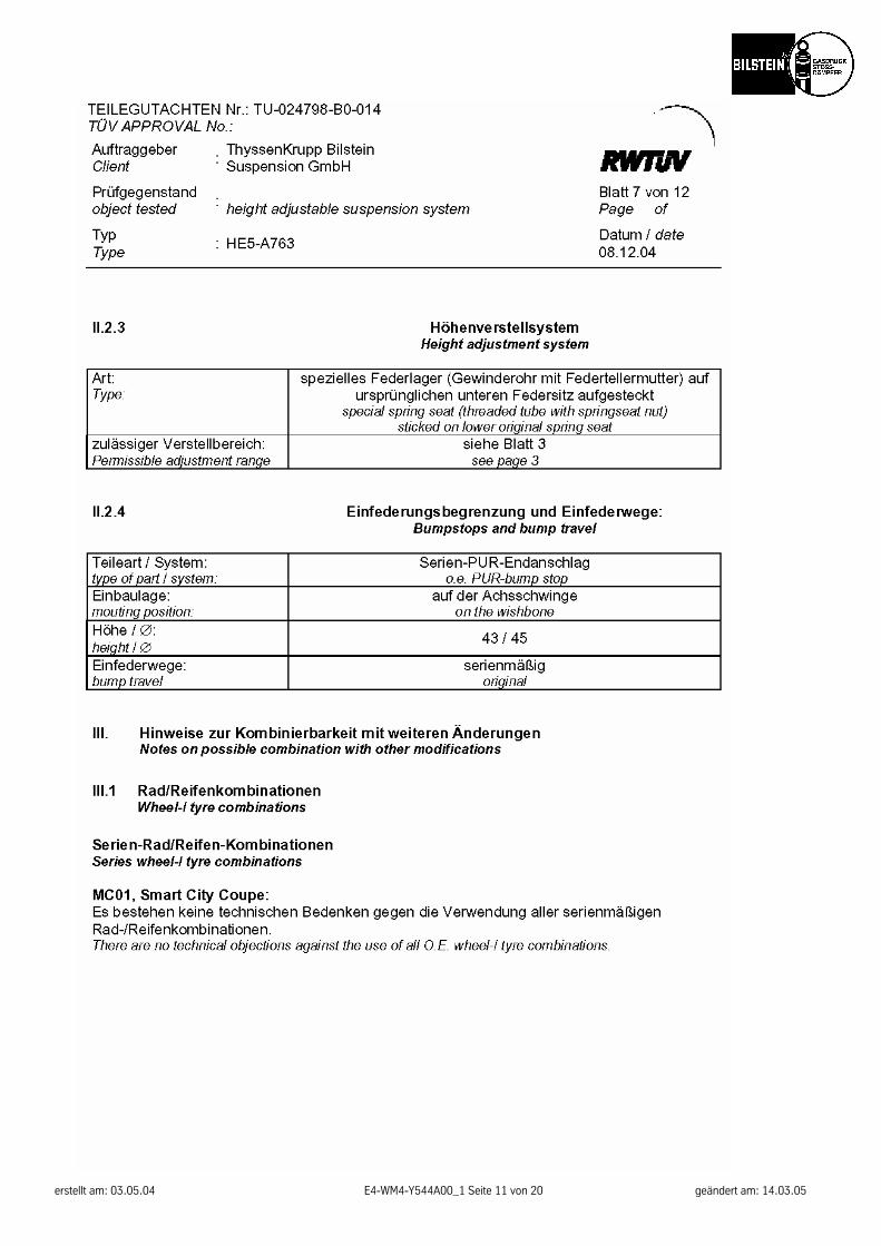
MC01, Smart City Coupe: There are no technical objections against the use of all O.E. wheel/tyre combinations.
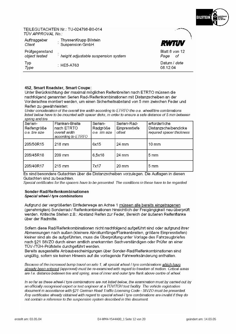
452, Smart Roadster, Smart Coupe:
Under concideration of the overall tire width according to ETRTO the o.e. wheell/tire combinations listed below have to be mounted with spacer disks, in order to ensure a safe distance of 5 mm between spring and tire
o.e. tire size overall width acc. to ETRTO
o.e. rim size offset required spacer thickness
205/50R15 218 mm 6x15 24 mm 10 mm 205/45R16 209 mm 6,5x16 24 mm 5 mm 205/40R17 215 mm 7x17 20 mm 5 mm Special certificates for the spacers have to be presented. The conditions in these have to be regarded.
Because of the increased bump travel on axle 1, all special wheel/tyre combinations which have already been entered ( approved) must be re-examined with regard to freedom of motion. Critical areas are f.e. area of in-ner and outer tyre flank above centre of wheel.
In so far as these wheel-/ tyre combinations are not listed below, the examination must by carried out by an officially recognised expert or test engineer at a TÜV/TÜH test facility. The vehicle registration document in ac-cordance with §21 German Road Traffic Licensing Code - StVZO must be presented. Any certificates already
erstellt am: 03.05.04 E4-WM4-Y544A00_1 Seite 18 von 20 geändert am: 14.03.05
obtained with regard to special wheel/tyre combinations are invalid if they do not contain a reference to the suspension system described in this document.
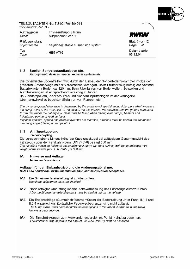
The dynamic ground clearance is decreased by the provision of special springs/dampers which increase the bump travel of the front and rear axle. In the case of the test vehicle, the distance from the ground amounted to 120 mm under the motor crossbar. Care must be taken when driving over humps, barriers and heightened paving or road surfaces. If special spoilers, aprons and exhaust systems are mounted, attention must be paid to the decreased overhang angle (driving up ramps etc.).
The specified minimum height of the coupling ball above the road surface with the permissible total weight of the vehicle (acc. DIN 74058) is 350 mm.
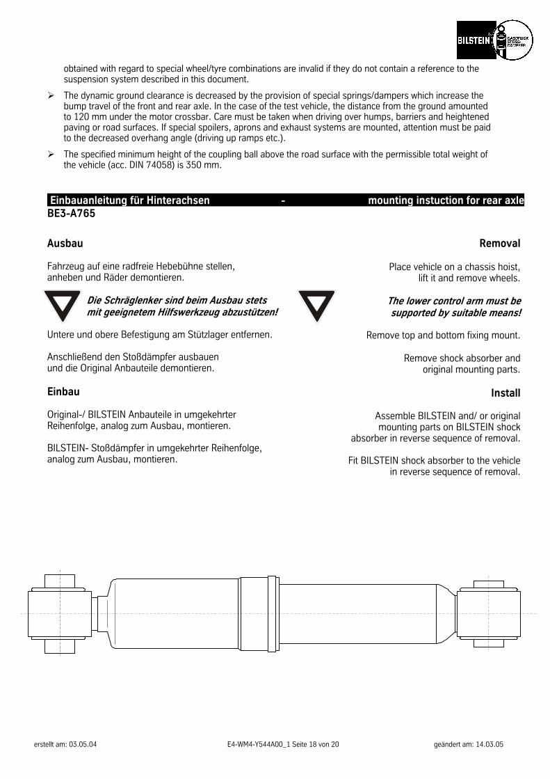
Einbauanleitung für Hinterachsen - mounting instuction for rear axle BE3-A765
Ausbau Fahrzeug auf eine radfreie Hebebühne stellen, anheben und Räder demontieren.
Die Schräglenker sind beim Ausbau stets mit geeignetem Hilfswerkzeug abzustützen!
Untere und obere Befestigung am Stützlager entfernen. Anschließend den Stoßdämpfer ausbauen und die Original Anbauteile demontieren. Einbau Original-/ BILSTEIN Anbauteile in umgekehrter Reihenfolge, analog zum Ausbau, montieren. BILSTEIN- Stoßdämpfer in umgekehrter Reihenfolge, analog zum Ausbau, montieren.
Removal
Place vehicle on a chassis hoist, lift it and remove wheels.
The lower control arm must be supported by suitable means!
Remove top and bottom fixing mount.
Remove shock absorber and
original mounting parts.
Install
Assemble BILSTEIN and/ or original mounting parts on BILSTEIN shock
absorber in reverse sequence of removal.
Fit BILSTEIN shock absorber to the vehicle in reverse sequence of removal.
erstellt am: 03.05.04 E4-WM4-Y544A00_1 Seite 19 von 20 geändert am: 14.03.05
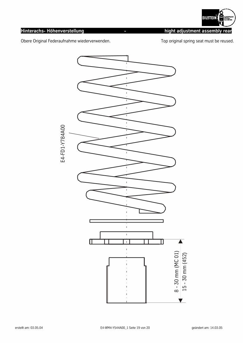
Hinterachs- Höhenverstellung - hight adjustment assembly rear Obere Original Federaufnahme wiederverwenden. Top original spring seat must be reused.
E4-F
D1-
Y784
A00
8 -
30 m
m (M
C 0
1)
15 -
30
mm
(452
)

erstellt am: 03.05.04 E4-WM4-Y544A00_1 Seite 20 von 20 geändert am: 14.03.05
ThyssenKrupp Bilstein Suspension GmbH August-Bilstein-Str. 4, 58256 Ennepetal
Postfach 11 51, 58240 Ennepetal Telefon: (0 23 33) 791-0, Telefax: (0 23 33) 7 91- 4900
Hotline: 01805- 600- 860; Internet: www.bilstein.de