Embed Size (px)
Citation preview
ISTRUZIONI E AVVERTENZE PER L’INSTALLATORE • INSTRUCTIONS AND RECOMMENDA-TIONS FOR THE INSTALLER • ANWEISUNGEN UND HINWEISE FÜR DEN INSTALLATEUR
• INSTRUCTIONS ET AVERTISSEMENTS POUR L’INSTALLATEUR • INSTRUCCIONES Y ADVERTENCIAS PARA EL INSTALADOR
• INSTRUÇÕES E AVISOS PARA O INSTALADOR
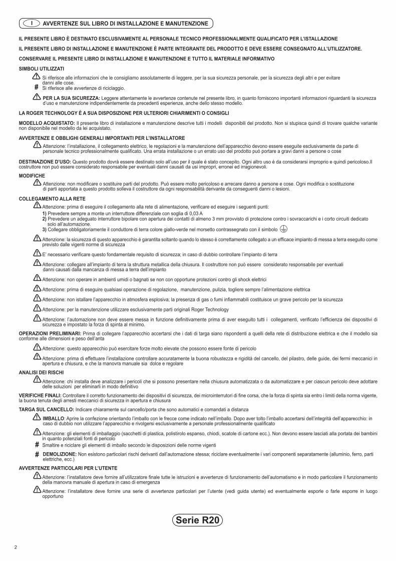
Serie R20
AUTOMAZIONI PER CANCELLI A BATTENTE • SWING GATES AUTOMATION • AUTOMATISIERUNG FÜR DREHTORE • AUTOMATISME POUR PORTAILS À BATTANT
• AUTOMATISMOS PARA CANCELAS BATIENTES • AUTOMAÇÕES PARA PORTÕES DE BATENTE
IS10 Rev.0102/09/2009
Serie R20 2
AVVERTENZE SUL LIBRO DI INSTALLAZIONE E MANUTENZIONE
IL PRESENTE LIBRO È DESTINATO ESCLUSIVAMENTE AL PERSONALE TECNICO PROFESSIONALMENTE QUALIFICATO PER L’ISTALLAZIONE
IL PRESENTE LIBRO DI INSTALLAZIONE E MANUTENZIONE È PARTE INTEGRANTE DEL PRODOTTO E DEVE ESSERE CONSEGNATO ALL’UTILIZZATORE.
CONSERVARE IL PRESENTE LIBRO DI INSTALLAZIONE E MANUTENZIONE E TUTTO IL MATERIALE INFORMATIVO
SIMBOLI UTILIZZATI
Si riferisce alle informazioni che le consigliamo assolutamente di leggere, per la sua sicurezza personale, per la sicurezza degli altri e per evitare danni alle cose.Si riferisce alle avvertenze di riciclaggio.
PER LA SUA SICUREZZA: Leggere attentamente le avvertenze contenute nel presente libro, in quanto forniscono importanti informazioni riguardanti la sicurezza d’uso e manutenzione indipendentemente da precedenti esperienze, anche dello stesso modello.
LA ROGER TECHNOLOGY È A SUA DISPOSIZIONE PER ULTERIORI CHIARIMENTI O CONSIGLI
MODELLO ACQUISTATO: Il presente libro di installazione e manutenzione descrive tutti i modelli disponibili del prodotto. Non si stupisca quindi di trovare qualche variante non disponibile nel modello da lei acquistato.
AVVERTENZE E OBBLIGHI GENERALI IMPORTANTI PER L’INSTALLATORE Attenzione: l’installazione, il collegamento elettrico, le regolazioni e la manutenzione dell’apparecchio devono essere eseguite esclusivamente da parte di personale tecnico professionalmente qualificato. Una errata installazione o un errato uso del prodotto può portare a gravi danni a persone o cose
DESTINAZIONE D’USO: Questo prodotto dovrà essere destinato solo all’uso per il quale è stato concepito. Ogni altro uso è da considerarsi improprio e quindi pericoloso.Il costruttore non può essere considerato responsabile per eventuali danni causati da usi impropri, erronei ed irragionevoli.
MODIFICHE Attenzione: non modificare o sostituire parti del prodotto. Può essere molto pericoloso e arrecare danno a persone e cose. Ogni modifica o sostituzione di parti apportata a questo prodotto solleva il costruttore da ogni responsabilità derivante da conseguenti danni o lesioni.
COLLEGAMENTO ALLA RETE
Attenzione: prima di eseguire il collegamento alla rete di alimentazione, verificare ed eseguire i seguenti punti:1) Prevedere sempre a monte un interruttore differenziale con soglia di 0,03 A
2) Prevedere un adeguato interruttore bipolare con apertura dei contatti di almeno 3 mm provvisto di protezione contro i sovraccarichi e i corto circuiti dedicato solo all’automazione.
3) Collegare obbligatoriamente il conduttore di terra colore giallo-verde nel morsetto contrassegnato con il simbolo
Attenzione: la sicurezza di questo apparecchio è garantita soltanto quando lo stesso è correttamente collegato a un efficace impianto di messa a terra eseguito come previsto dalle vigenti norme di sicurezza
E’ necessario verificare questo fondamentale requisito di sicurezza; in caso di dubbio controllare l’impianto di terra
Attenzione: collegare all’impianto di terra la struttura metallica della chiusura. Il costruttore non può essere considerato responsabile per eventuali danni causati dalla mancanza di messa a terra dell’impianto
Attenzione: non operare in ambienti umidi o bagnati se non con opportune protezioni contro gli shock elettrici
Attenzione: prima di eseguire qualsiasi operazione di regolazione, manutenzione, pulizia, togliere sempre l’alimentazione elettrica
Attenzione: non istallare l’apparecchio in atmosfera esplosiva; la presenza di gas o fumi infiammabili costituisce un grave pericolo per la sicurezza
Attenzione: per la manutenzione utilizzare esclusivamente parti originali Roger Technology
Attenzione: l’automazione non deve essere messa in funzione definitivamente prima di aver eseguito tutti i collegamenti, verificato l’efficienza dei dispositivi di sicurezza e impostato la forza di spinta al minimo.
OPERAZIONI PRELIMINARI: Prima di collegare l’apparecchio accertarsi che i dati di targa siano rispondenti a quelli della rete di distribuzione elettrica e che il modello sia conforme alle dimensioni e peso dell’anta
Attenzione: questo apparecchio può esercitare forze molto elevate che possono essere fonte di pericolo
Attenzione: prima di effettuare l’installazione controllare accuratamente la buona robustezza e rigidità del cancello, del pilastro, delle guide, dei fermi meccanici in apertura e chiusura, e che la manovra manuale sia dolce e regolare
ANALISI DEI RISCHI
Attenzione: chi installa deve analizzare i pericoli che si possono presentare nella chiusura automatizzata o da automatizzare e per ciascun pericolo deve adottare delle soluzioni per eliminarli in modo definitivo
VERIFICHE FINALI: Controllare il corretto funzionamento dei dispositivi di sicurezza, dei microinterrutori di fine corsa, che la forza di spinta sia entro i limiti della norma vigente, la buona tenuta degli arresti meccanici di sicurezza in apertura e chiusura
TARGA SUL CANCELLO: Indicare chiaramente sul cancello/porta che sono automatici e comandati a distanza
IMBALLO: Aprire la confezione orientando l’imballo con le frecce come indicato nell’imballo. Dopo aver tolto l’imballo accertarsi dell’integrità dell’apparecchio: in caso di dubbio non utilizzare l’apparecchio e rivolgersi esclusivamente a personale professionalmente qualificato
Attenzione: gli elementi di imballaggio (sacchetti di plastica, polistirolo espanso, chiodi, scatole di cartone ecc.). Non devono essere lasciati alla portata dei bambini in quanto potenziali fonti di pericoloSmaltire e riciclare gli elementi di imballo secondo le disposizioni delle norme vigenti
DEMOLIZIONE: Non esistono particolari rischi derivanti dall’automazione stessa; riciclare eventualmente i vari componenti separatamente (alluminio, ferro, parti elettriche, ecc.)
AVVERTENZE PARTICOLARI PER L’UTENTE
Attenzione: l’installatore deve fornire all’utilizzatore finale tutte le istruzioni e avvertenze di funzionamento dell’automatismo e in modo particolare il funzionamento della manovra manuale di apertura in caso di emergenza
Attenzione: l’installatore deve fornire una serie di avvertenze particolari per l’utente (vedi guida utente) ed eventualmente esporle o farle esporre in luogo opportuno
!
!
!
!
!
!
!
!
!
!
!
!!
!!
!
!
!
!
!
I
##
#
Serie R20
RECOMMENDATIONS REGARDING THE INSTALLATION AND MAINTENANCE BOOKLET
THIS BOOKLET IS INTENDED SOLELY FOR PROFESSIONALLY QUALIFIED INSTALLERS
THIS INSTALLATION AND MAINTENANCE BOOKLET IS AN INTEGRAL PART OF THE PRODUCT AND MUST BE GIVEN TO THE USER.
KEEP THIS INSTALLATION AND MAINTENANCE BOOKLET TOGETHER WITH ALL THE INFORMATIVE MATERIAL
SYMBOLS USED IN THE BOOKLET
Referred to information that must be read for your own safety and that of others and to avoid damage to property.Referred to recommendations for recycling
FOR YOUR SAFETY: Carefully read the recommendations and warnings contained in this booklet since they give important information regarding safety of use and maintenance, regardless of whether you have previous experience with the same model or not,
PLEASE DO NOT HESITATE TO GET IN TOUCH WITH ROGER TECHNOLOGY FOR FURTHER EXPLANATIONS OR ADVICE
PURCHASED MODEL: This installation and maintenance booklet describes all the available models of the product. You may therefore find some information regarding a variation that is not available on the model you have purchased.
IMPORTANT GENERAL RECOMMENDATIONS AND OBLIGATIONS FOR THE INSTALLER
Caution: only professionally qualified technicians must carry out installation, electrical connections, adjustments and maintenance on the system. Incorrect installation or misuse of the product could lead to severe injury to persons or serious damage to property.
END USE
This product must only be used for the purpose for which it has been designed. Any other use is to be considered improper and therefore dangerous. The manufacturer cannot be held liable for any injury or damage caused by inappropriate, incorrect or unreasonable use.
ALTERATIONS
Caution: do not alter or replace product parts. It could be highly dangerous and cause injury to persons and damage to property. Any alteration or replacement of parts made on this product relieves the manufacturer of all and any liability for resulting damage or injury.
CONNECTION TO THE MAINS ELECTRICITY SUPPLY
Caution: before connecting to the mains electricity supply, check and proceed as follows:
1) always ensure there is a residual current circuit breaker with 0.03 A threshold installed between the equipment and the mains power outlet; 2) install a suitable double-pole linked switch having a contact separation of at least 3 mm in both poles with overload and short circuit protection and dedicated to the automation; 3) the yellow-green earth wire must be connected to the terminal marked with the symbol
Caution: the safety of this equipment is only guaranteed when it is effectively earthed in conformity with current safety standards and regulations
This fundamental safety requirement must be checked; if in doubt, check the earthing system
Caution: connect the metal framework of the gate/door to the earthing system
The manufacturer cannot be held liable for any damage or injury caused by failure to earth the installation
Caution: do not work in wet or damp environments without having taken suitable precautions against electric shock
Caution: always cut off the power supply before carrying out any adjustment, maintenance or cleaning
Caution: do not install the equipment in an explosive atmosphere; the presence of flammable gases or fumes is a safety hazard
Caution: only use original Roger Technology parts when required during maintenance
Caution: ensure that all the connections have been made, the efficiency of the safety devices checked and the thrust force set to minimum before the automation is put into normal use.
PRELIMINARY OPERATIONS: Before connecting the equipment to the power supply, ensure that the data stamped on the rating plate correspond to those of the mains electricity supply and that the model conforms to the size and weight of the gate
Caution: this equipment may exert very high forces that could be a source of danger
Caution: before carrying out the installation, carefully check that the gate, post, guides and gate stops for open and close positions are robust and firm and that manually-operated movements are smooth and regular
RISK ANALYSIS
Caution: the installer must analyse the risks that can be present with a gate/door that is automated or to be automated and must find solutions to eliminate each and every hazard
FINAL CHECKS: Check correct operation of the safety devices and the limit microswitches, check that the thrust force is within the limits recommended by current regulations and check that the safety stops for the open and close positions are firmly fixed
GATE/DOOR RATING PLATE: Clearly indicate on the gate/door that it is automatic and remote controlled
PACKAGING: Place the pack according to the arrows on the packaging and then remove the packaging. Check that the equipment is intact and undamaged; if in doubt do not use the equipment and contact only professionally qualified persons
Caution: the packaging (plastic bags, polystyrene foam, nails, cardboard boxes, etc.) must not be left within each of children since it is a potential source of danger
Dispose of or recycle the packaging in accordance with current applicable legislation
DEMOLITION: There are no particular risks from the automation system itself; if possible recycle the various parts separately (aluminium, iron, electrical parts, etc.)
SPECIAL RECOMMENDATIONS FOR THE USER
Caution: the installer must give the end user all the automation system operating instructions and warnings and in particular those concerning the emergency override for manual opening
Caution: the installer must provide a set of special warnings for the user (see user guide) and if necessary display them or have them displayed in a suitable place
3
GB
!
!
!
!
!
!
!!!!!!!!!
!
!
!
!
!
!
!
##
#
4
Serie R20
HINWEISE ZUM INSTALLATIONS- UND WARTUNGSHANDBUCH
VORLIEGENDES HANDBUCH IST AUSSCHLIEßLICH FÜR QUALIFIZIERTE INSTALLATIONSTECHNIKER VORGESEHEN.VORLIEGENDES INSTALLATIONS- UND WARTUNGSHANDBUCH IST BESTANDTEIL DES PRODUKTS UND MUSS DEM BENUTZER AUSGEHÄNDIGT WERDEN.VORLIEGENDES INSTALLATIONS- UND WARTUNGSHANDBUCH UND DAS SÄMTLICHES INFORMATIONSMATERIAL AUFBEWAHREN.VERWENDETE SYMBOLE
Weist auf Informationen hin, die Sie zu Ihrer persönlichen Sicherheit, zur Sicherheit anderer Personen und zum Vermeiden von Sachschäden unbedingt lesen sollten.Weist auf Hinweise bezüglich des Recyclings hin.
FÜR IHRE SICHERHEIT:Aufmerksam die in vorliegendem Handbuch enthaltenen Hinweise lesen. Sie erteilen wichtige Informationen bezüglich der Sicherheit für Betrieb und Wartung. Dies gilt auch dann, wenn Sie bereits Erfahrung, auch mit dem gleichen Modell, haben.
DAS UNTERNEHMEN ROGER TECHNOLOGY STEHT FÜR WEITERE INFORMATIONEN ODER RATSCHLÄGE JEDERZEIT ZU IHRER VERFÜGUNG.
ERWORBENES MODELL: Vorliegendes Installations- und Wartungshandbuch beschreibt alle verfügbaren Produktmodelle. Wundern Sie sich daher nicht, sollten Sie auf eine Variante stoßen, die bei dem von Ihnen erworbenen Produkt nicht vorhanden ist.
WICHTIGE HINWEISE UND ALLGEMEINE PFLICHTEN DES INSTALLATEURS
Achtung: Das Aufstellen, der elektrische Anschluss, die Einstellung und die Wartung der Anlage darf ausschließlich von qualifiziertem Fachpersonal vorgenommen werden. Eine falsche Montage oder eine falsche Verwendung des Produkts kann schwere Personen- oder Sachschäden zur Folge haben.
VERWENDUNGSZWECK
Dieses Produkt darf ausschließlich zu dem Zweck verwendet werden, für den es konzipiert wurde. Jede andere Verwendung gilt als missbräuchlich und somit gefährlich. Der Hersteller übernimmt keine Haftung für etwaige Schäden, die durch missbräuchliche, unsachgemäße oder unvernünftige Verwendung verursacht wurden.
ÄNDERUNGEN
Achtung: Keine Teile des Produkts ändern oder auswechseln. Dies kann sehr gefährlich sein und Personen-oder Sachschäden hervorrufen. Jede Änderung oder Austausch von Bauteilen, die an diesem Produkt vorgenommen werden, befreit den Hersteller von jeder Haftung im Zusammenhang mit sich daraus ergebenden Schäden oder Verletzungen.
NETZANSCHLUSS
Achtung: Bevor der Netzanschluss vorgenommen wird, folgende Punkte kontrollieren und durchführen:
1) Immer einen Differentialschalter mit einer Schwelle von 0,03 A vorschalten. 2) Einen nur für den Automatismus vorgesehenen geeigneten bipolaren Schalter, mit einer Kontaktöffnung von mindestens 3 mm, installieren, der mit einer Schutzvorrichtung gegen Überlastungen und gegen Kurzschluss versehen ist. 3) Die gelb-grüne Erdleitung muss an die mit dem entsprechenden Symbol gekennzeichnete Klemme angeschlossen werden
Achtung: Die Sicherheit dieser Anlage ist nur dann gewährleistet, wenn sie korrekt an eine funktionstüchtige, entsprechend der geltenden Sicherheitsbestimmungen ausgeführte Erdungsanlage, angeschlossen ist.
Es ist absolut erforderlich, diese wesentliche Sicherheitsanforderung sicherzustellen. Im Zweifelsfall, die Erdungsanlage kontrollieren.
Achtung: Die Metallstruktur der Schließvorrichtung an die Erdungsanlage anschließen. Der Hersteller haftet nicht für etwaige Schäden, die durch eine fehlende Erdung der Anlage verursacht wurden.
Achtung: Nicht ohne entsprechende Schutzvorrichtungen gegen Elektroschocks in feuchter oder nasser Umgebung arbeiten.
Achtung: Vor dem Durchführen von jeglichen Einstellungen, Wartungseingriffen oder Reinigungsarbeiten, grundsätzlich die Stromversorgung unterbrechen.
Achtung: Die Anlage nicht in explosionsgefährdeter Umgebung aufstellen. Das Vorhandensein von entflammbaren Gasen oder Rauch stellt eine große Gefahr für die Sicherheit dar.
Achtung: Für die Wartung ausschließlich Originalteile von Roger Technology verwenden.
Achtung: Die automatische Anlage darf nicht endgültig in Betrieb genommen werden, bevor sämtliche Anschlüsse vorgenommen wurden, die Funktionstüchtigkeit der Sicherheitsvorrichtungen kontrolliert und die Schubkraft auf das Minimum eingestellt wurde.
VORBEREITENDE ARBEITEN: Vor dem Anschließen der Anlage sicherstellen, dass die Daten auf dem Typenschild mit den Daten des Stromnetzes übereinstimmen und dass das Modell den Abmessungen und dem Gewicht des Tors entspricht.
Achtung: Diese Anlage kann sehr hohe Kräfte entwickeln, die eine Gefahrenquelle darstellen können.Achtung: Vor der Installation sorgfältig überprüfen, ob das Tor, der Steher, die Führungen, die mechanischen Öffnungs- und Schließ-Endanschläge ausreichend robust und solide sind und ob der manuelle Bewegungsvorgang weich und regelmäßig von statten geht.
GEFAHRENEINSCHÄTZUNG
Achtung: Die die Installation ausführende Person muss die Gefahren abschätzen, die beim automatischen oder zu automatisierenden Schließen auftreten können und muss alle erforderlichen Maßnahmen ergreifen, um diese Gefahren dauerhaft zu beseitigen.
ENDKONTROLLEN: Die Funktionstüchtigkeit der Sicherheitsvorrichtungen und der Endanschlag-Mikroschalter kontrollieren, sicherstellen, dass die Schubkraft innerhalb der geltenden Bestimmungen liegt und dass die mechanischen Sicherheits-Haltevorrichtungen beim Öffnen und schließen fest angebracht sind.
TOR-SCHILD: Am Tor/Tür deutlich anzeigen, dass diese automatisiert und ferngesteuert sind.
VERPACKUNG:Die Verpackung entsprechend der auf der Verpackung angezeigten Pfeilen ausrichten und dann öffnen. Nachdem die Verpackung entfernt wurde,sicherstellen, dass das ! Gerät nicht beschädigt ist: im Zweifelsfall das Gerät nicht benutzen und sich ausschließlich an qualifiziertes Fachpersonal wenden.
Achtung: Das Verpackungsmaterial (Plastiktüten, Polystyren-Schaumstoff, Nägel, Pappschachteln, usw.) dürfen nicht für Kinder zugänglich sein, da sie eine potentielle Gefahrenquelle darstellen. Das Verpackungsmaterial entsprechend der geltenden Bestimmungen entsorgen und recyceln.
VERSCHROTTUNG: Es bestehen keine besonderen Risiken im Zusammenhang mit der Automatisierung. Gegebenenfalls die verschiedenen Bauteile getrennt recyceln (Aluminium, Eisen, elektrische Komponenten, usw.).
BESONDERE HINWEISE FÜR DEN BENUTZER
Achtung: Der Installateur muss dem Endverbraucher sämtliche Anweisungen und Hinweise zur Funktionsweise der Automatisierung überlassen. Dazu gehören insbesondere die Anweisungen zur manuellen Notentriegelung.
Achtung: Der Installateur muss den Benutzer über eine Reihe von besonderen Hinweisen (siehe Benutzerhandbuch) in Kenntnis setzen und diese gegebenenfalls an geeignetem Ort vortragen oder vortragen lassen.
D
!
!
!
!
!
!
!
!!
!!!
!!
!
!
!
!
!
!
#
#
!
#
5
Serie R20
AVERTISSEMENTS CONCERNANT LE MANUEL D’INSTALLATION ET DE MAINTENANCE
CE MANUEL N’EST DESTINÉ QU’À DU PERSONNEL QUALIFIÉ SPÉCIALISÉ DANS L’INSTALLATION
CE MANUEL D’INSTALLATION ET DE MAINTENANCE FAIT PARTIE INTÉGRANTE DU PRODUIT ET DOIT ÊTRE REMIS À L’USAGER.
CONSERVER CE MANUEL D’UTILISATION ET MAINTENANCE AINSI QUE TOUT LE MATÉRIEL D’INFORMATION.
SYMBOLES UTILISÉS
Se réfère aux informations qu’il est indispensable de lire pour votre sécurité personnelle, pour la sécurité des autres et pour éviter des dommages matériels.Se réfère aux avertissements concernant le recyclage.
CONSIGNES DE SÉCURITÉ: Même si vous avez déjà l’expérience de ce type de produits, éventuellement du même modèle, lire attentivement les avertissements contenus dans ce manuel dans la mesure où ils fournissent des informations importantes concernant la sécurité.
LA ROGER TECHNOLOGY EST À VOTRE DISPOSITION POUR TOUTE AUTRE INFORMATION OU CONSEIL QUE VOUS POURRIEZ DÉSIRER.
MODÈLE ACHETÉ: Ce manuel d’installation et de maintenance décrit tous les modèles disponibles du produit. Il est donc possible que certaines variantes ne soient pas disponibles sur le modèle que vous venez d’acheter.
AVERTISSEMENTS ET OBLIGATIONS GÉNÉRALES IMPORTANTES POUR L’INSTALLATEUR
Attention: l’installation, la connexion électrique, les réglages et la maintenance de l’appareil ne doivent être effectués que par du personnel qualifié spécialisé dans l’installation. Une erreur d’installation ou un mauvais usage du produit peut provoquer des dommages corporels et matériels graves.
USAGE AUQUEL LE PRODUIT EST DESTINÉ
Ce produit ne devra être destiné qu’à l’usage pour lequel il a été conçu. Tout autre usage doit être considéré impropre et donc dangereux. Le constructeur ne peut être tenu responsable des dommages provoqués par un usage impropre, erroné ou déraisonnable.
MODIFICATIONS
Attention: ne pas modifier ou remplacer des parties du produit. Cela peut être très dangereux et provoquer des dommages corporels et matériels graves. Le constructeur ne peut être tenu responsable de toute modification ou tout remplacement effectués sur ce produit et ayant entraîné d’éventuels dommages ou lésions.
CONNEXION AU RÉSEAU
Attention: Avant d’effectuer la connexion au réseau électrique, contrôler les points suivants :
1) prévoir toujours en amont un interrupteur différentiel avec une seuil de 0,03 A 2) prévoir un interrupteur bipolaire adapté, ayant une ouverture des contacts d’au moins 3 mm et pourvu de protection contre les surcharges et les courts-circuits, uniquement réservé à l’automation. 3) connecter obligatoirement le conducteur de terre couleur jaune-vert dans la borne pourvue du symbole
Attention: la sécurité de cet appareil n’est garantie que lorsque ce dernier est correctement connecté à une installation efficace de mise à la terre effectuée selon les normes de sécurité en vigueur.
Cette règle fondamentale de sécurité doit absolument être appliquée; en cas de doute, contrôler l’installation de terre.
Attention: connecter à l’installation de terre la structure métallique de fermeture du portail/de la porte.
Le constructeur ne peut être considéré responsable des éventuels dommages provoqués par une absence demise à la terre de l’installation.
Attention: ne travailler dans des lieux humides ou mouillés qu’avec une protection appropriée contre les chocsélectriques.
Attention: couper toujours le courant avant d’effectuer toute opération de réglage, maintenance ou nettoyage.
Attention: ne jamais installer l’appareil dans une atmosphère explosive: la présence de gaz ou de fumées inflammables constitue un grave danger.
Attention: n’utiliser pour la maintenance que des pièces originales Roger Technology
Attention: ne mettre définitivement en fonction l’automation qu’après avoir effectué toutes les connexions, contrôlé l’efficacité des dispositifs de sécurité et réglé la force de poussée au minimum.
OPÉRATIONS PRÉLIMINAIRES: Avant de connecter l’appareil, s’assurer que les données de la plaque correspondent bien à celles du réseau de distribution électrique et que le modèle soit conforme aux dimensions et au poids du portail
Attention: cet appareil est en mesure d’exercer des forces très importantes qui peuvent être très dangereuses.Attention: avant d’effectuer l’installation, s’assurer de la robustesse et de la rigidité du portail, du pilier, des rails, des arrêts mécaniques en ouverture et en fermeture et que la manœuvre manuelle soit douce et régulière.
ANALYSES DES RISQUES
Attention: l’installateur doit analyser les dangers qui peuvent se présenter durant la fermeture automatisée ou à automatiser et doit trouver, pour chaque danger, des solutions permettant de les éliminer définitivement.
VÉRIFICATIONS FINALES: Contrôler le bon fonctionnement des dispositifs de sécurité, des micro-interrupteurs de fin de course, la bonne tenue des arrêts mécaniques de sécurité en ouverture et fermeture et que la force de poussée soit dans les limites requises par la loi en vigueur.
PLAQUE SUR LE PORTAIL: Indiquer clairement sur le portail/la porte qu’ils sont automatiques et commandés à distance
EMBALLAGE:Enlever l’emballage en respectant le sens indiqué par les flèches. Après avoir enlevé l’emballage s’assurer que l’appareil est en bon état: en cas de doute, ne pas utiliser ce dernier et s’adresser à du personnel qualifié.
Attention: les éléments qui composent l’emballage (sacs en plastique, polystyrène expansé, clous, boîtes en carton, etc.) peuvent être sources de danger et donc ne doivent pas être laissés à la portée des enfants.Eliminer ou recycler les éléments de l’emballage conformément aux normes en vigueur.
DÉMOLITION: L’automation même ne présente pas de dangers particuliers; recycler éventuellement séparément les divers composants (aluminium, fer, parties électriques, etc.).
AVERTISSEMENTS PARTICULIERS POUR L’UTILISATEUR
Attention: l’installateur doit fournir à l’utilisateur final toutes les instructions et avertissements concernant le fonctionnement de l’automatisme et tout particulièrement le fonctionnement de la manœuvre manuelle d’ouverture en cas d’urgence.
Attention: l’installateur doit fournir une série d’avertissements particuliers à l’utilisateur (voir guide usager) et éventuellement les exposer ou les faire exposer dans un lieu opportun.
F
!
!
!
!
!
!
!
!!!!!!!!
!
!
!
!
!
!
!
##
#
6
Serie R20
ADVERTENCIAS SOBRE EL MANUAL DE INSTALACIÓN Y MANTENIMIENTO
EL PRESENTE MANUAL ESTÁ DESTINADO EXCLUSIVAMENTE A PERSONAL TÉCNICO PROFESIONALMENTE CUALIFICADO PARA LA INSTALACIÓN.
ESTE MANUAL DE INSTALACIÓN Y MANTENIMIENTO ES PARTE INTEGRANTE DEL PRODUCTO Y DEBE ENTREGARSE AL USUARIO.
CONSERVE ESTE MANUAL DE INSTALACIÓN Y MANTENIMIENTO Y TODO EL MATERIAL INFORMATIVO.
SÍMBOLOS UTILIZADOS
Se refiere a las informaciones que conviene que lea absolutamente, para su seguridad personal, para la seguridad de los demás y para evitar daños a las cosas.Se refiere a las advertencias de reciclaje.
PARA SU SEGURIDAD:Lea atentamente las advertencias contenidas en el presente manual, ya que proporcionan importantes informaciones relativas a la seguridad de uso y mantenimiento, independientemente de anteriores experiencias incluso del mismo modelo.
ROGER TECHNOLOGY ESTÁ A SU DISPOSICIÓN PARA ULTERIORES ACLARACIONES O CONSEJOS.
MODELO ADQUIRIDO: Este manual de instalación y mantenimiento describe todos los modelos disponibles del producto. Así pues, no se sorprenda si encuentra alguna variante no disponible en el modelo que usted ha adquirido.
ADVERTENCIAS Y OBLIGACIONES GENERALES IMPORTANTES PARA EL INSTALADOR
Atención: la instalación, la conexión eléctrica, las regulaciones y el mantenimiento del aparato deben ser realizados exclusivamente por personal técnico profesionalmente cualificado. Una instalación equivocada o un uso incorrecto del producto puede ocasionar graves daños a personas o cosas.
USO PREVISTO
Este producto deberá destinarse únicamente al uso para el cual ha sido concebido. Cualquier otro uso ha de considerarse impropio y, por tanto, peligroso. El constructor no puede considerarse responsable por eventuales daños causados por usos impropios, incorrectos e irrazonables.
MODIFICACIONES
Atención: No modifique o sustituya partes del producto: puede ser muy peligroso y ocasionar daños a personas y cosas. Cualquier modificación o sustitución de partes aportada a este producto exime al constructor de toda responsabilidad en caso de daños o lesiones.
CONEXIÓN A LA RED
Atención: antes de realizar la conexión a la red de alimentación, controle y ejecute los siguientes puntos:
1) Instale siempre al principio un interruptor diferencial con un umbral de 0,03 A. 2) Predisponga un interruptor bipolar adecuado, con una abertura de los contactos de al menos 3 mm y provisto de protección contra las sobrecargas y los
cortocircuitos, dedicado únicamente al automatismo. 3) Conecte obligatoriamente el conductor de tierra de color amarillo-verde en el borne marcado con el símbolo
Atención: la seguridad de este aparato está garantizada únicamente cuando el mismo está correctamente conectado a una eficaz instalación de toma de tierra realizada de conformidad con las vigentes normas de seguridad
Es necesario verificar este fundamental requisito de seguridad; en caso de duda, controle la instalación de tierra.! Atención: conecte a la instalación de tierra la estructura metálica de la puerta o cancela.
El constructor no puede considerarse responsable por eventuales daños causados por la falta de toma de tierra de la instalación.
Atención: no actúe en ambientes húmedos o mojados a menos que existan oportunas protecciones contra los shocks eléctricos.
Atención: antes de realizar cualquier operación de regulación, mantenimiento o limpieza, desenchufe siempre el aparato.
Atención: no instale el aparato en atmósfera explosiva; la presencia de gas o humos inflamables constituye un grave peligro para la seguridad.
Atención: para el mantenimiento, utilice exclusivamente piezas originales de Roger Technology.
Atención: el automatismo no debe ponerse en función de manera definitiva antes de haber realizado todas las conexiones, controlado la eficiencia de los dispositivos de seguridad y configurado la fuerza de empuje al mínimo.
OPERACIONES PRELIMINARES: Antes de conectar el aparato, asegúrese de que los datos de placa sean conformes a los de la red de distribución eléctrica y que el modelo sea adecuado para las dimensiones y el peso de la hoja.
Atención: este aparato puede ejercer fuerzas muy elevadas que pueden constituir una fuente de peligro.Atención: antes de efectuar la instalación, controle atentamente la buena solidez y rigidez de la cancela, del pilar, de las guías y de los topes mecánicos de apertura y cierre, y que la maniobra manual sea suave y correcta.
ANÁLISIS DE LOS RIESGOS
Atención: el instalador debe analizar los peligros que se pueden presentar en la puerta o cancela automatizada o que se desee automatizar y, para cada peligro, debe adoptar soluciones para eliminarlos de manera definitiva.
CONTROLES FINALES: Controle el correcto funcionamiento de los dispositivos de seguridad y de los microinterruptores de fin de carrera, que la fuerza de empuje respete los límites establecidos por la normativa vigente, así como la buena solidez y fijación de los topes mecánicos de seguridad en fase de apertura y de cierre.
PLACA EN LA PUERTA/CANCELA: Indique claramente en la puerta/cancela que son automáticas y que se accionan a distancia
EMBALAJE: Abra el embalaje orientando éste de la manera indicada por las flechas. Una vez desembalado el producto, asegúrese de la integridad del aparato: en caso de duda, no utilice el aparato y diríjase exclusivamente a personal profesionalmente cualificado.
Atención: los elementos de embalaje (bolsas de plástico, poliestireno celular, clavos, cajas de cartón, etc.) no deben dejarse al alcance de los niños por ser potenciales fuentes de peligro.
Elimine y recicle los elementos de embalaje de conformidad con las disposiciones de las normas vigentes.
DEMOLICIÓN: No existen particulares riesgos que deriven del mismo automatismo. Recicle, posiblemente, los diferentes componentes por separado (aluminio, hierro, partes eléctricas, etc.).
ADVERTENCIAS ESPECIALES PARA EL USUARIO
Atención: el instalador debe proporcionar al usuario final todas las instrucciones y advertencias de funcionamiento del automatismo y, de manera especial, el funcionamiento de la maniobra manual de apertura en caso de emergencia.
Atención: el instalador debe proporcionar una serie de advertencias especiales para el usuario (véase la guía del usuario) y, posiblemente, exponerlas o hacerlas exponer en un lugar apropiado.
E
!
!
!
!
!
!
!
!
!!!!!!
!
!
!
!
!
!
#
#
!
#
7
Serie R20
AVISOS NO MANUAL DE INSTALAÇÃO E MANUTENÇÃO
O PRESENTE MANUAL É DESTINADO EXCLUSIVAMENTE A TÉCNICO QUALIFICADO PROFISSIONALMENTE PARA A INSTALAÇÃO
O PRESENTE MANUAL DE INSTALAÇÃO E MANUTENÇÃO FAZ PARTE INTEGRANTE DO PRODUTO E DEVE SER ENTREGUE AO UTILIZADOR.
CONSERVE O PRESENTE MANUAL DE INSTALAÇÃO E MANUTENÇÃO E TODO O MATERIAL INFORMATIVO
SÍMBOLOS UTILIZADOS
Refere-se às informações das quais lhes aconselhamos absolutamente a leitura, para a sua segurança pessoal, para a segurança das outras pessoas e para evitar danos às coisas.Refere-se às instruções de reciclagem
PARA A SUA SEGURANÇA: Leia muito bem os avisos constantes do presente manual, pois fornecem informações importantes relativas à segurança de uso manutenção independentemente de experiências anteriores, mesmo se de modelo igual.
A ROGER TECHNOLOGY ESTÁ A SUA DISPOSIÇÃO PARA OUTROS ESCLARECIMENTOS OU CONSELHOS
MODELO ADQUIRIDO: O presente manual de instalação e manutenção descreve todos os modelos do produto disponíveis. É possível que haja algumas variantes não disponíveis no modelo que adquiriu.
AVISOS E OBRIGAÇÕES GERAIS IMPORTANTES PARA O INSTALADOR
Atenção: a instalação, a ligação eléctrica, as regulações e a manutenção do aparelho devem ser feitas somente por técnico profissionalmente qualificado. Uma instalação incorrecta ou uma utilização errada do produto pode causar graves danos a pessoas ou coisas
UTILIZAÇÃO
Este produto deverá ser destinado só ao uso para o qual foi concebido. Outras utilizações devem ser consideradas impróprias e perigosas. O fabricante não pode ser considerado responsável por eventuais danos causados por uso impróprio, incorrecto e irracional.
MODIFICAÇÕES
Atenção: não modifique ou substitua partes do produto. Pode ser muito perigoso e causar danos a pessoas e coisas. Toda modificação ou substituição de partes neste produto isenta o fabricante de toda responsabilidade derivada de danos ou lesões.
LIGAÇÃO À REDE
Atenção: antes de fazer a ligação à rede de alimentação, verifique os itens e siga as instruções a seguir:
1) instale sempre a montante um interruptor diferencial com limiar de 0,03 A; 2) instale um interruptor bipolar adequado com abertura dos contactos de pelo menos 3 mm com protecção contra sobrecargas e curtos-circuitos destinado somente à automação; 3) ligue obrigatoriamente o condutor de terra de cor amarela-verde ao terminal marcado com o símbolo
Atenção: a segurança deste aparelho é garantida somente quando o mesmo está ligado correctamente a uma eficaz ligação à terra efectuada conforme previsto pelas normas vigentes de segurança.
É necessário verificar este requisito fundamental de segurança; em caso de dúvida, controle o barramento de terras.
Atenção: ligue ao barramento de terras a estrutura metálica do fecho
O fabricante não pode ser responsabilizado por eventuais danos causados pela inexistência da ligação à terra do aparelho.
Atenção: não trabalhe em ambientes húmidos ou molhados a não ser se utilizar as protecções adequadas contra os choques eléctricos
Atenção: antes de fazer qualquer operação de regulação, manutenção ou limpeza, desligue sempre a alimentação eléctrica
Atenção: não instale o aparelho em atmosfera explosiva; a presença de gases ou fumos inflamáveis constitui um grave perigo para a segurança
Atenção: para a manutenção, utilize exclusivamente peças originais Roger Technology
Atenção: a automação só deve ser ligada definitivamente após terem sido feitas todas as ligações, ter controlado a eficiência dos dispositivos de segurança e programado a força de impulso com o valor mínimo.
OPERAÇÕES PRELIMINARES: Antes de ligar o aparelho, assegure-se de que as características da placa correspondam às da rede de distribuição eléctrica e de que o modelo esteja em conformidade com as dimensões e peso da porta.
Atenção: este aparelho pode exercer forças muito elevadas, o que pode representar uma fonte de perigo Atenção: antes de fazer a instalação, controle muito bem se estão sólidos e rígidos o portão, o pilar, as guias, as seguranças mecânicas de abertura e fecho, e se a manobra manual é feita de modo suave e regular
ANÁLISE DOS RISCOS
Atenção: o responsável pela instalação deve analisar os perigos que se podem apresentar durante o fecho automatizado ou a automatizar e para cada perigo deve adoptar as soluções para que seja eliminado definitivamente
AVERIGUAÇÕES FINAIS: Controle o correcto funcionamento dos dispositivos de segurança, dos microinterruptores de fim de curso, que a força de impulso esteja dentro dos limites da norma vigente, a boa resistência dos retentores mecânicos de segurança na fase de abertura e fecho
AVISO NO PORTÃO: Sinalize claramente no portão/porta que estes são automáticos e comandados à distância
EMBALAGEM: Abra a embalagem após a ter posicionada conforme a direcção indicada pelas setas. Após retirar o aparelho da embalagem, assegure-se de que esteja íntegro: em caso de dúvida, não utilize o aparelho e contacte um técnico profissionalmente qualificado
Atenção: os componentes da embalagem (sacos de plástico, poliestireno expandido, pregos, caixas de cartão etc.) Nunca devem ser deixados ao alcance de crianças, pois são uma potencial fonte de perigo.Elimine e recicle os componentes da embalagem segundo as disposições das normas vigentes
DEMOLIÇÃO: Não existem riscos particulares derivados da automação em si; recicle eventualmente os vários componentes separadamente (alumínio, ferro, partes eléctricas etc.)
AVISOS ESPECIAIS PARA O UTILIZADOR
Atenção: o instalador deve fornecer ao utilizador final todas as instruções e avisos de funcionamento do automatismo e especialmente sobre o funcionamento da manobra manual para a abertura em caso de emergência
Atenção: o instalador deve fornecer uma série de avisos particulares para o utilizador (veja o guia do utilizador) e eventualmente expô-los em lugar adequado
P
!
!
!
!
!
!
!
!!!!!!!!
!
!
!
!
!
!
!
#
#
#
8
Serie R20
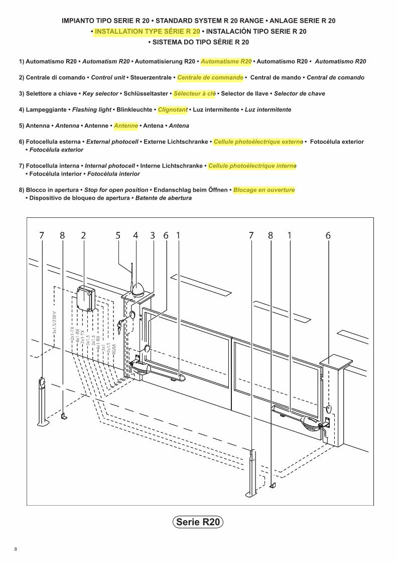
IMPIANTO TIPO SERIE R 20 • STANDARD SYSTEM R 20 RANGE • ANLAGE SERIE R 20 • INSTALLATION TYPE SÉRIE R 20 • INSTALACIÓN TIPO SERIE R 20
• SISTEMA DO TIPO SÉRIE R 20
1) Automatismo R20 • Automatism R20 • Automatisierung R20 • Automatisme R20 • Automatismo R20 • Automatismo R20
2) Centrale di comando • Control unit • Steuerzentrale • Centrale de commande • Central de mando • Central de comando
3) Selettore a chiave • Key selector • Schlüsseltaster • Sélecteur à clé • Selector de llave • Selector de chave
4) Lampeggiante • Flashing light • Blinkleuchte • Clignotant • Luz intermitente • Luz intermitente
5) Antenna • Antenna • Antenne • Antenne • Antena • Antena
6) Fotocellula esterna • External photocell • Externe Lichtschranke • Cellule photoélectrique externe • Fotocélula exterior • Fotocélula exterior
7) Fotocellula interna • Internal photocell • Interne Lichtschranke • Cellule photoélectrique interne • Fotocélula interior • Fotocélula interior
8) Blocco in apertura • Stop for open position • Endanschlag beim Öffnen • Blocage en ouverture • Dispositivo de bloqueo de apertura • Batente de abertura
9
Serie R20
R20 R20/300/301 R20/302/303 R20/500/501 R20/502/503
ALIMENTAZIONE • POWER SUPPLY • EINSPEISUNG • ALIMENTATION • ALIMENTACION • ALIMENTAÇÃO V 230 230 230 230
POTENZA NONIMALE • RATED POWER • NENNLEISTUNG • PUISSANCE NOMINALE • POTENCIA NOMINAL • POTÊNCIA NOMINAL W 200 215 200 215
CORRENTE • CURRENT • HÖCHSTGEWICHT • COURANT • CORRIENTE • CORRENTE A 1,1 1,2 1,1 1,2INTERMITTENZA • JOGGING • AUSSETZENDER BETRIEB • INTERMITTENCE • INTERMITENCIA • INTERMITÊNCIA % 40 40 40 40
TERMO PROTEZIONE MOTORE • MOTOR OVERLOAD CUTOUT • ÜBERHITZUNGSSCHUTZ MOTOR • THERMOPROTECTION MOTEUR • TERMOPROTECCION DEL MOTOR • PRO-TECÇÃO TÉRMICA DO MOTOR
°C 140 140 140 140
TEMPERATURA DI ESERCIZIO • WORKING TEMPERATURE• BETRIEBSTEMPERATUR • TEMPERATURE DE SERVICE • TEMPERATURA DE FUNCIONAMIENTO • TEMPERATURA DE FUNCIONAMENTO
°C -20 - +70 -20 - +70 -20 - +70 -20 - +70
GRADO DI PROTEZIONE • PROTECTION RATING • SCHUTZGRAD • DEGRE DE PROTEC-DEGRE DE PROTEC-TION • GRADO DE PROTECCION • GRAU DE PROTECÇÃO IP 43 43 43 43
PESO OPERATORE • OPERATOR WEIGHT • ANTRIEBSGEWICHT • POIDS OPERATEUR • PESO DEL OPERADOR • PESO DO OPERADOR kg 7.2 7.2 7.8 7.8
TEMPO APERTURA PER 90° • 90° OPENING TIME • ÖFFNUNGSZEIT FÜR 90° • TEMPS OUVER-90° OPENING TIME • ÖFFNUNGSZEIT FÜR 90° • TEMPS OUVER-ÖFFNUNGSZEIT FÜR 90° • TEMPS OUVER-TEMPS OUVER-TURE POUR 90° • TIEMPO PARA APERTURA DE 90° • TEMPO DE ABERTURA PARA 90° s 19" 28" 27" 42"
VELOCITA‘ • WORKING SPEED • GESCHWINDIGKEIT DER TORBEWEGUNG • VITESSE DE MANOEUVRE • VELOCIDAD DE MANIOBRA • VELOCIDADE DE MANOBRA cm/s 1.66 1.06 1.66 1.06
CONDENSATORE INSERITO • CAPACITOR CONNECTED • EINGESCHALTETER KONDEN-CAPACITOR CONNECTED • EINGESCHALTETER KONDEN-EINGESCHALTETER KONDEN-SATOR • CONDENSATEUR CONNECTE • CONDENSADOR CONECTADO • CONDENSADOR ACTIVADO
μf 16 8 16 8
SPINTA • TRUST • SCHUB • POUSSEE • EMPUJE • IMPULSO N 2500 2800 2500 2800CORSA • TRAVEL • HUB • COURSE • CARRERA • CURSO mm 320 320 520 520
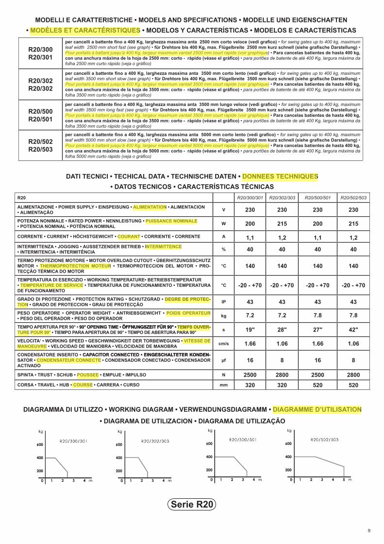
DATI TECNICI • TECHICAL DATA • TECHNISCHE DATEN • DONNEES TECHNIQUES • DATOS TECNICOS • CARACTERÍSTICAS TÉCNICAS
MODELLI E CARATTERISTICHE • MODELS AND SPECIFICATIONS • MODELLE UND EIGENSCHAFTEN • MODÈLES ET CARACTÉRISTIQUES • MODELOS Y CARACTERÍSTICAS • MODELOS E CARACTERÍSTICAS
R20/300R20/301
per cancelli a battente fino a 400 Kg, larghezza massima anta 2500 mm corto veloce (vedi grafico) • for swing gates up to 400 kg, maximum leaf width 2500 mm short fast (see graph) • für Drehtore bis 400 Kg, max. Flügelbreite 2500 mm kurz schnell (siehe grafische Darstellung) • Pour portails à battant jusqu’à 400 Kg, largeur maximum vantail 2500 mm court rapide (voir graphique) • Para cancelas batientes de hasta 400 kg, con una anchura máxima de la hoja de 2500 mm: corto - rápido (véase el gráfico) • para portões de batente de até 400 Kg, largura máxima da folha 2500 mm curto rápido (veja o gráfico)
R20/302R20/302
per cancelli a battente fino a 400 Kg, larghezza massima anta 3500 mm corto lento (vedi grafico) • for swing gates up to 400 kg, maximum leaf width 3500 mm short slow (see graph) • für Drehtore bis 400 Kg, max. Flügelbreite 3500 mm kurz schnell (siehe grafische Darstellung) • Pour portails à battant jusqu’à 400 Kg, largeur maximum vantail 3500 mm court rapide (voir graphique) • Para cancelas batientes de hasta 400 kg, con una anchura máxima de la hoja de 3500 mm: corto - rápido (véase el gráfico) • para portões de batente de até 400 Kg, largura máxima da folha 3500 mm curto rápido (veja o gráfico)
R20/500R20/501
per cancelli a battente fino a 400 Kg, larghezza massima anta 3500 mm lungo veloce (vedi grafico) • for swing gates up to 400 kg, maximum leaf width 3500 mm long fast (see graph) • für Drehtore bis 400 Kg, max. Flügelbreite 3500 mm kurz schnell (siehe grafische Darstellung) • Pour portails à battant jusqu’à 400 Kg, largeur maximum vantail 3500 mm court rapide (voir graphique) • Para cancelas batientes de hasta 400 kg, con una anchura máxima de la hoja de 3500 mm: corto - rápido (véase el gráfico) • para portões de batente de até 400 Kg, largura máxima da folha 3500 mm curto rápido (veja o gráfico)
R20/502R20/503
per cancelli a battente fino a 400 Kg, larghezza massima anta 5000 mm corto lento (vedi grafico) • for swing gates up to 400 kg, maximum leaf width 5000 mm short slow (see graph) • für Drehtore bis 400 Kg, max. Flügelbreite 5000 mm kurz schnell (siehe grafische Darstellung) • Pour portails à battant jusqu’à 400 Kg, largeur maximum vantail 5000 mm court rapide (voir graphique) • Para cancelas batientes de hasta 400 kg, con una anchura máxima de la hoja de 5000 mm: corto - rápido (véase el gráfico) • para portões de batente de até 400 Kg, largura máxima da folha 5000 mm curto rápido (veja o gráfico)
DIAGRAMMA DI UTILIZZO • WORKING DIAGRAM • VERWENDUNGSDIAGRAMM • DIAGRAMME D’UTILISATION
• DIAGRAMA DE UTILIZACION • DIAGRAMA DE UTILIZAÇÃO
10
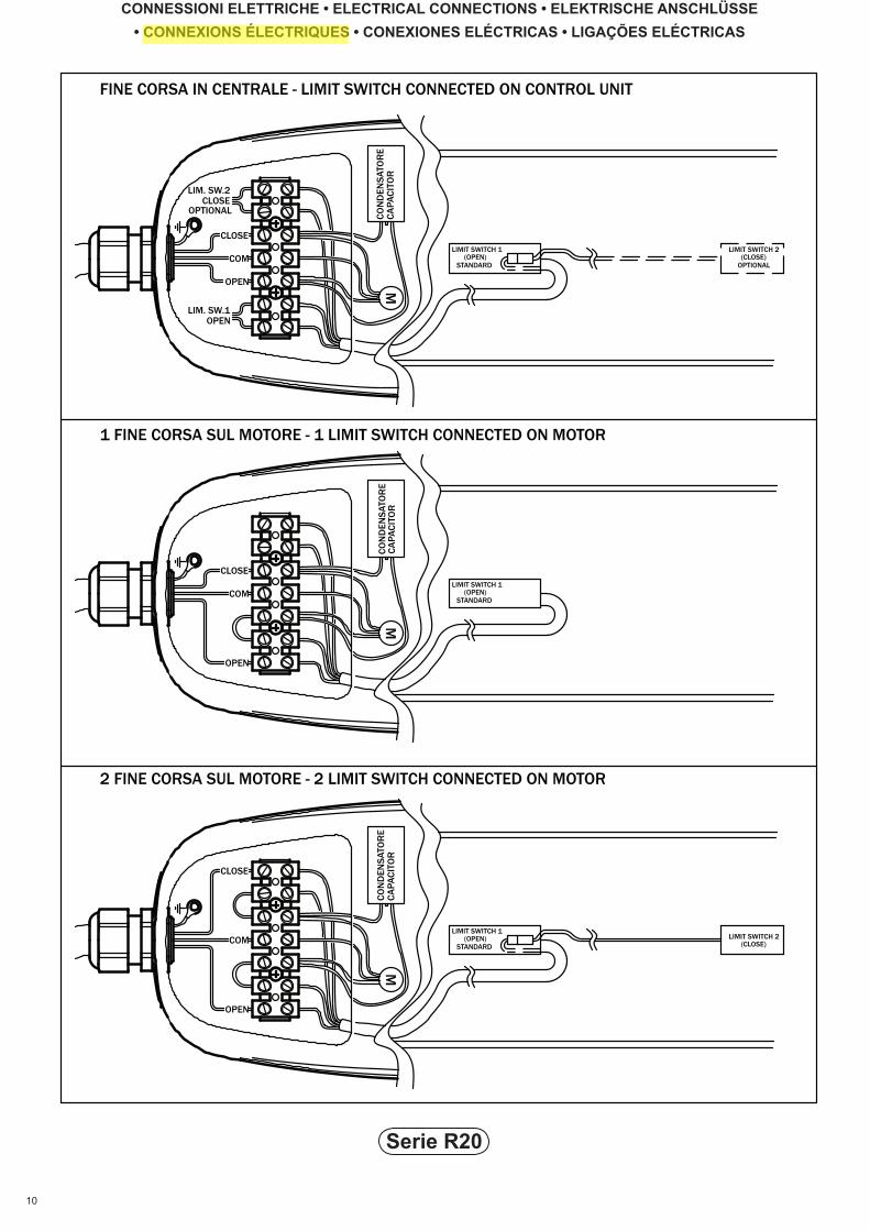
CONNESSIONI ELETTRICHE • ELECTRICAL CONNECTIONS • ELEKTRISCHE ANSCHLÜSSE • CONNEXIONS ÉLECTRIQUES • CONEXIONES ELÉCTRICAS • LIGAÇÕES ELÉCTRICAS
Serie R20
OPTIONAL
1 FINE CORSA SUL MOTORE - 1 LIMIT SWITCH CONNECTED ON MOTOR
2 FINE CORSA SUL MOTORE - 2 LIMIT SWITCH CONNECTED ON MOTOR
LIM. SW.1OPEN
CLOSELIM. SW.2
FINE CORSA IN CENTRALE - LIMIT SWITCH CONNECTED ON CONTROL UNIT
LIMIT SWITCH 2 (CLOSE)
(OPEN)COMSTANDARD
OPEN
M
LIMIT SWITCH 1
CLOSE
CLOSELIMIT SWITCH 1
(OPEN)STANDARD
OPEN
M
COM
LIMIT SWITCH 2 (CLOSE)OPTIONAL
CO
ND
ENS
ATO
RE
LIMIT SWITCH 1
STANDARD (OPEN)COM
OPEN M
CLOSE
CA
PAC
ITO
RC
ON
DEN
SAT
OR
EC
APA
CIT
OR
CO
ND
ENS
ATO
RE
CA
PAC
ITO
R
11
VERIFICHE PRELIMINARI PRIMA DI INSTALLARE Controllare che il cancello abbia i requisiti necessari per essere automatizzato: 1- La struttura del cancello sia solida ed appropriata 2- le cerniere siano in buono stato e ben ingrassate 3- Il movimento manuale sia fluido e regolare per tutta la sua corsa senza inceppamenti
4- Prevedere sempre un fermo meccanico di arresto in apertura e chiusura, ben fissato al suolo, dotato di elemento elastico (gomma) con il compito di attutire il colpo di arresto, in caso di avaria dei fine corsa elettrici
PRELIMINARY CHECKS PRIOR TO INSTALLATION Check that the gate has the necessary requirements to be automated 1- The gate structure must be solid and suitable 2- The hinges must be in good condition and well greased
3- Manual movement must be smooth and regular without sticking at any point4- Gate stops for the open and close positions must always be installed firmly fixed to the ground and fitted with a resilient element (rubber) to deaden the impact should the limit switches fail
VOR DER INSTALLATION DURCHZUFÜHRENDE KONTROLLEN
Sicherstellen, dass das Tor die erforderlichen Voraussetzungen für eine Automatisierung erfüllt: 1- Die Torstruktur ist robust und geeignet. 2- Die Scharniere müssen in gutem Zustand und gut gefettet sein. 3- Die manuelle Bewegung des Tors läuft den gesamten Fahrweg über ungehindert leicht und regelmäßig.
4- Immer einen mechanischen Endanschlag für Tor-Auf / Tor-Zu vorsehen, der fest am Untergrund angebracht ist.Dieser hat über ein elastisches Element (Gummi) zu verfügen, das die Aufgabe hat, den Aufprall abzudämpfen, sollten die elektrischen Endschalter defekt sein.
CONTRÔLES PRÉLIMINAIRES AVANT L’INSTALLATION S’assurer que le portail possède les caractéristiques requises pour être automatisé: 1- Structure du portail solide et appropriée 2- Charnières en bon état et bien graissées 3- Mouvement manuel fluide et régulier sur toute la course sans à-coups
4- Prévoir toujours un dispositif mécanique d’arrêt en ouverture et fermeture, bien fixé au sol, doté d’élément élastique (caoutchouc) ayant pour fonction d’amortir le coup d’arrêt en cas de dysfonctionnement des fins de course électriques
CONTROLES PREVIOS ANTES DE LA INSTALACIÓN Controle que la cancela tenga los requisitos necesarios para ser automatizada: 1- La estructura de la cancela sea sólida y apropiada. 2- Los goznes estén en buen estado y bien engrasados. 3- El movimiento manual sea fluido y correcto por toda su carrera, sin obstrucciones. 4- Predisponga siempre un tope mecánico de apertura y cierre, bien fijado al suelo y dotado de elemento elástico (goma), con la función de amortiguar el choque en caso de avería de los fines de carrera eléctricos.
CONTROLOS PRELIMINARES ANTES DA INSTALAÇÃO Controle se o portão possui os requisitos necessários para ser automatizado: 1- a estrutura do portão deve ser sólida e apropriada; 2- se as dobradiças estão em bom estado e bem lubrificadas; 3- o movimento manual deve ser fluido e regular em todo o seu curso sem impedimentos; 4- instale sempre uma segurança mecânica de paragem na abertura e fecho, bem fixada no pavimento, com elemento elástico (borracha) cuja função é a de
amortecer a batida de paragem, em caso de avaria dos fins de curso eléctricos.
GB
I
D
F
P
E
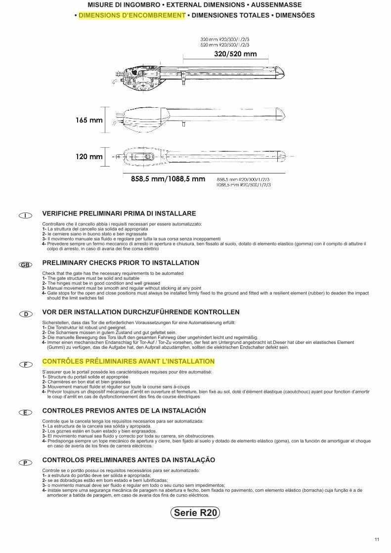
MISURE DI INGOMBRO • EXTERNAL DIMENSIONS • AUSSENMASSE • DIMENSIONS D’ENCOMBREMENT • DIMENSIONES TOTALES • DIMENSÕES
Serie R20
12
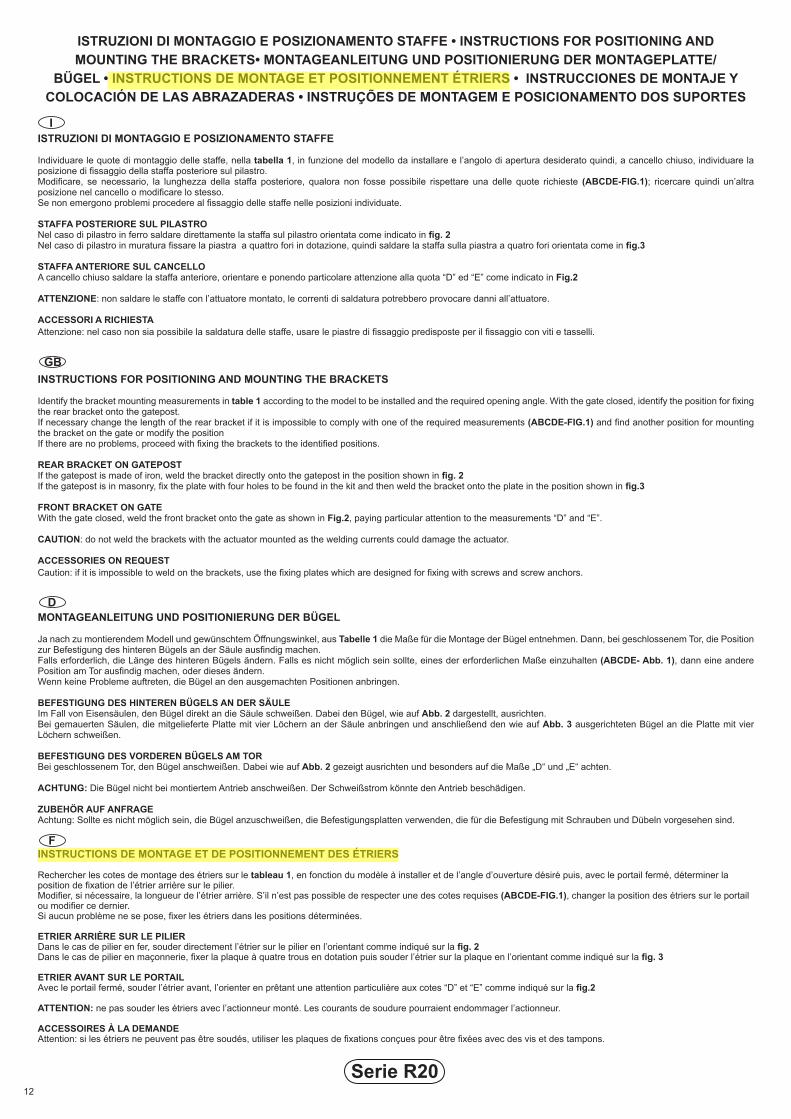
ISTRUZIONI DI MONTAGGIO E POSIZIONAMENTO STAFFE
Individuare le quote di montaggio delle staffe, nella tabella 1, in funzione del modello da installare e l’angolo di apertura desiderato quindi, a cancello chiuso, individuare la posizione di fissaggio della staffa posteriore sul pilastro.Modificare, se necessario, la lunghezza della staffa posteriore, qualora non fosse possibile rispettare una delle quote richieste (ABCDE-FIG.1); ricercare quindi un’altra posizione nel cancello o modificare lo stesso.Se non emergono problemi procedere al fissaggio delle staffe nelle posizioni individuate.
STAFFA POSTERIORE SUL PILASTRONel caso di pilastro in ferro saldare direttamente la staffa sul pilastro orientata come indicato in fig. 2Nel caso di pilastro in muratura fissare la piastra a quattro fori in dotazione, quindi saldare la staffa sulla piastra a quatro fori orientata come in fig.3
STAFFA ANTERIORE SUL CANCELLOA cancello chiuso saldare la staffa anteriore, orientare e ponendo particolare attenzione alla quota “D” ed “E” come indicato in Fig.2
ATTENZIONE: non saldare le staffe con l’attuatore montato, le correnti di saldatura potrebbero provocare danni all’attuatore.
ACCESSORI A RICHIESTAAttenzione: nel caso non sia possibile la saldatura delle staffe, usare le piastre di fissaggio predisposte per il fissaggio con viti e tasselli.
INSTRUCTIONS FOR POSITIONING AND MOUNTING THE BRACKETS
Identify the bracket mounting measurements in table 1 according to the model to be installed and the required opening angle. With the gate closed, identify the position for fixing the rear bracket onto the gatepost.If necessary change the length of the rear bracket if it is impossible to comply with one of the required measurements (ABCDE-FIG.1) and find another position for mounting the bracket on the gate or modify the positionIf there are no problems, proceed with fixing the brackets to the identified positions.
REAR BRACKET ON GATEPOSTIf the gatepost is made of iron, weld the bracket directly onto the gatepost in the position shown in fig. 2If the gatepost is in masonry, fix the plate with four holes to be found in the kit and then weld the bracket onto the plate in the position shown in fig.3
FRONT BRACKET ON GATEWith the gate closed, weld the front bracket onto the gate as shown in Fig.2, paying particular attention to the measurements “D” and “E”.
CAUTION: do not weld the brackets with the actuator mounted as the welding currents could damage the actuator.
ACCESSORIES ON REQUESTCaution: if it is impossible to weld on the brackets, use the fixing plates which are designed for fixing with screws and screw anchors.
MONTAGEANLEITUNG UND POSITIONIERUNG DER BÜGEL
Ja nach zu montierendem Modell und gewünschtem Öffnungswinkel, aus Tabelle 1 die Maße für die Montage der Bügel entnehmen. Dann, bei geschlossenem Tor, die Position zur Befestigung des hinteren Bügels an der Säule ausfindig machen. Falls erforderlich, die Länge des hinteren Bügels ändern. Falls es nicht möglich sein sollte, eines der erforderlichen Maße einzuhalten (ABCDE- Abb. 1), dann eine andere Position am Tor ausfindig machen, oder dieses ändern.Wenn keine Probleme auftreten, die Bügel an den ausgemachten Positionen anbringen.
BEFESTIGUNG DES HINTEREN BÜGELS AN DER SÄULEIm Fall von Eisensäulen, den Bügel direkt an die Säule schweißen. Dabei den Bügel, wie auf Abb. 2 dargestellt, ausrichten.Bei gemauerten Säulen, die mitgelieferte Platte mit vier Löchern an der Säule anbringen und anschließend den wie auf Abb. 3 ausgerichteten Bügel an die Platte mit vier Löchern schweißen.
BEFESTIGUNG DES VORDEREN BÜGELS AM TORBei geschlossenem Tor, den Bügel anschweißen. Dabei wie auf Abb. 2 gezeigt ausrichten und besonders auf die Maße „D“ und „E“ achten.
ACHTUNG: Die Bügel nicht bei montiertem Antrieb anschweißen. Der Schweißstrom könnte den Antrieb beschädigen.
ZUBEHÖR AUF ANFRAGEAchtung: Sollte es nicht möglich sein, die Bügel anzuschweißen, die Befestigungsplatten verwenden, die für die Befestigung mit Schrauben und Dübeln vorgesehen sind.
INSTRUCTIONS DE MONTAGE ET DE POSITIONNEMENT DES ÉTRIERS
Rechercher les cotes de montage des étriers sur le tableau 1, en fonction du modèle à installer et de l’angle d’ouverture désiré puis, avec le portail fermé, déterminer la position de fixation de l’étrier arrière sur le pilier.Modifier, si nécessaire, la longueur de l’étrier arrière. S’il n’est pas possible de respecter une des cotes requises (ABCDE-FIG.1), changer la position des étriers sur le portail ou modifier ce dernier.Si aucun problème ne se pose, fixer les étriers dans les positions déterminées.
ETRIER ARRIÈRE SUR LE PILIERDans le cas de pilier en fer, souder directement l’étrier sur le pilier en l’orientant comme indiqué sur la fig. 2Dans le cas de pilier en maçonnerie, fixer la plaque à quatre trous en dotation puis souder l’étrier sur la plaque en l’orientant comme indiqué sur la fig. 3
ETRIER AVANT SUR LE PORTAILAvec le portail fermé, souder l’étrier avant, l’orienter en prêtant une attention particulière aux cotes “D” et “E” comme indiqué sur la fig.2
ATTENTION: ne pas souder les étriers avec l’actionneur monté. Les courants de soudure pourraient endommager l’actionneur.
ACCESSOIRES À LA DEMANDEAttention: si les étriers ne peuvent pas être soudés, utiliser les plaques de fixations conçues pour être fixées avec des vis et des tampons.
Serie R20
ISTRUZIONI DI MONTAGGIO E POSIZIONAMENTO STAFFE • INSTRUCTIONS FOR POSITIONING AND MOUNTING THE BRACKETS• MONTAGEANLEITUNG UND POSITIONIERUNG DER MONTAGEPLATTE/
BÜGEL • INSTRUCTIONS DE MONTAGE ET POSITIONNEMENT ÉTRIERS • INSTRUCCIONES DE MONTAJE Y COLOCACIÓN DE LAS ABRAZADERAS • INSTRUÇÕES DE MONTAGEM E POSICIONAMENTO DOS SUPORTES
GB
I
D
F
13
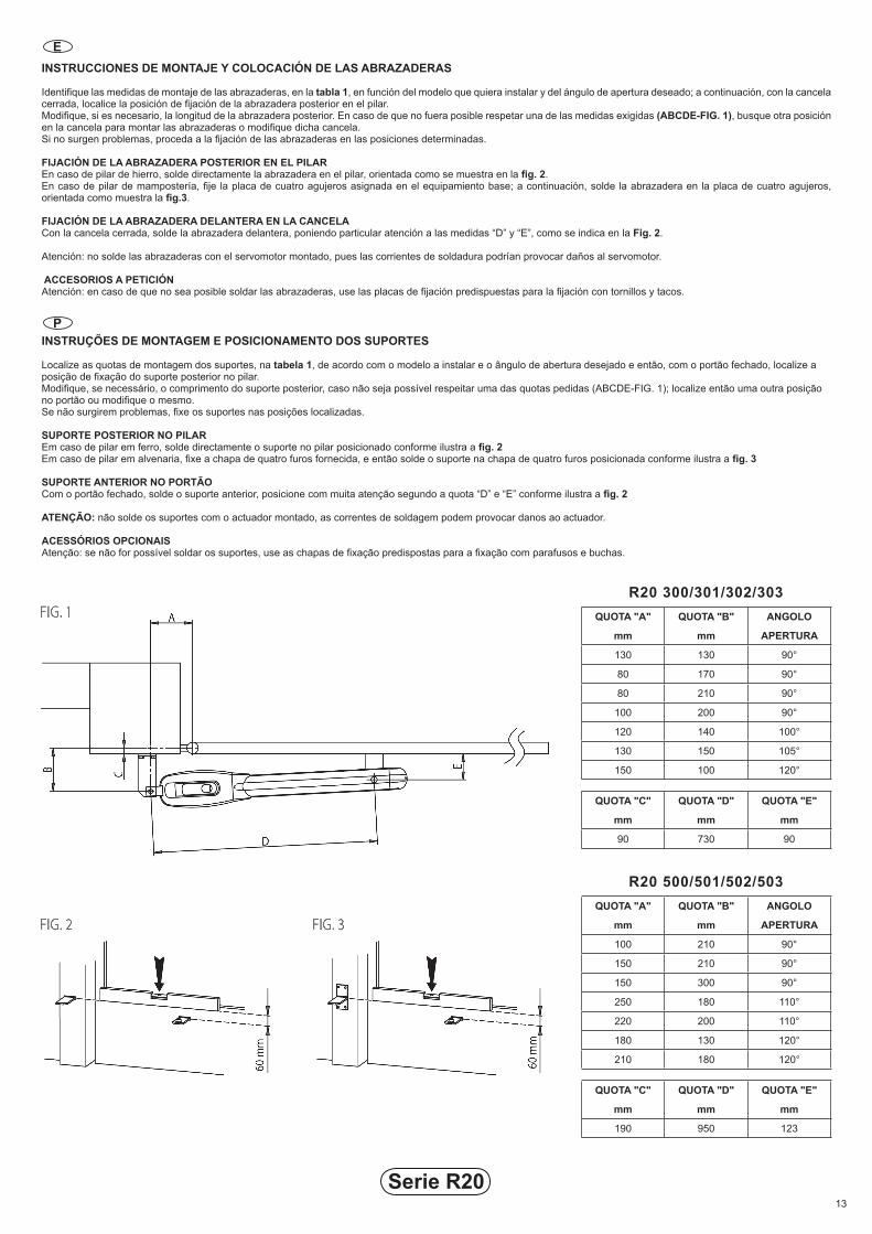
INSTRUCCIONES DE MONTAJE Y COLOCACIÓN DE LAS ABRAZADERAS
Identifique las medidas de montaje de las abrazaderas, en la tabla 1, en función del modelo que quiera instalar y del ángulo de apertura deseado; a continuación, con la cancela cerrada, localice la posición de fijación de la abrazadera posterior en el pilar.Modifique, si es necesario, la longitud de la abrazadera posterior. En caso de que no fuera posible respetar una de las medidas exigidas (ABCDE-FIG. 1), busque otra posición en la cancela para montar las abrazaderas o modifique dicha cancela.Si no surgen problemas, proceda a la fijación de las abrazaderas en las posiciones determinadas.
FIJACIÓN DE LA ABRAZADERA POSTERIOR EN EL PILAREn caso de pilar de hierro, solde directamente la abrazadera en el pilar, orientada como se muestra en la fig. 2.En caso de pilar de mampostería, fije la placa de cuatro agujeros asignada en el equipamiento base; a continuación, solde la abrazadera en la placa de cuatro agujeros, orientada como muestra la fig.3.
FIJACIÓN DE LA ABRAZADERA DELANTERA EN LA CANCELACon la cancela cerrada, solde la abrazadera delantera, poniendo particular atención a las medidas “D” y “E”, como se indica en la Fig. 2.
Atención: no solde las abrazaderas con el servomotor montado, pues las corrientes de soldadura podrían provocar daños al servomotor.
ACCESORIOS A PETICIÓNAtención: en caso de que no sea posible soldar las abrazaderas, use las placas de fijación predispuestas para la fijación con tornillos y tacos.
INSTRUÇÕES DE MONTAGEM E POSICIONAMENTO DOS SUPORTES
Localize as quotas de montagem dos suportes, na tabela 1, de acordo com o modelo a instalar e o ângulo de abertura desejado e então, com o portão fechado, localize a posição de fixação do suporte posterior no pilar.Modifique, se necessário, o comprimento do suporte posterior, caso não seja possível respeitar uma das quotas pedidas (ABCDE-FIG. 1); localize então uma outra posição no portão ou modifique o mesmo.Se não surgirem problemas, fixe os suportes nas posições localizadas.
SUPORTE POSTERIOR NO PILAREm caso de pilar em ferro, solde directamente o suporte no pilar posicionado conforme ilustra a fig. 2Em caso de pilar em alvenaria, fixe a chapa de quatro furos fornecida, e então solde o suporte na chapa de quatro furos posicionada conforme ilustra a fig. 3
SUPORTE ANTERIOR NO PORTÃOCom o portão fechado, solde o suporte anterior, posicione com muita atenção segundo a quota “D” e “E” conforme ilustra a fig. 2
ATENÇÃO: não solde os suportes com o actuador montado, as correntes de soldagem podem provocar danos ao actuador.
ACESSÓRIOS OPCIONAISAtenção: se não for possível soldar os suportes, use as chapas de fixação predispostas para a fixação com parafusos e buchas.
Serie R20
E
P
QUOTA "A"
mm
QUOTA "B"
mm
ANGOLO
APERTURA
130 130 90°
80 170 90°
80 210 90°
100 200 90°
120 140 100°
130 150 105°
150 100 120°
QUOTA "C"
mm
QUOTA "D"
mm
QUOTA "E"
mm
90 730 90
R20 300/301/302/303
QUOTA "A"
mm
QUOTA "B"
mm
ANGOLO
APERTURA
100 210 90°
150 210 90°
150 300 90°
250 180 110°
220 200 110°
180 130 120°
210 180 120°
QUOTA "C"
mm
QUOTA "D"
mm
QUOTA "E"
mm
190 950 123
R20 500/501/502/503
14
Serie R20
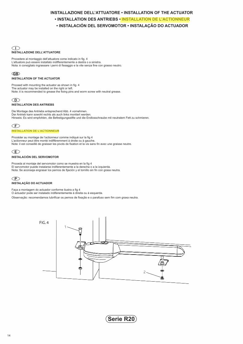
INSTALLAZIONE DELL’ATTUATORE
Procedere al montaggio dell’attuatore come indicato in fig. 4L’attuatore può essere installato indifferentemente a destra o a sinistra.Nota: è consigliato ingrassare i perni di fissaggio e la vite senza fine con grasso neutro.
INSTALLATION OF THE ACTUATOR
Proceed with mounting the actuator as shown in fig. 4The actuator may be installed on the right or left.Note: it is recommended to grease the fixing pins and worm screw with neutral grease.
INSTALLATION DES ANTRIEBS
Die Montage des Antriebs entsprechend Abb. 4 vornehmen.Der Antrieb kann sowohl rechts als auch links montiert werden.Hinweis: Es wird empfohlen, die Befestigungsstifte und die Endlosschraube mit neutralem Fett zu schmieren.
INSTALLATION DE L’ACTIONNEUR
Procéder au montage de l’actionneur comme indiqué sur la fig 4L’actionneur peut être monté indifféremment à droite ou à gauche.Note: il est conseillé de graisser les pivots de fixation et la vis sans fin avec une graisse neutre.
INSTALACIÓN DEL SERVOMOTOR
Proceda al montaje del servomotor como se muestra en la fig 4El servomotor puede instalarse indiferentemente a la derecha o a la izquierda.Nota: Se aconseja engrasar los pernos de fijación y el tornillo sin fin con grasa neutra.
INSTALAÇÃO DO ACTUADOR
Faça a montagem do actuador conforme ilustra a fig 4O actuador pode ser instalado indiferentemente à direita ou à esquerda.Observação: recomendamos lubrificar os pernos de fixação e o parafuso sem fim com graxa neutra.
INSTALLAZIONE DELL’ATTUATORE • INSTALLATION OF THE ACTUATOR • INSTALLATION DES ANTRIEBS • INSTALLATION DE L’ACTIONNEUR • INSTALACIÓN DEL SERVOMOTOR • INSTALAÇÃO DO ACTUADOR
GB
I
D
E
P
F
15
INSTALLAZIONE DELL’ATTUATORE
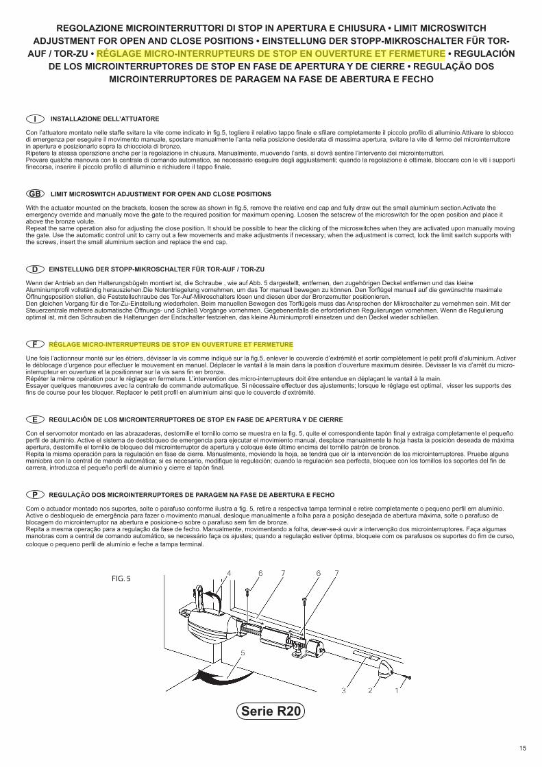
Con l’attuatore montato nelle staffe svitare la vite come indicato in fig.5, togliere il relativo tappo finale e sfilare completamente il piccolo profilo di alluminio.Attivare lo sblocco di emergenza per eseguire il movimento manuale, spostare manualmente l’anta nella posizione desiderata di massima apertura, svitare la vite di fermo del microinterruttore in apertura e posizionarlo sopra la chiocciola di bronzo.Ripetere la stessa operazione anche per la regolazione in chiusura. Manualmente, muovendo l’anta, si dovrà sentire l’intervento dei microinterruttori.Provare qualche manovra con la centrale di comando automatico, se necessario eseguire degli aggiustamenti; quando la regolazione è ottimale, bloccare con le viti i supporti finecorsa, inserire il piccolo profilo di alluminio e richiudere il tappo finale.
LIMIT MICROSWITCH ADJUSTMENT FOR OPEN AND CLOSE POSITIONS
With the actuator mounted on the brackets, loosen the screw as shown in fig.5, remove the relative end cap and fully draw out the small aluminium section.Activate the emergency override and manually move the gate to the required position for maximum opening. Loosen the setscrew of the microswitch for the open position and place it above the bronze volute.Repeat the same operation also for adjusting the close position. It should be possible to hear the clicking of the microswitches when they are activated upon manually moving the gate. Use the automatic control unit to carry out a few movements and make adjustments if necessary; when the adjustment is correct, lock the limit switch supports with the screws, insert the small aluminium section and replace the end cap.
EINSTELLUNG DER STOPP-MIKROSCHALTER FÜR TOR-AUF / TOR-ZU
Wenn der Antrieb an den Halterungsbügeln montiert ist, die Schraube , wie auf Abb. 5 dargestellt, entfernen, den zugehörigen Deckel entfernen und das kleine Aluminiumprofil vollständig herausziehen.Die Notentriegelung vornehmen, um das Tor manuell bewegen zu können. Den Torflügel manuell auf die gewünschte maximale Öffnungsposition stellen, die Feststellschraube des Tor-Auf-Mikroschalters lösen und diesen über der Bronzemutter positionieren.Den gleichen Vorgang für die Tor-Zu-Einstellung wiederholen. Beim manuellen Bewegen des Torflügels muss das Ansprechen der Mikroschalter zu vernehmen sein. Mit der Steuerzentrale mehrere automatische Öffnungs- und Schließ Vorgänge vornehmen. Gegebenenfalls die erforderlichen Regulierungen vornehmen. Wenn die Regulierung optimal ist, mit den Schrauben die Halterungen der Endschalter festziehen, das kleine Aluminiumprofil einsetzen und den Deckel wieder schließen.
RÉGLAGE MICRO-INTERRUPTEURS DE STOP EN OUVERTURE ET FERMETURE
Une fois l’actionneur monté sur les étriers, dévisser la vis comme indiqué sur la fig.5, enlever le couvercle d’extrémité et sortir complètement le petit profil d’aluminium. Activer le déblocage d’urgence pour effectuer le mouvement en manuel. Déplacer le vantail à la main dans la position d’ouverture maximum désirée. Dévisser la vis d’arrêt du micro-interrupteur en ouverture et la positionner sur la vis sans fin en bronze.Répéter la même opération pour le réglage en fermeture. L’intervention des micro-interrupteurs doit être entendue en déplaçant le vantail à la main.Essayer quelques manœuvres avec la centrale de commande automatique. Si nécessaire effectuer des ajustements; lorsque le réglage est optimal, visser les supports des fins de course pour les bloquer. Replacer le petit profil en aluminium ainsi que le couvercle d’extrémité.
REGULACIÓN DE LOS MICROINTERRUPTORES DE STOP EN FASE DE APERTURA Y DE CIERRE
Con el servomotor montado en las abrazaderas, destornille el tornillo como se muestra en la fig. 5, quite el correspondiente tapón final y extraiga completamente el pequeño perfil de aluminio. Active el sistema de desbloqueo de emergencia para ejecutar el movimiento manual, desplace manualmente la hoja hasta la posición deseada de máxima apertura, destornille el tornillo de bloqueo del microinterruptor de apertura y coloque éste último encima del tornillo patrón de bronce.Repita la misma operación para la regulación en fase de cierre. Manualmente, moviendo la hoja, se tendrá que oír la intervención de los microinterruptores. Pruebe alguna maniobra con la central de mando automática; si es necesario, modifique la regulación; cuando la regulación sea perfecta, bloquee con los tornillos los soportes del fin de carrera, introduzca el pequeño perfil de aluminio y cierre el tapón final.
REGULAÇÃO DOS MICROINTERRUPTORES DE PARAGEM NA FASE DE ABERTURA E FECHO
Com o actuador montado nos suportes, solte o parafuso conforme ilustra a fig. 5, retire a respectiva tampa terminal e retire completamente o pequeno perfil em alumínio. Active o desbloqueio de emergência para fazer o movimento manual, desloque manualmente a folha para a posição desejada de abertura máxima, solte o parafuso de blocagem do microinterruptor na abertura e posicione-o sobre o parafuso sem fim de bronze.Repita a mesma operação para a regulação da fase de fecho. Manualmente, movimentando a folha, dever-se-á ouvir a intervenção dos microinterruptores. Faça algumas manobras com a central de comando automático, se necessário faça os ajustes; quando a regulação estiver óptima, bloqueie com os parafusos os suportes do fim de curso, coloque o pequeno perfil de alumínio e feche a tampa terminal.
GB
I
D
E
P
F
Serie R20
REGOLAZIONE MICROINTERRUTTORI DI STOP IN APERTURA E CHIUSURA • LIMIT MICROSWITCH ADJUSTMENT FOR OPEN AND CLOSE POSITIONS • EINSTELLUNG DER STOPP-MIKROSCHALTER FÜR TOR-
AUF / TOR-ZU • RÉGLAGE MICRO-INTERRUPTEURS DE STOP EN OUVERTURE ET FERMETURE • REGULACIÓN DE LOS MICROINTERRUPTORES DE STOP EN FASE DE APERTURA Y DE CIERRE • REGULAÇÃO DOS
MICROINTERRUPTORES DE PARAGEM NA FASE DE ABERTURA E FECHO
Serie R20 ROGER TECHNOLOGY
Via S. Botticelli 8 • 31021 Bonisiolo di Mogliano Veneto (Tv) • ItalyTel. +39 041.5937023 • Fax. +39 041.5937024
[email protected] • www.rogertechnology.com
KONFORMITÄTSERKLÄRUNGDer Unterzeichnende, Vertreter folgenden HerstellersRoger TechnologyVia Botticelli 831020 Bonisiolo di Mogliano V.to (TV)ERKLÄRT, dass das nachfolgend beschriebene Gerät:Beschreibung: Automatisierung für DrehtoreModell: R20mit den gesetzlichen Bestimmungen übereinstimmt, die folgende Richtlinien umsetzen
•Richtlinie 89/336/EWG (EMV-Richtlinie) und darauf folgende Abänderungen•Richtlinie 73/23/EWG (Niederspannungsrichtlinie) und darauf folgende Abänderungen
und dass alle im Folgenden aufgeführten Normen und/oder technischen Spezifikationen eingehalten wurdenEN 61000-6-3EN 61000-6-2EN 60335-1EN 60335-2-103Die letzten beiden Ziffern des Jahres, in dem die 03-Kennzeichnung angebracht wurdeOrt: Mogliano V.toDatum: 02-01-2003
Unterschrift:
DECLARAÇÃO DE CONFORMIDADEO abaixo assinado, representante do seguinte fabricanteRoger TechnologyVia Botticelli 831020 Bonisiolo di Mogliano V.to (TV)DECLARA que o aparelho aqui descrito:Descrição: Automações para portões de batenteModelo: R20Está em conformidade com as disposições legislativas que transpõem as seguintes directivas
• Directiva 89/336/CEE (Directiva EMC) e subsequentes emendas• Directiva 73/23/CEE (Directiva de Baixa Tensão) e subsequentes emendas
E que foram aplicadas todas as normas e/ou especificações técnicas indicadas a seguirEN 61000-6-3EN 61000-6-2EN 60335-1EN 60335-2-103Últimas duas cifras do ano em que foi aposta a marcação 03 Lugar: Mogliano V.toData: 02-01-2003
Assinatura:
DECLARACION DE CONFORMIDADEl que suscribe, en representación del siguiente constructor Roger TechnologyVia Botticelli, 831020 Bonisiolo di Mogliano V.to (TV)DECLARA que el equipo descrito a continuación:Descripción: Automatismos para cancelas batientesModelo: R20Es conforme a las disposiciones legislativas que transcriben las siguientes directivas:
•Directiva 89/336/CEE (Directiva EMC) y sucesivas modificaciones•Directiva 73/23/CEE (Directiva sobre Baja Tensión) y sucesivas modificaciones
y que han sido aplicadas todas las normas y/o especificaciones técnicas indicadas a continuación: EN 61000-6-3EN 61000-6-2EN 60335-1EN 60335-2-103Últimas dos cifras del año en que se ha fijado la marca 03 Lugar: Mogliano V.toFecha: 02-01-2003
Firma:
I GB
D
E P
F
DICHIARAZIONE DI CONFORMITA’Il sottoscritto, rappresentante il seguente costruttoreRoger TechnologyVia Botticelli 831020 Bonisiolo di Mogliano V.to (TV)DICHIARA che l’apparecchiatura descritta in appresso:Descrizione: Automazioni per cancelli a battenteModello: R20È conforme alle disposizioni legislative che traspongono le seguenti direttive:
•Direttiva 89/336/CEE (Direttiva EMC) e successivi emendamenti•Direttiva 73/23/CEE (Direttiva Bassa Tensione) e successivi emendamenti
E che sono state applicate tutte le norme e/o specifiche tecniche di seguito indicate EN 61000-6-3EN 61000-6-2EN 60335-1EN 60335-2-103Ultime due cifre dell’anno in cui è affissa la marcatura 03 Luogo: Mogliano V.to Data: 02-01-2003
Firma:
DECLARATION DE CONFORMITELe soussigné, représentant du constructeur suivantRoger TechnologyVia Botticelli 831020 Bonisiolo di Mogliano V.to (TV)DECLARE que l’équipement décrit ci-dessous:Description: Automatisme pour portails à battantModèle: R20Est conforme aux dispositions législatives qui répondent aux directives suivantes
•Directive 89/336/CEE (Directive EMC) et amendements successifs•Directive 73/23/CEE (Directive Basse Tension) et amendements successifs
Et que toutes les normes et/ou prescriptions techniques indiquées ci-dessous ont été appliquées EN 61000-6-3EN 61000-6-2EN 60335-1EN 60335-2-103Deux derniers chiffres de l’année où le marquage 03 a été affichéLieu: Mogliano V.toDate: 02-01-2003
Signature:
DECLARATION OF CONFORMITYThe undersigned, representing the following manufacturerRoger TechnologyVia Botticelli 831020 Bonisiolo di Mogliano V.to (TV)DECLARES that the equipment described below:Description: Swing gates automationModel: R20Is in conformity with the legislative provisions that transpose the following directives:
•Directive 89/336/EEC (EMC Directive) and subsequent amendments•Directive 73/23/EEC (Low Voltage Directive) and subsequent amendments
And has been designed and manufactured to all the following standards or technical specificationsEN 61000-6-3EN 61000-6-2EN 60335-1EN 60335-2-103Last two figures of the year in which the 03 mark was affixed Place: Mogliano V.toDate: 02-01-2003
Signature:
ROGER TECHNOLOGYVia S. Botticelli 8 • 31021 Bonisiolo di Mogliano Veneto (Tv) • Italy
Tel. +39 041.5937023 • Fax. +39 [email protected] • www.rogertechnology.com