Embed Size (px)
Citation preview
Advantages of Industrial Ethernet-
Comparisonof
Modbus over TCP/IPand
PROFINET
BachelorarbeitWintersemester 2010/2011
Johannes Kasberger0616782
Betreuung
Ao. Univ. Prof. Dr. Wolfgang Kastner
Erklärung
Hiermit erkläre ich, dass ich diese Arbeit selbständig verfasst habe, dass
ich die verwendeten Quellen und Hilfsmittel vollständig angegeben habe
und dass ich die Stellen der Arbeit – einschließlich Tabellen, Karten und
Abbildungen –, die anderen Werken oder dem Internet im Wortlaut oder
dem Sinn nach entnommen sind, auf jeden Fall unter Angabe der Quelle
als Entlehnung kenntlich gemacht habe.
Hereby I declare that this work has been written autonomously, that all
used sources and utilities are denoted accordingly and that these points
of the work - including tables, maps and figures - which where taken from
other creations or the Internet have been marked as borrowing by quoting
the original sources.
i
Contents
Erklärung i
Contents ii
List of Tables iii
List of Figures iii
Abstract iv
1 Industrial Communication 1
1.1 Automation Pyramid . . . . . . . . . . . . . . . . . . . . . . 1
1.2 Fieldbuses . . . . . . . . . . . . . . . . . . . . . . . . . . . . 2
1.3 Industrial Ethernet . . . . . . . . . . . . . . . . . . . . . . . 3
1.3.1 Ethernet . . . . . . . . . . . . . . . . . . . . . . . . . 4
1.3.2 Other layers . . . . . . . . . . . . . . . . . . . . . . . 5
1.3.3 Solutions . . . . . . . . . . . . . . . . . . . . . . . . 5
1.3.4 Beginning of Ethernet Wars? . . . . . . . . . . . . . 6
2 Modbus over TCP/IP 8
2.1 Basic Idea . . . . . . . . . . . . . . . . . . . . . . . . . . . . 8
2.1.1 Example communication . . . . . . . . . . . . . . . 11
2.2 Problems of Modbus over TCP/IP . . . . . . . . . . . . . . 12
3 PROFINET 14
3.1 PROFINET CBA . . . . . . . . . . . . . . . . . . . . . . . . 14
3.2 PROFINET IO . . . . . . . . . . . . . . . . . . . . . . . . . 16
3.2.1 Cyclic Communication . . . . . . . . . . . . . . . . . 16
3.2.2 Acyclic Communication . . . . . . . . . . . . . . . . 19
3.2.3 Addressing . . . . . . . . . . . . . . . . . . . . . . . 19
3.2.4 Network Topology . . . . . . . . . . . . . . . . . . . 20
3.2.5 Web Integration . . . . . . . . . . . . . . . . . . . . 20
3.2.6 Security . . . . . . . . . . . . . . . . . . . . . . . . . 20
ii
3.2.7 Fieldbus Integration . . . . . . . . . . . . . . . . . . 21
4 Conclusion 22
Bibliography 26
List of Tables
1.1 Popular fieldbuses . . . . . . . . . . . . . . . . . . . . . . . . . 3
1.2 Popular Industrial Ethernet solutions . . . . . . . . . . . . . . 7
2.1 Modbus Request . . . . . . . . . . . . . . . . . . . . . . . . . . 11
2.2 Modbus Response . . . . . . . . . . . . . . . . . . . . . . . . . 12
4.1 Comparison of Modbus over TCP/IP and PROFINET . . . . . 25
List of Figures
1.1 Automation Pyramid [12, p. 536] . . . . . . . . . . . . . . . . . 1
2.1 General Modbus frame [9, p. 4] . . . . . . . . . . . . . . . . . 9
2.2 Modbus over TCP/IP frame [10, p. 4] . . . . . . . . . . . . . . 9
2.3 Error Free Modbus Transaction [9, p. 4] . . . . . . . . . . . . 11
3.1 PROFINET CBA stack variants [13, p. 35] . . . . . . . . . . . 16
3.2 PROFINET timing [5, p. 1128] . . . . . . . . . . . . . . . . . . 17
iii
Abstract
The topic of this work is Industrial Ethernet and why it is developed and
used. In the recent years fieldbuses have been used to connect devices
on the factory floor. Now it seems that the next step in development is
taking place. The classic fieldbus protocols can’t satisfy today’s require-
ments and so modern protocols are stepping in. A promising approach is
to build solutions using Ethernet as base. This work tries to summarise
why fieldbuses are so successful and what steps have to be taken to use
Ethernet as a replacement.
After the introduction two representatives of this protocol class are
compared. The two protocols are Modbus over TCP/IP and PROFINET.
Modbus over TCP/IP is an extension of the popular Modbus protocol to
replace the serial connection with TCP/IP. PROFINET is the successor of
PROFIBUS and can be split up into PROFINET CBA and PROFINET IO.
iv
1 Industrial Communication
1.1 Automation Pyramid
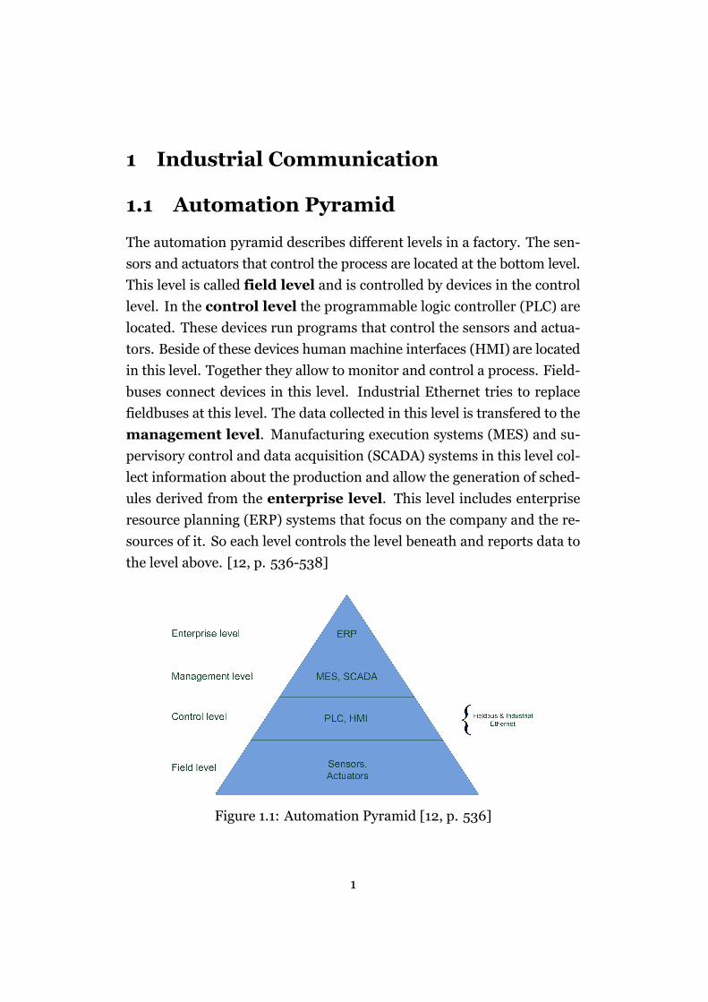
The automation pyramid describes different levels in a factory. The sen-
sors and actuators that control the process are located at the bottom level.
This level is called field level and is controlled by devices in the control
level. In the control level the programmable logic controller (PLC) are
located. These devices run programs that control the sensors and actua-
tors. Beside of these devices human machine interfaces (HMI) are located
in this level. Together they allow to monitor and control a process. Field-
buses connect devices in this level. Industrial Ethernet tries to replace
fieldbuses at this level. The data collected in this level is transfered to the
management level. Manufacturing execution systems (MES) and su-
pervisory control and data acquisition (SCADA) systems in this level col-
lect information about the production and allow the generation of sched-
ules derived from the enterprise level. This level includes enterprise
resource planning (ERP) systems that focus on the company and the re-
sources of it. So each level controls the level beneath and reports data to
the level above. [12, p. 536-538]
Figure 1.1: Automation Pyramid [12, p. 536]
1
CHAPTER 1. INDUSTRIAL COMMUNICATION 2
1.2 Fieldbuses
This section is based on [16] and [6]. The development of fieldbuses started
around 1981. The goal was “to solve some end-user problems, coming
from the heterogeneity of their devices” [16, p. 82]. Many companies
started developing their own protocols. Their approaches were different
at a very basic level.
“PROFIBUS was based on a distributed control idea and in its orig-
inal form supported an object-oriented vertical communication accord-
ing to the client-server model in the spirit of the MAP/MMS specification.
FIP, on the other hand, was designed with a central, but strictly real-
time capable control scheme and with the newly developed producer-
consumer (producer-distributor-consumer) model for horizontal com-
munication” [6, p. 73].
Thomesse also agrees on that two different points of view what kind
of problem a fieldbus should solve: “a fieldbus is only a network for sim-
plifying the wiring between devices, or a fieldbus is the spinal column of
a distributed realtime system” [16, p. 81].
A list of common end-user requirements for fieldbuses as described in
[16, p. 83] is:
• safety, availability and, more generally, dependability
• better maintainability
• better modularity and capacity for evolution
• openness, interoperability, interchangeability, long lifetimes
• better performances and low cost
• end-user will not need to see the fieldbus
• lower costs
Although the end-user requirements are equal for all fieldbuses at least
50 different fieldbus protocols were developed. France (FIP) and Ger-
many (PROFIBUS) developed their own national standard and wanted
CHAPTER 1. INDUSTRIAL COMMUNICATION 3
them to become an international standard. This situation led to a situa-
tion called the “fieldbus wars”. It was impossible to agree on an interna-
tional fieldbus standard for nearly 15 years. The situation was solved in
1999 and resulted in IEC 61158. This standard includes all popular field-
buses. This standard stopped the fieldbus wars.
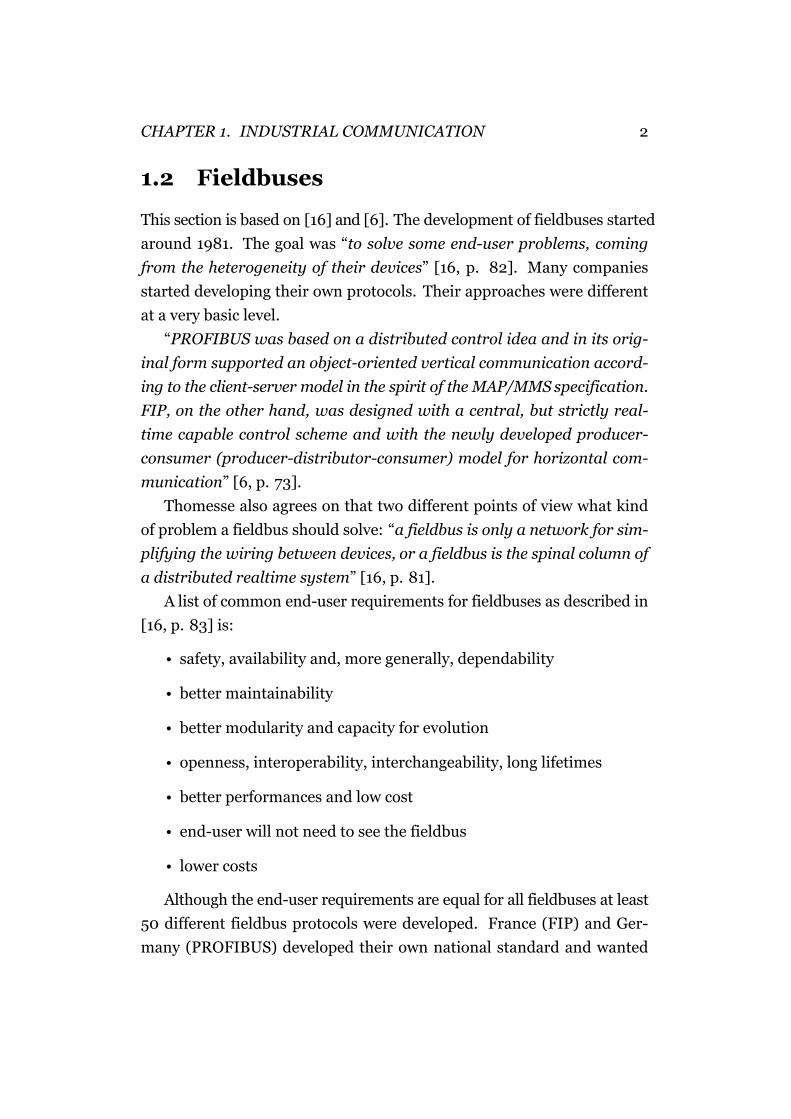
To give a few examples, a list of popular fieldbuses according to [3, p.
1102] is noted below:
WorldFIP PROFIBUSP Net Interbus
AS-Interface SERCOSLonWorks MVB
MIL-STD 1553 DeviceNetSDS CAN
Table 1.1: Popular fieldbuses
1.3 Industrial Ethernet
Nearly 25 years have passed since the development of the fieldbus proto-
cols, and the requirements have changed. Today, it is normal to connect
all kinds of things to the Internet.
“The only barrier to access devices in the field of the automation world,
from the Internet over a network connection, are the fieldbuses. There-
fore, the question is: why is it not possible to use Ethernet also in au-
tomation technology?” [5, p. 1118]
The requirements of the data transmission also changed. It is common
to transmit more data than before. The throughput that fieldbuses offer
is nevertheless very limited when compared to Ethernet or ATM [3].
In the office world, Ethernet and TCP/IP based networks are getting
cheaper and cheaper and at the same time faster (10 GB/s soon). This is
possible because Ethernet and TCP are used everywhere. All these facts
have encouraged vendors to develop Ethernet based solutions suitable for
usage in industrial environments [3, 5].
CHAPTER 1. INDUSTRIAL COMMUNICATION 4
Using the normal Ethernet as fieldbus replacement is impossible as it
is not a real-time network. As listed in [5] it doesn’t support:
• time-deterministic communication
• time-synchronized actions between field devices like drives
• efficient and frequent exchange of very small data records
According to [5, p. 1121], the user requirements for performance can
be divided into three classes:
• low-speed class for human control, delivery times around 100 ms,
which can be fulfilled with a standard TCP/IP system
• second class for process control, delivery times around 10 ms, pow-
erful equipment to handle TCP/IP in real-time or simplified proto-
col stack on normal equipment
• third class for motion control, delivery times around 1 ms, jitter not
more that 1µs, only reachable with modified hardware and modified
MAC (Medium Access Control)
1.3.1 Ethernet
Ethernet and the IEEE standard 802.3 have little difference and compat-
ibility was guaranteed. To share one medium between more devices, a
MAC algorithm named Carrier-Sense Multiple Access With Collision De-
tection (CSMA/CD) is used in both. This algorithm is the reason for the
indeterministic behavior of data transmission. When a station wants to
send data it waits until the medium is free for a time span called the inter-
frame gap. After that time interval of no traffic the station starts sending.
When more than one station starts sending a collision arises. This is de-
tected by the stations. To notify all stations of this collision, a jamming
signal is sent. Now the station chooses a random time to wait before trying
to send again. With each collision this time is doubled. Each station with
CHAPTER 1. INDUSTRIAL COMMUNICATION 5
data to send waits this randomly chosen time and starts sending again.
This procedure is repeated until the data is sent. [3, p. 1105]
Because of this behavior no upper bound for the transmission time can
be given. Under heavy load conditions it is possible that the MAC results
in unfair results.
“The Ethernet Capture Effect is the behavior wherein under high load,
one station is able to hold on to the channel to transmit packets consec-
utively, in spite of other station(s) contending for access. This is partic-
ularly acute in the case of a 2-node network, with one station receiving
an unfair share of the channel bandwidth over a transient period.” [14,
p. 228]
1.3.2 Other layers
“The behavior of the application is under the control of the end user,
i.e. the APs [Application Processes, J.K.] implemented on the distributed
sites and not under control of a protocol at a given layer. That means
that time constraints are given by the user.” [15, p. 372]
According to this it is impossible to establish real-time communica-
tion on a single layer. For the transport layer several real-time dedicated
protocols where proposed. But the most common are still TCP and UDP.
They are used in combination with the Internet Protocol (IP) as network
layer. The behavior of the routers that work on that layer have direct
impact on the real-time guarantees that can be given. Without special
routing policies an earlier received low priority message can delay a high
priority message. [3, p. 1103]
1.3.3 Solutions
To avoid the random behavior of the normal Ethernet MAC algorithm,
several different solutions have been developed. Some can be used in a
network of standard Ethernet devices others are not useable in such a sce-
nario. From this point of view, real-time Ethernet can be divided in two
CHAPTER 1. INDUSTRIAL COMMUNICATION 6
categories “Modifications That Alter Compatibility” [3] and “Modifica-
tions That Keep Compatibility” [3].
In [5, p. 1121] the different approaches are described as
• on top of TCP/IP: TCP/IP stack remains unchanged, real-time pro-
tocol defined in top layer
• on top of Ethernet: Standard Ethernet is used but TCP/UDP/IP pro-
tocols are replaced by own protocols
• Modified Ethernet: Ethernet protocol is modified
1.3.3.1 Modifications That Alter Compatibility
This category alters the MAC algorithm. Thus, these nodes can’t commu-
nicate with standard devices. The big advantage of low priced hardware
would be worthless if this approach requires totally new hardware. But
it is possible to create new solutions on base of IEEE 802.3 compliant
hardware.
1.3.3.2 Modifications That Keep Compatibility
Nodes that implement such solutions can coexist with standard Ether-
net devices in the same network and communicate with each other. It
is possible to distinguish two more classes. The homogeneous subclass
only guarantees to fulfill the requirements when all devices implement the
same features. The second subclass the heterogeneous gives guarantees
to fulfill the requirements even in presence of nodes with other Ethernet
modifications. [3, p. 1109]
1.3.4 Beginning of Ethernet Wars?
The question is if the industry and the IEC have learned from their past
failures. The fieldbus wars led to a complicated situation and didn’t make
the situation better for customers of fieldbuses. Although industrial Eth-
ernet is a recent approach many different solutions and products exist -
CHAPTER 1. INDUSTRIAL COMMUNICATION 7
all with different approaches and techniques. The question is if this will
lead to a similar deadlock situation as during the fieldbus wars?
The opinion in [7, p. 419] is that history won’t repeat itself. The au-
thors think that the IEC can’t afford a new standardization war which
would result in image loss. The vendors have also learned that block-
ing the standardization for a long time just results in compromises and
is very expensive. Furthermore, the IEC workgroups don’t search for one
standard but search for a multipart solution. As a result, it is expected
that the standardization process will go by smoothly.
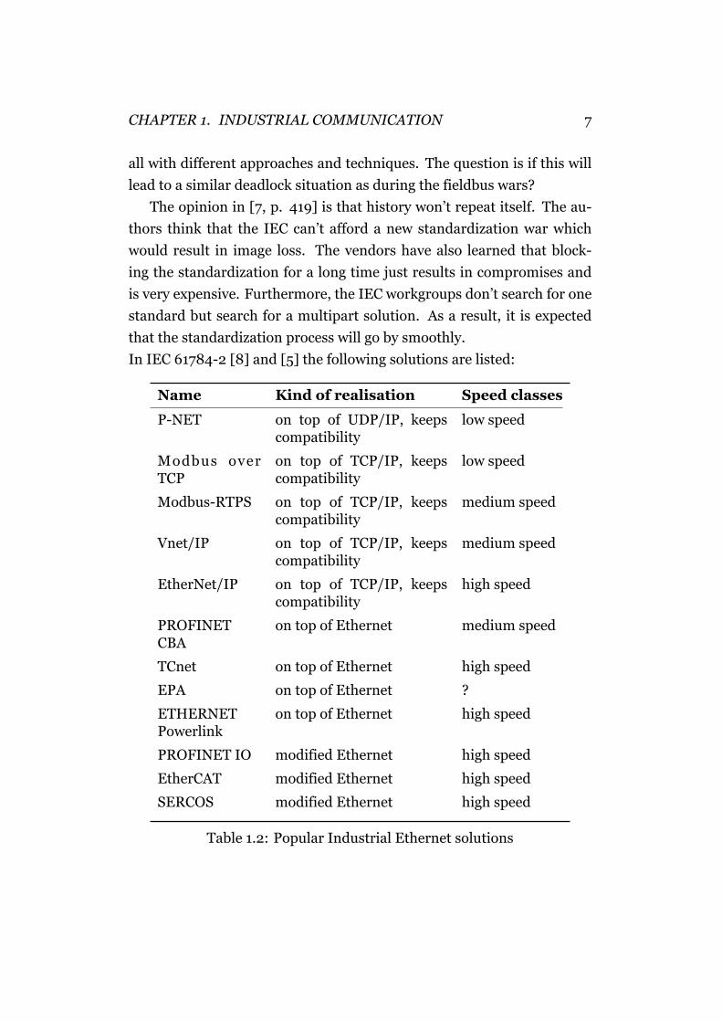
In IEC 61784-2 [8] and [5] the following solutions are listed:
Name Kind of realisation Speed classes
P-NET on top of UDP/IP, keepscompatibility
low speed
Modbus overTCP
on top of TCP/IP, keepscompatibility
low speed
Modbus-RTPS on top of TCP/IP, keepscompatibility
medium speed
Vnet/IP on top of TCP/IP, keepscompatibility
medium speed
EtherNet/IP on top of TCP/IP, keepscompatibility
high speed
PROFINETCBA
on top of Ethernet medium speed
TCnet on top of Ethernet high speed
EPA on top of Ethernet ?
ETHERNETPowerlink
on top of Ethernet high speed
PROFINET IO modified Ethernet high speed
EtherCAT modified Ethernet high speed
SERCOS modified Ethernet high speed
Table 1.2: Popular Industrial Ethernet solutions
2 Modbus over TCP/IP
The original Modbus protocol was developed by Modicon in 1979. This
protocol supports the communication between intelligent devices over a
serial line. Modbus is a very simple protocol and it is widely used in many
different parts of industry. In 1999, the protocol has been adopted to use
a TCP connection for the transport of the data. This variant is called Mod-
bus over TCP/IP. It keeps compatibility with other Ethernet products (see
Section 1.3.3).
In 2004, Schneider Electrics transferred the protocol to the Modbus
Organization1. This organization describes itself as a group of indepen-
dent users and suppliers of automation devices that want to push the
adoption of the Modbus protocol. They also share information about the
protocols and offer a certificate for devices and applications that apply to
the Modbus standard. The specification of the Modbus protocol can be
obtained free of charge2. The usage doesn’t require licensing fees.
2.1 Basic Idea
The following chapter is based on the Modbus Application Protocol Doc-
ument of the Modbus organization [9, p. 6].
Modbus is a pretty simple protocol but also powerful enough to sup-
port many types of applications. The basic idea is that a master requests
a value from a slave and the slave sends back the requested value.
The protocol defines two different data units. The simple protocol
data unit (PDU) is always the same and does not depend on the under-
lying communication layer. In the application data unit (ADU) frame ad-
ditional fields can be added (e.g. Modbus over TCP/IP adds the MBAP
Header).
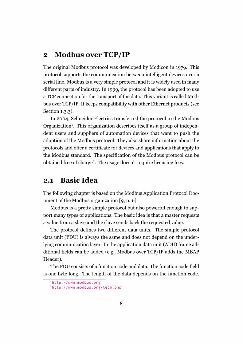
The PDU consists of a function code and data. The function code field
is one byte long. The length of the data depends on the function code.1http://www.modbus.org2http://www.modbus.org/tech.php
8
CHAPTER 2. MODBUS OVER TCP/IP 9
Figure 2.1: General Modbus frame [9, p. 4]
There are well defined public functions codes but it is also possible to de-
fine own function codes.
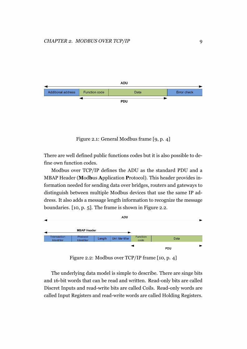
Modbus over TCP/IP defines the ADU as the standard PDU and a
MBAP Header (Modbus Application Protocol). This header provides in-
formation needed for sending data over bridges, routers and gateways to
distinguish between multiple Modbus devices that use the same IP ad-
dress. It also adds a message length information to recognize the message
boundaries. [10, p. 5]. The frame is shown in Figure 2.2.
Figure 2.2: Modbus over TCP/IP frame [10, p. 4]
The underlying data model is simple to describe. There are singe bits
and 16-bit words that can be read and written. Read-only bits are called
Discret Inputs and read-write bits are called Coils. Read-only words are
called Input Registers and read-write words are called Holding Registers.
CHAPTER 2. MODBUS OVER TCP/IP 10
These different regions are not necessary different memory regions but
can also overlap each other. It is possible to access the same memory bit
wise or word wise.
So each PDU contains a function code and an address the function
should apply to. Each data in a PDU is addressed from 0 to 65535. The
mapping of these addresses to actual data in the memory is totally vendor
specific.
The device that sends the request is called master but in terms of the
TCP communication it is a client. The device reacting to the request is
called slave with typical server functionality.
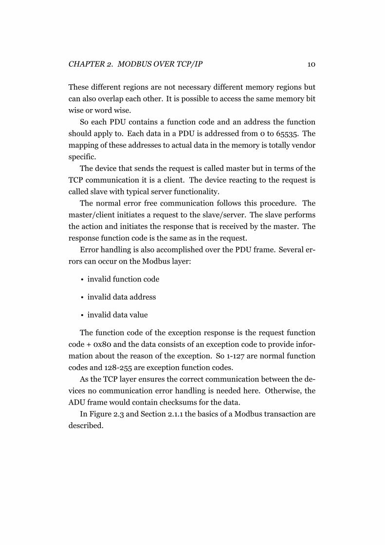
The normal error free communication follows this procedure. The
master/client initiates a request to the slave/server. The slave performs
the action and initiates the response that is received by the master. The
response function code is the same as in the request.
Error handling is also accomplished over the PDU frame. Several er-
rors can occur on the Modbus layer:
• invalid function code
• invalid data address
• invalid data value
The function code of the exception response is the request function
code + 0x80 and the data consists of an exception code to provide infor-
mation about the reason of the exception. So 1-127 are normal function
codes and 128-255 are exception function codes.
As the TCP layer ensures the correct communication between the de-
vices no communication error handling is needed here. Otherwise, the
ADU frame would contain checksums for the data.
In Figure 2.3 and Section 2.1.1 the basics of a Modbus transaction are
described.
CHAPTER 2. MODBUS OVER TCP/IP 11
Figure 2.3: Error Free Modbus Transaction [9, p. 4]
2.1.1 Example communication
Function code 0x04 (Read Input Registers) allows to read up to 125 regis-
ter values from another device [9, p. 16]. To use this function the starting
address and the byte count must be specified. The response includes the
function code 0x04 followed by the values of the requested registers. The
following example shows the usage of this function code. Other Modbus
functions work in a very similar way.
2.1.1.1 Request
A master wants to read four register values starting from the address 0x15.
In the PDU, registers are addressed starting at zero so the request must
be from address 0x14. (see Table 2.1)
Function code Starting Address Quantity of Input Register0x04 0x0014 2 ∗ 4
Table 2.1: Modbus Request
CHAPTER 2. MODBUS OVER TCP/IP 12
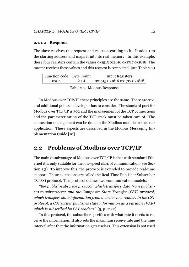
2.1.1.2 Response
The slave receives this request and reacts according to it. It adds 1 to
the starting address and maps it into its real memory. In this example,
these four registers contain the values 0x1515 0x1616 0x1717 0x1818. The
master receives these values and this request is completed. (see Table 2.2)
Function code Byte Count Input Registers0x04 2 ∗ 4 0x1515 0x1616 0x1717 0x1818
Table 2.2: Modbus Response
In Modbus over TCP/IP these principles are the same. There are sev-
eral additional points a developer has to consider. The standard port for
Modbus over TCP/IP is 502 and the management of the TCP connections
and the parameterization of the TCP stack must be taken care of. The
connection management can be done in the Modbus module or the user
application. These aspects are described in the Modbus Messaging Im-
plementation Guide [10].
2.2 Problems of Modbus over TCP/IP
The main disadvantage of Modbus over TCP/IP is that with standard Eth-
ernet it is only suitable for the low-speed class of communication (see Sec-
tion 1.3). To improve this, the protocol is extended to provide real-time
support. These extensions are called the Real-Time Publisher Subscriber
(RTPS) protocol. This protocol defines two communication models:
“the publish-subscribe protocol, which transfers data from publish-
ers to subscribers; and the Composite State Transfer (CST) protocol,
which transfers state information from a writer to a reader. In the CST
protocol, a CST writer publishes state information as a variable (VAR)
which is subscribed by CST readers.” [5, p. 1122]
In this protocol, the subscriber specifies with what rate it needs to re-
ceive the information. It also sets the maximum receive rate and the time
interval after that the information gets useless. This extension is not used
CHAPTER 2. MODBUS OVER TCP/IP 13
often and the exact performance of this protocol is unknown. It might
reach the process control speed class with delivery times around 10 ms
(see Section 1.3). [5, p. 1122]
Another issue isn’t covered by the protocol. As it uses a standard TCP/IP
stack such devices could be easily reached from the Internet. If somebody
gains access to a Modbus over TCP/IP network he can gather all informa-
tion available in this network. The Modbus Implementation Guide rec-
ommends:
“In certain critical contexts, accessibility to internal data of devices
must be forbidden for undesirable hosts. That’s why a security mode is
needed and security process may be implemented if required.” [10, p. 9]
3 PROFINET
PROFINET is defined by Siemens and other manufacturers. As successor
of PROFIBUS, it is also supported by PROFIBUS International. It is de-
fined in IEC 61158 and IEC 61784. The goal is to create a technology for
communication in industrial context based on standard Ethernet. [7, p.
1126]
As described in Section 1.3, this requires real-time support and
PROFINET offers solutions in this area. Additionally, it supports the de-
velopment and integration of components to plants with software tools.
Diagnostic functions and MES integration are also considered and de-
fined in PROFINET. To allow plant owners to switch to new technologies
more easily, it supports the integration of fieldbuses and enables a con-
tinuous development of the communication network. [13, p. 3]
In [8, p. 55], the following areas of usage are defined:
• isochronous applications (e.g. motion control)
• non-isochronous applications (e.g. factory automation, process au-
tomation, building automation)
The first variant was PROFINET CBA (Component Based Automa-
tion). As the name indicates it focuses on the automation area. The sec-
ond variant of PROFINET is PROFINET IO. This is based on PROFIBUS
DP and focuses on the same application range. The goal is to connect IO
devices and exchange data in real-time.
PROFINET offers support for changing devices during runtime. A
failed device is recognized and reported so it can be changed. The new
device is parametrized automatically. This helps avoiding configuration
errors. [13, p. 3]
3.1 PROFINET CBA
The main idea of PROFINET CBA is that a plant can be divided into sev-
eral components. These components are used several times in different
14
CHAPTER 3. PROFINET 15
places. So it allows defining these components in a standardized form.
Each component has a limited and rather small amount of inputs and out-
puts that are used for communication. [7, p. 1126]
Thus, each vendor of a component engineers the component and de-
scribes its inputs and outputs in a PCD (PROFINET Component Descrip-
tion) file. This is an XML based file with a defined schema. The vendor
ships this file with the device which enables the customer to process this
file with a PROFINET CBA compatible engineering tool. By unions of this
tool, PCDs of all components that are required are available. The engineer
connects the inputs and outputs and creates the desired solution. This
simplifies the programming of devices in “clicking” the required functions
together. PROFINET CBA takes care of the communication and the error-
prone programming of the communication can be avoided. To get a plant
running, the configuration is downloaded with vendor specific tools to the
field devices. If the vendors implements the TCI (tool calling interface) it
is possible to simplify this process. [13, p. 30]
PROFINET IO networks are also PROFINET CBA components and
can be integrated to bigger solutions with the help of PROFINET CBA.
[13, p. 32-34]
The components just react to the inputs and deliver the result to the
outputs. The communication between the components is handled by
PROFINET CBA over standard Ethernet. If the low-speed class (see Sec-
tion 1.3) is fast enough it uses a normal TCP/IP stack for communication.
For more advanced requirements, a real-time mode is available. This
enables solutions in the second class (see Section 1.3) of performance.
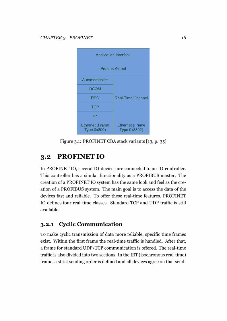
This real-time channel is only based on the Ethernet layer and skips the
rest of the stack. To recognize these special frames, two different ether
types are defined: 0x800 for none real-time communication and 0x8892
for real-time communication. This real-time communication is less pow-
erful as the solution in PROFINET IO. It just speeds up the transmission
by bypassing some parts of the stack but the problems of standard Ether-
net remain untouched (see Section 1.3.1). See Figure 3.1 for an illustration
of the stack variants. [13, p. 33]
CHAPTER 3. PROFINET 16
Figure 3.1: PROFINET CBA stack variants [13, p. 35]
3.2 PROFINET IO
In PROFINET IO, several IO-devices are connected to an IO-controller.
This controller has a similar functionality as a PROFIBUS master. The
creation of a PROFINET IO system has the same look and feel as the cre-
ation of a PROFIBUS system. The main goal is to access the data of the
devices fast and reliable. To offer these real-time features, PROFINET
IO defines four real-time classes. Standard TCP and UDP traffic is still
available.
3.2.1 Cyclic Communication
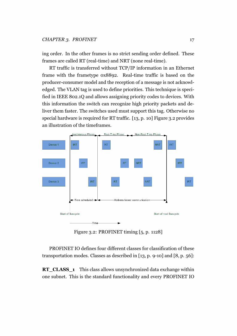
To make cyclic transmission of data more reliable, specific time frames
exist. Within the first frame the real-time traffic is handled. After that,
a frame for standard UDP/TCP communication is offered. The real-time
traffic is also divided into two sections. In the IRT (isochronous real-time)
frame, a strict sending order is defined and all devices agree on that send-
CHAPTER 3. PROFINET 17
ing order. In the other frames is no strict sending order defined. These
frames are called RT (real-time) and NRT (none real-time).
RT traffic is transferred without TCP/IP information in an Ethernet
frame with the frametype 0x8892. Real-time traffic is based on the
producer-consumer model and the reception of a message is not acknowl-
edged. The VLAN tag is used to define priorities. This technique is speci-
fied in IEEE 802.1Q and allows assigning priority codes to devices. With
this information the switch can recognize high priority packets and de-
liver them faster. The switches used must support this tag. Otherwise no
special hardware is required for RT traffic. [13, p. 10] Figure 3.2 provides
an illustration of the timeframes.
Figure 3.2: PROFINET timing [5, p. 1128]
PROFINET IO defines four different classes for classification of these
transportation modes. Classes as described in [13, p. 9-10] and [8, p. 56]:
RT_CLASS_1 This class allows unsynchronized data exchange within
one subnet. This is the standard functionality and every PROFINET IO
CHAPTER 3. PROFINET 18
device supports this class. In this class the beginning of a bus cycle is not
defined. Standard Ethernet switches can be used.
RT_CLASS_2 This class allows the synchronized transfer of data within
one subnet. In this class all devices agree on the same start of a bus inter-
val and react according to that. This class requires PROFINET compatible
switches.
RT_CLASS_3 In this class the isochronous transfer within one sub-
net is supported. A strict sending order is defined. Special hardware is
needed. This class allows bus cycles that are shorter than 1ms and the
jitter of the start of a bus cycle is 1µs. This allows communication in the
highest class motion control defined in Section 1.3.1. The time is defined
by a single clock master that can be integrated into an IO-controller. [13,
p. 17]
The clock synchronization is repeated cyclically and can be divided
into two phases. First the master measures the delay on the transmission
link between to communication partners. After this the master sends a
synchronization frame using a multicast. In this frame the value of the
master clock and the delay of the master clock is included. This informa-
tion is used to synchronize the clocks of the slaves. [11, p. 55-58]
RT_CLASS_UDP This unsynchronized class allows the communica-
tion between different subnets. This is an optional class.
Additional to these classes there are three redundancy classes defined:
RED_CLASS_1 “Ring redundancy for IEEE 802 and IETF commu-
nications combined with the RTE specific additions RT_CLASS_1 and
RT_CLASS_UDP.” [8, p. 56]
CHAPTER 3. PROFINET 19
RED_CLASS_2 “Bumpless1 ring redundancy for RT_CLASS_1 and
RT_CLASS_2.” [8, p. 56]
RED_CLASS_3 “Bumpless ring redundancy for RT_CLASS_3.” [8,
p. 56]
3.2.2 Acyclic Communication
Beside the cyclic RT communication, it is possible to transfer data initi-
ated by an event. The transmission of this data happens over standard
UDP/IP. This can be used to transfer log messages or diagnostics infor-
mation. [13, p. 10]
Alarms are also acyclic high priority messages. The receiver of an
alarm acknowledges the alarm to the sender. There are two different
alarm classes:[13, p. 11]
Process alarms This alarm arises on a condition of the observed pro-
cess (e.g. the temperature is too high). The device itself can be working
correctly but it is also possible that the alarm is triggered because of a
failure in the device.
Diagnostic alarms are used when the device failed.
3.2.3 Addressing
Each device has a symbolic name that is connected to a MAC address.
The IO-controller maps an IP-address to a MAC address based on that
symbolic name.
Beside of that each device has different slots. A slot represents a de-
vice. Each slot can have multiple subslots which can be read bit, byte or
word wise. Each subslot represents a connection to the process the de-
vices is controlling or observing. This numeric value of those subslots is1“in case of a fault a smooth switchover to other communication paths is possible”
[13, p. 26]
CHAPTER 3. PROFINET 20
transmitted in a “bundled” fashion with meta information that allows to
decide if a value is still valid.
With a so called Index it is possible to access the subslots in an acyclic
time interval. The cyclic access is defined by the vendor.
3.2.4 Network Topology
With a switch it is possible to create star networks. It is also possible to in-
tegrate the switch functionality into the devices and equip them with two
plugs. This allows the creation of bus networks. Building a tree network is
also possible. The LLDP (Link Layer Discovery Protocol) protocol discov-
ers the neighbors of a device and recognizes the topology of the network
automatically. [13, p. 14]
3.2.5 Web Integration
PROFINET also offers access to data over HTML and XML. This allows
diagnostics and commissioning over the Internet. The support of HTML
allows human access to this data and XML supports the exchange of in-
formation between computers over the Internet. The Web server needed
for this can be integrated into the device. [13, p. 37]
3.2.6 Security
As it is possible to communicate with the devices over the Internet and it
is possible to support Web integration steps must be taken to ensure the
security in a plant. The devices themselves do not implement a security
concept. Thus everyone has access to the data. To avoid security issues
the network is split into separate segments and the data sent is controlled
by special switches. These switches ensure that only authorized traffic
reaches and leaves a segment. [13, p. 38]
CHAPTER 3. PROFINET 21
3.2.7 Fieldbus Integration
With the help of proxies and gateways it is possible to integrate existing
fieldbuses into a PROFINET network. There exist solutions for PROFIBUS,
Interbus, DeviceNet and others.
4 Conclusion
It seems that nothing can stop the success story of Industrial Ethernet.
Many important vendors already offer products in this area. The solu-
tions fix the weak points of standard Ethernet like indeterminism of the
transmission or the required transmission time.
The standardization process continues and IEC is avoiding an Indus-
trial Ethernet war. The compromise is that there won’t be a single stan-
dard for Industrial Ethernet. This is certainly not a perfect solution and it
would be much nicer to have a single standard like in the office world.
On the other hand the requirements of the industry vary much more.
PROFINET offers integration of older fieldbuses and so do other vendors
of Industrial Ethernet. Thus, it is easier to use this new technology and
integrate it in the existing network.
This integration must be done carefully. The Stuxnet virus shows that
it is possible to spy or sabotage an industrial control system. This virus
directly attacks the PLCs (programmable logic controllers) and the com-
puters that program these devices. This virus managed to infect approx-
imately 100,000 PLCs. [4] When Ethernet based solutions are used it is
even possible that a normal Windows virus infects the network and causes
much problems there. This has to be taken in account and preparations
for that scenario must be taken.
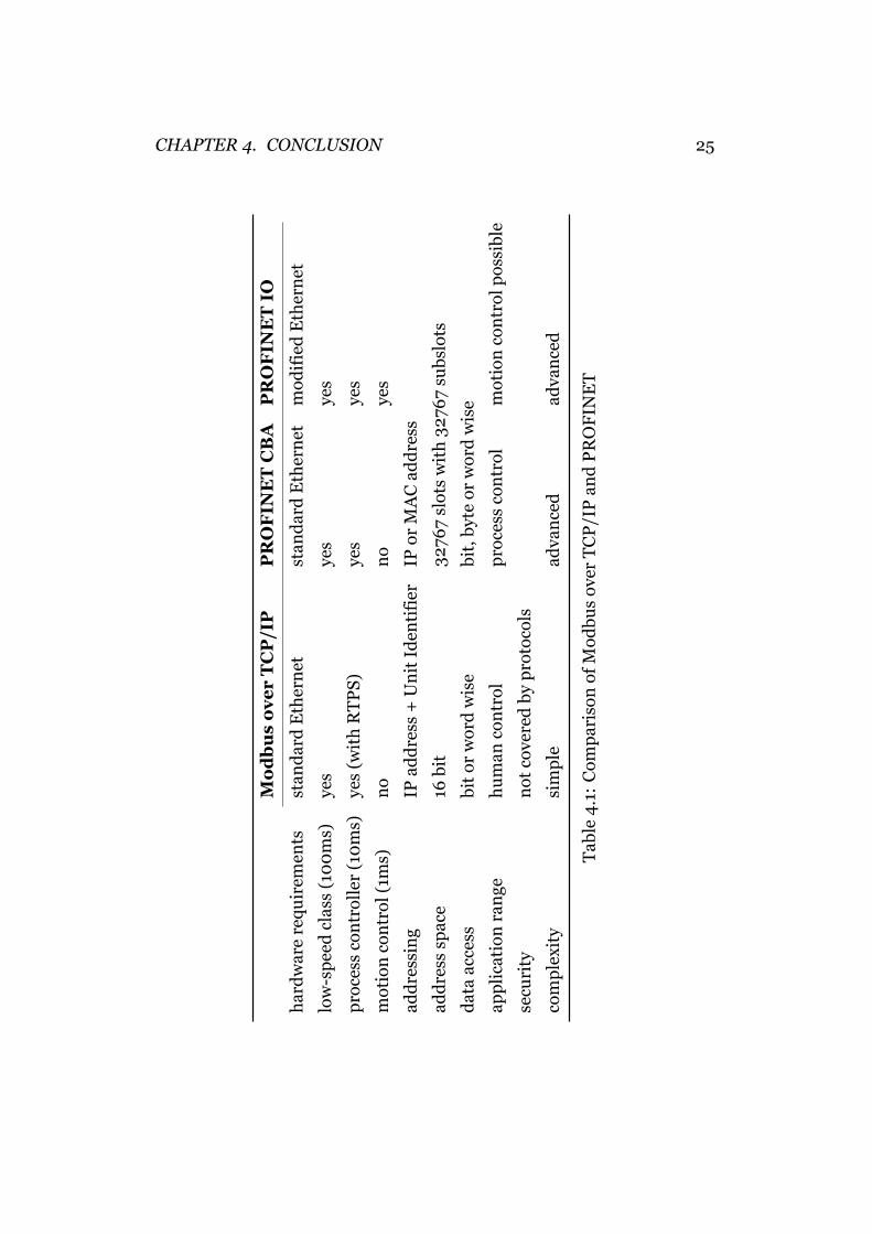
Comparing Modbus over TCP and PROFINET leads to similarities but
also reveals different approaches (see Table 4.1). Both protocols are main-
tained by a group of different vendors and both are a so called open stan-
dard. Beside that, both share the same goals:
• use Ethernet Hardware for communication in industrial context
• simplify access to data over a network
• focus on process automation
But the ways of achieving those common goals are quite different. Com-
paring Modbus over TCP and PROFINET seems actually a bit unfair at the
22
CHAPTER 4. CONCLUSION 23
first glance. Modbus over TCP offers just a very simple protocol to trans-
mit data from one device to another. PROFINET also offers this function-
ality. Additionally, PROFINET covers the development of plants as well
as the monitoring of a running network.
As PROFINET CBA and Modbus over TCP use Ethernet and IP for
communication both support the same address space when it comes to IP
traffic. This allows to build large networks. PROFINET IO uses for real-
time traffic only the Ethernet layer and so there are no IP addresses used.
The MAC address of each device is worldwide unique. This address space
can also be considered big enough for every purpose.
Addressing data in the device reveals differences. Modbus just de-
fines bit and word wise access and allows to address 65536 bits and 65536
words (from 0 to 65535). The address space of PROFINET is much big-
ger. There are 32767 slots where each slot may contain 32767 subslots.
Additionally, PROFINET defines more data types than Modbus.
When it comes to security Modbus over TCP and PROFINET share
a similar approach here. Security isn’t implemented in the devices. To
achieve access restrictions both protocols need special switches that ap-
ply the desired rules to the network traffic. So no protocol has a real ad-
vantage here.
PROFINET has a wider application range as it supports real-time trans-
mission. It is even capable to deliver traffic in the highest transportation
class called the isochronous real-time class. Modbus over TCP can’t com-
pete with PROFINET IO here. In terms of transportation class, it is more
comparable to PROFINET CBA.
But Modbus has also some benefits. It is a very simple protocol that
can be implemented fast and uncomplicated. At the same time, Modbus
is also powerful enough to fulfill the requirements of many applications.
PROFINET IO and CBA together are a more sophisticated protocol but
that brings more complexity along. With Modbus the development of
devices seems more flexible. This might be the reason why it is still so
successful.
CHAPTER 4. CONCLUSION 24
Although Modbus is quite old and a very simple approach it seems
that its success story isn’t over yet. PROFINET is a more sophisticated
solution but has to prove that its accepted by the industry. There were
already 2.1 million PROFINET nodes installed in the end of 2009 [1] but
compared to the more than 31 million devices of PROFIBUS [2] there is
still a long way to go.
CHAPTER 4. CONCLUSION 25
Mo
db
us
ov
er
TC
P/I
PP
RO
FIN
ET
CB
AP
RO
FIN
ET
IO
har
dw
are
requ
irem
ents
stan
dar
d E
ther
net
stan
dar
d E
ther
net
mod
ifie
d E
ther
net
low
-sp
eed
cla
ss (
100
ms)
yes
yes
yes
pro
cess
con
trol
ler
(10
ms)
yes
(wit
h R
TP
S)ye
sye
s
mot
ion
con
trol
(1m
s)n
on
oye
s
add
ress
ing
IPad
dre
ss +
Un
it I
den
tifi
erIP
or M
AC
add
ress
add
ress
sp
ace
16 b
it32
767
slot
s w
ith
327
67
subs
lots
dat
a ac
cess
bit
or w
ord
wis
ebi
t,by
te o
r w
ord
wis
e
app
lica
tion
ran
geh
um
an c
ontr
olp
roce
ss c
ontr
olm
otio
n c
ontr
ol p
ossi
ble
secu
rity
not
cov
ered
by
pro
toco
ls
com
ple
xity
sim
ple
adva
nce
dad
van
ced
Tab
le4
.1:
Com
par
ison
of
Mod
bus
over
TC
P/I
Pan
d P
RO
FIN
ET
Bibliography
[1] PROFINET Overview, 11 2010. URL http://www.profibus.com/
technology/profinet/.
[2] PROFIBUS Overview, 11 2010. URL http://www.profibus.com/
technology/profibus/.
[3] Jean Dominique Decotignie. Ethernet-based real-time and indus-
trial communications. Proc. IEEE, 93(6):1102–1117, June 2005.
[4] Nicolas Falliere, Liam O Murchu, and Eric Chien. Symantec secu-
rity response w32.stuxnet dossier. http://www.symantec.com/
content/en/us/enterprise/media/security_response/
whitepapers/w32_stuxnet_dossier.pdf, November 2010.
[5] Max Felser. Real-Time Ethernet Industry Prospective. Proc. IEEE,
93(6):1118–1129, June 2005.
[6] Max Felser and Thilo Sauter. The fieldbus war: history or short
break between battles? Proc. IEEE Int. Workshop Factory Com-
munication Systems, pages 73–80, 2002.
[7] Max Felser and Thilo Sauter. Standardization of industrial ethernet
- the next battlefield? IEEE, pages 413–421, 2004.
[8] International Electrotechnical Commission. DIN IEC 61784-2, June
2009.
[9] Modbus-IDA. Modbus application protocol specification, December
2006.
[10] Modbus-IDA. Modbus messaging on TCP/IP implementation guide,
October 2006.
[11] Raimond Pigan and Mark Metter. Automating with PROFINET:
Industrial communication based on Industrial Ethernet. Publicis
Publishing, 2008.
26
BIBLIOGRAPHY 27
[12] Martin Polke. Prozeßleittechnik. Oldenbourg Verlag, 1994.
[13] PROFIBUS Nutzerorganisation e.V. PROFINET Systembeschrei-
bung, April 2009.
[14] Kadangode K. Ramakrishnan and Henry Yang. The Ethernet Cap-
ture Effect: Analysis and Solution. Proc. 19th Conf. Local Computer
Networks, pages 228–240, 1994.
[15] Jean Pierre Thomesse. Time and industrial local area networks.
Proc. 7th Annu. Eur. Computer Conf. Computer Design, Manufac-
turing and Production(COMPEURO’ 93), pages 365–374, 1993.
[16] Jean Pierre Thomesse. Fieldbuses and interoperability. Cntr. Eng.
Pract., 7(1):81–94, 1999.


![STUDIEN ZUM NEUEN TESTAMENT UND SEINER UMWELT (SNTU) · The lntroduction to the Rufe [The Master shall teach the sai]nts to live according to the Book of the Community Rule, that](https://img.pdfslide.org/doc/110x75/5e1977167724c777bd16cbcc/studien-zum-neuen-testament-und-seiner-umwelt-sntu-the-lntroduction-to-the-rufe.jpg)


![Highly Resolved Systems Biology to Dissect the Etioplast-to … · Highly Resolved Systems Biology to Dissect the Etioplast-to-Chloroplast Transition in Tobacco Leaves1[OPEN] Tegan](https://img.pdfslide.org/doc/110x75/60474ffbfcc2a01bbe3f74f9/highly-resolved-systems-biology-to-dissect-the-etioplast-to-highly-resolved-systems.jpg)