Embed Size (px)
Citation preview

AKM
Deutsch Synchron ServomotorenEnglish Synchronous ServomotorsItaliano Servomotori SincroniEspañol Servomotores Sincronos
Produkthandbuch / Product Manual / Manuale del Prodotto/ Manual del productoEdition 01/2009European Version (CE region)
File akm_deis.***
Bewahren Sie das Handbuch als Produktbestandteil währendder Lebensdauer des Produktes auf. Geben Sie das Handbuchan nachfolgende Benutzer oder Besitzer des Produktes weiter.
Keep the manual as a product component during the life span ofthe product. Pass the manual to future users / owners of theproduct.
Conservare il manuale per l’intera durata del prodotto. In caso dicambio di proprietà il manuale deve essere fornito al nuovo uti-lizzatore quale parte integrante del prodotto.
Conserve el manual durante toda la vida útil del producto.Entregue el manual a posteriores usuarios o propietarios delproducto.
History
Edition Remarks
01 / 2009 First multilingual edition
Technische Änderungen, die der Verbesserung der Geräte dienen, vorbehalten!Originalbetriebsanleitung, gedruckt in der BRDAlle Rechte vorbehalten. Kein Teil des Werkes darf in irgendeiner Form (Druck, Fotokopie, Mikrofilm oder ineinem anderen Verfahren) ohne schriftliche Genehmigung der Firma Danaher Motion GmbH reproduziertoder unter Verwendung elektronischer Systeme verarbeitet, vervielfältigt oder verbreitet werden.
Technical changes to improve the performance of the equipment may be made without prior notice!Translation of the original manual, printed in the Federal Republic of GermanyAll rights reserved. No part of this work may be reproduced in any form (by printing, photocopying, microfilmor any other method) or stored, processed, copied or distributed by electronic means without the written per-mission of Danaher Motion GmbH.
Il produttore si riserva la facoltà di apportare modifiche tecniche volte al miglioramento degli appa-recchiTraduzione del manuale originale, stampato nella Repubblica federale tedescaTutti i diritti riservati. Nessuna parte di questo documento può essere rielaborata, riprodotta in qualsiasiforma (stampa, fotocopia, microfilm o altro processo) o diffusa mediante l'uso di sistemi elettronici senza l'ap-provazione scritta della ditta Danaher Motion GmbH o rielaborata, riprodotta o diffusa mediante l’uso di sis-temi elettronici.
Reservado el derecho de introducir modificaciones técnicas para la mejora de los equiposTraducción del manual original, iImpreso en la RFAReservados todos los derechos. Prohibida la reproducción total o parcial de la presente obra por cualquiermedio (impresión, fotocopia, microfilm u otros), así como su procesamiento, reproducción y divulgación pormedio de sistemas electrónicos, sin expresa autorización escrita de la empresa Danaher Motion GmbH.e
tocdruck
1 Allgemeines1.1 Über dieses Handbuch. . . . . . . . . . . . . . . . . . . . . . . . . . . . . . . . . . . . . . . . . . . . . . . . . . . . . . . . . . . . . . . . . . . . 91.2 Zielgruppe . . . . . . . . . . . . . . . . . . . . . . . . . . . . . . . . . . . . . . . . . . . . . . . . . . . . . . . . . . . . . . . . . . . . . . . . . . . . . 91.3 Verwendete Symbole . . . . . . . . . . . . . . . . . . . . . . . . . . . . . . . . . . . . . . . . . . . . . . . . . . . . . . . . . . . . . . . . . . . . . 91.4 Verwendete Abkürzungen . . . . . . . . . . . . . . . . . . . . . . . . . . . . . . . . . . . . . . . . . . . . . . . . . . . . . . . . . . . . . . . . . 9
2 Sicherheit2.1 Sicherheitshinweise . . . . . . . . . . . . . . . . . . . . . . . . . . . . . . . . . . . . . . . . . . . . . . . . . . . . . . . . . . . . . . . . . . . . . 102.2 Bestimmungsgemäße Verwendung . . . . . . . . . . . . . . . . . . . . . . . . . . . . . . . . . . . . . . . . . . . . . . . . . . . . . . . . . 112.3 Nicht bestimmungsgemäße Verwendung. . . . . . . . . . . . . . . . . . . . . . . . . . . . . . . . . . . . . . . . . . . . . . . . . . . . . 11
3 Gültige Standards3.1 EG-Konformitätserklärung . . . . . . . . . . . . . . . . . . . . . . . . . . . . . . . . . . . . . . . . . . . . . . . . . . . . . . . . . . . . . . . . 12
4 Handhabung4.1 Transport . . . . . . . . . . . . . . . . . . . . . . . . . . . . . . . . . . . . . . . . . . . . . . . . . . . . . . . . . . . . . . . . . . . . . . . . . . . . . 134.2 Verpackung . . . . . . . . . . . . . . . . . . . . . . . . . . . . . . . . . . . . . . . . . . . . . . . . . . . . . . . . . . . . . . . . . . . . . . . . . . . 134.3 Lagerung . . . . . . . . . . . . . . . . . . . . . . . . . . . . . . . . . . . . . . . . . . . . . . . . . . . . . . . . . . . . . . . . . . . . . . . . . . . . . 134.4 Wartung / Reinigung . . . . . . . . . . . . . . . . . . . . . . . . . . . . . . . . . . . . . . . . . . . . . . . . . . . . . . . . . . . . . . . . . . . . 134.5 Reparatur . . . . . . . . . . . . . . . . . . . . . . . . . . . . . . . . . . . . . . . . . . . . . . . . . . . . . . . . . . . . . . . . . . . . . . . . . . . . . 134.6 Entsorgung. . . . . . . . . . . . . . . . . . . . . . . . . . . . . . . . . . . . . . . . . . . . . . . . . . . . . . . . . . . . . . . . . . . . . . . . . . . . 13
5 Produktidentif izierung5.1 Lieferumfang . . . . . . . . . . . . . . . . . . . . . . . . . . . . . . . . . . . . . . . . . . . . . . . . . . . . . . . . . . . . . . . . . . . . . . . . . . 145.2 Typenschild . . . . . . . . . . . . . . . . . . . . . . . . . . . . . . . . . . . . . . . . . . . . . . . . . . . . . . . . . . . . . . . . . . . . . . . . . . . 145.3 Typenschlüssel . . . . . . . . . . . . . . . . . . . . . . . . . . . . . . . . . . . . . . . . . . . . . . . . . . . . . . . . . . . . . . . . . . . . . . . . 15
6 Technische Beschreibung6.1 Allgemeine technische Daten. . . . . . . . . . . . . . . . . . . . . . . . . . . . . . . . . . . . . . . . . . . . . . . . . . . . . . . . . . . . . . 166.2 Standardausrüstung. . . . . . . . . . . . . . . . . . . . . . . . . . . . . . . . . . . . . . . . . . . . . . . . . . . . . . . . . . . . . . . . . . . . . 16
6.2.1 Bauform . . . . . . . . . . . . . . . . . . . . . . . . . . . . . . . . . . . . . . . . . . . . . . . . . . . . . . . . . . . . . . . . . . . . . . . . . 166.2.2 Flansch . . . . . . . . . . . . . . . . . . . . . . . . . . . . . . . . . . . . . . . . . . . . . . . . . . . . . . . . . . . . . . . . . . . . . . . . . 166.2.3 Schutzart . . . . . . . . . . . . . . . . . . . . . . . . . . . . . . . . . . . . . . . . . . . . . . . . . . . . . . . . . . . . . . . . . . . . . . . . 166.2.4 Isolierstoffklasse . . . . . . . . . . . . . . . . . . . . . . . . . . . . . . . . . . . . . . . . . . . . . . . . . . . . . . . . . . . . . . . . . . 166.2.5 Oberfläche . . . . . . . . . . . . . . . . . . . . . . . . . . . . . . . . . . . . . . . . . . . . . . . . . . . . . . . . . . . . . . . . . . . . . . . 166.2.6 Wellenende A-Seite . . . . . . . . . . . . . . . . . . . . . . . . . . . . . . . . . . . . . . . . . . . . . . . . . . . . . . . . . . . . . . . . 176.2.7 Schutzeinrichtung . . . . . . . . . . . . . . . . . . . . . . . . . . . . . . . . . . . . . . . . . . . . . . . . . . . . . . . . . . . . . . . . . 176.2.8 Schwinggüte . . . . . . . . . . . . . . . . . . . . . . . . . . . . . . . . . . . . . . . . . . . . . . . . . . . . . . . . . . . . . . . . . . . . . 176.2.9 Haltebremse. . . . . . . . . . . . . . . . . . . . . . . . . . . . . . . . . . . . . . . . . . . . . . . . . . . . . . . . . . . . . . . . . . . . . . 17
7 Mechanische Installation7.1 Wichtige Hinweise . . . . . . . . . . . . . . . . . . . . . . . . . . . . . . . . . . . . . . . . . . . . . . . . . . . . . . . . . . . . . . . . . . . . . . 18
8 Elektrische Installation8.1 Sicherheitshinweise . . . . . . . . . . . . . . . . . . . . . . . . . . . . . . . . . . . . . . . . . . . . . . . . . . . . . . . . . . . . . . . . . . . . . 198.2 Leitfaden für die elektrische Installation . . . . . . . . . . . . . . . . . . . . . . . . . . . . . . . . . . . . . . . . . . . . . . . . . . . . . . 198.3 Anschluss der Motoren mit vorkonfektionierten Kabeln . . . . . . . . . . . . . . . . . . . . . . . . . . . . . . . . . . . . . . . . . . 20
9 Inbetriebnahme9.1 Wichtige Hinweise . . . . . . . . . . . . . . . . . . . . . . . . . . . . . . . . . . . . . . . . . . . . . . . . . . . . . . . . . . . . . . . . . . . . . . 219.2 Leitfaden für die Inbetriebnahme . . . . . . . . . . . . . . . . . . . . . . . . . . . . . . . . . . . . . . . . . . . . . . . . . . . . . . . . . . . 219.3 Beseitigen von Störungen . . . . . . . . . . . . . . . . . . . . . . . . . . . . . . . . . . . . . . . . . . . . . . . . . . . . . . . . . . . . . . . . 22
10 Technische Daten10.1 Begriffsdefinitionen. . . . . . . . . . . . . . . . . . . . . . . . . . . . . . . . . . . . . . . . . . . . . . . . . . . . . . . . . . . . . . . . . . . . . . 2310.2 AKM1 . . . . . . . . . . . . . . . . . . . . . . . . . . . . . . . . . . . . . . . . . . . . . . . . . . . . . . . . . . . . . . . . . . . . . . . . . . . . . . . . 2410.3 AKM2 . . . . . . . . . . . . . . . . . . . . . . . . . . . . . . . . . . . . . . . . . . . . . . . . . . . . . . . . . . . . . . . . . . . . . . . . . . . . . . . . 2510.4 AKM3 . . . . . . . . . . . . . . . . . . . . . . . . . . . . . . . . . . . . . . . . . . . . . . . . . . . . . . . . . . . . . . . . . . . . . . . . . . . . . . . . 2610.5 AKM4 . . . . . . . . . . . . . . . . . . . . . . . . . . . . . . . . . . . . . . . . . . . . . . . . . . . . . . . . . . . . . . . . . . . . . . . . . . . . . . . . 2710.6 AKM5 . . . . . . . . . . . . . . . . . . . . . . . . . . . . . . . . . . . . . . . . . . . . . . . . . . . . . . . . . . . . . . . . . . . . . . . . . . . . . . . . 2810.7 AKM6 . . . . . . . . . . . . . . . . . . . . . . . . . . . . . . . . . . . . . . . . . . . . . . . . . . . . . . . . . . . . . . . . . . . . . . . . . . . . . . . . 2910.8 AKM7 . . . . . . . . . . . . . . . . . . . . . . . . . . . . . . . . . . . . . . . . . . . . . . . . . . . . . . . . . . . . . . . . . . . . . . . . . . . . . . . . 30
Servomotoren AKM Deutsch - 3
Kollmorgen 01/2009 Inhaltsverzeichnis
Seite
DE
UT
SC
H
11 General11.1 About this manual . . . . . . . . . . . . . . . . . . . . . . . . . . . . . . . . . . . . . . . . . . . . . . . . . . . . . . . . . . . . . . . . . . . . . . 3111.2 Target group . . . . . . . . . . . . . . . . . . . . . . . . . . . . . . . . . . . . . . . . . . . . . . . . . . . . . . . . . . . . . . . . . . . . . . . . . . 3111.3 Symbols used. . . . . . . . . . . . . . . . . . . . . . . . . . . . . . . . . . . . . . . . . . . . . . . . . . . . . . . . . . . . . . . . . . . . . . . . . . 3111.4 Abbreviations used. . . . . . . . . . . . . . . . . . . . . . . . . . . . . . . . . . . . . . . . . . . . . . . . . . . . . . . . . . . . . . . . . . . . . . 31
12 Safety12.1 Safety Notes. . . . . . . . . . . . . . . . . . . . . . . . . . . . . . . . . . . . . . . . . . . . . . . . . . . . . . . . . . . . . . . . . . . . . . . . . . . 3212.2 Use as directed . . . . . . . . . . . . . . . . . . . . . . . . . . . . . . . . . . . . . . . . . . . . . . . . . . . . . . . . . . . . . . . . . . . . . . . . 3312.3 Prohibited use . . . . . . . . . . . . . . . . . . . . . . . . . . . . . . . . . . . . . . . . . . . . . . . . . . . . . . . . . . . . . . . . . . . . . . . . . 33
13 Standards13.1 EC Declaration of Conformity. . . . . . . . . . . . . . . . . . . . . . . . . . . . . . . . . . . . . . . . . . . . . . . . . . . . . . . . . . . . . . 34
14 Handling14.1 Transport . . . . . . . . . . . . . . . . . . . . . . . . . . . . . . . . . . . . . . . . . . . . . . . . . . . . . . . . . . . . . . . . . . . . . . . . . . . . . 3514.2 Packaging . . . . . . . . . . . . . . . . . . . . . . . . . . . . . . . . . . . . . . . . . . . . . . . . . . . . . . . . . . . . . . . . . . . . . . . . . . . . 3514.3 Storage . . . . . . . . . . . . . . . . . . . . . . . . . . . . . . . . . . . . . . . . . . . . . . . . . . . . . . . . . . . . . . . . . . . . . . . . . . . . . . 3514.4 Maintenance / Cleaning . . . . . . . . . . . . . . . . . . . . . . . . . . . . . . . . . . . . . . . . . . . . . . . . . . . . . . . . . . . . . . . . . . 3514.5 Repair . . . . . . . . . . . . . . . . . . . . . . . . . . . . . . . . . . . . . . . . . . . . . . . . . . . . . . . . . . . . . . . . . . . . . . . . . . . . . . . 3514.6 Disposal . . . . . . . . . . . . . . . . . . . . . . . . . . . . . . . . . . . . . . . . . . . . . . . . . . . . . . . . . . . . . . . . . . . . . . . . . . . . . . 35
15 Package15.1 Delivery package . . . . . . . . . . . . . . . . . . . . . . . . . . . . . . . . . . . . . . . . . . . . . . . . . . . . . . . . . . . . . . . . . . . . . . . 3615.2 Nameplate . . . . . . . . . . . . . . . . . . . . . . . . . . . . . . . . . . . . . . . . . . . . . . . . . . . . . . . . . . . . . . . . . . . . . . . . . . . . 3615.3 Model number description . . . . . . . . . . . . . . . . . . . . . . . . . . . . . . . . . . . . . . . . . . . . . . . . . . . . . . . . . . . . . . . . 37
16 Technical Description16.1 General technical data . . . . . . . . . . . . . . . . . . . . . . . . . . . . . . . . . . . . . . . . . . . . . . . . . . . . . . . . . . . . . . . . . . . 3816.2 Standard features. . . . . . . . . . . . . . . . . . . . . . . . . . . . . . . . . . . . . . . . . . . . . . . . . . . . . . . . . . . . . . . . . . . . . . . 38
16.2.1 Style. . . . . . . . . . . . . . . . . . . . . . . . . . . . . . . . . . . . . . . . . . . . . . . . . . . . . . . . . . . . . . . . . . . . . . . . . . . . 3816.2.2 Flange . . . . . . . . . . . . . . . . . . . . . . . . . . . . . . . . . . . . . . . . . . . . . . . . . . . . . . . . . . . . . . . . . . . . . . . . . . 3816.2.3 Protection class . . . . . . . . . . . . . . . . . . . . . . . . . . . . . . . . . . . . . . . . . . . . . . . . . . . . . . . . . . . . . . . . . . . 3816.2.4 Insulation material class. . . . . . . . . . . . . . . . . . . . . . . . . . . . . . . . . . . . . . . . . . . . . . . . . . . . . . . . . . . . . 3816.2.5 Surface . . . . . . . . . . . . . . . . . . . . . . . . . . . . . . . . . . . . . . . . . . . . . . . . . . . . . . . . . . . . . . . . . . . . . . . . . 3816.2.6 Shaft end, A-side . . . . . . . . . . . . . . . . . . . . . . . . . . . . . . . . . . . . . . . . . . . . . . . . . . . . . . . . . . . . . . . . . . 3916.2.7 Protective device . . . . . . . . . . . . . . . . . . . . . . . . . . . . . . . . . . . . . . . . . . . . . . . . . . . . . . . . . . . . . . . . . . 3916.2.8 Vibration class . . . . . . . . . . . . . . . . . . . . . . . . . . . . . . . . . . . . . . . . . . . . . . . . . . . . . . . . . . . . . . . . . . . . 3916.2.9 Holding brake. . . . . . . . . . . . . . . . . . . . . . . . . . . . . . . . . . . . . . . . . . . . . . . . . . . . . . . . . . . . . . . . . . . . . 39
17 Mechanical Installation17.1 Important Notes . . . . . . . . . . . . . . . . . . . . . . . . . . . . . . . . . . . . . . . . . . . . . . . . . . . . . . . . . . . . . . . . . . . . . . . . 40
18 Electrical Installation18.1 Safety notes . . . . . . . . . . . . . . . . . . . . . . . . . . . . . . . . . . . . . . . . . . . . . . . . . . . . . . . . . . . . . . . . . . . . . . . . . . . 4118.2 Guide for electrical installation . . . . . . . . . . . . . . . . . . . . . . . . . . . . . . . . . . . . . . . . . . . . . . . . . . . . . . . . . . . . . 4118.3 Connection of the motors with preassembled cables. . . . . . . . . . . . . . . . . . . . . . . . . . . . . . . . . . . . . . . . . . . . 42
19 Setup19.1 Important notes . . . . . . . . . . . . . . . . . . . . . . . . . . . . . . . . . . . . . . . . . . . . . . . . . . . . . . . . . . . . . . . . . . . . . . . . 4319.2 Guide for setup. . . . . . . . . . . . . . . . . . . . . . . . . . . . . . . . . . . . . . . . . . . . . . . . . . . . . . . . . . . . . . . . . . . . . . . . . 4319.3 Trouble Shooting . . . . . . . . . . . . . . . . . . . . . . . . . . . . . . . . . . . . . . . . . . . . . . . . . . . . . . . . . . . . . . . . . . . . . . . 44
20 Technical Data20.1 Definition of Terms. . . . . . . . . . . . . . . . . . . . . . . . . . . . . . . . . . . . . . . . . . . . . . . . . . . . . . . . . . . . . . . . . . . . . . 4520.2 AKM1 . . . . . . . . . . . . . . . . . . . . . . . . . . . . . . . . . . . . . . . . . . . . . . . . . . . . . . . . . . . . . . . . . . . . . . . . . . . . . . . . 4620.3 AKM2 . . . . . . . . . . . . . . . . . . . . . . . . . . . . . . . . . . . . . . . . . . . . . . . . . . . . . . . . . . . . . . . . . . . . . . . . . . . . . . . . 4720.4 AKM3 . . . . . . . . . . . . . . . . . . . . . . . . . . . . . . . . . . . . . . . . . . . . . . . . . . . . . . . . . . . . . . . . . . . . . . . . . . . . . . . . 4820.5 AKM4 . . . . . . . . . . . . . . . . . . . . . . . . . . . . . . . . . . . . . . . . . . . . . . . . . . . . . . . . . . . . . . . . . . . . . . . . . . . . . . . . 4920.6 AKM5 . . . . . . . . . . . . . . . . . . . . . . . . . . . . . . . . . . . . . . . . . . . . . . . . . . . . . . . . . . . . . . . . . . . . . . . . . . . . . . . . 5020.7 AKM6 . . . . . . . . . . . . . . . . . . . . . . . . . . . . . . . . . . . . . . . . . . . . . . . . . . . . . . . . . . . . . . . . . . . . . . . . . . . . . . . . 5120.8 AKM7 . . . . . . . . . . . . . . . . . . . . . . . . . . . . . . . . . . . . . . . . . . . . . . . . . . . . . . . . . . . . . . . . . . . . . . . . . . . . . . . . 52
English - 4 Servomotors AKM
Contents 01/2009 Kollmorgen
Page
EN
GL
ISH
21 Indicazoni generali21.1 Questo manuale. . . . . . . . . . . . . . . . . . . . . . . . . . . . . . . . . . . . . . . . . . . . . . . . . . . . . . . . . . . . . . . . . . . . . . . . 5321.2 Gruppo di obiettivo . . . . . . . . . . . . . . . . . . . . . . . . . . . . . . . . . . . . . . . . . . . . . . . . . . . . . . . . . . . . . . . . . . . . . . 5321.3 Simboli utilizzati . . . . . . . . . . . . . . . . . . . . . . . . . . . . . . . . . . . . . . . . . . . . . . . . . . . . . . . . . . . . . . . . . . . . . . . . 5321.4 Abbreviazioni utilizzati . . . . . . . . . . . . . . . . . . . . . . . . . . . . . . . . . . . . . . . . . . . . . . . . . . . . . . . . . . . . . . . . . . . 53
22 Sicurezza22.1 Indicazioni di sicurezza . . . . . . . . . . . . . . . . . . . . . . . . . . . . . . . . . . . . . . . . . . . . . . . . . . . . . . . . . . . . . . . . . . 5422.2 Uso conforme. . . . . . . . . . . . . . . . . . . . . . . . . . . . . . . . . . . . . . . . . . . . . . . . . . . . . . . . . . . . . . . . . . . . . . . . . . 5522.3 Uso conforme vietato . . . . . . . . . . . . . . . . . . . . . . . . . . . . . . . . . . . . . . . . . . . . . . . . . . . . . . . . . . . . . . . . . . . . 55
23 Norme validi23.1 EC Declaration of Conformity. . . . . . . . . . . . . . . . . . . . . . . . . . . . . . . . . . . . . . . . . . . . . . . . . . . . . . . . . . . . . . 56
24 Maneggiamento24.1 Trasporto . . . . . . . . . . . . . . . . . . . . . . . . . . . . . . . . . . . . . . . . . . . . . . . . . . . . . . . . . . . . . . . . . . . . . . . . . . . . . 5724.2 Imballaggio. . . . . . . . . . . . . . . . . . . . . . . . . . . . . . . . . . . . . . . . . . . . . . . . . . . . . . . . . . . . . . . . . . . . . . . . . . . . 5724.3 Stoccaggio . . . . . . . . . . . . . . . . . . . . . . . . . . . . . . . . . . . . . . . . . . . . . . . . . . . . . . . . . . . . . . . . . . . . . . . . . . . . 5724.4 Manutenzione / Puliza . . . . . . . . . . . . . . . . . . . . . . . . . . . . . . . . . . . . . . . . . . . . . . . . . . . . . . . . . . . . . . . . . . . 5724.5 Riparazioni . . . . . . . . . . . . . . . . . . . . . . . . . . . . . . . . . . . . . . . . . . . . . . . . . . . . . . . . . . . . . . . . . . . . . . . . . . . . 5724.6 Smaltimento . . . . . . . . . . . . . . . . . . . . . . . . . . . . . . . . . . . . . . . . . . . . . . . . . . . . . . . . . . . . . . . . . . . . . . . . . . . 57
25 Identif icazione del prodotto25.1 Dotazione. . . . . . . . . . . . . . . . . . . . . . . . . . . . . . . . . . . . . . . . . . . . . . . . . . . . . . . . . . . . . . . . . . . . . . . . . . . . . 5825.2 Targhetta di omologazione. . . . . . . . . . . . . . . . . . . . . . . . . . . . . . . . . . . . . . . . . . . . . . . . . . . . . . . . . . . . . . . . 5825.3 Codici dei modelli . . . . . . . . . . . . . . . . . . . . . . . . . . . . . . . . . . . . . . . . . . . . . . . . . . . . . . . . . . . . . . . . . . . . . . . 59
26 Descrizione tecnizi26.1 Dati tecnici generali . . . . . . . . . . . . . . . . . . . . . . . . . . . . . . . . . . . . . . . . . . . . . . . . . . . . . . . . . . . . . . . . . . . . . 6026.2 Allestimento standard. . . . . . . . . . . . . . . . . . . . . . . . . . . . . . . . . . . . . . . . . . . . . . . . . . . . . . . . . . . . . . . . . . . . 60
26.2.1 Forma costructtiva . . . . . . . . . . . . . . . . . . . . . . . . . . . . . . . . . . . . . . . . . . . . . . . . . . . . . . . . . . . . . . . . . 6026.2.2 Flangia . . . . . . . . . . . . . . . . . . . . . . . . . . . . . . . . . . . . . . . . . . . . . . . . . . . . . . . . . . . . . . . . . . . . . . . . . . 6026.2.3 Grado di protezione . . . . . . . . . . . . . . . . . . . . . . . . . . . . . . . . . . . . . . . . . . . . . . . . . . . . . . . . . . . . . . . . 6026.2.4 Classe di isolamento . . . . . . . . . . . . . . . . . . . . . . . . . . . . . . . . . . . . . . . . . . . . . . . . . . . . . . . . . . . . . . . 6026.2.5 Superficie . . . . . . . . . . . . . . . . . . . . . . . . . . . . . . . . . . . . . . . . . . . . . . . . . . . . . . . . . . . . . . . . . . . . . . . 6026.2.6 Estremità di uscita albero. . . . . . . . . . . . . . . . . . . . . . . . . . . . . . . . . . . . . . . . . . . . . . . . . . . . . . . . . . . . 6126.2.7 Dispositivo di protezione . . . . . . . . . . . . . . . . . . . . . . . . . . . . . . . . . . . . . . . . . . . . . . . . . . . . . . . . . . . . 6126.2.8 Resistenza alle vibrazioni. . . . . . . . . . . . . . . . . . . . . . . . . . . . . . . . . . . . . . . . . . . . . . . . . . . . . . . . . . . . 6126.2.9 Freno di stazionamento . . . . . . . . . . . . . . . . . . . . . . . . . . . . . . . . . . . . . . . . . . . . . . . . . . . . . . . . . . . . . 61
27 Installazione meccanica27.1 Indicazioni importanti . . . . . . . . . . . . . . . . . . . . . . . . . . . . . . . . . . . . . . . . . . . . . . . . . . . . . . . . . . . . . . . . . . . . 62
28 Installazione elettrica28.1 Indicazioni di sicurezza . . . . . . . . . . . . . . . . . . . . . . . . . . . . . . . . . . . . . . . . . . . . . . . . . . . . . . . . . . . . . . . . . . 6328.2 Guida ad installazione elettrica . . . . . . . . . . . . . . . . . . . . . . . . . . . . . . . . . . . . . . . . . . . . . . . . . . . . . . . . . . . . 6328.3 Collegamento dei motori . . . . . . . . . . . . . . . . . . . . . . . . . . . . . . . . . . . . . . . . . . . . . . . . . . . . . . . . . . . . . . . . . 64
29 Messa in funzione29.1 Indicazioni importanti . . . . . . . . . . . . . . . . . . . . . . . . . . . . . . . . . . . . . . . . . . . . . . . . . . . . . . . . . . . . . . . . . . . . 6529.2 Guida ad messa in funzione. . . . . . . . . . . . . . . . . . . . . . . . . . . . . . . . . . . . . . . . . . . . . . . . . . . . . . . . . . . . . . . 6529.3 Eliminazione dei guasti . . . . . . . . . . . . . . . . . . . . . . . . . . . . . . . . . . . . . . . . . . . . . . . . . . . . . . . . . . . . . . . . . . 66
30 Dati tecnici30.1 Definizioni . . . . . . . . . . . . . . . . . . . . . . . . . . . . . . . . . . . . . . . . . . . . . . . . . . . . . . . . . . . . . . . . . . . . . . . . . . . . 6730.2 AKM1 . . . . . . . . . . . . . . . . . . . . . . . . . . . . . . . . . . . . . . . . . . . . . . . . . . . . . . . . . . . . . . . . . . . . . . . . . . . . . . . . 6830.3 AKM2 . . . . . . . . . . . . . . . . . . . . . . . . . . . . . . . . . . . . . . . . . . . . . . . . . . . . . . . . . . . . . . . . . . . . . . . . . . . . . . . . 6930.4 AKM3 . . . . . . . . . . . . . . . . . . . . . . . . . . . . . . . . . . . . . . . . . . . . . . . . . . . . . . . . . . . . . . . . . . . . . . . . . . . . . . . . 7030.5 AKM4 . . . . . . . . . . . . . . . . . . . . . . . . . . . . . . . . . . . . . . . . . . . . . . . . . . . . . . . . . . . . . . . . . . . . . . . . . . . . . . . . 7130.6 AKM5 . . . . . . . . . . . . . . . . . . . . . . . . . . . . . . . . . . . . . . . . . . . . . . . . . . . . . . . . . . . . . . . . . . . . . . . . . . . . . . . . 7230.7 AKM6 . . . . . . . . . . . . . . . . . . . . . . . . . . . . . . . . . . . . . . . . . . . . . . . . . . . . . . . . . . . . . . . . . . . . . . . . . . . . . . . . 7330.8 AKM7 . . . . . . . . . . . . . . . . . . . . . . . . . . . . . . . . . . . . . . . . . . . . . . . . . . . . . . . . . . . . . . . . . . . . . . . . . . . . . . . . 74
Servomotori AKM Italiano - 5
Kollmorgen 01/2009 Indice
Pagina
ITA
LIA
NO
31 Generalidades31.1 Sobre este manual . . . . . . . . . . . . . . . . . . . . . . . . . . . . . . . . . . . . . . . . . . . . . . . . . . . . . . . . . . . . . . . . . . . . . . 7531.2 Destinatarios . . . . . . . . . . . . . . . . . . . . . . . . . . . . . . . . . . . . . . . . . . . . . . . . . . . . . . . . . . . . . . . . . . . . . . . . . . 7531.3 Símbolos utilizados . . . . . . . . . . . . . . . . . . . . . . . . . . . . . . . . . . . . . . . . . . . . . . . . . . . . . . . . . . . . . . . . . . . . . 7531.4 Abreviaturas utilizadas . . . . . . . . . . . . . . . . . . . . . . . . . . . . . . . . . . . . . . . . . . . . . . . . . . . . . . . . . . . . . . . . . . . 75
32 Seguridad32.1 Instrucciones de seguridad . . . . . . . . . . . . . . . . . . . . . . . . . . . . . . . . . . . . . . . . . . . . . . . . . . . . . . . . . . . . . . . 7632.2 Utilización conforme. . . . . . . . . . . . . . . . . . . . . . . . . . . . . . . . . . . . . . . . . . . . . . . . . . . . . . . . . . . . . . . . . . . . . 7732.3 Uso indebido . . . . . . . . . . . . . . . . . . . . . . . . . . . . . . . . . . . . . . . . . . . . . . . . . . . . . . . . . . . . . . . . . . . . . . . . . . 77
33 Normas válidas33.1 EC Declaration of Conformity. . . . . . . . . . . . . . . . . . . . . . . . . . . . . . . . . . . . . . . . . . . . . . . . . . . . . . . . . . . . . . 78
34 Manipulación34.1 Transporte . . . . . . . . . . . . . . . . . . . . . . . . . . . . . . . . . . . . . . . . . . . . . . . . . . . . . . . . . . . . . . . . . . . . . . . . . . . . 7934.2 Embalaje . . . . . . . . . . . . . . . . . . . . . . . . . . . . . . . . . . . . . . . . . . . . . . . . . . . . . . . . . . . . . . . . . . . . . . . . . . . . . 7934.3 Almacenamiento . . . . . . . . . . . . . . . . . . . . . . . . . . . . . . . . . . . . . . . . . . . . . . . . . . . . . . . . . . . . . . . . . . . . . . . 7934.4 Advertenzia / Limpieza. . . . . . . . . . . . . . . . . . . . . . . . . . . . . . . . . . . . . . . . . . . . . . . . . . . . . . . . . . . . . . . . . . . 7934.5 Reparación. . . . . . . . . . . . . . . . . . . . . . . . . . . . . . . . . . . . . . . . . . . . . . . . . . . . . . . . . . . . . . . . . . . . . . . . . . . . 7934.6 Eliminación. . . . . . . . . . . . . . . . . . . . . . . . . . . . . . . . . . . . . . . . . . . . . . . . . . . . . . . . . . . . . . . . . . . . . . . . . . . . 79
35 Identif icación del producto35.1 Volumen de suministro. . . . . . . . . . . . . . . . . . . . . . . . . . . . . . . . . . . . . . . . . . . . . . . . . . . . . . . . . . . . . . . . . . . 8035.2 Placa de identificación . . . . . . . . . . . . . . . . . . . . . . . . . . . . . . . . . . . . . . . . . . . . . . . . . . . . . . . . . . . . . . . . . . . 8035.3 Codificación de modelo . . . . . . . . . . . . . . . . . . . . . . . . . . . . . . . . . . . . . . . . . . . . . . . . . . . . . . . . . . . . . . . . . . 81
36 Descripción técnica36.1 Datos técnicos generales. . . . . . . . . . . . . . . . . . . . . . . . . . . . . . . . . . . . . . . . . . . . . . . . . . . . . . . . . . . . . . . . . 8236.2 Modelo estándar . . . . . . . . . . . . . . . . . . . . . . . . . . . . . . . . . . . . . . . . . . . . . . . . . . . . . . . . . . . . . . . . . . . . . . . 82
36.2.1 Forma de diseño . . . . . . . . . . . . . . . . . . . . . . . . . . . . . . . . . . . . . . . . . . . . . . . . . . . . . . . . . . . . . . . . . . 8236.2.2 Brida . . . . . . . . . . . . . . . . . . . . . . . . . . . . . . . . . . . . . . . . . . . . . . . . . . . . . . . . . . . . . . . . . . . . . . . . . . . 8236.2.3 Tipo de protección . . . . . . . . . . . . . . . . . . . . . . . . . . . . . . . . . . . . . . . . . . . . . . . . . . . . . . . . . . . . . . . . . 8236.2.4 Clase de material aislante . . . . . . . . . . . . . . . . . . . . . . . . . . . . . . . . . . . . . . . . . . . . . . . . . . . . . . . . . . . 8236.2.5 Superficie . . . . . . . . . . . . . . . . . . . . . . . . . . . . . . . . . . . . . . . . . . . . . . . . . . . . . . . . . . . . . . . . . . . . . . . . 8236.2.6 Extremo del eje, lado de accionamiento . . . . . . . . . . . . . . . . . . . . . . . . . . . . . . . . . . . . . . . . . . . . . . . . 8336.2.7 Dispositivo protector . . . . . . . . . . . . . . . . . . . . . . . . . . . . . . . . . . . . . . . . . . . . . . . . . . . . . . . . . . . . . . . 8336.2.8 Calidad vibracional. . . . . . . . . . . . . . . . . . . . . . . . . . . . . . . . . . . . . . . . . . . . . . . . . . . . . . . . . . . . . . . . . 8336.2.9 Freno de detención . . . . . . . . . . . . . . . . . . . . . . . . . . . . . . . . . . . . . . . . . . . . . . . . . . . . . . . . . . . . . . . . 83
37 Instalación mecánica37.1 Instrucciones importantes . . . . . . . . . . . . . . . . . . . . . . . . . . . . . . . . . . . . . . . . . . . . . . . . . . . . . . . . . . . . . . . . 84
38 Instalación eléctrica38.1 Instrucciones de seguridad . . . . . . . . . . . . . . . . . . . . . . . . . . . . . . . . . . . . . . . . . . . . . . . . . . . . . . . . . . . . . . . 8538.2 Guía de instalación eléctrica . . . . . . . . . . . . . . . . . . . . . . . . . . . . . . . . . . . . . . . . . . . . . . . . . . . . . . . . . . . . . . 8538.3 Conexión de los motores . . . . . . . . . . . . . . . . . . . . . . . . . . . . . . . . . . . . . . . . . . . . . . . . . . . . . . . . . . . . . . . . . 86
39 Puesta en funcionamento39.1 Instrucciones importantes . . . . . . . . . . . . . . . . . . . . . . . . . . . . . . . . . . . . . . . . . . . . . . . . . . . . . . . . . . . . . . . . 8739.2 Guía de puesta en funcionamento . . . . . . . . . . . . . . . . . . . . . . . . . . . . . . . . . . . . . . . . . . . . . . . . . . . . . . . . . . 8739.3 Eliminación de perturbaciones . . . . . . . . . . . . . . . . . . . . . . . . . . . . . . . . . . . . . . . . . . . . . . . . . . . . . . . . . . . . . 88
40 Datos técnicos40.1 Definiciones . . . . . . . . . . . . . . . . . . . . . . . . . . . . . . . . . . . . . . . . . . . . . . . . . . . . . . . . . . . . . . . . . . . . . . . . . . . 8940.2 AKM1 . . . . . . . . . . . . . . . . . . . . . . . . . . . . . . . . . . . . . . . . . . . . . . . . . . . . . . . . . . . . . . . . . . . . . . . . . . . . . . . . 9040.3 AKM2 . . . . . . . . . . . . . . . . . . . . . . . . . . . . . . . . . . . . . . . . . . . . . . . . . . . . . . . . . . . . . . . . . . . . . . . . . . . . . . . . 9140.4 AKM3 . . . . . . . . . . . . . . . . . . . . . . . . . . . . . . . . . . . . . . . . . . . . . . . . . . . . . . . . . . . . . . . . . . . . . . . . . . . . . . . . 9240.5 AKM4 . . . . . . . . . . . . . . . . . . . . . . . . . . . . . . . . . . . . . . . . . . . . . . . . . . . . . . . . . . . . . . . . . . . . . . . . . . . . . . . . 9340.6 AKM5 . . . . . . . . . . . . . . . . . . . . . . . . . . . . . . . . . . . . . . . . . . . . . . . . . . . . . . . . . . . . . . . . . . . . . . . . . . . . . . . . 9440.7 AKM6 . . . . . . . . . . . . . . . . . . . . . . . . . . . . . . . . . . . . . . . . . . . . . . . . . . . . . . . . . . . . . . . . . . . . . . . . . . . . . . . . 9540.8 AKM7 . . . . . . . . . . . . . . . . . . . . . . . . . . . . . . . . . . . . . . . . . . . . . . . . . . . . . . . . . . . . . . . . . . . . . . . . . . . . . . . . 96
Español - 6 Servomotores AKM
Sumario 01/2009 Kollmorgen
Página
ES
PA
ÑO
L
41 Appendix41.1 Wiring Diagram Motor & Resolver . . . . . . . . . . . . . . . . . . . . . . . . . . . . . . . . . . . . . . . . . . . . . . . . . . . . . . . . . . 9741.2 Wiring Diagram Motor & Encoder with EnDat (ECx, EQx) . . . . . . . . . . . . . . . . . . . . . . . . . . . . . . . . . . . . . . . . 9841.3 Wiring Diagram Motor & Smart Feedback Device (SFD) . . . . . . . . . . . . . . . . . . . . . . . . . . . . . . . . . . . . . . . . . 9941.4 Wiring Diagram Motor & ComCoder. . . . . . . . . . . . . . . . . . . . . . . . . . . . . . . . . . . . . . . . . . . . . . . . . . . . . . . . 10041.5 Wiring Diagram Motor & Encoder with BISS . . . . . . . . . . . . . . . . . . . . . . . . . . . . . . . . . . . . . . . . . . . . . . . . . 10141.6 Dimensions AKM1 . . . . . . . . . . . . . . . . . . . . . . . . . . . . . . . . . . . . . . . . . . . . . . . . . . . . . . . . . . . . . . . . . . . . . 10241.7 Dimensions AKM2 . . . . . . . . . . . . . . . . . . . . . . . . . . . . . . . . . . . . . . . . . . . . . . . . . . . . . . . . . . . . . . . . . . . . . 10341.8 Dimensions AKM3 . . . . . . . . . . . . . . . . . . . . . . . . . . . . . . . . . . . . . . . . . . . . . . . . . . . . . . . . . . . . . . . . . . . . . 10441.9 Dimensions AKM4 . . . . . . . . . . . . . . . . . . . . . . . . . . . . . . . . . . . . . . . . . . . . . . . . . . . . . . . . . . . . . . . . . . . . . 10541.10 Dimensions AKM5 . . . . . . . . . . . . . . . . . . . . . . . . . . . . . . . . . . . . . . . . . . . . . . . . . . . . . . . . . . . . . . . . . . . . . 10641.11 Dimensions AKM6 . . . . . . . . . . . . . . . . . . . . . . . . . . . . . . . . . . . . . . . . . . . . . . . . . . . . . . . . . . . . . . . . . . . . . 10741.12 Dimensions AKM7 . . . . . . . . . . . . . . . . . . . . . . . . . . . . . . . . . . . . . . . . . . . . . . . . . . . . . . . . . . . . . . . . . . . . . 108
Servomotores AKM Español - 7
Kollmorgen 01/2009 Sumario
Página
ES
PA
ÑO
L
Diese Seite wurde bewusst leer gelassen.
Deutsch - 8 Servomotoren AKM
01/2009 Kollmorgen
DE
UT
SC
H
1 Allgemeines
1.1 Über dieses Handbuch
Dieses Handbuch beschreibt die Synchron-Servomotoren der Serie AKM (Standardausführung).
Die Motoren werden im Antriebssystem zusammen mit den Kollmorgen Servoverstärkern betrieben.Beachten Sie daher die gesamte Dokumentation des Systems, bestehend aus:
— Produkthandbuch des Servoverstärkers— Installations-/Inbetriebnahmeanweisung einer eventuell vorhandenen Erweiterungskarte— Online Hilfe der Inbetriebnahmesoftware des Servoverstärkers— Zubehörhandbuch— Technische Beschreibung Motorserie AKM (dieses Handbuch)
1.2 Zielgruppe
Dieses Handbuch richtet sich mit folgenden Anforderungen an Fachpersonal:Transport: nur durch Personal mit Kenntnissen in der Behandlung
elektrostatisch gefährdeter BauelementeMech. Installation: nur durch Fachleute mit maschinenbautechnischer AusbildungElektr. Installation: nur durch Fachleute mit elektrotechnischer AusbildungInbetriebnahme: nur durch Fachleute mit weitreichenden Kenntnissen in
den Bereichen Elektrotechnik / AntriebstechnikDas Fachpersonal muss folgende Normen kennen und beachten:
IEC 60364 oder IEC 60664nationale Unfallverhütungsvorschriften
Während des Betriebes der Motoren besteht die Gefahr von Tod oder schweren gesundheit-lichen oder materiellen Schäden. Der Betreiber muss daher sicherstellen, dass die Sicher-heitshinweise in diesem Handbuch beachtet werden. Der Betreiber muss sicherstellen, dassalle mit Arbeiten am Motor betrauten Personen das Produkthandbuch gelesen und verstan-den haben.
1.3 Verwendete Symbole
Personelle Gefährdung durchElektrizität und ihre Wirkung
Allgemeine WarnungAllgemeine HinweiseMaschinelle Gefährdung
� Siehe Kapitel/Seite (Querverweis) � Hervorhebung
1.4 Verwendete Abkürzungen
Siehe Kapitel 10.1 "Begriffsdefinitionen".
Servomotoren AKM Deutsch - 9
Kollmorgen 01/2009 Allgemeines
DE
UT
SC
H
2 Sicherheit
2.1 Sicherheitshinweise
� Nur qualifiziertes Fachpersonal darf Arbeiten wie Transport, Montage, Inbetriebnahmeund Instandhaltung ausführen. Qualifiziertes Fachpersonal sind Personen, die mitTransport, Aufstellung, Montage, Inbetriebnahme und Betrieb von Motoren vertrautsind und über die ihrer Tätigkeit entsprechenden Qualifikationen verfügen. Das Fach-personal muss folgende Normen bzw. Richtlinien kennen und beachten:
IEC 60364 oder IEC 60664nationale Unfallverhütungsvorschriften
� Lesen Sie vor der Montage und Inbetriebnahme die vorliegende Dokumentation. Fal-sches Handhaben des Motors kann zu Personen- oder Sachschäden führen. HaltenSie die technischen Daten und die Angaben zu den Anschlussbedingungen (Typen-schild und Dokumentation) unbedingt ein.
� Der Maschinenhersteller muss eine Gefahrenanalyse für die Maschine erstellen undgeeignete Maßnahmen treffen, dass unvorhergesehene Bewegungen nicht zu Schä-den an Personen oder Sachen führen können.
� Stellen Sie unbedingt die ordnungsgemäße Erdung des Motorgehäuses mit derPE-Schiene im Schaltschrank als Bezugspotential sicher. Ohne niederohmige Erdungist keine personelle Sicherheit gewährleistet.
� Ziehen Sie keine Stecker während des Betriebs. Es besteht die Gefahr von Tod oderschweren gesundheitlichen oder materiellen Schäden.
� Leistungsanschlüsse können Spannung führen, auch wenn sich der Motor nichtdreht. Lösen Sie die elektrischen Anschlüsse der Motoren nie unter Spannung. In un-günstigen Fällen können Lichtbögen entstehen und Personen und Kontakte schädi-gen.
� Warten Sie nach dem Trennen der Servoverstärker von den Versorgungsspannungenmindestens fünf Minuten, bevor Sie spannungsführende Teile (z.B. Kontakte, Gewin-debolzen) berühren oder Anschlüsse lösen. Kondensatoren im Servoverstärker füh-ren bis zu fünf Minuten nach Abschalten der Versorgungsspannungen gefährlicheSpannungen. Messen Sie zur Sicherheit die Spannung im Zwischenkreis und wartenSie, bis die Spannung unter 40V abgesunken ist.
� Während des Betriebes können Motoren ihrer Schutzart entsprechend heiße Oberflä-chen besitzen. Die Oberflächentemperatur kann 100°C überschreiten. Messen Sie dieTemperatur und warten Sie, bis der Motor auf 40°C abgekühlt ist, bevor Sie ihn berüh-ren.
� Entfernen/Sichern Sie eine eventuell vorhandene Wellen-Passfeder, falls der Motorfrei läuft, um ein Wegschleudern der Passfeder und die damit verbundene Verlet-zungsgefahr zu vermeiden.
Deutsch - 10 Servomotoren AKM
Sicherheit 01/2009 Kollmorgen
DE
UT
SC
H
2.2 Bestimmungsgemäße Verwendung
� Synchron-Servomotoren der Serie AKM sind insbesondere als Antrieb für Handhabungsge-räte, Textilmaschinen, Werkzeugmaschinen, Verpackungsmaschinen und ähnliche mit ho-hen Ansprüchen an die Dynamik konzipiert.
� Sie dürfen die Motoren nur unter Berücksichtigung der in dieser Dokumentation definiertenUmgebungsbedingungen betreiben.
� Die Motoren der Serie AKM sind ausschließlich dazu bestimmt, von digitalen Servoverstär-kern drehzahl- und/oder drehmomentgeregelt angesteuert zu werden.
� Die Motoren werden als Bauteile in elektrische Anlagen oder Maschinen eingebaut und dür-fen nur als integrierte Bauteile der Anlage in Betrieb genommen werden.
� Der in die Motorwicklungen eingebaute Thermoschutzkontakt muss ausgewertet und über-wacht werden.
� Die Konformität des Servosystems zu den in der EG-Konformitätserklärung auf Seite 12 ge-nannten Normen garantieren wir nur, wenn von uns gelieferte Komponenten (Servoverstär-ker, Motor, Leitungen usw.) verwendet werden.
2.3 Nicht bestimmungsgemäße Verwendung
� Der Betrieb der Motoren in folgenden Umgebungen ist verboten:- explosionsgefährdete Bereiche und Umgebungen mit ätzenden und/oder
elektrisch leitenden Säuren, Laugen, Ölen, Dämpfen, Stäuben- direkt am Netz
� Der bestimmungsgemäße Betrieb des Motors ist untersagt, wenn die Maschine, in die ereingebaut wurde,- nicht den Bestimmungen der EG Maschinenrichtlinie entspricht- nicht die Bestimmung der EMV-Richtlinie erfüllt- nicht die Bestimmung der Niederspannungs-Richtlinie erfüllt
Servomotoren AKM Deutsch - 11
Kollmorgen 01/2009 Sicherheit
DE
UT
SC
H
3 Gültige Standards
3.1 EG-Konformitätserklärung
Hiermit erklären wir, die Firma
Danaher Motion GmbHWacholderstrasse 40-4240489 Düsseldorf
in alleiniger Verantwortung die Konformität der Produktreihe
Motorserie AKM(Typen AKM1, AKM2, AKM3, AKM4, AKM5, AKM6, AKM7)
mit folgenden einschlägigen Bestimmungen:
- EG-Richtlinie 2004/108/EGElektromagnetische VerträglichkeitAngewendete harmonisierte Norm EN61800-3:07/2005
- EG-Richtlinie 2006/95/EGElektrische Betriebsmittel zur Verwendung innerhalb bestimmter SpannungsgrenzenAngewendete harmonisierte Normen
EN60034-1:1998+A1+A2+A3EN60034-5:2001EN60529:1991+A1EN61800-5-1:04/2008
Anbringung der CE-Kennzeichnung 2003
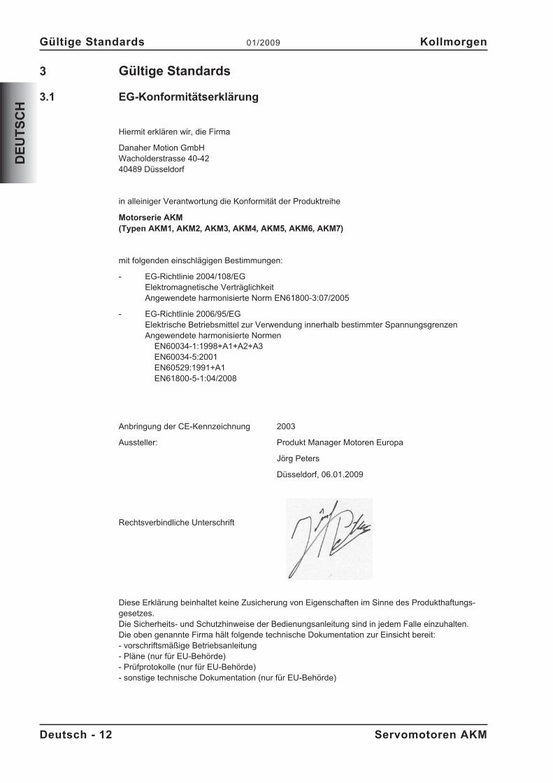
Aussteller: Produkt Manager Motoren Europa
Jörg Peters
Düsseldorf, 06.01.2009
Rechtsverbindliche Unterschrift
Diese Erklärung beinhaltet keine Zusicherung von Eigenschaften im Sinne des Produkthaftungs-gesetzes.Die Sicherheits- und Schutzhinweise der Bedienungsanleitung sind in jedem Falle einzuhalten.Die oben genannte Firma hält folgende technische Dokumentation zur Einsicht bereit:- vorschriftsmäßige Betriebsanleitung- Pläne (nur für EU-Behörde)- Prüfprotokolle (nur für EU-Behörde)- sonstige technische Dokumentation (nur für EU-Behörde)
Deutsch - 12 Servomotoren AKM
Gültige Standards 01/2009 Kollmorgen
DE
UT
SC
H
4 Handhabung
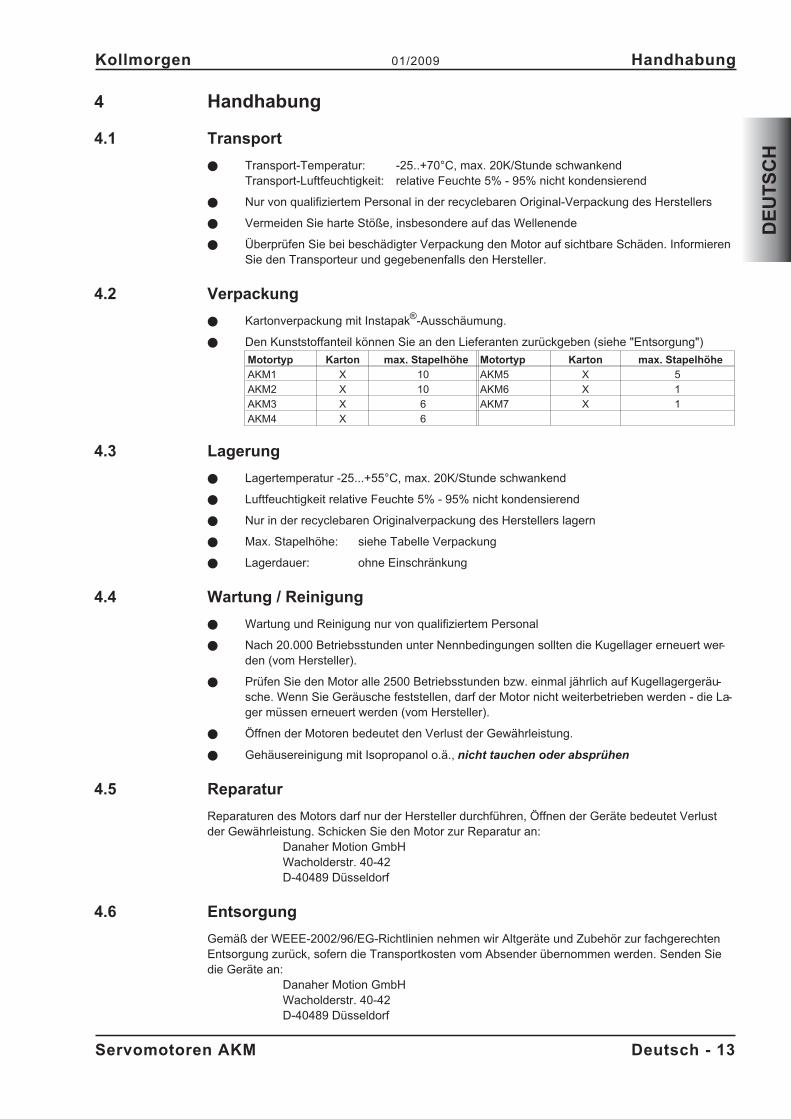
4.1 Transport
� Transport-Temperatur: -25..+70°C, max. 20K/Stunde schwankendTransport-Luftfeuchtigkeit: relative Feuchte 5% - 95% nicht kondensierend
� Nur von qualifiziertem Personal in der recyclebaren Original-Verpackung des Herstellers
� Vermeiden Sie harte Stöße, insbesondere auf das Wellenende
� Überprüfen Sie bei beschädigter Verpackung den Motor auf sichtbare Schäden. InformierenSie den Transporteur und gegebenenfalls den Hersteller.
4.2 Verpackung
� Kartonverpackung mit Instapak®-Ausschäumung.
� Den Kunststoffanteil können Sie an den Lieferanten zurückgeben (siehe "Entsorgung")
Motortyp Karton max. Stapelhöhe Motortyp Karton max. Stapelhöhe
AKM1 X 10 AKM5 X 5
AKM2 X 10 AKM6 X 1
AKM3 X 6 AKM7 X 1
AKM4 X 6
4.3 Lagerung
� Lagertemperatur -25...+55°C, max. 20K/Stunde schwankend
� Luftfeuchtigkeit relative Feuchte 5% - 95% nicht kondensierend
� Nur in der recyclebaren Originalverpackung des Herstellers lagern
� Max. Stapelhöhe: siehe Tabelle Verpackung
� Lagerdauer: ohne Einschränkung
4.4 Wartung / Reinigung
� Wartung und Reinigung nur von qualifiziertem Personal
� Nach 20.000 Betriebsstunden unter Nennbedingungen sollten die Kugellager erneuert wer-den (vom Hersteller).
� Prüfen Sie den Motor alle 2500 Betriebsstunden bzw. einmal jährlich auf Kugellagergeräu-sche. Wenn Sie Geräusche feststellen, darf der Motor nicht weiterbetrieben werden - die La-ger müssen erneuert werden (vom Hersteller).
� Öffnen der Motoren bedeutet den Verlust der Gewährleistung.
� Gehäusereinigung mit Isopropanol o.ä., nicht tauchen oder absprühen
4.5 Reparatur
Reparaturen des Motors darf nur der Hersteller durchführen, Öffnen der Geräte bedeutet Verlustder Gewährleistung. Schicken Sie den Motor zur Reparatur an:
Danaher Motion GmbHWacholderstr. 40-42D-40489 Düsseldorf
4.6 Entsorgung
Gemäß der WEEE-2002/96/EG-Richtlinien nehmen wir Altgeräte und Zubehör zur fachgerechtenEntsorgung zurück, sofern die Transportkosten vom Absender übernommen werden. Senden Siedie Geräte an:
Danaher Motion GmbHWacholderstr. 40-42D-40489 Düsseldorf
Servomotoren AKM Deutsch - 13
Kollmorgen 01/2009 Handhabung
DE
UT
SC
H
5 Produktidentifizierung
5.1 Lieferumfang
Sie erhalten einen Karton mit Instapak®-Ausschäumung. Enthalten ist:
� Motor der Serie AKM
� Produkthandbuch gedruckt, mehrsprachig
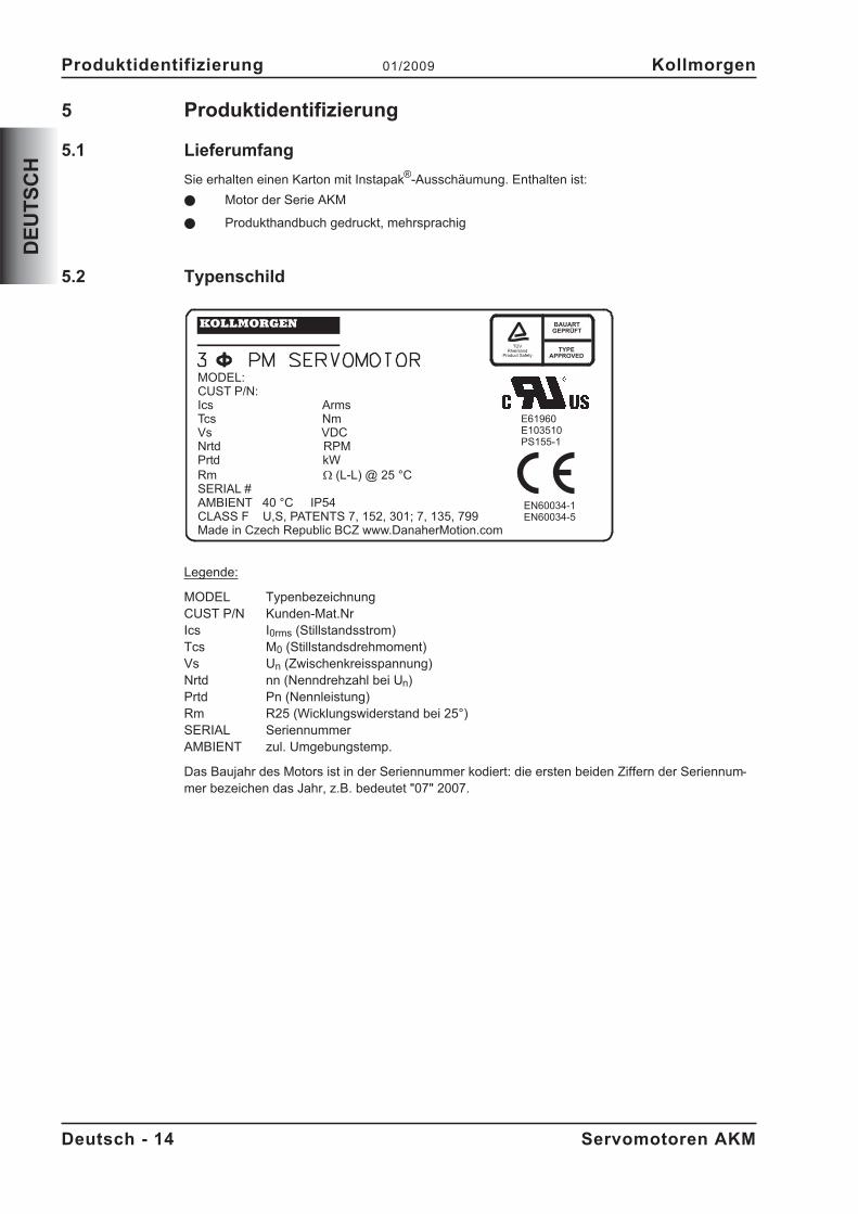
5.2 Typenschild
Legende:
MODEL TypenbezeichnungCUST P/N Kunden-Mat.NrIcs I0rms (Stillstandsstrom)Tcs M0 (Stillstandsdrehmoment)Vs Un (Zwischenkreisspannung)Nrtd nn (Nenndrehzahl bei Un)Prtd Pn (Nennleistung)Rm R25 (Wicklungswiderstand bei 25°)SERIAL SeriennummerAMBIENT zul. Umgebungstemp.
Das Baujahr des Motors ist in der Seriennummer kodiert: die ersten beiden Ziffern der Seriennum-mer bezeichen das Jahr, z.B. bedeutet "07" 2007.
Deutsch - 14 Servomotoren AKM
Produktidentifizierung 01/2009 Kollmorgen
DE
UT
SC
H
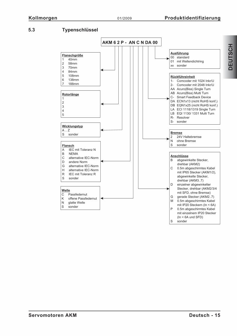
5.3 Typenschlüssel
Servomotoren AKM Deutsch - 15
Kollmorgen 01/2009 Produktidentifizierung
DE
UT
SC
H
Flanschgröße1 40mm2 58mm3 70mm4 84mm5 108mm6 138mm7 188mm
FlanschA IEC mit Toleranz NB NEMAC alternative IEC-NormD andere NormG alternative IEC-NormH alternative IEC-NormR IEC mit Toleranz RS sonder
Rotorlänge12345
WicklungstypA .. ZS sonder
AnschlüsseB abgewinkelte Stecker,
drehbar (AKM2)C 0.5m abgeschirmtes Kabel
mit IP65 Stecker (AKM1/2),abgewinkelte Stecker,drehbar (AKM3..7)
D einzelner abgewinkelterStecker, drehbar (AKM2/3/4mit SFD, ohne Bremse)
G gerade Stecker (AKM2..7)M 0.5m abgeschirmtes Kabel
mit IP20 Steckern (In < 6A)P 0.5m abgeschirmtes Kabel
mit einzelnem IP20 Stecker(In < 6A und SFD)
S sonder
Bremse2 24V HaltebremseN ohne BremseS sonder
Rückführeinheit1- Comcoder mit 1024 Inkr/U2- Comcoder mit 2048 Inkr/UAA Acuro(Biss) Single TurnAB Acuro(Biss) Multi TurnC- Smart Feedback DeviceDA ECN1x13 (nicht RoHS konf.)DB EQN1x25 (nicht RoHS konf.)LA ECI 1118/1319 Single TurnLB EQI 1130/ 1331 Multi TurnR- ResolverS- sonder
Ausführung00 standard01 mit Wellendichtringxx sonder
WelleC PassfedernutK offene PassfedernutN glatte WelleS sonder
AKM 6 2 P - AN C N DA 00
6 Technische Beschreibung
6.1 Allgemeine technische Daten
Umgebungstemperatur 5...+40°C bei Aufstellhöhe bis 1000m über NN(bei Nenndaten) Sprechen Sie bei Umgebungstemperaturen über 40°C
und bei gekapseltem Einbau der Motoren unbedingt mitunserer Applikationsabteilung.
Zulässige Luftfeuchte 95% relative Feuchte, nicht betauend(bei Nenndaten)
Leistungsreduzierung 1%/K im Bereich 40°C...50°C bis 1000m über NN(Ströme und Momente) Bei Aufstellhöhen über 1000m über NN und 40°C
6% bei 2000m über NN17% bei 3000m über NN30% bei 4000m über NN55% bei 5000m über NN
Keine Leistungsreduzierung bei Aufstellhöhen über1000m über NN und Temperaturreduzierungum 10K / 1000m
Kugellager-Lebensdauer � 20.000 Betriebsstunden
6.2 Standardausrüstung
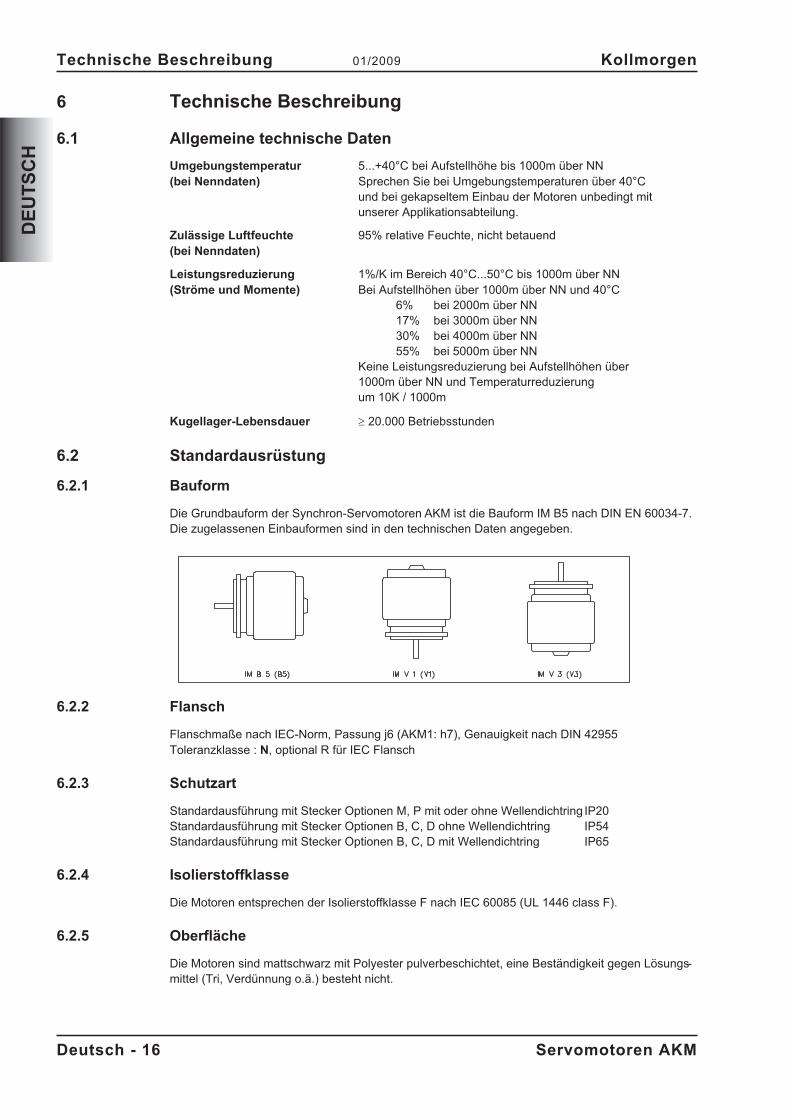
6.2.1 Bauform
Die Grundbauform der Synchron-Servomotoren AKM ist die Bauform IM B5 nach DIN EN 60034-7.Die zugelassenen Einbauformen sind in den technischen Daten angegeben.
6.2.2 Flansch
Flanschmaße nach IEC-Norm, Passung j6 (AKM1: h7), Genauigkeit nach DIN 42955Toleranzklasse : N, optional R für IEC Flansch
6.2.3 Schutzart
Standardausführung mit Stecker Optionen M, P mit oder ohne Wellendichtring IP20Standardausführung mit Stecker Optionen B, C, D ohne Wellendichtring IP54Standardausführung mit Stecker Optionen B, C, D mit Wellendichtring IP65
6.2.4 Isolierstoffklasse
Die Motoren entsprechen der Isolierstoffklasse F nach IEC 60085 (UL 1446 class F).
6.2.5 Oberfläche
Die Motoren sind mattschwarz mit Polyester pulverbeschichtet, eine Beständigkeit gegen Lösungs-mittel (Tri, Verdünnung o.ä.) besteht nicht.
Deutsch - 16 Servomotoren AKM
Technische Beschreibung 01/2009 Kollmorgen
DE
UT
SC
H
6.2.6 Wellenende A-Seite
Die Kraftübertragung erfolgt über das zylindrische Wellenende A, Passung k6 (AKM1: h7) nach DIN748 mit Anzugsgewinde aber ohne Passfedernut. Für die Lebensdauer der Lager sind 20.000Betriebsstunden zugrunde gelegt.
RadialkraftTreiben die Motoren über Ritzel oder Zahnriemen an, so treten hohe Radialkräfte auf.Die zugelassenen Werte am Wellenende abhängig von der Drehzahl entnehmen Sie den Diagram-men im Anhang. Die zugelassenen Maximalwerte finden Sie in den technischen Daten. Bei Kraftan-griff an der Mitte des freien Wellenendes kann FR 10% größer sein.
AxialkraftBei der Montage von Ritzel oder Riemenscheiben auf die Welle und bei Betrieb von z.B. Winkelge-trieben treten Axialkräfte auf. Die zugelassenen Maximalwerte finden Sie in den technischen Daten.
KupplungAls ideale spielfreie Kupplungselemente haben sich doppelkonische Spannzangen eventuell in Ver-bindung mit Metallbalg-Kupplungen bewährt.
6.2.7 Schutzeinrichtung
In der Standardausführung ist jeder Motor mit einem potentialfreien PTC ausgestattet. Der Schalt-
punkt liegt bei 155°C � 5%. Schutz gegen kurzzeitige, sehr hohe Überlastung bietet der PTC nicht.Der PTC ist bei Verwendung unserer vorkonfektionierten Resolverleitung in das Überwachungssys-tem der digitalen Servoverstärker integriert.
6.2.8 Schwinggüte
Die Motoren sind in Schwinggüte A nach EN 60034-14 ausgeführt. Das bedeutet für einen Dreh-zahlbereich von 600-3600 U/min und einer Achshöhe zwischen 56-132mm eine zul.Schwingstärke von 1,6mm/s als Effektivwert.
Drehzahl [U/min] max. rel. Schwingweg [µm] max. Run-out [µm]
<= 1800 90 23
> 1800 65 16
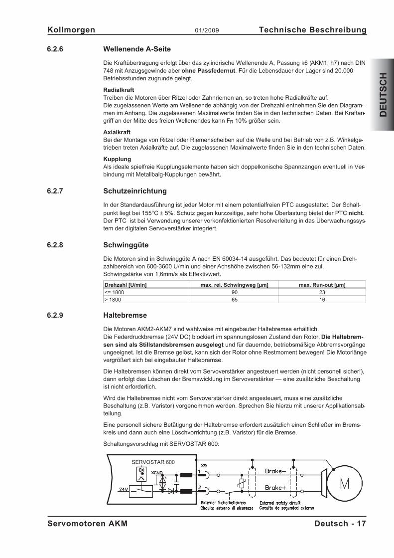
6.2.9 Haltebremse
Die Motoren AKM2-AKM7 sind wahlweise mit eingebauter Haltebremse erhältlich.Die Federdruckbremse (24V DC) blockiert im spannungslosen Zustand den Rotor. Die Haltebrem-sen sind als Stillstandsbremsen ausgelegt und für dauernde, betriebsmäßige Abbremsvorgängeungeeignet. Ist die Bremse gelöst, kann sich der Rotor ohne Restmoment bewegen! Die Motorlängevergrößert sich bei eingebauter Haltebremse.
Die Haltebremsen können direkt vom Servoverstärker angesteuert werden (nicht personell sicher!),dann erfolgt das Löschen der Bremswicklung im Servoverstärker — eine zusätzliche Beschaltungist nicht erforderlich.
Wird die Haltebremse nicht vom Servoverstärker direkt angesteuert, muss eine zusätzlicheBeschaltung (z.B. Varistor) vorgenommen werden. Sprechen Sie hierzu mit unserer Applikationsab-teilung.
Eine personell sichere Betätigung der Haltebremse erfordert zusätzlich einen Schließer im Brems-kreis und dann auch eine Löschvorrichtung (z.B. Varistor) für die Bremse.
Schaltungsvorschlag mit SERVOSTAR 600:
Servomotoren AKM Deutsch - 17
Kollmorgen 01/2009 Technische Beschreibung
DE
UT
SC
H
SERVOSTAR 600
7 Mechanische Installation
7.1 Wichtige Hinweise
Nur Fachleute mit Maschinenbau-Kenntnissen dürfen den Motor montieren. Maßzeichnun-gen finden Sie im Anhang.
� Schützen Sie die Motoren vor unzulässiger Beanspruchung.Insbesondere dürfen bei Transport und Handhabung keine Bauelemente verbogen und /oder Isolationsabstände verändert werden
� Der Einbauort muss frei von leitfähigen und aggressiven Stoffen sein.Beachten Sie bei V3-Montage (Wellenende nach oben), dass keine Flüssigkeit in die Lagereindringen darf. Bei gekapseltem Einbau sollten Sie zunächst mit unserer Applikationsabtei-lung Rücksprache nehmen.
� Stellen Sie die ungehinderte Belüftung der Motoren sicher und beachten Sie die zulässigeUmgebungs- und Flanschtemperatur. Bei Umgebungstemperaturen über 40°C sollten Siezunächst mit unserer Applikationsabteilung Rücksprache nehmen.
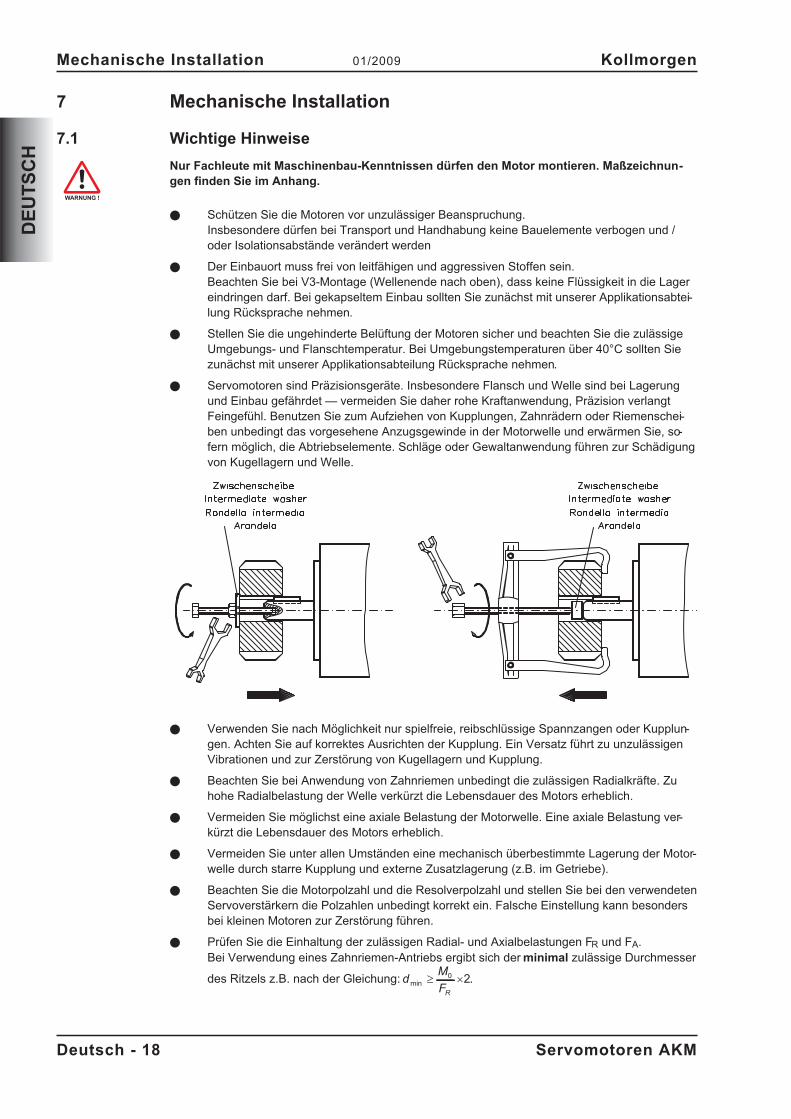
� Servomotoren sind Präzisionsgeräte. Insbesondere Flansch und Welle sind bei Lagerungund Einbau gefährdet — vermeiden Sie daher rohe Kraftanwendung, Präzision verlangtFeingefühl. Benutzen Sie zum Aufziehen von Kupplungen, Zahnrädern oder Riemenschei-ben unbedingt das vorgesehene Anzugsgewinde in der Motorwelle und erwärmen Sie, so-fern möglich, die Abtriebselemente. Schläge oder Gewaltanwendung führen zur Schädigungvon Kugellagern und Welle.
� Verwenden Sie nach Möglichkeit nur spielfreie, reibschlüssige Spannzangen oder Kupplun-gen. Achten Sie auf korrektes Ausrichten der Kupplung. Ein Versatz führt zu unzulässigenVibrationen und zur Zerstörung von Kugellagern und Kupplung.
� Beachten Sie bei Anwendung von Zahnriemen unbedingt die zulässigen Radialkräfte. Zuhohe Radialbelastung der Welle verkürzt die Lebensdauer des Motors erheblich.
� Vermeiden Sie möglichst eine axiale Belastung der Motorwelle. Eine axiale Belastung ver-kürzt die Lebensdauer des Motors erheblich.
� Vermeiden Sie unter allen Umständen eine mechanisch überbestimmte Lagerung der Motor-welle durch starre Kupplung und externe Zusatzlagerung (z.B. im Getriebe).
� Beachten Sie die Motorpolzahl und die Resolverpolzahl und stellen Sie bei den verwendetenServoverstärkern die Polzahlen unbedingt korrekt ein. Falsche Einstellung kann besondersbei kleinen Motoren zur Zerstörung führen.
� Prüfen Sie die Einhaltung der zulässigen Radial- und Axialbelastungen FR und FA.Bei Verwendung eines Zahnriemen-Antriebs ergibt sich der minimal zulässige Durchmesser
des Ritzels z.B. nach der Gleichung: dM
FR
min � �0 2.
Deutsch - 18 Servomotoren AKM
Mechanische Installation 01/2009 Kollmorgen
DE
UT
SC
H
8 Elektrische Installation
8.1 Sicherheitshinweise
Nur Fachleute mit elektrotechnischer Ausbildung dürfen den Motor verdrahten. Anschluss-pläne finden Sie im Anhang.
Montieren und verdrahten Sie die Motoren immer im spannungsfreien Zustand, d.h. keineder Betriebsspannungen eines anzuschließenden Gerätes darf eingeschaltet sein.Sorgen Sie für eine sichere Freischaltung des Schaltschrankes (Sperre, Warnschilder etc.).Erst bei der Inbetriebnahme werden die einzelnen Spannungen eingeschaltet.
Lösen Sie die elektrischen Anschlüsse der Motoren nie unter Spannung.Restladungen in den Kondensatoren des Servoverstärkers können auch bis zu 5 Minutennach Abschalten der Netzspannung gefährliche Werte aufweisen.Messen Sie die Spannung im Zwischenkreis und warten Sie, bis die Spannung unter 40Vabgesunken ist. Steuer- und Leistungsanschlüsse können Spannung führen, auch wennsich der Motor nicht dreht.
Das Masse-Zeichen�, das Sie in allen Anschlussplänen finden, deutet an, dass Sie füreine möglichst großflächige, elektrisch leitende Verbindung zwischen dem gekennzeichne-ten Gerät und der Montageplatte in Ihrem Schaltschrank sorgen müssen. Diese Verbindungsoll die Ableitung von HF-Störungen ermöglichen und ist nicht zu verwechseln mit demPE-Zeichen (Schutzmaßnahme nach EN 60204).Beachten Sie auch die Hinweise in den Anschlussplänen im Produkthandbuch des verwen-deten Servoverstärkers.
8.2 Leitfaden für die elektrische Installation
� Prüfen Sie die Zuordnung von Servoverstärker und Motor. Vergleichen Sie Nennspannungund Nennstrom der Geräte. Führen Sie die Verdrahtung nach dem Anschlussbild im Pro-dukthandbuch des Servoverstärkers aus. Die Anschlüsse des Motors sind im Anhang darge-stellt.
� Achten Sie auf einwandfreie Erdung von Servoverstärker und Motor. EMV-gerechte Abschir-mung und Erdung siehe Produkthandbuch des verwendeten Servoverstärkers. Erden SieMontageplatte und Motorgehäuse.
� Verlegen Sie Leistungs- und Steuerkabel möglichst getrennt (Abstand > 20 cm). Die elektro-magnetische Verträglichkeit des Systems wird so verbessert. Bei Verwendung eines Motor-leistungskabels mit integrierten Bremssteueradern müssen die Bremssteueradern abge-schirmt sein. Der Schirm muss beidseitig aufgelegt werden (siehe Produkthandbuch desServoverstärkers).
� Verdrahtung:— Leistungs- und Steuerkabel möglichst getrennt verlegen— Resolver bzw. Encoder anschließen— Motorleitungen anschließen Motordrossel nahe am Servoverstärker— Abschirmungen beidseitig auf Schirmklemmen bzw. EMV-Stecker— Motor-Haltebremse anschließen— Abschirmung beidseitig auflegen
� Verlegen Sie sämtliche starkstromführenden Leitungen in ausreichendem Querschnitt nachEN 60204. Die empfohlenen Querschnitte finden Sie in den technischen Daten.Abhängig vom Typ des verwendeten Servoverstärkers muss bei langen Motorleitung(> 25m) eine Motordrossel (3YL) in die Motorleitung geschaltet werden (siehe Pro-dukthandbuch des Servoverstärkers und Zubehörhandbuch).
� Legen Sie Abschirmungen großflächig (niederohmig) über metallisierte Steckergehäusebzw. EMV-gerechte Kabelverschraubungen auf.
Servomotoren AKM Deutsch - 19
Kollmorgen 01/2009 Elektrische Installation
DE
UT
SC
H
8.3 Anschluss der Motoren mit vorkonfektionierten Kabeln
� Führen Sie die Verdrahtung gemäß den geltenden Vorschriften und Normen aus.Anschlusspläne finden Sie im Anhang.
� Verwenden Sie für Leistungs- und Rückführanschluss ausschließlich unsere vorkon-fektionierten, abgeschirmten Leitungen.
� Legen Sie die Abschirmungen entsprechend den Anschlussbildern im Produkthand-buch des Servoverstärkers auf.
� Nicht korrekt aufgelegte Abschirmungen führen unweigerlich zu EMV-Störungen.
� Die maximale Leitungslänge ist im Produkthandbuch des verwendeten Servoverstär-kers definiert.
Anforderungen an das Leitungsmaterial:
KapazitätMotorleitung: kleiner als 150 pF/mFeedback-Leitung: kleiner als 120 pF/m
Techn. Daten unserer konfektionierten Leitungen finden Sie im Zubehörhandbuch.
Deutsch - 20 Servomotoren AKM
Elektrische Installation 01/2009 Kollmorgen
DE
UT
SC
H
9 Inbetriebnahme
9.1 Wichtige Hinweise
Nur Fachleute mit weitreichenden Kenntnissen in den Bereichen Elektrotechnik /Antriebs-technik dürfen die Antriebseinheit Servoverstärker/Motor in Betrieb nehmen.
Prüfen Sie, ob alle spannungsführenden Anschlussteile gegen Berührung sicher geschütztsind. Es treten lebensgefährliche Spannungen bis zu 900V auf.
Lösen Sie die elektrischen Anschlüsse der Motoren nie unter Spannung. Restladungen inKondensatoren der Servoverstärker können bis zu 5 Minuten nach Abschalten der Netzspan-nung gefährliche Werte aufweisen.
Die Oberflächentemperatur des Motors kann im Betrieb 100°C überschreiten. Prüfen (mes-sen) Sie die Temperatur des Motors. Warten Sie, bis der Motor auf 40°C abgekühlt ist, bevorSie ihn berühren.
Stellen Sie sicher, dass auch bei ungewollter Bewegung des Antriebs keine maschinelleoder personelle Gefährdung eintreten kann.
9.2 Leitfaden für die Inbetriebnahme
Das Vorgehen bei der Inbetriebnahme wird exemplarisch beschrieben.Je nach Einsatz der Geräte kann auch ein anderes Vorgehen sinnvoll und erforderlich sein.
� Prüfen Sie Montage und Ausrichtung des Motors.
� Prüfen Sie die Abtriebselemente (Kupplung, Getriebe, Riemenscheibe) auf festen Sitz undkorrekte Einstellung (zulässige Radial- und Axialkräfte beachten).
� Prüfen Sie die Verdrahtung und Anschlüsse an Motor und Servoverstärker. Achten Sie aufordnungsgemäße Erdung.
� Prüfen Sie die Funktion der Haltebremse, sofern vorhanden. (24V anlegen, Bremse musslüften).
� Prüfen Sie, ob der Rotor des Motors sich frei drehen lässt (eventuell vorhandene Bremsevorher lüften). Achten Sie auf Schleifgeräusche.
� Prüfen Sie, ob alle erforderlichen Berührungsschutz-Maßnahmen für bewegte undspannungsführende Teile getroffen wurden.
� Führen Sie weitere für Ihre Anlage spezifischen und notwendigen Prüfungen durch.
� Nehmen Sie nun entsprechend der Inbetriebnahmeanweisung des Servoverstärkers den An-trieb in Betrieb.
� Nehmen Sie bei Mehrachs-Systemen jede Antriebseinheit Servoverstärker/Motor einzeln inBetrieb.
Servomotoren AKM Deutsch - 21
Kollmorgen 01/2009 Inbetriebnahme
DE
UT
SC
H
9.3 Beseitigen von Störungen
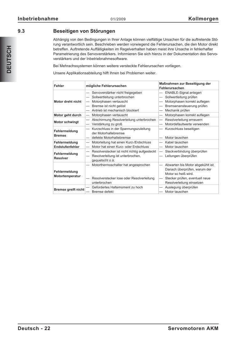
Abhängig von den Bedingungen in Ihrer Anlage können vielfältige Ursachen für die auftretende Stö-rung verantwortlich sein. Beschrieben werden vorwiegend die Fehlerursachen, die den Motor direktbetreffen. Auftretende Auffälligkeiten im Regelverhalten haben meist ihre Ursache in fehlerhafterParametrierung des Servoverstärkers. Informieren Sie sich hierzu in der Dokumentation des Servo-verstärkers und der Inbetriebnahmesoftware.
Bei Mehrachssystemen können weitere versteckte Fehlerursachen vorliegen.
Unsere Applikationsabteilung hilft Ihnen bei Problemen weiter.
Fehler mögliche FehlerursachenMaßnahmen zur Beseitigung derFehlerursachen
Motor dreht nicht
— Servoverstärker nicht freigegeben— Sollwertleitung unterbrochen— Motorphasen vertauscht— Bremse ist nicht gelöst— Antrieb ist mechanisch blockiert
— ENABLE-Signal anlegen— Sollwertleitung prüfen— Motorphasen korrekt auflegen— Bremsenansteuerung prüfen— Mechanik prüfen
Motor geht durch — Motorphasen vertauscht — Motorphasen korrekt auflegen
Motor schwingt— Abschirmung Resolverleitung unterbrochen— Verstärkung zu groß
— Resolverleitung erneuern— Motordefaultwerte verwenden
FehlermeldungBremse
— Kurzschluss in der Spannungszuleitungder Motorhaltebremse
— defekte Motorhaltebremse
— Kurzschluss beseitigen
— Motor tauschen
FehlermeldungEndstufenfehler
— Motorleitung hat einen Kurz-/Erdschluss— Motor hat einen Kurz- oder Erdschluss
— Kabel tauschen— Motor tauschen
FehlermeldungResolver
— Resolverstecker ist nicht richtig aufgesteckt— Resolverleitung ist unterbrochen,
gequetscht o.ä.
— Steckverbindung überprüfen— Leitungen überprüfen
FehlermeldungMotortemperatur
— Motorthermoschalter hat angesprochen
— Resolverstecker lose oder Resolverleitungunterbrochen
— Abwarten bis Motor abgekühlt ist.Danach überprüfen, warum derMotor so heiß wird.
— Stecker prüfen, eventuell neueResolverleitung einsetzen
Bremse greift nicht— Gefordertes Haltemoment zu hoch— Bremse defekt
— Auslegung überprüfen— Motor tauschen
Deutsch - 22 Servomotoren AKM
Inbetriebnahme 01/2009 Kollmorgen
DE
UT
SC
H
10 Technische Daten
Alle Angaben bei 40°C Umgebungstemperatur und 100K Wicklungsübertemperatur.Die Daten können eine Toleranz von +/- 10% aufweisen.
10.1 Begriffsdefinitionen
Stillstandsdrehmoment M0 [Nm]Das Stillstandsdrehmoment kann bei Drehzahl 0<n<100 min-1 und Nenn-Umgebungsbedingungenunbegrenzt lange abgegeben werden.
Nenndrehmoment Mn [Nm]Das Nenndrehmoment wird abgegeben, wenn der Motor bei Nenndrehzahl Nennstrom aufnimmt.Das Nenndrehmoment kann im Dauerbetrieb (S1) bei Nenndrehzahl unbegrenzt lange abgegebenwerden.
Stillstandsstrom I0rms [A]Der Stillstandsstrom ist der Sinus-Effektiv-Stromwert, den der Motor bei 0<n<100 min-1 aufnimmt,um das Stillstandsdrehmoment abgeben zu können.
Spitzenstrom (Impulsstrom) I0max [A]Der Spitzenstrom (Sinus-Effektivwert) entspricht ca. dem 4-fachen Stillstandsstrom.Der Spitzenstrom des verwendeten Servoverstärkers muss kleiner sein.
Drehmomentkonstante KTrms [Nm/A]Die Drehmomentkonstante gibt an, wie viel Drehmoment in Nm der Motor mit 1A Sinus-Effektiv-strom erzeugt. Es gilt M=I x KT (bis maximal I = 2 x I0)
Spannungskonstante KErms [mVmin]Die Spannungskonstante gibt die auf 1000U/min bezogene induzierte Motor EMK als Sinus-Effek-tivwert zwischen zwei Klemmen an.
Rotorträgheitsmoment J [kgcm²]Die Konstante J ist ein Maß für das Beschleunigungsvermögen des Motors. Mit I0 ergibt sich z.B.die Beschleunigungszeit tb von 0 bis 3000 min-1 zu :
t sM s
m
cmJ
b[ ] �
�
��
��
3000 2
60 100
2
4 2
�mit M0 in Nm und J in kgcm²
Thermische Zeitkonstante tth [min]Die Konstante tth gibt die Erwärmungszeit des kalten Motors bei Belastung mit I0 bis zumErreichen von 0,63 x 100 Kelvin Übertemperatur an.Bei Belastung mit Spitzenstrom erfolgt die Erwärmung in wesentlich kürzerer Zeit.
Lüftverzögerungszeit tBRH [ms] / Einfallverzögerungszeit tBRL [ms] der BremseDie Konstanten geben die Reaktionszeiten der Haltebremse bei Betrieb mit Nennspannung am Ser-voverstärker an.
UN
Netznennspannung
Un
Zwischenkreisspannung. U Un N
� �2
Servomotoren AKM Deutsch - 23
Kollmorgen 01/2009 Technische Daten
DE
UT
SC
H
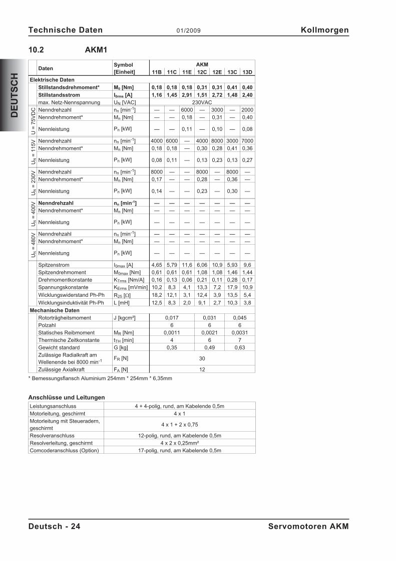
10.2 AKM1
DatenSymbol[Einheit]
AKM
11B 11C 11E 12C 12E 13C 13D
Elektrische Daten
Stillstandsdrehmoment* M0 [Nm] 0,18 0,18 0,18 0,31 0,31 0,41 0,40
Stillstandsstrom I0rms [A] 1,16 1,45 2,91 1,51 2,72 1,48 2,40
max. Netz-Nennspannung UN [VAC] 230VAC
U=
75
VD
C Nenndrehzahl nn [min-1] — — 6000 — 3000 — 2000
Nenndrehmoment* Mn [Nm] — — 0,18 — 0,31 — 0,40
Nennleistung Pn [kW] — — 0,11 — 0,10 — 0,08
UN
=1
15
V Nenndrehzahl nn [min-1] 4000 6000 — 4000 8000 3000 7000
Nenndrehmoment* Mn [Nm] 0,18 0,18 — 0,30 0,28 0,41 0,36
Nennleistung Pn [kW] 0,08 0,11 — 0,13 0,23 0,13 0,27
UN
=2
30
V Nenndrehzahl nn [min-1] 8000 — — 8000 — 8000 —
Nenndrehmoment* Mn [Nm] 0,17 — — 0,28 — 0,36 —
Nennleistung Pn [kW] 0,14 — — 0,23 — 0,30 —
UN
=4
00
V Nenndrehzahl nn [min-1] — — — — — — —
Nenndrehmoment* Mn [Nm] — — — — — — —
Nennleistung Pn [kW] — — — — — — —
UN
=4
80
V Nenndrehzahl nn [min-1] — — — — — — —
Nenndrehmoment* Mn [Nm] — — — — — — —
Nennleistung Pn [kW] — — — — — — —
Spitzenstrom I0max [A] 4,65 5,79 11,6 6,06 10,9 5,93 9,6
Spitzendrehmoment M0max [Nm] 0,61 0,61 0,61 1,08 1,08 1,46 1,44
Drehmomentkonstante KTrms [Nm/A] 0,16 0,13 0,06 0,21 0,11 0,28 0,17
Spannungskonstante KErms [mVmin] 10,2 8,3 4,1 13,3 7,2 17,9 10,9
Wicklungswiderstand Ph-Ph R25 [] 18,2 12,1 3,1 12,4 3,9 13,5 5,4
Wicklungsinduktivität Ph-Ph L [mH] 12,5 8,3 2,0 9,1 2,7 10,3 3,8
Mechanische Daten
Rotorträgheitsmoment J [kgcm²] 0,017 0,031 0,045
Polzahl 6 6 6
Statisches Reibmoment MR [Nm] 0,0011 0,0021 0,0031
Thermische Zeitkonstante tTH [min] 4 6 7
Gewicht standard G [kg] 0,35 0,49 0,63
Zulässige Radialkraft amWellenende bei 8000 min-1 FR [N] 30
Zulässige Axialkraft FA [N] 12
* Bemessungsflansch Aluminium 254mm * 254mm * 6,35mm
Anschlüsse und Leitungen
Leistungsanschluss 4 + 4-polig, rund, am Kabelende 0,5m
Motorleitung, geschirmt 4 x 1
Motorleitung mit Steueradern,geschirmt
4 x 1 + 2 x 0,75
Resolveranschluss 12-polig, rund, am Kabelende 0,5m
Resolverleitung, geschirmt 4 x 2 x 0,25mm²
Comcoderanschluss (Option) 17-polig, rund, am Kabelende 0,5m
Deutsch - 24 Servomotoren AKM
Technische Daten 01/2009 Kollmorgen
DE
UT
SC
H
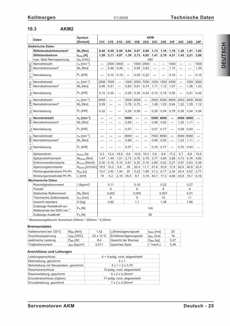
10.3 AKM2
DatenSymbol[Einheit]
AKM
21C 21E 21G 22C 22E 22G 23C 23D 23F 24C 24D 24F
Elektrische Daten
Stillstandsdrehmoment* M0 [Nm] 0,48 0,50 0,50 0,84 0,87 0,88 1,13 1,16 1,18 1,38 1,41 1,42
Stillstandsstrom I0rms [A] 1,58 3,11 4,87 1,39 2,73 4,82 1,41 2,19 4,31 1,42 2,21 3,89
max. Netz-Nennspannung UN [VAC] 480
U=
75
VD
C Nenndrehzahl nn [min-1] — 2000 4000 — 1000 2500 — — 1500 — — 1000
Nenndrehmoment* Mn [Nm] — 0,48 0,46 — 0,85 0,83 — — 1,15 — — 1,39
Nennleistung Pn [kW] — 0,10 0,19 — 0,09 0,22 — — 0,18 — — 0,15
UN
=1
15
V Nenndrehzahl nn [min-1] 2500 7000 — 1000 3500 7000 1000 1500 4500 — 1500 3000
Nenndrehmoment* Mn [Nm] 0,46 0,41 — 0,83 0,81 0,74 1,11 1,12 1,07 — 1,36 1,33
Nennleistung Pn [kW] 0,12 0,30 — 0,09 0,30 0,54 0,12 0,18 0,50 — 0,21 0,42
UN
=2
30
V Nenndrehzahl nn [min-1] 8000 — — 3500 8000 — 2500 5000 8000 2000 4000 8000
Nenndrehmoment* Mn [Nm] 0,39 — — 0,78 0,70 — 1,08 1,03 0,94 1,32 1,29 1,12
Nennleistung Pn [kW] 0,32 — — 0,29 0,59 — 0,28 0,54 0,79 0,28 0,54 0,94
UN
=4
00
V Nenndrehzahl nn [min-1] — — — 8000 — — 5500 8000 — 4500 8000 —
Nenndrehmoment* Mn [Nm] — — — 0,68 — — 0,99 0,92 — 1,25 1,11 —
Nennleistung Pn [kW] — — — 0,57 — — 0,57 0,77 — 0,59 0,93 —
UN
=4
80
V Nenndrehzahl nn [min-1] — — — 8000 — — 7000 8000 — 5500 8000 —
Nenndrehmoment* Mn [Nm] — — — 0,68 — — 0,95 0,92 — 1,22 1,11 —
Nennleistung Pn [kW] — — — 0,57 — — 0,70 0,77 — 0,70 0,93 —
Spitzenstrom I0max [A] 6,3 12,4 19,5 5,6 10,9 19,3 5,6 8,8 17,2 5,7 8,8 15,6
Spitzendrehmoment M0max [Nm] 1,47 1,49 1,51 2,73 2,76 2,79 3,77 3,84 3,88 4,73 4,76 4,82
Drehmomentkonstante KTrms [Nm/A] 0,30 0,16 0,10 0,61 0,32 0,18 0,80 0,52 0,27 0,97 0,63 0,36
Spannungskonstante KErms [mVmin] 19,5 10,2 6,6 39 20,4 11,7 51,8 33,8 17,6 62,4 40,8 23,4
Wicklungswiderstand Ph-Ph R25 [] 13,0 3,42 1,44 20 5,22 1,69 21,2 8,77 2,34 20,4 9,02 2,77
Wicklungsinduktivität Ph-Ph L [mH] 19 5,2 2,18 35,5 9,7 3,19 40,7 17,3 4,68 43,8 18,7 6,16
Mechanische Daten
Rotorträgheitsmoment J [kgcm²] 0,11 0,16 0,22 0,27
Polzahl 6 6 6 6
Statisches Reibmoment MR [Nm] 0,002 0,005 0,007 0,01
Thermische Zeitkonstante tTH [min] 8 9 10 11
Gewicht standard G [kg] 0,82 1,1 1,38 1,66
Zulässige Radialkraft amWellenende bei 5000 min-1 FR [N] 145
Zulässige Axialkraft FA [N] 60
* Bemessungsflansch Aluminium 254mm * 254mm * 6,35mm
Bremsendaten
Haltemoment bei 120°C MBR [Nm] 1,42 Lüftverzögerungszeit tBRH [ms] 20
Anschlussspannung UBR [VDC] 24 ± 10 % Einfallverzögerungszeit tBRL [ms] 18
elektrische Leistung PBR [W] 8,4 Gewicht der Bremse GBR [kg] 0,27
Trägheitsmoment JBR [kgcm²] 0,011 typisches Spiel [ °mech.] 0,46
Anschlüsse und Leitungen
Leistungsanschluss 4 + 4-polig, rund, abgewinkelt
Motorleitung, geschirmt 4 x 1
Motorleitung mit Steueradern, geschirmt 4 x 1 + 2 x 0,75
Resolveranschluss 12-polig, rund, abgewinkelt
Resolverleitung, geschirmt 4 x 2 x 0,25mm²
Encoderanschluss (Option) 17-polig, rund, abgewinkelt
Encoderleitung, geschirmt 7 x 2 x 0,25mm²
Servomotoren AKM Deutsch - 25
Kollmorgen 01/2009 Technische Daten
DE
UT
SC
H
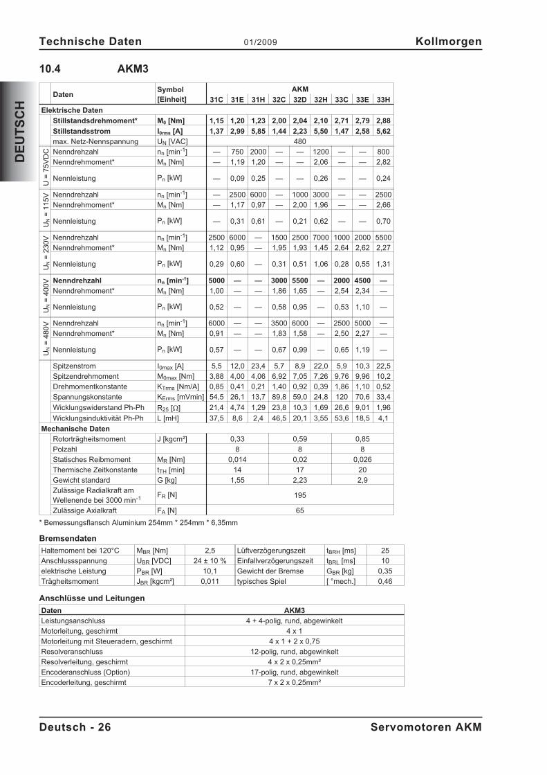
10.4 AKM3
DatenSymbol[Einheit]
AKM
31C 31E 31H 32C 32D 32H 33C 33E 33H
Elektrische Daten
Stillstandsdrehmoment* M0 [Nm] 1,15 1,20 1,23 2,00 2,04 2,10 2,71 2,79 2,88
Stillstandsstrom I0rms [A] 1,37 2,99 5,85 1,44 2,23 5,50 1,47 2,58 5,62
max. Netz-Nennspannung UN [VAC] 480
U=
75
VD
C Nenndrehzahl nn [min-1] — 750 2000 — — 1200 — — 800
Nenndrehmoment* Mn [Nm] — 1,19 1,20 — — 2,06 — — 2,82
Nennleistung Pn [kW] — 0,09 0,25 — — 0,26 — — 0,24
UN
=1
15
V Nenndrehzahl nn [min-1] — 2500 6000 — 1000 3000 — — 2500
Nenndrehmoment* Mn [Nm] — 1,17 0,97 — 2,00 1,96 — — 2,66
Nennleistung Pn [kW] — 0,31 0,61 — 0,21 0,62 — — 0,70
UN
=2
30
V Nenndrehzahl nn [min-1] 2500 6000 — 1500 2500 7000 1000 2000 5500
Nenndrehmoment* Mn [Nm] 1,12 0,95 — 1,95 1,93 1,45 2,64 2,62 2,27
Nennleistung Pn [kW] 0,29 0,60 — 0,31 0,51 1,06 0,28 0,55 1,31
UN
=4
00
V Nenndrehzahl nn [min-1] 5000 — — 3000 5500 — 2000 4500 —
Nenndrehmoment* Mn [Nm] 1,00 — — 1,86 1,65 — 2,54 2,34 —
Nennleistung Pn [kW] 0,52 — — 0,58 0,95 — 0,53 1,10 —
UN
=4
80
V Nenndrehzahl nn [min-1] 6000 — — 3500 6000 — 2500 5000 —
Nenndrehmoment* Mn [Nm] 0,91 — — 1,83 1,58 — 2,50 2,27 —
Nennleistung Pn [kW] 0,57 — — 0,67 0,99 — 0,65 1,19 —
Spitzenstrom I0max [A] 5,5 12,0 23,4 5,7 8,9 22,0 5,9 10,3 22,5
Spitzendrehmoment M0max [Nm] 3,88 4,00 4,06 6,92 7,05 7,26 9,76 9,96 10,2
Drehmomentkonstante KTrms [Nm/A] 0,85 0,41 0,21 1,40 0,92 0,39 1,86 1,10 0,52
Spannungskonstante KErms [mVmin] 54,5 26,1 13,7 89,8 59,0 24,8 120 70,6 33,4
Wicklungswiderstand Ph-Ph R25 [] 21,4 4,74 1,29 23,8 10,3 1,69 26,6 9,01 1,96
Wicklungsinduktivität Ph-Ph L [mH] 37,5 8,6 2,4 46,5 20,1 3,55 53,6 18,5 4,1
Mechanische Daten
Rotorträgheitsmoment J [kgcm²] 0,33 0,59 0,85
Polzahl 8 8 8
Statisches Reibmoment MR [Nm] 0,014 0,02 0,026
Thermische Zeitkonstante tTH [min] 14 17 20
Gewicht standard G [kg] 1,55 2,23 2,9
Zulässige Radialkraft amWellenende bei 3000 min-1 FR [N] 195
Zulässige Axialkraft FA [N] 65
* Bemessungsflansch Aluminium 254mm * 254mm * 6,35mm
Bremsendaten
Haltemoment bei 120°C MBR [Nm] 2,5 Lüftverzögerungszeit tBRH [ms] 25
Anschlussspannung UBR [VDC] 24 ± 10 % Einfallverzögerungszeit tBRL [ms] 10
elektrische Leistung PBR [W] 10,1 Gewicht der Bremse GBR [kg] 0,35
Trägheitsmoment JBR [kgcm²] 0,011 typisches Spiel [ °mech.] 0,46
Anschlüsse und Leitungen
Daten AKM3
Leistungsanschluss 4 + 4-polig, rund, abgewinkelt
Motorleitung, geschirmt 4 x 1
Motorleitung mit Steueradern, geschirmt 4 x 1 + 2 x 0,75
Resolveranschluss 12-polig, rund, abgewinkelt
Resolverleitung, geschirmt 4 x 2 x 0,25mm²
Encoderanschluss (Option) 17-polig, rund, abgewinkelt
Encoderleitung, geschirmt 7 x 2 x 0,25mm²
Deutsch - 26 Servomotoren AKM
Technische Daten 01/2009 Kollmorgen
DE
UT
SC
H
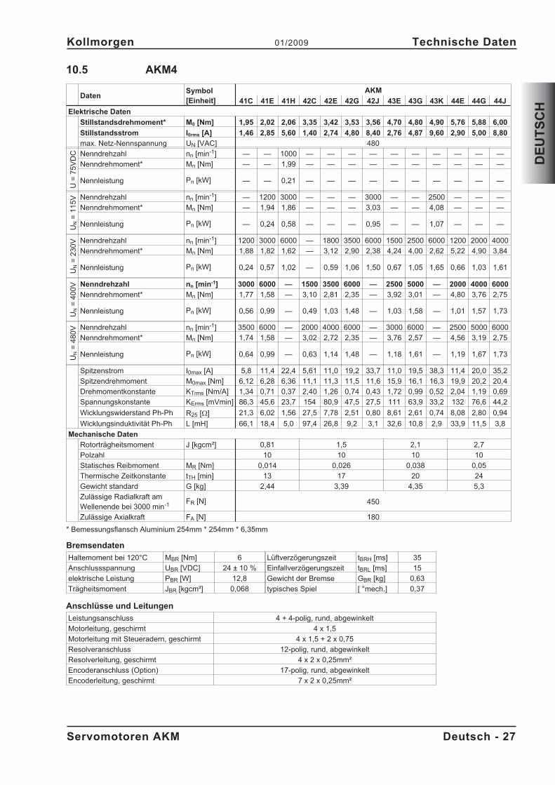
10.5 AKM4
DatenSymbol[Einheit]
AKM
41C 41E 41H 42C 42E 42G 42J 43E 43G 43K 44E 44G 44J
Elektrische Daten
Stillstandsdrehmoment* M0 [Nm] 1,95 2,02 2,06 3,35 3,42 3,53 3,56 4,70 4,80 4,90 5,76 5,88 6,00
Stillstandsstrom I0rms [A] 1,46 2,85 5,60 1,40 2,74 4,80 8,40 2,76 4,87 9,60 2,90 5,00 8,80
max. Netz-Nennspannung UN [VAC] 480
U=
75
VD
C Nenndrehzahl nn [min-1] — — 1000 — — — — — — — — — —
Nenndrehmoment* Mn [Nm] — — 1,99 — — — — — — — — — —
Nennleistung Pn [kW] — — 0,21 — — — — — — — — — —
UN
=1
15
V Nenndrehzahl nn [min-1] — 1200 3000 — — — 3000 — — 2500 — — —
Nenndrehmoment* Mn [Nm] — 1,94 1,86 — — — 3,03 — — 4,08 — — —
Nennleistung Pn [kW] — 0,24 0,58 — — — 0,95 — — 1,07 — — —
UN
=2
30
V Nenndrehzahl nn [min-1] 1200 3000 6000 — 1800 3500 6000 1500 2500 6000 1200 2000 4000
Nenndrehmoment* Mn [Nm] 1,88 1,82 1,62 — 3,12 2,90 2,38 4,24 4,00 2,62 5,22 4,90 3,84
Nennleistung Pn [kW] 0,24 0,57 1,02 — 0,59 1,06 1,50 0,67 1,05 1,65 0,66 1,03 1,61
UN
=4
00
V Nenndrehzahl nn [min-1] 3000 6000 — 1500 3500 6000 — 2500 5000 — 2000 4000 6000
Nenndrehmoment* Mn [Nm] 1,77 1,58 — 3,10 2,81 2,35 — 3,92 3,01 — 4,80 3,76 2,75
Nennleistung Pn [kW] 0,56 0,99 — 0,49 1,03 1,48 — 1,03 1,58 — 1,01 1,57 1,73
UN
=4
80
V Nenndrehzahl nn [min-1] 3500 6000 — 2000 4000 6000 — 3000 6000 — 2500 5000 6000
Nenndrehmoment* Mn [Nm] 1,74 1,58 — 3,02 2,72 2,35 — 3,76 2,57 — 4,56 3,19 2,75
Nennleistung Pn [kW] 0,64 0,99 — 0,63 1,14 1,48 — 1,18 1,61 — 1,19 1,67 1,73
Spitzenstrom I0max [A] 5,8 11,4 22,4 5,61 11,0 19,2 33,7 11,0 19,5 38,3 11,4 20,0 35,2
Spitzendrehmoment M0max [Nm] 6,12 6,28 6,36 11,1 11,3 11,5 11,6 15,9 16,1 16,3 19,9 20,2 20,4
Drehmomentkonstante KTrms [Nm/A] 1,34 0,71 0,37 2,40 1,26 0,74 0,43 1,72 0,99 0,52 2,04 1,19 0,69
Spannungskonstante KErms [mVmin] 86,3 45,6 23,7 154 80,9 47,5 27,5 111 63,9 33,2 132 76,6 44,2
Wicklungswiderstand Ph-Ph R25 [] 21,3 6,02 1,56 27,5 7,78 2,51 0,80 8,61 2,61 0,74 8,08 2,80 0,94
Wicklungsinduktivität Ph-Ph L [mH] 66,1 18,4 5,0 97,4 26,8 9,2 3,1 32,6 10,8 2,9 33,9 11,5 3,8
Mechanische Daten
Rotorträgheitsmoment J [kgcm²] 0,81 1,5 2,1 2,7
Polzahl 10 10 10 10
Statisches Reibmoment MR [Nm] 0,014 0,026 0,038 0,05
Thermische Zeitkonstante tTH [min] 13 17 20 24
Gewicht standard G [kg] 2,44 3,39 4,35 5,3
Zulässige Radialkraft amWellenende bei 3000 min-1 FR [N] 450
Zulässige Axialkraft FA [N] 180
* Bemessungsflansch Aluminium 254mm * 254mm * 6,35mm
Bremsendaten
Haltemoment bei 120°C MBR [Nm] 6 Lüftverzögerungszeit tBRH [ms] 35
Anschlussspannung UBR [VDC] 24 ± 10 % Einfallverzögerungszeit tBRL [ms] 15
elektrische Leistung PBR [W] 12,8 Gewicht der Bremse GBR [kg] 0,63
Trägheitsmoment JBR [kgcm²] 0,068 typisches Spiel [ °mech.] 0,37
Anschlüsse und Leitungen
Leistungsanschluss 4 + 4-polig, rund, abgewinkelt
Motorleitung, geschirmt 4 x 1,5
Motorleitung mit Steueradern, geschirmt 4 x 1,5 + 2 x 0,75
Resolveranschluss 12-polig, rund, abgewinkelt
Resolverleitung, geschirmt 4 x 2 x 0,25mm²
Encoderanschluss (Option) 17-polig, rund, abgewinkelt
Encoderleitung, geschirmt 7 x 2 x 0,25mm²
Servomotoren AKM Deutsch - 27
Kollmorgen 01/2009 Technische Daten
DE
UT
SC
H
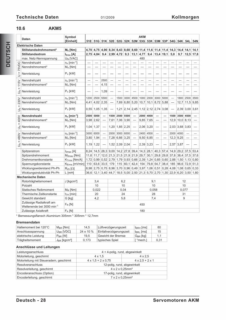
10.6 AKM5
DatenSymbol[Einheit]
AKM
51E 51G 51K 52E 52G 52K 52M 53G 53K 53M 53P 54G 54K 54L 54N
Elektrische Daten
Stillstandsdrehmoment* M0 [Nm] 4,70 4,75 4,90 8,34 8,43 8,60 8,60 11,4 11,6 11,4 11,4 14,3 14,4 14,1 14,1
Stillstandsstrom I0rms [A] 2,75 4,84 9,4 2,99 4,72 9,3 13,1 4,77 9,4 13,4 19,1 5,0 9,7 12,5 17,8
max. Netz-Nennspannung UN [VAC] 480
U=
75
VD
C Nenndrehzahl nn [min-1] — — — — — — — — — — — — — — —
Nenndrehmoment* Mn [Nm] — — — — — — — — — — — — — — —
Nennleistung Pn [kW] — — — — — — — — — — — — — — —
UN
=1
15
V Nenndrehzahl nn [min-1] — — 2500 — — — — — — — — — — — —
Nenndrehmoment* Mn [Nm] — — 4,15 — — — — — — — — — — — —
Nennleistung Pn [kW] — — 1,09 — — — — — — — — — — — —
UN
=2
30
V Nenndrehzahl nn [min-1] 1200 2500 5500 — 1500 3000 4500 1000 2000 3000 5000 — 1800 2500 3500
Nenndrehmoment* Mn [Nm] 4,41 4,02 2,35 — 7,69 6,80 5,20 10,7 10,1 8,72 5,88 — 12,7 11,5 9,85
Nennleistung Pn [kW] 0,55 1,05 1,35 — 1,21 2,14 2,45 1,12 2,12 2,74 3,08 — 2,39 3,00 3,61
UN
=4
00
V Nenndrehzahl nn [min-1] 2500 5000 — 1500 2500 5500 — 2000 4000 — — 1500 3500 4500 —
Nenndrehmoment* Mn [Nm] 3,98 2,62 — 7,61 7,06 3,90 — 9,85 7,65 — — 12,9 10,0 8,13 —
Nennleistung Pn [kW] 1,04 1,37 — 1,20 1,85 2,25 — 2,06 3,20 — — 2,03 3,68 3,83 —
UN
=4
80
V Nenndrehzahl nn [min-1] 3000 6000 — 2000 3000 6000 — 2400 4500 — — 2000 4000 — —
Nenndrehmoment* Mn [Nm] 3,80 1,94 — 7,28 6,66 3,25 — 9,50 6,85 — — 12,3 9,25 — —
Nennleistung Pn [kW] 1,19 1,22 — 1,52 2,09 2,04 — 2,39 3,23 — — 2,57 3,87 — —
Spitzenstrom I0max [A] 8,24 14,5 28,3 9,00 14,2 27,8 39,4 14,3 28,1 40,3 57,4 14,9 29,2 37,5 53,4
Spitzendrehmoment M0max [Nm] 11,6 11,7 12,0 21,3 21,5 21,9 21,9 29,7 30,1 29,8 29,8 37,8 38,4 37,5 37,6
Drehmomentkonstante KTrms [Nm/A] 1,72 0,99 0,52 2,79 1,79 0,93 0,66 2,39 1,24 0,85 0,60 2,88 1,50 1,13 0,80
Spannungskonstante KErms [mVmin] 110 63,6 33,5 179 115 60,1 42,4 154 79,8 54,7 38,4 185 96,6 72,9 51,3
Wicklungswiderstand Ph-Ph R25 [] 8,98 2,75 0,75 8,96 3,70 0,96 0,49 3,97 1,06 0,51 0,28 4,08 1,08 0,65 0,33
Wicklungsinduktivität Ph-Ph L [mH] 36,6 12,1 3,40 44,7 18,5 5,00 2,50 21,3 5,70 2,70 1,30 22,9 6,20 3,50 1,80
Mechanische Daten
Rotorträgheitsmoment J [kgcm²] 3,4 6,2 9,1 12
Polzahl 10 10 10 10
Statisches Reibmoment MR [Nm] 0,022 0,04 0,058 0,077
Thermische Zeitkonstante tTH [min] 20 24 28 31
Gewicht standard G [kg] 4,2 5,8 7,4 9
Zulässige Radialkraft amWellenende bei 3000 min-1 FR [N] 450
Zulässige Axialkraft FA [N] 180
* Bemessungsflansch Aluminium 305mm * 305mm * 12,7mm
Bremsendaten
Haltemoment bei 120°C MBR [Nm] 14,5 Lüftverzögerungszeit tBRH [ms] 80
Anschlussspannung UBR [VDC] 24 ± 10 % Einfallverzögerungszeit tBRL [ms] 15
elektrische Leistung PBR [W] 19,5 Gewicht der Bremse GBR [kg] 1,1
Trägheitsmoment JBR [kgcm²] 0,173 typisches Spiel [ °mech.] 0,31
Anschlüsse und Leitungen
Leistungsanschluss 4 + 4-polig, rund, abgewinkelt
Motorleitung, geschirmt 4 x 1,5 4 x 2,5
Motorleitung mit Steueradern, geschirmt 4 x 1,5 + 2 x 0,75 4 x 2,5 + 2 x 1
Resolveranschluss 12-polig, rund, abgewinkelt
Resolverleitung, geschirmt 4 x 2 x 0,25mm²
Encoderanschluss (Option) 17-polig, rund, abgewinkelt
Encoderleitung, geschirmt 7 x 2 x 0,25mm²
Deutsch - 28 Servomotoren AKM
Technische Daten 01/2009 Kollmorgen
DE
UT
SC
H

10.7 AKM6
DatenSymbol[Einheit]
AKM
62G 62K 62M 62P 63G 63K 63M 63N 64K 64L 64P 65K 65M 65N
Elektrische Daten
Stillstandsdrehmoment* M0 [Nm] 11,9 12,2 12,2 12,3 16,5 16,8 17,0 17,0 20,8 21,0 20,4 24,8 25,0 24,3
Stillstandsstrom I0rms [A] 4,9 9,6 13,4 18,8 4,5 9,9 13,8 17,4 9,2 12,8 18,6 9,8 13,6 17,8
Netz-Nennspannung UN [VAC] 230-480
U=
75
VD
C Nenndrehzahl nn [min-1] — — — — — — — — — — — — — —
Nenndrehmoment* Mn [Nm] — — — — — — — — — — — — — —
Nennleistung Pn [kW] — — — — — — — — — — — — — —
UN
=1
15
V Nenndrehzahl nn [min-1] — — — — — — — — — — — — — —
Nenndrehmoment* Mn [Nm] — — — — — — — — — — — — — —
Nennleistung Pn [kW] — — — — — — — — — — — — — —
UN
=2
30
V Nenndrehzahl nn [min-1] — 2000 3000 4500 — 1500 2000 3000 1200 1500 2500 1000 1500 2000
Nenndrehmoment* Mn [Nm] — 10,4 9,50 8,10 — 14,9 14,3 13,0 18,8 18,4 16,0 22,8 21,9 19,8
Nennleistung Pn [kW] — 2,18 2,98 3,82 — 2,34 2,99 4,08 2,36 2,89 4,19 2,39 3,44 4,15
UN
=4
00
V Nenndrehzahl nn [min-1] 1800 3500 6000 — 1200 3000 4000 5000 2000 3000 4500 2000 2500 3500
Nenndrehmoment* Mn [Nm] 10,4 9,00 5,70 — 14,9 12,9 11,3 9,60 17,2 15,6 11,9 20,2 19,2 16,0
Nennleistung Pn [kW] 1,96 3,30 3,58 — 1,87 4,05 4,73 5,03 3,60 4,90 5,61 4,23 5,03 5,86
UN
=4
80
V Nenndrehzahl nn [min-1] 2000 4500 6000 — 1500 3500 4500 6000 2500 3500 5500 2200 3000 4000
Nenndrehmoment* Mn [Nm] 10,2 8,00 5,70 — 14,6 12,0 10,5 7,00 16,3 14,4 9,00 19,7 18,1 14,7
Nennleistung Pn [kW] 2,14 3,77 3,58 — 2,29 4,40 4,95 4,40 4,27 5,28 5,18 4,54 5,69 6,16
Spitzenstrom I0max [A] 14,6 28,7 40,3 56,5 13,4 29,7 41,4 52,2 27,5 38,4 55,9 29,4 40,9 53,3
Spitzendrehmoment M0max [Nm] 29,8 30,1 30,2 30,4 41,8 42,6 43,0 43,0 53,5 54,1 52,9 64,5 65,2 63,7
Drehmomentkonstante KTrms [Nm/A] 2,47 1,28 0,91 0,66 3,70 1,71 1,24 0,98 2,28 1,66 1,10 2,54 1,85 1,38
Spannungskonstante KErms [mVmin] 159 82,1 58,8 42,2 238 110 79,9 63,3 147 107 71,0 164 119 88,8
Wicklungswiderstand Ph-Ph R25 [] 4,13 1,08 0,57 0,30 5,50 1,14 0,61 0,39 1,41 0,75 0,36 1,35 0,73 0,43
Wicklungsinduktivität Ph-Ph L [mH] 31,7 8,5 4,4 2,2 43,5 9,3 4,9 3,1 11,8 6,2 2,8 11,4 6,1 3,4
Mechanische Daten
Rotorträgheitsmoment J [kgcm²] 17 24 32 40
Polzahl 10 10 10 10
Statisches Reibmoment MR [Nm] 0,05 0,1 0,15 0,2
Thermische Zeitkonstante tTH [min] 20 25 30 35
Gewicht standard G [kg] 8,9 11,1 13,3 15,4
Zulässige Radialkraft amWellenende bei 3000 min-1 FR [N] 770
Zulässige Axialkraft FA [N] 280
* Bemessungsflansch Aluminium 457mm * 457mm * 12,7mm
Bremsendaten
Haltemoment bei 120°C MBR [Nm] 25 Lüftverzögerungszeit tBRH [ms] 105
Anschlussspannung UBR [VDC] 24 ± 10 % Einfallverzögerungszeit tBRL [ms] 20
elektrische Leistung PBR [W] 25,7 Gewicht der Bremse GBR [kg] 2
Trägheitsmoment JBR [kgcm²] 0,61 typisches Spiel [ °mech.] 0,24
Anschlüsse und Leitungen
Leistungsanschluss 4 + 4-polig, rund, abgewinkelt
Motorleitung, geschirmt 4 x 2,5
Motorleitung mit Steueradern, geschirmt 4 x 2,5 + 2 x 1
Resolveranschluss 12-polig, rund, abgewinkelt
Resolverleitung, geschirmt 4 x 2 x 0,25mm²
Encoderanschluss (Option) 17-polig, rund, abgewinkelt
Encoderleitung, geschirmt 7 x 2 x 0,25mm²
Servomotoren AKM Deutsch - 29
Kollmorgen 01/2009 Technische Daten
DE
UT
SC
H
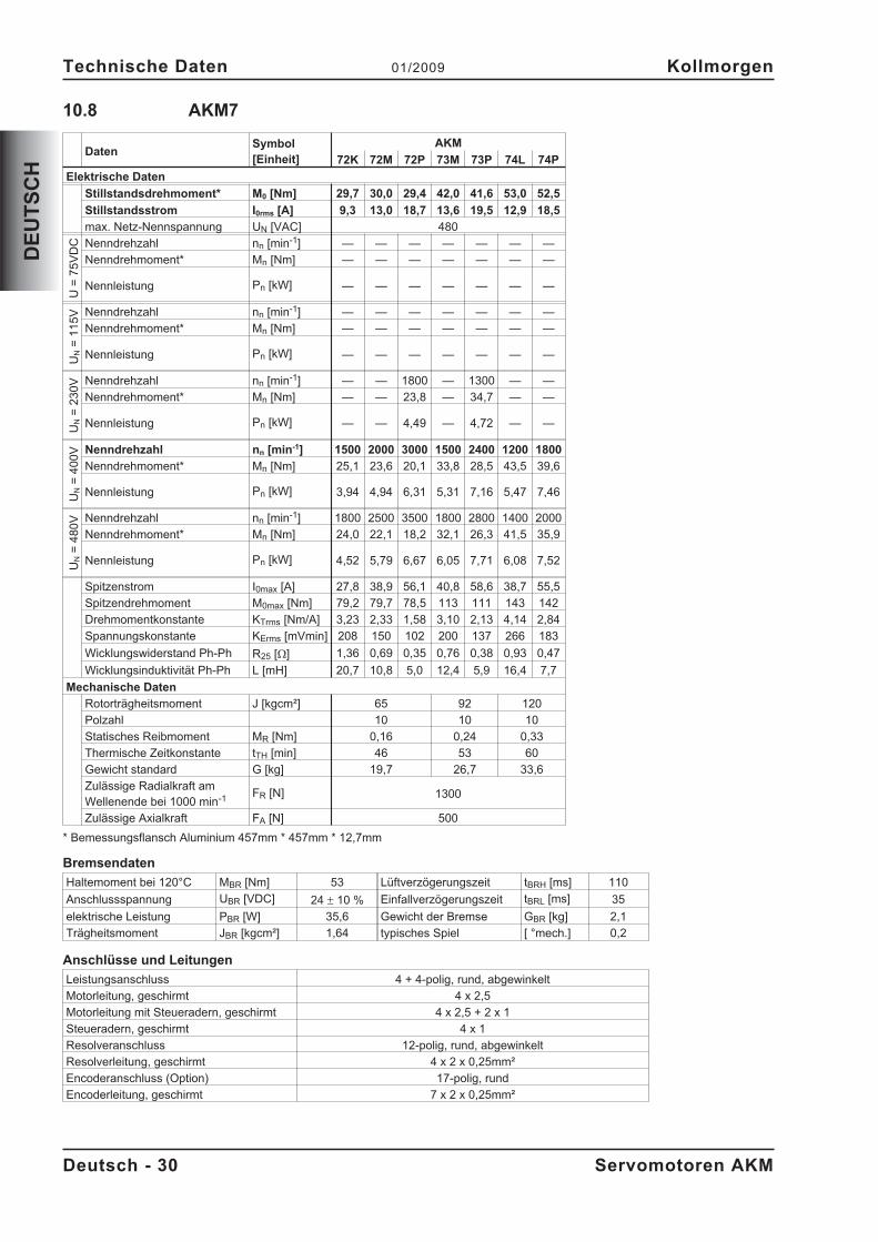
10.8 AKM7
DatenSymbol[Einheit]
AKM
72K 72M 72P 73M 73P 74L 74P
Elektrische Daten
Stillstandsdrehmoment* M0 [Nm] 29,7 30,0 29,4 42,0 41,6 53,0 52,5
Stillstandsstrom I0rms [A] 9,3 13,0 18,7 13,6 19,5 12,9 18,5
max. Netz-Nennspannung UN [VAC] 480
U=
75
VD
C Nenndrehzahl nn [min-1] — — — — — — —
Nenndrehmoment* Mn [Nm] — — — — — — —
Nennleistung Pn [kW] — — — — — — —
UN
=1
15
V Nenndrehzahl nn [min-1] — — — — — — —
Nenndrehmoment* Mn [Nm] — — — — — — —
Nennleistung Pn [kW] — — — — — — —
UN
=2
30
V Nenndrehzahl nn [min-1] — — 1800 — 1300 — —
Nenndrehmoment* Mn [Nm] — — 23,8 — 34,7 — —
Nennleistung Pn [kW] — — 4,49 — 4,72 — —
UN
=4
00
V Nenndrehzahl nn [min-1] 1500 2000 3000 1500 2400 1200 1800
Nenndrehmoment* Mn [Nm] 25,1 23,6 20,1 33,8 28,5 43,5 39,6
Nennleistung Pn [kW] 3,94 4,94 6,31 5,31 7,16 5,47 7,46
UN
=4
80
V Nenndrehzahl nn [min-1] 1800 2500 3500 1800 2800 1400 2000
Nenndrehmoment* Mn [Nm] 24,0 22,1 18,2 32,1 26,3 41,5 35,9
Nennleistung Pn [kW] 4,52 5,79 6,67 6,05 7,71 6,08 7,52
Spitzenstrom I0max [A] 27,8 38,9 56,1 40,8 58,6 38,7 55,5
Spitzendrehmoment M0max [Nm] 79,2 79,7 78,5 113 111 143 142
Drehmomentkonstante KTrms [Nm/A] 3,23 2,33 1,58 3,10 2,13 4,14 2,84
Spannungskonstante KErms [mVmin] 208 150 102 200 137 266 183
Wicklungswiderstand Ph-Ph R25 [] 1,36 0,69 0,35 0,76 0,38 0,93 0,47
Wicklungsinduktivität Ph-Ph L [mH] 20,7 10,8 5,0 12,4 5,9 16,4 7,7
Mechanische Daten
Rotorträgheitsmoment J [kgcm²] 65 92 120
Polzahl 10 10 10
Statisches Reibmoment MR [Nm] 0,16 0,24 0,33
Thermische Zeitkonstante tTH [min] 46 53 60
Gewicht standard G [kg] 19,7 26,7 33,6
Zulässige Radialkraft amWellenende bei 1000 min-1 FR [N] 1300
Zulässige Axialkraft FA [N] 500
* Bemessungsflansch Aluminium 457mm * 457mm * 12,7mm
Bremsendaten
Haltemoment bei 120°C MBR [Nm] 53 Lüftverzögerungszeit tBRH [ms] 110
Anschlussspannung UBR [VDC] 24 � 10 % Einfallverzögerungszeit tBRL [ms] 35
elektrische Leistung PBR [W] 35,6 Gewicht der Bremse GBR [kg] 2,1
Trägheitsmoment JBR [kgcm²] 1,64 typisches Spiel [ °mech.] 0,2
Anschlüsse und Leitungen
Leistungsanschluss 4 + 4-polig, rund, abgewinkelt
Motorleitung, geschirmt 4 x 2,5
Motorleitung mit Steueradern, geschirmt 4 x 2,5 + 2 x 1
Steueradern, geschirmt 4 x 1
Resolveranschluss 12-polig, rund, abgewinkelt
Resolverleitung, geschirmt 4 x 2 x 0,25mm²
Encoderanschluss (Option) 17-polig, rund
Encoderleitung, geschirmt 7 x 2 x 0,25mm²
Deutsch - 30 Servomotoren AKM
Technische Daten 01/2009 Kollmorgen
DE
UT
SC
H
11 General
11.1 About this manual
This manual describes the AKM series of synchronous servomotors (standard version). Amongother things, you find information about:
The motors are operated in drive systems together with Kollmorgen servo amplifiers. Pleaseobserve the entire system documentation, consisting of:
— Product manual for the servo amplifier— Installation and setup instructions for any expansion card which is connected— Online help of the amplifier's setup software— Accessories manual— Technical description of the AKM series of motors
11.2 Target group
This manual addresses personnel with the following qualifications:Transport : only by personnel with knowledge of handling electrostatically
sensitive components.Mech. Installation : only by mechanically qualified personnel.Electr. Installation : only by electrically qualified personnel.Setup : only by qualified personnel with extensive knowledge of electrical
engineering and drive technologyThe qualified personnel must know and observe the following standards:
IEC 60364 or IEC 60664national accident prevention regulations
The operator must ensure that the safety instructions in this manual are followed. The ope-rator must ensure that all personnel responsible for working with the motor have read andunderstood the product manual.
11.3 Symbols used
Danger to personnel from electricityand its effects
General warninggeneral instructionmechanical hazard
� see page/chapter (cross reference) � special emphasis
11.4 Abbreviations used
see chapter 20.1 "Definition of Terms".
Servomotors AKM English - 31
Kollmorgen 01/2009 General
EN
GL
ISH
12 Safety
12.1 Safety Notes
� Only properly qualified personnel are permitted to perform such tasks as transport,assembly, setup and maintenance. Properly qualified personnel are persons who arefamiliar with the transport, assembly, installation, setup and operation of motors, andwho have the appropriate qualifications for their jobs. The qualified personnel mustknow and observe the following standards and regulations:
IEC 60364 or IEC 60664national regulations for safety / accident prevention
� Read the available documentation before assembly and setup. Incorrect handling ofthe motors can result in injury and damage to persons and machinery. Keep strictlyto the technical data and the information on the connection requirements (nameplateand documentation).
� The manufacturer of the machine must generate a hazard analysis for the machine,and take appropriate measures to ensure that unforeseen movements cannot causeinjury or damage to any person or property.
� It is vital that you ensure that the motor housing is safely earthed to the PE(protectiveearth) busbar in the switch cabinet. Electrical safety is impossible without a low-re-sistance earth connection.
� Do not unplug any connectors during operation. This creates the danger of death, se-vere injury, or extensive material damage.
� Power connections may be live even when the motor is not rotating. Never discon-nect the power connections of the motor while the equipment is energised. This cancause flashovers with resulting injuries to persons and damage to the contacts.
� After disconnecting the servo amplifier from the supply voltage, wait at least five mi-nutes before touching any components which are normally live (e.g. contacts, screwconnections) or opening any connections.The capacitors in the servo amplifier can still carry a dangerous voltage up to five mi-nutes after switching off the supply voltages. To be quite safe, measure the DC-linkvoltage and wait until the voltage has fallen below 40V.
� The surfaces of the motors can be very hot in operation, according to their protectioncategory. The surface temperature can exceed 100°C. Measure the temperature, andwait until the motor has cooled down below 40°C before touching it.
� Remove any fitted key (if present) from the shaft before letting the motor run indepen-dently, to avoid the dangerous results of the key being thrown out by centrifugal for-ces.
English - 32 Servomotors AKM
Safety 01/2009 Kollmorgen
EN
GL
ISH
12.2 Use as directed
� The AKM series of synchronous servomotors is designed especially for drives for industrialrobots, machine tools, textile and packing machinery and similar with high requirements fordynamics.
� The user is only permitted to operate the motors under the ambient conditions which are de-fined in this documentation.
� The AKM series of motors is exclusively intended to be driven by servo amplifiers underspeed and / or torque control.
� The motors are installed as components in electrical apparatus or machines and can only becommissioned and put into operation as integral components of such apparatus or machi-nes.
� The thermal contact which is integrated in the motor windings must be observed and evalua-ted.
� The conformity of the servo-system to the standards mentioned in the EC Declaration ofConformity on page 34 is only guaranteed when the components (servo amplifier, motor,cables etc.) that are used have been supplied by us.
12.3 Prohibited use
� The use of the motors in the following environments is prohibited:- potentially explosive areas- environments with corrosive and/or electrically conductive acids, alkaline solutions,
oils, vapours, dusts- directly on supply networks
� Commissioning the motor is prohibited if the machine in which it was installed- does not meet the requirements of the EC Machinery Directive- does not comply with the EMC Directive- does not comply with the Low Voltage Directive
Servomotors AKM English - 33
Kollmorgen 01/2009 Safety
EN
GL
ISH
13 Standards
13.1 EC Declaration of Conformity
We, the company
Danaher Motion GmbHWacholderstrasse 40-4240489 Düsseldorf
hereby in sole responsibility declare the conformity of the product series
Motor series AKM(Types AKM1, AKM2, AKM3, AKM4, AKM5, AKM6, AKM7)
with the following standards:
- EC Directive 2004/108/ECElectromagnetic compatibilityUsed standard EN61800-3:07/2005
- EC Directive 2006/95/ECElectrical devices for use in special voltage limitsUsed standards
EN60034-1:1998+A1+A2+A3EN60034-5:2001EN60529:1991+A1EN61800-5-1:04/2008
Year of EC-Declaration 2003
Issued by: Product Manager Motors Europe
Jörg Peters
Düsseldorf, 06.01.2009
Legally valid signature
This Declaration does not contain any assurance of properties in the meaning of product liability.The notes on safety and protection in the operating instructions must always be observed.The above-mentioned company has the following technical documentation for examination:- Proper operating instructions- Diagrams (for EU authority only)- Test certificates (for EU authority only)- Other technical documentation (for EU authority only)
English - 34 Servomotors AKM
Standards 01/2009 Kollmorgen
EN
GL
ISH
14 Handling
14.1 Transport
� Transport temperature -25...+70°C, max. 20K/hr change
� Transport humidity rel. humidity 5% - 95% , no condensation
� Only by qualified personnel in the manufacturer’s original recyclable packaging
� Avoid shocks, especially to the shaft end
� If the packaging is damaged, check the motor for visible damage. Inform the carrier and, ifappropriate, the manufacturer.
14.2 Packaging
� Cardboard packing with Instapak® foam cushion.
� You can return the plastic portion to the supplier (see "Disposal").
Motor type Carton Max.stacking height Motor type Carton Max.stacking height
AKM1 X 10 AKM5 X 5
AKM2 X 10 AKM6 X 1
AKM3 X 6 AKM7 X 1
AKM4 X 6
14.3 Storage
� Storage temperature - 25...+55°C, max. variation 20K/hr.
� Humidity rel. humidity 5% - 95%, no condensation
� Store only in the manufacturer’s original recyclable packaging
� Max. stacking height see table under Packaging
� Storage time unlimited
14.4 Maintenance / Cleaning
� Maintenance and cleaning only by qualified personnel
� The ball bearings should be replaced after 20,000 hours of operation under rated conditions(by the manufacturer).
� Check the motor for bearing noise every 2500 operating hours, respectively each year. If anynoises are heard, stop the operation of the motor, the bearings must be replaced (by the ma-nufacturer).
� Opening the motor invalidates the warranty.
� If the housing is dirty, clean housing with Isopropanol or similar, do not immerse or spray
14.5 Repair
Repair of the motor must be done by the manufacturer. Opening the motor invalidates the warranty.Send the motor to:
Danaher Motion GmbHWacholderstr. 40-42D-40489 Düsseldorf
14.6 Disposal
In accordance to the WEEE-2002/96/EG-Guidelines we take old devices and accessories back forprofessional disposal, if the transport costs are taken over by the sender. Send the devices to:
Danaher Motion GmbHWacholderstr. 40-42D-40489 Düsseldorf
Servomotors AKM English - 35
Kollmorgen 01/2009 Handling
EN
GL
ISH
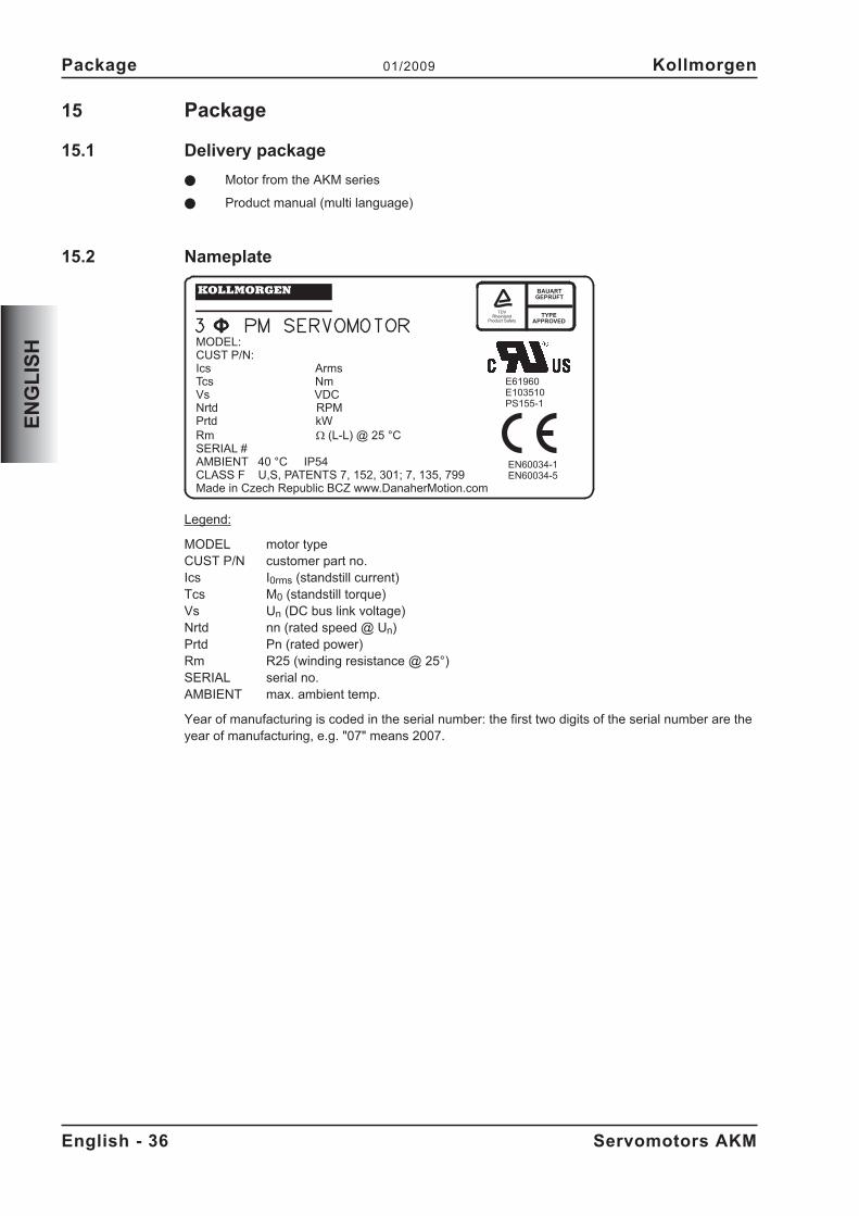
15 Package
15.1 Delivery package
� Motor from the AKM series
� Product manual (multi language)
15.2 Nameplate
Legend:
MODEL motor typeCUST P/N customer part no.Ics I0rms (standstill current)Tcs M0 (standstill torque)Vs Un (DC bus link voltage)Nrtd nn (rated speed @ Un)Prtd Pn (rated power)Rm R25 (winding resistance @ 25°)SERIAL serial no.AMBIENT max. ambient temp.
Year of manufacturing is coded in the serial number: the first two digits of the serial number are theyear of manufacturing, e.g. "07" means 2007.
English - 36 Servomotors AKM
Package 01/2009 Kollmorgen
EN
GL
ISH
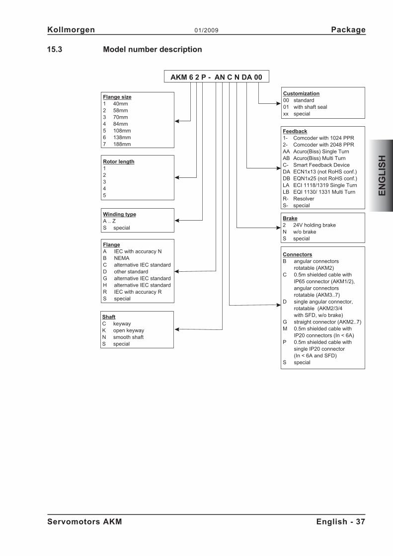
15.3 Model number description
Servomotors AKM English - 37
Kollmorgen 01/2009 Package
EN
GL
ISH
Flange size1 40mm2 58mm3 70mm4 84mm5 108mm6 138mm7 188mm
FlangeA IEC with accuracy NB NEMAC alternative IEC standardD other standardG alternative IEC standardH alternative IEC standardR IEC with accuracy RS special
Rotor length12345
Winding typeA .. ZS special
ConnectorsB angular connectors
rotatable (AKM2)C 0.5m shielded cable with
IP65 connector (AKM1/2),angular connectorsrotatable (AKM3..7)
D single angular connector,rotatable (AKM2/3/4with SFD, w/o brake)
G straight connector (AKM2..7)M 0.5m shielded cable with
IP20 connectors (In < 6A)P 0.5m shielded cable with
single IP20 connector(In < 6A and SFD)
S special
Brake2 24V holding brakeN w/o brakeS special
Feedback1- Comcoder with 1024 PPR2- Comcoder with 2048 PPRAA Acuro(Biss) Single TurnAB Acuro(Biss) Multi TurnC- Smart Feedback DeviceDA ECN1x13 (not RoHS conf.)DB EQN1x25 (not RoHS conf.)LA ECI 1118/1319 Single TurnLB EQI 1130/ 1331 Multi TurnR- ResolverS- special
Customization00 standard01 with shaft sealxx special
ShaftC keywayK open keywayN smooth shaftS special
AKM 6 2 P - AN C N DA 00
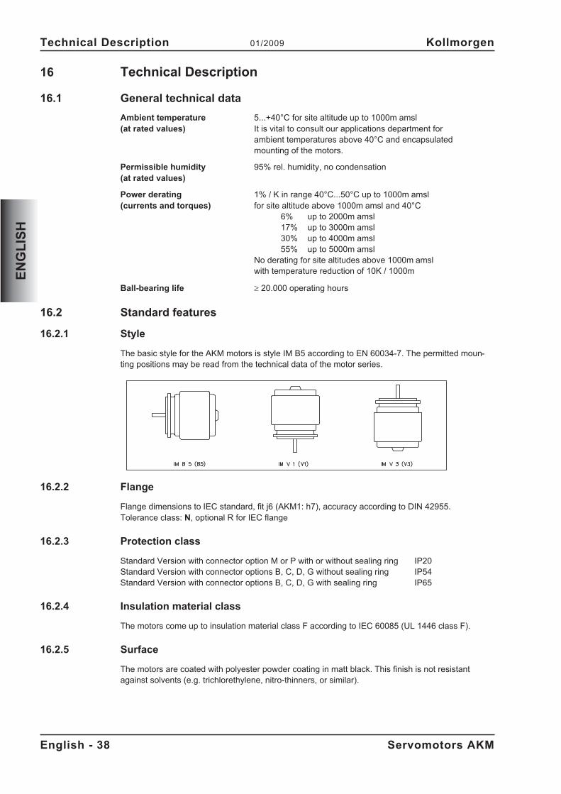
16 Technical Description
16.1 General technical data
Ambient temperature 5...+40°C for site altitude up to 1000m amsl(at rated values) It is vital to consult our applications department for
ambient temperatures above 40°C and encapsulatedmounting of the motors.
Permissible humidity 95% rel. humidity, no condensation(at rated values)
Power derating 1% / K in range 40°C...50°C up to 1000m amsl(currents and torques) for site altitude above 1000m amsl and 40°C
6% up to 2000m amsl17% up to 3000m amsl30% up to 4000m amsl55% up to 5000m amsl
No derating for site altitudes above 1000m amslwith temperature reduction of 10K / 1000m
Ball-bearing life � 20.000 operating hours
16.2 Standard features
16.2.1 Style
The basic style for the AKM motors is style IM B5 according to EN 60034-7. The permitted moun-ting positions may be read from the technical data of the motor series.
16.2.2 Flange
Flange dimensions to IEC standard, fit j6 (AKM1: h7), accuracy according to DIN 42955.Tolerance class: N, optional R for IEC flange
16.2.3 Protection class
Standard Version with connector option M or P with or without sealing ring IP20Standard Version with connector options B, C, D, G without sealing ring IP54Standard Version with connector options B, C, D, G with sealing ring IP65
16.2.4 Insulation material class
The motors come up to insulation material class F according to IEC 60085 (UL 1446 class F).
16.2.5 Surface
The motors are coated with polyester powder coating in matt black. This finish is not resistantagainst solvents (e.g. trichlorethylene, nitro-thinners, or similar).
English - 38 Servomotors AKM
Technical Description 01/2009 Kollmorgen
EN
GL
ISH
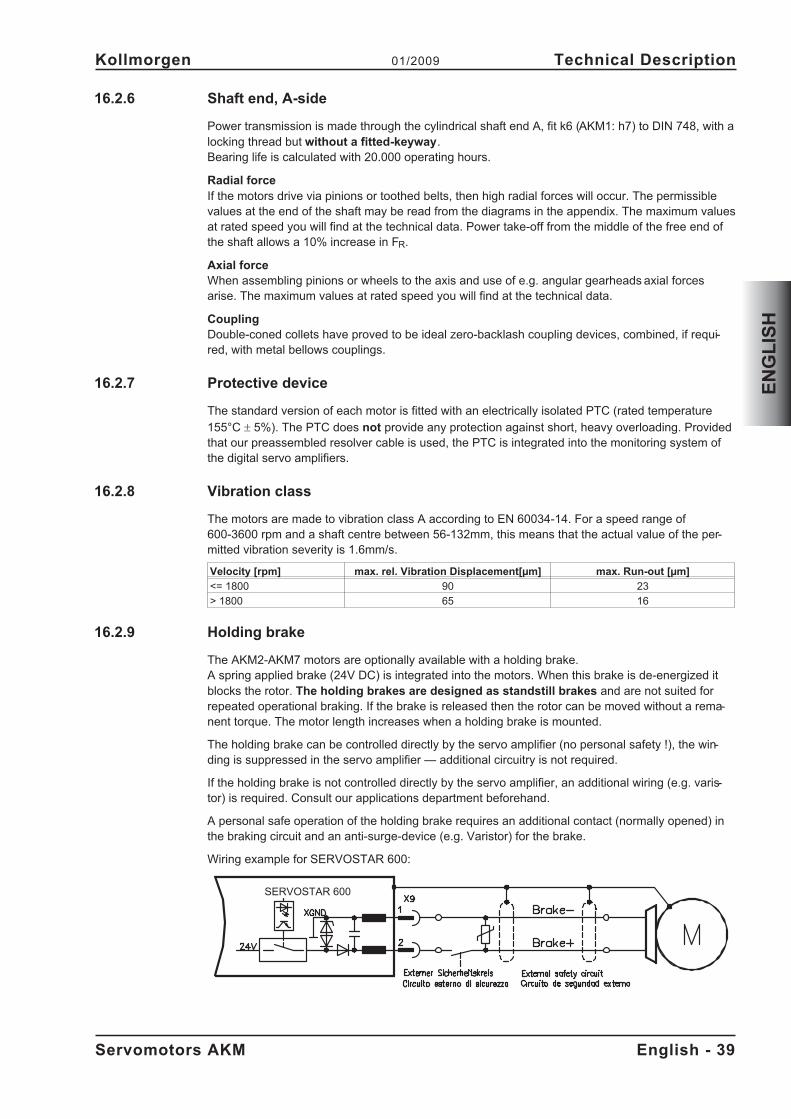
16.2.6 Shaft end, A-side
Power transmission is made through the cylindrical shaft end A, fit k6 (AKM1: h7) to DIN 748, with alocking thread but without a fitted-keyway.Bearing life is calculated with 20.000 operating hours.
Radial forceIf the motors drive via pinions or toothed belts, then high radial forces will occur. The permissiblevalues at the end of the shaft may be read from the diagrams in the appendix. The maximum valuesat rated speed you will find at the technical data. Power take-off from the middle of the free end ofthe shaft allows a 10% increase in FR.
Axial forceWhen assembling pinions or wheels to the axis and use of e.g. angular gearheads axial forcesarise. The maximum values at rated speed you will find at the technical data.
CouplingDouble-coned collets have proved to be ideal zero-backlash coupling devices, combined, if requi-red, with metal bellows couplings.
16.2.7 Protective device
The standard version of each motor is fitted with an electrically isolated PTC (rated temperature
155°C � 5%). The PTC does not provide any protection against short, heavy overloading. Providedthat our preassembled resolver cable is used, the PTC is integrated into the monitoring system ofthe digital servo amplifiers.
16.2.8 Vibration class
The motors are made to vibration class A according to EN 60034-14. For a speed range of600-3600 rpm and a shaft centre between 56-132mm, this means that the actual value of the per-mitted vibration severity is 1.6mm/s.
Velocity [rpm] max. rel. Vibration Displacement[µm] max. Run-out [µm]
<= 1800 90 23
> 1800 65 16
16.2.9 Holding brake
The AKM2-AKM7 motors are optionally available with a holding brake.A spring applied brake (24V DC) is integrated into the motors. When this brake is de-energized itblocks the rotor. The holding brakes are designed as standstill brakes and are not suited forrepeated operational braking. If the brake is released then the rotor can be moved without a rema-nent torque. The motor length increases when a holding brake is mounted.
The holding brake can be controlled directly by the servo amplifier (no personal safety !), the win-ding is suppressed in the servo amplifier — additional circuitry is not required.
If the holding brake is not controlled directly by the servo amplifier, an additional wiring (e.g. varis-tor) is required. Consult our applications department beforehand.
A personal safe operation of the holding brake requires an additional contact (normally opened) inthe braking circuit and an anti-surge-device (e.g. Varistor) for the brake.
Wiring example for SERVOSTAR 600:
Servomotors AKM English - 39
Kollmorgen 01/2009 Technical Description
EN
GL
ISH
SERVOSTAR 600
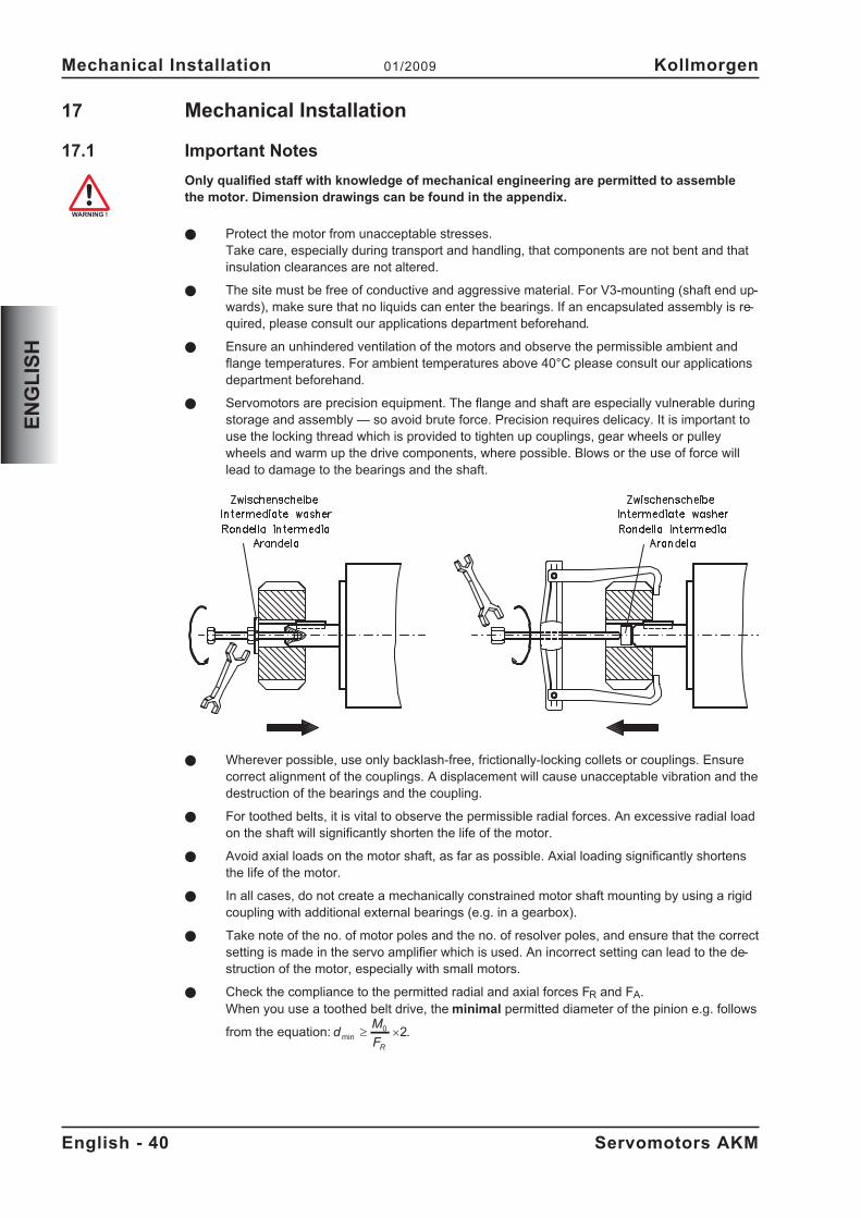
17 Mechanical Installation
17.1 Important Notes
Only qualified staff with knowledge of mechanical engineering are permitted to assemblethe motor. Dimension drawings can be found in the appendix.
� Protect the motor from unacceptable stresses.Take care, especially during transport and handling, that components are not bent and thatinsulation clearances are not altered.
� The site must be free of conductive and aggressive material. For V3-mounting (shaft end up-wards), make sure that no liquids can enter the bearings. If an encapsulated assembly is re-quired, please consult our applications department beforehand.
� Ensure an unhindered ventilation of the motors and observe the permissible ambient andflange temperatures. For ambient temperatures above 40°C please consult our applicationsdepartment beforehand.
� Servomotors are precision equipment. The flange and shaft are especially vulnerable duringstorage and assembly — so avoid brute force. Precision requires delicacy. It is important touse the locking thread which is provided to tighten up couplings, gear wheels or pulleywheels and warm up the drive components, where possible. Blows or the use of force willlead to damage to the bearings and the shaft.
� Wherever possible, use only backlash-free, frictionally-locking collets or couplings. Ensurecorrect alignment of the couplings. A displacement will cause unacceptable vibration and thedestruction of the bearings and the coupling.
� For toothed belts, it is vital to observe the permissible radial forces. An excessive radial loadon the shaft will significantly shorten the life of the motor.
� Avoid axial loads on the motor shaft, as far as possible. Axial loading significantly shortensthe life of the motor.
� In all cases, do not create a mechanically constrained motor shaft mounting by using a rigidcoupling with additional external bearings (e.g. in a gearbox).
� Take note of the no. of motor poles and the no. of resolver poles, and ensure that the correctsetting is made in the servo amplifier which is used. An incorrect setting can lead to the de-struction of the motor, especially with small motors.
� Check the compliance to the permitted radial and axial forces FR and FA.When you use a toothed belt drive, the minimal permitted diameter of the pinion e.g. follows
from the equation: dM
FR
min � �0 2.
English - 40 Servomotors AKM
Mechanical Installation 01/2009 Kollmorgen
EN
GL
ISH
18 Electrical Installation
18.1 Safety notes
Only staff qualified and trained in electrical engineering are allowed to wire up the motor.Wiring diagrams can be found in the appendix.
Always make sure that the motors are de-energized during assembly and wiring, i.e. No vol-tage may be switched on for any piece of equipment which is to be connected. Ensure thatthe switch cabinet remains turned off (barrier, warning signs etc.). The individual voltageswill only be turned on again during setup.
Never undo the electrical connections to the motor while it is energised. A dangerous volta-ge, resulting from residual charge, can be still present on the capacitors up to 5 minutes af-ter switch-off of the mains supply. Measure the DC-link voltage and wait until it has fallenbelow 40V. Even when the motor is not rotating, control and power leads may be live.
The ground symbol�, which you will find in the wiring diagrams, indicates that youmust provide an electrical connection, with as large a surface area as possible, between theunit indicated and the mounting plate in the switch cabinet. This connection is to suppressHF interference and must not be confused with the PE (protective earth) symbol (protectivemeasure to EN 60204).To wire up the motor, use the wiring diagrams in the Installation and Setup Instructions ofthe servo amplifier which is used.
18.2 Guide for electrical installation
� Check that the servo amplifier and motor match each other. Compare the rated voltage andrated current of the unit. Carry out the wiring according to the wiring diagram in the productmanual of the servo amplifier. The connections to the motor are shown in the appendix.
� Ensure that there is proper earthing of the servo amplifier and the motor. Use correct eart-hing and EMC-shielding according to the product manual of the servo amplifier which isused. Earth the mounting plate and motor casing.
� Route the power and control cables as separately as possible from one another (separation> 20 cm). This will improve the immunity of the system to electromagnetic interference.If a motor power cable is used which includes integral brake control leads, then these brakecontrol leads must be shielded. The shielding must be connected at both ends (see productmanual of the servo amplifier).
� Cabling:— Route power cables as separately as possible from control cables— Connect up the resolver or encoder.— Connect the motor cables, install motor chokes close to the servo amplifier— Connect shields to shielding terminals or EMC connectors at both ends— Connect the holding brake, if used— Connect shielding at both ends.
� Install all cables carrying a heavy current with an adequate cross-section, as per EN 60204.The recommended cross-section can be found in the Technical data.
In case of long motor cables (>25m) and dependent on the type of the used servo am-plifier a motor choke (3YL) must be switched into the motor cable (see product manu-al of the servo amplifier and accessory manual).
� Connect up all shielding via a wide surface-area contact (low impedance) and metallizedconnector housings or EMC-cable glands.
Servomotors AKM English - 41
Kollmorgen 01/2009 Electrical Installation
EN
GL
ISH
18.3 Connection of the motors with preassembled cables
� Carry out the wiring in accordance with the valid standards and regulations. Wiringdiagrams can be found in the appendix.
� Only use our preassembled shielded cables for the resolver and power connections.
� Connect up the shielding according to the wiring diagrams in the product manual forthe servo amplifier.
� Incorrectly installed shielding inevitably cables to EMC interference.
� The maximum cable length is defined in the product manual of the used servo ampli-fier.
Requirements to cable material:
CapacityMotor cable less than 150 pF/mResolver cable less than 120 pF/m
For a detailed description of preassembled cables, please refer to the accessories manual.
English - 42 Servomotors AKM
Electrical Installation 01/2009 Kollmorgen
EN
GL
ISH
19 Setup
19.1 Important notes
Only specialist personnel with extensive knowledge in the areas of electrical engineering /drive technology are allowed to commission the drive unit of servo amplifier and motor.
Check that all live connection points (terminal boxes) are safe against accidental contact.Deadly voltages can occur, up to 900V.
Never undo the electrical connections to the motor when it is live. The residual charge in thecapacitors of the servo amplifier can produce dangerous voltages up to 5 minutes after themains supply has been switched off.
The surface temperature of the motor can exceed 100°C in operation. Check (measure) thetemperature of the motor. Wait until the motor has cooled down below 40°C before touchingit.
Make sure that, even if the drive starts to move unintentionally, no danger can result for per-sonnel or machinery.
19.2 Guide for setup
The procedure for setup is described as an example. A different method may be appropriate ornecessary, depending on the application of the equipment.
� Check the assembly and orientation of the motor.
� Check the drive components (clutch, gear unit, belt pulley) for the correct seating and setting(observe the permissible radial and axial forces).
� Check the wiring and connections to the motor and the servo amplifier. Check that the eart-hing is correct.
� Test the function of the holding brake, if used. (apply 24V, the brake must be released).
� Check whether the rotor of the motor revolves freely (release the brake, if necessary). Listenout for grinding noises.
� Check that all the required measures against accidental contact with live and moving partshave been carried out.
� Carry out any further tests which are specifically required for your system.
� Now commission the drive according to the setup instructions for the servo amplifier.
� In multi-axis systems, individually commission each drive unit (servo amplifier and motor).
Servomotors AKM English - 43
Kollmorgen 01/2009 Setup
EN
GL
ISH
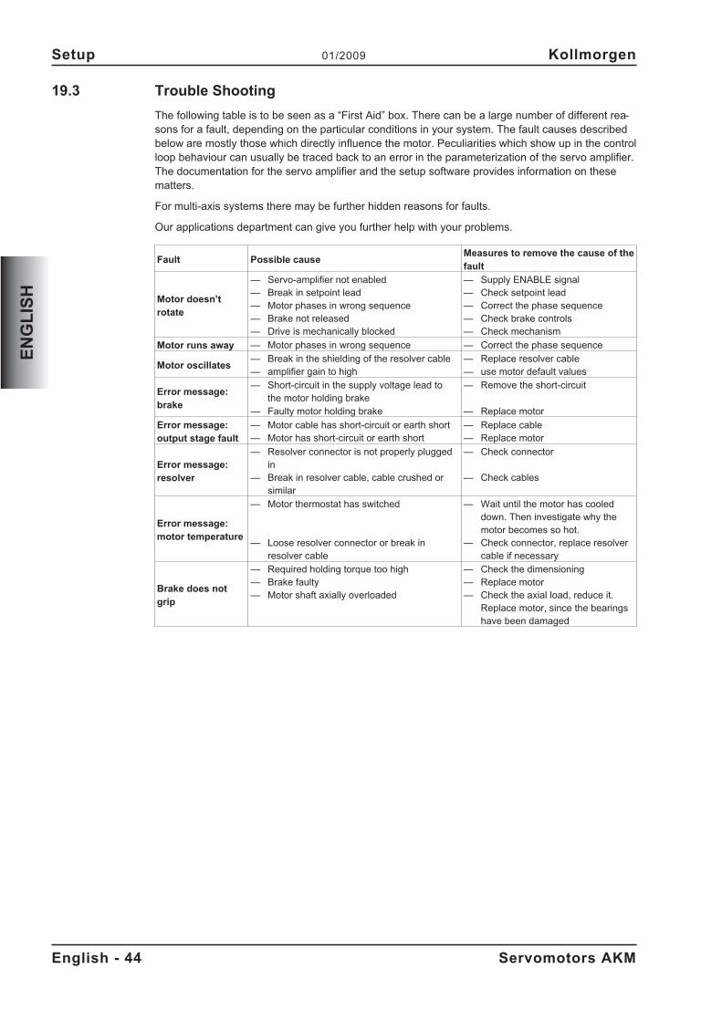
19.3 Trouble Shooting
The following table is to be seen as a “First Aid” box. There can be a large number of different rea-sons for a fault, depending on the particular conditions in your system. The fault causes describedbelow are mostly those which directly influence the motor. Peculiarities which show up in the controlloop behaviour can usually be traced back to an error in the parameterization of the servo amplifier.The documentation for the servo amplifier and the setup software provides information on thesematters.
For multi-axis systems there may be further hidden reasons for faults.
Our applications department can give you further help with your problems.
Fault Possible causeMeasures to remove the cause of thefault
Motor doesn’trotate
— Servo-amplifier not enabled— Break in setpoint lead— Motor phases in wrong sequence— Brake not released— Drive is mechanically blocked
— Supply ENABLE signal— Check setpoint lead— Correct the phase sequence— Check brake controls— Check mechanism
Motor runs away — Motor phases in wrong sequence — Correct the phase sequence
Motor oscillates— Break in the shielding of the resolver cable— amplifier gain to high
— Replace resolver cable— use motor default values
Error message:brake
— Short-circuit in the supply voltage lead tothe motor holding brake
— Faulty motor holding brake
— Remove the short-circuit
— Replace motor
Error message:output stage fault
— Motor cable has short-circuit or earth short— Motor has short-circuit or earth short
— Replace cable— Replace motor
Error message:resolver
— Resolver connector is not properly pluggedin
— Break in resolver cable, cable crushed orsimilar
— Check connector
— Check cables
Error message:motor temperature
— Motor thermostat has switched
— Loose resolver connector or break inresolver cable
— Wait until the motor has cooleddown. Then investigate why themotor becomes so hot.
— Check connector, replace resolvercable if necessary
Brake does notgrip
— Required holding torque too high— Brake faulty— Motor shaft axially overloaded
— Check the dimensioning— Replace motor— Check the axial load, reduce it.
Replace motor, since the bearingshave been damaged
English - 44 Servomotors AKM
Setup 01/2009 Kollmorgen
EN
GL
ISH
20 Technical Data
All data valid for 40°C environmental temperature and 100K overtemperature of the winding. Thedata can have a tolerance of +/- 10%.
20.1 Definition of Terms
Standstill torque M0 [Nm]The standstill torque can be maintained indefinitely at a speed 0<n<100 rpm and rated ambient con-ditions.
Rated torque Mn [Nm]The rated torque is produced when the motor is drawing the rated current at the rated speed. Therated torque can be produced indefinitely at the rated speed in continuous operation (S1).
Standstill current I0rms [A]The standstill current is the effective sinusoidal current which the motor draws at 0<n<100 rpm toproduce the standstill torque.
Peak current (pulse current) I0max [A]The peak current (effective sinusoidal value) is approximately equivalent to 4-times the rated cur-rent. The actual value is determined by the peak current of the servo amplifier which is used.
Torque constant KTrms [Nm/A]The torque constant defines how much torque in Nm is produced by the motor with 1A r.m.s. cur-rent. The relationship is M=I x KT (up to I = 2 x I0)
Voltage constant KErms [mV/min-1]The voltage constant defines the induced motor EMF, as an effective sinusoidal value between twoterminals, per 1000 rpm
Rotor moment of inertia J [kgcm²]The constant J is a measure of the acceleration capability of the motor. For instance, at I0 the acce-leration time tb from 0 to 3000 rpm is given as:
t sM s
m
cmJ
b[ ] �
�
��
��
3000 2
60 100
2
4 2
�with M0 in Nm and J in kgcm²
Thermal time constant tth [min]The constant tth defines the time for the cold motor, under a load of I0, to heat up to an overtempe-rature of 0.63 x 10⁵ Kelvin. This temperature rise happens in a much shorter time when the motor isloaded with the rated current.
Release delay time tBRH [ms] / Application delay time tBRL [ms] of the brakeThese constants define the response times of the holding brake when operated with the rated vol-tage from the servo amplifier.
UN
Rated mains voltage
Un
DC-Bus link voltage. U Un N
� �2
Servomotors AKM English - 45
Kollmorgen 01/2009 Technical Data
EN
GL
ISH
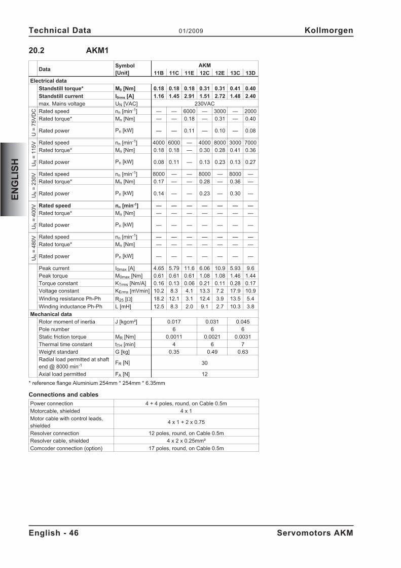
20.2 AKM1
DataSymbol[Unit]
AKM
11B 11C 11E 12C 12E 13C 13D
Electrical data
Standstill torque* M0 [Nm] 0.18 0.18 0.18 0.31 0.31 0.41 0.40
Standstill current I0rms [A] 1.16 1.45 2.91 1.51 2.72 1.48 2.40
max. Mains voltage UN [VAC] 230VAC
U=
75
VD
C Rated speed nn [min-1] — — 6000 — 3000 — 2000
Rated torque* Mn [Nm] — — 0.18 — 0.31 — 0.40
Rated power Pn [kW] — — 0.11 — 0.10 — 0.08
UN
=1
15
V Rated speed nn [min-1] 4000 6000 — 4000 8000 3000 7000
Rated torque* Mn [Nm] 0.18 0.18 — 0.30 0.28 0.41 0.36
Rated power Pn [kW] 0.08 0.11 — 0.13 0.23 0.13 0.27
UN
=2
30
V Rated speed nn [min-1] 8000 — — 8000 — 8000 —
Rated torque* Mn [Nm] 0.17 — — 0.28 — 0.36 —
Rated power Pn [kW] 0.14 — — 0.23 — 0.30 —
UN
=4
00
V Rated speed nn [min-1] — — — — — — —
Rated torque* Mn [Nm] — — — — — — —
Rated power Pn [kW] — — — — — — —
UN
=4
80
V Rated speed nn [min-1] — — — — — — —
Rated torque* Mn [Nm] — — — — — — —
Rated power Pn [kW] — — — — — — —
Peak current I0max [A] 4.65 5.79 11.6 6.06 10.9 5.93 9.6
Peak torque M0max [Nm] 0.61 0.61 0.61 1.08 1.08 1.46 1.44
Torque constant KTrms [Nm/A] 0.16 0.13 0.06 0.21 0.11 0.28 0.17
Voltage constant KErms [mVmin] 10.2 8.3 4.1 13.3 7.2 17.9 10.9
Winding resistance Ph-Ph R25 [] 18.2 12.1 3.1 12.4 3.9 13.5 5.4
Winding inductance Ph-Ph L [mH] 12.5 8.3 2.0 9.1 2.7 10.3 3.8
Mechanical data
Rotor moment of inertia J [kgcm²] 0.017 0.031 0.045
Pole number 6 6 6
Static friction torque MR [Nm] 0.0011 0.0021 0.0031
Thermal time constant tTH [min] 4 6 7
Weight standard G [kg] 0.35 0.49 0.63
Radial load permitted at shaftend @ 8000 min-1 FR [N] 30
Axial load permitted FA [N] 12
* reference flange Aluminium 254mm * 254mm * 6.35mm
Connections and cables
Power connection 4 + 4 poles, round, on Cable 0.5m
Motorcable, shielded 4 x 1
Motor cable with control leads,shielded
4 x 1 + 2 x 0.75
Resolver connection 12 poles, round, on Cable 0.5m
Resolver cable, shielded 4 x 2 x 0.25mm²
Comcoder connection (option) 17 poles, round, on Cable 0.5m
English - 46 Servomotors AKM
Technical Data 01/2009 Kollmorgen
EN
GL
ISH
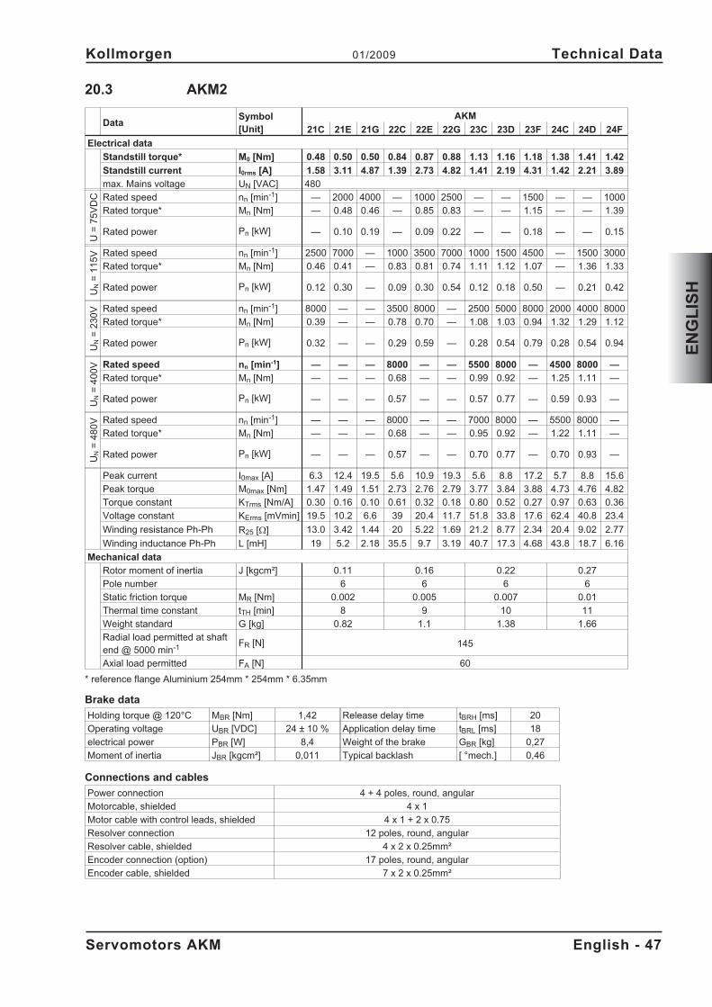
20.3 AKM2
DataSymbol[Unit]
AKM
21C 21E 21G 22C 22E 22G 23C 23D 23F 24C 24D 24F
Electrical data
Standstill torque* M0 [Nm] 0.48 0.50 0.50 0.84 0.87 0.88 1.13 1.16 1.18 1.38 1.41 1.42
Standstill current I0rms [A] 1.58 3.11 4.87 1.39 2.73 4.82 1.41 2.19 4.31 1.42 2.21 3.89
max. Mains voltage UN [VAC] 480
U=
75
VD
C Rated speed nn [min-1] — 2000 4000 — 1000 2500 — — 1500 — — 1000
Rated torque* Mn [Nm] — 0.48 0.46 — 0.85 0.83 — — 1.15 — — 1.39
Rated power Pn [kW] — 0.10 0.19 — 0.09 0.22 — — 0.18 — — 0.15
UN
=1
15
V Rated speed nn [min-1] 2500 7000 — 1000 3500 7000 1000 1500 4500 — 1500 3000
Rated torque* Mn [Nm] 0.46 0.41 — 0.83 0.81 0.74 1.11 1.12 1.07 — 1.36 1.33
Rated power Pn [kW] 0.12 0.30 — 0.09 0.30 0.54 0.12 0.18 0.50 — 0.21 0.42
UN
=2
30
V Rated speed nn [min-1] 8000 — — 3500 8000 — 2500 5000 8000 2000 4000 8000
Rated torque* Mn [Nm] 0.39 — — 0.78 0.70 — 1.08 1.03 0.94 1.32 1.29 1.12
Rated power Pn [kW] 0.32 — — 0.29 0.59 — 0.28 0.54 0.79 0.28 0.54 0.94
UN
=4
00
V Rated speed nn [min-1] — — — 8000 — — 5500 8000 — 4500 8000 —
Rated torque* Mn [Nm] — — — 0.68 — — 0.99 0.92 — 1.25 1.11 —
Rated power Pn [kW] — — — 0.57 — — 0.57 0.77 — 0.59 0.93 —
UN
=4
80
V Rated speed nn [min-1] — — — 8000 — — 7000 8000 — 5500 8000 —
Rated torque* Mn [Nm] — — — 0.68 — — 0.95 0.92 — 1.22 1.11 —
Rated power Pn [kW] — — — 0.57 — — 0.70 0.77 — 0.70 0.93 —
Peak current I0max [A] 6.3 12.4 19.5 5.6 10.9 19.3 5.6 8.8 17.2 5.7 8.8 15.6
Peak torque M0max [Nm] 1.47 1.49 1.51 2.73 2.76 2.79 3.77 3.84 3.88 4.73 4.76 4.82
Torque constant KTrms [Nm/A] 0.30 0.16 0.10 0.61 0.32 0.18 0.80 0.52 0.27 0.97 0.63 0.36
Voltage constant KErms [mVmin] 19.5 10.2 6.6 39 20.4 11.7 51.8 33.8 17.6 62.4 40.8 23.4
Winding resistance Ph-Ph R25 [] 13.0 3.42 1.44 20 5.22 1.69 21.2 8.77 2.34 20.4 9.02 2.77
Winding inductance Ph-Ph L [mH] 19 5.2 2.18 35.5 9.7 3.19 40.7 17.3 4.68 43.8 18.7 6.16
Mechanical data
Rotor moment of inertia J [kgcm²] 0.11 0.16 0.22 0.27
Pole number 6 6 6 6
Static friction torque MR [Nm] 0.002 0.005 0.007 0.01
Thermal time constant tTH [min] 8 9 10 11
Weight standard G [kg] 0.82 1.1 1.38 1.66
Radial load permitted at shaftend @ 5000 min-1 FR [N] 145
Axial load permitted FA [N] 60
* reference flange Aluminium 254mm * 254mm * 6.35mm
Brake data
Holding torque @ 120°C MBR [Nm] 1,42 Release delay time tBRH [ms] 20
Operating voltage UBR [VDC] 24 ± 10 % Application delay time tBRL [ms] 18
electrical power PBR [W] 8,4 Weight of the brake GBR [kg] 0,27
Moment of inertia JBR [kgcm²] 0,011 Typical backlash [ °mech.] 0,46
Connections and cables
Power connection 4 + 4 poles, round, angular
Motorcable, shielded 4 x 1
Motor cable with control leads, shielded 4 x 1 + 2 x 0.75
Resolver connection 12 poles, round, angular
Resolver cable, shielded 4 x 2 x 0.25mm²
Encoder connection (option) 17 poles, round, angular
Encoder cable, shielded 7 x 2 x 0.25mm²
Servomotors AKM English - 47
Kollmorgen 01/2009 Technical Data
EN
GL
ISH
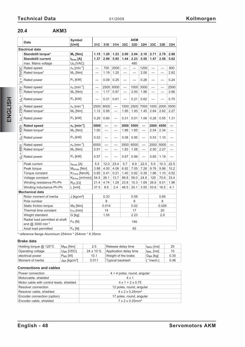
20.4 AKM3
DataSymbol[Unit]
AKM
31C 31E 31H 32C 32D 32H 33C 33E 33H
Electrical data
Standstill torque* M0 [Nm] 1.15 1.20 1.23 2.00 2.04 2.10 2.71 2.79 2.88
Standstill current I0rms [A] 1.37 2.99 5.85 1.44 2.23 5.50 1.47 2.58 5.62
max. Mains voltage UN [VAC] 480
U=
75
VD
C Rated speed nn [min-1] — 750 2000 — — 1200 — — 800
Rated torque* Mn [Nm] — 1.19 1.20 — — 2.06 — — 2.82
Rated power Pn [kW] — 0.09 0.25 — — 0.26 — — 0.24
UN
=1
15
V Rated speed nn [min-1] — 2500 6000 — 1000 3000 — — 2500
Rated torque* Mn [Nm] — 1.17 0.97 — 2.00 1.96 — — 2.66
Rated power Pn [kW] — 0.31 0.61 — 0.21 0.62 — — 0.70
UN
=2
30
V Rated speed nn [min-1] 2500 6000 — 1500 2500 7000 1000 2000 5500
Rated torque* Mn [Nm] 1.12 0.95 — 1.95 1.93 1.45 2.64 2.62 2.27
Rated power Pn [kW] 0.29 0.60 — 0.31 0.51 1.06 0.28 0.55 1.31
UN
=4
00
V Rated speed nn [min-1] 5000 — — 3000 5500 — 2000 4500 —
Rated torque* Mn [Nm] 1.00 — — 1.86 1.65 — 2.54 2.34 —
Rated power Pn [kW] 0.52 — — 0.58 0.95 — 0.53 1.10 —
UN
=4
80
V Rated speed nn [min-1] 6000 — — 3500 6000 — 2500 5000 —
Rated torque* Mn [Nm] 0.91 — — 1.83 1.58 — 2.50 2.27 —
Rated power Pn [kW] 0.57 — — 0.67 0.99 — 0.65 1.19 —
Peak current I0max [A] 5.5 12.0 23.4 5.7 8.9 22.0 5.9 10.3 22.5
Peak torque M0max [Nm] 3.88 4.00 4.06 6.92 7.05 7.26 9.76 9.96 10.2
Torque constant KTrms [Nm/A] 0.85 0.41 0.21 1.40 0.92 0.39 1.86 1.10 0.52
Voltage constant KErms [mVmin] 54.5 26.1 13.7 89.8 59.0 24.8 120 70.6 33.4
Winding resistance Ph-Ph R25 [] 21.4 4.74 1.29 23.8 10.3 1.69 26.6 9.01 1.96
Winding inductance Ph-Ph L [mH] 37.5 8.6 2.4 46.5 20.1 3.55 53.6 18.5 4.1
Mechanical data
Rotor moment of inertia J [kgcm²] 0.33 0.59 0.85
Pole number 8 8 8
Static friction torque MR [Nm] 0.014 0.02 0.026
Thermal time constant tTH [min] 14 17 20
Weight standard G [kg] 1.55 2.23 2.9
Radial load permitted at shaftend @ 3000 min-1 FR [N] 195
Axial load permitted FA [N] 65
* reference flange Aluminium 254mm * 254mm * 6.35mm
Brake data
Holding torque @ 120°C MBR [Nm] 2.5 Release delay time tBRH [ms] 25
Operating voltage UBR [VDC] 24 ± 10 % Application delay time tBRL [ms] 10
electrical power PBR [W] 10.1 Weight of the brake GBR [kg] 0.35
Moment of inertia JBR [kgcm²] 0.011 Typical backlash [ °mech.] 0.46
Connections and cables
Power connection 4 + 4 poles, round, angular
Motorcable, shielded 4 x 1
Motor cable with control leads, shielded 4 x 1 + 2 x 0.75
Resolver connection 12 poles, round, angular
Resolver cable, shielded 4 x 2 x 0.25mm²
Encoder connection (option) 17 poles, round, angular
Encoder cable, shielded 7 x 2 x 0.25mm²
English - 48 Servomotors AKM
Technical Data 01/2009 Kollmorgen
EN
GL
ISH
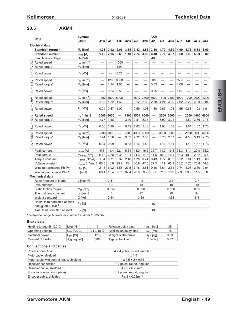
20.5 AKM4
DataSymbol[Unit]
AKM
41C 41E 41H 42C 42E 42G 42J 43E 43G 43K 44E 44G 44J
Electrical data
Standstill torque* M0 [Nm] 1.95 2.02 2.06 3.35 3.42 3.53 3.56 4.70 4.80 4.90 5.76 5.88 6.00
Standstill current I0rms [A] 1.46 2.85 5.60 1.40 2.74 4.80 8.40 2.76 4.87 9.60 2.90 5.00 8.80
max. Mains voltage UN [VAC] 480
U=
75
VD
C Rated speed nn [min-1] — — 1000 — — — — — — — — — —
Rated torque* Mn [Nm] — — 1.99 — — — — — — — — — —
Rated power Pn [kW] — — 0.21 — — — — — — — — — —
UN
=1
15
V Rated speed nn [min-1] — 1200 3000 — — — 3000 — — 2500 — — —
Rated torque* Mn [Nm] — 1.94 1.86 — — — 3.03 — — 4.08 — — —
Rated power Pn [kW] — 0.24 0.58 — — — 0.95 — — 1.07 — — —
UN
=2
30
V Rated speed nn [min-1] 1200 3000 6000 — 1800 3500 6000 1500 2500 6000 1200 2000 4000
Rated torque* Mn [Nm] 1.88 1.82 1.62 — 3.12 2.90 2.38 4.24 4.00 2.62 5.22 4.90 3.84
Rated power Pn [kW] 0.24 0.57 1.02 — 0.59 1.06 1.50 0.67 1.05 1.65 0.66 1.03 1.61
UN
=4
00
V Rated speed nn [min-1] 3000 6000 — 1500 3500 6000 — 2500 5000 — 2000 4000 6000
Rated torque* Mn [Nm] 1.77 1.58 — 3.10 2.81 2.35 — 3.92 3.01 — 4.80 3.76 2.75
Rated power Pn [kW] 0.56 0.99 — 0.49 1.03 1.48 — 1.03 1.58 — 1.01 1.57 1.73
UN
=4
80
V Rated speed nn [min-1] 3500 6000 — 2000 4000 6000 — 3000 6000 — 2500 5000 6000
Rated torque* Mn [Nm] 1.74 1.58 — 3.02 2.72 2.35 — 3.76 2.57 — 4.56 3.19 2.75
Rated power Pn [kW] 0.64 0.99 — 0.63 1.14 1.48 — 1.18 1.61 — 1.19 1.67 1.73
Peak current I0max [A] 5.8 11.4 22.4 5.61 11.0 19.2 33.7 11.0 19.5 38.3 11.4 20.0 35.2
Peak torque M0max [Nm] 6.12 6.28 6.36 11.1 11.3 11.5 11.6 15.9 16.1 16.3 19.9 20.2 20.4
Torque constant KTrms [Nm/A] 1.34 0.71 0.37 2.40 1.26 0.74 0.43 1.72 0.99 0.52 2.04 1.19 0.69
Voltage constant KErms [mVmin] 86.3 45.6 23.7 154 80.9 47.5 27.5 111 63.9 33.2 132 76.6 44.2
Winding resistance Ph-Ph R25 [] 21.3 6.02 1.56 27.5 7.78 2.51 0.80 8.61 2.61 0.74 8.08 2.80 0.94
Winding inductance Ph-Ph L [mH] 66.1 18.4 5.0 97.4 26.8 9.2 3.1 32.6 10.8 2.9 33.9 11.5 3.8
Mechanical data
Rotor moment of inertia J [kgcm²] 0.81 1.5 2.1 2.7
Pole number 10 10 10 10
Static friction torque MR [Nm] 0.014 0.026 0.038 0.05
Thermal time constant tTH [min] 13 17 20 24
Weight standard G [kg] 2.44 3.39 4.35 5.3
Radial load permitted at shaftend @ 3000 min-1 FR [N] 450
Axial load permitted at shaft FA [N] 180
* reference flange Aluminium 254mm * 254mm * 6.35mm
Brake data
Holding torque @ 120°C MBR [Nm] 6 Release delay time tBRH [ms] 35
Operating voltage UBR [VDC] 24 ± 10 % Application delay time tBRL [ms] 15
electrical power PBR [W] 12.8 Weight of the brake GBR [kg] 0.63
Moment of inertia JBR [kgcm²] 0.068 Typical backlash [ °mech.] 0.37
Connections and cables
Power connection 4 + 4 poles, round, angular
Motorcable, shielded 4 x 1.5
Motor cable with control leads, shielded 4 x 1.5 + 2 x 0.75
Resolver connection 12 poles, round, angular
Resolver cable, shielded 4 x 2 x 0.25mm²
Encoder connection (option) 17 poles, round, angular
Encoder cable, shielded 7 x 2 x 0.25mm²
Servomotors AKM English - 49
Kollmorgen 01/2009 Technical Data
EN
GL
ISH
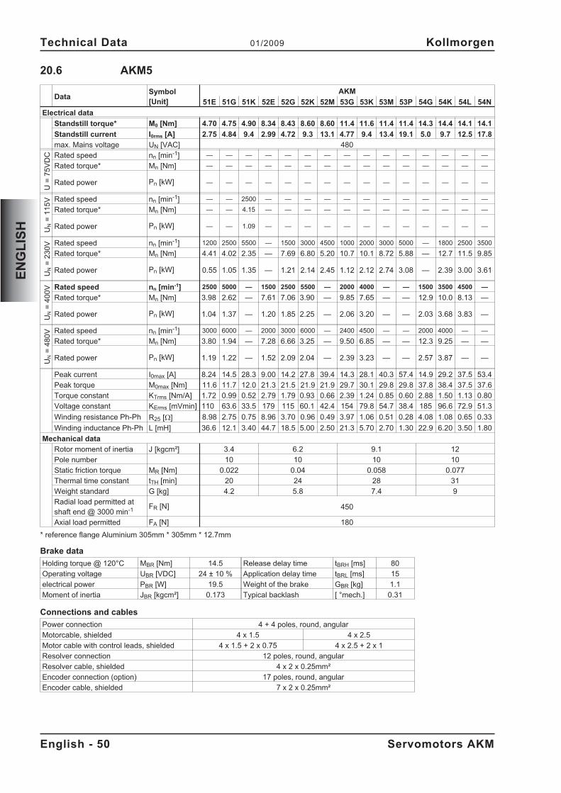
20.6 AKM5
DataSymbol[Unit]
AKM
51E 51G 51K 52E 52G 52K 52M 53G 53K 53M 53P 54G 54K 54L 54N
Electrical data
Standstill torque* M0 [Nm] 4.70 4.75 4.90 8.34 8.43 8.60 8.60 11.4 11.6 11.4 11.4 14.3 14.4 14.1 14.1
Standstill current I0rms [A] 2.75 4.84 9.4 2.99 4.72 9.3 13.1 4.77 9.4 13.4 19.1 5.0 9.7 12.5 17.8
max. Mains voltage UN [VAC] 480
U=
75
VD
C Rated speed nn [min-1] — — — — — — — — — — — — — — —
Rated torque* Mn [Nm] — — — — — — — — — — — — — — —
Rated power Pn [kW] — — — — — — — — — — — — — — —
UN
=1
15
V Rated speed nn [min-1] — — 2500 — — — — — — — — — — — —
Rated torque* Mn [Nm] — — 4.15 — — — — — — — — — — — —
Rated power Pn [kW] — — 1.09 — — — — — — — — — — — —
UN
=2
30
V Rated speed nn [min-1] 1200 2500 5500 — 1500 3000 4500 1000 2000 3000 5000 — 1800 2500 3500
Rated torque* Mn [Nm] 4.41 4.02 2.35 — 7.69 6.80 5.20 10.7 10.1 8.72 5.88 — 12.7 11.5 9.85
Rated power Pn [kW] 0.55 1.05 1.35 — 1.21 2.14 2.45 1.12 2.12 2.74 3.08 — 2.39 3.00 3.61
UN
=4
00
V Rated speed nn [min-1] 2500 5000 — 1500 2500 5500 — 2000 4000 — — 1500 3500 4500 —
Rated torque* Mn [Nm] 3.98 2.62 — 7.61 7.06 3.90 — 9.85 7.65 — — 12.9 10.0 8.13 —
Rated power Pn [kW] 1.04 1.37 — 1.20 1.85 2.25 — 2.06 3.20 — — 2.03 3.68 3.83 —
UN
=4
80
V Rated speed nn [min-1] 3000 6000 — 2000 3000 6000 — 2400 4500 — — 2000 4000 — —
Rated torque* Mn [Nm] 3.80 1.94 — 7.28 6.66 3.25 — 9.50 6.85 — — 12.3 9.25 — —
Rated power Pn [kW] 1.19 1.22 — 1.52 2.09 2.04 — 2.39 3.23 — — 2.57 3.87 — —
Peak current I0max [A] 8.24 14.5 28.3 9.00 14.2 27.8 39.4 14.3 28.1 40.3 57.4 14.9 29.2 37.5 53.4
Peak torque M0max [Nm] 11.6 11.7 12.0 21.3 21.5 21.9 21.9 29.7 30.1 29.8 29.8 37.8 38.4 37.5 37.6
Torque constant KTrms [Nm/A] 1.72 0.99 0.52 2.79 1.79 0.93 0.66 2.39 1.24 0.85 0.60 2.88 1.50 1.13 0.80
Voltage constant KErms [mVmin] 110 63.6 33.5 179 115 60.1 42.4 154 79.8 54.7 38.4 185 96.6 72.9 51.3
Winding resistance Ph-Ph R25 [] 8.98 2.75 0.75 8.96 3.70 0.96 0.49 3.97 1.06 0.51 0.28 4.08 1.08 0.65 0.33
Winding inductance Ph-Ph L [mH] 36.6 12.1 3.40 44.7 18.5 5.00 2.50 21.3 5.70 2.70 1.30 22.9 6.20 3.50 1.80
Mechanical data
Rotor moment of inertia J [kgcm²] 3.4 6.2 9.1 12
Pole number 10 10 10 10
Static friction torque MR [Nm] 0.022 0.04 0.058 0.077
Thermal time constant tTH [min] 20 24 28 31
Weight standard G [kg] 4.2 5.8 7.4 9
Radial load permitted atshaft end @ 3000 min-1 FR [N] 450
Axial load permitted FA [N] 180
* reference flange Aluminium 305mm * 305mm * 12.7mm
Brake data
Holding torque @ 120°C MBR [Nm] 14.5 Release delay time tBRH [ms] 80
Operating voltage UBR [VDC] 24 ± 10 % Application delay time tBRL [ms] 15
electrical power PBR [W] 19.5 Weight of the brake GBR [kg] 1.1
Moment of inertia JBR [kgcm²] 0.173 Typical backlash [ °mech.] 0.31
Connections and cables
Power connection 4 + 4 poles, round, angular
Motorcable, shielded 4 x 1.5 4 x 2.5
Motor cable with control leads, shielded 4 x 1.5 + 2 x 0.75 4 x 2.5 + 2 x 1
Resolver connection 12 poles, round, angular
Resolver cable, shielded 4 x 2 x 0.25mm²
Encoder connection (option) 17 poles, round, angular
Encoder cable, shielded 7 x 2 x 0.25mm²
English - 50 Servomotors AKM
Technical Data 01/2009 Kollmorgen
EN
GL
ISH
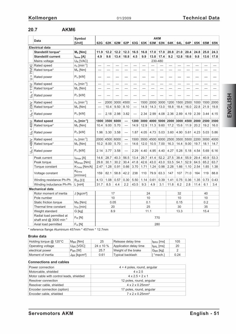
20.7 AKM6
DataSymbol[Unit]
AKM
62G 62K 62M 62P 63G 63K 63M 63N 64K 64L 64P 65K 65M 65N
Electrical data
Standstill torque* M0 [Nm] 11.9 12.2 12.2 12.3 16.5 16.8 17.0 17.0 20.8 21.0 20.4 24.8 25.0 24.3
Standstill current I0rms [A] 4.9 9.6 13.4 18.8 4.5 9.9 13.8 17.4 9.2 12.8 18.6 9.8 13.6 17.8
Mains voltage UN [VAC] 230-480
U=
75
VD
C Rated speed nn [min-1] — — — — — — — — — — — — — —
Rated torque* Mn [Nm] — — — — — — — — — — — — — —
Rated power Pn [kW] — — — — — — — — — — — — — —
UN
=1
15
V Rated speed nn [min-1] — — — — — — — — — — — — — —
Rated torque* Mn [Nm] — — — — — — — — — — — — — —
Rated power Pn [kW] — — — — — — — — — — — — — —
UN
=2
30
V Rated speed nn [min-1] — 2000 3000 4500 — 1500 2000 3000 1200 1500 2500 1000 1500 2000
Rated torque* Mn [Nm] — 10.4 9.50 8.10 — 14.9 14.3 13.0 18.8 18.4 16.0 22.8 21.9 19.8
Rated power Pn [kW] — 2.18 2.98 3.82 — 2.34 2.99 4.08 2.36 2.89 4.19 2.39 3.44 4.15
UN
=4
00
V Rated speed nn [min-1] 1800 3500 6000 — 1200 3000 4000 5000 2000 3000 4500 2000 2500 3500
Rated torque* Mn [Nm] 10.4 9.00 5.70 — 14.9 12.9 11.3 9.60 17.2 15.6 11.9 20.2 19.2 16.0
Rated power Pn [kW] 1.96 3.30 3.58 — 1.87 4.05 4.73 5.03 3.60 4.90 5.61 4.23 5.03 5.86
UN
=4
80
V Rated speed nn [min-1] 2000 4500 6000 — 1500 3500 4500 6000 2500 3500 5500 2200 3000 4000
Rated torque* Mn [Nm] 10.2 8.00 5.70 — 14.6 12.0 10.5 7.00 16.3 14.4 9.00 19.7 18.1 14.7
Rated power Pn [kW] 2.14 3.77 3.58 — 2.29 4.40 4.95 4.40 4.27 5.28 5.18 4.54 5.69 6.16
Peak current I0max [A] 14.6 28.7 40.3 56.5 13.4 29.7 41.4 52.2 27.5 38.4 55.9 29.4 40.9 53.3
Peak torque M0max [Nm] 29.8 30.1 30.2 30.4 41.8 42.6 43.0 43.0 53.5 54.1 52.9 64.5 65.2 63.7
Torque constant KTrms [Nm/A] 2.47 1.28 0.91 0.66 3.70 1.71 1.24 0.98 2.28 1.66 1.10 2.54 1.85 1.38
Voltage constantKErms
[mVmin]159 82.1 58.8 42.2 238 110 79.9 63.3 147 107 71.0 164 119 88.8
Winding resistance Ph-Ph R25 [] 4.13 1.08 0.57 0.30 5.50 1.14 0.61 0.39 1.41 0.75 0.36 1.35 0.73 0.43
Winding inductance Ph-Ph L [mH] 31.7 8.5 4.4 2.2 43.5 9.3 4.9 3.1 11.8 6.2 2.8 11.4 6.1 3.4
Mechanical data
Rotor moment of inertia J [kgcm²] 17 24 32 40
Pole number 10 10 10 10
Static friction torque MR [Nm] 0.05 0.1 0.15 0.2
Thermal time constant tTH [min] 20 25 30 35
Weight standard G [kg] 8.9 11.1 13.3 15.4
Radial load permitted atshaft end @ 3000 min-1 FR [N] 770
Axial load permitted FA [N] 280
* reference flange Aluminium 457mm * 457mm * 12.7mm
Brake data
Holding torque @ 120°C MBR [Nm] 25 Release delay time tBRH [ms] 105
Operating voltage UBR [VDC] 24 ± 10 % Application delay time tBRL [ms] 20
electrical power PBR [W] 25.7 Weight of the brake GBR [kg] 2
Moment of inertia JBR [kgcm²] 0.61 Typical backlash [ °mech.] 0.24
Connections and cables
Power connection 4 + 4 poles, round, angular
Motorcable, shielded 4 x 2.5
Motor cable with control leads, shielded 4 x 2.5 + 2 x 1
Resolver connection 12 poles, round, angular
Resolver cable, shielded 4 x 2 x 0.25mm²
Encoder connection (option) 17 poles, round, angular
Encoder cable, shielded 7 x 2 x 0.25mm²
Servomotors AKM English - 51
Kollmorgen 01/2009 Technical Data
EN
GL
ISH
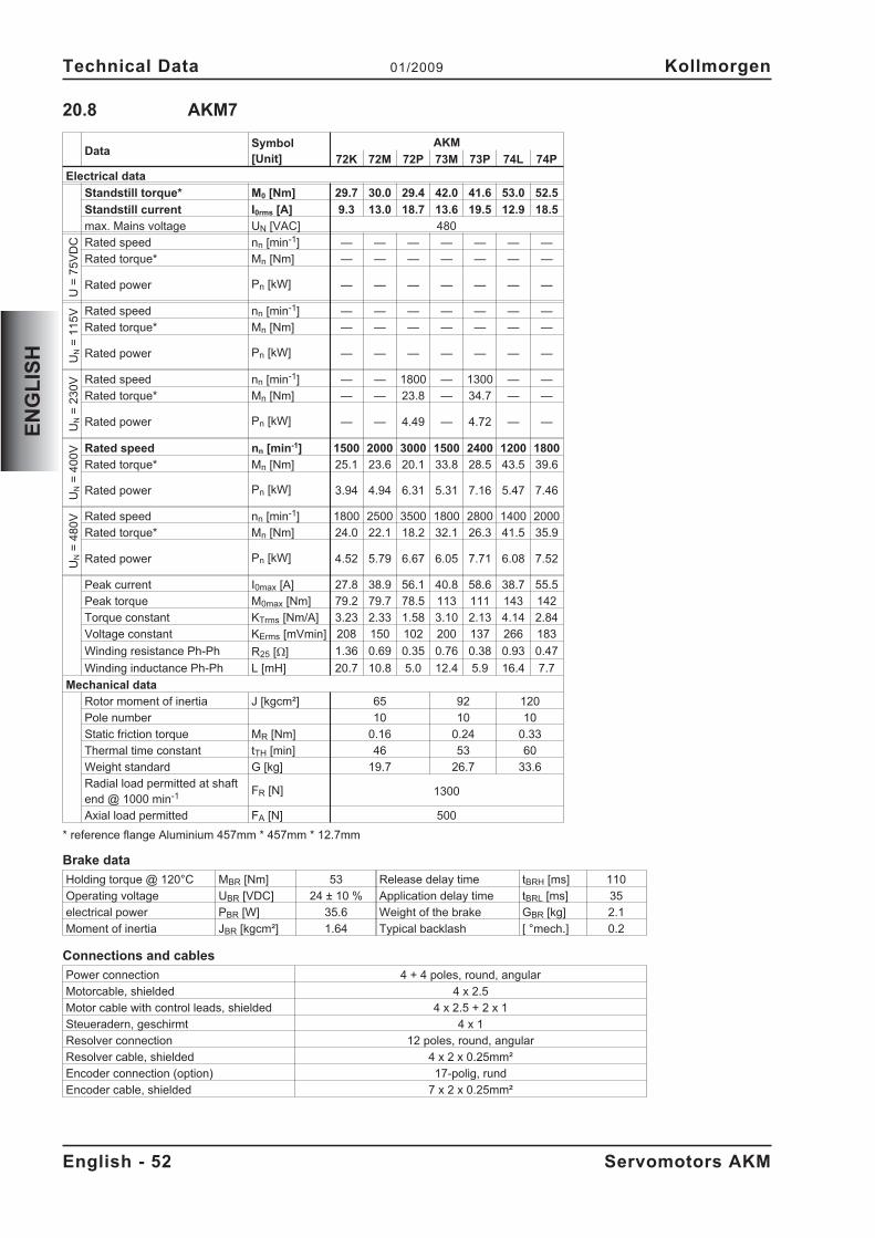
20.8 AKM7
DataSymbol[Unit]
AKM
72K 72M 72P 73M 73P 74L 74P
Electrical data
Standstill torque* M0 [Nm] 29.7 30.0 29.4 42.0 41.6 53.0 52.5
Standstill current I0rms [A] 9.3 13.0 18.7 13.6 19.5 12.9 18.5
max. Mains voltage UN [VAC] 480
U=
75
VD
C Rated speed nn [min-1] — — — — — — —
Rated torque* Mn [Nm] — — — — — — —
Rated power Pn [kW] — — — — — — —
UN
=1
15
V Rated speed nn [min-1] — — — — — — —
Rated torque* Mn [Nm] — — — — — — —
Rated power Pn [kW] — — — — — — —
UN
=2
30
V Rated speed nn [min-1] — — 1800 — 1300 — —
Rated torque* Mn [Nm] — — 23.8 — 34.7 — —
Rated power Pn [kW] — — 4.49 — 4.72 — —
UN
=4
00
V Rated speed nn [min-1] 1500 2000 3000 1500 2400 1200 1800
Rated torque* Mn [Nm] 25.1 23.6 20.1 33.8 28.5 43.5 39.6
Rated power Pn [kW] 3.94 4.94 6.31 5.31 7.16 5.47 7.46
UN
=4
80
V Rated speed nn [min-1] 1800 2500 3500 1800 2800 1400 2000
Rated torque* Mn [Nm] 24.0 22.1 18.2 32.1 26.3 41.5 35.9
Rated power Pn [kW] 4.52 5.79 6.67 6.05 7.71 6.08 7.52
Peak current I0max [A] 27.8 38.9 56.1 40.8 58.6 38.7 55.5
Peak torque M0max [Nm] 79.2 79.7 78.5 113 111 143 142
Torque constant KTrms [Nm/A] 3.23 2.33 1.58 3.10 2.13 4.14 2.84
Voltage constant KErms [mVmin] 208 150 102 200 137 266 183
Winding resistance Ph-Ph R25 [] 1.36 0.69 0.35 0.76 0.38 0.93 0.47
Winding inductance Ph-Ph L [mH] 20.7 10.8 5.0 12.4 5.9 16.4 7.7
Mechanical data
Rotor moment of inertia J [kgcm²] 65 92 120
Pole number 10 10 10
Static friction torque MR [Nm] 0.16 0.24 0.33
Thermal time constant tTH [min] 46 53 60
Weight standard G [kg] 19.7 26.7 33.6
Radial load permitted at shaftend @ 1000 min-1 FR [N] 1300
Axial load permitted FA [N] 500
* reference flange Aluminium 457mm * 457mm * 12.7mm
Brake data
Holding torque @ 120°C MBR [Nm] 53 Release delay time tBRH [ms] 110
Operating voltage UBR [VDC] 24 ± 10 % Application delay time tBRL [ms] 35
electrical power PBR [W] 35.6 Weight of the brake GBR [kg] 2.1
Moment of inertia JBR [kgcm²] 1.64 Typical backlash [ °mech.] 0.2
Connections and cables
Power connection 4 + 4 poles, round, angular
Motorcable, shielded 4 x 2.5
Motor cable with control leads, shielded 4 x 2.5 + 2 x 1
Steueradern, geschirmt 4 x 1
Resolver connection 12 poles, round, angular
Resolver cable, shielded 4 x 2 x 0.25mm²
Encoder connection (option) 17-polig, rund
Encoder cable, shielded 7 x 2 x 0.25mm²
English - 52 Servomotors AKM
Technical Data 01/2009 Kollmorgen
EN
GL
ISH
21 Indicazoni generali
21.1 Questo manuale
Questo manuale descrive i servomotori sincroni della serie AKM (versione standard).
Se i motori vengono utilizzati in un sistema di azionamento insieme ai servoamplificatoriKollmorgen. Attenersi pertanto alla documentazione dei prodotti composta da:
— manuale del prodotto del servoamplificatore— istruzioni per l'installazione/la messa in funzione di una scheda di espansione— eventualmente presente— aiuto in linea del software operativo del servoamplificatore— manuale degli accessori— descrizione tecnica dei motori serie AKM
21.2 Gruppo di obiettivo
Questo manuale è rivolto a personale con le seguenti qualifiche:Trasporto: solo a cura di personale con nozioni di movimentazione
componenti sensibili alle cariche elettrostatiche.Installazione mecc.: solo da parte di meccanicai specializzatiInstallazione elett.: solo a cura di elettricisti qualificati.Configurazione: solo a cura di personale qualificato con nozioni approfondite in
materia di elettrotecnica e tecnologia di azionamento.Il personale tecnico deve conoscere e osservare le seguenti norme e direttive:
I.C. 60364 o I.C. 60664disposizioni antinfortunistiche nazionali
L’operatore deve accertarsi che le istruzioni di sicurezza in questo manuale siano seguite.L’operatore deve accertarsi che tutti i personali responsabili del funzionamento con motoreabbiano letto e capito il manuale del prodotto.
21.3 Simboli utilizzati
Rischio di infortunio dovuto all’elettricità eai suoi effetti
Pericolo generaleInformazioni generaliRischio meccanico
�Vedere capitolo/pagina(riferimento incrociato)
� Nota
21.4 Abbreviazioni utilizzati
Veda il capitolo 30.1 "Definizioni".
Servomotori AKM Italiano - 53
Kollmorgen 01/2009 Indicazoni generali
ITA
LIA
NO
22 Sicurezza
22.1 Indicazioni di sicurezza
� I lavori di trasporto, montaggio, messa in funzione e manutenzione si possono affida-re esclusivamente a personale tecnico qualificato, che abbia familiarità con il traspor-to, l'installazione, il montaggio, la messa in funzione e il funzionamento dei motori eche disponga di opportune qualifiche per lo svolgimento di tali attività. Il personaletecnico deve conoscere e osservare le seguenti norme e direttive:
IEC 60364 o IEC 60664disposizioni antinfortunistiche nazionali
� Prima di procedere al montaggio e alla messa in funzione leggere la presente docu-mentazione. L'errata manipolazione del motore può comportare danni a persone o acose. Osservare assolutamente i dati tecnici e le indicazioni sulle condizioni di colle-gamento (targhetta di omologazione e documentazione).
� Il produttore è tenuto a realizzare un'analisi dei rischi per il macchinario e ad adottarele misure necessarie, affinché eventuali movimenti imprevisti non causino danni apersone o a cose.
� Assicurare la regolare messa a terra della carcassa del motore con la bandella PEall'interno dell'armadio di distribuzione come potenziale di riferimento. Senza unamessa a terra a bassa impedenza non viene garantita alcuna sicurezza alle persone.
� Non scollegare nessun connettore durante il funzionamento. Sussiste il pericolo dimorte, di seri infortuni o danni materiali.
� I collegamenti di potenza possono condurre tensione anche a motore fermo. Non al-lentare mai i collegamenti elettrici dei motori sotto tensione. In casi sfavorevoli pos-sono venire a crearsi archi voltaici con conseguenti danni a carico di persone e cose.
� Dopo aver scollegato i servoamplificatori dalle tensioni di alimentazione attendere al-meno cinque minuti prima di toccare i componenti sotto tensione (ad esempio contat-ti, perni filettati) o di allentare collegamenti. I condensatori nel servoamplificatoreconducono tensioni pericolose fino a cinque minuti dopo la disinserzione delle ten-sioni di alimentazione. Per sicurezza, misurare la tensione nel circuito intermedio eattendere fino a quando il valore è sceso al di sotto dei 40V.
� Durante il funzionamento i motori possono presentare superfici calde a seconda delloro grado di protezione. La temperatura superficiale può varcare i 100°C. Misurare latemperatura e attendere che il motore abbia raggiunto i 40°C prima di toccarlo.
� Se il motore ruota liberamente rimuovere/fissare l'eventuale chiavetta dell'albero perevitarne l'espulsione con conseguente pericolo di lesioni.
Italiano - 54 Servomotori AKM
Sicurezza 01/2009 Kollmorgen
ITA
LIA
NO
22.2 Uso conforme
� I servomotori sincroni della serie AKM sono stati concepiti in modo particolare come aziona-mento per dispositivi di movimentazione, macchine tessili, macchine utensili, confezionatricie simili con elevati requisiti in termini di dinamica.
� Azionare i motori solo nel rispetto delle condizioni stabilite nella presente documentazione.
� I motori della serie AKM sono esclusivamente destinati ad essere comandati da servoam-plificatori digitali con regolazione della velocità e/o della coppia.
� I motori vengono montati come componenti su impianti o macchine elettrici e possono ess-ere messi in funzione solo come componenti integrati dell'impianto.
� Si richiedono l'analisi e il monitoraggio del termocontatto di protezione montato negli avvolgi-menti del motore.
� Garantiamo la conformità del servosistema alle norme menzionate nella EC Declaration ofConformity a pagina 56 solo se vengono utilizzati componenti originali (servoamplificatori,motore, cavi, e così via).
22.3 Uso conforme vietato
� È vietato l’uso del motor nei seguenti ambienti:- aree a rischio di esplosione- ambienti caratterizzati dalla presenza di acidi, soluzioni alcaline, oli, vapori, polveri
corrosivi e/o conduttivi- direttamente su reti elettriche
� L’uso conforme del motore è vietato quando la macchina cui è destinato- non è conforme alle disposizioni della Direttiva Macchine- non soddisfa le disposizioni della Direttiva sulla Compatibilità Elettromagnetica- non soddisfa le disposizioni della Direttiva Bassa Tensione
Servomotori AKM Italiano - 55
Kollmorgen 01/2009 Sicurezza
ITA
LIA
NO
23 Norme validi
23.1 EC Declaration of Conformity
We, the company
Danaher Motion GmbHWacholderstrasse 40-4240489 Düsseldorf
hereby in sole responsibility declare the conformity of the product series
Motor series AKM(Types AKM1, AKM2, AKM3, AKM4, AKM5, AKM6, AKM7)
with the following standards:
- EC Directive 2004/108/ECElectromagnetic compatibilityUsed standard EN61800-3:07/2005
- EC Directive 2006/95/ECElectrical devices for use in special voltage limitsUsed standards
EN60034-1:1998+A1+A2+A3EN60034-5:2001EN60529:1991+A1EN61800-5-1:04/2008
Year of EC-Declaration 2003
Issued by: Product Manager Motors Europe
Jörg Peters
Düsseldorf, 06.01.2009
Legally valid signature
This Declaration does not contain any assurance of properties in the meaning of product liability.The notes on safety and protection in the operating instructions must always be observed.The above-mentioned company has the following technical documentation for examination:- Proper operating instructions- Diagrams (for EU authority only)- Test certificates (for EU authority only)- Other technical documentation (for EU authority only)
Italiano - 56 Servomotori AKM
Norme validi 01/2009 Kollmorgen
ITA
LIA
NO
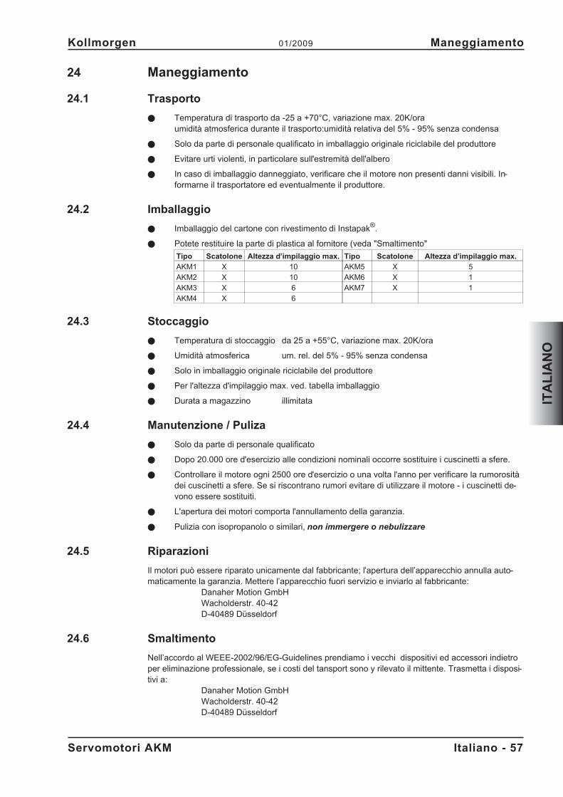
24 Maneggiamento
24.1 Trasporto
� Temperatura di trasporto da -25 a +70°C, variazione max. 20K/oraumidità atmosferica durante il trasporto:umidità relativa del 5% - 95% senza condensa
� Solo da parte di personale qualificato in imballaggio originale riciclabile del produttore
� Evitare urti violenti, in particolare sull'estremità dell'albero
� In caso di imballaggio danneggiato, verificare che il motore non presenti danni visibili. In-formarne il trasportatore ed eventualmente il produttore.
24.2 Imballaggio
� Imballaggio del cartone con rivestimento di Instapak®.
� Potete restituire la parte di plastica al fornitore (veda "Smaltimento"
Tipo Scatolone Altezza d’impilaggio max. Tipo Scatolone Altezza d’impilaggio max.
AKM1 X 10 AKM5 X 5
AKM2 X 10 AKM6 X 1
AKM3 X 6 AKM7 X 1
AKM4 X 6
24.3 Stoccaggio
� Temperatura di stoccaggio da 25 a +55°C, variazione max. 20K/ora
� Umidità atmosferica um. rel. del 5% - 95% senza condensa
� Solo in imballaggio originale riciclabile del produttore
� Per l'altezza d'impilaggio max. ved. tabella imballaggio
� Durata a magazzino illimitata
24.4 Manutenzione / Puliza
� Solo da parte di personale qualificato
� Dopo 20.000 ore d'esercizio alle condizioni nominali occorre sostituire i cuscinetti a sfere.
� Controllare il motore ogni 2500 ore d'esercizio o una volta l'anno per verificare la rumorositàdei cuscinetti a sfere. Se si riscontrano rumori evitare di utilizzare il motore - i cuscinetti de-vono essere sostituiti.
� L'apertura dei motori comporta l'annullamento della garanzia.
� Pulizia con isopropanolo o similari, non immergere o nebulizzare
24.5 Riparazioni
Il motori può essere riparato unicamente dal fabbricante; l’apertura dell’apparecchio annulla auto-maticamente la garanzia. Mettere l’apparecchio fuori servizio e inviarlo al fabbricante:
Danaher Motion GmbHWacholderstr. 40-42D-40489 Düsseldorf
24.6 Smaltimento
Nell’accordo al WEEE-2002/96/EG-Guidelines prendiamo i vecchi dispositivi ed accessori indietroper eliminazione professionale, se i costi del tansport sono y rilevato il mittente. Trasmetta i disposi-tivi a:
Danaher Motion GmbHWacholderstr. 40-42D-40489 Düsseldorf
Servomotori AKM Italiano - 57
Kollmorgen 01/2009 Maneggiamento
ITA
LIA
NO
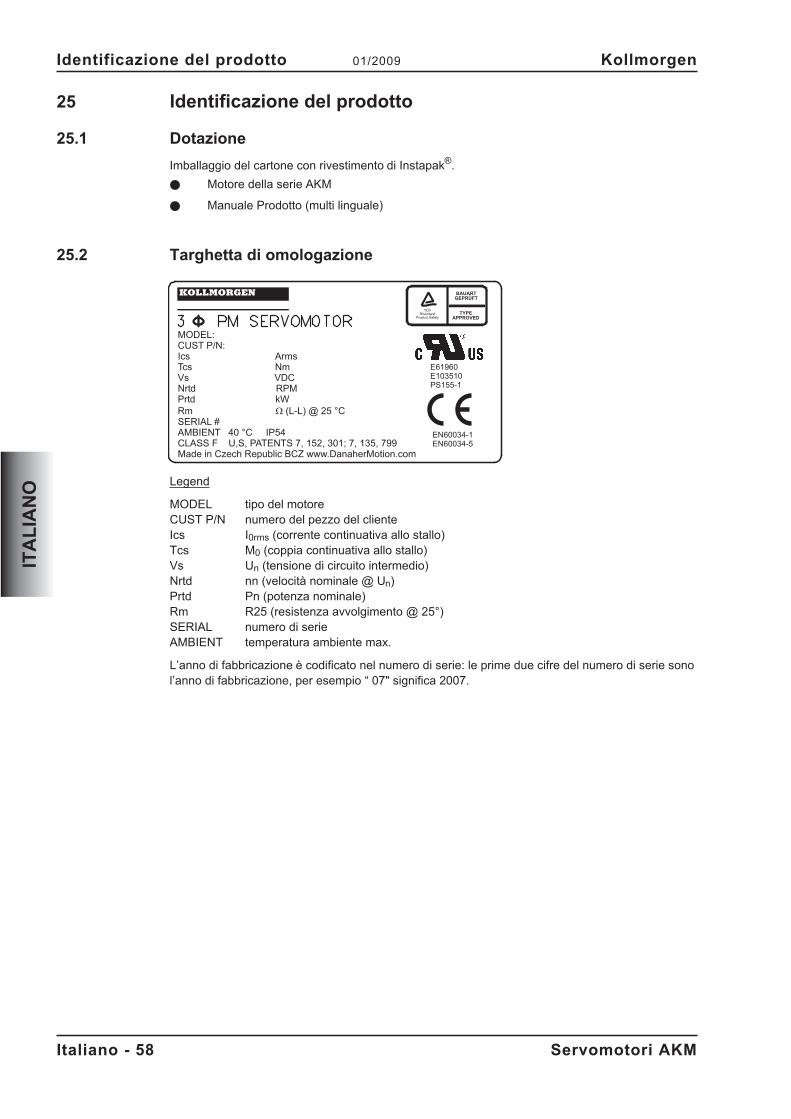
25 Identificazione del prodotto
25.1 Dotazione
Imballaggio del cartone con rivestimento di Instapak®.
� Motore della serie AKM
� Manuale Prodotto (multi linguale)
25.2 Targhetta di omologazione
Legend
MODEL tipo del motoreCUST P/N numero del pezzo del clienteIcs I0rms (corrente continuativa allo stallo)Tcs M0 (coppia continuativa allo stallo)Vs Un (tensione di circuito intermedio)Nrtd nn (velocità nominale @ Un)Prtd Pn (potenza nominale)Rm R25 (resistenza avvolgimento @ 25°)SERIAL numero di serieAMBIENT temperatura ambiente max.
L’anno di fabbricazione è codificato nel numero di serie: le prime due cifre del numero di serie sonol’anno di fabbricazione, per esempio “ 07" significa 2007.
Italiano - 58 Servomotori AKM
Identificazione del prodotto 01/2009 Kollmorgen
ITA
LIA
NO
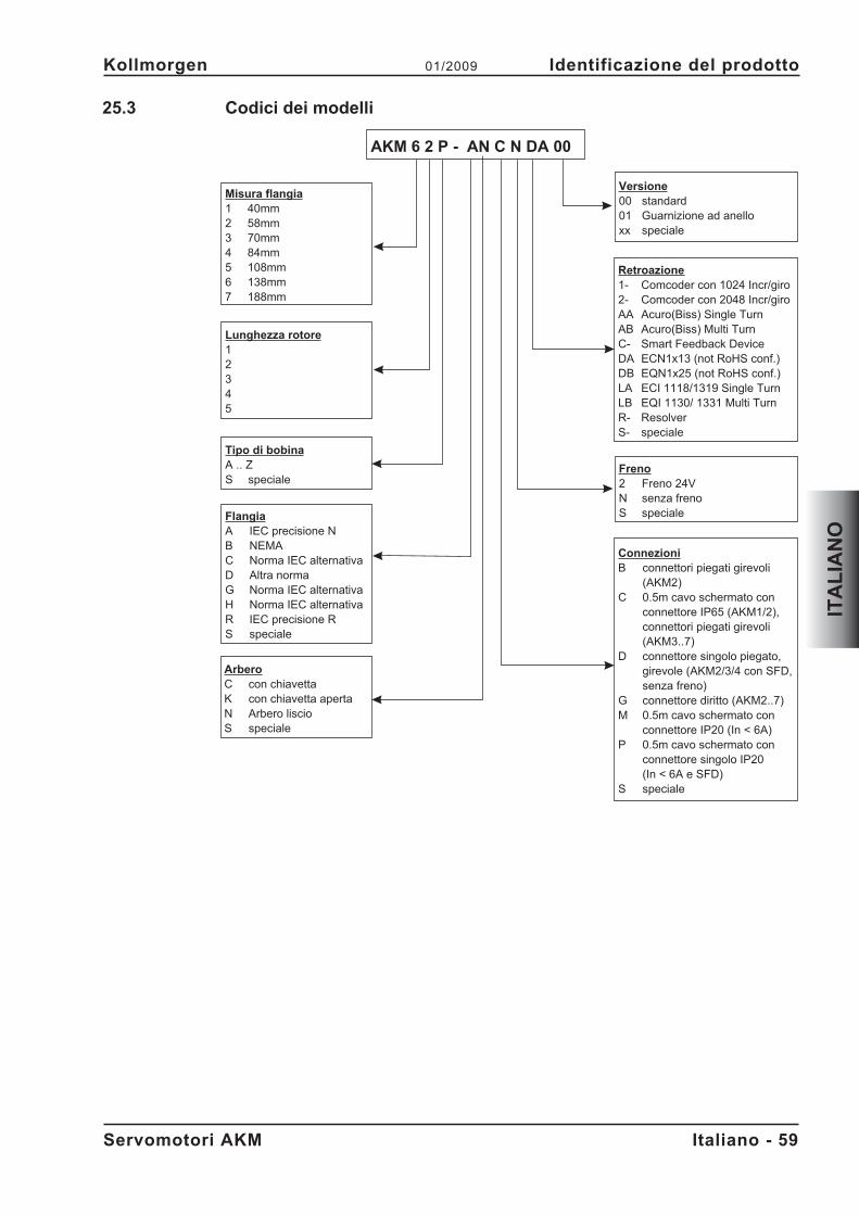
25.3 Codici dei modelli
Servomotori AKM Italiano - 59
Kollmorgen 01/2009 Identificazione del prodotto
ITA
LIA
NO
Misura flangia1 40mm2 58mm3 70mm4 84mm5 108mm6 138mm7 188mm
FlangiaA IEC precisione NB NEMAC Norma IEC alternativaD Altra normaG Norma IEC alternativaH Norma IEC alternativaR IEC precisione RS speciale
Lunghezza rotore12345
Tipo di bobinaA .. ZS speciale
ConnezioniB connettori piegati girevoli
(AKM2)C 0.5m cavo schermato con
connettore IP65 (AKM1/2),connettori piegati girevoli(AKM3..7)
D connettore singolo piegato,girevole (AKM2/3/4 con SFD,senza freno)
G connettore diritto (AKM2..7)M 0.5m cavo schermato con
connettore IP20 (In < 6A)P 0.5m cavo schermato con
connettore singolo IP20(In < 6A e SFD)
S speciale
Freno2 Freno 24VN senza frenoS speciale
Retroazione1- Comcoder con 1024 Incr/giro2- Comcoder con 2048 Incr/giroAA Acuro(Biss) Single TurnAB Acuro(Biss) Multi TurnC- Smart Feedback DeviceDA ECN1x13 (not RoHS conf.)DB EQN1x25 (not RoHS conf.)LA ECI 1118/1319 Single TurnLB EQI 1130/ 1331 Multi TurnR- ResolverS- speciale
Versione00 standard01 Guarnizione ad anelloxx speciale
AKM 6 2 P - AN C N DA 00
ArberoC con chiavettaK con chiavetta apertaN Arbero liscioS speciale
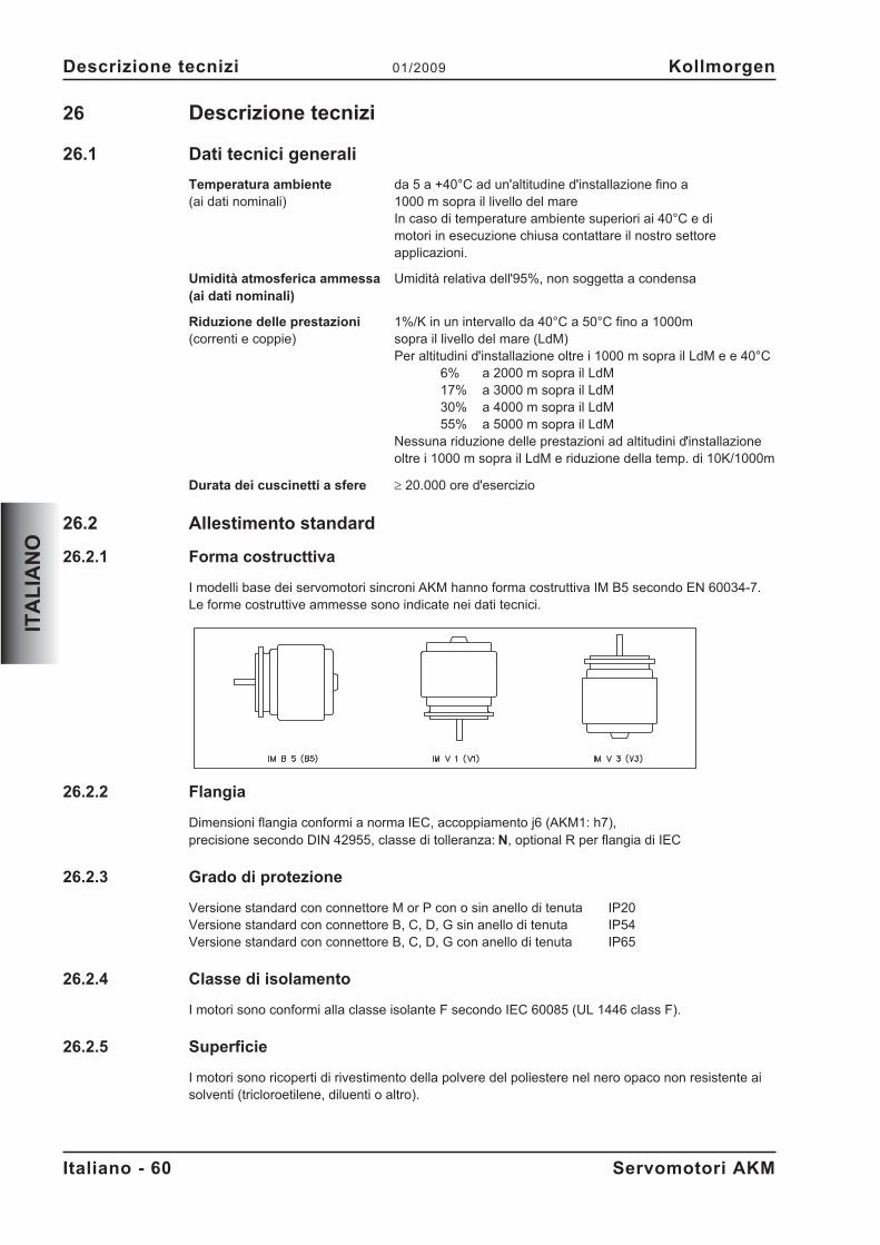
26 Descrizione tecnizi
26.1 Dati tecnici generali
Temperatura ambiente da 5 a +40°C ad un'altitudine d'installazione fino a(ai dati nominali) 1000 m sopra il livello del mare
In caso di temperature ambiente superiori ai 40°C e dimotori in esecuzione chiusa contattare il nostro settoreapplicazioni.
Umidità atmosferica ammessa Umidità relativa dell'95%, non soggetta a condensa(ai dati nominali)
Riduzione delle prestazioni 1%/K in un intervallo da 40°C a 50°C fino a 1000m(correnti e coppie) sopra il livello del mare (LdM)
Per altitudini d'installazione oltre i 1000 m sopra il LdM e e 40°C6% a 2000 m sopra il LdM17% a 3000 m sopra il LdM30% a 4000 m sopra il LdM55% a 5000 m sopra il LdM
Nessuna riduzione delle prestazioni ad altitudini d'installazioneoltre i 1000 m sopra il LdM e riduzione della temp. di 10K/1000m
Durata dei cuscinetti a sfere � 20.000 ore d'esercizio
26.2 Allestimento standard
26.2.1 Forma costructtiva
I modelli base dei servomotori sincroni AKM hanno forma costruttiva IM B5 secondo EN 60034-7.Le forme costruttive ammesse sono indicate nei dati tecnici.
26.2.2 Flangia
Dimensioni flangia conformi a norma IEC, accoppiamento j6 (AKM1: h7),precisione secondo DIN 42955, classe di tolleranza: N, optional R per flangia di IEC
26.2.3 Grado di protezione
Versione standard con connettore M or P con o sin anello di tenuta IP20Versione standard con connettore B, C, D, G sin anello di tenuta IP54Versione standard con connettore B, C, D, G con anello di tenuta IP65
26.2.4 Classe di isolamento
I motori sono conformi alla classe isolante F secondo IEC 60085 (UL 1446 class F).
26.2.5 Superficie
I motori sono ricoperti di rivestimento della polvere del poliestere nel nero opaco non resistente aisolventi (tricloroetilene, diluenti o altro).
Italiano - 60 Servomotori AKM
Descrizione tecnizi 01/2009 Kollmorgen
ITA
LIA
NO
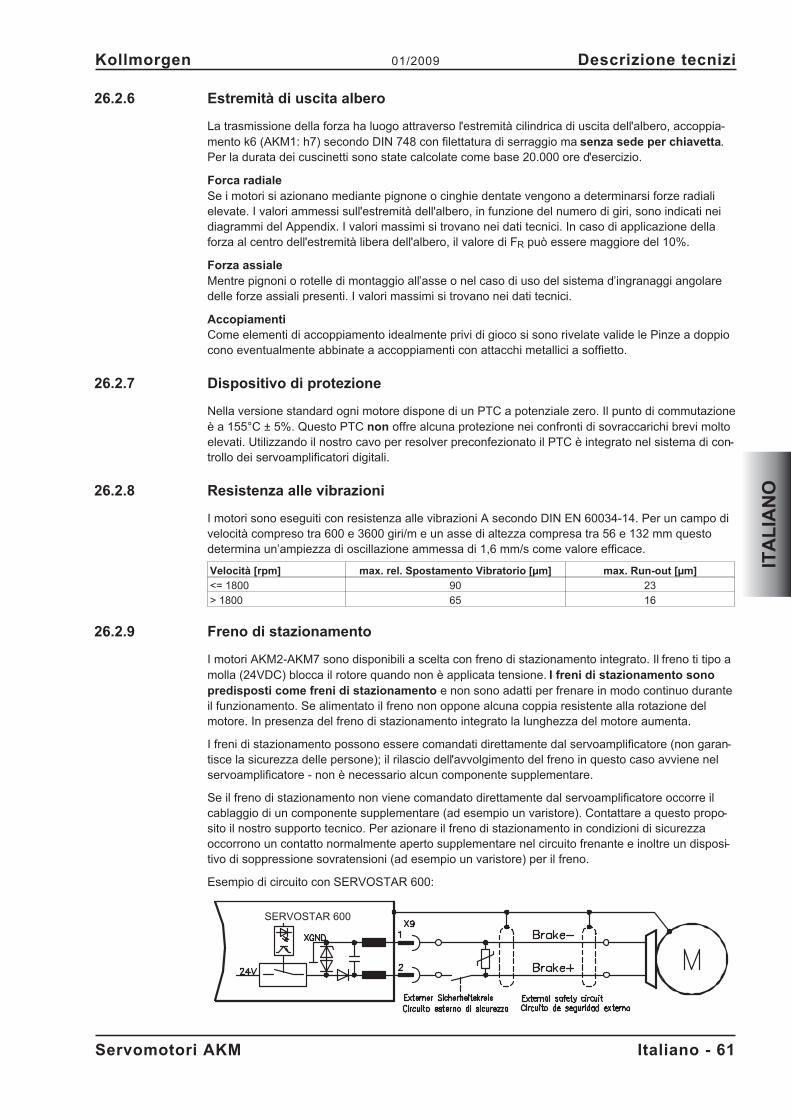
26.2.6 Estremità di uscita albero
La trasmissione della forza ha luogo attraverso l'estremità cilindrica di uscita dell'albero, accoppia-mento k6 (AKM1: h7) secondo DIN 748 con filettatura di serraggio ma senza sede per chiavetta.Per la durata dei cuscinetti sono state calcolate come base 20.000 ore d'esercizio.
Forca radialeSe i motori si azionano mediante pignone o cinghie dentate vengono a determinarsi forze radialielevate. I valori ammessi sull'estremità dell'albero, in funzione del numero di giri, sono indicati neidiagrammi del Appendix. I valori massimi si trovano nei dati tecnici. In caso di applicazione dellaforza al centro dell'estremità libera dell'albero, il valore di FR può essere maggiore del 10%.
Forza assialeMentre pignoni o rotelle di montaggio all’asse o nel caso di uso del sistema d’ingranaggi angolaredelle forze assiali presenti. I valori massimi si trovano nei dati tecnici.
AccopiamentiCome elementi di accoppiamento idealmente privi di gioco si sono rivelate valide le Pinze a doppiocono eventualmente abbinate a accoppiamenti con attacchi metallici a soffietto.
26.2.7 Dispositivo di protezione
Nella versione standard ogni motore dispone di un PTC a potenziale zero. Il punto di commutazioneè a 155°C ± 5%. Questo PTC non offre alcuna protezione nei confronti di sovraccarichi brevi moltoelevati. Utilizzando il nostro cavo per resolver preconfezionato il PTC è integrato nel sistema di con-trollo dei servoamplificatori digitali.
26.2.8 Resistenza alle vibrazioni
I motori sono eseguiti con resistenza alle vibrazioni A secondo DIN EN 60034-14. Per un campo divelocità compreso tra 600 e 3600 giri/m e un asse di altezza compresa tra 56 e 132 mm questodetermina un’ampiezza di oscillazione ammessa di 1,6 mm/s come valore efficace.
Velocità [rpm] max. rel. Spostamento Vibratorio [µm] max. Run-out [µm]
<= 1800 90 23
> 1800 65 16
26.2.9 Freno di stazionamento
I motori AKM2-AKM7 sono disponibili a scelta con freno di stazionamento integrato. Il freno ti tipo amolla (24VDC) blocca il rotore quando non è applicata tensione. I freni di stazionamento sonopredisposti come freni di stazionamento e non sono adatti per frenare in modo continuo duranteil funzionamento. Se alimentato il freno non oppone alcuna coppia resistente alla rotazione delmotore. In presenza del freno di stazionamento integrato la lunghezza del motore aumenta.
I freni di stazionamento possono essere comandati direttamente dal servoamplificatore (non garan-tisce la sicurezza delle persone); il rilascio dell'avvolgimento del freno in questo caso avviene nelservoamplificatore - non è necessario alcun componente supplementare.
Se il freno di stazionamento non viene comandato direttamente dal servoamplificatore occorre ilcablaggio di un componente supplementare (ad esempio un varistore). Contattare a questo propo-sito il nostro supporto tecnico. Per azionare il freno di stazionamento in condizioni di sicurezzaoccorrono un contatto normalmente aperto supplementare nel circuito frenante e inoltre un disposi-tivo di soppressione sovratensioni (ad esempio un varistore) per il freno.
Esempio di circuito con SERVOSTAR 600:
Servomotori AKM Italiano - 61
Kollmorgen 01/2009 Descrizione tecnizi
ITA
LIA
NO
SERVOSTAR 600
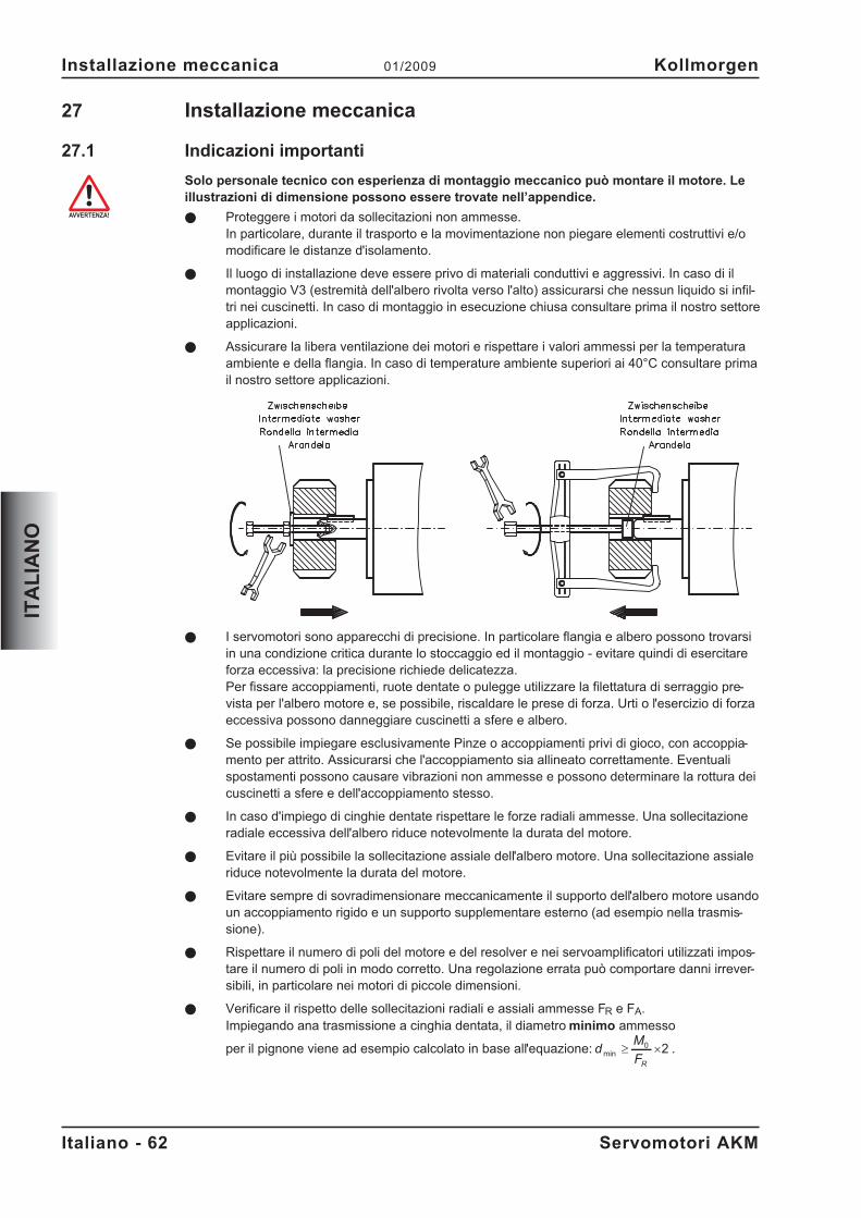
27 Installazione meccanica
27.1 Indicazioni importanti
Solo personale tecnico con esperienza di montaggio meccanico può montare il motore. Leillustrazioni di dimensione possono essere trovate nell’appendice.
� Proteggere i motori da sollecitazioni non ammesse.In particolare, durante il trasporto e la movimentazione non piegare elementi costruttivi e/omodificare le distanze d'isolamento.
� Il luogo di installazione deve essere privo di materiali conduttivi e aggressivi. In caso di ilmontaggio V3 (estremità dell'albero rivolta verso l'alto) assicurarsi che nessun liquido si infil-tri nei cuscinetti. In caso di montaggio in esecuzione chiusa consultare prima il nostro settoreapplicazioni.
� Assicurare la libera ventilazione dei motori e rispettare i valori ammessi per la temperaturaambiente e della flangia. In caso di temperature ambiente superiori ai 40°C consultare primail nostro settore applicazioni.
� I servomotori sono apparecchi di precisione. In particolare flangia e albero possono trovarsiin una condizione critica durante lo stoccaggio ed il montaggio - evitare quindi di esercitareforza eccessiva: la precisione richiede delicatezza.Per fissare accoppiamenti, ruote dentate o pulegge utilizzare la filettatura di serraggio pre-vista per l'albero motore e, se possibile, riscaldare le prese di forza. Urti o l'esercizio di forzaeccessiva possono danneggiare cuscinetti a sfere e albero.
� Se possibile impiegare esclusivamente Pinze o accoppiamenti privi di gioco, con accoppia-mento per attrito. Assicurarsi che l'accoppiamento sia allineato correttamente. Eventualispostamenti possono causare vibrazioni non ammesse e possono determinare la rottura deicuscinetti a sfere e dell'accoppiamento stesso.
� In caso d'impiego di cinghie dentate rispettare le forze radiali ammesse. Una sollecitazioneradiale eccessiva dell'albero riduce notevolmente la durata del motore.
� Evitare il più possibile la sollecitazione assiale dell'albero motore. Una sollecitazione assialeriduce notevolmente la durata del motore.
� Evitare sempre di sovradimensionare meccanicamente il supporto dell'albero motore usandoun accoppiamento rigido e un supporto supplementare esterno (ad esempio nella trasmis-sione).
� Rispettare il numero di poli del motore e del resolver e nei servoamplificatori utilizzati impos-tare il numero di poli in modo corretto. Una regolazione errata può comportare danni irrever-sibili, in particolare nei motori di piccole dimensioni.
� Verificare il rispetto delle sollecitazioni radiali e assiali ammesse FR e FA.Impiegando ana trasmissione a cinghia dentata, il diametro minimo ammesso
per il pignone viene ad esempio calcolato in base all'equazione: dM
FR
min � �0 2 .
Italiano - 62 Servomotori AKM
Installazione meccanica 01/2009 Kollmorgen
ITA
LIA
NO
28 Installazione elettrica
28.1 Indicazioni di sicurezza
Solo personale tecnico con esperienza nei collegamenti elettrici può cablare il motore. Glischemi elettrici possono essere trovati nell’appendice.
Montare e cablare i motori sempre in assenza di tensione, vale a dire senza inserire la ten-sione d'esercizio degli apparecchi da collegare. Assicurarsi che il quadro elettrico vengadisinserito in modo sicuro (blocco, cartelli di avvertenza, e così via). Le singole tensioni ver-ranno inserite solo con la messa in funzione.
Non allentare mai i collegamenti elettrici dei motori sotto tensione. Le cariche residue neicondensatori del servoamplificatore possono presentare valori pericolosi anche fino a 5 mi-nuti dopo la disinserzione della tensione di rete. Misurare la tensione nel circuito intermedioe attendere fino a quando il valore è sceso al di sotto dei 40V. I collegamenti di comando e dipotenza possono condurre tensione anche a motore fermo.
Il simbolo messa a terra� che si trova in tutti gli schemi di collegamento indica che oc-corre provvedere ad un collegamento conduttivo il più ampio possibile tra l'apparecchioidentificato e la piastra di montaggio nel quadro elettrico ad armadio. Tale collegamentodeve consentire la dispersione di interferenze ad alta frequenza e non deve essere confusocon il simbolo di terra PE (misura di protezione secondo EN 60204).Osservare anche le note negli schemi di collegamento delle manuale del prodotto del servo-amplificatore utilizzato.
28.2 Guida ad installazione elettrica
� Verificare l'abbinamento tra servoamplificatori e motore. Confrontare la tensione nominale ela corrente nominale degli apparecchi. Eseguire il cablaggio in base allo schema di collega-mento riportato sul manuale del servoamplificatore. I collegamenti del motore sono indicatida Appendix.
� Assicurarsi che la messa a terra di servoamplificatore e motore venga eseguita a regolad'arte. Per una schermatura e una messa a terra conformi ai requisiti di compatibilità elettro-magnetica si vedano le manuale del servoamplificatore utilizzato. Collegare a terra la piastradi montaggio e la carcassa del motore.
� Se possibile, posare separatamente cavi di potenza e di comando (distanza > 20 cm). Lacompatibilità elettromagnetica del sistema viene così migliorata. Se il cavo di potenza impie-gato per il motore integra i conduttori di comando del freno questi ultimi devono essereschermati. La schermatura deve essere collegata su entrambe le estremità (vedere le istru-zioni per l'installazione del servoamplificatore).
� Cablaggio— Se possibile, posare separatamente i cavi di potenza e di comando— Collegare l'unità di retroazione o encoder— Collegare i cavi del motore, l'induttore per motore vicino al Servoamplificatore— le schermature, su entrambe le estremità, ai morsetti o ai connettori EMC— Collegare l'eventuale il freno di stazionamento del motore.— Posare la schermatura su entrambi i lati
� Tutti i cavi che conducono correnti elevate devono avere sezione sufficiente secondoEN 30204. Le sezioni consigliate sono indicate nei dati tecnici.Nel caso del motore lungo cavo (>25m) ed il dipendente sul tipo del servoamplificato-re utilizzato una scatola induttore (3YL) deve essere commutato nel cavo del motore(veda il manuale del prodotto del servoamplificatore ed il manuale accessorio).
� Collegare le schermature in modo da coprire un'ampia superficie (a bassa impedenza), me-diante un corpo connettore metallizzato o connettori filettati per cavi conformi ai requisiti sul-la compatibilità elettromagnetica.
Servomotori AKM Italiano - 63
Kollmorgen 01/2009 Installazione elettrica
ITA
LIA
NO
28.3 Collegamento dei motori
� Eseguire il cablaggio in base alle disposizioni ed alle norme vigenti. Gli schemi elettri-ci possono essere trovati nell’appendice.
� Per il collegamento di potenza e di retroazione utilizzare esclusivamente i nostri cavischermati preconfezionati.
� Posare le schermature in base agli schemi di collegamento riportati nelle istruzioniper l'installazione dei servoamplificatori.
� Le schermature non posate correttamente comportano immancabilmente disturbielettromagnetici.
� Lunghezza dei cavi max.: attenersi manuali d'installazione del servoamplificatore
Requisiti a materiale dei cavi:
Capacità
Cavo di motore - inferiore a 150 pF/mCavo die retroazione - inferiore a 120 pF/m
Per la descrizione dettagliata dei cavie confezionamento consultare il manuale degli acces-sori.
Italiano - 64 Servomotori AKM
Installazione elettrica 01/2009 Kollmorgen
ITA
LIA
NO
29 Messa in funzione
29.1 Indicazioni importanti
Solo tecnici con ampie conoscenze di elettrotecnica/tecniche di movimentazione possonomettere in funzione l'unità di azionamento con servoamplificatore/motore.
Verificare che tutti gli elementi di collegamento sotto tensione siano protetti in modo sicurocontro il contatto. Presenza di tensioni letali fino a 900V.
Non allentare mai i collegamenti elettrici dei motori sotto tensione. Le cariche residue neicondensatori dei servoamplificatori possono essere pericolose fino a 5 minuti dopo la disin-serzione della tensione di rete.
La temperatura superficiale del motore può varcare i 100°C durante il funzionamento. Verifi-care (misurare) la temperatura del motore. Prima di toccarlo attendere che abbia raggiunto i40°C.
Assicurarsi che anche in caso di spostamento accidentale dell'azionamento non possa sus-sistere alcun pericolo per la macchina o le persone.
29.2 Guida ad messa in funzione
A titolo di esempio descriviamo la procedura da seguire per la messa in funzione.A seconda dell'impiego previsto può risultare opportuna o necessaria una procedura diversa.
� Controllare il montaggio e l'orientamento del motore.
� Verificare che gli elementi di azionamento (accoppiamento, trasmissione, puleggia) siano fis-sati nella relativa sede e che siano regolati correttamente (rispettare le forze radiali e assialiammesse).
� Controllare il cablaggio e i collegamenti su motore e servoamplificatore. Assicurarsi che lamessa a terra venga effettuata a regola d'arte.
� Controllare il funzionamento dell'eventuale freno di stazionamento. (Applicando 24V il frenodeve essere rilasciarsi).
� Verificare se il rotore del motore può ruotare liberamente (rilasciare prima l'eventuale freno).Prestare attenzione ai rumori di sfregamento.
� Verificare che siano state adottate tutte le misure di protezione dal contatto necessarie per icomponenti mobili e sotto tensione.
� Eseguire gli ulteriori controlli specifici e necessari per l'impianto in uso.
� Mettere in funzione l'azionamento in base alle istruzioni per la messa in funzione del servo-amplificatore.
� In caso di sistemi multiasse mettere in funzione ogni unità di azionamento del servoamplifi-catore/motore singolarmente.
Servomotori AKM Italiano - 65
Kollmorgen 01/2009 Messa in funzione
ITA
LIA
NO
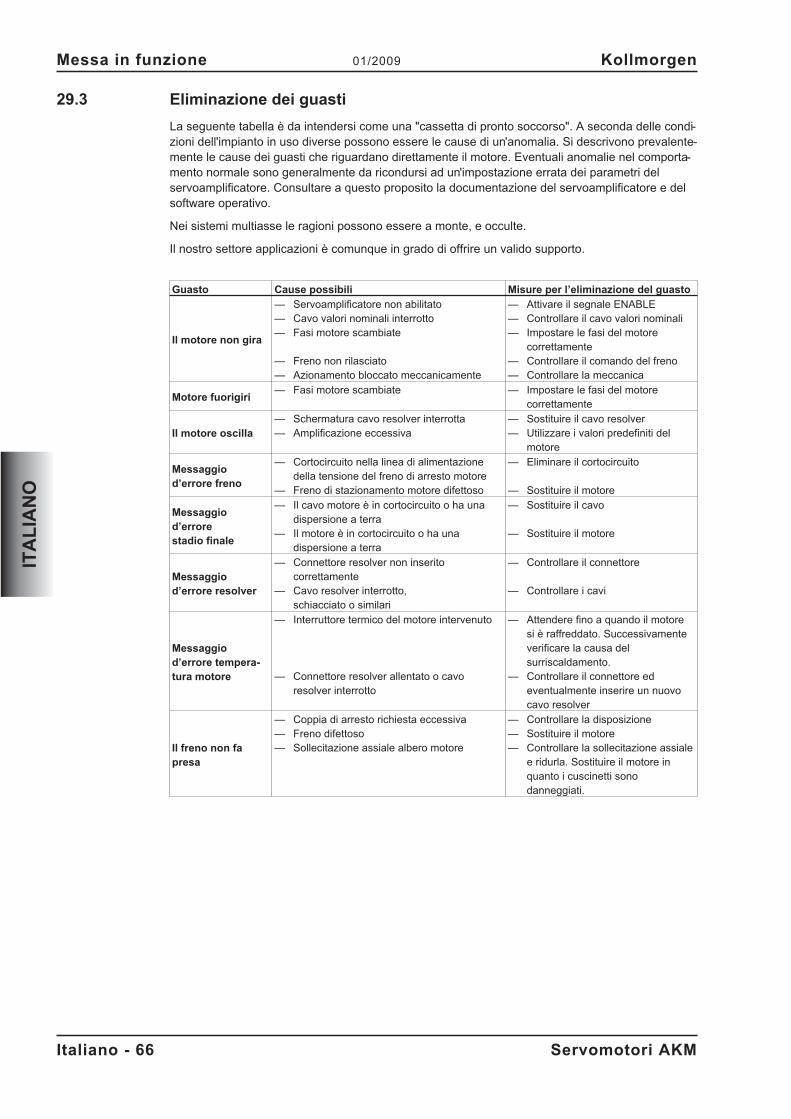
29.3 Eliminazione dei guasti
La seguente tabella è da intendersi come una "cassetta di pronto soccorso". A seconda delle condi-zioni dell'impianto in uso diverse possono essere le cause di un'anomalia. Si descrivono prevalente-mente le cause dei guasti che riguardano direttamente il motore. Eventuali anomalie nel comporta-mento normale sono generalmente da ricondursi ad un'impostazione errata dei parametri delservoamplificatore. Consultare a questo proposito la documentazione del servoamplificatore e delsoftware operativo.
Nei sistemi multiasse le ragioni possono essere a monte, e occulte.
Il nostro settore applicazioni è comunque in grado di offrire un valido supporto.
Guasto Cause possibili Misure per l’eliminazione del guasto
Il motore non gira
— Servoamplificatore non abilitato— Cavo valori nominali interrotto— Fasi motore scambiate
— Freno non rilasciato— Azionamento bloccato meccanicamente
— Attivare il segnale ENABLE— Controllare il cavo valori nominali— Impostare le fasi del motore
correttamente— Controllare il comando del freno— Controllare la meccanica
Motore fuorigiri— Fasi motore scambiate — Impostare le fasi del motore
correttamente
Il motore oscilla— Schermatura cavo resolver interrotta— Amplificazione eccessiva
— Sostituire il cavo resolver— Utilizzare i valori predefiniti del
motore
Messaggiod’errore freno
— Cortocircuito nella linea di alimentazionedella tensione del freno di arresto motore
— Freno di stazionamento motore difettoso
— Eliminare il cortocircuito
— Sostituire il motore
Messaggiod’errorestadio finale
— Il cavo motore è in cortocircuito o ha unadispersione a terra
— Il motore è in cortocircuito o ha unadispersione a terra
— Sostituire il cavo
— Sostituire il motore
Messaggiod’errore resolver
— Connettore resolver non inseritocorrettamente
— Cavo resolver interrotto,schiacciato o similari
— Controllare il connettore
— Controllare i cavi
Messaggiod’errore tempera-tura motore
— Interruttore termico del motore intervenuto
— Connettore resolver allentato o cavoresolver interrotto
— Attendere fino a quando il motoresi è raffreddato. Successivamenteverificare la causa delsurriscaldamento.
— Controllare il connettore edeventualmente inserire un nuovocavo resolver
Il freno non fapresa
— Coppia di arresto richiesta eccessiva— Freno difettoso— Sollecitazione assiale albero motore
— Controllare la disposizione— Sostituire il motore— Controllare la sollecitazione assiale
e ridurla. Sostituire il motore inquanto i cuscinetti sonodanneggiati.
Italiano - 66 Servomotori AKM
Messa in funzione 01/2009 Kollmorgen
ITA
LIA
NO
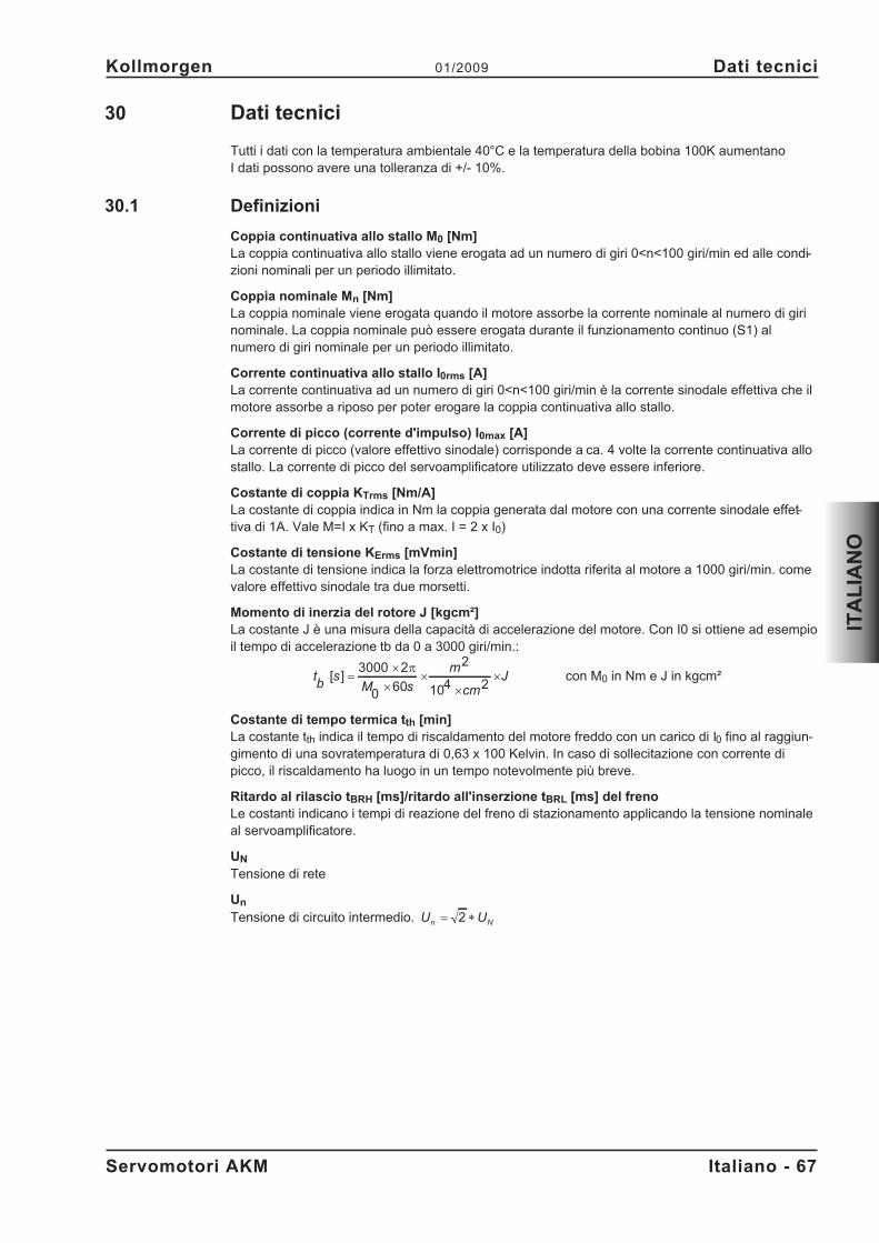
30 Dati tecnici
Tutti i dati con la temperatura ambientale 40°C e la temperatura della bobina 100K aumentanoI dati possono avere una tolleranza di +/- 10%.
30.1 Definizioni
Coppia continuativa allo stallo M0 [Nm]La coppia continuativa allo stallo viene erogata ad un numero di giri 0<n<100 giri/min ed alle condi-zioni nominali per un periodo illimitato.
Coppia nominale Mn [Nm]La coppia nominale viene erogata quando il motore assorbe la corrente nominale al numero di girinominale. La coppia nominale può essere erogata durante il funzionamento continuo (S1) alnumero di giri nominale per un periodo illimitato.
Corrente continuativa allo stallo I0rms [A]La corrente continuativa ad un numero di giri 0<n<100 giri/min è la corrente sinodale effettiva che ilmotore assorbe a riposo per poter erogare la coppia continuativa allo stallo.
Corrente di picco (corrente d'impulso) I0max [A]La corrente di picco (valore effettivo sinodale) corrisponde a ca. 4 volte la corrente continuativa allostallo. La corrente di picco del servoamplificatore utilizzato deve essere inferiore.
Costante di coppia KTrms [Nm/A]La costante di coppia indica in Nm la coppia generata dal motore con una corrente sinodale effet-tiva di 1A. Vale M=I x KT (fino a max. I = 2 x I0)
Costante di tensione KErms [mVmin]La costante di tensione indica la forza elettromotrice indotta riferita al motore a 1000 giri/min. comevalore effettivo sinodale tra due morsetti.
Momento di inerzia del rotore J [kgcm²]La costante J è una misura della capacità di accelerazione del motore. Con I0 si ottiene ad esempioil tempo di accelerazione tb da 0 a 3000 giri/min.:
tb
sM s
m
cm
J[ ] ��
��
�
�3000 2
0 60
2
104 2�
con M0 in Nm e J in kgcm²
Costante di tempo termica tth [min]La costante tth indica il tempo di riscaldamento del motore freddo con un carico di I0 fino al raggiun-gimento di una sovratemperatura di 0,63 x 100 Kelvin. In caso di sollecitazione con corrente dipicco, il riscaldamento ha luogo in un tempo notevolmente più breve.
Ritardo al rilascio tBRH [ms]/ritardo all'inserzione tBRL [ms] del frenoLe costanti indicano i tempi di reazione del freno di stazionamento applicando la tensione nominaleal servoamplificatore.
UN
Tensione di rete
Un
Tensione di circuito intermedio. U Un N
� �2
Servomotori AKM Italiano - 67
Kollmorgen 01/2009 Dati tecnici
ITA
LIA
NO
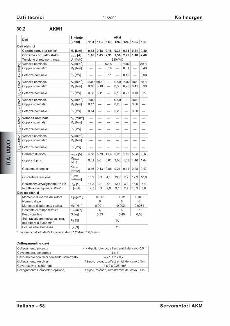
30.2 AKM1
DatiSimbolo[unità]
AKM
11B 11C 11E 12C 12E 13C 13D
Dati elettrici
Coppia cont. allo stallo* M0 [Nm] 0,18 0,18 0,18 0,31 0,31 0,41 0,40
Corrente cont. allo stallo I0rms [A] 1,16 1,45 2,91 1,51 2,72 1,48 2,40
Tensione di rete nom. max. UN [VAC] 230VAC
U=
75
VD
C Velocità nominale nn [min-1] — — 6000 — 3000 — 2000
Coppia nominale* Mn [Nm] — — 0,18 — 0,31 — 0,40
Potenza nominale Pn [kW] — — 0,11 — 0,10 — 0,08
UN
=1
15
V Velocità nominale nn [min-1] 4000 6000 — 4000 8000 3000 7000
Coppia nominale* Mn [Nm] 0,18 0,18 — 0,30 0,28 0,41 0,36
Potenza nominale Pn [kW] 0,08 0,11 — 0,13 0,23 0,13 0,27
UN
=2
30
V Velocità nominale nn [min-1] 8000 — — 8000 — 8000 —
Coppia nominale* Mn [Nm] 0,17 — — 0,28 — 0,36 —
Potenza nominale Pn [kW] 0,14 — — 0,23 — 0,30 —
UN
=4
00
V Velocità nominale nn [min-1] — — — — — — —
Coppia nominale* Mn [Nm] — — — — — — —
Potenza nominale Pn [kW] — — — — — — —
UN
=4
80
V Velocità nominale nn [min-1] — — — — — — —
Coppia nominale* Mn [Nm] — — — — — — —
Potenza nominale Pn [kW] — — — — — — —
Corrente di picco I0max [A] 4,65 5,79 11,6 6,06 10,9 5,93 9,6
Coppia di piccoM0max
[Nm]0,61 0,61 0,61 1,08 1,08 1,46 1,44
Costante di coppiaKTrms
[Nm/A]0,16 0,13 0,06 0,21 0,11 0,28 0,17
Costante di tensioneKErms
[mVmin]10,2 8,3 4,1 13,3 7,2 17,9 10,9
Resistenza avvolgimento Ph-Ph R25 [] 18,2 12,1 3,1 12,4 3,9 13,5 5,4
Induttivà avvolgimento Ph-Ph L [mH] 12,5 8,3 2,0 9,1 2,7 10,3 3,8
Dati meccanici
Momento di inerzia del rotore J [kgcm²] 0,017 0,031 0,045
Numero di poli 6 6 6
Momento di aderenza statica MR [Nm] 0,0011 0,0021 0,0031
Costante di tempo termica tTH [min] 4 6 7
Peso standard G [kg] 0,35 0,49 0,63
Soll. radiale ammessa sull estr.dell'albero a 8000 min-1 FR [N] 30
Soll. assiale ammessa FA [N] 12
* Flangia di calcolo dell'alluminio 254mm * 254mm * 6,35mm
Collegamenti e cavi
Collegamento potenza 4 + 4-poli, rotondo, all'estremità del cavo 0,5m
Cavo motore, schermato 4 x 1
Cavo motore con fili di comando, schermato 4 x 1 + 2 x 0,75
Collegamento resolver 12-poli, rotondo, all'estremità del cavo 0,5m
Cavo resolver, schermato 4 x 2 x 0,25mm²
Collegamento Comcoder (opzione) 17-poli, rotondo, all'estremità del cavo 0,5m
Italiano - 68 Servomotori AKM
Dati tecnici 01/2009 Kollmorgen
ITA
LIA
NO
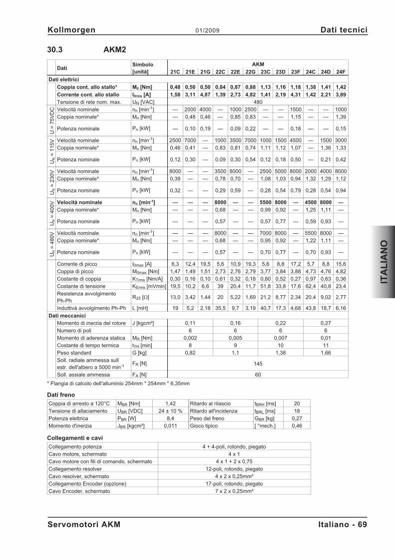
30.3 AKM2
DatiSimbolo[unità]
AKM
21C 21E 21G 22C 22E 22G 23C 23D 23F 24C 24D 24F
Dati elettrici
Coppia cont. allo stallo* M0 [Nm] 0,48 0,50 0,50 0,84 0,87 0,88 1,13 1,16 1,18 1,38 1,41 1,42
Corrente cont. allo stallo I0rms [A] 1,58 3,11 4,87 1,39 2,73 4,82 1,41 2,19 4,31 1,42 2,21 3,89
Tensione di rete nom. max. UN [VAC] 480
U=
75
VD
C Velocità nominale nn [min-1] — 2000 4000 — 1000 2500 — — 1500 — — 1000
Coppia nominale* Mn [Nm] — 0,48 0,46 — 0,85 0,83 — — 1,15 — — 1,39
Potenza nominale Pn [kW] — 0,10 0,19 — 0,09 0,22 — — 0,18 — — 0,15
UN
=1
15
V Velocità nominale nn [min-1] 2500 7000 — 1000 3500 7000 1000 1500 4500 — 1500 3000
Coppia nominale* Mn [Nm] 0,46 0,41 — 0,83 0,81 0,74 1,11 1,12 1,07 — 1,36 1,33
Potenza nominale Pn [kW] 0,12 0,30 — 0,09 0,30 0,54 0,12 0,18 0,50 — 0,21 0,42
UN
=2
30
V Velocità nominale nn [min-1] 8000 — — 3500 8000 — 2500 5000 8000 2000 4000 8000
Coppia nominale* Mn [Nm] 0,39 — — 0,78 0,70 — 1,08 1,03 0,94 1,32 1,29 1,12
Potenza nominale Pn [kW] 0,32 — — 0,29 0,59 — 0,28 0,54 0,79 0,28 0,54 0,94
UN
=4
00
V Velocità nominale nn [min-1] — — — 8000 — — 5500 8000 — 4500 8000 —
Coppia nominale* Mn [Nm] — — — 0,68 — — 0,99 0,92 — 1,25 1,11 —
Potenza nominale Pn [kW] — — — 0,57 — — 0,57 0,77 — 0,59 0,93 —
UN
=4
80
V Velocità nominale nn [min-1] — — — 8000 — — 7000 8000 — 5500 8000 —
Coppia nominale* Mn [Nm] — — — 0,68 — — 0,95 0,92 — 1,22 1,11 —
Potenza nominale Pn [kW] — — — 0,57 — — 0,70 0,77 — 0,70 0,93 —
Corrente di picco I0max [A] 6,3 12,4 19,5 5,6 10,9 19,3 5,6 8,8 17,2 5,7 8,8 15,6
Coppia di picco M0max [Nm] 1,47 1,49 1,51 2,73 2,76 2,79 3,77 3,84 3,88 4,73 4,76 4,82
Costante di coppia KTrms [Nm/A] 0,30 0,16 0,10 0,61 0,32 0,18 0,80 0,52 0,27 0,97 0,63 0,36
Costante di tensione KErms [mVmin] 19,5 10,2 6,6 39 20,4 11,7 51,8 33,8 17,6 62,4 40,8 23,4
Resistenza avvolgimentoPh-Ph
R25 [] 13,0 3,42 1,44 20 5,22 1,69 21,2 8,77 2,34 20,4 9,02 2,77
Induttivà avvolgimento Ph-Ph L [mH] 19 5,2 2,18 35,5 9,7 3,19 40,7 17,3 4,68 43,8 18,7 6,16
Dati meccanici
Momento di inerzia del rotore J [kgcm²] 0,11 0,16 0,22 0,27
Numero di poli 6 6 6 6
Momento di aderenza statica MR [Nm] 0,002 0,005 0,007 0,01
Costante di tempo termica tTH [min] 8 9 10 11
Peso standard G [kg] 0,82 1,1 1,38 1,66
Soll. radiale ammessa sullestr. dell'albero a 5000 min-1 FR [N] 145
Soll. assiale ammessa FA [N] 60
* Flangia di calcolo dell'alluminio 254mm * 254mm * 6,35mm
Dati freno
Coppia di arresto a 120°C MBR [Nm] 1,42 Ritardo al rilascio tBRH [ms] 20
Tensione di allaciamento UBR [VDC] 24 ± 10 % Ritardo all'incidenza tBRL [ms] 18
Potenza elettrica PBR [W] 8,4 Peso del freno GBR [kg] 0,27
Momento d'inerzia JBR [kgcm²] 0,011 Gioco tipico [ °mech.] 0,46
Collegamenti e cavi
Collegamento potenza 4 + 4-poli, rotondo, piegato
Cavo motore, schermato 4 x 1
Cavo motore con fili di comando, schermato 4 x 1 + 2 x 0,75
Collegamento resolver 12-poli, rotondo, piegato
Cavo resolver, schermato 4 x 2 x 0,25mm²
Collegamento Encoder (opzione) 17-poli, rotondo, piegato
Cavo Encoder, schermato 7 x 2 x 0,25mm²
Servomotori AKM Italiano - 69
Kollmorgen 01/2009 Dati tecnici
ITA
LIA
NO
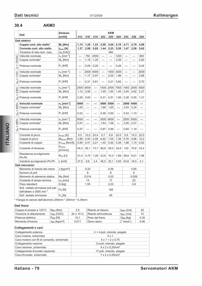
30.4 AKM3
DatiSimbolo[unità]
AKM
31C 31E 31H 32C 32D 32H 33C 33E 33H
Dati elettrici
Coppia cont. allo stallo* M0 [Nm] 1,15 1,20 1,23 2,00 2,04 2,10 2,71 2,79 2,88
Corrente cont. allo stallo I0rms [A] 1,37 2,99 5,85 1,44 2,23 5,50 1,47 2,58 5,62
Tensione di rete nom. max. UN [VAC] 480
U=
75
VD
C Velocità nominale nn [min-1] — 750 2000 — — 1200 — — 800
Coppia nominale* Mn [Nm] — 1,19 1,20 — — 2,06 — — 2,82
Potenza nominale Pn [kW] — 0,09 0,25 — — 0,26 — — 0,24
UN
=1
15
V Velocità nominale nn [min-1] — 2500 6000 — 1000 3000 — — 2500
Coppia nominale* Mn [Nm] — 1,17 0,97 — 2,00 1,96 — — 2,66
Potenza nominale Pn [kW] — 0,31 0,61 — 0,21 0,62 — — 0,70
UN
=2
30
V Velocità nominale nn [min-1] 2500 6000 — 1500 2500 7000 1000 2000 5500
Coppia nominale* Mn [Nm] 1,12 0,95 — 1,95 1,93 1,45 2,64 2,62 2,27
Potenza nominale Pn [kW] 0,29 0,60 — 0,31 0,51 1,06 0,28 0,55 1,31
UN
=4
00
V Velocità nominale nn [min-1] 5000 — — 3000 5500 — 2000 4500 —
Coppia nominale* Mn [Nm] 1,00 — — 1,86 1,65 — 2,54 2,34 —
Potenza nominale Pn [kW] 0,52 — — 0,58 0,95 — 0,53 1,10 —
UN
=4
80
V Velocità nominale nn [min-1] 6000 — — 3500 6000 — 2500 5000 —
Coppia nominale* Mn [Nm] 0,91 — — 1,83 1,58 — 2,50 2,27 —
Potenza nominale Pn [kW] 0,57 — — 0,67 0,99 — 0,65 1,19 —
Corrente di picco I0max [A] 5,5 12,0 23,4 5,7 8,9 22,0 5,9 10,3 22,5
Coppia di picco M0max [Nm] 3,88 4,00 4,06 6,92 7,05 7,26 9,76 9,96 10,2
Costante di coppia KTrms [Nm/A] 0,85 0,41 0,21 1,40 0,92 0,39 1,86 1,10 0,52
Costante di tensioneKErms
[mVmin]54,5 26,1 13,7 89,8 59,0 24,8 120 70,6 33,4
Resistenza avvolgimentoPh-Ph
R25 [] 21,4 4,74 1,29 23,8 10,3 1,69 26,6 9,01 1,96
Induttivà avvolgimento Ph-Ph L [mH] 37,5 8,6 2,4 46,5 20,1 3,55 53,6 18,5 4,1
Dati meccanici
Momento di inerzia del rotore J [kgcm²] 0,33 0,59 0,85
Numero di poli 8 8 8
Momento di aderenza statica MR [Nm] 0,014 0,02 0,026
Costante di tempo termica tTH [min] 14 17 20
Peso standard G [kg] 1,55 2,23 2,9
Soll. radiale ammessa sull estr.dell'albero a 3000 min-1 FR [N] 195
Soll. assiale ammessa FA [N] 65
* Flangia di calcolo dell'alluminio 254mm * 254mm * 6,35mm
Dati freno
Coppia di arresto a 120°C MBR [Nm] 2,5 Ritardo al rilascio tBRH [ms] 25
Tensione di allaciamento UBR [VDC] 24 ± 10 % Ritardo all'incidenza tBRL [ms] 10
Potenza elettrica PBR [W] 10,1 Peso del freno GBR [kg] 0,35
Momento d'inerzia JBR [kgcm²] 0,011 Gioco tipico [ °mech.] 0,46
Collegamenti e cavi
Collegamento potenza 4 + 4-poli, rotondo, piegato
Cavo motore, schermato 4 x 1
Cavo motore con fili di comando, schermato 4 x 1 + 2 x 0,75
Collegamento resolver 12-poli, rotondo, piegato
Cavo resolver, schermato 4 x 2 x 0,25mm²
Collegamento Encoder (opzione) 17-poli, rotondo, piegato
Cavo Encoder, schermato 7 x 2 x 0,25mm²
Italiano - 70 Servomotori AKM
Dati tecnici 01/2009 Kollmorgen
ITA
LIA
NO
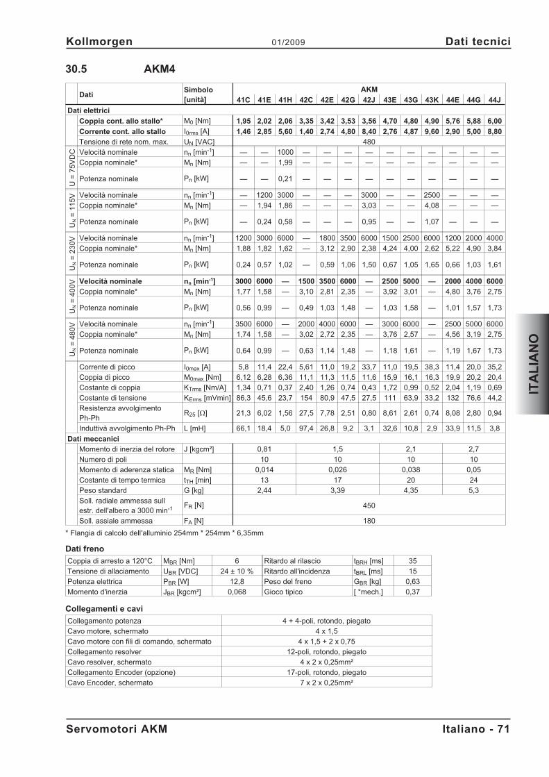
30.5 AKM4
DatiSimbolo[unità]
AKM
41C 41E 41H 42C 42E 42G 42J 43E 43G 43K 44E 44G 44J
Dati elettrici
Coppia cont. allo stallo* M0 [Nm] 1,95 2,02 2,06 3,35 3,42 3,53 3,56 4,70 4,80 4,90 5,76 5,88 6,00
Corrente cont. allo stallo I0rms [A] 1,46 2,85 5,60 1,40 2,74 4,80 8,40 2,76 4,87 9,60 2,90 5,00 8,80
Tensione di rete nom. max. UN [VAC] 480
U=
75
VD
C Velocità nominale nn [min-1] — — 1000 — — — — — — — — — —
Coppia nominale* Mn [Nm] — — 1,99 — — — — — — — — — —
Potenza nominale Pn [kW] — — 0,21 — — — — — — — — — —
UN
=1
15
V Velocità nominale nn [min-1] — 1200 3000 — — — 3000 — — 2500 — — —
Coppia nominale* Mn [Nm] — 1,94 1,86 — — — 3,03 — — 4,08 — — —
Potenza nominale Pn [kW] — 0,24 0,58 — — — 0,95 — — 1,07 — — —
UN
=2
30
V Velocità nominale nn [min-1] 1200 3000 6000 — 1800 3500 6000 1500 2500 6000 1200 2000 4000
Coppia nominale* Mn [Nm] 1,88 1,82 1,62 — 3,12 2,90 2,38 4,24 4,00 2,62 5,22 4,90 3,84
Potenza nominale Pn [kW] 0,24 0,57 1,02 — 0,59 1,06 1,50 0,67 1,05 1,65 0,66 1,03 1,61
UN
=4
00
V Velocità nominale nn [min-1] 3000 6000 — 1500 3500 6000 — 2500 5000 — 2000 4000 6000
Coppia nominale* Mn [Nm] 1,77 1,58 — 3,10 2,81 2,35 — 3,92 3,01 — 4,80 3,76 2,75
Potenza nominale Pn [kW] 0,56 0,99 — 0,49 1,03 1,48 — 1,03 1,58 — 1,01 1,57 1,73
UN
=4
80
V Velocità nominale nn [min-1] 3500 6000 — 2000 4000 6000 — 3000 6000 — 2500 5000 6000
Coppia nominale* Mn [Nm] 1,74 1,58 — 3,02 2,72 2,35 — 3,76 2,57 — 4,56 3,19 2,75
Potenza nominale Pn [kW] 0,64 0,99 — 0,63 1,14 1,48 — 1,18 1,61 — 1,19 1,67 1,73
Corrente di picco I0max [A] 5,8 11,4 22,4 5,61 11,0 19,2 33,7 11,0 19,5 38,3 11,4 20,0 35,2
Coppia di picco M0max [Nm] 6,12 6,28 6,36 11,1 11,3 11,5 11,6 15,9 16,1 16,3 19,9 20,2 20,4
Costante di coppia KTrms [Nm/A] 1,34 0,71 0,37 2,40 1,26 0,74 0,43 1,72 0,99 0,52 2,04 1,19 0,69
Costante di tensione KErms [mVmin] 86,3 45,6 23,7 154 80,9 47,5 27,5 111 63,9 33,2 132 76,6 44,2
Resistenza avvolgimentoPh-Ph
R25 [] 21,3 6,02 1,56 27,5 7,78 2,51 0,80 8,61 2,61 0,74 8,08 2,80 0,94
Induttivà avvolgimento Ph-Ph L [mH] 66,1 18,4 5,0 97,4 26,8 9,2 3,1 32,6 10,8 2,9 33,9 11,5 3,8
Dati meccanici
Momento di inerzia del rotore J [kgcm²] 0,81 1,5 2,1 2,7
Numero di poli 10 10 10 10
Momento di aderenza statica MR [Nm] 0,014 0,026 0,038 0,05
Costante di tempo termica tTH [min] 13 17 20 24
Peso standard G [kg] 2,44 3,39 4,35 5,3
Soll. radiale ammessa sullestr. dell'albero a 3000 min-1 FR [N] 450
Soll. assiale ammessa FA [N] 180
* Flangia di calcolo dell'alluminio 254mm * 254mm * 6,35mm
Dati freno
Coppia di arresto a 120°C MBR [Nm] 6 Ritardo al rilascio tBRH [ms] 35
Tensione di allaciamento UBR [VDC] 24 ± 10 % Ritardo all'incidenza tBRL [ms] 15
Potenza elettrica PBR [W] 12,8 Peso del freno GBR [kg] 0,63
Momento d'inerzia JBR [kgcm²] 0,068 Gioco tipico [ °mech.] 0,37
Collegamenti e cavi
Collegamento potenza 4 + 4-poli, rotondo, piegato
Cavo motore, schermato 4 x 1,5
Cavo motore con fili di comando, schermato 4 x 1,5 + 2 x 0,75
Collegamento resolver 12-poli, rotondo, piegato
Cavo resolver, schermato 4 x 2 x 0,25mm²
Collegamento Encoder (opzione) 17-poli, rotondo, piegato
Cavo Encoder, schermato 7 x 2 x 0,25mm²
Servomotori AKM Italiano - 71
Kollmorgen 01/2009 Dati tecnici
ITA
LIA
NO
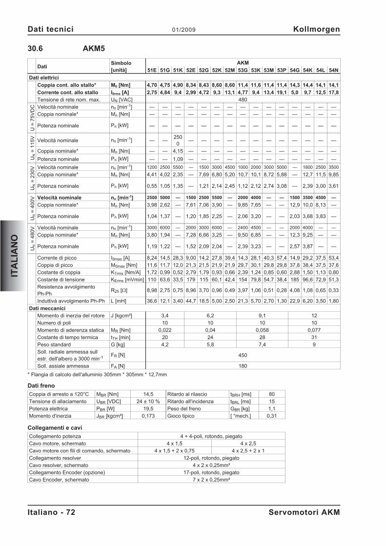
30.6 AKM5
DatiSimbolo[unità]
AKM
51E 51G 51K 52E 52G 52K 52M 53G 53K 53M 53P 54G 54K 54L 54N
Dati elettrici
Coppia cont. allo stallo* M0 [Nm] 4,70 4,75 4,90 8,34 8,43 8,60 8,60 11,4 11,6 11,4 11,4 14,3 14,4 14,1 14,1
Corrente cont. allo stallo I0rms [A] 2,75 4,84 9,4 2,99 4,72 9,3 13,1 4,77 9,4 13,4 19,1 5,0 9,7 12,5 17,8
Tensione di rete nom. max. UN [VAC] 480
U=
75
VD
C Velocità nominale nn [min-1] — — — — — — — — — — — — — — —
Coppia nominale* Mn [Nm] — — — — — — — — — — — — — — —
Potenza nominale Pn [kW] — — — — — — — — — — — — — — —
UN
=1
15
V Velocità nominale nn [min-1] — —250
0— — — — — — — — — — — —
Coppia nominale* Mn [Nm] — — 4,15 — — — — — — — — — — — —
Potenza nominale Pn [kW] — — 1,09 — — — — — — — — — — — —
UN
=2
30
V Velocità nominale nn [min-1] 1200 2500 5500 — 1500 3000 4500 1000 2000 3000 5000 — 1800 2500 3500
Coppia nominale* Mn [Nm] 4,41 4,02 2,35 — 7,69 6,80 5,20 10,7 10,1 8,72 5,88 — 12,7 11,5 9,85
Potenza nominale Pn [kW] 0,55 1,05 1,35 — 1,21 2,14 2,45 1,12 2,12 2,74 3,08 — 2,39 3,00 3,61
UN
=4
00
V Velocità nominale nn [min-1] 2500 5000 — 1500 2500 5500 — 2000 4000 — — 1500 3500 4500 —
Coppia nominale* Mn [Nm] 3,98 2,62 — 7,61 7,06 3,90 — 9,85 7,65 — — 12,9 10,0 8,13 —
Potenza nominale Pn [kW] 1,04 1,37 — 1,20 1,85 2,25 — 2,06 3,20 — — 2,03 3,68 3,83 —
UN
=4
80
V Velocità nominale nn [min-1] 3000 6000 — 2000 3000 6000 — 2400 4500 — — 2000 4000 — —
Coppia nominale* Mn [Nm] 3,80 1,94 — 7,28 6,66 3,25 — 9,50 6,85 — — 12,3 9,25 — —
Potenza nominale Pn [kW] 1,19 1,22 — 1,52 2,09 2,04 — 2,39 3,23 — — 2,57 3,87 — —
Corrente di picco I0max [A] 8,24 14,5 28,3 9,00 14,2 27,8 39,4 14,3 28,1 40,3 57,4 14,9 29,2 37,5 53,4
Coppia di picco M0max [Nm] 11,6 11,7 12,0 21,3 21,5 21,9 21,9 29,7 30,1 29,8 29,8 37,8 38,4 37,5 37,6
Costante di coppia KTrms [Nm/A] 1,72 0,99 0,52 2,79 1,79 0,93 0,66 2,39 1,24 0,85 0,60 2,88 1,50 1,13 0,80
Costante di tensione KErms [mVmin] 110 63,6 33,5 179 115 60,1 42,4 154 79,8 54,7 38,4 185 96,6 72,9 51,3
Resistenza avvolgimentoPh-Ph
R25 [] 8,98 2,75 0,75 8,96 3,70 0,96 0,49 3,97 1,06 0,51 0,28 4,08 1,08 0,65 0,33
Induttivà avvolgimento Ph-Ph L [mH] 36,6 12,1 3,40 44,7 18,5 5,00 2,50 21,3 5,70 2,70 1,30 22,9 6,20 3,50 1,80
Dati meccanici
Momento di inerzia del rotore J [kgcm²] 3,4 6,2 9,1 12
Numero di poli 10 10 10 10
Momento di aderenza statica MR [Nm] 0,022 0,04 0,058 0,077
Costante di tempo termica tTH [min] 20 24 28 31
Peso standard G [kg] 4,2 5,8 7,4 9
Soll. radiale ammessa sullestr. dell'albero a 3000 min-1 FR [N] 450
Soll. assiale ammessa FA [N] 180
* Flangia di calcolo dell'alluminio 305mm * 305mm * 12,7mm
Dati freno
Coppia di arresto a 120°C MBR [Nm] 14,5 Ritardo al rilascio tBRH [ms] 80
Tensione di allaciamento UBR [VDC] 24 ± 10 % Ritardo all'incidenza tBRL [ms] 15
Potenza elettrica PBR [W] 19,5 Peso del freno GBR [kg] 1,1
Momento d'inerzia JBR [kgcm²] 0,173 Gioco tipico [ °mech.] 0,31
Collegamenti e cavi
Collegamento potenza 4 + 4-poli, rotondo, piegato
Cavo motore, schermato 4 x 1,5 4 x 2,5
Cavo motore con fili di comando, schermato 4 x 1,5 + 2 x 0,75 4 x 2,5 + 2 x 1
Collegamento resolver 12-poli, rotondo, piegato
Cavo resolver, schermato 4 x 2 x 0,25mm²
Collegamento Encoder (opzione) 17-poli, rotondo, piegato
Cavo Encoder, schermato 7 x 2 x 0,25mm²
Italiano - 72 Servomotori AKM
Dati tecnici 01/2009 Kollmorgen
ITA
LIA
NO
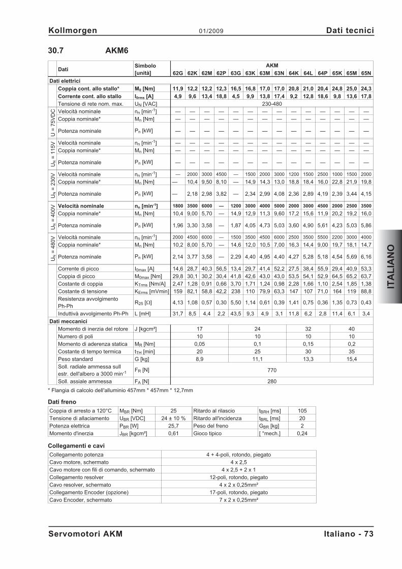
30.7 AKM6
DatiSimbolo[unità]
AKM
62G 62K 62M 62P 63G 63K 63M 63N 64K 64L 64P 65K 65M 65N
Dati elettrici
Coppia cont. allo stallo* M0 [Nm] 11,9 12,2 12,2 12,3 16,5 16,8 17,0 17,0 20,8 21,0 20,4 24,8 25,0 24,3
Corrente cont. allo stallo I0rms [A] 4,9 9,6 13,4 18,8 4,5 9,9 13,8 17,4 9,2 12,8 18,6 9,8 13,6 17,8
Tensione di rete nom. max. UN [VAC] 230-480
U=
75
VD
C Velocità nominale nn [min-1] — — — — — — — — — — — — — —
Coppia nominale* Mn [Nm] — — — — — — — — — — — — — —
Potenza nominale Pn [kW] — — — — — — — — — — — — — —
UN
=1
15
V Velocità nominale nn [min-1] — — — — — — — — — — — — — —
Coppia nominale* Mn [Nm] — — — — — — — — — — — — — —
Potenza nominale Pn [kW] — — — — — — — — — — — — — —
UN
=2
30
V Velocità nominale nn [min-1] — 2000 3000 4500 — 1500 2000 3000 1200 1500 2500 1000 1500 2000
Coppia nominale* Mn [Nm] — 10,4 9,50 8,10 — 14,9 14,3 13,0 18,8 18,4 16,0 22,8 21,9 19,8
Potenza nominale Pn [kW] — 2,18 2,98 3,82 — 2,34 2,99 4,08 2,36 2,89 4,19 2,39 3,44 4,15
UN
=4
00
V Velocità nominale nn [min-1] 1800 3500 6000 — 1200 3000 4000 5000 2000 3000 4500 2000 2500 3500
Coppia nominale* Mn [Nm] 10,4 9,00 5,70 — 14,9 12,9 11,3 9,60 17,2 15,6 11,9 20,2 19,2 16,0
Potenza nominale Pn [kW] 1,96 3,30 3,58 — 1,87 4,05 4,73 5,03 3,60 4,90 5,61 4,23 5,03 5,86
UN
=4
80
V Velocità nominale nn [min-1] 2000 4500 6000 — 1500 3500 4500 6000 2500 3500 5500 2200 3000 4000
Coppia nominale* Mn [Nm] 10,2 8,00 5,70 — 14,6 12,0 10,5 7,00 16,3 14,4 9,00 19,7 18,1 14,7
Potenza nominale Pn [kW] 2,14 3,77 3,58 — 2,29 4,40 4,95 4,40 4,27 5,28 5,18 4,54 5,69 6,16
Corrente di picco I0max [A] 14,6 28,7 40,3 56,5 13,4 29,7 41,4 52,2 27,5 38,4 55,9 29,4 40,9 53,3
Coppia di picco M0max [Nm] 29,8 30,1 30,2 30,4 41,8 42,6 43,0 43,0 53,5 54,1 52,9 64,5 65,2 63,7
Costante di coppia KTrms [Nm/A] 2,47 1,28 0,91 0,66 3,70 1,71 1,24 0,98 2,28 1,66 1,10 2,54 1,85 1,38
Costante di tensione KErms [mVmin] 159 82,1 58,8 42,2 238 110 79,9 63,3 147 107 71,0 164 119 88,8
Resistenza avvolgimentoPh-Ph
R25 [] 4,13 1,08 0,57 0,30 5,50 1,14 0,61 0,39 1,41 0,75 0,36 1,35 0,73 0,43
Induttivà avvolgimento Ph-Ph L [mH] 31,7 8,5 4,4 2,2 43,5 9,3 4,9 3,1 11,8 6,2 2,8 11,4 6,1 3,4
Dati meccanici
Momento di inerzia del rotore J [kgcm²] 17 24 32 40
Numero di poli 10 10 10 10
Momento di aderenza statica MR [Nm] 0,05 0,1 0,15 0,2
Costante di tempo termica tTH [min] 20 25 30 35
Peso standard G [kg] 8,9 11,1 13,3 15,4
Soll. radiale ammessa sullestr. dell'albero a 3000 min-1 FR [N] 770
Soll. assiale ammessa FA [N] 280
* Flangia di calcolo dell'alluminio 457mm * 457mm * 12,7mm
Dati freno
Coppia di arresto a 120°C MBR [Nm] 25 Ritardo al rilascio tBRH [ms] 105
Tensione di allaciamento UBR [VDC] 24 ± 10 % Ritardo all'incidenza tBRL [ms] 20
Potenza elettrica PBR [W] 25,7 Peso del freno GBR [kg] 2
Momento d'inerzia JBR [kgcm²] 0,61 Gioco tipico [ °mech.] 0,24
Collegamenti e cavi
Collegamento potenza 4 + 4-poli, rotondo, piegato
Cavo motore, schermato 4 x 2,5
Cavo motore con fili di comando, schermato 4 x 2,5 + 2 x 1
Collegamento resolver 12-poli, rotondo, piegato
Cavo resolver, schermato 4 x 2 x 0,25mm²
Collegamento Encoder (opzione) 17-poli, rotondo, piegato
Cavo Encoder, schermato 7 x 2 x 0,25mm²
Servomotori AKM Italiano - 73
Kollmorgen 01/2009 Dati tecnici
ITA
LIA
NO
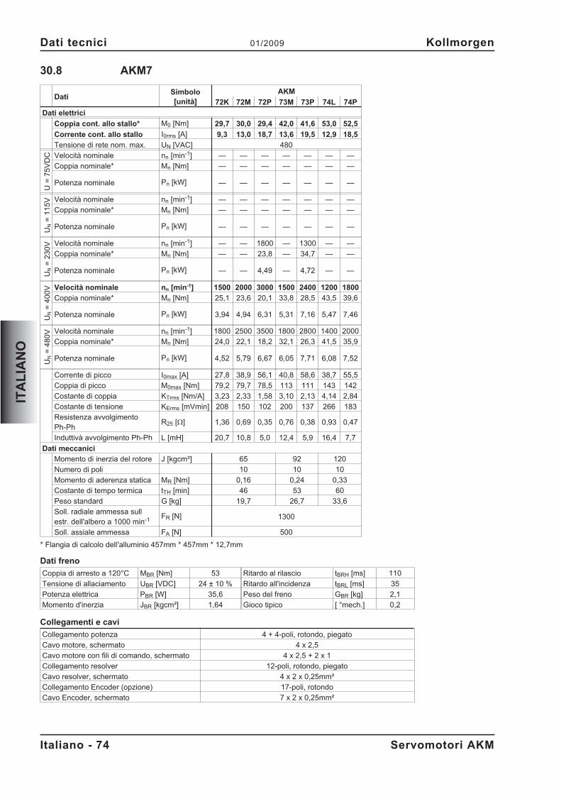
30.8 AKM7
DatiSimbolo[unità]
AKM
72K 72M 72P 73M 73P 74L 74P
Dati elettrici
Coppia cont. allo stallo* M0 [Nm] 29,7 30,0 29,4 42,0 41,6 53,0 52,5
Corrente cont. allo stallo I0rms [A] 9,3 13,0 18,7 13,6 19,5 12,9 18,5
Tensione di rete nom. max. UN [VAC] 480
U=
75
VD
C Velocità nominale nn [min-1] — — — — — — —
Coppia nominale* Mn [Nm] — — — — — — —
Potenza nominale Pn [kW] — — — — — — —
UN
=1
15
V Velocità nominale nn [min-1] — — — — — — —
Coppia nominale* Mn [Nm] — — — — — — —
Potenza nominale Pn [kW] — — — — — — —
UN
=2
30
V Velocità nominale nn [min-1] — — 1800 — 1300 — —
Coppia nominale* Mn [Nm] — — 23,8 — 34,7 — —
Potenza nominale Pn [kW] — — 4,49 — 4,72 — —
UN
=4
00
V Velocità nominale nn [min-1] 1500 2000 3000 1500 2400 1200 1800
Coppia nominale* Mn [Nm] 25,1 23,6 20,1 33,8 28,5 43,5 39,6
Potenza nominale Pn [kW] 3,94 4,94 6,31 5,31 7,16 5,47 7,46
UN
=4
80
V Velocità nominale nn [min-1] 1800 2500 3500 1800 2800 1400 2000
Coppia nominale* Mn [Nm] 24,0 22,1 18,2 32,1 26,3 41,5 35,9
Potenza nominale Pn [kW] 4,52 5,79 6,67 6,05 7,71 6,08 7,52
Corrente di picco I0max [A] 27,8 38,9 56,1 40,8 58,6 38,7 55,5
Coppia di picco M0max [Nm] 79,2 79,7 78,5 113 111 143 142
Costante di coppia KTrms [Nm/A] 3,23 2,33 1,58 3,10 2,13 4,14 2,84
Costante di tensione KErms [mVmin] 208 150 102 200 137 266 183
Resistenza avvolgimentoPh-Ph
R25 [] 1,36 0,69 0,35 0,76 0,38 0,93 0,47
Induttivà avvolgimento Ph-Ph L [mH] 20,7 10,8 5,0 12,4 5,9 16,4 7,7
Dati meccanici
Momento di inerzia del rotore J [kgcm²] 65 92 120
Numero di poli 10 10 10
Momento di aderenza statica MR [Nm] 0,16 0,24 0,33
Costante di tempo termica tTH [min] 46 53 60
Peso standard G [kg] 19,7 26,7 33,6
Soll. radiale ammessa sullestr. dell'albero a 1000 min-1 FR [N] 1300
Soll. assiale ammessa FA [N] 500
* Flangia di calcolo dell'alluminio 457mm * 457mm * 12,7mm
Dati freno
Coppia di arresto a 120°C MBR [Nm] 53 Ritardo al rilascio tBRH [ms] 110
Tensione di allaciamento UBR [VDC] 24 ± 10 % Ritardo all'incidenza tBRL [ms] 35
Potenza elettrica PBR [W] 35,6 Peso del freno GBR [kg] 2,1
Momento d'inerzia JBR [kgcm²] 1,64 Gioco tipico [ °mech.] 0,2
Collegamenti e cavi
Collegamento potenza 4 + 4-poli, rotondo, piegato
Cavo motore, schermato 4 x 2,5
Cavo motore con fili di comando, schermato 4 x 2,5 + 2 x 1
Collegamento resolver 12-poli, rotondo, piegato
Cavo resolver, schermato 4 x 2 x 0,25mm²
Collegamento Encoder (opzione) 17-poli, rotondo
Cavo Encoder, schermato 7 x 2 x 0,25mm²
Italiano - 74 Servomotori AKM
Dati tecnici 01/2009 Kollmorgen
ITA
LIA
NO
31 Generalidades
31.1 Sobre este manual
El presente manual describe los servomotores síncronos de la Serie AKM (modelo estándar).
Los motores son utilizados en el sistema de accionamiento junto con los servoamplificadores. Poreste motivo, tenga presente la totalidad de la documentación del sistema, compuesta por:
— Instrucciones de instalación y de puesta en funcionamiento del servoamplificador— Instrucciones de instalación y de puesta en funcionamiento de una tarjeta de ampliación— eventualmente existente— Manual del usuario de software de operadores del servoamplificador— Manual de accesorios— Descripción técnica de la serie de motores AKM
31.2 Destinatarios
Este manual está dirigido a personal especializado y establece los siguientes requisitos:Transporte: sólo a cargo de personal con conocimientos de manejo de elementos de
montaje con riesgo electrostáticoInstalación mecánica: sólo a cargo de personal especializado con formación en ingeniería
mecánicaInstalación eléctrica: sólo a cargo de personal especializado con formación en electrotecniaPuesta en funcionamiento: sólo a cargo de personal especializado con amplios
conocimientos sobre electrotecnia y la técnica de accionamientosEl personal especializado deberá conocer y observar las siguientes normas y directrices:
IEC 60364 y IEC 60664Normativa nacional de prevención de accidentes
Durante el funcionamiento de los motores existe peligro de muerte, de riesgos graves parala salud o de daños materiales. Por este motivo, el operador debe asegurarse de que secumplan las instrucciones de seguridad incluidas en este manual. El operador debe cercio-rarse de que todas las personas que vayan a realizar trabajos en el motor hayan leído ycomprendido el manual del producto.
31.3 Símbolos utilizados
Peligro para las personas porelectricidad y sus efectos
Precauciones generalesInstrucciones generalesRiesgos para la maquinaria
� Véase capítulo (Referencia cruzada) � Destacar
31.4 Abreviaturas utilizadas
Véase capítulo 40.1 "Definiciones".
Servomotores AKM Español - 75
Kollmorgen 01/2009 Generalidades
ES
PA
ÑO
L
32 Seguridad
32.1 Instrucciones de seguridad
� Las operaciones de transporte, instalación, puesta en funcionamiento y mantenimien-to sólo podrán ser realizadas por personal cualificado. Por personal cualificado seentiende las personas que están familiarizadas con el transporte, la instalación, elmontaje, la puesta en funcionamiento y el manejo del producto y que disponen de lascorrespondientes calificaciones profesionales. El personal especializado deberá co-nocer y observar las siguientes normas y directrices:
IEC 60364 y IEC 60664Normativa nacional de prevención de accidentes
� Antes del montaje y de la puesta en funcionamiento, lea detenidamente la presentedocumentación. La incorrecta manipulación del motor puede producir daños perso-nales y materiales. La observación de los datos técnicos y las indicaciones de conex-ión (placa de identificación y documentación) son de obligado cumplimiento.
� El fabricante de la máquina elaborarár un análisis de riesgo de la máquina y adoptarálas medidas adecuadas para que movimientos imprevistos no puedan causar dañospersonales ni materiales.
� Asegúrese de la adecuada puesta a tierra del bloque del motor con la barra colectoradel armario de distribución como potencial de referencia. Careciendo de una toma detierra de baja resistencia no se puede garantizar la seguridad personal.
� No extraiga ningún enchufe con el equipo en marcha. Existe peligro de muerte, deriesgos graves para la salud y de daños materiales.
� Las conexiones pueden llevar tensión, incluso con el motor parado. No suelte nuncalas conexiones eléctricas estando bajo tensión. En circunstancias desfavorables sepueden producir chispazos que dañen a las personas y a los contactos.
� Al desconectar el servoamplificador de la corriente de alimentación, espere por lomenos cinco minutos antes de soltar piezas conductoras de corriente (por ejemplo,contactos, pernos, etc.). Los condensadores en el servoamplificador conducen ten-siones peligrosas hasta unos cinco minutos después de cortar la alimentación decorriente. Para mayor seguridad, mida la corriente en el circuito intermedio y espere aque la corriente se sitúe por debajo de 40V.
� Durante el funcionamiento, los motores pueden tener superficies calientes según laclase de protección. La temperatura de las superficies puede alcanzar 100°C. Mida latemperatura y, antes de tocar el motor, espere hasta que se haya enfriado a 40°C.
� Si el motor gira libremente, quite/fije el muelle de ajuste que pueda existir, para evitarque salga despedido con el consiguiente peligro de accidente.
Español - 76 Servomotores AKM
Seguridad 01/2009 Kollmorgen
ES
PA
ÑO
L
32.2 Utilización conforme
� Los servomotores sincrónicos de la Serie AKM están diseñados especialmente para el ac-cionamiento de equipos de manipulación, maquinaria textil, máquinas-herramientas, maqui-naria de embalaje y similares con elevados requerimientos dinámicos.
� Están solamente autorizados a operar en motores cumpliendo las condiciones del entornodefinidas en la presente documentación.
� Los motores de la Serie AKM está exclusivamente destinados a ser activados medianteservoamplificadores digitales regulados por velocidad y/o por par motor.
� Los motores se montan como componentes de instalaciones eléctricas o maquinaria y sola-mente pueden ser puestos en servicio como componentes integrados.
� El contacto de termoprotección incorporado en el arrollamiento del motor será evaluado ycomprobado.
� Garantizamos la conformidad del servosistema con los términos de la EC Declaration ofConformity de la página 78, solamente cuando se utilicen los componentes entregados pornosotros (servoamplificador, motor, cables, etc.).
32.3 Uso indebido
� Está prohibido utilizar los motores en los siguientes entornos:- Zonas con riesgo de explosión y entornos con polvos, vapores, aceites, lejías y ácidos
corrosivos o conductores de electricidad- Funcionamiento directo en la red
� Está prohibido utilizar el motor si la máquina en la que está instalado:- no cumple las disposiciones de la directiva comunitaria sobre máquinas;- no cumple las disposiciones de la directiva sobre compatibilidad electromagnética;- no cumple las disposiciones de la directiva sobre equipos de baja tensión.
Servomotores AKM Español - 77
Kollmorgen 01/2009 Seguridad
ES
PA
ÑO
L
33 Normas válidas
33.1 EC Declaration of Conformity
We, the company
Danaher Motion GmbHWacholderstrasse 40-4240489 Düsseldorf
hereby in sole responsibility declare the conformity of the product series
Motor series AKM(Types AKM1, AKM2, AKM3, AKM4, AKM5, AKM6, AKM7)
with the following standards:
- EC Directive 2004/108/ECElectromagnetic compatibilityUsed standard EN61800-3:07/2005
- EC Directive 2006/95/ECElectrical devices for use in special voltage limitsUsed standards
EN60034-1:1998+A1+A2+A3EN60034-5:2001EN60529:1991+A1EN61800-5-1:04/2008
Year of EC-Declaration 2003
Issued by: Product Manager Motors Europe
Jörg Peters
Düsseldorf, 06.01.2009
Legally valid signature
This Declaration does not contain any assurance of properties in the meaning of product liability.The notes on safety and protection in the operating instructions must always be observed.The above-mentioned company has the following technical documentation for examination:- Proper operating instructions- Diagrams (for EU authority only)- Test certificates (for EU authority only)- Other technical documentation (for EU authority only)
Español - 78 Servomotores AKM
Normas válidas 01/2009 Kollmorgen
ES
PA
ÑO
L
34 Manipulación
34.1 Transporte
� Temperatura -25...+70° C, oscilación máx. 20K / horaHumedad del aire humedad relativa máx. 5%... 95% sin condensar
� Sólo a cargo de personal especializado en el envase original reciclable del fabricante
� Evite impactos fuertes, particularmente sobre el extremo del eje
� En caso de que el embalaje esté dañado, compruebe que el aparato no tienedaños visibles. Informe de ello al transportista y, en caso necesario, al fabricante.
34.2 Embalaje
� Caja de cartón amortiguador de la espuma de Instapak®.
� Usted puede volver la porción plástica al surtidor (véase la “Eliminación”).
Modelo Caja de cartón Altura máx. de estiba Modelo Caja de cartón Altura máx. de estiba
AKM1 X 10 AKM5 X 5
AKM2 X 10 AKM6 X 1
AKM3 X 6 AKM7 X 1
AKM4 X 6
34.3 Almacenamiento
� Temp. de almacenamiento -25...+55°C, oscilación máx. 20K/hora
� Humedad del aire humedad rel. máx. 5% ... 95% sin condensar
� Sólo en el embalaje original reciclable del fabricante
� Altura máx. de apilamiento véase en la tabla de embalaje
� Tiempo de almacenamiento sin limitación
34.4 Advertenzia / Limpieza
� Advertenzia / limpieza sólo por personal profesional
� Después de 20.000 horas de servicio en condiciones nominales, se deberían cambiar loscojinetes.
� Compruebe el motor cada 2500 horas de servicio, o bien, una vez al año para ruidos en loscojinetes. Si escucha ruidos en los cojinetes, detenga inmediatamente el motor y cambie loscojinetes
� La apertura de los motores trae consigo la pérdida de la garantía
� Límpiese con isopropanol o producto similar no sumergir ni pulverizar
34.5 Reparación
Sólo el fabricante debe ejecutar reparaciones en el motor; la apertura de los aparatos invalida lagarantía. Ponga el aparato fuera de servicio y envíelo al fabricante:
Danaher Motion GmbHWacholderstr. 40-42D-40489 Düsseldor
34.6 Eliminación
De conformidad con la directiva 2002/96/CE (RAEE), nos encargamos de eliminar de manera ade-cuada los aparatos y accesorios viejos si el remitente se hace cargo de los gastos de transporte.Envíe los aparatos a
Danaher Motion GmbHWacholderstr. 40-42D-40489 Düsseldorf
Servomotores AKM Español - 79
Kollmorgen 01/2009 Manipulación
ES
PA
ÑO
L
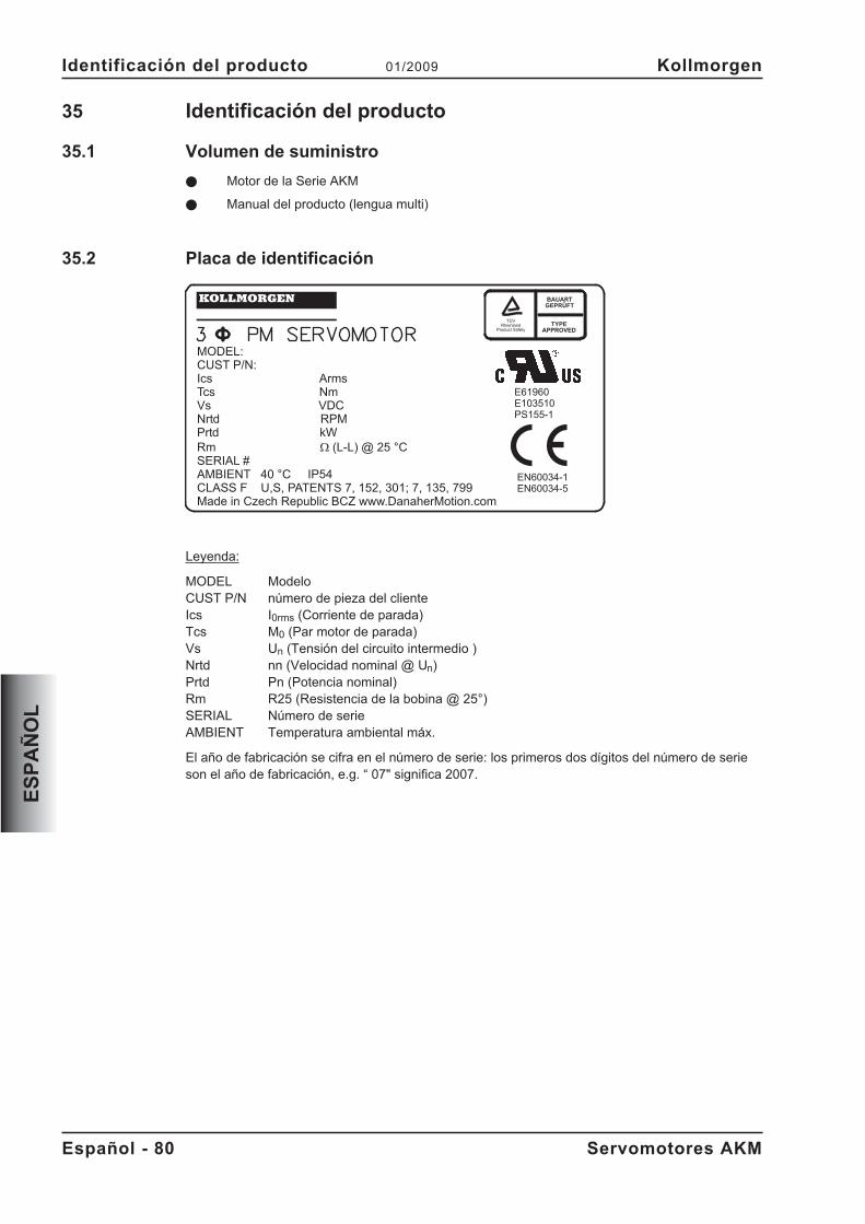
35 Identificación del producto
35.1 Volumen de suministro
� Motor de la Serie AKM
� Manual del producto (lengua multi)
35.2 Placa de identificación
Leyenda:
MODEL ModeloCUST P/N número de pieza del clienteIcs I0rms (Corriente de parada)Tcs M0 (Par motor de parada)Vs Un (Tensión del circuito intermedio )Nrtd nn (Velocidad nominal @ Un)Prtd Pn (Potencia nominal)Rm R25 (Resistencia de la bobina @ 25°)SERIAL Número de serieAMBIENT Temperatura ambiental máx.
El año de fabricación se cifra en el número de serie: los primeros dos dígitos del número de serieson el año de fabricación, e.g. “ 07" significa 2007.
Español - 80 Servomotores AKM
Identificación del producto 01/2009 Kollmorgen
ES
PA
ÑO
L
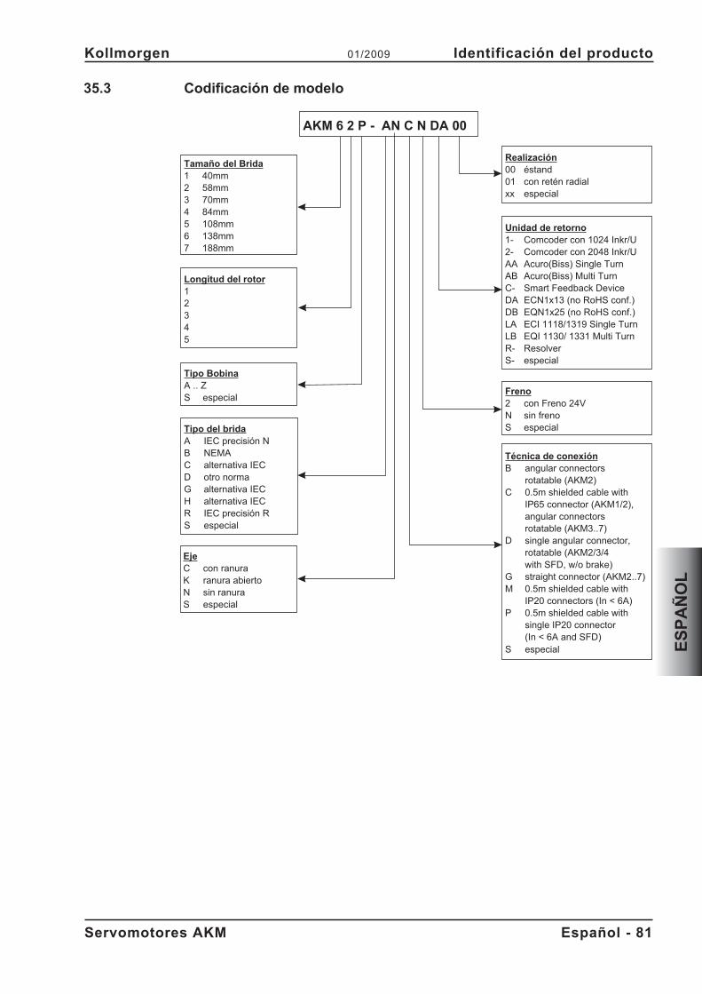
35.3 Codificación de modelo
Servomotores AKM Español - 81
Kollmorgen 01/2009 Identificación del producto
ES
PA
ÑO
L
Tamaño del Brida1 40mm2 58mm3 70mm4 84mm5 108mm6 138mm7 188mm
Tipo del bridaA IEC precisión NB NEMAC alternativa IECD otro normaG alternativa IECH alternativa IECR IEC precisión RS especial
Longitud del rotor12345
Tipo BobinaA .. ZS especial
Técnica de conexiónB angular connectors
rotatable (AKM2)C 0.5m shielded cable with
IP65 connector (AKM1/2),angular connectorsrotatable (AKM3..7)
D single angular connector,rotatable (AKM2/3/4with SFD, w/o brake)
G straight connector (AKM2..7)M 0.5m shielded cable with
IP20 connectors (In < 6A)P 0.5m shielded cable with
single IP20 connector(In < 6A and SFD)
S especial
Freno2 con Freno 24VN sin frenoS especial
Unidad de retorno1- Comcoder con 1024 Inkr/U2- Comcoder con 2048 Inkr/UAA Acuro(Biss) Single TurnAB Acuro(Biss) Multi TurnC- Smart Feedback DeviceDA ECN1x13 (no RoHS conf.)DB EQN1x25 (no RoHS conf.)LA ECI 1118/1319 Single TurnLB EQI 1130/ 1331 Multi TurnR- ResolverS- especial
Realización00 éstand01 con retén radialxx especial
AKM 6 2 P - AN C N DA 00
EjeC con ranuraK ranura abiertoN sin ranuraS especial
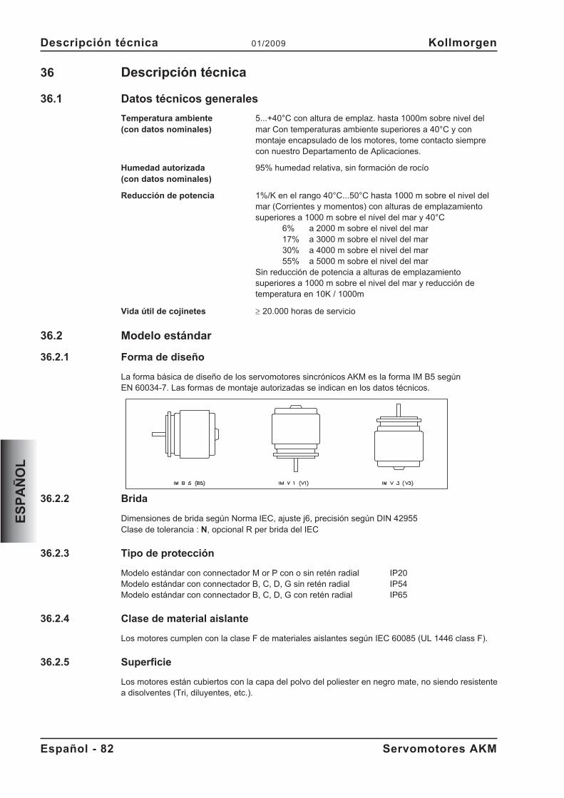
36 Descripción técnica
36.1 Datos técnicos generales
Temperatura ambiente 5...+40°C con altura de emplaz. hasta 1000m sobre nivel del(con datos nominales) mar Con temperaturas ambiente superiores a 40°C y con
montaje encapsulado de los motores, tome contacto siemprecon nuestro Departamento de Aplicaciones.
Humedad autorizada 95% humedad relativa, sin formación de rocío(con datos nominales)
Reducción de potencia 1%/K en el rango 40°C...50°C hasta 1000 m sobre el nivel delmar (Corrientes y momentos) con alturas de emplazamientosuperiores a 1000 m sobre el nivel del mar y 40°C
6% a 2000 m sobre el nivel del mar17% a 3000 m sobre el nivel del mar30% a 4000 m sobre el nivel del mar55% a 5000 m sobre el nivel del mar
Sin reducción de potencia a alturas de emplazamientosuperiores a 1000 m sobre el nivel del mar y reducción detemperatura en 10K / 1000m
Vida útil de cojinetes � 20.000 horas de servicio
36.2 Modelo estándar
36.2.1 Forma de diseño
La forma básica de diseño de los servomotores sincrónicos AKM es la forma IM B5 segúnEN 60034-7. Las formas de montaje autorizadas se indican en los datos técnicos.
36.2.2 Brida
Dimensiones de brida según Norma IEC, ajuste j6, precisión según DIN 42955Clase de tolerancia : N, opcional R per brida del IEC
36.2.3 Tipo de protección
Modelo estándar con connectador M or P con o sin retén radial IP20Modelo estándar con connectador B, C, D, G sin retén radial IP54Modelo estándar con connectador B, C, D, G con retén radial IP65
36.2.4 Clase de material aislante
Los motores cumplen con la clase F de materiales aislantes según IEC 60085 (UL 1446 class F).
36.2.5 Superficie
Los motores están cubiertos con la capa del polvo del poliester en negro mate, no siendo resistentea disolventes (Tri, diluyentes, etc.).
Español - 82 Servomotores AKM
Descripción técnica 01/2009 Kollmorgen
ES
PA
ÑO
L
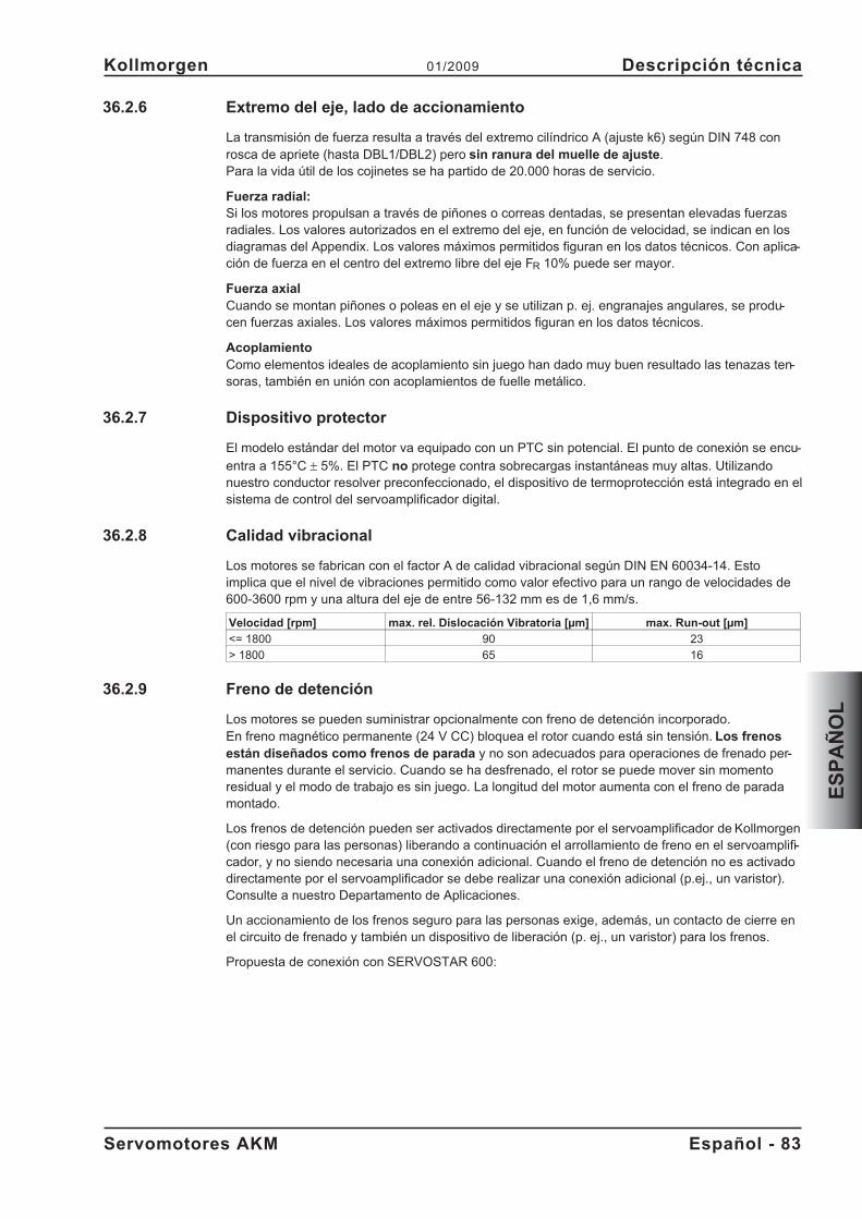
36.2.6 Extremo del eje, lado de accionamiento
La transmisión de fuerza resulta a través del extremo cilíndrico A (ajuste k6) según DIN 748 conrosca de apriete (hasta DBL1/DBL2) pero sin ranura del muelle de ajuste.Para la vida útil de los cojinetes se ha partido de 20.000 horas de servicio.
Fuerza radial:Si los motores propulsan a través de piñones o correas dentadas, se presentan elevadas fuerzasradiales. Los valores autorizados en el extremo del eje, en función de velocidad, se indican en losdiagramas del Appendix. Los valores máximos permitidos figuran en los datos técnicos. Con aplica-ción de fuerza en el centro del extremo libre del eje FR 10% puede ser mayor.
Fuerza axialCuando se montan piñones o poleas en el eje y se utilizan p. ej. engranajes angulares, se produ-cen fuerzas axiales. Los valores máximos permitidos figuran en los datos técnicos.
AcoplamientoComo elementos ideales de acoplamiento sin juego han dado muy buen resultado las tenazas ten-soras, también en unión con acoplamientos de fuelle metálico.
36.2.7 Dispositivo protector
El modelo estándar del motor va equipado con un PTC sin potencial. El punto de conexión se encu-
entra a 155°C � 5%. El PTC no protege contra sobrecargas instantáneas muy altas. Utilizandonuestro conductor resolver preconfeccionado, el dispositivo de termoprotección está integrado en elsistema de control del servoamplificador digital.
36.2.8 Calidad vibracional
Los motores se fabrican con el factor A de calidad vibracional según DIN EN 60034-14. Estoimplica que el nivel de vibraciones permitido como valor efectivo para un rango de velocidades de600-3600 rpm y una altura del eje de entre 56-132 mm es de 1,6 mm/s.
Velocidad [rpm] max. rel. Dislocación Vibratoria [µm] max. Run-out [µm]
<= 1800 90 23
> 1800 65 16
36.2.9 Freno de detención
Los motores se pueden suministrar opcionalmente con freno de detención incorporado.En freno magnético permanente (24 V CC) bloquea el rotor cuando está sin tensión. Los frenosestán diseñados como frenos de parada y no son adecuados para operaciones de frenado per-manentes durante el servicio. Cuando se ha desfrenado, el rotor se puede mover sin momentoresidual y el modo de trabajo es sin juego. La longitud del motor aumenta con el freno de paradamontado.
Los frenos de detención pueden ser activados directamente por el servoamplificador de Kollmorgen(con riesgo para las personas) liberando a continuación el arrollamiento de freno en el servoamplifi-cador, y no siendo necesaria una conexión adicional. Cuando el freno de detención no es activadodirectamente por el servoamplificador se debe realizar una conexión adicional (p.ej., un varistor).Consulte a nuestro Departamento de Aplicaciones.
Un accionamiento de los frenos seguro para las personas exige, además, un contacto de cierre enel circuito de frenado y también un dispositivo de liberación (p. ej., un varistor) para los frenos.
Propuesta de conexión con SERVOSTAR 600:
Servomotores AKM Español - 83
Kollmorgen 01/2009 Descripción técnica
ES
PA
ÑO
L
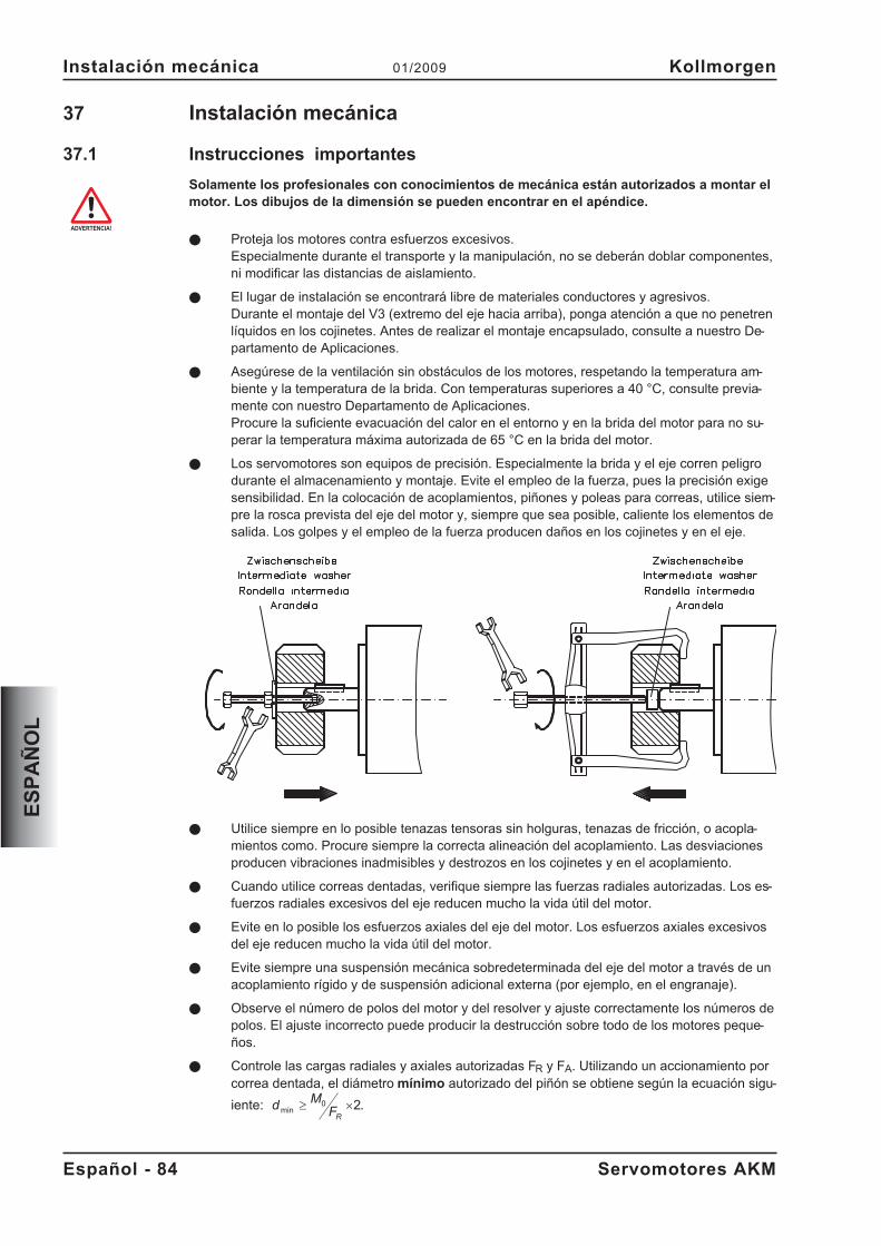
37 Instalación mecánica
37.1 Instrucciones importantes
Solamente los profesionales con conocimientos de mecánica están autorizados a montar elmotor. Los dibujos de la dimensión se pueden encontrar en el apéndice.
� Proteja los motores contra esfuerzos excesivos.Especialmente durante el transporte y la manipulación, no se deberán doblar componentes,ni modificar las distancias de aislamiento.
� El lugar de instalación se encontrará libre de materiales conductores y agresivos.Durante el montaje del V3 (extremo del eje hacia arriba), ponga atención a que no penetrenlíquidos en los cojinetes. Antes de realizar el montaje encapsulado, consulte a nuestro De-partamento de Aplicaciones.
� Asegúrese de la ventilación sin obstáculos de los motores, respetando la temperatura am-biente y la temperatura de la brida. Con temperaturas superiores a 40 °C, consulte previa-mente con nuestro Departamento de Aplicaciones.Procure la suficiente evacuación del calor en el entorno y en la brida del motor para no su-perar la temperatura máxima autorizada de 65 °C en la brida del motor.
� Los servomotores son equipos de precisión. Especialmente la brida y el eje corren peligrodurante el almacenamiento y montaje. Evite el empleo de la fuerza, pues la precisión exigesensibilidad. En la colocación de acoplamientos, piñones y poleas para correas, utilice siem-pre la rosca prevista del eje del motor y, siempre que sea posible, caliente los elementos desalida. Los golpes y el empleo de la fuerza producen daños en los cojinetes y en el eje.
� Utilice siempre en lo posible tenazas tensoras sin holguras, tenazas de fricción, o acopla-mientos como. Procure siempre la correcta alineación del acoplamiento. Las desviacionesproducen vibraciones inadmisibles y destrozos en los cojinetes y en el acoplamiento.
� Cuando utilice correas dentadas, verifique siempre las fuerzas radiales autorizadas. Los es-fuerzos radiales excesivos del eje reducen mucho la vida útil del motor.
� Evite en lo posible los esfuerzos axiales del eje del motor. Los esfuerzos axiales excesivosdel eje reducen mucho la vida útil del motor.
� Evite siempre una suspensión mecánica sobredeterminada del eje del motor a través de unacoplamiento rígido y de suspensión adicional externa (por ejemplo, en el engranaje).
� Observe el número de polos del motor y del resolver y ajuste correctamente los números depolos. El ajuste incorrecto puede producir la destrucción sobre todo de los motores peque-ños.
� Controle las cargas radiales y axiales autorizadas FR y FA. Utilizando un accionamiento porcorrea dentada, el diámetro mínimo autorizado del piñón se obtiene según la ecuación sigu-
iente: dM
FR
min � �0 2.
Español - 84 Servomotores AKM
Instalación mecánica 01/2009 Kollmorgen
ES
PA
ÑO
L
38 Instalación eléctrica
38.1 Instrucciones de seguridad
Solamente los profesionales con conocimientos de electrotecnia están autorizados a cable-ar el motor. Los esquemas eléctricos se pueden encontrar en el apéndice.
El montaje y cableado de los motores se realizará siempre sin tensión, es decir, ninguna delas tensiones de servicio del aparato a conectar deberá estar activada. Asegúrese de que ladesconexión del armario de distribución sea segura (bloqueo, rótulos de advertencia, etc.).Las diferentes tensiones se conectarán en la primera puesta en funcionamiento.
No manipule nunca las conexiones eléctricas de los motores cuando se encuentren bajotensión. Las cargas residuales en los condensadores del servoamplificador pueden presen-tar valores peligrosos incluso hasta 5 minutos después de desconectar de la red.Mida la tensión en el circuito intermedio y espere hasta que haya descendido por debajo de40 V. Las conexiones de control y de potencia pueden provocar tensión, incluso aunque elmotor no esté girando.
El símbolo de masa�, que se encuentra en todos los planos de conexión, indica quedebe asegurarse de realizar una conexión en el armario de distribución con la mayor super-ficie posible conductora de electricidad, entre el aparato que lleva la indicación y la placa demontaje. Esta conexión hará posible la derivación de interferencias de alta frecuencia y nodebe confundirse con la marca PE (medida de protección según EN 60204).Respete también las indicaciones en los planos de conexión de las Instrucciones de instala-ción y de puesta en funcionamiento del servoamplificador utilizado.
38.2 Guía de instalación eléctrica
� Compruebe la correspondencia entre el servoamplificador y el motor. Compare la tensiónnominal y la corriente nominal de los aparatos. Realice el cableado conforme al cuadro deconexiones de las Instrucciones de instalación y de puesta en funcionamiento del servoam-plificador. Las conexiones del motor se encuentran en la Appendixf.
� Asegúrese de que la toma de tierra del servoamplificador y del motor esté perfectamenteinstalada. Véanse la adecuada protección de compatibilidad electromagnética y de puesta atierra en las Instrucciones de instalación del servoamplificador utilizado. Ponga a tierra laplaca de montaje y el bloque del motor..
� Tienda los cables de potencia y de control suficientemente espaciados (distancia > 20 cm).Así mejorará la compatibilidad electromagnética del sistema. Utilizando un cale de potenciadel motor con conductores de mando de freno integrados, estos deberán estar apantallados.La pantalla estará dispuesta por ambos lados (véase manual de instalación del servoamplifi-cador).
� Cableado— Tienda los cables de potencia y de control bien separados— Conecte el resolver y el codificador— Conecte los cables del motor cerca del servoamplificador— Apantallamientos a ambos lados en bornes de protección o en el enchufe de
compatibilidad electromagnética— Conecta el freno de detención, si está montado.— Coloque el apantallamiento a ambos lados
� Realice el tendido de todos las conducciones de alta tensión con sección suficiente segúnEN 60204. En los datos técnicos se incluyen las secciones recomendadas.En función del tipo de servoamplificador utilizado, con cables de motor largos (> 25m) debe conectarse una bobina de motor (3YL) en el conductor del motor (véase elmanual de producto del servoamplificador y el manual de accesorios).
� Realice apantallamientos de gran superficie (baja resistencia) a través de cajas de enchufemetalizadas, o bien, de uniones de cable roscadas compatibles electromagnéticamente.
Servomotores AKM Español - 85
Kollmorgen 01/2009 Instalación eléctrica
ES
PA
ÑO
L
38.3 Conexión de los motores
� Realice el cableado cumpliendo los reglamentos y normas vigentes. Los esquemaseléctricos se pueden encontrar en el apéndice.
� Para las conexiones de potencia y de retorno, utilice exclusivamente nuestras con-ducciones preconfeccionadas y protegidas.
� Coloque los apantallamientos en la forma indicada en las figuras de las Instruccionesde instalación de los servoamplificadores.
� Los apantallamientos mal colocados producen siempre a interferencias electromag-néticas.
� La longitud máxima del conductor se define en el manual de producto del servoampli-ficador utilizado.
Requisitos al material de cables:
Capacidad
Cable del motor - menor que 150 pF/mCable Resolver - menor que 120 pF/m
Para una descripción detallada de cables premontados, refiera por favor a los manuales ac-cesorios.
Español - 86 Servomotores AKM
Instalación eléctrica 01/2009 Kollmorgen
ES
PA
ÑO
L
39 Puesta en funcionamento
39.1 Instrucciones importantes
Solamente los profesionales con amplios conocimientos de electrotecnia y de técnicas deaccionamiento están autorizados a la puesta en funcionamiento del conjunto servoamplifi-cador-motor.
Compruebe que todas las piezas de conexión que conducen tensión estén protegidas con-tra cualquier posible contacto. Se producen tensiones peligrosas de hasta 900V.
No manipule nunca las conexiones eléctricas de los motores cuando se encuentren bajotensión. Las cargas residuales en los condensadores del servoamplificador pueden presen-tar valores peligrosos incluso hasta 5 minutos después de desconectar de la red.
La temperatura de la superficie del motor puede alcanzar 100 °C durante el servicio. Com-pruebe (mida) la temperatura del motor. Espere a que la temperatura haya descendido a 40°C antes de tocar el motor con las manos.
Asegúrese de que, incluso con movimientos involuntarios del motor, no puedan existir peli-gros para las personas y para la máquina.
39.2 Guía de puesta en funcionamento
La forma de proceder en la puesta en accionamiento se describe a modo de ejemplo. Dependiendodel tipo de puesta en servicio de los aparatos puede ser adecuado o necesario un procedimiento uotro.
� Compruebe el montaje y la alineación del motor.
� Compruebe el firme asiento de los elementos de salida de fuerza (acoplamiento, engranaje,polea de la correa) así como el ajuste correcto (respetar las fuerzas radiales y axiales autori-zadas).
� Compruebe el cableado y las conexiones del motor y del servoamplificador. Compruebe lacorrecta puesta a tierra.
� Compruebe el funcionamiento del freno de detención, si está montado. (conectar 24V, el fre-no se debe soltar).
� Compruebe si el rotor del motor gira libremente (soltar primero el freno, si está montado).Compruebe si se escuchan ruidos de fricción.
� Compruebe si se han tomado todas las medidas de protección contra contactos para laspiezas móviles y las conductoras de tensión.
� Realice todas las comprobaciones específicas y necesarias para su equipo.
� Conforme a las Instrucciones de puesta en funcionamiento del servoamplificador, pongaahora en marcha el accionamiento.
� En sistemas de varios ejes, ponga en marcha, una a una, cada una de las unidades de ac-cionamiento servoamplificador-motor.
Servomotores AKM Español - 87
Kollmorgen 01/2009 Puesta en funcionamento
ES
PA
ÑO
L
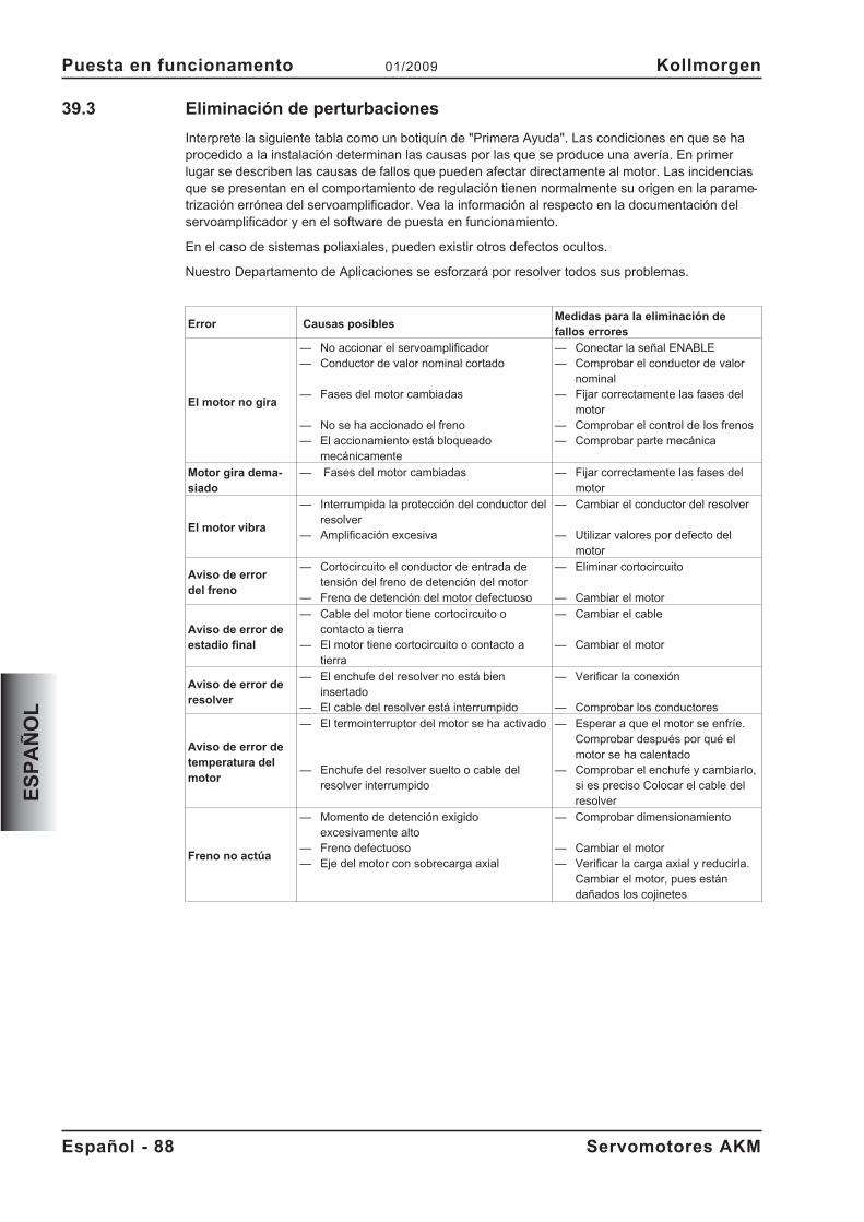
39.3 Eliminación de perturbaciones
Interprete la siguiente tabla como un botiquín de "Primera Ayuda". Las condiciones en que se haprocedido a la instalación determinan las causas por las que se produce una avería. En primerlugar se describen las causas de fallos que pueden afectar directamente al motor. Las incidenciasque se presentan en el comportamiento de regulación tienen normalmente su origen en la parame-trización errónea del servoamplificador. Vea la información al respecto en la documentación delservoamplificador y en el software de puesta en funcionamiento.
En el caso de sistemas poliaxiales, pueden existir otros defectos ocultos.
Nuestro Departamento de Aplicaciones se esforzará por resolver todos sus problemas.
Error Causas posiblesMedidas para la eliminación defallos errores
El motor no gira
— No accionar el servoamplificador— Conductor de valor nominal cortado
— Fases del motor cambiadas
— No se ha accionado el freno— El accionamiento está bloqueado
mecánicamente
— Conectar la señal ENABLE— Comprobar el conductor de valor
nominal— Fijar correctamente las fases del
motor— Comprobar el control de los frenos— Comprobar parte mecánica
Motor gira dema-siado
— Fases del motor cambiadas — Fijar correctamente las fases delmotor
El motor vibra
— Interrumpida la protección del conductor delresolver
— Amplificación excesiva
— Cambiar el conductor del resolver
— Utilizar valores por defecto delmotor
Aviso de errordel freno
— Cortocircuito el conductor de entrada detensión del freno de detención del motor
— Freno de detención del motor defectuoso
— Eliminar cortocircuito
— Cambiar el motor
Aviso de error deestadio final
— Cable del motor tiene cortocircuito ocontacto a tierra
— El motor tiene cortocircuito o contacto atierra
— Cambiar el cable
— Cambiar el motor
Aviso de error deresolver
— El enchufe del resolver no está bieninsertado
— El cable del resolver está interrumpido
— Verificar la conexión
— Comprobar los conductores
Aviso de error detemperatura delmotor
— El termointerruptor del motor se ha activado
— Enchufe del resolver suelto o cable delresolver interrumpido
— Esperar a que el motor se enfríe.Comprobar después por qué elmotor se ha calentado
— Comprobar el enchufe y cambiarlo,si es preciso Colocar el cable delresolver
Freno no actúa
— Momento de detención exigidoexcesivamente alto
— Freno defectuoso— Eje del motor con sobrecarga axial
— Comprobar dimensionamiento
— Cambiar el motor— Verificar la carga axial y reducirla.
Cambiar el motor, pues estándañados los cojinetes
Español - 88 Servomotores AKM
Puesta en funcionamento 01/2009 Kollmorgen
ES
PA
ÑO
L
40 Datos técnicos
Todos los datos válidos para la temperatura ambientales de 40°C y la temperatura excesiva de labobina 100K . Los datos pueden tener una tolerancia de el +/- 10%.
40.1 Definiciones
Par motor de parada M0 [Nm]El par motor de parada puede ser entregado durante un tiempo ilimitado desde un velocidad de0<n<100 min-1 y en condiciones ambientales nominales.
Par motor nominal Mn [Nm]El par motor nominal se entrega cuando el motor es alimentado con la corriente nominal a veloci-dad nominal. El par motor nominal puede ser entregado durante un tiempo ilimitado en serviciocontinuo (S1) al velocidad nominal.
Corriente de parada I0rms [A]La corriente de parada es el valor efectivo de la corriente sinusoidal que recibe el motor al0<n<100 min-1, para poder entregar el par motor de parada.
Corriente máxima (corriente pulsatoria) I0max [A]La corriente máxima (valor sinusoidal eficaz) es aproximadamente equivalente a 4-times la cor-riente de parada. El valor real es determinado por la corriente máxima del servoamplificador seutiliza que.
Constante de par motor KTrms [Nm/A]La constante indica el par motor en Nm que genera el motor con 1A de corriente efectiva sinusoi-dal. M=I x KT (hasta un máximo de I = 2 x I0)
Constante de tensión KErms [mVmin]La constante de tensión indica la fuerza electromotriz inducida del motor referida a 1000 r.p.m.como valor efectivo sinusoidal entre dos bornes.
Momento de inercia del rotor J [kgcm²]La constante J es una medida de la capacidad de aceleración del motor. Con I0 resulta, por ejem-plo, un tiempo de aceleración tb de 0 hasta 3000 min-1 :
t sM s
m
cmJ
b[ ] �
�
��
��
3000 2
60 100
2
4 2
�con M0 en Nm y J en kgcm²
Constante térmica de tiempo tth [min]La constante tth indica el tiempo de calentamiento del motor frío bajo carga con I0 hasta alcanzar0,63 x 105 Kelvin de sobretemperatura.Bajo carga con corriente máxima, el calentamiento tiene lugar en un tiempo mucho menor.
Tiempos de respuesta del freno tBRH [ms] / tBRL [ms]Las constantes indican los tiempos de reacción del freno de detención en funcionamiento con ten-sión nominal en el servoamplificador.
UN
Tensión nominal del red
Un
Tensión nominal del circuito intermedio U Un N
� �2
Servomotores AKM Español - 89
Kollmorgen 01/2009 Datos técnicos
ES
PA
ÑO
L
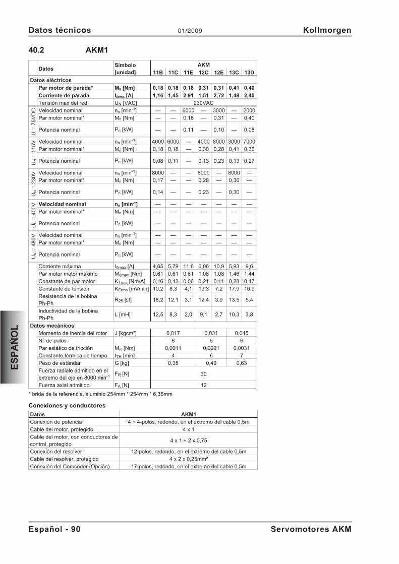
40.2 AKM1
DatosSímbolo[unidad]
AKM
11B 11C 11E 12C 12E 13C 13D
Datos eléctricos
Par motor de parada* M0 [Nm] 0,18 0,18 0,18 0,31 0,31 0,41 0,40
Corriente de parada I0rms [A] 1,16 1,45 2,91 1,51 2,72 1,48 2,40
Tensión max del red UN [VAC] 230VAC
U=
75
VD
C Velocidad nominal nn [min-1] — — 6000 — 3000 — 2000
Par motor nominal* Mn [Nm] — — 0,18 — 0,31 — 0,40
Potencia nominal Pn [kW] — — 0,11 — 0,10 — 0,08
UN
=1
15
V Velocidad nominal nn [min-1] 4000 6000 — 4000 8000 3000 7000
Par motor nominal* Mn [Nm] 0,18 0,18 — 0,30 0,28 0,41 0,36
Potencia nominal Pn [kW] 0,08 0,11 — 0,13 0,23 0,13 0,27
UN
=2
30
V Velocidad nominal nn [min-1] 8000 — — 8000 — 8000 —
Par motor nominal* Mn [Nm] 0,17 — — 0,28 — 0,36 —
Potencia nominal Pn [kW] 0,14 — — 0,23 — 0,30 —
UN
=4
00
V Velocidad nominal nn [min-1] — — — — — — —
Par motor nominal* Mn [Nm] — — — — — — —
Potencia nominal Pn [kW] — — — — — — —
UN
=4
80
V Velocidad nominal nn [min-1] — — — — — — —
Par motor nominal* Mn [Nm] — — — — — — —
Potencia nominal Pn [kW] — — — — — — —
Corriente máxima I0max [A] 4,65 5,79 11,6 6,06 10,9 5,93 9,6
Par motor motor máximo M0max [Nm] 0,61 0,61 0,61 1,08 1,08 1,46 1,44
Constante de par motor KTrms [Nm/A] 0,16 0,13 0,06 0,21 0,11 0,28 0,17
Constante de tensión KErms [mVmin] 10,2 8,3 4,1 13,3 7,2 17,9 10,9
Resistencia de la bobinaPh-Ph
R25 [] 18,2 12,1 3,1 12,4 3,9 13,5 5,4
Inductividad de la bobinaPh-Ph
L [mH] 12,5 8,3 2,0 9,1 2,7 10,3 3,8
Datos mecánicos
Momento de inercia del rotor J [kgcm²] 0,017 0,031 0,045
N° de polos 6 6 6
Par estático de fricción MR [Nm] 0,0011 0,0021 0,0031
Constante térmica de tiempo tTH [min] 4 6 7
Peso de estándar G [kg] 0,35 0,49 0,63
Fuerza radiale admitido en elextremo del eje en 8000 min-1 FR [N] 30
Fuerza axial admitido FA [N] 12
* brida de la referencia, aluminio 254mm * 254mm * 6,35mm
Conexiones y conductores
Datos AKM1
Conexión de potencia 4 + 4-polos, redondo, en el extremo del cable 0,5m
Cable del motor, protegido 4 x 1
Cable del motor, con conductores decontrol, protegido
4 x 1 + 2 x 0,75
Conexión del resolver 12-polos, redondo, en el extremo del cable 0,5m
Cable del resolver, protegido 4 x 2 x 0,25mm²
Conexión del Comcoder (Opción) 17-polos, redondo, en el extremo del cable 0,5m
Español - 90 Servomotores AKM
Datos técnicos 01/2009 Kollmorgen
ES
PA
ÑO
L
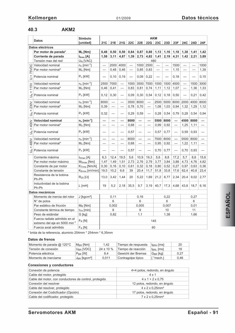
40.3 AKM2
DatosSímbolo[unidad]
AKM
21C 21E 21G 22C 22E 22G 23C 23D 23F 24C 24D 24F
Datos eléctricos
Par motor de parada* M0 [Nm] 0,48 0,50 0,50 0,84 0,87 0,88 1,13 1,16 1,18 1,38 1,41 1,42
Corriente de parada I0rms [A] 1,58 3,11 4,87 1,39 2,73 4,82 1,41 2,19 4,31 1,42 2,21 3,89
Tensión max del red UN [VAC] 480
U=
75
VD
C Velocidad nominal nn [min-1] — 2000 4000 — 1000 2500 — — 1500 — — 1000
Par motor nominal* Mn [Nm] — 0,48 0,46 — 0,85 0,83 — — 1,15 — — 1,39
Potencia nominal Pn [kW] — 0,10 0,19 — 0,09 0,22 — — 0,18 — — 0,15
UN
=1
15
V Velocidad nominal nn [min-1] 2500 7000 — 1000 3500 7000 1000 1500 4500 — 1500 3000
Par motor nominal* Mn [Nm] 0,46 0,41 — 0,83 0,81 0,74 1,11 1,12 1,07 — 1,36 1,33
Potencia nominal Pn [kW] 0,12 0,30 — 0,09 0,30 0,54 0,12 0,18 0,50 — 0,21 0,42
UN
=2
30
V Velocidad nominal nn [min-1] 8000 — — 3500 8000 — 2500 5000 8000 2000 4000 8000
Par motor nominal* Mn [Nm] 0,39 — — 0,78 0,70 — 1,08 1,03 0,94 1,32 1,29 1,12
Potencia nominal Pn [kW] 0,32 — — 0,29 0,59 — 0,28 0,54 0,79 0,28 0,54 0,94
UN
=4
00
V Velocidad nominal nn [min-1] — — — 8000 — — 5500 8000 — 4500 8000 —
Par motor nominal* Mn [Nm] — — — 0,68 — — 0,99 0,92 — 1,25 1,11 —
Potencia nominal Pn [kW] — — — 0,57 — — 0,57 0,77 — 0,59 0,93 —
UN
=4
80
V Velocidad nominal nn [min-1] — — — 8000 — — 7000 8000 — 5500 8000 —
Par motor nominal* Mn [Nm] — — — 0,68 — — 0,95 0,92 — 1,22 1,11 —
Potencia nominal Pn [kW] — — — 0,57 — — 0,70 0,77 — 0,70 0,93 —
Corriente máxima I0max [A] 6,3 12,4 19,5 5,6 10,9 19,3 5,6 8,8 17,2 5,7 8,8 15,6
Par motor motor máximo M0max [Nm] 1,47 1,49 1,51 2,73 2,76 2,79 3,77 3,84 3,88 4,73 4,76 4,82
Constante de par motor KTrms [Nm/A] 0,30 0,16 0,10 0,61 0,32 0,18 0,80 0,52 0,27 0,97 0,63 0,36
Constante de tensión KErms [mVmin] 19,5 10,2 6,6 39 20,4 11,7 51,8 33,8 17,6 62,4 40,8 23,4
Resistencia de la bobinaPh-Ph
R25 [] 13,0 3,42 1,44 20 5,22 1,69 21,2 8,77 2,34 20,4 9,02 2,77
Inductividad de la bobinaPh-Ph
L [mH] 19 5,2 2,18 35,5 9,7 3,19 40,7 17,3 4,68 43,8 18,7 6,16
Datos mecánicos
Momento de inercia del rotor J [kgcm²] 0,11 0,16 0,22 0,27
N° de polos 6 6 6 6
Par estático de fricción MR [Nm] 0,002 0,005 0,007 0,01
Constante térmica de tiempo tTH [min] 8 9 10 11
Peso de estándar G [kg] 0,82 1,1 1,38 1,66
Fuerza radiale admitido en elextremo del eje en 5000 min-1 FR [N] 145
Fuerza axial admitido FA [N] 60
* brida de la referencia, aluminio 254mm * 254mm * 6,35mm
Datos de frenos
Momento de parada @ 120°C MBR [Nm] 1,42 Tiempo de respuesta tBRH [ms] 20
Tensión de conexión UBR [VDC] 24 ± 10 % Tiempo de reacción tBRL [ms] 18
Potencia eléctrica PBR [W] 8,4 Gewicht der Bremse GBR [kg] 0,27
Momento de inerciame JBR [kgcm²] 0,011 Contragolpe típico [ °mech.] 0,46
Conexiones y conductores
Conexión de potencia 4+4 polos, redondo, en ángulo
Cable del motor, protegido 4 x 1
Cable del motor, con conductores de control, protegido 4 x 1 + 2 x 0,75
Conexión del resolver 12 polos, redondo, en ángulo
Cable del resolver, protegido 4 x 2 x 0,25mm²
Conexión del Codicficador (Opción) 17 polos, redondo, en ángulo
Cable del codificador, protegido 7 x 2 x 0,25mm²
Servomotores AKM Español - 91
Kollmorgen 01/2009 Datos técnicos
ES
PA
ÑO
L
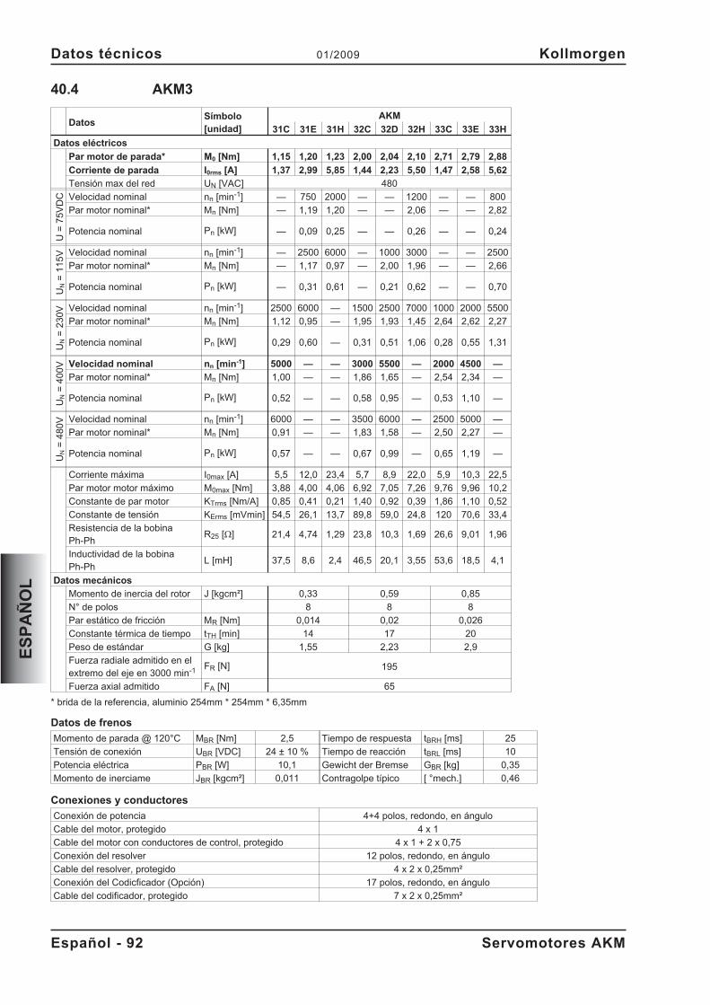
40.4 AKM3
DatosSímbolo[unidad]
AKM
31C 31E 31H 32C 32D 32H 33C 33E 33H
Datos eléctricos
Par motor de parada* M0 [Nm] 1,15 1,20 1,23 2,00 2,04 2,10 2,71 2,79 2,88
Corriente de parada I0rms [A] 1,37 2,99 5,85 1,44 2,23 5,50 1,47 2,58 5,62
Tensión max del red UN [VAC] 480
U=
75
VD
C Velocidad nominal nn [min-1] — 750 2000 — — 1200 — — 800
Par motor nominal* Mn [Nm] — 1,19 1,20 — — 2,06 — — 2,82
Potencia nominal Pn [kW] — 0,09 0,25 — — 0,26 — — 0,24
UN
=1
15
V Velocidad nominal nn [min-1] — 2500 6000 — 1000 3000 — — 2500
Par motor nominal* Mn [Nm] — 1,17 0,97 — 2,00 1,96 — — 2,66
Potencia nominal Pn [kW] — 0,31 0,61 — 0,21 0,62 — — 0,70
UN
=2
30
V Velocidad nominal nn [min-1] 2500 6000 — 1500 2500 7000 1000 2000 5500
Par motor nominal* Mn [Nm] 1,12 0,95 — 1,95 1,93 1,45 2,64 2,62 2,27
Potencia nominal Pn [kW] 0,29 0,60 — 0,31 0,51 1,06 0,28 0,55 1,31
UN
=4
00
V Velocidad nominal nn [min-1] 5000 — — 3000 5500 — 2000 4500 —
Par motor nominal* Mn [Nm] 1,00 — — 1,86 1,65 — 2,54 2,34 —
Potencia nominal Pn [kW] 0,52 — — 0,58 0,95 — 0,53 1,10 —
UN
=4
80
V Velocidad nominal nn [min-1] 6000 — — 3500 6000 — 2500 5000 —
Par motor nominal* Mn [Nm] 0,91 — — 1,83 1,58 — 2,50 2,27 —
Potencia nominal Pn [kW] 0,57 — — 0,67 0,99 — 0,65 1,19 —
Corriente máxima I0max [A] 5,5 12,0 23,4 5,7 8,9 22,0 5,9 10,3 22,5
Par motor motor máximo M0max [Nm] 3,88 4,00 4,06 6,92 7,05 7,26 9,76 9,96 10,2
Constante de par motor KTrms [Nm/A] 0,85 0,41 0,21 1,40 0,92 0,39 1,86 1,10 0,52
Constante de tensión KErms [mVmin] 54,5 26,1 13,7 89,8 59,0 24,8 120 70,6 33,4
Resistencia de la bobinaPh-Ph
R25 [] 21,4 4,74 1,29 23,8 10,3 1,69 26,6 9,01 1,96
Inductividad de la bobinaPh-Ph
L [mH] 37,5 8,6 2,4 46,5 20,1 3,55 53,6 18,5 4,1
Datos mecánicos
Momento de inercia del rotor J [kgcm²] 0,33 0,59 0,85
N° de polos 8 8 8
Par estático de fricción MR [Nm] 0,014 0,02 0,026
Constante térmica de tiempo tTH [min] 14 17 20
Peso de estándar G [kg] 1,55 2,23 2,9
Fuerza radiale admitido en elextremo del eje en 3000 min-1 FR [N] 195
Fuerza axial admitido FA [N] 65
* brida de la referencia, aluminio 254mm * 254mm * 6,35mm
Datos de frenos
Momento de parada @ 120°C MBR [Nm] 2,5 Tiempo de respuesta tBRH [ms] 25
Tensión de conexión UBR [VDC] 24 ± 10 % Tiempo de reacción tBRL [ms] 10
Potencia eléctrica PBR [W] 10,1 Gewicht der Bremse GBR [kg] 0,35
Momento de inerciame JBR [kgcm²] 0,011 Contragolpe típico [ °mech.] 0,46
Conexiones y conductores
Conexión de potencia 4+4 polos, redondo, en ángulo
Cable del motor, protegido 4 x 1
Cable del motor con conductores de control, protegido 4 x 1 + 2 x 0,75
Conexión del resolver 12 polos, redondo, en ángulo
Cable del resolver, protegido 4 x 2 x 0,25mm²
Conexión del Codicficador (Opción) 17 polos, redondo, en ángulo
Cable del codificador, protegido 7 x 2 x 0,25mm²
Español - 92 Servomotores AKM
Datos técnicos 01/2009 Kollmorgen
ES
PA
ÑO
L
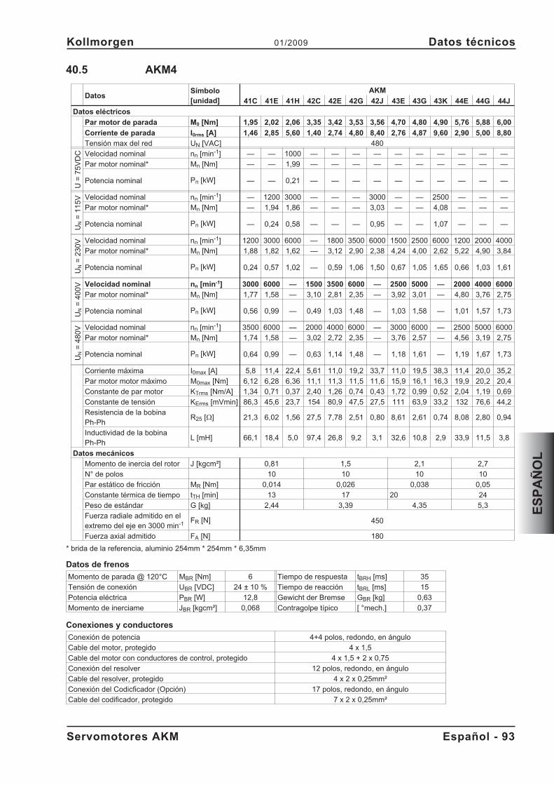
40.5 AKM4
DatosSímbolo[unidad]
AKM
41C 41E 41H 42C 42E 42G 42J 43E 43G 43K 44E 44G 44J
Datos eléctricos
Par motor de parada M0 [Nm] 1,95 2,02 2,06 3,35 3,42 3,53 3,56 4,70 4,80 4,90 5,76 5,88 6,00
Corriente de parada I0rms [A] 1,46 2,85 5,60 1,40 2,74 4,80 8,40 2,76 4,87 9,60 2,90 5,00 8,80
Tensión max del red UN [VAC] 480
U=
75
VD
C Velocidad nominal nn [min-1] — — 1000 — — — — — — — — — —
Par motor nominal* Mn [Nm] — — 1,99 — — — — — — — — — —
Potencia nominal Pn [kW] — — 0,21 — — — — — — — — — —
UN
=1
15
V Velocidad nominal nn [min-1] — 1200 3000 — — — 3000 — — 2500 — — —
Par motor nominal* Mn [Nm] — 1,94 1,86 — — — 3,03 — — 4,08 — — —
Potencia nominal Pn [kW] — 0,24 0,58 — — — 0,95 — — 1,07 — — —
UN
=2
30
V Velocidad nominal nn [min-1] 1200 3000 6000 — 1800 3500 6000 1500 2500 6000 1200 2000 4000
Par motor nominal* Mn [Nm] 1,88 1,82 1,62 — 3,12 2,90 2,38 4,24 4,00 2,62 5,22 4,90 3,84
Potencia nominal Pn [kW] 0,24 0,57 1,02 — 0,59 1,06 1,50 0,67 1,05 1,65 0,66 1,03 1,61
UN
=4
00
V Velocidad nominal nn [min-1] 3000 6000 — 1500 3500 6000 — 2500 5000 — 2000 4000 6000
Par motor nominal* Mn [Nm] 1,77 1,58 — 3,10 2,81 2,35 — 3,92 3,01 — 4,80 3,76 2,75
Potencia nominal Pn [kW] 0,56 0,99 — 0,49 1,03 1,48 — 1,03 1,58 — 1,01 1,57 1,73
UN
=4
80
V Velocidad nominal nn [min-1] 3500 6000 — 2000 4000 6000 — 3000 6000 — 2500 5000 6000
Par motor nominal* Mn [Nm] 1,74 1,58 — 3,02 2,72 2,35 — 3,76 2,57 — 4,56 3,19 2,75
Potencia nominal Pn [kW] 0,64 0,99 — 0,63 1,14 1,48 — 1,18 1,61 — 1,19 1,67 1,73
Corriente máxima I0max [A] 5,8 11,4 22,4 5,61 11,0 19,2 33,7 11,0 19,5 38,3 11,4 20,0 35,2
Par motor motor máximo M0max [Nm] 6,12 6,28 6,36 11,1 11,3 11,5 11,6 15,9 16,1 16,3 19,9 20,2 20,4
Constante de par motor KTrms [Nm/A] 1,34 0,71 0,37 2,40 1,26 0,74 0,43 1,72 0,99 0,52 2,04 1,19 0,69
Constante de tensión KErms [mVmin] 86,3 45,6 23,7 154 80,9 47,5 27,5 111 63,9 33,2 132 76,6 44,2
Resistencia de la bobinaPh-Ph
R25 [] 21,3 6,02 1,56 27,5 7,78 2,51 0,80 8,61 2,61 0,74 8,08 2,80 0,94
Inductividad de la bobinaPh-Ph
L [mH] 66,1 18,4 5,0 97,4 26,8 9,2 3,1 32,6 10,8 2,9 33,9 11,5 3,8
Datos mecánicos
Momento de inercia del rotor J [kgcm²] 0,81 1,5 2,1 2,7
N° de polos 10 10 10 10
Par estático de fricción MR [Nm] 0,014 0,026 0,038 0,05
Constante térmica de tiempo tTH [min] 13 17 20 24
Peso de estándar G [kg] 2,44 3,39 4,35 5,3
Fuerza radiale admitido en elextremo del eje en 3000 min-1 FR [N] 450
Fuerza axial admitido FA [N] 180
* brida de la referencia, aluminio 254mm * 254mm * 6,35mm
Datos de frenos
Momento de parada @ 120°C MBR [Nm] 6 Tiempo de respuesta tBRH [ms] 35
Tensión de conexión UBR [VDC] 24 ± 10 % Tiempo de reacción tBRL [ms] 15
Potencia eléctrica PBR [W] 12,8 Gewicht der Bremse GBR [kg] 0,63
Momento de inerciame JBR [kgcm²] 0,068 Contragolpe típico [ °mech.] 0,37
Conexiones y conductores
Conexión de potencia 4+4 polos, redondo, en ángulo
Cable del motor, protegido 4 x 1,5
Cable del motor con conductores de control, protegido 4 x 1,5 + 2 x 0,75
Conexión del resolver 12 polos, redondo, en ángulo
Cable del resolver, protegido 4 x 2 x 0,25mm²
Conexión del Codicficador (Opción) 17 polos, redondo, en ángulo
Cable del codificador, protegido 7 x 2 x 0,25mm²
Servomotores AKM Español - 93
Kollmorgen 01/2009 Datos técnicos
ES
PA
ÑO
L
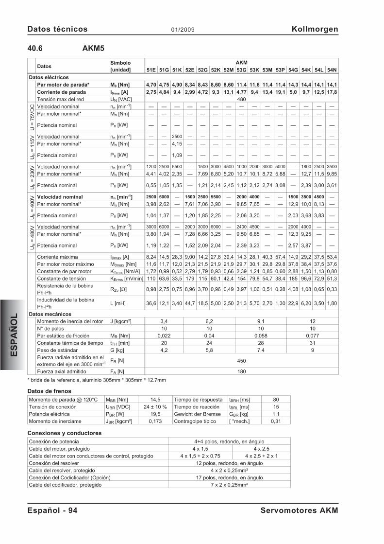
40.6 AKM5
DatosSímbolo[unidad]
AKM
51E 51G 51K 52E 52G 52K 52M 53G 53K 53M 53P 54G 54K 54L 54N
Datos eléctricos
Par motor de parada* M0 [Nm] 4,70 4,75 4,90 8,34 8,43 8,60 8,60 11,4 11,6 11,4 11,4 14,3 14,4 14,1 14,1
Corriente de parada I0rms [A] 2,75 4,84 9,4 2,99 4,72 9,3 13,1 4,77 9,4 13,4 19,1 5,0 9,7 12,5 17,8
Tensión max del red UN [VAC] 480
U=
75
VD
C Velocidad nominal nn [min-1] — — — — — — — — — — — — — — —
Par motor nominal* Mn [Nm] — — — — — — — — — — — — — — —
Potencia nominal Pn [kW] — — — — — — — — — — — — — — —
UN
=1
15
V Velocidad nominal nn [min-1] — — 2500 — — — — — — — — — — — —
Par motor nominal* Mn [Nm] — — 4,15 — — — — — — — — — — — —
Potencia nominal Pn [kW] — — 1,09 — — — — — — — — — — — —
UN
=2
30
V Velocidad nominal nn [min-1] 1200 2500 5500 — 1500 3000 4500 1000 2000 3000 5000 — 1800 2500 3500
Par motor nominal* Mn [Nm] 4,41 4,02 2,35 — 7,69 6,80 5,20 10,7 10,1 8,72 5,88 — 12,7 11,5 9,85
Potencia nominal Pn [kW] 0,55 1,05 1,35 — 1,21 2,14 2,45 1,12 2,12 2,74 3,08 — 2,39 3,00 3,61
UN
=4
00
V Velocidad nominal nn [min-1] 2500 5000 — 1500 2500 5500 — 2000 4000 — — 1500 3500 4500 —
Par motor nominal* Mn [Nm] 3,98 2,62 — 7,61 7,06 3,90 — 9,85 7,65 — — 12,9 10,0 8,13 —
Potencia nominal Pn [kW] 1,04 1,37 — 1,20 1,85 2,25 — 2,06 3,20 — — 2,03 3,68 3,83 —
UN
=4
80
V Velocidad nominal nn [min-1] 3000 6000 — 2000 3000 6000 — 2400 4500 — — 2000 4000 — —
Par motor nominal* Mn [Nm] 3,80 1,94 — 7,28 6,66 3,25 — 9,50 6,85 — — 12,3 9,25 — —
Potencia nominal Pn [kW] 1,19 1,22 — 1,52 2,09 2,04 — 2,39 3,23 — — 2,57 3,87 — —
Corriente máxima I0max [A] 8,24 14,5 28,3 9,00 14,2 27,8 39,4 14,3 28,1 40,3 57,4 14,9 29,2 37,5 53,4
Par motor motor máximo M0max [Nm] 11,6 11,7 12,0 21,3 21,5 21,9 21,9 29,7 30,1 29,8 29,8 37,8 38,4 37,5 37,6
Constante de par motor KTrms [Nm/A] 1,72 0,99 0,52 2,79 1,79 0,93 0,66 2,39 1,24 0,85 0,60 2,88 1,50 1,13 0,80
Constante de tensión KErms [mVmin] 110 63,6 33,5 179 115 60,1 42,4 154 79,8 54,7 38,4 185 96,6 72,9 51,3
Resistencia de la bobinaPh-Ph
R25 [] 8,98 2,75 0,75 8,96 3,70 0,96 0,49 3,97 1,06 0,51 0,28 4,08 1,08 0,65 0,33
Inductividad de la bobinaPh-Ph
L [mH] 36,6 12,1 3,40 44,7 18,5 5,00 2,50 21,3 5,70 2,70 1,30 22,9 6,20 3,50 1,80
Datos mecánicos
Momento de inercia del rotor J [kgcm²] 3,4 6,2 9,1 12
N° de polos 10 10 10 10
Par estático de fricción MR [Nm] 0,022 0,04 0,058 0,077
Constante térmica de tiempo tTH [min] 20 24 28 31
Peso de estándar G [kg] 4,2 5,8 7,4 9
Fuerza radiale admitido en elextremo del eje en 3000 min-1 FR [N] 450
Fuerza axial admitido FA [N] 180
* brida de la referencia, aluminio 305mm * 305mm * 12.7mm
Datos de frenos
Momento de parada @ 120°C MBR [Nm] 14,5 Tiempo de respuesta tBRH [ms] 80
Tensión de conexión UBR [VDC] 24 ± 10 % Tiempo de reacción tBRL [ms] 15
Potencia eléctrica PBR [W] 19,5 Gewicht der Bremse GBR [kg] 1,1
Momento de inerciame JBR [kgcm²] 0,173 Contragolpe típico [ °mech.] 0,31
Conexiones y conductores
Conexión de potencia 4+4 polos, redondo, en ángulo
Cable del motor, protegido 4 x 1,5 4 x 2,5
Cable del motor con conductores de control, protegido 4 x 1,5 + 2 x 0,75 4 x 2,5 + 2 x 1
Conexión del resolver 12 polos, redondo, en ángulo
Cable del resolver, protegido 4 x 2 x 0,25mm²
Conexión del Codicficador (Opción) 17 polos, redondo, en ángulo
Cable del codificador, protegido 7 x 2 x 0,25mm²
Español - 94 Servomotores AKM
Datos técnicos 01/2009 Kollmorgen
ES
PA
ÑO
L
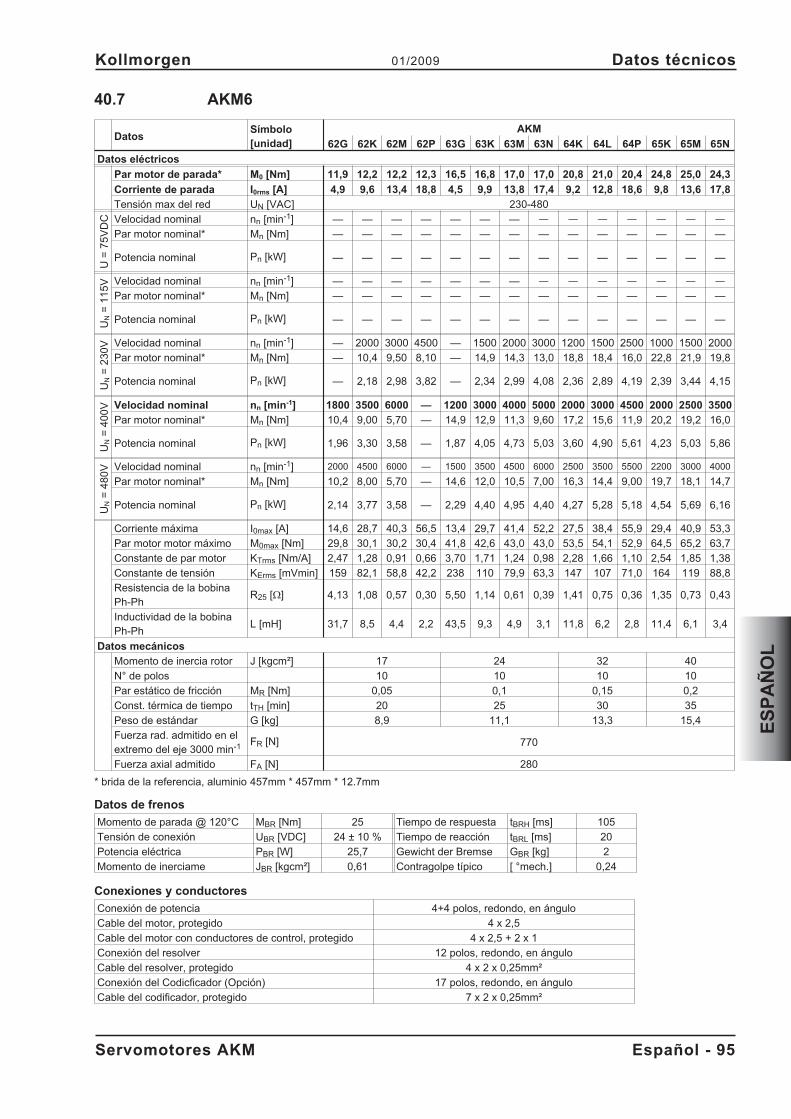
40.7 AKM6
DatosSímbolo[unidad]
AKM
62G 62K 62M 62P 63G 63K 63M 63N 64K 64L 64P 65K 65M 65N
Datos eléctricos
Par motor de parada* M0 [Nm] 11,9 12,2 12,2 12,3 16,5 16,8 17,0 17,0 20,8 21,0 20,4 24,8 25,0 24,3
Corriente de parada I0rms [A] 4,9 9,6 13,4 18,8 4,5 9,9 13,8 17,4 9,2 12,8 18,6 9,8 13,6 17,8
Tensión max del red UN [VAC] 230-480
U=
75
VD
C Velocidad nominal nn [min-1] — — — — — — — — — — — — — —
Par motor nominal* Mn [Nm] — — — — — — — — — — — — — —
Potencia nominal Pn [kW] — — — — — — — — — — — — — —
UN
=1
15
V Velocidad nominal nn [min-1] — — — — — — — — — — — — — —
Par motor nominal* Mn [Nm] — — — — — — — — — — — — — —
Potencia nominal Pn [kW] — — — — — — — — — — — — — —
UN
=2
30
V Velocidad nominal nn [min-1] — 2000 3000 4500 — 1500 2000 3000 1200 1500 2500 1000 1500 2000
Par motor nominal* Mn [Nm] — 10,4 9,50 8,10 — 14,9 14,3 13,0 18,8 18,4 16,0 22,8 21,9 19,8
Potencia nominal Pn [kW] — 2,18 2,98 3,82 — 2,34 2,99 4,08 2,36 2,89 4,19 2,39 3,44 4,15
UN
=4
00
V Velocidad nominal nn [min-1] 1800 3500 6000 — 1200 3000 4000 5000 2000 3000 4500 2000 2500 3500
Par motor nominal* Mn [Nm] 10,4 9,00 5,70 — 14,9 12,9 11,3 9,60 17,2 15,6 11,9 20,2 19,2 16,0
Potencia nominal Pn [kW] 1,96 3,30 3,58 — 1,87 4,05 4,73 5,03 3,60 4,90 5,61 4,23 5,03 5,86
UN
=4
80
V Velocidad nominal nn [min-1] 2000 4500 6000 — 1500 3500 4500 6000 2500 3500 5500 2200 3000 4000
Par motor nominal* Mn [Nm] 10,2 8,00 5,70 — 14,6 12,0 10,5 7,00 16,3 14,4 9,00 19,7 18,1 14,7
Potencia nominal Pn [kW] 2,14 3,77 3,58 — 2,29 4,40 4,95 4,40 4,27 5,28 5,18 4,54 5,69 6,16
Corriente máxima I0max [A] 14,6 28,7 40,3 56,5 13,4 29,7 41,4 52,2 27,5 38,4 55,9 29,4 40,9 53,3
Par motor motor máximo M0max [Nm] 29,8 30,1 30,2 30,4 41,8 42,6 43,0 43,0 53,5 54,1 52,9 64,5 65,2 63,7
Constante de par motor KTrms [Nm/A] 2,47 1,28 0,91 0,66 3,70 1,71 1,24 0,98 2,28 1,66 1,10 2,54 1,85 1,38
Constante de tensión KErms [mVmin] 159 82,1 58,8 42,2 238 110 79,9 63,3 147 107 71,0 164 119 88,8
Resistencia de la bobinaPh-Ph
R25 [] 4,13 1,08 0,57 0,30 5,50 1,14 0,61 0,39 1,41 0,75 0,36 1,35 0,73 0,43
Inductividad de la bobinaPh-Ph
L [mH] 31,7 8,5 4,4 2,2 43,5 9,3 4,9 3,1 11,8 6,2 2,8 11,4 6,1 3,4
Datos mecánicos
Momento de inercia rotor J [kgcm²] 17 24 32 40
N° de polos 10 10 10 10
Par estático de fricción MR [Nm] 0,05 0,1 0,15 0,2
Const. térmica de tiempo tTH [min] 20 25 30 35
Peso de estándar G [kg] 8,9 11,1 13,3 15,4
Fuerza rad. admitido en elextremo del eje 3000 min-1 FR [N] 770
Fuerza axial admitido FA [N] 280
* brida de la referencia, aluminio 457mm * 457mm * 12.7mm
Datos de frenos
Momento de parada @ 120°C MBR [Nm] 25 Tiempo de respuesta tBRH [ms] 105
Tensión de conexión UBR [VDC] 24 ± 10 % Tiempo de reacción tBRL [ms] 20
Potencia eléctrica PBR [W] 25,7 Gewicht der Bremse GBR [kg] 2
Momento de inerciame JBR [kgcm²] 0,61 Contragolpe típico [ °mech.] 0,24
Conexiones y conductores
Conexión de potencia 4+4 polos, redondo, en ángulo
Cable del motor, protegido 4 x 2,5
Cable del motor con conductores de control, protegido 4 x 2,5 + 2 x 1
Conexión del resolver 12 polos, redondo, en ángulo
Cable del resolver, protegido 4 x 2 x 0,25mm²
Conexión del Codicficador (Opción) 17 polos, redondo, en ángulo
Cable del codificador, protegido 7 x 2 x 0,25mm²
Servomotores AKM Español - 95
Kollmorgen 01/2009 Datos técnicos
ES
PA
ÑO
L
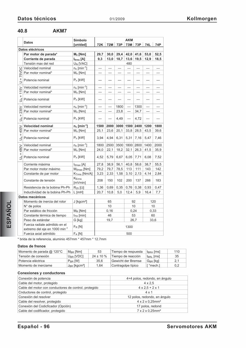
40.8 AKM7
DatosSímbolo[unidad]
AKM
72K 72M 72P 73M 73P 74L 74P
Datos eléctricos
Par motor de parada* M0 [Nm] 29,7 30,0 29,4 42,0 41,6 53,0 52,5
Corriente de parada I0rms [A] 9,3 13,0 18,7 13,6 19,5 12,9 18,5
Tensión max del red UN [VAC] 480
U=
75
VD
C Velocidad nominal nn [min-1] — — — — — — —
Par motor nominal* Mn [Nm] — — — — — — —
Potencia nominal Pn [kW] — — — — — — —
UN
=1
15
V Velocidad nominal nn [min-1] — — — — — — —
Par motor nominal* Mn [Nm] — — — — — — —
Potencia nominal Pn [kW] — — — — — — —
UN
=2
30
V Velocidad nominal nn [min-1] — — 1800 — 1300 — —
Par motor nominal* Mn [Nm] — — 23,8 — 34,7 — —
Potencia nominal Pn [kW] — — 4,49 — 4,72 — —
UN
=4
00
V Velocidad nominal nn [min-1] 1500 2000 3000 1500 2400 1200 1800
Par motor nominal* Mn [Nm] 25,1 23,6 20,1 33,8 28,5 43,5 39,6
Potencia nominal Pn [kW] 3,94 4,94 6,31 5,31 7,16 5,47 7,46
UN
=4
80
V Velocidad nominal nn [min-1] 1800 2500 3500 1800 2800 1400 2000
Par motor nominal* Mn [Nm] 24,0 22,1 18,2 32,1 26,3 41,5 35,9
Potencia nominal Pn [kW] 4,52 5,79 6,67 6,05 7,71 6,08 7,52
Corriente máxima I0max [A] 27,8 38,9 56,1 40,8 58,6 38,7 55,5
Par motor motor máximo M0max [Nm] 79,2 79,7 78,5 113 111 143 142
Constante de par motor KTrms [Nm/A] 3,23 2,33 1,58 3,10 2,13 4,14 2,84
Constante de tensiónKErms
[mVmin]208 150 102 200 137 266 183
Resistencia de la bobina Ph-Ph R25 [] 1,36 0,69 0,35 0,76 0,38 0,93 0,47
Inductividad de la bobina Ph-Ph L [mH] 20,7 10,8 5,0 12,4 5,9 16,4 7,7
Datos mecánicos
Momento de inercia del rotor J [kgcm²] 65 92 120
N° de polos 10 10 10
Par estático de fricción MR [Nm] 0,16 0,24 0,33
Constante térmica de tiempo tTH [min] 46 53 60
Peso de estándar G [kg] 19,7 26,7 33,6
Fuerza radiale admitido en elextremo del eje en 1000 min-1 FR [N] 1300
Fuerza axial admitido FA [N] 500
* brida de la referencia, aluminio 457mm * 457mm * 12.7mm
Datos de frenos
Momento de parada @ 120°C MBR [Nm] 53 Tiempo de respuesta tBRH [ms] 110
Tensión de conexión UBR [VDC] 24 ± 10 % Tiempo de reacción tBRL [ms] 35
Potencia eléctrica PBR [W] 35,6 Gewicht der Bremse GBR [kg] 2,1
Momento de inerciame JBR [kgcm²] 1,64 Contragolpe típico [ °mech.] 0,2
Conexiones y conductores
Conexión de potencia 4+4 polos, redondo, en ángulo
Cable del motor, protegido 4 x 2,5
Cable del motor con conductores de control, protegido 4 x 2,5 + 2 x 1
Cnductores de control, protegido 4 x 1
Conexión del resolver 12 polos, redondo, en ángulo
Cable del resolver, protegido 4 x 2 x 0,25mm²
Conexión del Codicficador (Opción) 17 polos, redond
Cable del codificador, protegido 7 x 2 x 0,25mm²
Español - 96 Servomotores AKM
Datos técnicos 01/2009 Kollmorgen
ES
PA
ÑO
L
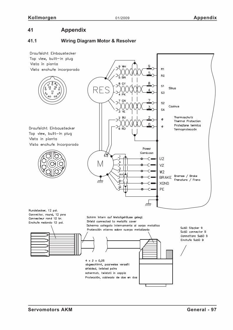
41 Appendix
41.1 Wiring Diagram Motor & Resolver
Servomotors AKM General - 97
Kollmorgen 01/2009 Appendix
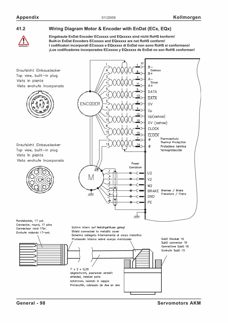
41.2 Wiring Diagram Motor & Encoder with EnDat (ECx, EQx)
Eingebaute EnDat Encoder ECxxxxx und EQxxxxx sind nicht RoHS konform!Built-in EnDat Encoders ECxxxxx and EQxxxxx are not RoHS conform!I codificatori incorporati ECxxxxx e EQxxxxx di EnDat non sono RoHS si conformano!¡Los codificadores incorporados ECxxxxx y EQxxxxx de EnDat no son RoHS conforman!
General - 98 Servomotors AKM
Appendix 01/2009 Kollmorgen
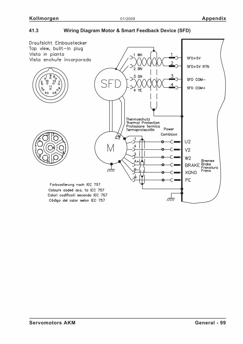
41.3 Wiring Diagram Motor & Smart Feedback Device (SFD)
Servomotors AKM General - 99
Kollmorgen 01/2009 Appendix
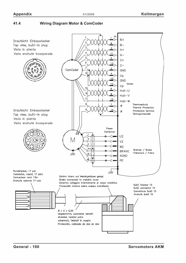
41.4 Wiring Diagram Motor & ComCoder
General - 100 Servomotors AKM
Appendix 01/2009 Kollmorgen
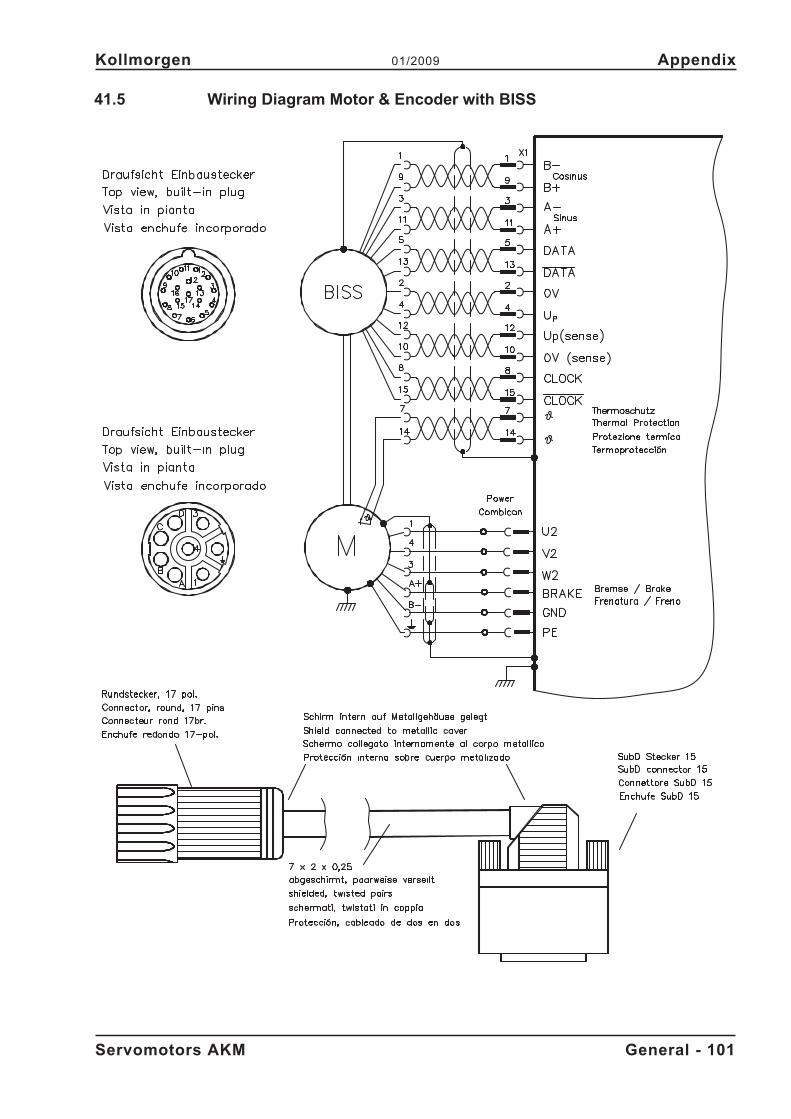
41.5 Wiring Diagram Motor & Encoder with BISS
Servomotors AKM General - 101
Kollmorgen 01/2009 Appendix
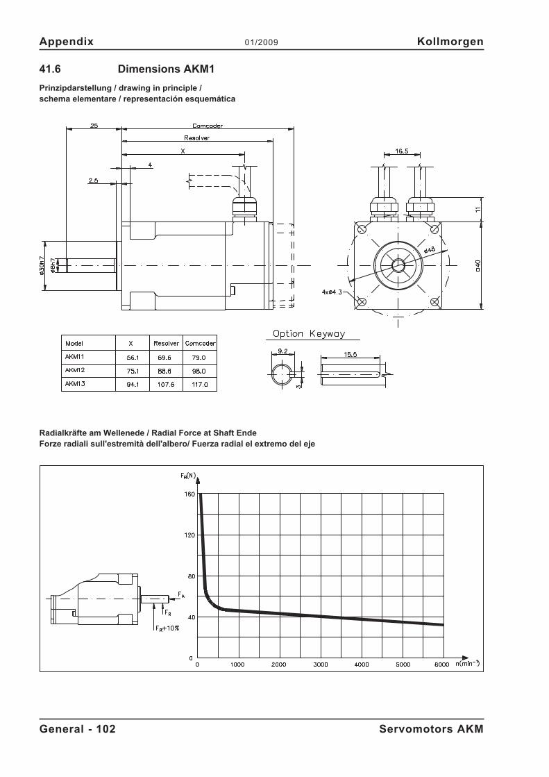
41.6 Dimensions AKM1
Prinzipdarstellung / drawing in principle /schema elementare / representación esquemática
Radialkräfte am Wellenede / Radial Force at Shaft EndeForze radiali sull'estremità dell'albero/ Fuerza radial el extremo del eje
General - 102 Servomotors AKM
Appendix 01/2009 Kollmorgen
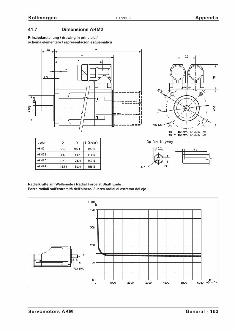
41.7 Dimensions AKM2
Prinzipdarstellung / drawing in principle /schema elementare / representación esquemática
Radialkräfte am Wellenede / Radial Force at Shaft EndeForze radiali sull'estremità dell'albero/ Fuerza radial el extremo del eje
Servomotors AKM General - 103
Kollmorgen 01/2009 Appendix
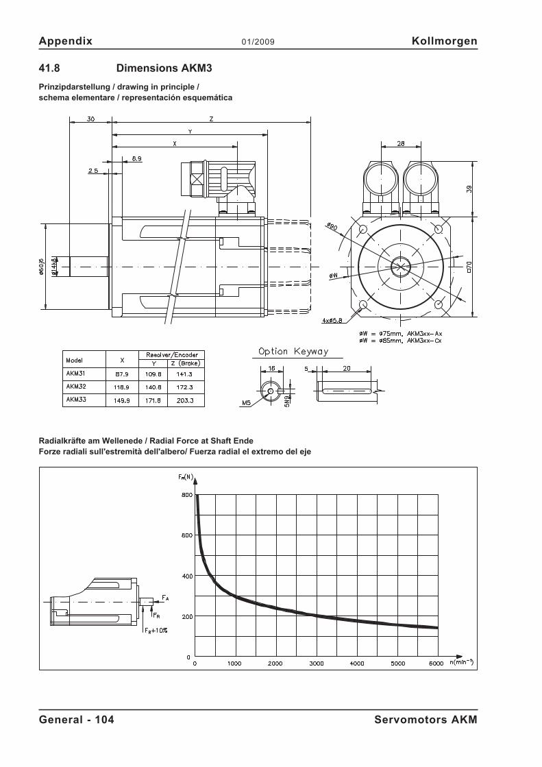
41.8 Dimensions AKM3
Prinzipdarstellung / drawing in principle /schema elementare / representación esquemática
Radialkräfte am Wellenede / Radial Force at Shaft EndeForze radiali sull'estremità dell'albero/ Fuerza radial el extremo del eje
General - 104 Servomotors AKM
Appendix 01/2009 Kollmorgen
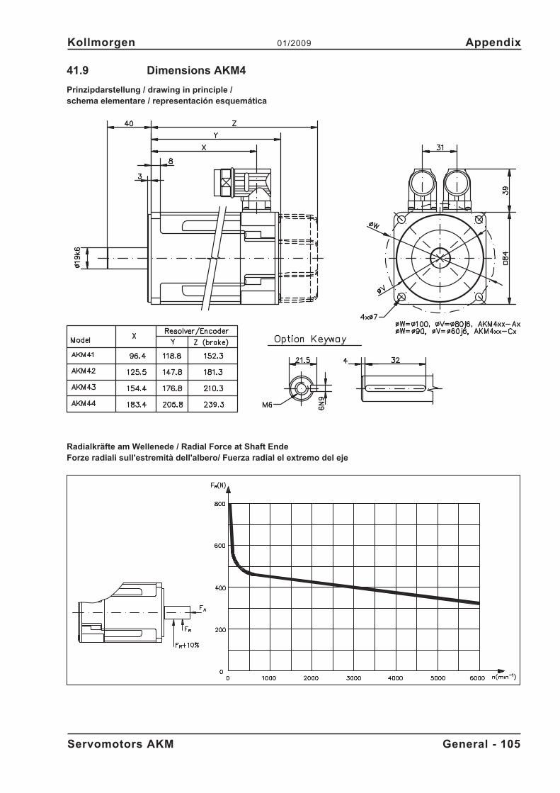
41.9 Dimensions AKM4
Prinzipdarstellung / drawing in principle /schema elementare / representación esquemática
Radialkräfte am Wellenede / Radial Force at Shaft EndeForze radiali sull'estremità dell'albero/ Fuerza radial el extremo del eje
Servomotors AKM General - 105
Kollmorgen 01/2009 Appendix
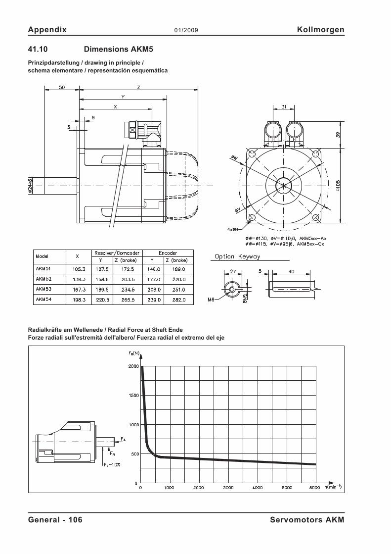
41.10 Dimensions AKM5
Prinzipdarstellung / drawing in principle /schema elementare / representación esquemática
Radialkräfte am Wellenede / Radial Force at Shaft EndeForze radiali sull'estremità dell'albero/ Fuerza radial el extremo del eje
General - 106 Servomotors AKM
Appendix 01/2009 Kollmorgen
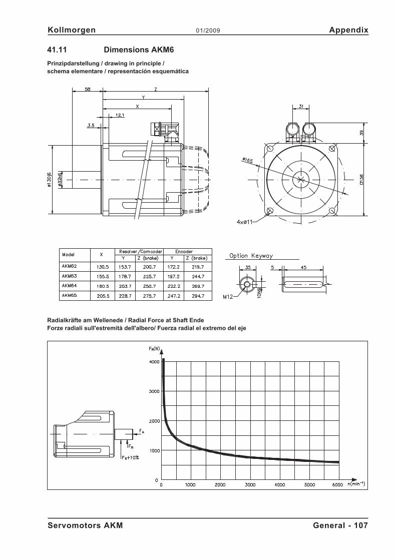
41.11 Dimensions AKM6
Prinzipdarstellung / drawing in principle /schema elementare / representación esquemática
Radialkräfte am Wellenede / Radial Force at Shaft EndeForze radiali sull'estremità dell'albero/ Fuerza radial el extremo del eje
Servomotors AKM General - 107
Kollmorgen 01/2009 Appendix
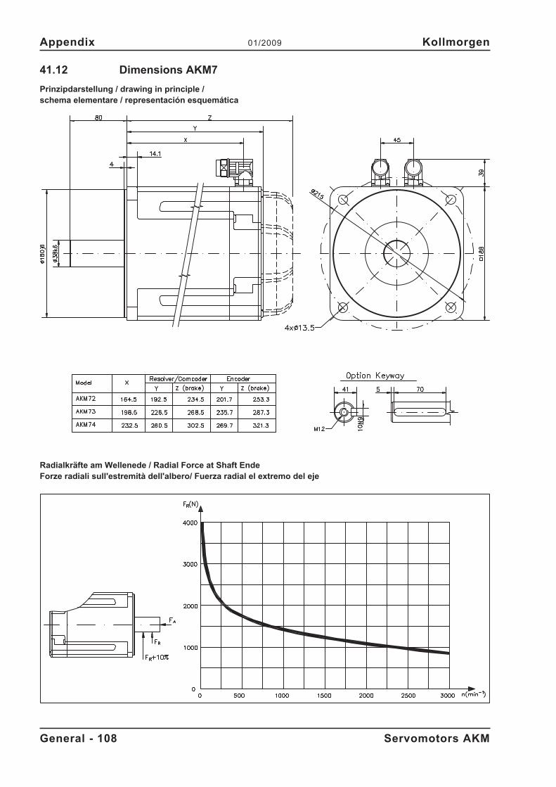
41.12 Dimensions AKM7
Prinzipdarstellung / drawing in principle /schema elementare / representación esquemática
Radialkräfte am Wellenede / Radial Force at Shaft EndeForze radiali sull'estremità dell'albero/ Fuerza radial el extremo del eje
General - 108 Servomotors AKM
Appendix 01/2009 Kollmorgen
This page has been deliberately left blank.
Servomotors AKM General - 109
Kollmorgen 01/2009 Appendix

Vertrieb und Service
Wir bieten Ihnen einen kompetenten und schnellenService. Wählen Sie das zuständige regionaleVertriebszentrum in Deutschland oder kontaktierenSie den europäischen oder nordamerikanischenKundenservice.
Sales and Service
We are committed to quality customer service. Inorder to serve in the most effective way,please contact your local sales representative forassistance. If you are unaware of your local salesrepresentative, please contact us.
Vendite e servizio
Ci impegniamo a fornire un servizio di qualità alcliente. Per servire nel senso più efficace, pregomettasi in contatto con il vostro rappresentante localeper assistenza. Contattateci per maggioriinformazioni.
Venta y servicio
Queremos ofrecer al cliente un servicio de calidad.Para ello les agradecemos que contacten con surepresentante local de ventas. En el caso de que nolo conozcan, no duden en ponerse en contacto connosotros en las siguientes direcciones.
Europe
Danaher Motion Customer Support EuropeE-Mail [email protected] www.DanaherMotion.comTel.: +49(0)203 - 99 79 - 0Fax: +49(0)203 - 99 79 - 216
North America
Danaher Motion Customer Support North AmericaInternet www.DanaherMotion.comE-Mail [email protected]: +1 - 540 - 633 - 3400Fax: +1 - 540 - 639 - 4162

![Accesorios originales para la Clase GL - Auto Bemguiados€¦ · los menús [A], controlar la reproducción de música y el volumen de sonido [B], así como ver el título seleccionado](https://img.pdfslide.org/doc/110x75/607776eef797a72c856a8107/accesorios-originales-para-la-clase-gl-auto-bemguiados-los-mens-a-controlar.jpg)